WO2013111343A1 - 情報処理装置、情報処理システム、通信データ出力方法、及び通信データ出力プログラム - Google Patents
情報処理装置、情報処理システム、通信データ出力方法、及び通信データ出力プログラム Download PDFInfo
- Publication number
- WO2013111343A1 WO2013111343A1 PCT/JP2012/051880 JP2012051880W WO2013111343A1 WO 2013111343 A1 WO2013111343 A1 WO 2013111343A1 JP 2012051880 W JP2012051880 W JP 2012051880W WO 2013111343 A1 WO2013111343 A1 WO 2013111343A1
- Authority
- WO
- WIPO (PCT)
- Prior art keywords
- data
- received
- packet
- observation position
- transmitted
- Prior art date
Links
Images


Classifications
-
- G—PHYSICS
- G06—COMPUTING; CALCULATING OR COUNTING
- G06F—ELECTRIC DIGITAL DATA PROCESSING
- G06F9/00—Arrangements for program control, e.g. control units
- G06F9/06—Arrangements for program control, e.g. control units using stored programs, i.e. using an internal store of processing equipment to receive or retain programs
- G06F9/44—Arrangements for executing specific programs
- G06F9/455—Emulation; Interpretation; Software simulation, e.g. virtualisation or emulation of application or operating system execution engines
-
- H—ELECTRICITY
- H04—ELECTRIC COMMUNICATION TECHNIQUE
- H04L—TRANSMISSION OF DIGITAL INFORMATION, e.g. TELEGRAPHIC COMMUNICATION
- H04L43/00—Arrangements for monitoring or testing data switching networks
- H04L43/04—Processing captured monitoring data, e.g. for logfile generation
-
- H—ELECTRICITY
- H04—ELECTRIC COMMUNICATION TECHNIQUE
- H04L—TRANSMISSION OF DIGITAL INFORMATION, e.g. TELEGRAPHIC COMMUNICATION
- H04L43/00—Arrangements for monitoring or testing data switching networks
- H04L43/12—Network monitoring probes
-
- H—ELECTRICITY
- H04—ELECTRIC COMMUNICATION TECHNIQUE
- H04L—TRANSMISSION OF DIGITAL INFORMATION, e.g. TELEGRAPHIC COMMUNICATION
- H04L47/00—Traffic control in data switching networks
- H04L47/10—Flow control; Congestion control
-
- H—ELECTRICITY
- H04—ELECTRIC COMMUNICATION TECHNIQUE
- H04L—TRANSMISSION OF DIGITAL INFORMATION, e.g. TELEGRAPHIC COMMUNICATION
- H04L49/00—Packet switching elements
- H04L49/20—Support for services
- H04L49/208—Port mirroring
Definitions
- the present invention relates to an information processing apparatus, an information processing system, a communication data output method, and a communication data output program.
- an information processing apparatus such as a server apparatus
- processing for collecting information related to data transmitted / received to / from an external apparatus has been performed.
- a system in which a plurality of server devices are connected to a switch, and all packets passing through a switch having a port mirroring function are mirrored and transmitted to a message analysis device.
- the switch is a device that performs data transfer in the system, and is also referred to as a switching hub.
- the above-described conventional system cannot acquire data transmitted / received in the physical apparatus because data transmitted / received in the physical apparatus is not output from the information processing apparatus.
- an object of the present invention is to output data transmitted and received by a plurality of virtual machines in the same physical device to an external device.
- a data collection unit that collects data transmitted and received within the same physical device by a plurality of virtual machines executed in the physical device, and the data collected by the data collection unit to an external device
- An information processing apparatus comprising: a communication unit that outputs.
- data transmitted and received by a plurality of virtual machines within the same physical device can be output to an external device.
- FIG. 1 is a system configuration example of an information processing system 1 according to a first embodiment of the present invention.
- 2 is a hardware configuration example of a physical server 100. It is a figure which shows the content of the MAC header MH and IP header IH which are the header parts of a packet.
- 3 is a configuration example of a system visualization device 400. It is a figure which shows notionally the outline
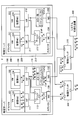
- FIG. 1 is a system configuration example of an information processing system 1 according to a first embodiment of the present invention.
- the information processing system 1 includes physical servers 100 and 200 as examples of information processing apparatuses, physical switches 300 and 310, and a system visualization apparatus 400.
- communication such as Ethernet (registered trademark); Ethernet (registered trademark), IEEE 802.3, FDDI (Fiber-Distributed Data Interface), PPP (Point to Point Protocol), etc. Protocol is adopted.
- FIG. 2 is a hardware configuration example of the physical server 100.
- the physical server 100 includes, for example, a CPU (Central Processing Unit) 100A, a drive device 100B, an auxiliary storage device 100D, a memory device 100E, an interface device 100F, an input device 100G, and a display device 100H. These components are connected via a bus, a serial line, or the like.
- a CPU Central Processing Unit
- the CPU 100A is, for example, a processor having a program counter, an instruction decoder, various arithmetic units, an LSU (Load Store Unit), a general-purpose register, and the like.
- LSU Load Store Unit
- the drive device 100B is a device that can read programs and data from the storage medium 100C.
- the storage medium 100C on which the program is recorded is mounted on the drive device 100B, the program is installed from the storage medium 100C to the auxiliary storage device 100D via the drive device 100B.
- the storage medium 100C is a portable storage medium such as a CD (Compact Disc), a DVD (Digital Versatile Disc), or a USB (Universal Serial Bus) memory.
- the auxiliary storage device 100D is, for example, an HDD (Hard Disk Drive) or a flash memory.
- the program can be installed by the interface device 100F being downloaded from another computer via a network and installed in the auxiliary storage device 100D.
- the network is the Internet, a LAN (Local Area Network), a wireless network, or the like.
- the program may be stored in advance in the auxiliary storage device 100D, a ROM (Read Only Memory), or the like when the physical server 100 is shipped.
- the information processing apparatus shown in FIG. 2 can function as the physical server 100 of this embodiment.
- the memory device 100E is, for example, a RAM (Random Access Memory) or an EEPROM (Electrically Erasable and Programmable Read Only Memory).
- the interface device 100F controls connection with the network.
- the input device 100G is, for example, a keyboard, a mouse, a button, a touch pad, a touch panel, a microphone, or the like.
- the display device 100H is a display device such as an LCD (Liquid Crystal Display) or a CRT (Cathode Ray Tube).
- the physical server 100 may include other types of output devices such as a printer and a speaker in addition to the display device 100H.
- the physical server 100 is controlled by a host OS (Operating System) 110 and a guest OS 120 operating on the host OS 110. Further, the physical server 100 includes a NIC (Network Interface Card) 130 connected to the physical switch 300 and a NIC 132 connected to the physical switch 310.
- a host OS Operating System
- a guest OS operating on the host OS 110.
- the physical server 100 includes a NIC (Network Interface Card) 130 connected to the physical switch 300 and a NIC 132 connected to the physical switch 310.
- NIC Network Interface Card
- the physical server 100 includes software means such as VIF (Virtual Interface) 111 and 112, a bridge 113, and a mirror unit 114 that are constructed on the host OS 110.
- VIF Virtual Interface
- the physical server 100 includes software means such as VIF (Virtual Interface) 111 and 112, a bridge 113, and a mirror unit 114 that are constructed on the host OS 110.
- the physical server 100 also has software means such as VMs (Virtual Machines) 121 and 122 constructed on the guest OS 120.
- the VMs 121 and 122 have virtual NICs 123 and 124, respectively.
- the physical server 200 is controlled by the host OS 210 and the guest OS 220 operating on the host OS 210.
- the physical server 200 also includes a NIC 230 connected to the physical switch 300 and a NIC 232 connected to the physical switch 310.
- the physical server 200 includes software means such as VIFs 211 and 212, a bridge 213, and a mirror unit 214 that are constructed on the host OS 210.
- the physical server 200 includes software means such as VMs 221 and 222 that are built on the guest OS 220.
- the VMs 221 and 222 have virtual NICs 223 and 224, respectively.
- Each of the VMs 121, 122, 221, and 222 functions as, for example, a Web server, an application server, a database server, and the like, and can provide various information services to client computers connected to the information processing system 1.
- two VMs exist on each physical server.
- the number of VMs present on each physical server may be any number.
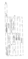
- FIG. 3 is a diagram showing the contents of a MAC (Media Access Control) header MH and an IP header IH, which are packet header portions.
- MAC Media Access Control
- the packet “A” is transferred to the physical switch 300 by the virtual NIC 123, VIF 111, bridge 113, and NIC 130.
- the packet “A” is transferred to the VM 222 by the physical switch 300, the NIC 230, the bridge 213, the VIF 211, and the virtual NIC 223.
- the destination of the packet is determined by referring to the destination MAC address corresponding to each VIF in the bridges 113 and 213, the physical switch 300, and the like.
- communication between VMs on the same physical server is performed via the bridge 113 in packet units.
- the packet “B” is transmitted from the VM 121 to the VM 122, the packet “B” is transferred by the virtual NIC 123, VIF 111, bridge 113, VIF 112, and virtual NIC 124.
- the physical switch 300 has a MAC address / port correspondence table (MAC address table) (not shown) and performs packet transfer as described above. Further, the physical switch 300 has a port mirroring function, and performs processing (mirroring) for transmitting a copy of the transferred packet to the physical switch 310.
- MAC address table MAC address table
- the mirror unit 114 collects packets transmitted / received between VMs on the same physical server, and transmits the collected packets to the NIC 132.
- the NIC 132 transfers the packet input from the mirror unit 114 to the physical switch 310.
- the function of the mirror unit 214 is the same as that of the mirror unit 114.
- the mirror units 114 and 214 use packet buffers 114A and 214A, respectively.
- the physical switch 310 transmits the packet input from the physical switch 300 and the NICs 132 and 232 to the system visualization apparatus 400. Through these processes, packets transmitted / received between the physical servers and within the physical server are input to the system visualization device 400, and data of all packets transmitted / received within the information processing system 1 are collected in the system visualization device 400. .
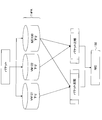
- FIG. 4 is a configuration example of the system visualization device 400.
- the system visualization device 400 includes a capture unit 410, a capture data storage unit 420, a message analysis unit 430, a protocol log storage unit 440, a log analysis unit 450, and a transaction data storage unit 460.
- the capture unit 410 receives the packet from the physical switch 310 and stores it in the capture data storage unit 420.
- the message analysis unit 430 extracts predetermined data from the packet stored in the capture data storage unit 420 and stores it in the protocol log storage unit 440.
- the log analysis unit 450 performs log analysis processing using the data stored in the protocol log storage unit 440 and stores it in the transaction data storage unit 460.
- the configuration of the system visualization device 400 is merely an example, and other modes may be adopted.
- FIG. 5 is a diagram conceptually showing an outline of processing by the mirror unit 114.
- the mirror unit 114 captures packets transmitted and received by all VMs of the physical server 100 (that is, packets passing through the VIFs 111 and 112), and packet buffers for each VM and each uplink / downlink. Store in the corresponding area of 114A.
- the mirror unit 114 distinguishes from an upstream packet transmitted to the VM 121, a downstream packet transmitted from the VM 121 to another VM, an upstream packet transmitted to the VM 122, and a downstream packet transmitted from the VM 122 to another VM.
- upstream packet transmitted to the VM 121 is abbreviated as “upstream packet of the VM 121”
- downstream packet transmitted from the VM 121 to another VM is abbreviated as “downstream packet of the VM 121”.
- upstream packet transmitted to the VM 122 is abbreviated as “upstream packet of VM 122”
- downstream packet transmitted from the VM 122 to another VM is abbreviated as “downstream packet of VM 122”.
- an upward arrow indicates an upstream packet
- a downward arrow indicates a downstream packet
- the upstream packet is transferred in a direction closer to the VM associated with the VIF (the VIF is in charge of packet transmission / reception) in the VIF where the packet is captured. It can be defined as a packet.
- the downstream packet can be defined as a packet that is transferred in a direction away from the VM associated with the VIF in the VIF where the packet is captured.
- VMs associated with the position where the packet was captured an example is when captured by the NIC 130 in the second embodiment.
- the “associated VM” may be read as “any one of the associated VMs”.
- VMs associated with the NIC 130 are all VMs (121, 122) on the physical server 100
- VMs associated with the NIC 230 are all VMs (221, 222) on the physical server 200.
- FIG. 6 is a flowchart showing a flow of processing for determining whether the mirror unit 114 is an upstream packet or a downstream packet. This flowchart is executed every time a packet is captured.
- the mirror unit 114 compares the destination MAC address in the MAC header of the captured packet with the MAC address of the VM corresponding to the VIF at which the packet is captured (S500). Then, the mirror unit 114 determines whether the destination MAC address matches the MAC address of the VM (S502).
- the mirror unit 114 determines that the packet is an uplink packet and stores the packet in the corresponding area of the packet buffer 114A (S504).
- the mirror unit 114 compares the source MAC address in the packet MAC header with the VM MAC address corresponding to the VIF at which the packet was captured (S506). Then, the mirror unit 114 determines whether or not the transmission source MAC address matches the VM MAC address (S508).
- the mirror unit 114 determines that the packet is a downlink packet, and stores the packet in the corresponding area of the packet buffer 114A (S510).
- the mirror unit 114 regards it as error data and deletes the packet (S512).
- the captured time is given to the packet stored in S504 or S510.
- the process of determining whether the mirror unit 114 is an upstream packet or a downstream packet may be performed using a transmission destination address or a transmission source address included in the IP header.
- the mirror unit 114 holds the IP address of each VM as table data in association with the VIF.
- FIG. 7 is another example of a flowchart showing a flow of processing for determining whether the mirror unit 114 is an upstream packet or a downstream packet. This flowchart is executed every time a packet is captured.
- the mirror unit 114 compares the destination address in the IP header of the captured packet with the IP address of the VM corresponding to the VIF that is the position where the packet was captured (S600). Then, the mirror unit 114 determines whether or not the transmission destination address matches the IP address of the VM (S602).
- the mirror unit 114 determines that the packet is an uplink packet and stores the packet in the corresponding area of the packet buffer 114A (S604).
- the mirror unit 114 compares the source address in the IP header of the captured packet with the IP address of the VM corresponding to the VIF at which the packet was captured ( S606). Then, the mirror unit 114 determines whether or not the transmission source address matches the IP address of the VM (S608).
- the mirror unit 114 determines that the packet is a downstream packet, and stores the packet in the corresponding area of the packet buffer 114A (S610).
- the mirror unit 114 regards it as error data and deletes the packet (S612).
- the captured time is given to the packet stored in S604 or S610.
- the mirror unit 114 compares the packets on the same physical server 100 as shown in the lower part of FIG.
- the packet transmitted / received between the VMs is extracted.
- the packet comparison is performed for each of the combination of the uplink packet of the VM 121 and the downlink packet of the VM 122, and the combination of the downlink packet of the VM 121 and the uplink packet of the VM 122.
- the mirror unit 114 compares the uplink packet of a certain VM with the downlink packets of all other VMs, and the downlink packet of the VM and all the other VMs. Comparison of uplink packets of VMs is performed for all VMs.
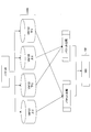
- FIG. 8 is a diagram illustrating a combination of packet comparisons performed when the number of VMs is three.
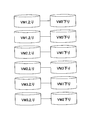
- FIG. 9 is a diagram illustrating a combination of packet comparisons performed when the number of VMs is four. 8 and 9, each VM is represented as VM1, VM2,.
- the mirror unit 114 performs ( n P 2 ) packet comparisons, where n is the number of VMs.
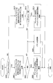
- FIG. 10 is a flowchart showing a processing flow when the mirror unit 114 performs packet comparison. This flow is repeatedly executed, for example, every predetermined time.
- the mirror unit 114 sequentially extracts one packet from the area where the “upstream packet of the VM 121” is stored in the packet buffer 114A (S700), and further extracts one packet from the area where the “downstream packet of the VM 122” is stored. (S702).
- the packet extraction order is determined according to, for example, FIFO (First In, First Out).
- the mirror unit 114 compares “ID”, “source address”, and “destination address”, which are information for identifying IP packets in the IP header in the packets extracted in S700 and S702 (S704). Then, the mirror unit 114 determines whether or not “ID”, “transmission source address”, and “transmission destination address” of the IP header all match (S706).
- the mirror unit 114 transmits one of the matched packet pairs (for example, a downstream packet) to the NIC 132. (S708). Then, the mirror unit 114 deletes the matched packet pair from the packet buffer 114A (S710). After the process of S710, the mirror unit 114 proceeds to S714, which will be described later, and executes the process.
- the mirror unit 114 determines whether or not all packets in the area storing “downstream packet of VM122” have been extracted in the loop processing related to “downstream packet of VM122”. Determination is made (S712).
- the loop processing regarding “downlink packet of VM 122” is loop processing in which the processing of S702 to S710 is repeated. In the loop processing, when all the packets of “downstream packet of VM 122” have not been extracted, the mirror unit 114 returns to S702, extracts the next packet from “downstream packet of VM 122”, and executes the processing after S704. .
- the mirror unit 114 determines whether or not all packets of “upstream packets of VM 121” have been extracted in the loop processing related to “upstream packets of VM 121” Is determined (S714).
- the loop process related to “upstream packet of VM 121” is a loop process in which the processes of S700 to S712 are repeated. In the loop processing, when all the packets of the “upstream packet of VM 121” have not been extracted, the mirror unit 114 returns to S700, extracts the next packet from the “upstream packet of VM 121”, and executes the processing after S702. .
- the mirror unit 114 sequentially extracts one packet from the area storing the “down packet of the VM 121” in the packet buffer 114A (S720). Further, the mirror unit 114 sequentially extracts one packet from the area storing the “upstream packet of the VM 122” (S722).
- the mirror unit 114 compares the “ID”, “source address”, and “destination address” of the IP header in the packets extracted in S720 and S722 (S724). Then, the mirror unit 114 determines whether or not “ID”, “transmission source address”, and “transmission destination address” of the IP header all match (S726).
- the mirror unit 114 selects one of the matched packet pairs (for example, a downstream packet) from the NIC 132. (S728). Then, the mirror unit 114 deletes the matched packet pair from the packet buffer 114A (S730).
- the mirror unit 114 determines whether or not all packets in the area storing “upstream packet of VM 122” have been extracted in the loop processing related to “upstream packet of VM 122”. Determination is made (S732).
- the loop process related to “upstream packet of VM 122” is a loop process in which the processes of S722 to S730 are repeated. In the loop process, when all the packets of the “upstream packet of VM 122” have not been extracted, the mirror unit 114 returns to S722, extracts the next packet, and executes the processes after S724.
- the mirror unit 114 determines whether or not all the packets of the “downstream packet of the VM 121” have been extracted in the loop processing related to the “downstream packet of the VM 121” (S734). ).
- the loop process related to “downstream packet of VM 121” is a loop process in which the processes of S720 to S732 are repeated. In the loop process, when all the packets of “downstream packet of VM 121” have not been extracted, the mirror unit 114 returns to S720, extracts the next packet, and executes the processes after S722.
- the mirror unit 114 deletes all packets stored in the packet buffer 114A that have been captured for a fixed time (S740).
- FIG. 10 the flowchart shown in FIG. 10 is for the case where the number of VMs existing on the physical server 100 is two. If the number n of VM present on the physical server 100 is three or more, a loop process such as S700 ⁇ S714, S720 ⁇ S734, may be performed as (n P 2).
- FIG. 11 is a diagram illustrating an information processing system 1 # and physical servers 100 # and 200 # according to a modification.
- “#” is added to the reference numerals of the corresponding components of the information processing system 1 and the physical servers 100 and 200 of the first embodiment.
- the mirror unit 114 # included in the physical server 100 # of the modified example collects all the packets passing through the VIFs 111 # and 112 # and transmits them to the NIC 132 #.
- data transmitted and received by a plurality of virtual machines within the same physical server can be output to an external device.
- the external device that is, the system visualization device, can collect both data transmitted and received by a plurality of virtual machines in the same physical server and data transmitted and received by the physical server to and from the external device.
- the information processing system and the physical server of the first embodiment shown in FIG. 1 can reduce the packet transfer load of the NIC 132 as compared with the information processing system and the physical server of the modified example. This is because the NIC 132 # transfers “A ⁇ B ⁇ D ⁇ C ⁇ ” in the physical server 100 # of the modified example, whereas the NIC 132 transfers “B ⁇ D ⁇ ” in the physical server 100 of the present embodiment. .
- the information processing system and the physical server of the first embodiment collect packets transmitted / received between VMs on the same physical server and transmit them to the NIC 132.
- Mirroring of packets transmitted / received between different physical servers is performed by the physical switch 300. I leave it to the function. For this reason, the packet transfer load in the NIC 132 is not excessive, and smooth information transmission / reception is realized. Further, it is not necessary to mount the NIC 132 having an excessively high function, and an increase in cost and weight can be suppressed. The same applies to the relationship between the mirror unit 214 and the NIC 232.
- FIG. 12 is a system configuration example of the information processing system 2 according to the second embodiment of the present invention.
- the information processing system 2 according to the second embodiment differs from the first embodiment in the processing content of the mirror unit. For this reason, not only the mirror units 114 * and 214 * but also the packet buffers used by the mirror units 114 * and 214 * A are denoted by the same reference numerals as those in the first embodiment. To explain.
- FIG. 13 is a diagram conceptually showing an outline of processing by the mirror unit 114 *.
- the mirror unit 114 * captures downlink packets transmitted / received by all VMs of the physical server 100 and downlink packets passing through the NIC 130, and stores them in the corresponding areas of the packet buffer 114 * A. To do. Specifically, the mirror unit 114 * distinguishes the downlink packet transmitted from the VM 121 to another VM, the downlink packet transmitted from the VM 122 to the other VM, and the downlink packet transferred from the NIC 130 to the physical switch 300. * Store in A.
- downlink packets transmitted from the VM 121 to other VMs are abbreviated as “downlink packets of the VM 121”, and downlink packets transmitted from the VM 122 to other VMs are abbreviated as “downlink packets of the VM 122”.
- downlink packets transmitted from the NIC 130 to the physical switch 300 are abbreviated as “downlink packet of NIC 130”.
- the “upstream packet” captured by the NIC 130 is a packet that the NIC 130 receives from the external device (physical switch 300), and the “downstream packet” is transmitted by the NIC 130 to the external device (physical switch 300). Packet.
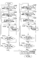
- FIG. 14 is a flowchart showing a processing flow in which the mirror unit 114 * selectively collects downstream packets. This flowchart is executed each time a packet is captured by the mirror unit 114 *.
- the mirror unit 114 * determines whether the packet is captured by the VIF 111 or the VIF 112 (S800).
- the mirror unit 114 * When the packet is captured by the VIF 111 or the VIF 112, the mirror unit 114 * performs the following processing.
- the mirror unit 114 * compares the source MAC address in the MAC header of the captured packet with the MAC address of the VM corresponding to the VIF at which the packet was captured (S802). Then, the mirror unit 114 * determines whether or not the source MAC address matches the VM MAC address (S804).
- the mirror unit 114 * determines that the packet is a downstream packet, and stores the packet in the corresponding area of the packet buffer 114 * A (S806).
- the mirror unit 114 * If the source MAC address and the VM MAC address do not match, the mirror unit 114 * considers it as an uplink packet or error data and deletes the packet (S808).
- the mirror unit 114 * performs the following processing.
- the mirror unit 114 * compares the source MAC address with the MAC addresses of all VMs (121, 122) of the physical server 100 (S810). Then, the mirror unit 114 * determines whether or not the source MAC address matches the MAC address of any VM (S812).
- the mirror unit 114 * determines that the packet is a downlink packet and stores the packet in the corresponding area of the packet buffer 114 * A (S814).
- the mirror unit 114 * If the source MAC address does not match the MAC addresses of all VMs, the mirror unit 114 * considers it as an upstream packet or error data and deletes the packet (S808).
- the captured time is given to the packet stored in S806 or S814.
- FIG. 15 is another example of a flowchart showing a processing flow in which the mirror unit 114 * selectively collects downstream packets. This flowchart is executed each time a packet is captured by the mirror unit 114 *.
- the mirror unit 114 * determines whether the packet is captured by the VIF 111 or the VIF 112 (S900).
- the mirror unit 114 * When the packet is captured by the VIF 111 or the VIF 112, the mirror unit 114 * performs the following processing. The mirror unit 114 * compares the transmission source address in the IP header of the captured packet with the IP address of the VM corresponding to the VIF that is the position where the packet was captured (S902). Then, the mirror unit 114 * determines whether or not the transmission source address matches the IP address of the VM (S904).
- the mirror unit 114 * determines that the packet is a downstream packet, and stores the packet in the corresponding area of the packet buffer 114 * A (S906).
- the mirror unit 114 * deletes the packet as an upstream packet or error data (S908).
- the mirror unit 114 * performs the following processing.
- the mirror unit 114 * compares the source address in the IP header of the captured packet with the IP addresses of all VMs (121, 122) that the physical server 100 has (S910). Then, the mirror unit 114 * determines whether or not the transmission source address matches the IP address of any VM (S912).
- the mirror unit 114 * determines that the packet is a downstream packet, and stores the packet in the corresponding area of the packet buffer 114 * A (S914).
- the mirror unit 114 * If the source address does not match all VM IP addresses, the mirror unit 114 * considers the packet to be an uplink packet or error data and deletes the packet (S908).
- the captured time is given to the packet stored in S906 or S914.
- the packet is compared between the VMs on the same physical server 100 as shown in the lower part of FIG. Extracted packets. The packet comparison is performed for each of the combination of the downlink packet of the VM 121 and the downlink packet passing through the NIC 130 and the combination of the downlink packet of the VM 122 and the downlink packet passing through the NIC 130.
- FIG. 16 is a flowchart showing a flow of processing when the mirror unit 114 * performs packet comparison. This flow is repeatedly executed, for example, every predetermined time.
- the mirror unit 114 * sequentially extracts one packet from the area storing the “downstream packet of the VM 121” in the packet buffer 114 * A (S1000), and sequentially collects the packets from the area storing the “downstream packet of the NIC 130”. (S1002).
- the packet extraction order is determined according to, for example, FIFO (First In, First Out).
- the mirror unit 114 * compares the “ID”, “source address”, and “destination address” of the IP header in the packets extracted in S1000 and S1002 (S1004). Then, the mirror unit 114 * determines whether or not the “ID”, “transmission source address”, and “transmission destination address” of the IP header all match (S1006).
- the mirror unit 114 * deletes the packet pair from the packet buffer 114 * A (S1008). After the process of S1008, the mirror unit 114 * proceeds to S1012 described later and executes the process.
- the loop processing relating to “the downstream packet of NIC 130” is a loop processing in which the processing of S1002 to S1008 is repeated. In the loop processing, when all the packets of “downstream packet of NIC 130” have not been extracted, the mirror unit 114 * returns to S1002, extracts the next packet from “downstream packet of NIC 130”, and executes the processing after S1004 To do.
- the mirror unit 114 * When all the packets of “the downstream packet of NIC 130” are taken out or after S1008, the mirror unit 114 * performs the following processing.
- the mirror unit 114 * determines whether or not all the packets of the “downstream packet of the VM 121” have been extracted in the loop processing related to the “downstream packet of the VM 121” (S1012).
- the loop processing related to “downstream packet of VM 121” is loop processing in which the processing of S1000 to S1010 is repeated. In the loop processing, when all the packets of “downstream packet of VM 121” are not extracted, the mirror unit 114 * returns to S1000, extracts the next packet from “downstream packet of VM 121”, and executes the processing from S1002 onward. To do.
- the mirror unit 114 * sequentially extracts one packet from the area storing the “downstream packet of the VM 122” in the packet buffer 114 * A (S1020). Next, the mirror unit 114 * sequentially takes out one packet from the area storing “the downstream packet of the NIC 130” (S1022).
- the mirror unit 114 * compares the “ID”, “source address”, and “destination address” of the IP header in the packets extracted in S1020 and S1022 (S1024). Then, the mirror unit 114 * determines whether or not the “ID”, “transmission source address”, and “transmission destination address” of the IP header all match (S1026).
- the mirror unit 114 * deletes the packet pair from the packet buffer 114 * A (S1028). After the process of S1028, the mirror unit 114 * proceeds to S1012 described later and executes the process.
- the loop processing related to “downlink packet of NIC 130” is loop processing in which the processing of S1022 to S1028 is repeated.
- the mirror unit 114 * returns to S1022, extracts the next packet from “downstream packet of NIC 130”, and executes the processing after S1024. To do.
- the mirror unit 114 * When all the packets of the “downstream packet of NIC 130” are taken out or after S1028, the mirror unit 114 * performs the following processing.
- the mirror unit 114 * determines whether or not all the packets of the “downstream packet of the VM 122” have been extracted in the loop processing related to the “downstream packet of the VM 122” (S1032).
- the loop process related to “downlink packet of VM 122” is a loop process in which the processes of S1020 to S1030 are repeated.
- the mirror unit 114 * returns to S1020, extracts the next packet from “downstream packet of VM 122”, and executes the processing from S1022.
- the mirror unit 114 * transmits, to all the packets stored in the packet buffer 114 * A, a packet that has passed for a certain period of time to the NIC 132. (S1040).
- the mirror unit 114 * includes a loop process such as S1000 ⁇ S1012, S1020 ⁇ S1032, it may be performed as (n P 2).
- the difference between the present embodiment and the information processing system 1 # and the physical servers 100 # and 200 # of the modification shown in FIG. 11 is the same as that of the first embodiment, and thus the description thereof is omitted.
- the number of capture positions increases, but the number of areas for storing captured packets can be reduced in the packet buffer 114 * A (see FIGS. 5 and 13).
- FIG. 17 is a system configuration example of the information processing system 3 according to the third embodiment of the present invention.
- the host OSs 110 and 120 of the physical servers 100 and 200 include MAC address tables 115 and 125, respectively.
- the MAC address table 115 is table data set on the auxiliary storage device 100D or the memory device 100E.
- the MAC address table 215 is table data set on the auxiliary storage device 200D or the memory device 200E.
- the information processing system 3 according to the third embodiment of the present invention is different from the first embodiment in the processing contents of the bridge and the mirror unit.
- the bridges 113 ** and 213 ** and the mirror portions 114 ** and 214 ** are indicated, and the other components are denoted by the same reference numerals as those in the first embodiment.
- FIG. 18 is a flowchart showing a flow of processing executed by the bridge 113 ** and the mirror unit 114 ** or the bridge 213 ** and the mirror unit 214 ** according to the third embodiment.
- the processing is performed by the bridge 113 ** and the mirror unit 114 **, but the same processing is performed by the bridge 213 ** and the mirror unit 214 **.
- the bridge 113 ** waits until a packet is received from the VIF 111 or 112 or the NIC 130 (S1100). When the packet is received, the bridge 113 ** notifies the mirror unit 114 ** to that effect (S1102).
- the mirror unit 114 ** determines whether the received port is a port corresponding to the VIF 111 or 112 among the virtual ports of the bridge 113 ** (S1104).
- the mirror unit 114 ** If the received virtual port of the bridge 113 ** is not a port corresponding to the VIF 111 or 112, the mirror unit 114 ** returns to S1100 and waits until the bridge 113 ** receives a packet.
- the mirror unit 114 ** searches the MAC address table 115 using the packet destination MAC address. (S1106).
- FIG. 19 is an example of data stored as the MAC address table 115.
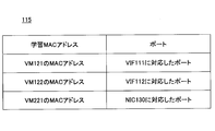
- the MAC address table 115 stores the MAC address learned by the bridge 113 ** (learned MAC header address) in association with the virtual port.
- the mirror unit 114 ** determines whether or not the transmission destination MAC address of the packet is registered in the MAC address table 115 (S1108).
- the mirror unit 114 ** copies the packet from the bridge 113 ** and transmits the copied packet to the NIC 132 (S1110).
- the bridge 113 ** has a function of registering the source MAC address of the received packet in the MAC address table 115 in association with the virtual port that has received the packet.
- the mirror unit 114 ** determines whether or not the port corresponding to the destination MAC address in the MAC address table 115 is a port corresponding to the VIF 111 or 112 (S1112). .
- the mirror unit 114 ** returns to S1100 and waits until the bridge 113 ** receives a packet.
- the mirror unit 114 ** copies the packet from the bridge 113 ** and transmits the copied packet to the NIC 132 (S1110).
- the packet B shown in FIG. 17 is transmitted from the VM 121 to the VM 122 as a result of the processing, if the MAC address of the VM 122 that is the transmission destination MAC address of the packet B is registered in the MAC address table 115, the packet B is transmitted to the NIC 132. Is sent. Similarly, when the MAC address of the VM 122 is not registered in the MAC address table 115, the packet B is transmitted to the NIC 132 in the same manner. In the latter case, since the MAC address of the VM 122 is registered in the MAC address table 115, a packet is transmitted to the NIC 132 by obtaining a positive determination in S1112 in the subsequent processing.
- the packet A shown in FIG. 17 is transmitted from the VM 121 to the VM 221.
- the port corresponds to the NIC 130, and the packet A is not transmitted to the NIC 132.
- the packet A is transmitted to the NIC 132.
- the packet A is transmitted to the system visualization device 400 in duplicate, and thereafter, since it is registered in the MAC address table 115, the duplication is It is within an acceptable range.
- the packet C is transmitted from the VM 221 to the VM 121, the packet C is received by the port corresponding to the NIC 130 in the bridge 113 **, and therefore the packet C is not transmitted to the NIC 132.
- the difference between the present embodiment and the information processing system 1 # and the physical servers 100 # and 200 # of the modification shown in FIG. 11 is the same as that of the first embodiment, and thus the description thereof is omitted.
- the information processing apparatus of the third embodiment may collect packets using IP addresses instead of MAC addresses, as in the first embodiment.
- the mirror unit 114 * in the second embodiment captures downstream packets transmitted and received by all VMs and downstream packets passing through the NIC 130, and excludes those whose contents match. Absent.
- the mirror unit 114 * in the second embodiment may capture upstream packets transmitted / received by all VMs and upstream packets that pass through the NIC 130, and may transmit packets to the NIC 132 by excluding those that match. .
- the physical switches 300 and 310 may be integrated into a physical switch.
- the arrangement of the OS and VM in each embodiment is an arbitrary matter, and the present invention can be applied if a plurality of VMs exist on the information processing apparatus (physical server).
- each physical server separates the NIC that performs transmission / reception with the external device and the NIC that transmits the packet collected by the mirror unit, but the transmission / reception packet with the external device and the packet collected by the mirror unit using the same NIC Both of them may be handled.
- the present invention can be used in the computer manufacturing industry, the computer software industry, the information service providing industry, and the like.
Landscapes
- Engineering & Computer Science (AREA)
- Computer Networks & Wireless Communication (AREA)
- Signal Processing (AREA)
- Software Systems (AREA)
- Theoretical Computer Science (AREA)
- Data Mining & Analysis (AREA)
- Physics & Mathematics (AREA)
- General Engineering & Computer Science (AREA)
- General Physics & Mathematics (AREA)
- Data Exchanges In Wide-Area Networks (AREA)
Abstract
物理装置内で実行される複数の仮想マシンが、同一の物理装置内で送受信するデータを収集するデータ収集部と、前記データ収集部により収集されたデータを外部装置に出力する通信部と、を備える情報処理装置。
Description
本発明は、情報処理装置、情報処理システム、通信データ出力方法、及び通信データ出力プログラムに関する。
従来、サーバ装置等の情報処理装置において、外部装置との間で送受信されるデータに関する情報を収集する処理が行われている。
例えば、複数のサーバ装置がスイッチに接続されたシステムであって、ポートミラーリング機能を有するスイッチを通過する全てのパケットをミラーリングしてメッセージ分析装置に送信するシステムが開示されている。スイッチは、システムにおけるデータ転送を行う装置であり、スイッチングハブとも称される。
しかしながら、上記従来のシステムは、物理的な装置内で送受信されるデータが情報処理装置から出力されないため、物理的な装置内で送受信されるデータを取得することができない。
一つの側面では、本発明は、複数の仮想マシンが同一の物理装置内で送受信するデータを、外部装置に出力することを目的とする。
本発明の一態様は、物理装置内で実行される複数の仮想マシンが、同一の物理装置内で送受信するデータを収集するデータ収集部と、前記データ収集部により収集されたデータを外部装置に出力する通信部と、を備える情報処理装置である。
一実施態様によれば、複数の仮想マシンが同一の物理装置内で送受信するデータを、外部装置に出力することができる。
以下、本発明を実施するための形態について、添付図面を参照しながら実施例を挙げて説明する。
<第1実施例>
以下、図面を参照し、本発明の第1実施例に係る情報処理装置、通信データ出力方法、通信データ出力プログラム、並びにこれらを利用した情報処理システムについて説明する。
以下、図面を参照し、本発明の第1実施例に係る情報処理装置、通信データ出力方法、通信データ出力プログラム、並びにこれらを利用した情報処理システムについて説明する。
図1は、本発明の第1実施例に係る情報処理システム1のシステム構成例である。情報処理システム1は、情報処理装置の一例としての物理サーバ100、200と、物理スイッチ300、310と、システム可視化装置400と、を備える。各物理サーバ、各物理スイッチ等が形成するネットワークでは、例えばイーサネット(登録商標);Ethernet(登録商標)、IEEE802.3、FDDI(Fiber-Distributed Data Interface)、PPP(Point to Point Protocol)等の通信プロトコルが採用される。
図2は、物理サーバ100のハードウエア構成例である。物理サーバ100は、例えば、CPU(Central Processing Unit)100Aと、ドライブ装置100Bと、補助記憶装置100Dと、メモリ装置100Eと、インターフェース装置100Fと、入力装置100Gと、ディスプレイ装置100Hと、を備える。これらの構成要素は、バスやシリアル回線等を介して接続されている。
CPU100Aは、例えば、プログラムカウンタや命令デコーダ、各種演算器、LSU(Load Store Unit)、汎用レジスタ等を有するプロセッサである。
ドライブ装置100Bは、記憶媒体100Cからプログラムやデータを読み込み可能な装置である。プログラムを記録した記憶媒体100Cがドライブ装置100Bに装着されると、プログラムが記憶媒体100Cからドライブ装置100Bを介して補助記憶装置100Dにインストールされる。記憶媒体100Cは、例えば、CD(Compact Disc)、DVD(Digital Versatile Disc)、USB(Universal Serial Bus)メモリ等の可搬型の記憶媒体である。また、補助記憶装置100Dは、例えば、HDD(Hard Disk Drive)やフラッシュメモリである。
プログラムのインストールは、上記のように記憶媒体100Cを用いる他、インターフェース装置100Fがネットワークを介して他のコンピュータよりダウンロードし、補助記憶装置100Dにインストールすることによって行うこともできる。ネットワークは、インターネット、LAN(Local Area Network)、無線ネットワーク等である。また、プログラムは、物理サーバ100の出荷時に、予め補助記憶装置100DやROM(Read Only Memory)等に格納されていてもよい。
このようにしてインストール又は予め格納されたプログラムをCPU100Aが実行することにより、図2に示す態様の情報処理装置が、本実施例の物理サーバ100として機能することができる。
メモリ装置100Eは、例えば、RAM(Random Access Memory)やEEPROM(Electrically Erasable and Programmable Read Only Memory)である。インターフェース装置100Fは、上記ネットワークとの接続等を制御する。
入力装置100Gは、例えば、キーボード、マウス、ボタン、タッチパッド、タッチパネル、マイク等である。また、ディスプレイ装置100Hは、例えば、LCD(Liquid Crystal Display)やCRT(Cathode Ray Tube)等の表示装置である。物理サーバ100は、ディスプレイ装置100Hの他、プリンタ、スピーカ等の他の種類の出力装置を備えてもよい。
なお、物理サーバ200については、物理サーバ100と同じハードウエア構成を採用することができるため、説明を省略する。
図1に戻り、情報処理システム1の各構成要素について説明する。
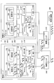
物理サーバ100は、ホストOS(Operating System)110と、ホストOS110上で動作するゲストOS120とによって制御される。また、物理サーバ100は、物理スイッチ300に接続されたNIC(Network Interface Card)130と、物理スイッチ310に接続されたNIC132と、を備える。
また、物理サーバ100は、ホストOS110上に構築される、VIF(Virtual Interface)111、112、ブリッジ113、ミラー部114等のソフトウエア手段を有する。
また、物理サーバ100は、ゲストOS120上に構築される、VM(Virtual Machine;仮想マシン又は仮想計算機)121、122等のソフトウエア手段を有する。VM121、122は、それぞれ仮想NIC123、124を有している。
同様に、物理サーバ200は、ホストOS210と、ホストOS210上で動作するゲストOS220とによって制御される。また、物理サーバ200は、物理スイッチ300に接続されたNIC230と、物理スイッチ310に接続されたNIC232と、を備える。
また、物理サーバ200は、ホストOS210上に構築される、VIF211、212、ブリッジ213、ミラー部214等のソフトウエア手段を有する。
また、物理サーバ200は、ゲストOS220上に構築される、VM221、222等のソフトウエア手段を有する。VM221、222は、それぞれ仮想NIC223、224を有している。
VM121、122、221、222は、それぞれが例えばWebサーバ、アプリサーバ、データベースサーバ等として機能し、情報処理システム1に接続されたクライアントコンピュータに各種情報サービスを提供することができる。本実施例では各物理サーバ上に二ずつVMが存在するものとしたが、各物理サーバ上に存在するVMの数は、如何なる数であってもよい。
情報処理システム1において、異なる物理サーバ上のVM間の通信は、例えばパケット単位で物理スイッチ300を介して行われる。パケットは、特許請求の範囲における単位データの一例である。図3は、パケットのヘッダ部分であるMAC(Media Access Control)ヘッダMHとIPヘッダIHの内容を示す図である。
異なる物理サーバ上のVM間の通信の一例として、VM121からVM221にパケット「A」を送信する際には、仮想NIC123、VIF111、ブリッジ113、NIC130により物理スイッチ300にパケット「A」が転送される。そして、パケット「A」は物理スイッチ300、NIC230、ブリッジ213、VIF211、仮想NIC223によりVM222に転送される。パケットの宛先は、ブリッジ113、213、物理スイッチ300等において、例えば各VIFに対応した宛先MACアドレスを参照して判別される。
一方、同じ物理サーバ上のVM間の通信は、パケット単位でブリッジ113を介して行われる。例えば、VM121からVM122にパケット「B」を送信する際には、仮想NIC123、VIF111、ブリッジ113、VIF112、仮想NIC124によりパケット「B」が転送される。
物理スイッチ300は、図示しないMACアドレスとポートの対応表(MACアドレステーブル)を有し、上記のようにパケット転送を行う。また、物理スイッチ300は、ポートミラーリング機能を有し、転送したパケットのコピーを物理スイッチ310に送信する処理(ミラーリング)を行う。
ミラー部114は、同じ物理サーバ上のVM間で送受信されたパケットを収集し、収集したパケットをNIC132に送信する。NIC132は、ミラー部114から入力されたパケットを物理スイッチ310に転送する。ミラー部214の機能はミラー部114と同様である。ミラー部114、214は、それぞれパケットバッファ114A、214Aを使用する。
物理スイッチ310は、物理スイッチ300及びNIC132、232から入力されたパケットをシステム可視化装置400に送信する。これらの処理によって、物理サーバ間、及び物理サーバ内で送受信されたパケットがシステム可視化装置400に入力され、情報処理システム1内で送受信される全てのパケットのデータがシステム可視化装置400に集約される。
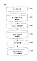
図4は、システム可視化装置400の構成例である。システム可視化装置400は、キャプチャ部410と、キャプチャデータ格納部420と、メッセージ解析部430と、プロトコルログ格納部440と、ログ分析部450と、トランザクションデータ格納部460と、を備える。
キャプチャ部410は、物理スイッチ310からパケットを受信してキャプチャデータ格納部420に格納する。メッセージ解析部430は、キャプチャデータ格納部420に格納されたパケットから所定のデータを抽出してプロトコルログ格納部440に格納する。ログ分析部450は、プロトコルログ格納部440に格納されたデータを用いてログの分析処理を実施し、トランザクションデータ格納部460に格納する。システム可視化装置400の構成についてはあくまで一例であり、他の態様を採用してもよい。
(ミラー部114、214の処理内容)
以下、ミラー部114、214が、同じ物理サーバ上のVM間で送受信されたパケットを収集する処理の内容について、より具体的に説明する。なお、ミラー部114とミラー部214は同じ処理を行うため、ミラー部114についてのみ説明する。
以下、ミラー部114、214が、同じ物理サーバ上のVM間で送受信されたパケットを収集する処理の内容について、より具体的に説明する。なお、ミラー部114とミラー部214は同じ処理を行うため、ミラー部114についてのみ説明する。
図5は、ミラー部114による処理の概要を概念的に示す図である。図5の上段に示すように、ミラー部114は、物理サーバ100が有する全てのVMが送受信するパケット(すなわちVIF111、112を通過するパケット)をキャプチャし、VM毎、上り/下り毎にパケットバッファ114Aの該当領域に格納する。具体的にミラー部114は、VM121に送信される上りパケット、VM121から他のVMに送信される下りパケット、VM122に送信される上りパケット、VM122から他のVMに送信される下りパケットと区別してパケットバッファ114Aに格納する。以下、VM121に送信される上りパケットを「VM121の上りパケット」と、VM121から他のVMに送信される下りパケットを「VM121の下りパケット」と略記する。また、VM122に送信される上りパケットを「VM122の上りパケット」と、VM122から他のVMに送信される下りパケットを「VM122の下りパケット」と略記する。
なお、図1におけるVIF111、112を通過するパケットに関して、上向きの矢印は上りパケットであることを示し、下向きの矢印は下りパケットであることを示す。
より厳密には、本実施例において上りパケットは、パケットがキャプチャされた位置であるVIFにおいて、当該VIFに対応付けられた(当該VIFがパケットの送受信を担当する)VMに近づく方向に転送されるパケットと定義することができる。
一方、下りパケットは、パケットがキャプチャされた位置であるVIFにおいて、当該VIFに対応付けられたVMから遠ざかる方向に転送されるパケットと定義することができる。
なお、パケットがキャプチャされた位置に対応付けられたVMが複数存在することも想定される(第2実施例におけるNIC130でキャプチャされた場合がその一例である)。この場合、「対応付けられたVM」を、「対応付けられた複数のVMのうちいずれか」と読み替えればよい。例えばNIC130に対応付けられるVMは、物理サーバ100上の全てのVM(121、122)であり、NIC230に対応付けられるVMは、物理サーバ200上の全てのVM(221、222)である。
図6は、ミラー部114が上りパケットであるか下りパケットであるかを判別する処理の流れを示すフローチャートである。本フローチャートは、パケットがキャプチャされる度に実行される。
まず、ミラー部114は、キャプチャしたパケットのMACヘッダにおける宛先MACアドレスと、パケットがキャプチャされた位置であるVIFに対応するVMのMACアドレスを比較する(S500)。そして、ミラー部114は、宛先MACアドレスとVMのMACアドレスが一致するか否かを判定する(S502)。
宛先MACアドレスとVMのMACアドレスが一致する場合、ミラー部114は、上りパケットと判定し、当該パケットをパケットバッファ114Aの該当領域に格納する(S504)。
宛先MACアドレスとVMのMACアドレスが一致しない場合、ミラー部114は、パケットのMACヘッダにおける送信元MACアドレスと、パケットがキャプチャされた位置であるVIFに対応するVMのMACアドレスを比較する(S506)。そして、ミラー部114は、送信元MACアドレスとVMのMACアドレスが一致するか否かを判定する(S508)。
送信元MACアドレスとVMのMACアドレスが一致する場合、ミラー部114は、下りパケットと判定し、当該パケットをパケットバッファ114Aの該当領域に格納する(S510)。
送信元MACアドレスとVMのMACアドレスが一致しない場合、ミラー部114は、エラーデータとみなして当該パケットを削除する(S512)。
なお、S504又はS510で格納されたパケットには、キャプチャされた時刻が付与される。
ミラー部114が上りパケットであるか下りパケットであるかを判別する処理は、IPヘッダに含まれる送信先アドレスや送信元アドレスを用いて行ってもよい。この場合、ミラー部114は、各VMのIPアドレスを、VIFに対応付けてテーブルデータとして保持する。
図7は、ミラー部114が上りパケットであるか下りパケットであるかを判別する処理の流れを示すフローチャートの他の例である。本フローチャートは、パケットがキャプチャされる度に実行される。
まず、ミラー部114は、キャプチャしたパケットのIPヘッダにおける送信先アドレスと、パケットがキャプチャされた位置であるVIFに対応するVMのIPアドレスを比較する(S600)。そして、ミラー部114は、送信先アドレスとVMのIPアドレスが一致するか否かを判定する(S602)。
送信先アドレスとVMのIPアドレスが一致する場合、ミラー部114は、上りパケットと判定し、当該パケットをパケットバッファ114Aの該当領域に格納する(S604)。
送信先アドレスとVMのIPアドレスが一致しない場合、ミラー部114は、キャプチャしたパケットのIPヘッダにおける送信元アドレスと、パケットがキャプチャされた位置であるVIFに対応するVMのIPアドレスを比較する(S606)。そして、ミラー部114は、送信元アドレスとVMのIPアドレスが一致するか否かを判定する(S608)。
送信元アドレスとVMのIPアドレスが一致する場合、ミラー部114は、下りパケットと判定し、当該パケットをパケットバッファ114Aの該当領域に格納する(S610)。
送信元アドレスとVMのIPアドレスが一致しない場合、ミラー部114は、エラーデータとみなして当該パケットを削除する(S612)。
なお、S604又はS610で格納されたパケットには、キャプチャされた時刻が付与される。
ミラー部114は、図6又は図7に示す処理によってパケットをパケットバッファ114Aの該当領域に格納すると、図5の下段に示すように、パケットが同一であるかどうか比較して同じ物理サーバ100上のVM間で送受信されたパケットを抽出する。パケットの比較は、VM121の上りパケットとVM122の下りパケットの組み合わせと、VM121の下りパケットとVM122の上りパケットの組み合わせのそれぞれについて行われる。
ここで、物理サーバ100上に三以上のVMが存在する場合、ミラー部114は、あるVMの上りパケットと他の全てのVMの下りパケットの比較、及び当該VMの下りパケットと他の全てのVMの上りパケットの比較を、全てのVMに対して行う。図8は、VMの数が三の場合に行われるパケット比較の組み合わせを示す図である。また、図9は、VMの数が四の場合に行われるパケット比較の組み合わせを示す図である。図8及び9において、各VMをVM1、VM2、…と表記した。このように、ミラー部114は、VMの数をnとすると、(nP2)通りのパケット比較を行う。
図10は、ミラー部114がパケット比較を行う際の処理の流れを示すフローチャートである。本フローは、例えば所定時間毎に繰り返し実行される。
まず、ミラー部114は、パケットバッファ114Aの「VM121の上りパケット」を格納した領域からパケットを順に一つ取り出し(S700)、更に「VM122の下りパケット」を格納した領域からパケットを順に一つ取り出す(S702)。パケットの取り出し順は、例えばFIFO(First In, First Out)に従って決定される。
次に、ミラー部114は、S700及びS702で取り出したパケットにおけるIPヘッダ内のIPパケットを識別する情報である「ID」、「送信元アドレス」、「送信先アドレス」を比較する(S704)。そして、ミラー部114は、IPヘッダの「ID」、「送信元アドレス」、「送信先アドレス」が全て一致しているか否かを判定する(S706)。
IPヘッダの「ID」、「送信元アドレス」、「送信先アドレス」が全て一致している場合、ミラー部114は、一致したパケット対のうちいずれかを(例えば下りパケットを)NIC132に送信する(S708)。そして、ミラー部114は、当該一致したパケット対をパケットバッファ114Aから削除する(S710)。ミラー部114は、S710の処理の後は、後述するS714に進み処理を実行する。
IPヘッダの「ID」等が全て一致しなかった場合、ミラー部114は、「VM122の下りパケット」に関するループ処理において「VM122の下りパケット」を格納した領域の全てのパケットを取り出したか否かを判定する(S712)。「VM122の下りパケット」に関するループ処理とは、S702~S710の処理を繰り返し行うループ処理である。当該ループ処理において、「VM122の下りパケット」の全てのパケットを取り出していない場合、ミラー部114は、S702に戻り、「VM122の下りパケット」から次のパケットを取り出してS704以降の処理を実行する。
「VM122の下りパケット」の全てのパケットを取り出した場合、又はS710の後、ミラー部114は、「VM121の上りパケット」に関するループ処理において「VM121の上りパケット」の全てのパケットを取り出したか否かを判定する(S714)。「VM121の上りパケット」に関するループ処理とは、S700~S712の処理を繰り返し行うループ処理である。当該ループ処理において、「VM121の上りパケット」の全てのパケットを取り出していない場合、ミラー部114は、S700に戻り、「VM121の上りパケット」から次のパケットを取り出してS702以降の処理を実行する。
「VM121の上りパケット」の全てのパケットを取り出した場合、ミラー部114は、パケットバッファ114Aの「VM121の下りパケット」を格納した領域からパケットを順に一つ取り出す(S720)。更にミラー部114は、「VM122の上りパケット」を格納した領域からパケットを順に一つ取り出す(S722)。
次に、ミラー部114は、S720及びS722で取り出したパケットにおけるIPヘッダの「ID」、「送信元アドレス」、「送信先アドレス」を比較する(S724)。そして、ミラー部114は、IPヘッダの「ID」、「送信元アドレス」、「送信先アドレス」が全て一致しているか否かを判定する(S726)。
IPヘッダの「ID」、「送信元アドレス」、「送信先アドレス」が全て一致している場合、ミラー部114は、一致したパケット対のうちパケットのうちいずれかを(例えば下りパケットを)NIC132に送信する(S728)。そして、ミラー部114は、当該一致したパケット対をパケットバッファ114Aから削除する(S730)。
IPヘッダの「ID」等が全て一致しなかった場合、ミラー部114は、「VM122の上りパケット」に関するループ処理において「VM122の上りパケット」を格納した領域の全てのパケットを取り出したか否かを判定する(S732)。「VM122の上りパケット」に関するループ処理とは、S722~S730の処理を繰り返し行うループ処理である。当該ループ処理において、「VM122の上りパケット」の全てのパケットを取り出していない場合、ミラー部114は、S722に戻り、次のパケットを取り出してS724以降の処理を実行する。
「VM122の上りパケット」の全てのパケットを取り出した場合、ミラー部114は、「VM121の下りパケット」に関するループ処理において「VM121の下りパケット」の全てのパケットを取り出したか否かを判定する(S734)。「VM121の下りパケット」に関するループ処理とは、S720~S732の処理を繰り返し行うループ処理である。当該ループ処理において、「VM121の下りパケット」の全てのパケットを取り出していない場合、ミラー部114は、S720に戻り、次のパケットを取り出してS722以降の処理を実行する。
「VM121の下りパケット」の全てのパケットを取り出した場合、ミラー部114は、パケットバッファ114Aに格納された全てのパケットのうち、キャプチャされてから一定時間経過したパケットを削除する(S740)。
なお、図10に示すフローチャートは、物理サーバ100上に存在するVMの数が二である場合についてのものである。物理サーバ100上に存在するVMの数nが三以上である場合は、S700~S714、S720~S734のようなループ処理を、(nP2)通り行えばよい。
(変形例)
ここで、変形例の情報処理システム及び物理サーバについて述べる。図11は、変形例の情報処理システム1#及び物理サーバ100#、200#を示す図である。本図においては、第1実施例の情報処理システム1及び物理サーバ100、200の対応する構成要素の符号に「#」を付している。
ここで、変形例の情報処理システム及び物理サーバについて述べる。図11は、変形例の情報処理システム1#及び物理サーバ100#、200#を示す図である。本図においては、第1実施例の情報処理システム1及び物理サーバ100、200の対応する構成要素の符号に「#」を付している。
変形例の物理サーバ100#が有するミラー部114#は、VIF111#、112#を通過する全てのパケットを収集し、NIC132#に送信する。係る構成によって、複数の仮想マシンが同一の物理サーバ内で送受信するデータを、外部装置に出力することができる。この結果、外部装置すなわちシステム可視化装置は、複数の仮想マシンが同一の物理サーバ内で送受信するデータと、物理サーバが外部装置との間で送受信するデータの双方を収集することができる。
図1に示す第1実施例の情報処理システム及び物理サーバは、変形例の情報処理システム及び物理サーバに比してNIC132のパケット転送負荷を低減することができる。変形例の物理サーバ100#ではNIC132#が「A↓B↓D↓C↑」を転送するのに対し、本実施例の物理サーバ100ではNIC132が「B↓D↓」を転送するからである。
第1実施例の情報処理システム及び物理サーバは、同じ物理サーバ上のVM間で送受信されたパケットを収集してNIC132に送信し、異なる物理サーバ間で送受信されるパケットのミラーリングは物理スイッチ300の機能に任せている。このため、NIC132におけるパケット転送負荷は過大なものとならず、スムーズな情報送受信が実現される。また、過度に高機能のNIC132を搭載する必要が無くなり、コストや重量の増加を抑制することができる。ミラー部214とNIC232の関係についても同様である。
(まとめ)
以上説明した本実施例の情報処理装置(物理サーバ)、その通信データ出力方法及びプログラム、並びに情報処理システムによれば、複数の仮想マシンが同一の物理サーバ内で送受信するデータを、外部装置に出力することができる。この結果、外部装置すなわちシステム可視化装置は、複数の仮想マシンが同一の物理サーバ内で送受信するデータと、物理サーバが外部装置との間で送受信するデータの双方を収集することができる。
以上説明した本実施例の情報処理装置(物理サーバ)、その通信データ出力方法及びプログラム、並びに情報処理システムによれば、複数の仮想マシンが同一の物理サーバ内で送受信するデータを、外部装置に出力することができる。この結果、外部装置すなわちシステム可視化装置は、複数の仮想マシンが同一の物理サーバ内で送受信するデータと、物理サーバが外部装置との間で送受信するデータの双方を収集することができる。
<第2実施例>
以下、図面を参照し、本発明の第2実施例に係る情報処理装置、通信データ出力方法、通信データ出力プログラム、並びにこれらを利用した情報処理システムについて説明する。
以下、図面を参照し、本発明の第2実施例に係る情報処理装置、通信データ出力方法、通信データ出力プログラム、並びにこれらを利用した情報処理システムについて説明する。
図12は、本発明の第2実施例に係る情報処理システム2のシステム構成例である。第2実施例に係る情報処理システム2は、ミラー部の処理内容が第1実施例と異なる。このため、ミラー部114*、214*と表記すると共に、それぞれが使用するパケットバッファをパケットバッファ114*A、214*Aと表記し、その他の構成要素については第1実施例と同じ符号を付して説明する。
(ミラー部114*、214*の処理内容)
以下、ミラー部114*、214*が、同じ物理サーバ上のVM間で送受信されたパケットを収集する処理の内容について、より具体的に説明する。なお、ミラー部114*とミラー部214*は同じ処理を行うため、ミラー部114*についてのみ説明する。
以下、ミラー部114*、214*が、同じ物理サーバ上のVM間で送受信されたパケットを収集する処理の内容について、より具体的に説明する。なお、ミラー部114*とミラー部214*は同じ処理を行うため、ミラー部114*についてのみ説明する。
図13は、ミラー部114*による処理の概要を概念的に示す図である。図13の上段に示すように、ミラー部114*は、物理サーバ100が有する全てのVMが送受信する下りパケット、及びNIC130を通過する下りパケットをキャプチャし、パケットバッファ114*Aの該当領域に格納する。具体的にミラー部114*は、VM121から他のVMに送信される下りパケット、VM122から他のVMに送信される下りパケット、NIC130から物理スイッチ300に転送される下りパケットと区別してパケットバッファ114*Aに格納する。以下、VM121から他のVMに送信される下りパケットを「VM121の下りパケット」と、VM122から他のVMに送信される下りパケットを「VM122の下りパケット」と略記する。また、NIC130から物理スイッチ300に送信される下りパケットを「NIC130の下りパケット」と略記する。
本実施例において、NIC130においてキャプチャされた「上りパケット」は、NIC130が外部装置(物理スイッチ300)から受信するパケットであり、「下りパケット」は、NIC130が外部装置(物理スイッチ300)に送信するパケットである。
上記のように、ミラー部114*は、下りパケットを選択的に収集する。図14は、ミラー部114*が下りパケットを選択的に収集する処理の流れを示すフローチャートである。本フローチャートは、ミラー部114*によりパケットがキャプチャされる度に実行される。
まず、ミラー部114*は、VIF111又はVIF112でキャプチャされたパケットであるか否かを判定する(S800)。
VIF111又はVIF112でキャプチャされたパケットである場合、ミラー部114*は、以下の処理を行う。ミラー部114*は、キャプチャしたパケットのMACヘッダにおける送信元MACアドレスと、パケットがキャプチャされた位置であるVIFに対応するVMのMACアドレスを比較する(S802)。そして、ミラー部114*は、送信元MACアドレスとVMのMACアドレスが一致するか否かを判定する(S804)。
送信元MACアドレスとVMのMACアドレスが一致する場合、ミラー部114*は、下りパケットと判定し、当該パケットをパケットバッファ114*Aの該当領域に格納する(S806)。
送信元MACアドレスとVMのMACアドレスが一致しない場合、ミラー部114*は、上りパケット又はエラーデータとみなして当該パケットを削除する(S808)。
一方、S800において、VIF111又はVIF112でキャプチャされたパケットでない、すなわちNIC130でキャプチャされたパケットであると判定された場合、ミラー部114*は、以下の処理を行う。
まず、ミラー部114*は、送信元MACアドレスと、物理サーバ100が有する全てのVM(121、122)のMACアドレスを比較する(S810)。そして、ミラー部114*は、送信元MACアドレスがいずれかのVMのMACアドレスと一致するか否かを判定する(S812)。
送信元MACアドレスがいずれかのVMのMACアドレスと一致する場合、ミラー部114*は、下りパケットと判定し、当該パケットをパケットバッファ114*Aの該当領域に格納する(S814)。
送信元MACアドレスが全てのVMのMACアドレスと一致しない場合、ミラー部114*は、上りパケット又はエラーデータとみなして当該パケットを削除する(S808)。
なお、S806又はS814で格納されたパケットには、キャプチャされた時刻が付与される。
図15は、ミラー部114*が下りパケットを選択的に収集する処理の流れを示すフローチャートの他の例である。本フローチャートは、ミラー部114*によりパケットがキャプチャされる度に実行される。
まず、ミラー部114*は、VIF111又はVIF112でキャプチャされたパケットであるか否かを判定する(S900)。
VIF111又はVIF112でキャプチャされたパケットである場合、ミラー部114*は、以下の処理を行う。ミラー部114*は、キャプチャしたパケットのIPヘッダにおける送信元アドレスと、パケットがキャプチャされた位置であるVIFに対応するVMのIPアドレスを比較する(S902)。そして、ミラー部114*は、送信元アドレスとVMのIPアドレスが一致するか否かを判定する(S904)。
送信元アドレスとVMのIPアドレスが一致する場合、ミラー部114*は、下りパケットと判定し、当該パケットをパケットバッファ114*Aの該当領域に格納する(S906)。
送信元CアドレスとVMのIPアドレスが一致しない場合、ミラー部114*は、上りパケット又はエラーデータとみなして当該パケットを削除する(S908)。
一方、S900において、VIF111又はVIF112でキャプチャされたパケットでない、すなわちNIC130でキャプチャされたパケットであると判定された場合、ミラー部114*は、以下の処理を行う。ミラー部114*は、キャプチャしたパケットのIPヘッダにおける送信元アドレスと、物理サーバ100が有する全てのVM(121、122)のIPアドレスを比較する(S910)。そして、ミラー部114*は、送信元アドレスがいずれかのVMのIPアドレスと一致するか否かを判定する(S912)。
送信元アドレスがいずれかのVMのIPアドレスと一致する場合、ミラー部114*は、下りパケットと判定し、当該パケットをパケットバッファ114*Aの該当領域に格納する(S914)。
送信元アドレスが全てのVMのIPアドレスと一致しない場合、ミラー部114*は、上りパケット又はエラーデータとみなして当該パケットを削除する(S908)。
なお、S906又はS914で格納されたパケットには、キャプチャされた時刻が付与される。
ミラー部114*は、パケットをパケットバッファ114*Aの該当領域に格納すると、図13の下段に示すように、パケットが同一であるかどうか比較して同じ物理サーバ100上のVM間で送受信されたパケットを抽出する。パケットの比較は、VM121の下りパケットとNIC130を通過する下りパケットの組み合わせと、VM122の下りパケットとNIC130を通過する下りパケットの組み合わせのそれぞれについて行われる。
図16は、ミラー部114*がパケット比較を行う際の処理の流れを示すフローチャートである。本フローは、例えば所定時間毎に繰り返し実行される。
まず、ミラー部114*は、パケットバッファ114*Aの「VM121の下りパケット」を格納した領域からパケットを順に一つ取り出し(S1000)、「NIC130の下りパケット」を格納した領域からパケットを順に一つ取り出す(S1002)。パケットの取り出し順は、例えばFIFO(First In, First Out)に従って決定される。
次に、ミラー部114*は、S1000及びS1002で取り出したパケットにおけるIPヘッダの「ID」、「送信元アドレス」、「送信先アドレス」を比較する(S1004)。そして、ミラー部114*は、IPヘッダの「ID」、「送信元アドレス」、「送信先アドレス」が全て一致しているか否かを判定する(S1006)。
IPヘッダの「ID」、「送信元アドレス」、「送信先アドレス」が全て一致している場合、ミラー部114*は、当該パケット対をパケットバッファ114*Aから削除する(S1008)。ミラー部114*は、S1008の処理の後は、後述するS1012に進み処理を実行する。
IPヘッダの「ID」等が全て一致しなかった場合、ミラー部114*は、「NIC130の下りパケット」に関するループ処理において「NIC130の下りパケット」を格納した領域の全てのパケットを取り出したか否かを判定する(S1010)。「NIC130の下りパケット」に関するループ処理とは、S1002~S1008の処理を繰り返し行うループ処理である。当該ループ処理において、「NIC130の下りパケット」の全てのパケットを取り出していない場合、ミラー部114*は、S1002に戻り、「NIC130の下りパケット」から次のパケットを取り出してS1004以降の処理を実行する。
「NIC130の下りパケット」の全てのパケットを取り出した場合、又はS1008の後、ミラー部114*は、以下の処理を行う。ミラー部114*は、「VM121の下りパケット」に関するループ処理において「VM121の下りパケット」の全てのパケットを取り出したか否かを判定する(S1012)。「VM121の下りパケット」に関するループ処理とは、S1000~S1010の処理を繰り返し行うループ処理である。当該ループ処理において、「VM121の下りパケット」の全てのパケットを取り出していない場合、ミラー部114*は、S1000に戻り、「VM121の下りパケット」から次のパケットを取り出してS1002以降の処理を実行する。
「VM121の下りパケット」の全てのパケットを取り出した場合、ミラー部114*は、パケットバッファ114*Aの「VM122の下りパケット」を格納した領域からパケットを順に一つ取り出す(S1020)。次に、ミラー部114*は、「NIC130の下りパケット」を格納した領域からパケットを順に一つ取り出す(S1022)。
次に、ミラー部114*は、S1020及びS1022で取り出したパケットにおけるIPヘッダの「ID」、「送信元アドレス」、「送信先アドレス」を比較する(S1024)。そして、ミラー部114*は、IPヘッダの「ID」、「送信元アドレス」、「送信先アドレス」が全て一致しているか否かを判定する(S1026)。
IPヘッダの「ID」、「送信元アドレス」、「送信先アドレス」が全て一致している場合、ミラー部114*は、当該パケット対をパケットバッファ114*Aから削除する(S1028)。ミラー部114*は、S1028の処理の後は、後述するS1012に進み処理を実行する。
IPヘッダの「ID」等が全て一致しなかった場合、ミラー部114*は、「NIC130の下りパケット」に関するループ処理において「NIC130の下りパケット」を格納した領域の全てのパケットを取り出したか否かを判定する(S1030)。「NIC130の下りパケット」に関するループ処理とは、S1022~S1028の処理を繰り返し行うループ処理である。当該ループ処理において、「NIC130の下りパケット」の全てのパケットを取り出していない場合、ミラー部114*は、S1022に戻り、「NIC130の下りパケット」から次のパケットを取り出してS1024以降の処理を実行する。
「NIC130の下りパケット」の全てのパケットを取り出した場合、又はS1028の後、ミラー部114*は以下の処理を行う。ミラー部114*は、「VM122の下りパケット」に関するループ処理において「VM122の下りパケット」の全てのパケットを取り出したか否かを判定する(S1032)。「VM122の下りパケット」に関するループ処理とは、S1020~S1030の処理を繰り返し行うループ処理である。「VM122の下りパケット」の全てのパケットを取り出していない場合、ミラー部114*は、S1020に戻り、「VM122の下りパケット」から次のパケットを取り出してS1022以降の処理を実行する。
「VM122の下りパケット」の全てのパケットを取り出した場合、ミラー部114*は、パケットバッファ114*Aに格納された全てのパケットのうち、キャプチャされてから一定時間経過したパケットをNIC132に送信する(S1040)。
なお、図16に示すフローチャートは、物理サーバ100上に存在するVMの数が二である場合についてのものである。物理サーバ100上に存在するVMの数nが三以上である場合は、ミラー部114*は、S1000~S1012、S1020~S1032のようなループ処理を、(nP2)通り行えばよい。
本実施例と、図11に示す変形例の情報処理システム1#及び物理サーバ100#、200#との相違点については、第1実施例と同様であるため、説明を省略する。
(まとめ)
以上説明した本実施例の情報処理装置(物理サーバ)、その通信データ出力方法及びプログラム、並びに情報処理システムによれば、複数の仮想マシンが同一の物理サーバ内で送受信するデータを、外部装置に出力することができる。この結果、外部装置すなわちシステム可視化装置は、複数の仮想マシンが同一の物理サーバ内で送受信するデータと、物理サーバが外部装置との間で送受信するデータの双方を収集することができる。
以上説明した本実施例の情報処理装置(物理サーバ)、その通信データ出力方法及びプログラム、並びに情報処理システムによれば、複数の仮想マシンが同一の物理サーバ内で送受信するデータを、外部装置に出力することができる。この結果、外部装置すなわちシステム可視化装置は、複数の仮想マシンが同一の物理サーバ内で送受信するデータと、物理サーバが外部装置との間で送受信するデータの双方を収集することができる。
また、第1実施例と比較すると、キャプチャを行う位置は増加するものの、パケットバッファ114*Aにおいて、キャプチャしたパケットを格納する領域数を少なくすることができる(図5、13参照)。
<第3実施例>
以下、図面を参照し、本発明の第3実施例に係る情報処理装置、通信データ出力方法、通信データ出力プログラム、並びにこれらを利用した情報処理システムについて説明する。(以下、下線省略)
図17は、本発明の第3実施例に係る情報処理システム3のシステム構成例である。第3実施例に係る情報処理システム3は、各物理サーバ100、200のホストOS110、120がそれぞれ、MACアドレステーブル115、125を備える。MACアドレステーブル115は、補助記憶装置100D又はメモリ装置100E上に設定されるテーブルデータである。同様に、MACアドレステーブル215は、補助記憶装置200D又はメモリ装置200E上に設定されるテーブルデータである。
また、本発明の第3実施例に係る情報処理システム3は、ブリッジ及びミラー部の処理内容が第1実施例と異なる。このため、図17では、ブリッジ113**、213**、ミラー部114**、214**と表記すると共に、その他の構成要素については第1実施例と同じ符号を付した。
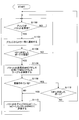
図18は、第3実施例に係るブリッジ113**及びミラー部114**、又はブリッジ213**及びミラー部214**により実行される処理の流れを示すフローチャートである。以下、ブリッジ113**及びミラー部114**による処理であるものとして説明するが、ブリッジ213**及びミラー部214**によっても同様の処理が行われる。
まず、ブリッジ113**が、VIF111又は112、或いはNIC130からパケットを受信するまで待機する(S1100)。パケットを受信すると、ブリッジ113**は、ミラー部114**にその旨を通知する(S1102)。
ミラー部114**は、上記通知を受けると、受信したのが、ブリッジ113**の仮想的なポートのうちVIF111又は112に対応したポートであるか否かを判定する(S1104)。
受信したのが、ブリッジ113**の仮想的なポートのうち、VIF111又は112に対応したポートでない場合、ミラー部114**は、S1100に戻りブリッジ113**がパケットを受信するまで待機する。
受信したのが、ブリッジ113**の仮想的なポートのうち、VIF111又は112に対応したポートである場合、ミラー部114**は、パケットの送信先MACアドレスを用いてMACアドレステーブル115を検索する(S1106)。
図19は、MACアドレステーブル115として格納されるデータの一例である。MACアドレステーブル115には、仮想的なポートに対して、ブリッジ113**により学習されたMACアドレス(学習MACヘッダアドレス)が対応付けられて格納される。
ミラー部114**は、パケットの送信先MACアドレスが、MACアドレステーブル115に登録されているか否かを判定する(S1108)。
パケットの送信先MACアドレスが、MACアドレステーブル115に登録されていない場合、ミラー部114**は、当該パケットをブリッジ113**からコピーし、コピーしたパケットをNIC132に送信する(S1110)。なお、ブリッジ113**は、受信したパケットの送信元MACアドレスを、パケットを受信した仮想的なポートに対応付けてMACアドレステーブル115に登録する機能を有する。
MACアドレステーブル115に登録されている場合、ミラー部114**は、MACアドレステーブル115において送信先MACアドレスに対応するポートがVIF111又は112に対応するポートであるか否かを判定する(S1112)。
MACアドレステーブル115において送信先MACアドレスに対応するポートがVIF111又は112に対応するポートでない場合、ミラー部114**は、S1100に戻りブリッジ113**がパケットを受信するまで待機する。
一方、VIF111又は112に対応するポートである場合、ミラー部114**は、当該パケットをブリッジ113**からコピーし、コピーしたパケットをNIC132に送信する(S1110)。
係る処理の結果、図17に示すパケットBがVM121からVM122に送信される場合、パケットBの送信先MACアドレスであるVM122のMACアドレスがMACアドレステーブル115に登録されていれば、NIC132にパケットBが送信される。また、VM122のMACアドレスがMACアドレステーブル115に登録されていない場合も同様に、NIC132にパケットBが送信される。後者の場合、VM122のMACアドレスはMACアドレステーブル115に登録されることになるため、以降の処理においてはS1112において肯定的な判定を得ることにより、NIC132にパケットが送信される。
一方、図17に示すパケットAがVM121からVM221に送信される場合について説明する。この場合、パケットAの送信MACアドレスであるVM223のMACアドレスがMACアドレステーブル115に登録されていれば、ポートがNIC130に対応するためNIC132にパケットAが送信されない。パケットAの送信MACアドレスであるVM223のMACアドレスがMACアドレステーブル115に登録されていない場合は、NIC132にパケットAが送信される。この場合、物理スイッチ300においてもパケットAがミラーリングされるため、システム可視化装置400にはパケットAが重複して送信されるが、以降はMACアドレステーブル115に登録されことになるため、係る重複は許容できる範囲内である。
同様に、パケットCがVM221からVM121に送信される場合、パケットCはブリッジ113**におけるNIC130に対応するポートで受信されるため、NIC132にパケットCが送信されない。
本実施例と、図11に示す変形例の情報処理システム1#及び物理サーバ100#、200#との相違点については、第1実施例と同様であるため、説明を省略する。
(まとめ)
以上説明した本実施例の情報処理装置(物理サーバ)、その通信データ出力方法及びプログラム、並びに情報処理システムによれば、複数の仮想マシンが同一の物理サーバ内で送受信するデータを、外部装置に出力することができる。この結果、外部装置すなわちシステム可視化装置は、複数の仮想マシンが同一の物理サーバ内で送受信するデータと、物理サーバが外部装置との間で送受信するデータの双方を収集することができる。
以上説明した本実施例の情報処理装置(物理サーバ)、その通信データ出力方法及びプログラム、並びに情報処理システムによれば、複数の仮想マシンが同一の物理サーバ内で送受信するデータを、外部装置に出力することができる。この結果、外部装置すなわちシステム可視化装置は、複数の仮想マシンが同一の物理サーバ内で送受信するデータと、物理サーバが外部装置との間で送受信するデータの双方を収集することができる。
なお、第3実施例の情報処理装置は、第1実施例と同様、MACアドレスに代えてIPアドレスを用いてパケットの収集を行ってもよい。
(以上、追加実施例)
以上、本発明を実施するための最良の形態について実施例を用いて説明したが、本発明はこうした実施例に何等限定されるものではなく、本発明の要旨を逸脱しない範囲内において種々の変形及び置換を加えることができる。
以上、本発明を実施するための最良の形態について実施例を用いて説明したが、本発明はこうした実施例に何等限定されるものではなく、本発明の要旨を逸脱しない範囲内において種々の変形及び置換を加えることができる。
例えば、第2実施例におけるミラー部114*は、全てのVMが送受信する下りパケット、及びNIC130を通過する下りパケットをキャプチャし、内容が一致するものを除外するものとしたが、これに限られない。第2実施例におけるミラー部114*は、全てのVMが送受信する上りパケット、及びNIC130を通過する上りパケットをキャプチャし、内容が一致するものを除外してNIC132にパケットを送信するものとしてもよい。
また、物理スイッチ300、310は、統合されて同体の物理スイッチとなってもよい。
また、各実施例におけるOSやVMの配置は任意事項であり、情報処理装置(物理サーバ)上に複数のVMが存在すれば、本発明の適用は可能である。
また、各物理サーバは、外部装置との送受信を行うNICとミラー部が収集したパケットを送信するNICを分けるものとしたが、同一のNICで外部装置との送受信パケットとミラー部が収集したパケットの双方を扱うものとしてもよい。この場合、ミラー部が収集したパケットを他のパケットと区別可能な態様でミラー部が収集したパケットを送信すると好適である。例えば、ミラー部が収集したパケットを送信する期間と、他のパケットを送受信する期間を分けることや、ミラー部が収集したパケットには所定の識別子を付すこと等が考えられる。
本発明は、コンピュータ製造業、コンピュータソフトウエア産業、情報サービス提供産業等に利用することができる。
1、2 情報処理システム
100、200 物理サーバ
110、210 ホストOS
111、112、211、212 VIF
113、113**、213、213** ブリッジ
114、114*、114**、214、214*、214** ミラー部
114A、114*A、214A、214*A パケットバッファ
115 MACアドレステーブル
120、220 ゲストOS
121、122、221、222 VM
123、124、223、224 仮想NIC
130、132 NIC
300、310 物理スイッチ
400 システム可視化装置
100、200 物理サーバ
110、210 ホストOS
111、112、211、212 VIF
113、113**、213、213** ブリッジ
114、114*、114**、214、214*、214** ミラー部
114A、114*A、214A、214*A パケットバッファ
115 MACアドレステーブル
120、220 ゲストOS
121、122、221、222 VM
123、124、223、224 仮想NIC
130、132 NIC
300、310 物理スイッチ
400 システム可視化装置
Claims (23)
- 物理装置内で実行される複数の仮想マシンが、同一の物理装置内で送受信するデータを収集するデータ収集部と、
前記データ収集部により収集されたデータを外部装置に出力する通信部と、
を備える情報処理装置。 - 前記データ収集部は、前記複数の仮想マシンが同一の物理装置内で送受信するデータを、前記複数の仮想マシンが外部装置との間で送受信するデータと区別して収集することを特徴とする、
請求項1記載の情報処理装置。 - 前記通信部とは異なる第2の通信部であって、前記複数の仮想マシンが外部装置との間で送受信するデータの入出力を行う第2の通信部を備える、
請求項2記載の情報処理装置。 - 前記データ収集部は、第1の観測位置で観測されたデータであって該第1の観測位置において該第1の観測位置に対応付けられた仮想マシンに近づく方向に転送されるデータと、第2の観測位置で観測されたデータであって該第2の観測位置において該第2の観測位置に対応付けられた仮想マシンから遠ざかる方向に転送されるデータと、の組み合わせのうち特定のデータ内容が一致するデータを、前記複数の仮想マシンが同一の物理装置内で送受信するデータと判断して収集することを特徴とする、
請求項2記載の情報処理装置。 - 前記データ収集部は、所定の観測位置で観測されたデータであって該所定の観測位置において該所定の観測位置に対応付けられた仮想マシンから遠ざかる方向に転送されるデータと、前記第2の通信部が外部装置に送信するデータと、を取得し、該取得したデータのうち特定のデータ内容が一致するデータの対を除外した残余のデータを、前記複数の仮想マシンが同一の物理装置内で送受信するデータと判断して収集することを特徴とする、
請求項3記載の情報処理装置。 - 前記データ収集部は、所定の観測位置で観測されたデータであって該所定の観測位置において該所定の観測位置に対応付けられた仮想マシンに近づく方向に転送されるデータと、前記第2の通信部が外部装置から受信するデータと、を取得し、該取得したデータのうち特定のデータ内容が一致するデータの対を除外した残余のデータを、前記複数の仮想マシンが同一の物理装置内で送受信するデータと判断して収集することを特徴とする、
請求項3記載の情報処理装置。 - 前記データ収集部は、前記複数の仮想マシンと外部装置の間を中継する中継部がデータを受信したとき、該中継部の仮想的な受信ポートと、仮想的な送信ポートの双方が前記複数の仮想マシン側に対応付けられている場合に、該中継部が受信したデータを前記複数の仮想マシンが同一の物理装置内で送受信するデータと判断して収集することを特徴とする、
請求項2記載の情報処理装置。 - 請求項3記載の情報処理装置と、
前記第2の通信部との間で送受信したデータのコピーと、前記通信部から受信したデータとを出力するスイッチと、
を備える情報処理システム。 - 前記スイッチは、
前記第2の通信部との間でデータの送受信を行うと共に、該送受信したデータのコピーを第2のスイッチに送信する第1のスイッチと、
前記第1のスイッチから受信したデータと、前記通信部から受信したデータとを合わせて出力する前記第2のスイッチと、
を備えることを特徴とする、
請求項8記載の情報処理システム。 - 物理装置内で複数の仮想マシンが実行される情報処理装置の通信データ出力方法であって、
前記情報処理装置が、
前記複数の仮想マシンが同一の物理装置内で送受信するデータを収集し、
前記収集されたデータを外部装置に出力する、
通信データ出力方法。 - 前記収集する処理は、前記複数の仮想マシンが同一の物理装置内で送受信するデータを、前記複数の仮想マシンが外部装置との間で送受信するデータと区別して収集する処理であることを特徴とする、
請求項10記載の通信データ出力方法。 - 前記出力する処理は、前記複数の仮想マシンが外部装置との間で送受信するデータの入出力を行う第2の通信部とは異なる通信部を用いて前記収集されたデータを外部装置に出力する処理であることを特徴とする、
請求項11記載の通信データ出力方法。 - 前記収集する処理は、第1の観測位置で観測されたデータであって該第1の観測位置において該第1の観測位置に対応付けられた仮想マシンに近づく方向に転送されるデータと、第2の観測位置で観測されたデータであって該第2の観測位置において該第2の観測位置に対応付けられた仮想マシンから遠ざかる方向に転送されるデータと、の組み合わせのうち特定のデータ内容が一致するデータを、前記複数の仮想マシンが同一の物理装置内で送受信するデータと判断して収集する処理である、
請求項11記載の通信データ出力方法。 - 前記収集する処理は、所定の観測位置で観測されたデータであって該所定の観測位置において該所定の観測位置に対応付けられた仮想マシンから遠ざかる方向に転送されるデータと、前記第2の通信部が外部装置に送信するデータと、を取得し、該取得したデータのうち特定のデータ内容が一致するデータの対を除外した残余のデータを、前記複数の仮想マシンが同一の物理装置内で送受信するデータと判断して収集する処理である、
請求項12記載の通信データ出力方法。 - 前記収集する処理は、所定の観測位置で観測されたデータであって該所定の観測位置において該所定の観測位置に対応付けられた仮想マシンに近づく方向に転送されるデータと、前記第2の通信部が外部装置から受信するデータと、を取得し、該取得したデータのうち特定のデータ内容が一致するデータの対を除外した残余のデータを、前記複数の仮想マシンが同一の物理装置内で送受信するデータと判断して収集する処理であることを特徴とする、
請求項12記載の通信データ出力方法。 - 前記収集する処理は、前記複数の仮想マシンと外部装置の間を中継する中継部がデータを受信したとき、該中継部の仮想的な受信ポートと、仮想的な送信ポートの双方が前記複数の仮想マシン側に対応付けられている場合に、該中継部が受信したデータを前記複数の仮想マシンが同一の物理装置内で送受信するデータと判断して収集する処理であることを特徴とする、
請求項11記載の通信データ出力方法。 - 物理装置内で複数の仮想マシンが実行される情報処理装置の通信データ出力プログラムであって、
前記情報処理装置に、
前記複数の仮想マシンが、同一の物理装置内で送受信するデータを収集させ、
前記収集されたデータを外部装置に出力させる、
通信データ出力プログラム。 - 前記収集する処理は、前記複数の仮想マシンが同一の物理装置内で送受信するデータを、前記複数の仮想マシンが外部装置との間で送受信するデータと区別して収集する処理であることを特徴とする、
請求項17記載の通信データ出力プログラム。 - 前記出力する処理は、前記複数の仮想マシンが外部装置との間で送受信するデータの入出力を行う第2の通信部とは異なる通信部を用いて前記収集されたデータを外部装置に出力する処理であることを特徴とする、
請求項18記載の通信データ出力プログラム。 - 前記収集する処理は、第1の観測位置で観測されたデータであって該第1の観測位置において該第1の観測位置に対応付けられた仮想マシンに近づく方向に転送されるデータと、第2の観測位置で観測されたデータであって該第2の観測位置において該第2の観測位置に対応付けられた仮想マシンから遠ざかる方向に転送されるデータと、の組み合わせのうち特定のデータ内容が一致するデータを、前記複数の仮想マシンが同一の物理装置内で送受信するデータと判断して収集する処理である、
請求項18記載の通信データ出力プログラム。 - 前記収集する処理は、所定の観測位置で観測されたデータであって該所定の観測位置において該所定の観測位置に対応付けられた仮想マシンから遠ざかる方向に転送されるデータと、前記第2の通信部が外部装置に送信するデータと、を取得し、該取得したデータのうち特定のデータ内容が一致するデータの対を除外した残余のデータを、前記複数の仮想マシンが同一の物理装置内で送受信するデータと判断して収集する処理である、
請求項19記載の通信データ出力プログラム。 - 前記収集する処理は、所定の観測位置で観測されたデータであって該所定の観測位置において該所定の観測位置に対応付けられた仮想マシンに近づく方向に転送されるデータと、前記第2の通信部が外部装置から受信するデータと、を取得し、該取得したデータのうち特定のデータ内容が一致するデータの対を除外した残余のデータを、前記複数の仮想マシンが同一の物理装置内で送受信するデータと判断して収集する処理であることを特徴とする、
請求項19記載の通信データ出力プログラム。 - 前記収集する処理は、前記複数の仮想マシンと外部装置の間を中継する中継部がデータを受信したとき、該中継部の仮想的な受信ポートと、仮想的な送信ポートの双方が前記複数の仮想マシン側に対応付けられている場合に、該中継部が受信したデータを前記複数の仮想マシンが同一の物理装置内で送受信するデータと判断して収集する処理であることを特徴とする、
請求項18記載の通信データ出力プログラム。
Priority Applications (4)
| Application Number | Priority Date | Filing Date | Title |
|---|---|---|---|
| EP12866923.1A EP2809035A4 (en) | 2012-01-27 | 2012-01-27 | INFORMATION PROCESSING DEVICE, INFORMATION PROCESSING SYSTEM, COMMUNICATION DATA DELIVERY METHOD, AND COMMUNICATION DATA DELIVERY PROGRAM |
| JP2013555095A JP5825360B2 (ja) | 2012-01-27 | 2012-01-27 | 情報処理装置、情報処理システム、通信データ出力方法、及び通信データ出力プログラム |
| PCT/JP2012/051880 WO2013111343A1 (ja) | 2012-01-27 | 2012-01-27 | 情報処理装置、情報処理システム、通信データ出力方法、及び通信データ出力プログラム |
| US14/322,979 US9703580B2 (en) | 2012-01-27 | 2014-07-03 | Information processing apparatus, information processing system, and communication data output method |
Applications Claiming Priority (1)
| Application Number | Priority Date | Filing Date | Title |
|---|---|---|---|
| PCT/JP2012/051880 WO2013111343A1 (ja) | 2012-01-27 | 2012-01-27 | 情報処理装置、情報処理システム、通信データ出力方法、及び通信データ出力プログラム |
Related Child Applications (1)
| Application Number | Title | Priority Date | Filing Date |
|---|---|---|---|
| US14/322,979 Continuation US9703580B2 (en) | 2012-01-27 | 2014-07-03 | Information processing apparatus, information processing system, and communication data output method |
Publications (1)
| Publication Number | Publication Date |
|---|---|
| WO2013111343A1 true WO2013111343A1 (ja) | 2013-08-01 |
Family
ID=48873104
Family Applications (1)
| Application Number | Title | Priority Date | Filing Date |
|---|---|---|---|
| PCT/JP2012/051880 WO2013111343A1 (ja) | 2012-01-27 | 2012-01-27 | 情報処理装置、情報処理システム、通信データ出力方法、及び通信データ出力プログラム |
Country Status (4)
| Country | Link |
|---|---|
| US (1) | US9703580B2 (ja) |
| EP (1) | EP2809035A4 (ja) |
| JP (1) | JP5825360B2 (ja) |
| WO (1) | WO2013111343A1 (ja) |
Cited By (2)
| Publication number | Priority date | Publication date | Assignee | Title |
|---|---|---|---|---|
| WO2018179413A1 (ja) * | 2017-03-31 | 2018-10-04 | 三菱電機株式会社 | 情報処理装置および情報処理方法 |
| US12076537B2 (en) | 2018-12-18 | 2024-09-03 | Sanofi | Injection device and detector arrangement |
Families Citing this family (5)
| Publication number | Priority date | Publication date | Assignee | Title |
|---|---|---|---|---|
| JP6041636B2 (ja) * | 2012-11-26 | 2016-12-14 | キヤノン株式会社 | 情報処理装置、情報処理装置の制御方法、及びプログラム |
| US9262090B2 (en) * | 2013-02-26 | 2016-02-16 | Lenovo Enterprise Solutions (Singapore) Pte. Ltd. | Asynchronous data mirroring in memory controller |
| KR102209525B1 (ko) * | 2014-01-06 | 2021-01-29 | 삼성전자주식회사 | 마이크로 서버, mac 주소 할당 방법 및 컴퓨터 판독가능 기록매체 |
| JP6248763B2 (ja) * | 2014-03-31 | 2017-12-20 | 富士通株式会社 | キャプチャポイント決定方法、キャプチャポイント決定システムおよびキャプチャポイント決定プログラム |
| JP7003562B2 (ja) * | 2017-10-16 | 2022-01-20 | 富士通株式会社 | ミラーパケット制御プログラム、ミラーパケット制御方法、およびミラーパケット制御装置 |
Citations (3)
| Publication number | Priority date | Publication date | Assignee | Title |
|---|---|---|---|---|
| JP2011182211A (ja) | 2010-03-02 | 2011-09-15 | Fujitsu Ltd | バッファ管理プログラム及び方法、並びにメッセージ分析装置 |
| JP2012004781A (ja) * | 2010-06-16 | 2012-01-05 | Fujitsu Ltd | 構成情報取得方法、仮想プローブおよび構成情報取得制御装置 |
| JP2012048629A (ja) * | 2010-08-30 | 2012-03-08 | Fujitsu Ltd | 仮想マシン管理プログラム、仮想マシン管理方法、および仮想マシン管理装置 |
Family Cites Families (15)
| Publication number | Priority date | Publication date | Assignee | Title |
|---|---|---|---|---|
| US6041042A (en) * | 1997-05-27 | 2000-03-21 | Cabletron Systems, Inc. | Remote port mirroring system and method thereof |
| US7782784B2 (en) * | 2003-01-10 | 2010-08-24 | Cisco Technology, Inc. | Port analyzer adapter |
| US7626938B1 (en) * | 2005-03-31 | 2009-12-01 | Marvell Israel (M.I.S.L) Ltd. | Local area network switch using control plane packet mirroring to support multiple network traffic analysis devices |
| JP4570527B2 (ja) * | 2005-07-20 | 2010-10-27 | 富士通株式会社 | システム性能監視プログラム及びシステム性能監視方法 |
| US8050185B2 (en) * | 2005-08-24 | 2011-11-01 | Hewlett-Packard Development Company, L.P. | Sampling of network traffic based on CAM lookup |
| US8397284B2 (en) * | 2006-01-17 | 2013-03-12 | University Of Maryland | Detection of distributed denial of service attacks in autonomous system domains |
| US20070266433A1 (en) * | 2006-03-03 | 2007-11-15 | Hezi Moore | System and Method for Securing Information in a Virtual Computing Environment |
| JP5217886B2 (ja) * | 2008-10-14 | 2013-06-19 | 富士通株式会社 | ループバック装置及びミラーリング方法 |
| WO2010099407A1 (en) * | 2009-02-27 | 2010-09-02 | Broadcom Corporation | Method and system for virtual machine networking |
| US8265075B2 (en) * | 2009-03-16 | 2012-09-11 | International Business Machines Corporation | Method and apparatus for managing, configuring, and controlling an I/O virtualization device through a network switch |
| EP3699758B1 (en) * | 2010-02-04 | 2021-08-18 | Telefonaktiebolaget LM Ericsson (publ) | Network performance monitor for virtual machines |
| US8520540B1 (en) * | 2010-07-30 | 2013-08-27 | Cisco Technology, Inc. | Remote traffic monitoring through a network |
| US9191327B2 (en) * | 2011-02-10 | 2015-11-17 | Varmour Networks, Inc. | Distributed service processing of network gateways using virtual machines |
| US9110703B2 (en) * | 2011-06-07 | 2015-08-18 | Hewlett-Packard Development Company, L.P. | Virtual machine packet processing |
| CN102870377A (zh) * | 2012-06-30 | 2013-01-09 | 华为技术有限公司 | 虚拟端口监控方法和设备 |
-
2012
- 2012-01-27 JP JP2013555095A patent/JP5825360B2/ja not_active Expired - Fee Related
- 2012-01-27 EP EP12866923.1A patent/EP2809035A4/en not_active Withdrawn
- 2012-01-27 WO PCT/JP2012/051880 patent/WO2013111343A1/ja active Application Filing
-
2014
- 2014-07-03 US US14/322,979 patent/US9703580B2/en active Active
Patent Citations (3)
| Publication number | Priority date | Publication date | Assignee | Title |
|---|---|---|---|---|
| JP2011182211A (ja) | 2010-03-02 | 2011-09-15 | Fujitsu Ltd | バッファ管理プログラム及び方法、並びにメッセージ分析装置 |
| JP2012004781A (ja) * | 2010-06-16 | 2012-01-05 | Fujitsu Ltd | 構成情報取得方法、仮想プローブおよび構成情報取得制御装置 |
| JP2012048629A (ja) * | 2010-08-30 | 2012-03-08 | Fujitsu Ltd | 仮想マシン管理プログラム、仮想マシン管理方法、および仮想マシン管理装置 |
Non-Patent Citations (2)
| Title |
|---|
| See also references of EP2809035A4 |
| SHUICHIRO AIBA ET AL.: "Traffic Control of Virtual Machine using Flow-based Analysis", IEICE TECHNICAL REPORT, ICM2010-36, vol. 110, no. 375, 13 January 2011 (2011-01-13), pages 17 - 22, XP008171913 * |
Cited By (3)
| Publication number | Priority date | Publication date | Assignee | Title |
|---|---|---|---|---|
| WO2018179413A1 (ja) * | 2017-03-31 | 2018-10-04 | 三菱電機株式会社 | 情報処理装置および情報処理方法 |
| US10715433B2 (en) | 2017-03-31 | 2020-07-14 | Mitsubishi Electric Corporation | Information processing apparatus and information processing method |
| US12076537B2 (en) | 2018-12-18 | 2024-09-03 | Sanofi | Injection device and detector arrangement |
Also Published As
| Publication number | Publication date |
|---|---|
| EP2809035A4 (en) | 2015-06-03 |
| EP2809035A1 (en) | 2014-12-03 |
| JP5825360B2 (ja) | 2015-12-02 |
| US20140317623A1 (en) | 2014-10-23 |
| JPWO2013111343A1 (ja) | 2015-05-11 |
| US9703580B2 (en) | 2017-07-11 |
Similar Documents
| Publication | Publication Date | Title |
|---|---|---|
| JP5825360B2 (ja) | 情報処理装置、情報処理システム、通信データ出力方法、及び通信データ出力プログラム | |
| US8634437B2 (en) | Extended network protocols for communicating metadata with virtual machines | |
| US8990433B2 (en) | Defining network traffic processing flows between virtual machines | |
| US8572609B2 (en) | Configuring bypass functionality of a network device based on the state of one or more hosted virtual machines | |
| US8954957B2 (en) | Network traffic processing according to network traffic rule criteria and transferring network traffic metadata in a network device that includes hosted virtual machines | |
| US8086739B2 (en) | Method and system for monitoring virtual wires | |
| US7965714B2 (en) | Method and system for offloading network processing | |
| Yang et al. | Implementation of a real-time network traffic monitoring service with network functions virtualization | |
| US20190190949A1 (en) | System for distributing virtual entity behavior profiling in cloud deployments | |
| JP5782641B2 (ja) | 計算機システム及びパケット転送方法 | |
| JP5809189B2 (ja) | 通信経路切替装置、通信経路切替方法、および通信経路切替プログラム | |
| TWI603206B (zh) | Server cluster based data processing method and cluster based data processing system | |
| US10164822B2 (en) | Flatnet failover control | |
| CN113162795A (zh) | 用于通信网络的设备 | |
| JP5545162B2 (ja) | 監視プログラム、監視装置、および監視方法 | |
| US10091073B2 (en) | Large-scale passive network monitoring using multiple tiers of ordinary network switches | |
| US20160156516A1 (en) | Monitoring device, method, and medium | |
| JP5024394B2 (ja) | システム可視化プログラム、方法及び装置 | |
| CN114172854A (zh) | 报文镜像、镜像配置方法、虚拟交换机及镜像配置装置 | |
| JP2013223191A (ja) | 通信システム、制御装置、パケット採取方法及びプログラム | |
| JP2016144186A (ja) | 通信情報制御装置、中継システム、通信情報制御方法、および、通信情報制御プログラム | |
| JP2004088200A (ja) | プロセスマイグレーション方法、通信システム、計算機 | |
| JP2019153981A (ja) | 通信装置、通信システム、及び通信方法 | |
| JP6439701B2 (ja) | 通信装置、パケット監視方法及びコンピュータプログラム | |
| JP6317833B1 (ja) | 監視システム、監視方法、情報処理装置および監視プログラム |
Legal Events
| Date | Code | Title | Description |
|---|---|---|---|
| 121 | Ep: the epo has been informed by wipo that ep was designated in this application |
Ref document number: 12866923 Country of ref document: EP Kind code of ref document: A1 |
|
| ENP | Entry into the national phase |
Ref document number: 2013555095 Country of ref document: JP Kind code of ref document: A |
|
| WWE | Wipo information: entry into national phase |
Ref document number: 2012866923 Country of ref document: EP |
|
| NENP | Non-entry into the national phase |
Ref country code: DE |