EP2809035A1 - Dispositif de traitement d'informations, système de traitement d'informations, procédé de délivrance de données de communication et programme de délivrance de données de communication - Google Patents
Dispositif de traitement d'informations, système de traitement d'informations, procédé de délivrance de données de communication et programme de délivrance de données de communication Download PDFInfo
- Publication number
- EP2809035A1 EP2809035A1 EP12866923.1A EP12866923A EP2809035A1 EP 2809035 A1 EP2809035 A1 EP 2809035A1 EP 12866923 A EP12866923 A EP 12866923A EP 2809035 A1 EP2809035 A1 EP 2809035A1
- Authority
- EP
- European Patent Office
- Prior art keywords
- data
- virtual machines
- transmitted
- observation position
- received
- Prior art date
- Legal status (The legal status is an assumption and is not a legal conclusion. Google has not performed a legal analysis and makes no representation as to the accuracy of the status listed.)
- Withdrawn
Links
Images


Classifications
-
- G—PHYSICS
- G06—COMPUTING; CALCULATING OR COUNTING
- G06F—ELECTRIC DIGITAL DATA PROCESSING
- G06F9/00—Arrangements for program control, e.g. control units
- G06F9/06—Arrangements for program control, e.g. control units using stored programs, i.e. using an internal store of processing equipment to receive or retain programs
- G06F9/44—Arrangements for executing specific programs
- G06F9/455—Emulation; Interpretation; Software simulation, e.g. virtualisation or emulation of application or operating system execution engines
-
- H—ELECTRICITY
- H04—ELECTRIC COMMUNICATION TECHNIQUE
- H04L—TRANSMISSION OF DIGITAL INFORMATION, e.g. TELEGRAPHIC COMMUNICATION
- H04L43/00—Arrangements for monitoring or testing data switching networks
- H04L43/04—Processing captured monitoring data, e.g. for logfile generation
-
- H—ELECTRICITY
- H04—ELECTRIC COMMUNICATION TECHNIQUE
- H04L—TRANSMISSION OF DIGITAL INFORMATION, e.g. TELEGRAPHIC COMMUNICATION
- H04L43/00—Arrangements for monitoring or testing data switching networks
- H04L43/12—Network monitoring probes
-
- H—ELECTRICITY
- H04—ELECTRIC COMMUNICATION TECHNIQUE
- H04L—TRANSMISSION OF DIGITAL INFORMATION, e.g. TELEGRAPHIC COMMUNICATION
- H04L47/00—Traffic control in data switching networks
- H04L47/10—Flow control; Congestion control
-
- H—ELECTRICITY
- H04—ELECTRIC COMMUNICATION TECHNIQUE
- H04L—TRANSMISSION OF DIGITAL INFORMATION, e.g. TELEGRAPHIC COMMUNICATION
- H04L49/00—Packet switching elements
- H04L49/20—Support for services
- H04L49/208—Port mirroring
Definitions
- the disclosures herein generally relate to an information processing apparatus, an information processing system, a communication data output method, and a communication data output program.
- an information processing apparatus such as a server apparatus
- a process is executed for collecting information about data that is transmitted to or received from an external device.
- a system in which multiple server apparatuses are connected with a switch having a port mirroring function, and mirroring is applied to all packets passing through the switch to transmit the packets to a message analysis apparatus.
- a switch is a device to transfer data in a system, and also called a "switching hub".
- Patent Document 1 Japanese Laid-open Patent Publication No. 2011-182211
- the above conventional system cannot obtain data transmitted/received within a physical device because the data transmitted/received within the physical device is not output from the information processing apparatus.
- an information processing apparatus includes a data collection unit (114) configured to collect data received and transmitted between a plurality of virtual machines (121, 122) within a physical apparatus (110, 120), the plurality of virtual machines running on the physical apparatus; and a communication unit (132) configured to output the data collected by the data collection unit to an external apparatus (310).
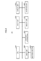
- FIG. 1 illustrates an example of a system configuration of an information processing system 1 according to a first embodiment of the present invention.
- the information processing system 1 includes physical servers 100 and 200 as examples of information processing apparatuses, physical switches 300 and 310, and a system visualization apparatus 400.
- a communication protocol is adopted, for example, Ethernet (trademark), IEEE 802.3, FDDI (Fiber-Distributed Data Interface), PPP (Point to Point Protocol), or the like.
- FIG. 2 illustrates an example of a hardware configuration of the physical server 100.
- the physical server 100 includes, for example, a CPU (Central Processing Unit) 100A, a drive unit 100B, an auxiliary storage unit 100D, a memory unit 100E, an interface unit 100F, an input unit 100G, and a display unit 100H. These elements are connected with each other via a bus, a serial communication channel, or the like.
- a CPU Central Processing Unit
- the CPU 100A is a processor that includes, for example, a program counter, an instruction decoder, various arithmetic units, an LSU (Load/Store Unit), and general-purpose registers.
- a program counter for example, a program counter, an instruction decoder, various arithmetic units, an LSU (Load/Store Unit), and general-purpose registers.
- an LSU Load/Store Unit
- the drive unit 100B is a unit that can read a program or data from a recording medium 100C.
- the recording medium 100C storing a program is mounted on the drive unit 100B, the program is installed from the recording medium 100C to the auxiliary storage unit 100D via the drive unit 100B.
- the recording medium 100C is a portable recording medium, for example, a CD-ROM, a DVD, a USB memory, or the like.
- the auxiliary storage unit 100D is, for example, an HDD (Hard Disk Drive) or a flash memory.
- Installation of a program can be executed not only by the recording medium 100C as above, but also by the interface unit 100F that downloads a program from another computer via a network and installs the program in the auxiliary storage unit 100D.
- the network may be the Internet, a LAN (Local Area Network), a wireless network, or the like.
- a program may be stored beforehand in the auxiliary storage unit 100D, a ROM (Read-Only Memory), or the like at shipment of the physical server 100.
- an information processing apparatus as illustrated in FIG. 1 can function as the physical server 100 according to the present embodiment.
- the memory unit 100E includes, for example, a RAM (Random Access Memory) and an EEPROM (Electrically Erasable and Programmable Read-Only Memory).
- the interface unit 100F controls connection with the network.
- the input unit 100G includes, for example, a keyboard, a mouse, a touch pad, a touch panel, and a microphone.
- the display unit 100H is a display device, for example, an LCD (Liquid Crystal Display), a CRT (Cathode Ray Tube), or the like.
- the physical server 100 may include other types of output units besides the display unit 100H, such as a printer and a loudspeaker.
- the physical server 200 can adopt the same hardware configuration as the physical server 100; hence its description is omitted.
- the physical server 100 is controlled by a host OS (Operating System) 110 and a guest OS 120 runs on the host OS 110. Also, the physical server 100 includes a NIC (Network Interface Card) 130 connected with a physical switch 300, and a NIC 132 connected with a physical switch 310.
- NIC Network Interface Card
- the physical server 100 includes software units build on the host OS 110 such as VIFs (Virtual Interfaces) 111 and 112, a bridge 113, and a mirror unit 114.
- VIFs Virtual Interfaces
- the physical server 100 includes software units build on the guest OS 120 such as VMs (Virtual Machines or Virtual Computers) 121 and 122.
- the VMs 121 and 122 include virtual NICs 123 and 124, respectively.
- the physical server 200 is controlled by a host OS (Operating System) 210 and a guest OS 220 runs on the host OS 210. Also, the physical server 200 includes a NIC (Network Interface Card) 230 connected with the physical switch 300, and a NIC 232 connected with the physical switch 310.
- a host OS Operating System
- a guest OS 220 runs on the host OS 210.
- the physical server 200 includes a NIC (Network Interface Card) 230 connected with the physical switch 300, and a NIC 232 connected with the physical switch 310.
- NIC Network Interface Card
- the physical server 200 includes software units build on the host OS 210 such as VIFs (Virtual Interfaces) 211 and 212, a bridge 213, and a mirror unit 214.
- VIFs Virtual Interfaces
- the physical server 200 includes software units build on the guest OS 220 such as VMs (Virtual Machines) 221 and 222.
- the VMs 221 and 222 include virtual NICs 223 and 224, respectively.
- the VMs 121, 122, 221, and 222 may have respective functions of, for example, a Web server, an application server, a database server, and the like, to provide various information services to client computers connected with the information processing system 1. Although it is assumed that two VMS exist on each of the physical servers in the present embodiment, any number of VMs may exist on each of the physical servers.
- FIG. 3 is a schematic view illustrating content of a MAC header MH and an IP header IH, which are header parts of a packet.
- the packet "A" is transferred to the physical switch 300 by the virtual NIC 123, the VIF 111, the bridge 113, and the NIC 130. Then, the packet "A” is transferred to the VM 221 by the physical switch 300, the NIC 230, the bridge 213, the VIF 211, and the virtual NIC 223.
- the destination of the packet is determined at the bridges 113 and 213, the physical switch 300, and the like, with reference to, for example, a destination MAC address that corresponds to the destination VIF.
- communication between VMs on the same physical server is executed via the bridge 113 by units of packets.
- the packet "B" is transferred by the virtual NIC 123, the VIF 111, the bridge 113, the VIF 112, and the virtual NIC 124.
- the physical switch 300 has a correspondence table (MAC address table, not illustrated) of MAC addresses and ports to transfer packets. Also, the physical switch 300 has a port mirroring function to transmit a copy of a transferred packet to the physical switch 310 (mirroring).
- MAC address table not illustrated
- port mirroring to transmit a copy of a transferred packet to the physical switch 310 (mirroring).
- the mirror unit 114 collects packets transmitted/received between VMs on the same physical server, and transmits the collected packets to the NIC 132.
- the NIC 132 transfers the packets input from the mirror unit 114 to the physical switch 310.
- the function of the mirror unit 214 is the same as that of the mirror unit 114.
- the mirrors units 114 and 214 use packet buffers 114A and 214A, respectively.
- the physical switch 310 transmits packets input from the physical switch 300 and the NICs 132 and 232 to the system visualization apparatus 400.
- packets transmitted/received between the physical servers or within the physical server are input to the system visualization apparatus 400, and data of all packets transmitted/received in the information processing system 1 are gathered in the system visualization apparatus 400.
- FIG. 4 illustrates an example of a configuration of the system visualization apparatus 400.
- the system visualization apparatus 400 includes a capture unit 410, a capture data storage unit 420, a message analysis unit 430, a protocol log storage unit 440, a log analysis unit 450, and a transaction data storage unit 460.
- the capture unit 410 receives a packet from the physical switch 310, and stores it in the capture data storage unit 420.
- the message analysis unit 430 extracts predetermined data from the packets stored in the capture data storage unit 420, and stores it in the protocol log storage unit 440.
- the log analysis unit 450 executes an analysis process of a log using the data stored in the protocol log storage unit 440, and stores it in the transaction data storage unit 460.
- the configuration of the system visualization apparatus 400 is just an example, and another configuration may be adopted.
- FIG. 5 is a schematic view conceptually illustrating an overview of the process executed by the mirror unit 114.
- the mirror unit 114 captures packets transmitted/received by all VMs in the physical server 100 (namely, packets that pass through the VIFs 111 and 112), and stores them in corresponding areas in the packet buffer 114A provided for each VM and each uplink/downlink distinction.
- the mirror unit 114 divides packets into uplink packets transmitted to the VM 121; downlink packets transmitted from the VM 121 to the other VM; uplink packets transmitted to the VM 122; and downlink packets transmitted from the VM 122 to the other VM, and stores them in the respective corresponding areas.
- uplink packets transmitted to the VM 121 are referred to as “VM 121 uplink packets”, and downlink packets transmitted from the VM 121 are referred to as “VM 121 downlink packets”.
- uplink packets transmitted to the VM 122 are referred to as “VM 122 uplink packets”, and downlink packets transmitted from the VM 122 are referred to as “VM 122 downlink packets”.
- an upward arrow attached to a packet that passes through the VIF 111 or 112 in FIG. 1 designates an uplink packet
- a downward arrow designates a downlink packet
- an uplink packet in the present embodiment may be defined as a packet that is transferred in a direction approaching a VM corresponding to the VIF at the position where the packet is captured (the VIF receives/transmits the packet).
- a downlink packet may be defined as a packet that is transferred in a direction moving away from the VM corresponding to a VIF at the position where the packet is captured.
- VMs may exist that correspond to a position where the packet is captured (an example is found in the second embodiment where a packet is captured at the NIC 130).
- the wording of "the corresponding VM” may be changed to "one of the corresponding VMs".
- VMs corresponding to the NIC 130 are all VMs (121 and 122) on the physical server 100
- VMs corresponding to the NIC 230 are all VMs (221 and 222) on the physical server 200.
- FIG. 6 is a flowchart of a process executed by the mirror unit 114 for determining whether a packet is an uplink packet or a downlink packet. This flowchart is executed every time a packet is captured.
- the mirror unit 114 compares the destination MAC address in the MAC header of a captured packet, with the MAC address of the VM corresponding to the VIF at the position where the packet is captured (Step S500). Then, the mirror unit 114 determines whether the destination MAC address and the MAC address of the VM are matched (Step S502).
- the mirror unit 114 determines that the packet is an uplink packet, and stores the packet in the corresponding area in the packet buffer 114A (Step S504).
- the mirror unit 114 compares the source MAC address in the MAC header of the packet, with the MAC address of the VM corresponding to the VIF at the position where the packet is captured (Step S506). Then, the mirror unit 114 determines whether the source MAC address and the MAC address of the VM are matched (Step S508).
- the mirror unit 114 determines that the packet is a downlink packet, and stores the packet in the corresponding area in the packet buffer 114A (Step S510).
- the mirror unit 114 determines that it is error data, and deletes the packet (Step S512).
- the process executed by the mirror unit 114 for determining whether it is an uplink packet or a downlink packet may be executed using the destination address and the source address included in the IP header of a packet.
- the mirror unit 114 holds table data in which IP addresses of the VMs correspond with the respective VIFs.
- FIG. 7 is another example of a flowchart of a process executed by the mirror unit 114 for determining whether a packet is an uplink packet or a downlink packet. This flowchart is executed every time a packet is captured.
- the mirror unit 114 compares the destination address in the IP header of a captured packet, with the IP address of the VM corresponding to the VIF at the position where the packet is captured (Step S600). Then, the mirror unit 114 determines whether the destination address and the IP address of the VM are matched (Step S602).
- the mirror unit 114 determines that the packet is an uplink packet, and stores the packet in the corresponding area in the packet buffer 114A (Step S604).
- the mirror unit 114 compares the source address in the IP header of the packet, with the IP address of the VM corresponding to the VIF at the position where the packet is captured (Step S606). Then, the mirror unit 114 determines whether the source address and the IP address of the VM are matched (Step S608).
- the mirror unit 114 determines that the packet is a downlink packet, and stores the packet in the corresponding area in the packet buffer 114A (Step S610).
- the mirror unit 114 determines that it is error data, and deletes the packet (Step S612).
- the mirror unit 114 After having stored the packet in the corresponding area in the packet buffer 114A by the process illustrated in FIG. 6 or 7 , the mirror unit 114 compares packets with each other to determine whether they are matched, and extracts packets that are transmitted/received between VMs on the same physical server 100 as illustrated in the lower part in FIG. 5 . Packet comparisons are executed for combinations of VM 121 uplink packets and VM 122 downlink packets, and combinations of VM 121 downlink packets and VM 122 uplink packets.
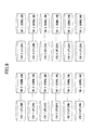
- FIG. 8 is a schematic view illustrating combinations of packet comparisons when the number of VMs is three.
- FIG. 9 is a schematic view illustrating combinations of packet comparisons when the number of VMs is four.
- VMs are denoted as VM 1, VM 2, and so on.
- the mirror unit 114 executes packet comparisons n ⁇ (n-1) times where n is the number of VMs.
- FIG. 10 is a flowchart of a process executed by the mirror unit 114 for packet comparison. This flowchart is repeatedly executed, for example, at predetermined intervals.
- the mirror unit 114 takes out a packet from the area where "VM 121 uplink packets" are stored in the packet buffer 114A (Step S700), and then, takes out a packet from the area where "VM 122 downlink packets" are stored (Step S702).
- the order of taking out packets may be determined based on, for example, FIFO (First In, First Out) basis.
- the mirror unit 114 compares the IDs, source addresses, and destination addresses of IP packets in the IP headers of the packets taken out at Steps S700 and S702, with which IP packets of the taken-out packets can be identified (Step S704). Then, the mirror unit 114 determines whether all of the IDs, source addresses, and destination addresses of the IP headers are matched (Step S706).
- the mirror unit 114 transmits one of the matched pair of packets (for example, a downlink packet) to the NIC 132 (Step S708). Then, the mirror unit 114 deletes the matched pair of packets in the packet buffer 114A (Step S710). After Step S710, the mirror unit 114 proceeds to Step S714, which will be described later.
- the mirror unit 114 determines whether all packets are taken out that are stored in the area for "VM 122 downlink packets" in a loop for "VM 122 downlink packets" (Step S712).
- the loop for "VM 122 downlink packets" is the loop where Steps S702-S710 are repeatedly executed. If not having taken out all of "VM 122 downlink packets" in the loop, the mirror unit 114 goes back to Step S702, takes out a next packet from "VM 122 downlink packets", and executes Steps S704 and after.
- Step S714 the mirror unit 114 determines whether all packets are taken out that are stored in the area for "VM 121 uplink packets" in a loop for "VM 121 uplink packets" (Step S714).
- the loop for "VM 121 uplink packets" is the loop where Steps S700-S712 are repeatedly executed. If not having taken out all of "VM 121 uplink packets" in the loop, the mirror unit 114 goes back to Step S700, takes out a next packet from "VM 121 uplink packets", and executes Steps S702 and after.
- the mirror unit 114 takes out a packet from the area where "VM 121 downlink packets" are stored in the packet buffer 114A (Step S720). Further, the mirror unit 114 takes out a packet from the area where "VM 122 uplink packets" are stored (Step S722).
- the mirror unit 114 compares the IDs, source addresses, and destination addresses of IP packets in the IP headers of the packets taken out Steps S720 and S722, with which IP packets of the taken-out packets can be identified (Step S724). Then, the mirror unit 114 determines whether all of the IDs, source addresses, and destination addresses of the IP headers are matched (Step S726).
- the mirror unit 114 transmits one of the matched pair of packets (for example, a downlink packet) to the NIC 132 (Step S728). Then, the mirror unit 114 deletes the matched pair of packets in the packet buffer 114A (Step S730).
- the mirror unit 114 determines whether all packets are taken out that are stored in the area for "VM 122 uplink packets" in a loop for "VM 122 uplink packets" (Step S732).
- the loop for "VM 122 uplink packets" is the loop where Steps S722-S730 are repeatedly executed. If not having taken out all of "VM 122 uplink packets" in the loop, the mirror unit 114 goes back to Step S722, takes out a next packet from "VM 122 uplink packets", and executes Steps S724 and after.
- Step S734 the mirror unit 114 determines whether all packets are taken out that are stored in the area for "VM 121 downlink packets" in a loop for "VM 121 downlink packets" (Step S734).
- the loop for "VM 121 downlink packets” is the loop where Steps S720-S732 are repeatedly executed. If not having taken out all of "VM 121 downlink packets" in the loop, the mirror unit 114 goes back to Step S720, takes out a next packet from "VM 121 downlink packets", and executes Steps S722 and after.
- the mirror unit 114 deletes packets that have a predetermined time passed since they have been captured among all packets in the packet buffer 114A (Step S740).
- the flowchart illustrated in FIG. 10 is for a case where the number of VMs existing on the physical server 100 is two. If the number of VMs existing on the physical server 100 is greater than two, the loops of Steps S700 to S714 and Steps S720-S734 may be executed n ⁇ (n-1) times.
- FIG. 11 is a schematic view illustrating a modified example of an information processing system 1# and physical servers 100# and 200#.
- elements that correspond to those in the information processing system 1 and the physical servers 100 and 200 in the first embodiment have the suffix of # in their numerical codes.
- a mirror unit 114# included in the physical server 100# in the modified example collects all packets that pass through VIFs 111# and 112#, and transmits them to a NIC 132#.
- data received/transmitted between multiple virtual machines on the same physical server can be output to an external device.
- the external device namely, a system visualization apparatus, can collect both data received/transmitted between multiple virtual machines on the same physical server, and data received/transmitted between the physical server and the external device.
- the information processing system and the physical servers in the first embodiment illustrated in FIG. 1 can reduce the load of packet transfer in the NIC 132 compared to the information processing system and the physical servers in the modified example. This is because the NIC 132# transfers "A ⁇ B ⁇ D ⁇ C ⁇ " in the physical server 100# in the modified example, whereas the NIC 132 transfers "B ⁇ D ⁇ " in the physical server 100 in the present embodiment.
- the information processing system and the physical servers in the first embodiment collect packets transmitted/received between VMs on the same physical server to transmit them to the NIC 132, but delegates mirroring of packets transmitted/received between different physical servers to the physical switch 300. Therefore, the load of packet transfer in the NIC 132 is not excessively high, which makes it possible to implement smooth information reception/transmission. Also, the physical servers do not need to be equipped with excessively highly-functional NICs 132 so that an increase of the cost and weight can be suppressed.
- the mirror unit 214 and the NIC 232 have the same relationship.
- Data received/transmitted between multiple virtual machines on the same the information processing apparatus can be output to an external device by using the physical server, the communication data output method and program, and the information processing system according to the present embodiment.
- the external device namely, a system visualization apparatus, can collect both data received/transmitted between multiple virtual machines on the same physical server, and data received/transmitted between the physical server and the external device.
- FIG. 12 illustrates an example of a system configuration of an information processing system 2 according to the second embodiment of the present invention.
- the information processing system 2 according to the second embodiment differs from that in the first embodiment in content of processing executed by the mirror unit. Therefore, the mirror unit is denoted as a mirror unit 114* or 214*, the packet buffer is denoted as a packet buffer 114*A or 214*A, and the other elements are assigned the same numeral codes as in the first embodiment.
- FIG. 13 is a schematic view conceptually illustrating an overview of the process executed by the mirror unit 114*.
- the mirror unit 114* captures packets transmitted/received by all VMs in the physical server 100 and packets that pass through the NIC 130, and stores them in corresponding areas in the packet buffer 114*A.
- the mirror unit 114* divides packets into downlink packets transmitted from the VM 121 to the other VM; downlink packets transmitted from the VM 122 to the other VM; and downlink packets transmitted from the NIC 130 to the physical switch 300, and stores them in the respective corresponding areas in the packet buffer 114*A.
- VM 121 downlink packets downlink packets transmitted from the VM 121 to the other VM
- VM 122 downlink packets downlink packets transmitted from the VM 122 to the other VM
- NIC 130 downlink packets the downlink packets transmitted from the NIC 130 to the physical switch 300 are referred to as "NIC 130 downlink packets”.
- uplink packets captured at the NIC 130 are packets received by the NIC 130 from an external device (the physical switch 300), and "downlink packets” are packets transmitted by NIC 130 to the external device (the physical switch 300).
- FIG. 14 is a flowchart of a process executed by the mirror unit 114* for selectively collecting downlink packets. This flowchart is executed every time a packet is captured by the mirror unit 114*.
- the mirror unit 114* determines whether it is a packet captured at the VIF 111 or the VIF 112 (Step S800).
- the mirror unit 114* executes the following steps.
- the mirror unit 114* compares the source MAC address in the MAC header of the captured packet, with the MAC address of the VM corresponding to the VIF at the position where the packet is captured (Step S802). Then, the mirror unit 114* determines whether the source MAC address and the MAC address of the VM are matched (Step S804).
- the mirror unit 114* determines that the packet is a downlink packet, and stores the packet in the corresponding area in the packet buffer 114*A (Step S806).
- the mirror unit 114* determines that the packet is an uplink packet or error data, and deletes the packet (Step S808).
- Step S800 determines whether it is a packet captured at the VIF 111 or the VIF 112, namely, it is a packet captured at the NIC 130. If it is determined at Step S800 that it is not a packet captured at the VIF 111 or the VIF 112, namely, it is a packet captured at the NIC 130, the mirror unit 114* executes the following steps.
- the mirror unit 114* compares the source MAC address with the MAC address of every VM (121 or 122) on the physical server 100 (Step S810). Then, the mirror unit 114* determines whether the source MAC address and one of the MAC addresses of the VMs are matched (Step S812).
- the mirror unit 114* determines that the packet is a downlink packet, and stores the packet in the corresponding area in the packet buffer 114*A (Step S814).
- the mirror unit 114* determines that the packet is an uplink packet or error data, and deletes the packet (Step S808).
- FIG. 15 is another example of a flowchart of a process executed by the mirror unit 114* for selectively collecting downlink packets. This flowchart is executed every time a packet is captured by the mirror unit 114*.
- the mirror unit 114* determines whether it is a packet captured at the VIF 111 or the VIF 112 (Step S900).
- the mirror unit 114* executes the following steps.
- the mirror unit 114* compares the source MAC address in the MAC header of the captured packet, with the IP address of the VM corresponding to the VIF at the position where the packet is captured (Step S902). Then, the mirror unit 114* determines whether the source MAC address and the IP address of the VM are matched (Step S904).
- the mirror unit 114* determines that the packet is a downlink packet, and stores the packet in the corresponding area in the packet buffer 114*A (Step S906).
- the mirror unit 114* determines that the packet is an uplink packet or error data, and deletes the packet (Step S908).
- Step S900 if it is determined at Step S900 that it is not a packet captured at the VIF 111 or the VIF 112, namely, it is a packet captured at the NIC 130, the mirror unit 114* executes the following steps.
- the mirror unit 114* compares the source address with the IP address of every VM (121 or 122) on the physical server 100 (Step S910). Then, the mirror unit 114* determines whether the source address and one of the IP addresses of the VMs are matched (Step S912).
- the mirror unit 114* determines that the packet is a downlink packet, and stores the packet in the corresponding area in the packet buffer 114*A (Step S914).
- the mirror unit 114* determines that the packet is an uplink packet or error data, and deletes the packet (Step S908) .
- the mirror unit 114* After having stored the packet in the corresponding area in the packet buffer 114*A, the mirror unit 114* compares packets with each other to determine whether they are matched, and extracts packets that are transmitted/received between VMs on the same physical server 100 as illustrated in the lower part in FIG. 13 . Packet comparisons are executed for combinations of VM 121 downlink packets and NIC 130 downlink packets, and combinations of VM 122 downlink packets and NIC 130 downlink packets, respectively.
- FIG. 16 is a flowchart of a process executed by the mirror unit 114* for packet comparison. The flow for example, predetermined time is repeatedly executed.
- the mirror unit 114* takes out a packet from the area where "VM 121 downlink packets" are stored in the packet buffer 114*A (Step S1000), and then, takes out a packet from the area where "NIC 130 downlink packets" are stored (Step S1002).
- the order of taking out packets may be determined based on, for example, FIFO (First In, First Out) basis.
- the mirror unit 114* compares the IDs, source addresses, and destination addresses of IP packets in the IP headers of the packets taken out at Steps S1000 and S1002, with which IP packets of the taken-out packets can be identified (Step S1004). Then, the mirror unit 114* determines whether all of the IDs, source addresses, and destination addresses of the IP headers are matched (Step 1006).
- Step 1008 the mirror unit 114* deletes the matched pair of packets in the packet buffer 114*A (Step 1008). After Step S1008, the mirror unit 114* proceeds to Step S1012, which will be described later.
- the mirror unit 114* determines whether all packets are taken out that are stored in the area for "NIC 130 downlink packets" in a loop for "NIC 130 downlink packets" (Step S1010).
- the loop for "NIC 130 downlink packets" is the loop where Steps S1002-S1008 are repeatedly executed. If not having taken out all of "NIC 130 downlink packets" in the loop, the mirror unit 114* goes back to Step S1002, takes out a next packet from "NIC 130 downlink packets", and executes Steps S1004 and after.
- the mirror unit 114* executes the following steps.
- the mirror unit 114* determines whether all packets are taken out that are stored in the area for "VM 121 downlink packets" in a loop for "VM 121 downlink packets" (Step S1012).
- the loop for "VM 121 downlink packets" is the loop where Steps S1000-S1010 are repeatedly executed. If not having taken out all of "VM 121 downlink packets" in the loop, the mirror unit 114* goes back to Step S1000, takes out a next packet from "VM 121 downlink packets", and executes Steps S1002 and after.
- the mirror unit 114* takes out a packet from the area where "VM 122 downlink packets" are stored in the packet buffer 114*A (Step S1020). Next, the mirror unit 114* takes out a packet from the area where "NIC 130 downlink packets" are stored (Step S1022).
- the mirror unit 114* compares the IDs, source addresses, and destination addresses of IP packets in the IP headers of the packets taken out Steps 1020 and S1022, with which IP packets of the taken-out packets can be identified (Step S1024). Then, the mirror unit 114* determines whether all of the IDs, source addresses, and destination addresses of the IP headers are matched (Step S1026).
- Step S1028 the mirror unit 114* deletes the matched pair of packets in the packet buffer 114*A. After Step S1028, the mirror unit 114* proceeds to Step S1032, which will be described later.
- the mirror unit 114* determines whether all packets are taken out that are stored in the area for "NIC 130 downlink packets" in a loop for "NIC 130 downlink packets" (Step S1030).
- the loop for "NIC 130 downlink packets" is the loop where Steps S1022-S1028 are repeatedly executed. If not having taken out all of "NIC 130 downlink packets" in the loop, the mirror unit 114* goes back to Step S1022, takes out a next packet from "NIC 130 downlink packets", and executes Steps S1024 and after.
- the mirror unit 114* executes the following steps.
- the mirror unit 114* determines whether all packets are taken out that are stored in the area for "VM 122 downlink packets" in a loop for "VM 122 downlink packets" (Step S1032).
- the loop for "VM 122 downlink packets" is the loop where Steps S1020-S1030 are repeatedly executed. If not having taken out all of "VM 122 downlink packets" in the loop, the mirror unit 114* goes back to Step S1020, takes out a next packet from "VM 122 downlink packets", and executes Steps S1022 and after.
- the mirror unit 114* transmits packets that have a predetermined time passed since they have been captured among all packets in the packet buffer 114*A, to the NIC 132 (Step S1040).
- Steps S1000-S1012 and Steps S1020-S1032 may be executed n ⁇ (n-1) times.
- Data received/transmitted between multiple virtual machines on the same the information processing apparatus can be output to an external device by using the physical server, the communication data output method and program, and the information processing system according to the present embodiment.
- the external device namely, a system visualization apparatus, can collect both data received/transmitted between multiple virtual machines on the same physical server, and data received/transmitted between the physical server and the external device.
- the number of areas to store captured packets in the packet buffer 114*A can be decreased (see FIGs. 5 and 13 ).
- FIG. 17 illustrates an example of a system configuration of an information processing system 3 according to the third embodiment of the present invention.
- host OSes 110 and 210 of physical servers 100 and 200 include MAC address tables 115 and 125, respectively.
- the MAC address table 115 is table data set in the auxiliary storage unit 100D or the memory unit 100E.
- the MAC address table 215 is table data set in the auxiliary storage unit 200D or the memory unit 200E.
- the information processing system 3 according to the third embodiment differs from that in the first embodiment in content of processing executed by the bridge and the mirror unit. Therefore, they is denoted as a bridge 113** or 213**, and a mirror unit 114** or 214**, and the other elements are assigned the same numeral codes as in the first embodiment.
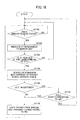
- FIG. 18 is a flowchart of a process executed by the bridge 113** and the mirror unit 114**, or by the bridge 213** and the mirror unit 214** according to the third embodiment. Although a process will be described with the bridge 113** and the mirror unit 114** in the following, the process is similarly executed with the bridge 213** and the mirror unit 214**.
- the bridge 113** waits for receiving a packet from the VIF 111 or 112, or the NIC 130 (Step S1100).
- the bridge 113** indicates it to the mirror unit 114** (Step S1102).
- the mirror unit 114** determines whether the packet is received at a virtual port of the bridge 113** corresponding to the VIF 111 or 112 (Step S1104).
- the mirror unit 114** goes back to S1100, and waits until the bridge 113** receives a packet.
- the mirror unit 114** searches for the destination MAC address of the packet in the MAC address table 115 (Step S1106).
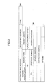
- FIG. 19 is a schematic view illustrating an example of data stored as the MAC address table 115.
- the MAC address table 115 stores MAC addresses learned by the bridge 113** (learned MAC header addresses) associated with respective virtual ports.
- the mirror unit 114** determines whether the destination MAC address of the packet is registered in the MAC address table 115 (Step S1108).
- the mirror unit 114** copies the packet from the bridge 113**, and transmits the copied packet to the NIC 132 (Step S1110).
- the bridge 113** has a function to register the source MAC address of the received packet in the MAC address table 115 to be associated with the virtual port where the packet is received.
- the mirror unit 114** determines whether the port corresponding to the destination MAC address in the MAC address table 115 is a port corresponding to the VIF 111 or 112 (Step S1112).
- the mirror unit 114** goes back to S1100, and waits until the bridge 113** receives a packet.
- the mirror unit 114** copies the packet from the bridge 113**, and transmits the copied packet to the NIC 132 (Step S1110).
- the packet A in FIG. 17 is transmitted from the VM 121 to the VM 221.
- the packet A is not transmitted to the NIC 132 because the port corresponds to the NIC 130.
- the packet A is transmitted to the NIC 132.
- mirroring is also executed at the physical switch 300 for the packet A, and the packet A is transmitted to the system visualization apparatus 400 with duplication; such duplication is within a tolerable range because it is registered in the MAC address table 115 thereafter.
- the packet C is transmitted from the VM 221 to the VM 121, the packet C is not transmitted to the NIC 132 because it is received at the port corresponds to the NIC 130 in the bridge 113**.
- Data received/transmitted between multiple virtual machines on the same information processing apparatus can be output to an external device by using the physical server, the communication data output method and program, and the information processing system according to the present embodiment.
- the external device namely, a system visualization apparatus, can collect both data received/transmitted between multiple virtual machines on the same physical server, and data received/transmitted between the physical server and the external device.
- the information processing apparatus in the third embodiment may collect packets using IP addresses instead of MAC addresses, similarly to the first embodiment.
- the mirror unit 114* in the second embodiment captures downlink packets received/transmitted by all VMs and downlink packets passing through the NIC 130, and excludes those having equivalent contents, but it is not limited to that.
- the mirror unit 114* in the second embodiment may capture uplink packets received/transmitted by all VMs and uplink packets passing through the NIC 130, and excludes those having equivalent contents to transmit remaining packets to the NIC 132.
- the physical switches 300 and 310 may be integrated into a single physical switch.
- OSes or VMs may be arbitrarily placed within the system in the respective embodiments, to which the present invention can be applied as long as multiple VMs exist on an information processing apparatus (physical server).
- the physical server has two NICs, one for receiving/transmitting packets with an external device, and the other for transmitting packets collected by the mirror unit, but the same NIC may cover both packets exchanged with an external device, and packets collected by the mirror unit.
- the present invention can be used in the computer manufacturing industry, computer software industry, information service provider industry, and the like.
Landscapes
- Engineering & Computer Science (AREA)
- Computer Networks & Wireless Communication (AREA)
- Signal Processing (AREA)
- Software Systems (AREA)
- Theoretical Computer Science (AREA)
- Data Mining & Analysis (AREA)
- Physics & Mathematics (AREA)
- General Engineering & Computer Science (AREA)
- General Physics & Mathematics (AREA)
- Data Exchanges In Wide-Area Networks (AREA)
Applications Claiming Priority (1)
| Application Number | Priority Date | Filing Date | Title |
|---|---|---|---|
| PCT/JP2012/051880 WO2013111343A1 (fr) | 2012-01-27 | 2012-01-27 | Dispositif de traitement d'informations, système de traitement d'informations, procédé de délivrance de données de communication et programme de délivrance de données de communication |
Publications (2)
| Publication Number | Publication Date |
|---|---|
| EP2809035A1 true EP2809035A1 (fr) | 2014-12-03 |
| EP2809035A4 EP2809035A4 (fr) | 2015-06-03 |
Family
ID=48873104
Family Applications (1)
| Application Number | Title | Priority Date | Filing Date |
|---|---|---|---|
| EP12866923.1A Withdrawn EP2809035A4 (fr) | 2012-01-27 | 2012-01-27 | Dispositif de traitement d'informations, système de traitement d'informations, procédé de délivrance de données de communication et programme de délivrance de données de communication |
Country Status (4)
| Country | Link |
|---|---|
| US (1) | US9703580B2 (fr) |
| EP (1) | EP2809035A4 (fr) |
| JP (1) | JP5825360B2 (fr) |
| WO (1) | WO2013111343A1 (fr) |
Families Citing this family (6)
| Publication number | Priority date | Publication date | Assignee | Title |
|---|---|---|---|---|
| JP6041636B2 (ja) * | 2012-11-26 | 2016-12-14 | キヤノン株式会社 | 情報処理装置、情報処理装置の制御方法、及びプログラム |
| US9262090B2 (en) * | 2013-02-26 | 2016-02-16 | Lenovo Enterprise Solutions (Singapore) Pte. Ltd. | Asynchronous data mirroring in memory controller |
| KR102209525B1 (ko) * | 2014-01-06 | 2021-01-29 | 삼성전자주식회사 | 마이크로 서버, mac 주소 할당 방법 및 컴퓨터 판독가능 기록매체 |
| JP6248763B2 (ja) * | 2014-03-31 | 2017-12-20 | 富士通株式会社 | キャプチャポイント決定方法、キャプチャポイント決定システムおよびキャプチャポイント決定プログラム |
| WO2018179413A1 (fr) * | 2017-03-31 | 2018-10-04 | 三菱電機株式会社 | Dispositif de traitement d'informations et procédé de traitement d'informations |
| JP7003562B2 (ja) * | 2017-10-16 | 2022-01-20 | 富士通株式会社 | ミラーパケット制御プログラム、ミラーパケット制御方法、およびミラーパケット制御装置 |
Family Cites Families (18)
| Publication number | Priority date | Publication date | Assignee | Title |
|---|---|---|---|---|
| US6041042A (en) * | 1997-05-27 | 2000-03-21 | Cabletron Systems, Inc. | Remote port mirroring system and method thereof |
| US7782784B2 (en) * | 2003-01-10 | 2010-08-24 | Cisco Technology, Inc. | Port analyzer adapter |
| US7626938B1 (en) * | 2005-03-31 | 2009-12-01 | Marvell Israel (M.I.S.L) Ltd. | Local area network switch using control plane packet mirroring to support multiple network traffic analysis devices |
| JP4570527B2 (ja) * | 2005-07-20 | 2010-10-27 | 富士通株式会社 | システム性能監視プログラム及びシステム性能監視方法 |
| US8050185B2 (en) * | 2005-08-24 | 2011-11-01 | Hewlett-Packard Development Company, L.P. | Sampling of network traffic based on CAM lookup |
| US8397284B2 (en) * | 2006-01-17 | 2013-03-12 | University Of Maryland | Detection of distributed denial of service attacks in autonomous system domains |
| US20070266433A1 (en) * | 2006-03-03 | 2007-11-15 | Hezi Moore | System and Method for Securing Information in a Virtual Computing Environment |
| JP5217886B2 (ja) * | 2008-10-14 | 2013-06-19 | 富士通株式会社 | ループバック装置及びミラーリング方法 |
| EP2401683A4 (fr) * | 2009-02-27 | 2015-07-29 | Broadcom Corp | Procédé et système de réseautage de machines virtuelles |
| US8265075B2 (en) * | 2009-03-16 | 2012-09-11 | International Business Machines Corporation | Method and apparatus for managing, configuring, and controlling an I/O virtualization device through a network switch |
| US9063769B2 (en) * | 2010-02-04 | 2015-06-23 | Telefonaktiebolaget Lm Ericsson (Publ) | Network performance monitor for virtual machines |
| JP5630033B2 (ja) | 2010-03-02 | 2014-11-26 | 富士通株式会社 | バッファ管理プログラム及び方法、並びにメッセージ分析装置 |
| JP5560936B2 (ja) * | 2010-06-16 | 2014-07-30 | 富士通株式会社 | 構成情報取得方法、仮想プローブおよび構成情報取得制御装置 |
| US8520540B1 (en) * | 2010-07-30 | 2013-08-27 | Cisco Technology, Inc. | Remote traffic monitoring through a network |
| JP5556507B2 (ja) * | 2010-08-30 | 2014-07-23 | 富士通株式会社 | 仮想マシン管理プログラム、仮想マシン管理方法、および仮想マシン管理装置 |
| US9191327B2 (en) * | 2011-02-10 | 2015-11-17 | Varmour Networks, Inc. | Distributed service processing of network gateways using virtual machines |
| US9110703B2 (en) * | 2011-06-07 | 2015-08-18 | Hewlett-Packard Development Company, L.P. | Virtual machine packet processing |
| WO2014000297A1 (fr) * | 2012-06-30 | 2014-01-03 | 华为技术有限公司 | Procédé et dispositif de surveillance de port virtuel |
-
2012
- 2012-01-27 EP EP12866923.1A patent/EP2809035A4/fr not_active Withdrawn
- 2012-01-27 JP JP2013555095A patent/JP5825360B2/ja active Active
- 2012-01-27 WO PCT/JP2012/051880 patent/WO2013111343A1/fr active Application Filing
-
2014
- 2014-07-03 US US14/322,979 patent/US9703580B2/en active Active
Also Published As
| Publication number | Publication date |
|---|---|
| US20140317623A1 (en) | 2014-10-23 |
| JPWO2013111343A1 (ja) | 2015-05-11 |
| JP5825360B2 (ja) | 2015-12-02 |
| WO2013111343A1 (fr) | 2013-08-01 |
| EP2809035A4 (fr) | 2015-06-03 |
| US9703580B2 (en) | 2017-07-11 |
Similar Documents
| Publication | Publication Date | Title |
|---|---|---|
| EP2809035A1 (fr) | Dispositif de traitement d'informations, système de traitement d'informations, procédé de délivrance de données de communication et programme de délivrance de données de communication | |
| US11902124B2 (en) | Round trip time (RTT) measurement based upon sequence number | |
| US11379443B2 (en) | Detecting outliers in server transaction time as a form of time series data | |
| CN106489251B (zh) | 应用拓扑关系发现的方法、装置和系统 | |
| US8086739B2 (en) | Method and system for monitoring virtual wires | |
| EP3028417B1 (fr) | Traitement de paquets de données | |
| EP2631796A1 (fr) | Procédé de collecte de données et système de traitement dýinformations | |
| US10164822B2 (en) | Flatnet failover control | |
| Yang et al. | Implementation of a real-time network traffic monitoring service with network functions virtualization | |
| JP2014048900A (ja) | 計算機システム及びパケット転送方法 | |
| US10397353B2 (en) | Context enriched distributed logging services for workloads in a datacenter | |
| CN106357726B (zh) | 负载均衡方法及装置 | |
| JP2011154489A (ja) | システム可視化プログラム、方法及び装置 | |
| WO2020242474A1 (fr) | Routage de paquets nvme over fabrics | |
| CN114172854A (zh) | 报文镜像、镜像配置方法、虚拟交换机及镜像配置装置 | |
| KR20220037444A (ko) | 성능 라우팅 측정치들을 이용한 양방향 포워딩 검출을 제공하기 위한 시스템들 및 방법들 | |
| JP6021436B2 (ja) | 画面被操作装置、画面被操作方法及び画面被操作プログラム | |
| JP7082884B2 (ja) | 通信装置、通信システム、及び通信方法 | |
| KR101707073B1 (ko) | Sdn 기반의 에러 탐색 네트워크 시스템 | |
| TWI534623B (zh) | 在單機中實現多人操作的控制系統與方法 | |
| JP6496860B2 (ja) | 監視システム、監視方法および監視プログラム | |
| JP6317833B1 (ja) | 監視システム、監視方法、情報処理装置および監視プログラム | |
| Fu et al. | FlowLever: Leverage Flow Director for Packet Dispatch Acceleration in NFV | |
| CN116909831A (zh) | 用于规则推荐的机器学习 | |
| CN116915643A (zh) | 用于规则评估的机器学习 |
Legal Events
| Date | Code | Title | Description |
|---|---|---|---|
| PUAI | Public reference made under article 153(3) epc to a published international application that has entered the european phase |
Free format text: ORIGINAL CODE: 0009012 |
|
| 17P | Request for examination filed |
Effective date: 20140703 |
|
| AK | Designated contracting states |
Kind code of ref document: A1 Designated state(s): AL AT BE BG CH CY CZ DE DK EE ES FI FR GB GR HR HU IE IS IT LI LT LU LV MC MK MT NL NO PL PT RO RS SE SI SK SM TR |
|
| DAX | Request for extension of the european patent (deleted) | ||
| RA4 | Supplementary search report drawn up and despatched (corrected) |
Effective date: 20150507 |
|
| RIC1 | Information provided on ipc code assigned before grant |
Ipc: H04L 12/26 20060101ALI20150429BHEP Ipc: H04L 12/70 20130101AFI20150429BHEP |
|
| STAA | Information on the status of an ep patent application or granted ep patent |
Free format text: STATUS: THE APPLICATION HAS BEEN WITHDRAWN |
|
| 18W | Application withdrawn |
Effective date: 20171218 |