WO2013108733A1 - Epitaxial wafer for heterojunction field-effect transistor - Google Patents
Epitaxial wafer for heterojunction field-effect transistor Download PDFInfo
- Publication number
- WO2013108733A1 WO2013108733A1 PCT/JP2013/050519 JP2013050519W WO2013108733A1 WO 2013108733 A1 WO2013108733 A1 WO 2013108733A1 JP 2013050519 W JP2013050519 W JP 2013050519W WO 2013108733 A1 WO2013108733 A1 WO 2013108733A1
- Authority
- WO
- WIPO (PCT)
- Prior art keywords
- layer
- superlattice
- buffer layer
- layer structure
- composition
- Prior art date
Links
- 230000005669 field effect Effects 0.000 title claims abstract description 5
- 239000000872 buffer Substances 0.000 claims abstract description 70
- 239000000758 substrate Substances 0.000 claims abstract description 32
- 239000004065 semiconductor Substances 0.000 claims abstract description 23
- 150000004767 nitrides Chemical class 0.000 claims abstract description 19
- 229910002704 AlGaN Inorganic materials 0.000 claims abstract description 12
- 239000000470 constituent Substances 0.000 claims description 27
- 229910016920 AlzGa1−z Inorganic materials 0.000 abstract 1
- 230000007423 decrease Effects 0.000 abstract 1
- 235000012431 wafers Nutrition 0.000 description 45
- 230000000052 comparative effect Effects 0.000 description 14
- JLTRXTDYQLMHGR-UHFFFAOYSA-N trimethylaluminium Chemical compound C[Al](C)C JLTRXTDYQLMHGR-UHFFFAOYSA-N 0.000 description 11
- XCZXGTMEAKBVPV-UHFFFAOYSA-N trimethylgallium Chemical compound C[Ga](C)C XCZXGTMEAKBVPV-UHFFFAOYSA-N 0.000 description 10
- 230000004888 barrier function Effects 0.000 description 6
- 230000015572 biosynthetic process Effects 0.000 description 6
- 239000013078 crystal Substances 0.000 description 5
- 238000004519 manufacturing process Methods 0.000 description 5
- 239000012495 reaction gas Substances 0.000 description 4
- 238000005136 cathodoluminescence Methods 0.000 description 3
- OKTJSMMVPCPJKN-UHFFFAOYSA-N Carbon Chemical compound [C] OKTJSMMVPCPJKN-UHFFFAOYSA-N 0.000 description 2
- KRHYYFGTRYWZRS-UHFFFAOYSA-N Fluorane Chemical compound F KRHYYFGTRYWZRS-UHFFFAOYSA-N 0.000 description 2
- XUIMIQQOPSSXEZ-UHFFFAOYSA-N Silicon Chemical compound [Si] XUIMIQQOPSSXEZ-UHFFFAOYSA-N 0.000 description 2
- QGZKDVFQNNGYKY-UHFFFAOYSA-N ammonia Natural products N QGZKDVFQNNGYKY-UHFFFAOYSA-N 0.000 description 2
- 229910052799 carbon Inorganic materials 0.000 description 2
- 238000000034 method Methods 0.000 description 2
- 229910000069 nitrogen hydride Inorganic materials 0.000 description 2
- 229910052710 silicon Inorganic materials 0.000 description 2
- 239000010703 silicon Substances 0.000 description 2
- UFHFLCQGNIYNRP-UHFFFAOYSA-N Hydrogen Chemical compound [H][H] UFHFLCQGNIYNRP-UHFFFAOYSA-N 0.000 description 1
- 238000002441 X-ray diffraction Methods 0.000 description 1
- XKMRRTOUMJRJIA-UHFFFAOYSA-N ammonia nh3 Chemical compound N.N XKMRRTOUMJRJIA-UHFFFAOYSA-N 0.000 description 1
- 238000001816 cooling Methods 0.000 description 1
- 230000003247 decreasing effect Effects 0.000 description 1
- 230000001419 dependent effect Effects 0.000 description 1
- 238000005530 etching Methods 0.000 description 1
- 238000011156 evaluation Methods 0.000 description 1
- 239000007789 gas Substances 0.000 description 1
- 229910052739 hydrogen Inorganic materials 0.000 description 1
- 239000001257 hydrogen Substances 0.000 description 1
- 238000002955 isolation Methods 0.000 description 1
- 239000002184 metal Substances 0.000 description 1
- 238000005121 nitriding Methods 0.000 description 1
- 238000000206 photolithography Methods 0.000 description 1
- 229910052594 sapphire Inorganic materials 0.000 description 1
- 239000010980 sapphire Substances 0.000 description 1
- 230000005533 two-dimensional electron gas Effects 0.000 description 1
- 238000007740 vapor deposition Methods 0.000 description 1
Images


Classifications
-
- H—ELECTRICITY
- H01—ELECTRIC ELEMENTS
- H01L—SEMICONDUCTOR DEVICES NOT COVERED BY CLASS H10
- H01L29/00—Semiconductor devices adapted for rectifying, amplifying, oscillating or switching, or capacitors or resistors with at least one potential-jump barrier or surface barrier, e.g. PN junction depletion layer or carrier concentration layer; Details of semiconductor bodies or of electrodes thereof ; Multistep manufacturing processes therefor
- H01L29/02—Semiconductor bodies ; Multistep manufacturing processes therefor
- H01L29/12—Semiconductor bodies ; Multistep manufacturing processes therefor characterised by the materials of which they are formed
- H01L29/15—Structures with periodic or quasi periodic potential variation, e.g. multiple quantum wells, superlattices
- H01L29/151—Compositional structures
- H01L29/152—Compositional structures with quantum effects only in vertical direction, i.e. layered structures with quantum effects solely resulting from vertical potential variation
-
- H—ELECTRICITY
- H01—ELECTRIC ELEMENTS
- H01L—SEMICONDUCTOR DEVICES NOT COVERED BY CLASS H10
- H01L21/00—Processes or apparatus adapted for the manufacture or treatment of semiconductor or solid state devices or of parts thereof
- H01L21/02—Manufacture or treatment of semiconductor devices or of parts thereof
- H01L21/02104—Forming layers
- H01L21/02365—Forming inorganic semiconducting materials on a substrate
- H01L21/02367—Substrates
- H01L21/0237—Materials
- H01L21/02373—Group 14 semiconducting materials
- H01L21/02381—Silicon, silicon germanium, germanium
-
- H—ELECTRICITY
- H01—ELECTRIC ELEMENTS
- H01L—SEMICONDUCTOR DEVICES NOT COVERED BY CLASS H10
- H01L21/00—Processes or apparatus adapted for the manufacture or treatment of semiconductor or solid state devices or of parts thereof
- H01L21/02—Manufacture or treatment of semiconductor devices or of parts thereof
- H01L21/02104—Forming layers
- H01L21/02365—Forming inorganic semiconducting materials on a substrate
- H01L21/02436—Intermediate layers between substrates and deposited layers
- H01L21/02439—Materials
- H01L21/02455—Group 13/15 materials
- H01L21/02458—Nitrides
-
- H—ELECTRICITY
- H01—ELECTRIC ELEMENTS
- H01L—SEMICONDUCTOR DEVICES NOT COVERED BY CLASS H10
- H01L21/00—Processes or apparatus adapted for the manufacture or treatment of semiconductor or solid state devices or of parts thereof
- H01L21/02—Manufacture or treatment of semiconductor devices or of parts thereof
- H01L21/02104—Forming layers
- H01L21/02365—Forming inorganic semiconducting materials on a substrate
- H01L21/02436—Intermediate layers between substrates and deposited layers
- H01L21/02494—Structure
- H01L21/02496—Layer structure
- H01L21/02505—Layer structure consisting of more than two layers
- H01L21/02507—Alternating layers, e.g. superlattice
-
- H—ELECTRICITY
- H01—ELECTRIC ELEMENTS
- H01L—SEMICONDUCTOR DEVICES NOT COVERED BY CLASS H10
- H01L21/00—Processes or apparatus adapted for the manufacture or treatment of semiconductor or solid state devices or of parts thereof
- H01L21/02—Manufacture or treatment of semiconductor devices or of parts thereof
- H01L21/02104—Forming layers
- H01L21/02365—Forming inorganic semiconducting materials on a substrate
- H01L21/02518—Deposited layers
- H01L21/02521—Materials
- H01L21/02538—Group 13/15 materials
- H01L21/0254—Nitrides
-
- H—ELECTRICITY
- H01—ELECTRIC ELEMENTS
- H01L—SEMICONDUCTOR DEVICES NOT COVERED BY CLASS H10
- H01L21/00—Processes or apparatus adapted for the manufacture or treatment of semiconductor or solid state devices or of parts thereof
- H01L21/02—Manufacture or treatment of semiconductor devices or of parts thereof
- H01L21/02104—Forming layers
- H01L21/02365—Forming inorganic semiconducting materials on a substrate
- H01L21/02612—Formation types
- H01L21/02617—Deposition types
- H01L21/0262—Reduction or decomposition of gaseous compounds, e.g. CVD
-
- H—ELECTRICITY
- H01—ELECTRIC ELEMENTS
- H01L—SEMICONDUCTOR DEVICES NOT COVERED BY CLASS H10
- H01L29/00—Semiconductor devices adapted for rectifying, amplifying, oscillating or switching, or capacitors or resistors with at least one potential-jump barrier or surface barrier, e.g. PN junction depletion layer or carrier concentration layer; Details of semiconductor bodies or of electrodes thereof ; Multistep manufacturing processes therefor
- H01L29/02—Semiconductor bodies ; Multistep manufacturing processes therefor
- H01L29/12—Semiconductor bodies ; Multistep manufacturing processes therefor characterised by the materials of which they are formed
- H01L29/15—Structures with periodic or quasi periodic potential variation, e.g. multiple quantum wells, superlattices
- H01L29/151—Compositional structures
- H01L29/152—Compositional structures with quantum effects only in vertical direction, i.e. layered structures with quantum effects solely resulting from vertical potential variation
- H01L29/155—Comprising only semiconductor materials
-
- H—ELECTRICITY
- H01—ELECTRIC ELEMENTS
- H01L—SEMICONDUCTOR DEVICES NOT COVERED BY CLASS H10
- H01L29/00—Semiconductor devices adapted for rectifying, amplifying, oscillating or switching, or capacitors or resistors with at least one potential-jump barrier or surface barrier, e.g. PN junction depletion layer or carrier concentration layer; Details of semiconductor bodies or of electrodes thereof ; Multistep manufacturing processes therefor
- H01L29/02—Semiconductor bodies ; Multistep manufacturing processes therefor
- H01L29/12—Semiconductor bodies ; Multistep manufacturing processes therefor characterised by the materials of which they are formed
- H01L29/20—Semiconductor bodies ; Multistep manufacturing processes therefor characterised by the materials of which they are formed including, apart from doping materials or other impurities, only AIIIBV compounds
- H01L29/2003—Nitride compounds
-
- H—ELECTRICITY
- H01—ELECTRIC ELEMENTS
- H01L—SEMICONDUCTOR DEVICES NOT COVERED BY CLASS H10
- H01L29/00—Semiconductor devices adapted for rectifying, amplifying, oscillating or switching, or capacitors or resistors with at least one potential-jump barrier or surface barrier, e.g. PN junction depletion layer or carrier concentration layer; Details of semiconductor bodies or of electrodes thereof ; Multistep manufacturing processes therefor
- H01L29/02—Semiconductor bodies ; Multistep manufacturing processes therefor
- H01L29/12—Semiconductor bodies ; Multistep manufacturing processes therefor characterised by the materials of which they are formed
- H01L29/20—Semiconductor bodies ; Multistep manufacturing processes therefor characterised by the materials of which they are formed including, apart from doping materials or other impurities, only AIIIBV compounds
- H01L29/201—Semiconductor bodies ; Multistep manufacturing processes therefor characterised by the materials of which they are formed including, apart from doping materials or other impurities, only AIIIBV compounds including two or more compounds, e.g. alloys
- H01L29/205—Semiconductor bodies ; Multistep manufacturing processes therefor characterised by the materials of which they are formed including, apart from doping materials or other impurities, only AIIIBV compounds including two or more compounds, e.g. alloys in different semiconductor regions, e.g. heterojunctions
-
- H—ELECTRICITY
- H01—ELECTRIC ELEMENTS
- H01L—SEMICONDUCTOR DEVICES NOT COVERED BY CLASS H10
- H01L29/00—Semiconductor devices adapted for rectifying, amplifying, oscillating or switching, or capacitors or resistors with at least one potential-jump barrier or surface barrier, e.g. PN junction depletion layer or carrier concentration layer; Details of semiconductor bodies or of electrodes thereof ; Multistep manufacturing processes therefor
- H01L29/66—Types of semiconductor device ; Multistep manufacturing processes therefor
- H01L29/68—Types of semiconductor device ; Multistep manufacturing processes therefor controllable by only the electric current supplied, or only the electric potential applied, to an electrode which does not carry the current to be rectified, amplified or switched
- H01L29/76—Unipolar devices, e.g. field effect transistors
- H01L29/772—Field effect transistors
- H01L29/778—Field effect transistors with two-dimensional charge carrier gas channel, e.g. HEMT ; with two-dimensional charge-carrier layer formed at a heterojunction interface
- H01L29/7786—Field effect transistors with two-dimensional charge carrier gas channel, e.g. HEMT ; with two-dimensional charge-carrier layer formed at a heterojunction interface with direct single heterostructure, i.e. with wide bandgap layer formed on top of active layer, e.g. direct single heterostructure MIS-like HEMT
- H01L29/7787—Field effect transistors with two-dimensional charge carrier gas channel, e.g. HEMT ; with two-dimensional charge-carrier layer formed at a heterojunction interface with direct single heterostructure, i.e. with wide bandgap layer formed on top of active layer, e.g. direct single heterostructure MIS-like HEMT with wide bandgap charge-carrier supplying layer, e.g. direct single heterostructure MODFET
Definitions
- the present invention relates to an epitaxial wafer for producing a heterojunction field effect transistor including a plurality of nitride-based semiconductor layers capable of generating a two-dimensional electron gas (2DEG), and particularly to reduction of warpage and dislocation density in the wafer.
- 2DEG two-dimensional electron gas
- GaN substrates are expensive, and epitaxial crystal growth of those layers on sapphire substrates and Si substrates has been conventionally performed. ing.
- AlxGa1-xN (0.5) is formed on a silicon substrate for the purpose of forming a nitride semiconductor layer having a smooth surface and containing no cracks on a substrate having greatly different lattice constants and thermal expansion coefficients.
- ⁇ x ⁇ 1) first superlattice constituent layers and AlyGa1-yN (0.01 ⁇ y ⁇ 0.2) second superlattice constituent layers are alternately and repeatedly stacked to form an AlGaN superlattice buffer layer structure. It is described to form.
- Patent Document 2 in order to suppress current leakage between electrodes through the buffer layer, an AlN buffer layer on a silicon substrate and a high Al composition ratio H—AlGaN superlayer alternately stacked thereon are formed.
- a semiconductor device having a lattice structure layer and a superlattice buffer layer structure including an L-AlGaN superlattice structure layer having a low Al composition ratio is described.
- a composition gradient buffer layer structure in which the Al composition ratio is continuously or stepwise decreased in the thickness direction is formed on an Si substrate or an intermediate layer formed on the Si substrate.
- a superlattice buffer layer structure including AlGaN superlattice constituent layers with high Al composition ratios and AlGaN superlattice constituent layers with low Al composition ratios, which are alternately stacked, is formed, and a nitride layer serving as a channel layer is formed thereon. ing. It is stated that by using such a laminated structure, a semiconductor element having a nitride semiconductor layer with few cracks and pits and excellent crystallinity can be obtained.
- the nitride-based semiconductor epitaxial wafer disclosed in Patent Documents 1 to 3 can be used as a wafer for a power device that is an electronic device.
- semiconductors such as electrode formation, element isolation, surface protection film formation, and internal wiring formation are performed on the wafer through processes such as photolithography and etching. It is necessary to go through a processing process. Therefore, when the wafer is warped, the yield of the device is lowered, and when the warpage is severe, the wafer cannot be processed by the semiconductor manufacturing apparatus.
- the present invention provides a warp in an epitaxial wafer for a heterojunction FET by adjusting the relationship between a graded compositionally graded buffer layer structure and a superlattice buffer layer structure thereon.
- the purpose is to reduce the edge dislocation density.
- an epitaxial wafer for a heterojunction field effect transistor includes an AlN underlayer sequentially laminated on a Si substrate, a graded compositionally graded buffer layer structure, a superlattice buffer layer structure, a GaN channel layer, and a nitridation layer
- a step-gradient compositionally graded buffer layer structure including a plurality of AlGaN buffer layers stacked so that the Al composition ratio is sequentially reduced, and the uppermost AlGaN buffer layer is an AlxGa1- xN (0 ⁇ x), and within the superlattice buffer layer structure, either an AlyGa1-yN (y ⁇ 1) superlattice constituent layer or an AlzGa1-zN (0 ⁇ z ⁇ y) superlattice constituent layer
- the superlattice constituent layers are alternately stacked several times from the beginning, and the AlxGa1-xN buffer layer and the AlzGa1-zN superlattice constituent layer are substantially the same Al. It has a composition ratio and sati
- the lowermost superlattice constituent layer in the superlattice buffer layer structure preferably has an AlN composition.
- the warpage of the nitride-based semiconductor epitaxial wafer can be greatly reduced, and the edge dislocation density can be reduced. It is also possible to obtain a nitride-based semiconductor epitaxial wafer with reduced resistance.
- FIG. 6 is a schematic cross-sectional view showing a laminated structure of a nitride semiconductor epitaxial wafer according to Comparative Example 1.
- FIG. 6 is a schematic cross-sectional view showing a laminated structure of a nitride semiconductor epitaxial wafer according to Comparative Example 2.
- FIG. The amount of warpage ( ⁇ m) of the epitaxial wafer depending on the Al composition difference (%) of the superlattice constituent layer having a relatively small band gap in the superlattice buffer layer structure with respect to the uppermost layer in the stepwise compositionally graded buffer layer structure. It is a graph to show.
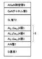
- FIG. 1 is a schematic cross-sectional view showing a laminated structure of a heterojunction FET epitaxial wafer according to Example 1 of the present invention.
- a Si substrate 1 having a diameter of 4 inches and a thickness of 625 ⁇ m was used.
- the surface oxide film of the Si substrate 1 was removed with a hydrofluoric acid-based etchant, and then the substrate was set in an MOCVD (metal organic vapor deposition) apparatus.
- MOCVD metal organic vapor deposition
- the substrate was heated to 1100 ° C., and the surface of the substrate was cleaned in a hydrogen atmosphere with a chamber internal pressure of 13.3 kPa. Thereafter, nitriding of the Si substrate surface was performed by flowing ammonia NH3 (12.5 slm) while maintaining the substrate temperature and the pressure in the chamber.
- TMG trimethylgallium
- a 1 ⁇ m superlattice (SL) buffer layer structure 7 was formed.
- Example 1 the single GaN channel layer 8 was deposited. However, in order to improve the withstand voltage of the formed FET, the thickness of 0.3 ⁇ m deposited under a relatively low reaction gas pressure is used. A channel layer having a two-layer structure including a GaN layer having a thickness of 0.7 ⁇ m and deposited under a relatively high reaction gas pressure with the GaN layer may be formed. In this case, when the reaction gas pressure is low, carbon contained in TMG is easily doped into the GaN channel layer, and conversely, when the reaction gas pressure is high, the GaN channel layer is not easily doped with carbon. The withstand voltage is improved.
- An electron supply layer consisting of (20 nm thick) was deposited.
- an extremely thin AlN characteristic improving layer (1 nm thickness) is added between the GaN channel layer 8 and the Al0.2Ga0.8N barrier layer 9 to increase the 2DEG concentration in the GaN channel layer.
- an extremely thin AlN characteristic improving layer (1 nm thickness) is added between the GaN channel layer 8 and the Al0.2Ga0.8N barrier layer 9 to increase the 2DEG concentration in the GaN channel layer.
- FIG. 2 is a schematic cross-sectional view showing a laminated structure of an epitaxial wafer for a heterojunction FET according to Comparative Example 1.
- the substrate temperature is set to 1150 ° C., and an AlN superlattice constituting layer having a thickness of 10 nm and a GaN superlattice constituting layer having a thickness of 20 nm are laminated in 70 cycles. It was done.
- Example 2 Thereafter, as in Example 1, an electron supply layer of GaN channel layer 8 (thickness: 1000 nm) and Al0.2Ga0.8N barrier layer 9 (thickness: 20 nm) was deposited.
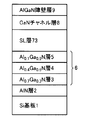
- FIG. 3 is a schematic cross-sectional view showing a laminated structure of an epitaxial wafer for a heterojunction FET according to Comparative Example 2.
- the layers other than the layer included in the superlattice (SL) buffer layer structure 73 were deposited under the same conditions as in Example 1.
- the substrate temperature was set to 1150 ° C., and an AlN superlattice constituent layer having a thickness of 10 nm and an Al0.2Ga0.8N superlattice constituent layer having a thickness of 20 nm were formed. 70 cycles were laminated.
- Example 2 Thereafter, as in Example 1, an electron supply layer of GaN channel layer 8 (thickness: 1000 nm) and Al0.2Ga0.8N barrier layer 9 (thickness: 20 nm) was deposited.
- Warpage and edge dislocation density were evaluated in the epitaxial wafers according to the examples and comparative examples as described above.
- the warpage of a wafer having a diameter of 4 inches is measured by adding the amount of warpage of the central portion convex downward.
- FWHM and edge dislocation density were related by observation by cathodoluminescence (CL).
- the numerical value “9.0” in the equation (1) is a fitting parameter that relates FWHM and edge dislocation density based on CL observation, and 3.189 ⁇ is the bar gas vector of the edge dislocation in the GaN crystal. Length.
- the composition of the uppermost layer in the stepwise composition gradient buffer layer structure is AlxGa1-xN (0 ⁇ x)
- the composition of the superlattice constituent layer having a relatively large band gap in the superlattice buffer layer structure is AlyGa1-
- yN (y ⁇ 1) and the composition of the superlattice constituent layer having a relatively small band gap is AlzGa1-zN (0 ⁇ z ⁇ y)
- Example 1 the uppermost layer of 6 in the graded composition graded buffer layer structure for the small band gap Al0.1Ga0.9N superlattice constituent layer in the superlattice buffer layer structure 7.
- the Al composition difference of the Al0.1Ga0.9N layer 5 was 0%.
- the amount of warpage of the wafer was 2.0 ⁇ m.
- the edge dislocation density in the wafer was 2.44 ⁇ 109 cm ⁇ 2.
- Comparative Example 1 the Al composition difference of the uppermost Al0.1Ga0.9N layer 5 in the stepwise composition gradient buffer layer structure with respect to the GaN superlattice constituent layer with a small band gap in the superlattice buffer layer structure 71 was ⁇ 10%, and in this case, the amount of warpage of the wafer was 44.8 ⁇ m.
- the edge dislocation density in the wafer was 6.15 ⁇ 10 9 cm ⁇ 2.
- the uppermost Al0.1Ga0.9N layer 5 in the graded composition graded buffer layer structure for the small band gap Al0.2Ga0.8N superlattice constituent layer in the superlattice buffer layer structure 72 The Al composition difference was + 10%, and in this case, the amount of warpage of the wafer was 67.4 ⁇ m. Further, the edge dislocation density in the wafer was 3.45 ⁇ 109 cm ⁇ 2.
- the warp of the epitaxial wafer is 20 ⁇ m or less
- the wafer can be easily handled in the semiconductor manufacturing process, and for example, a GaN-based low on-resistance small power device can be easily manufactured. Therefore, if the composition ratio difference is ⁇ 0.05 ⁇ z ⁇ x ⁇ 0.05, it can be used as a practical epitaxial wafer.
- the Al0.1Ga0.9N layer 5 was used as the uppermost layer in the composition gradient buffer layer structure 6, but the Al0.2Ga0.8N layer was used as the uppermost layer.
- the same tendency as in FIG. 4 was confirmed.
- the AlGaN layer has a lattice constant intermediate between those of the GaN layer and the AlN layer.
- the Al composition of the superlattice constituent layer with the smaller band gap in the superlattice buffer layer structure substantially the same as the Al composition of the uppermost layer in the graded graded buffer layer, It is considered that the distortion between the inclined buffer layer structure and the warp generated in the wafer can be further minimized.
- the superlattice buffer layer structure preferably includes an AlN superlattice constituting layer having as large a band gap as possible.
- the warpage of the nitride-based semiconductor epitaxial wafer can be greatly reduced, and the edge dislocations can be reduced. It is possible to provide a nitride-based semiconductor epitaxial wafer having a reduced density.
Abstract
This epitaxial wafer for a heterojunction field-effect transistor (FET) contains, layered in order on a Si substrate, an AlN base layer, a step-graded buffer layer structure, a superlattice buffer layer structure, a GaN channel layer, and an electron supply layer of a nitride semiconductor. The step-graded buffer layer structure contains a plurality of AlGaN buffer layers that are layered such that the Al composition ratio sequentially decreases, and the uppermost layer thereof has a composition of AlxGa1-xN(O<x). The inside of the superlattice buffer layer structure starts from either an AlyGa1-yN(y≤1) superlattice structure layer or an AlzGa1-zN(O<z<y) superlattice structure layer and has these two superlattice structure layers alternately layered multiple times therein. The AlxGa1-xN buffer layer and the AlzGal-zN superlattice structure layer satisfy the condition x-0.05≤z≤x+0.05.
Description
本発明は、2次元電子ガス(2DEG)を生じ得る複数の窒化物系半導体層を含むヘテロ接合型電界効果トランジスタを作製するためのエピタキシャルウエハに関し、特にそのウエハにおける反りと転位密度の低減に関する。
The present invention relates to an epitaxial wafer for producing a heterojunction field effect transistor including a plurality of nitride-based semiconductor layers capable of generating a two-dimensional electron gas (2DEG), and particularly to reduction of warpage and dislocation density in the wafer.
窒化物系半導体からなる例えばAlGaN層/GaN層のヘテロ接合構造の形成においては、GaN基板が高価であることから、サファイア基板やSi基板の上におけるそれらの層のエピタキシャル結晶成長が従来から行なわれている。
In the formation of heterojunction structures of, for example, AlGaN layers / GaN layers made of nitride-based semiconductors, GaN substrates are expensive, and epitaxial crystal growth of those layers on sapphire substrates and Si substrates has been conventionally performed. ing.
Si基板上の窒化物系半導体層の結晶成長に関しては、Si基板に対する窒化物系半導体層の結晶構造の相違、格子不整合、熱膨張係数差などに基づく歪みを緩和するために、さまざまなバッファ層構造が検討されている。より具体的には、2種の超格子構成層の繰返しを含む超格子バッファ層構造に関して、多くの特許公報が存在している。
With respect to crystal growth of nitride-based semiconductor layers on Si substrates, various buffers are used to alleviate strains based on differences in the crystal structure of the nitride-based semiconductor layers relative to the Si substrate, lattice mismatch, thermal expansion coefficient differences, etc. Layer structure is being considered. More specifically, many patent publications exist regarding a superlattice buffer layer structure including repetition of two types of superlattice constituent layers.
例えば、特許文献1では、格子定数および熱膨張率が大きく異なる基板上に表面が平滑でクラックを含まない窒化物半導体層を形成することを目的として、シリコン基板上にAlxGa1-xN(0.5≦x≦1)の第1超格子構成層とAlyGa1-yN(0.01≦y≦0.2)の第2超格子構成層とを交互に繰返し積層してAlGaN系超格子バッファ層構造を形成することが記載されている。
For example, in Patent Document 1, AlxGa1-xN (0.5) is formed on a silicon substrate for the purpose of forming a nitride semiconductor layer having a smooth surface and containing no cracks on a substrate having greatly different lattice constants and thermal expansion coefficients. ≦ x ≦ 1) first superlattice constituent layers and AlyGa1-yN (0.01 ≦ y ≦ 0.2) second superlattice constituent layers are alternately and repeatedly stacked to form an AlGaN superlattice buffer layer structure. It is described to form.
また、特許文献2では、バッファ層を介する電極間の電流リークを抑制することを目的として、シリコン基板上のAlNバッファ層と、その上に交互に積層された高Al組成比のH-AlGaN超格子構成層と低Al組成比のL-AlGaN超格子構成層を含む超格子バッファ層構造とを有する半導体素子が記載されている。
Further, in Patent Document 2, in order to suppress current leakage between electrodes through the buffer layer, an AlN buffer layer on a silicon substrate and a high Al composition ratio H—AlGaN superlayer alternately stacked thereon are formed. A semiconductor device having a lattice structure layer and a superlattice buffer layer structure including an L-AlGaN superlattice structure layer having a low Al composition ratio is described.
さらに、特許文献3では、Si基板上またはこの上に形成した中間層上に、Al組成比が厚さ方向に連続または段階的に減少させられた組成傾斜バッファ層構造を形成し、その上に交互に積層された高Al組成比のAlGaN超格子構成層と低Al組成比のAlGaN超格子構成層と含む超格子バッファ層構造を形成し、その上にチャネル層となる窒化物層が形成されている。このような積層構造を利用することによって、クラックおよびピットの発生が少なくかつ結晶性に優れた窒化物半導体層を有する半導体素子が得られることが述べられている。
Furthermore, in Patent Document 3, a composition gradient buffer layer structure in which the Al composition ratio is continuously or stepwise decreased in the thickness direction is formed on an Si substrate or an intermediate layer formed on the Si substrate. A superlattice buffer layer structure including AlGaN superlattice constituent layers with high Al composition ratios and AlGaN superlattice constituent layers with low Al composition ratios, which are alternately stacked, is formed, and a nitride layer serving as a channel layer is formed thereon. ing. It is stated that by using such a laminated structure, a semiconductor element having a nitride semiconductor layer with few cracks and pits and excellent crystallinity can be obtained.
特許文献1から3に開示された窒化物系半導体エピタキシャルウエハは、電子デバイスであるパワーデバイス用のウエハとして用いることができることが記載または示唆されている。しかしながら、そのようなエピタキシャルウエハを用いてパワーデバイスを製造するためには、そのウエハに対してフォトリソグラフィやエッチングなどの工程を通して、電極形成、素子分離、表面保護膜形成、内部配線形成などの半導体処理プロセスを経る必要がある。したがって、ウエハに反りがある場合にはデバイスの歩留まりの低下を招き、反りがひどい場合にはウエハを半導体製造装置で処理できないという問題を生じる。特に、600Vから1200Vまでの耐電圧が求められるパワーデバイスの場合には、窒化物半導体層自体の膜厚を増大させる必要があり、その膜厚の増大に伴ってウエハの反りが大きくなる傾向にある。
It is described or suggested that the nitride-based semiconductor epitaxial wafer disclosed in Patent Documents 1 to 3 can be used as a wafer for a power device that is an electronic device. However, in order to manufacture a power device using such an epitaxial wafer, semiconductors such as electrode formation, element isolation, surface protection film formation, and internal wiring formation are performed on the wafer through processes such as photolithography and etching. It is necessary to go through a processing process. Therefore, when the wafer is warped, the yield of the device is lowered, and when the warpage is severe, the wafer cannot be processed by the semiconductor manufacturing apparatus. In particular, in the case of a power device that requires a withstand voltage of 600 V to 1200 V, it is necessary to increase the film thickness of the nitride semiconductor layer itself, and the warpage of the wafer tends to increase as the film thickness increases. is there.
このようなウエハの反りの問題から、パワーデバイスを製造するに適したエピタキシャルウエハは、未だ市場に出ていないのが現状である。
Due to the problem of warpage of the wafer, an epitaxial wafer suitable for manufacturing a power device has not yet been put on the market.
上述のような先行技術における課題に鑑み、本発明は、段階的組成傾斜バッファ層構造とその上の超格子バッファ層構造との関係を調整することによって、ヘテロ接合型FET用のエピタキシャルウエハにおける反りと刃状転位密度を低減させることを目的としている。
In view of the problems in the prior art as described above, the present invention provides a warp in an epitaxial wafer for a heterojunction FET by adjusting the relationship between a graded compositionally graded buffer layer structure and a superlattice buffer layer structure thereon. The purpose is to reduce the edge dislocation density.
本発明によれば、ヘテロ接合型電界効果トランジスタ用のエピタキシャルウエハは、Si基板上に順次積層されたAlN下地層、段階的組成傾斜バッファ層構造、超格子バッファ層構造、GaNチャネル層、および窒化物系半導体の電子供給層を含み、段階的組成傾斜バッファ層構造はAl組成比が段階的に順次低減されるように積層された複数のAlGaNバッファ層を含み、最上のAlGaNバッファ層はAlxGa1-xN(0<x)の組成を有し、超格子バッファ層構造内ではAlyGa1-yN(y≦1)超格子構成層とAlzGa1-zN(0<z<y)超格子構成層のいずれかから開始してそれらの超格子構成層が交互に複数回積層されており、AlxGa1-xNバッファ層とAlzGa1-zN超格子構成層とがほぼ同じAl組成比を有していてx-0.05≦z≦x+0.05の条件を満たすことを特徴としている。
According to the present invention, an epitaxial wafer for a heterojunction field effect transistor includes an AlN underlayer sequentially laminated on a Si substrate, a graded compositionally graded buffer layer structure, a superlattice buffer layer structure, a GaN channel layer, and a nitridation layer A step-gradient compositionally graded buffer layer structure including a plurality of AlGaN buffer layers stacked so that the Al composition ratio is sequentially reduced, and the uppermost AlGaN buffer layer is an AlxGa1- xN (0 <x), and within the superlattice buffer layer structure, either an AlyGa1-yN (y ≦ 1) superlattice constituent layer or an AlzGa1-zN (0 <z <y) superlattice constituent layer The superlattice constituent layers are alternately stacked several times from the beginning, and the AlxGa1-xN buffer layer and the AlzGa1-zN superlattice constituent layer are substantially the same Al. It has a composition ratio and satisfies the condition of x−0.05 ≦ z ≦ x + 0.05.
なお、超格子バッファ層構造内の最下の超格子構成層は、AlNの組成を有することが好ましい。
Note that the lowermost superlattice constituent layer in the superlattice buffer layer structure preferably has an AlN composition.
上述のような本発明による段階的組成傾斜バッファ層構造および超格子バッファ層構造の組合せを利用することよって、窒化物系半導体エピタキシャルウエハの反りを大幅に低減させることができ、また刃状転位密度も低減された窒化物系半導体エピタキシャルウエハを得ることが可能となる。
By utilizing the combination of the graded composition graded buffer layer structure and the superlattice buffer layer structure according to the present invention as described above, the warpage of the nitride-based semiconductor epitaxial wafer can be greatly reduced, and the edge dislocation density can be reduced. It is also possible to obtain a nitride-based semiconductor epitaxial wafer with reduced resistance.
本発明者達は、ヘテロ接合型FET用のエピタキシャルウエハにおける反りと刃状転位密度の低減を図るために望まれる段階的組成傾斜バッファ層構造と超格子バッファ層構造との関係を解明するために、以下に述べるような実施例と比較例によるウエハにおける反り量と刃状転位密度を測定し、その結果について考察して本発明を導き出した。
In order to elucidate the relationship between the stepwise composition gradient buffer layer structure and the superlattice buffer layer structure, which are desired to reduce the warpage and the edge dislocation density in the epitaxial wafer for the heterojunction FET. The amount of warpage and edge dislocation density in wafers according to Examples and Comparative Examples as described below were measured, and the present invention was derived by considering the results.
(実施例1)
図1は、本発明の実施例1によるヘテロ接合型FET用エピタキシャルウエハの積層構造を示す模式的断面図である。 Example 1
FIG. 1 is a schematic cross-sectional view showing a laminated structure of a heterojunction FET epitaxial wafer according to Example 1 of the present invention.
図1は、本発明の実施例1によるヘテロ接合型FET用エピタキシャルウエハの積層構造を示す模式的断面図である。 Example 1
FIG. 1 is a schematic cross-sectional view showing a laminated structure of a heterojunction FET epitaxial wafer according to Example 1 of the present invention.
この図1のウエハの作製においては、4インチ径で厚さ625μmのSi基板1が用いられた。窒化物系半導体層の結晶成長に先立って、フッ酸系のエッチャントでSi基板1の表面酸化膜を除去した後に、MOCVD(有機金属気相堆積)装置内にその基板がセットされた。MOCVD装置内では基板が1100℃に加熱され、チャンバ内圧力13.3kPaの水素雰囲気にて基板表面のクリーニングが行なわれた。その後、基板温度とチャンバ内圧力を維持しつつ、アンモニアNH3(12.5slm)を流すことによって、Si基板表面の窒化が行なわれた。
In the production of the wafer shown in FIG. 1, a Si substrate 1 having a diameter of 4 inches and a thickness of 625 μm was used. Prior to crystal growth of the nitride-based semiconductor layer, the surface oxide film of the Si substrate 1 was removed with a hydrofluoric acid-based etchant, and then the substrate was set in an MOCVD (metal organic vapor deposition) apparatus. In the MOCVD apparatus, the substrate was heated to 1100 ° C., and the surface of the substrate was cleaned in a hydrogen atmosphere with a chamber internal pressure of 13.3 kPa. Thereafter, nitriding of the Si substrate surface was performed by flowing ammonia NH3 (12.5 slm) while maintaining the substrate temperature and the pressure in the chamber.
Si基板表面の窒化に引き続いて、TMA(トリメチルアルミニウム)流量=117μmol/minとNH3流量=12.5slmの条件下で、AlN下地層2が200nmの厚さに堆積された。
Subsequent to nitridation of the Si substrate surface, an AlN underlayer 2 was deposited to a thickness of 200 nm under the conditions of TMA (trimethylaluminum) flow rate = 117 μmol / min and NH 3 flow rate = 12.5 slm.
その後、基板温度を1150℃に上昇させ、下記条件下で段階的組成傾斜バッファ層構造6が形成された。すなわち、TMG(トリメチルガリウム)流量=57μmol/min、TMA流量=97μmol/minおよびNH3流量=12.5slmの条件下で、Al0.7Ga0.3N層3が200nmの厚さに堆積された。続いて、TMG流量=99μmol/min、TMA流量=55μmol/minおよびNH3流量=12.5slmの条件下で、Al0.4Ga0.6N層4が400nmの厚さに堆積され、さらにTMG流量=137μmol/min、TMA流量=18μmol/minおよびNH3流量=12.5slmの条件下で、Al0.1Ga0.9N層5が400nmの厚さに堆積された。こうして、段階的組成傾斜バッファ層構造6が形成された。
Thereafter, the substrate temperature was raised to 1150 ° C., and the graded composition gradient buffer layer structure 6 was formed under the following conditions. That is, the Al0.7Ga0.3N layer 3 was deposited to a thickness of 200 nm under the conditions of TMG (trimethylgallium) flow rate = 57 μmol / min, TMA flow rate = 97 μmol / min, and NH 3 flow rate = 12.5 slm. Subsequently, an Al0.4Ga0.6N layer 4 was deposited to a thickness of 400 nm under the conditions of TMG flow rate = 99 μmol / min, TMA flow rate = 55 μmol / min, and NH 3 flow rate = 12.5 slm, and TMG flow rate = 137 μmol / min. Under conditions of min, TMA flow rate = 18 μmol / min and NH 3 flow rate = 12.5 slm, an Al0.1Ga0.9N layer 5 was deposited to a thickness of 400 nm. Thus, the graded composition gradient buffer layer structure 6 was formed.
その後に、基板温度を1150℃に維持したままで、厚さ10nmのAlN超格子構成層と厚さ20nmのAl0.1Ga0.9N超格子構成層とを70周期積層することによって、厚さ2.1μmの超格子(SL)バッファ層構造7が形成された。このとき、AlN超格子構成層はTMA流量=102μmol/minおよびNH3流量=12.5slmの条件下で堆積され、Al0.1Ga0.9N超格子構成層はTMG流量=720μmol/min、TMA流量=80μmol/minおよびNH3流量=12.5slmの条件下で堆積された。
Thereafter, while maintaining the substrate temperature at 1150 ° C., 70 cycles of an AlN superlattice constituent layer having a thickness of 10 nm and an Al0.1Ga0.9N superlattice constituent layer having a thickness of 20 nm are laminated by a thickness of 2. A 1 μm superlattice (SL) buffer layer structure 7 was formed. At this time, the AlN superlattice constituting layer is deposited under the conditions of TMA flow rate = 102 μmol / min and NH 3 flow rate = 12.5 slm, and the Al0.1Ga0.9N superlattice constituting layer is TMG flow rate = 720 μmol / min, TMA flow rate = 80 μmol. / Min and NH3 flow rate = 12.5 slm.
その後に基板温度が1100℃に下げられ、TMG流量=224μmol/minおよびNH3流量=12.5slmの条件下で、GaNチャネル層8が1000nmに堆積された。
Thereafter, the substrate temperature was lowered to 1100 ° C., and the GaN channel layer 8 was deposited to 1000 nm under the conditions of TMG flow rate = 224 μmol / min and NH 3 flow rate = 12.5 slm.
なお、本実施例1では単一のGaNチャネル層8が堆積されたが、形成されるFETの耐電圧を向上させるために、相対的に低い反応ガス圧下で堆積される厚さ0.3μmのGaN層と相対的に高い反応ガス圧下で堆積される厚さ0.7μmのGaN層を含む2層構造のチャネル層が形成されてもよい。この場合に、反応ガス圧が低いときにはTMGに含まれる炭素がGaNチャネル層内にドープされやすく、逆に反応ガス圧が高いときにはGaNチャネル層内に炭素がドープされにくい傾向を利用することによってFETの耐電圧の向上が図られる。
In Example 1, the single GaN channel layer 8 was deposited. However, in order to improve the withstand voltage of the formed FET, the thickness of 0.3 μm deposited under a relatively low reaction gas pressure is used. A channel layer having a two-layer structure including a GaN layer having a thickness of 0.7 μm and deposited under a relatively high reaction gas pressure with the GaN layer may be formed. In this case, when the reaction gas pressure is low, carbon contained in TMG is easily doped into the GaN channel layer, and conversely, when the reaction gas pressure is high, the GaN channel layer is not easily doped with carbon. The withstand voltage is improved.
GaNチャネル層8上には、TMG流量=46μmol/min、TMA流量=7μmol/minおよびNH3流量=12.5slmの条件下で、13.3kPaの圧力の下で、Al0.2Ga0.8N障壁層9(20nm厚)からなる電子供給層が堆積された。
On the GaN channel layer 8, an Al0.2Ga0.8N barrier layer 9 is formed under the conditions of TMG flow rate = 46 μmol / min, TMA flow rate = 7 μmol / min, and NH 3 flow rate = 12.5 slm under a pressure of 13.3 kPa. An electron supply layer consisting of (20 nm thick) was deposited.
なお、電子供給層としては、GaNチャネル層8とAl0.2Ga0.8N障壁層9との間に極めて薄いAlN特性改善層(1nm厚)を付加することによってGaNチャネル層中の2DEG濃度を高める工夫をしてもよいし、Al0.2Ga0.8N障壁層9の表面を保護する目的でその上にGaNキャップ層(1nm厚)を設けることも好ましい。
As an electron supply layer, an extremely thin AlN characteristic improving layer (1 nm thickness) is added between the GaN channel layer 8 and the Al0.2Ga0.8N barrier layer 9 to increase the 2DEG concentration in the GaN channel layer. For the purpose of protecting the surface of the Al0.2Ga0.8N barrier layer 9, it is also preferable to provide a GaN cap layer (1 nm thick) thereon.
(比較例1)
図2は、比較例1によるヘテロ接合型FET用のエピタキシャルウエハの積層構造を示す模式的断面図である。 (Comparative Example 1)
FIG. 2 is a schematic cross-sectional view showing a laminated structure of an epitaxial wafer for a heterojunction FET according to Comparative Example 1.
図2は、比較例1によるヘテロ接合型FET用のエピタキシャルウエハの積層構造を示す模式的断面図である。 (Comparative Example 1)
FIG. 2 is a schematic cross-sectional view showing a laminated structure of an epitaxial wafer for a heterojunction FET according to Comparative Example 1.
図2のウエハの作製では、超格子(SL)バッファ層構造72に含まれる層以外の層は、実施例1の場合と同じ条件で堆積された。
2, layers other than the layer included in the superlattice (SL) buffer layer structure 72 were deposited under the same conditions as in Example 1.
本比較例1の超格子バッファ層構造72の形成においては、基板温度を1150℃に設定して、厚さ10nmのAlN超格子構成層と厚さ20nmのGaN超格子構成層とが70周期積層された。このとき、AlN超格子構成層はTMA流量=102μmol/minおよびNH3流量=12.5slmの条件下で堆積され、GaN層はTMG流量=800μmol/minおよびNH3流量=12.5slmの条件下で堆積された。
In the formation of the superlattice buffer layer structure 72 of the present comparative example 1, the substrate temperature is set to 1150 ° C., and an AlN superlattice constituting layer having a thickness of 10 nm and a GaN superlattice constituting layer having a thickness of 20 nm are laminated in 70 cycles. It was done. At this time, the AlN superlattice constituent layer is deposited under the conditions of TMA flow rate = 102 μmol / min and NH 3 flow rate = 12.5 slm, and the GaN layer is deposited under the conditions of TMG flow rate = 800 μmol / min and NH 3 flow rate = 12.5 slm. It was done.
その後、実施例1の場合と同様に、GaNチャネル層8(1000nm厚)およびAl0.2Ga0.8N障壁層9(20nm厚)の電子供給層が堆積された。
Thereafter, as in Example 1, an electron supply layer of GaN channel layer 8 (thickness: 1000 nm) and Al0.2Ga0.8N barrier layer 9 (thickness: 20 nm) was deposited.
(比較例2)
図3は、比較例2によるヘテロ接合型FET用のエピタキシャルウエハの積層構造を示す模式的断面図である。 (Comparative Example 2)
FIG. 3 is a schematic cross-sectional view showing a laminated structure of an epitaxial wafer for a heterojunction FET according to Comparative Example 2.
図3は、比較例2によるヘテロ接合型FET用のエピタキシャルウエハの積層構造を示す模式的断面図である。 (Comparative Example 2)
FIG. 3 is a schematic cross-sectional view showing a laminated structure of an epitaxial wafer for a heterojunction FET according to Comparative Example 2.
図3のウエハの作製においは、超格子(SL)バッファ層構造73に含まれる層以外の層は、実施例1の場合と同じ条件で堆積された。
3, the layers other than the layer included in the superlattice (SL) buffer layer structure 73 were deposited under the same conditions as in Example 1.
本比較例2の超格子バッファ層構造73の形成においては、基板温度を1150℃に設定し、厚さ10nmのAlN超格子構成層と厚さ20nmのAl0.2Ga0.8N超格子構成層とが70周期積層された。このとき、AlN超格子構成層はTMA流量=102μmol/minおよびNH3流量=12.5slmの条件下で堆積され、Al0.2Ga0.8N超格子構成層はTMG流量=640μmol/min、TMA流量=160μmol/minおよびNH3流量=12.5slmの条件下で堆積された。
In the formation of the superlattice buffer layer structure 73 of Comparative Example 2, the substrate temperature was set to 1150 ° C., and an AlN superlattice constituent layer having a thickness of 10 nm and an Al0.2Ga0.8N superlattice constituent layer having a thickness of 20 nm were formed. 70 cycles were laminated. At this time, the AlN superlattice constituting layer is deposited under the conditions of TMA flow rate = 102 μmol / min and NH 3 flow rate = 12.5 slm, and the Al0.2Ga0.8N superlattice constituting layer is TMG flow rate = 640 μmol / min, TMA flow rate = 160 μmol. / Min and NH3 flow rate = 12.5 slm.
その後、実施例1の場合と同様に、GaNチャネル層8(1000nm厚)およびAl0.2Ga0.8N障壁層9(20nm厚)の電子供給層が堆積された。
Thereafter, as in Example 1, an electron supply layer of GaN channel layer 8 (thickness: 1000 nm) and Al0.2Ga0.8N barrier layer 9 (thickness: 20 nm) was deposited.
(評価および考察)
以上のような実施例および比較例によるエピタキシャルウエハにおいて反りと刃状転位密度が評価された。 (Evaluation and discussion)
Warpage and edge dislocation density were evaluated in the epitaxial wafers according to the examples and comparative examples as described above.
以上のような実施例および比較例によるエピタキシャルウエハにおいて反りと刃状転位密度が評価された。 (Evaluation and discussion)
Warpage and edge dislocation density were evaluated in the epitaxial wafers according to the examples and comparative examples as described above.
なお、4インチ径のウエハの反りは、下に凸の中央部の反り量をプラスとして測定されている。また、刃状転位密度は、GaNチャネル層8中の転位密度として測定されている。より具体的には、刃状転位密度は、X線回折測定によるロッキングカーブの(1-100)面回折ピークの半値全幅(FWHM)を用いる下記の実験式(1)から見積もられている。
刃状転位密度=(FWHM2/9.0)/3.189Å2 ・・・(1)
ここで、FWHMと刃状転位密度とは、カソードルミネッセンス(CL)による観察によって関係付けられた。式(1)中の数値「9.0」は、FWHMと刃状転位密度とをCL観察に基づいて関係付けるフィティングパラメータであり、3.189ÅはGaN結晶中の刃状転位のバーガスベクトルの長さである。 Note that the warpage of a wafer having a diameter of 4 inches is measured by adding the amount of warpage of the central portion convex downward. The edge dislocation density is measured as the dislocation density in the GaN channel layer 8. More specifically, the edge dislocation density is estimated from the following empirical formula (1) using the full width at half maximum (FWHM) of the (1-100) plane diffraction peak of the rocking curve by X-ray diffraction measurement.
Edge dislocation density = (FWHM2 / 9.0) /3.189Å2 (1)
Here, FWHM and edge dislocation density were related by observation by cathodoluminescence (CL). The numerical value “9.0” in the equation (1) is a fitting parameter that relates FWHM and edge dislocation density based on CL observation, and 3.189Å is the bar gas vector of the edge dislocation in the GaN crystal. Length.
図4のグラフにおいては、超格子バッファ層構造中で相対的に小さなバンドギャップ(小さなAl組成比)を有する超格子構成層に対する段階的組成傾斜バッファ層構造中の最上層のAl組成差(%)に依存するエピタキシャルウエハの反り(μm)が、上述の実施例1および比較例1と2に基づいて示されている。
In the graph of FIG. 4, the Al composition difference (%) of the uppermost layer in the graded composition gradient buffer layer structure with respect to the superlattice constituent layer having a relatively small band gap (small Al composition ratio) in the superlattice buffer layer structure. ) Dependent on the epitaxial wafer is shown based on Example 1 and Comparative Examples 1 and 2 described above.
すなわち、段階的組成傾斜バッファ層構造中の最上層の組成をAlxGa1-xN(0<x)とし、超格子バッファ層構造中で相対的に大きなバンドギャップを有する超格子構成層の組成をAlyGa1-yN(y≦1)とし、かつ相対的に小さなバンドギャップを有する超格子構成層の組成をAlzGa1-zN(0<z<y)とした場合に、図4のグラフの横軸は(z-x)×100%を表している。
That is, the composition of the uppermost layer in the stepwise composition gradient buffer layer structure is AlxGa1-xN (0 <x), and the composition of the superlattice constituent layer having a relatively large band gap in the superlattice buffer layer structure is AlyGa1- When yN (y ≦ 1) and the composition of the superlattice constituent layer having a relatively small band gap is AlzGa1-zN (0 <z <y), the horizontal axis of the graph of FIG. x) × 100%.
このグラフに示されているように、実施例1においては、超格子バッファ層構造7内の小さなバンドギャップのAl0.1Ga0.9N超格子構成層に対する段階的組成傾斜バッファ層構造中6の最上層のAl0.1Ga0.9N層5のAl組成差は0%であって、この場合にウエハの反り量は2.0μmであった。また、そのウエハにおける刃状転位密度は2.44×109cm-2であった。
As shown in this graph, in Example 1, the uppermost layer of 6 in the graded composition graded buffer layer structure for the small band gap Al0.1Ga0.9N superlattice constituent layer in the superlattice buffer layer structure 7. The Al composition difference of the Al0.1Ga0.9N layer 5 was 0%. In this case, the amount of warpage of the wafer was 2.0 μm. The edge dislocation density in the wafer was 2.44 × 109 cm −2.
他方、比較例1においては、超格子バッファ層構造71内の小さなバンドギャップのGaN超格子構成層に対する段階的組成傾斜バッファ層構造中6の最上層のAl0.1Ga0.9N層5のAl組成差は-10%であって、この場合にウエハの反り量は44.8μmであった。また、そのウエハにおける刃状転位密度は6.15×109cm-2であった。
On the other hand, in Comparative Example 1, the Al composition difference of the uppermost Al0.1Ga0.9N layer 5 in the stepwise composition gradient buffer layer structure with respect to the GaN superlattice constituent layer with a small band gap in the superlattice buffer layer structure 71 Was −10%, and in this case, the amount of warpage of the wafer was 44.8 μm. The edge dislocation density in the wafer was 6.15 × 10 9 cm −2.
さらに、比較例2においては、超格子バッファ層構造72内の小さなバンドギャップのAl0.2Ga0.8N超格子構成層に対する段階的組成傾斜バッファ層構造中6の最上層のAl0.1Ga0.9N層5に対するAl組成差は+10%であって、この場合にウエハの反り量は67.4μmであった。また、そのウエハにおける刃状転位密度は3.45×109cm-2であった。
Further, in Comparative Example 2, the uppermost Al0.1Ga0.9N layer 5 in the graded composition graded buffer layer structure for the small band gap Al0.2Ga0.8N superlattice constituent layer in the superlattice buffer layer structure 72 The Al composition difference was + 10%, and in this case, the amount of warpage of the wafer was 67.4 μm. Further, the edge dislocation density in the wafer was 3.45 × 109 cm −2.
以上の結果から、超格子バッファ層構造中の小さなAl組成比の超格子構成層と組成傾斜バッファ層構造中の最上層との間のAl組成差(%)が小さいほど、エピタキシャルウエハにおける反りと刃状転位密度の両方が顕著に減少することが分かる。
From the above results, as the Al composition difference (%) between the superlattice constituent layer having a small Al composition ratio in the superlattice buffer layer structure and the uppermost layer in the composition gradient buffer layer structure is smaller, the warpage in the epitaxial wafer is reduced. It can be seen that both edge dislocation densities are significantly reduced.
ここで、エピタキシャルウエハの反りが20μm以下の場合には、半導体製造プロセスにおいてそのウエハを容易に取扱うことができ、例えばGaN系の低オン抵抗の小型パワーデバイスを容易に作製することができる。したがって、-0.05≦z-x≦0.05の組成比差であれば、実用的なエピタキシャルウエハとして利用可能である。
Here, when the warp of the epitaxial wafer is 20 μm or less, the wafer can be easily handled in the semiconductor manufacturing process, and for example, a GaN-based low on-resistance small power device can be easily manufactured. Therefore, if the composition ratio difference is −0.05 ≦ z−x ≦ 0.05, it can be used as a practical epitaxial wafer.
なお、以上の実施例と比較例においては組成傾斜バッファ層構造中6の最上層としてAl0.1Ga0.9N層5が用いられたが、その最上層としてAl0.2Ga0.8N層が用いられた場合でも、図4と同様の傾向が確認された。
In the above examples and comparative examples, the Al0.1Ga0.9N layer 5 was used as the uppermost layer in the composition gradient buffer layer structure 6, but the Al0.2Ga0.8N layer was used as the uppermost layer. However, the same tendency as in FIG. 4 was confirmed.
以上のような結果となる理由として、以下のような事項が関係していると推察される。まず、比較的大きな厚さを有するGaNチャネル層を直接Si基板上にエピタキシャル成長させた場合、エピタキシャル成長時の高温状態から室温にウエハを冷却するときに、Si基板に比べて大きな熱膨張係数を有するGaN層はSi基板より冷却収縮度が大きくなる。したがって、Si基板の上面はGaN層から圧縮力を受け(GaN層はSi基板から引張り力を受け)、ウエハ全体が下に凸に反ることになる。
It is surmised that the following matters are related as the reason for the above results. First, when a GaN channel layer having a relatively large thickness is directly epitaxially grown on a Si substrate, when the wafer is cooled from the high temperature state during epitaxial growth to room temperature, the GaN has a larger thermal expansion coefficient than the Si substrate. The layer has a higher cooling shrinkage than the Si substrate. Therefore, the upper surface of the Si substrate receives a compressive force from the GaN layer (the GaN layer receives a tensile force from the Si substrate), and the entire wafer is warped downward.
このような状況において、段階的組成傾斜バッファ層構造によって格子定数差による歪を利用してGaN層に圧縮力を順次与えることによって、結果としてウエハ全体の下に凸の反りを軽減させることができる。なお、AlGaN層は、GaN層およびAlN層に比べてそれらの中間の格子定数を有している。
In such a situation, by applying a compressive force sequentially to the GaN layer using strain due to the difference in lattice constant by the stepwise compositionally graded buffer layer structure, it is possible to reduce the convex warpage under the entire wafer as a result. . The AlGaN layer has a lattice constant intermediate between those of the GaN layer and the AlN layer.
さらに、超格子バッファ層構造中でバンドギャップの小さい方の超格子構成層のAl組成を段階的傾斜バッファ層中の最上層のAl組成とほぼ同じにすることによって、超格子バッファ層構造と段階的傾斜バッファ層構造との間の歪を最小限とすることができ、ウエハに生じる反りをさらにミニマイズできると考えられる。
Furthermore, by making the Al composition of the superlattice constituent layer with the smaller band gap in the superlattice buffer layer structure substantially the same as the Al composition of the uppermost layer in the graded graded buffer layer, It is considered that the distortion between the inclined buffer layer structure and the warp generated in the wafer can be further minimized.
なお、高い耐電圧を有するFETを作製するために本発明のエピタキシャルウエハを使用する場合には、超格子バッファ層構造はなるべく大きなバンドギャップのAlN超格子構成層を含むことが好ましい。
Note that when the epitaxial wafer of the present invention is used to fabricate an FET having a high withstand voltage, the superlattice buffer layer structure preferably includes an AlN superlattice constituting layer having as large a band gap as possible.
以上のように、本発明による段階的組成傾斜バッファ層構造と超格子バッファ層構造の組合せを利用することよって、窒化物系半導体エピタキシャルウエハの反りを大幅に低減させることができ、また刃状転位密度も低減された窒化物系半導体エピタキシャルウエハを提供することが可能となる。
As described above, by utilizing the combination of the graded composition graded buffer layer structure and the superlattice buffer layer structure according to the present invention, the warpage of the nitride-based semiconductor epitaxial wafer can be greatly reduced, and the edge dislocations can be reduced. It is possible to provide a nitride-based semiconductor epitaxial wafer having a reduced density.
1 Si基板、2 AlN下地層、3 Al0.7Ga0.3Nバッファ層、4 Al0.4Ga0.6Nバッファ層、5 Al0.1Ga0.9Nバッファ層、6 段階的組成傾斜バッファ層構造、7、72、73 超格子バッファ層構造、8 GaNチャネル層、9 Al0.2Ga0.8N障壁層。
1 Si substrate, 2 AlN underlayer, 3 Al0.7Ga0.3N buffer layer, 4 Al0.4Ga0.6N buffer layer, 5 Al0.1Ga0.9N buffer layer, 6 graded composition gradient buffer layer structure, 7, 72, 73 Superlattice buffer layer structure, 8 GaN channel layer, 9 Al0.2Ga0.8N barrier layer.
Claims (2)
- ヘテロ接合型電界効果トランジスタ用のエピタキシャルウエハであって、
Si基板上に順次積層されたAlN下地層、段階的組成傾斜バッファ層構造、超格子バッファ層構造、GaNチャネル層、および窒化物系半導体の電子供給層を含み、
前記段階的組成傾斜バッファ層構造は、Al組成比が段階的に順次低減されるように積層された複数のAlGaNバッファ層を含み、最上のAlGaNバッファ層はAlxGa1-xN(0<x)の組成を有し、
前記超格子バッファ層構造内ではAlyGa1-yN(y≦1)超格子構成層とAlzGa1-zN(0<z<y)超格子構成層のいずれかから開始してそれらの超格子構成層が交互に複数回積層されており、
前記AlxGa1-xNバッファ層とAlzGa1-zN超格子構成層とがほぼ同じAl組成比を有していてx-0.05≦z≦x+0.05の条件を満たすことを特徴とするエピタキシャルウエハ。 An epitaxial wafer for a heterojunction field effect transistor,
Including an AlN underlayer, a graded compositionally graded buffer layer structure, a superlattice buffer layer structure, a GaN channel layer, and an electron supply layer of a nitride-based semiconductor, which are sequentially stacked on a Si substrate,
The stepwise composition gradient buffer layer structure includes a plurality of AlGaN buffer layers stacked so that the Al composition ratio is sequentially reduced, and the uppermost AlGaN buffer layer has a composition of AlxGa1-xN (0 <x). Have
In the superlattice buffer layer structure, starting from either the AlyGa1-yN (y ≦ 1) superlattice constituent layer or the AlzGa1-zN (0 <z <y) superlattice constituent layer, the superlattice constituent layers are alternated. Are stacked several times,
An epitaxial wafer characterized in that the AlxGa1-xN buffer layer and the AlzGa1-zN superlattice constituting layer have substantially the same Al composition ratio and satisfy the condition of x-0.05≤z≤x + 0.05. - 前記超格子バッファ層構造内の最下の超格子構成層がAlNの組成を有することを特徴とする請求項1に記載のエピタキシャルウエハ。 The epitaxial wafer according to claim 1, wherein the lowermost superlattice constituting layer in the superlattice buffer layer structure has a composition of AlN.
Priority Applications (2)
| Application Number | Priority Date | Filing Date | Title |
|---|---|---|---|
| US14/372,366 US9111839B2 (en) | 2012-01-16 | 2013-01-15 | Epitaxial wafer for heterojunction type field effect transistor |
| CN201380005634.XA CN104054166A (en) | 2012-01-16 | 2013-01-15 | Epitaxial wafer for heterojunction field-effect transistor |
Applications Claiming Priority (2)
| Application Number | Priority Date | Filing Date | Title |
|---|---|---|---|
| JP2012005945A JP5785103B2 (en) | 2012-01-16 | 2012-01-16 | Epitaxial wafers for heterojunction field effect transistors. |
| JP2012-005945 | 2012-01-16 |
Publications (1)
| Publication Number | Publication Date |
|---|---|
| WO2013108733A1 true WO2013108733A1 (en) | 2013-07-25 |
Family
ID=48799158
Family Applications (1)
| Application Number | Title | Priority Date | Filing Date |
|---|---|---|---|
| PCT/JP2013/050519 WO2013108733A1 (en) | 2012-01-16 | 2013-01-15 | Epitaxial wafer for heterojunction field-effect transistor |
Country Status (4)
| Country | Link |
|---|---|
| US (1) | US9111839B2 (en) |
| JP (1) | JP5785103B2 (en) |
| CN (1) | CN104054166A (en) |
| WO (1) | WO2013108733A1 (en) |
Cited By (3)
| Publication number | Priority date | Publication date | Assignee | Title |
|---|---|---|---|---|
| CN104201196A (en) * | 2014-08-13 | 2014-12-10 | 中国电子科技集团公司第五十五研究所 | Si (Silicon)-base III nitride epitaxial wafer without microcracks in surface |
| GB2519338A (en) * | 2013-10-17 | 2015-04-22 | Nanogan Ltd | Crack-free gallium nitride materials |
| WO2016166949A1 (en) * | 2015-04-16 | 2016-10-20 | 株式会社デンソー | Semiconductor wafer and semiconductor device |
Families Citing this family (23)
| Publication number | Priority date | Publication date | Assignee | Title |
|---|---|---|---|---|
| JP2014220407A (en) * | 2013-05-09 | 2014-11-20 | ローム株式会社 | Nitride semiconductor element |
| JP6121806B2 (en) * | 2013-06-07 | 2017-04-26 | 株式会社東芝 | Nitride semiconductor wafer, nitride semiconductor device, and method of manufacturing nitride semiconductor wafer |
| TWI574407B (en) * | 2013-08-16 | 2017-03-11 | 晶元光電股份有限公司 | A semiconductor power device |
| CN103500763B (en) * | 2013-10-15 | 2017-03-15 | 苏州晶湛半导体有限公司 | III nitride semiconductor devices and its manufacture method |
| JP2015103665A (en) * | 2013-11-25 | 2015-06-04 | シャープ株式会社 | Nitride semiconductor epitaxial wafer and nitride semiconductor |
| KR102175320B1 (en) | 2014-04-07 | 2020-11-06 | 엘지이노텍 주식회사 | Light emitting device and lighting system having the same |
| CN104037287B (en) * | 2014-06-10 | 2017-01-11 | 广州市众拓光电科技有限公司 | LED epitaxial wafer grown on Si substrate and preparation method thereof |
| JP2016100471A (en) * | 2014-11-21 | 2016-05-30 | 住友電気工業株式会社 | Semiconductor device and method of manufacturing semiconductor device |
| US10109736B2 (en) * | 2015-02-12 | 2018-10-23 | Taiwan Semiconductor Manufacturing Co., Ltd. | Superlattice buffer structure for gallium nitride transistors |
| US20160359004A1 (en) * | 2015-06-03 | 2016-12-08 | Veeco Instruments, Inc. | Stress control for heteroepitaxy |
| US9577042B1 (en) * | 2015-08-13 | 2017-02-21 | Globalfoundries Inc. | Semiconductor structure with multilayer III-V heterostructures |
| KR102491830B1 (en) * | 2015-11-02 | 2023-01-25 | 엔지케이 인슐레이터 엘티디 | Epitaxial substrate for semiconductor device, semiconductor device, and method for manufacturing epitaxial substrate for semiconductor device |
| JP6653750B2 (en) * | 2016-02-26 | 2020-02-26 | サンケン電気株式会社 | Semiconductor substrate and semiconductor device |
| US9842900B2 (en) | 2016-03-30 | 2017-12-12 | International Business Machines Corporation | Graded buffer layers with lattice matched epitaxial oxide interlayers |
| CN106098749A (en) * | 2016-06-30 | 2016-11-09 | 中国电子科技集团公司第五十五研究所 | AlGaN/GaN heterojunction structure and growing method thereof on a kind of silicon substrate |
| JP6796467B2 (en) * | 2016-11-30 | 2020-12-09 | 住友化学株式会社 | Semiconductor substrate |
| JP6859084B2 (en) * | 2016-11-30 | 2021-04-14 | 住友化学株式会社 | Semiconductor substrate |
| CN108346694B (en) | 2017-01-23 | 2020-10-02 | Imec 非营利协会 | III-N based substrates for power electronics and methods of making same |
| JP6781095B2 (en) | 2017-03-31 | 2020-11-04 | エア・ウォーター株式会社 | Compound semiconductor substrate |
| CN112820773A (en) * | 2019-11-18 | 2021-05-18 | 联华电子股份有限公司 | High electron mobility transistor |
| CN112768512A (en) * | 2021-01-13 | 2021-05-07 | 西安电子科技大学 | AlGaN-based double-channel Schottky diode based on groove anode structure and preparation method |
| CN113380930B (en) * | 2021-06-11 | 2022-08-19 | 厦门士兰明镓化合物半导体有限公司 | Deep ultraviolet light emitting diode and manufacturing method thereof |
| CN114361302B (en) * | 2022-03-17 | 2022-06-17 | 江西兆驰半导体有限公司 | Light-emitting diode epitaxial wafer, light-emitting diode buffer layer and preparation method thereof |
Citations (4)
| Publication number | Priority date | Publication date | Assignee | Title |
|---|---|---|---|---|
| JP2005512327A (en) * | 2001-12-03 | 2005-04-28 | クリー インコーポレイテッド | Heterojunction transistor and manufacturing method thereof |
| JP2006100501A (en) * | 2004-09-29 | 2006-04-13 | Sanken Electric Co Ltd | Plate type substrate for using to form semiconductor element and its manufacturing method |
| WO2007077666A1 (en) * | 2005-12-28 | 2007-07-12 | Nec Corporation | Field effect transistor, and multilayered epitaxial film for use in preparation of field effect transistor |
| JP2009158804A (en) * | 2007-12-27 | 2009-07-16 | Dowa Electronics Materials Co Ltd | Semiconductor material, method for manufacturing semiconductor material, and semiconductor element |
Family Cites Families (9)
| Publication number | Priority date | Publication date | Assignee | Title |
|---|---|---|---|---|
| US7112830B2 (en) * | 2002-11-25 | 2006-09-26 | Apa Enterprises, Inc. | Super lattice modification of overlying transistor |
| JP2007067077A (en) | 2005-08-30 | 2007-03-15 | Nippon Telegr & Teleph Corp <Ntt> | Nitride semiconductor device and method of manufacturing same |
| US7598108B2 (en) * | 2007-07-06 | 2009-10-06 | Sharp Laboratories Of America, Inc. | Gallium nitride-on-silicon interface using multiple aluminum compound buffer layers |
| US8674407B2 (en) * | 2008-03-12 | 2014-03-18 | Renesas Electronics Corporation | Semiconductor device using a group III nitride-based semiconductor |
| JP4677499B2 (en) * | 2008-12-15 | 2011-04-27 | Dowaエレクトロニクス株式会社 | Epitaxial substrate for electronic device and manufacturing method thereof |
| JP5634681B2 (en) | 2009-03-26 | 2014-12-03 | 住友電工デバイス・イノベーション株式会社 | Semiconductor element |
| JP5473445B2 (en) * | 2009-07-17 | 2014-04-16 | シャープ株式会社 | Epitaxial wafer |
| JP5708187B2 (en) * | 2011-04-15 | 2015-04-30 | サンケン電気株式会社 | Semiconductor device |
| JP2013026321A (en) * | 2011-07-19 | 2013-02-04 | Sharp Corp | Epitaxial wafer including nitride-based semiconductor layer |
-
2012
- 2012-01-16 JP JP2012005945A patent/JP5785103B2/en active Active
-
2013
- 2013-01-15 WO PCT/JP2013/050519 patent/WO2013108733A1/en active Application Filing
- 2013-01-15 US US14/372,366 patent/US9111839B2/en active Active
- 2013-01-15 CN CN201380005634.XA patent/CN104054166A/en active Pending
Patent Citations (4)
| Publication number | Priority date | Publication date | Assignee | Title |
|---|---|---|---|---|
| JP2005512327A (en) * | 2001-12-03 | 2005-04-28 | クリー インコーポレイテッド | Heterojunction transistor and manufacturing method thereof |
| JP2006100501A (en) * | 2004-09-29 | 2006-04-13 | Sanken Electric Co Ltd | Plate type substrate for using to form semiconductor element and its manufacturing method |
| WO2007077666A1 (en) * | 2005-12-28 | 2007-07-12 | Nec Corporation | Field effect transistor, and multilayered epitaxial film for use in preparation of field effect transistor |
| JP2009158804A (en) * | 2007-12-27 | 2009-07-16 | Dowa Electronics Materials Co Ltd | Semiconductor material, method for manufacturing semiconductor material, and semiconductor element |
Cited By (3)
| Publication number | Priority date | Publication date | Assignee | Title |
|---|---|---|---|---|
| GB2519338A (en) * | 2013-10-17 | 2015-04-22 | Nanogan Ltd | Crack-free gallium nitride materials |
| CN104201196A (en) * | 2014-08-13 | 2014-12-10 | 中国电子科技集团公司第五十五研究所 | Si (Silicon)-base III nitride epitaxial wafer without microcracks in surface |
| WO2016166949A1 (en) * | 2015-04-16 | 2016-10-20 | 株式会社デンソー | Semiconductor wafer and semiconductor device |
Also Published As
| Publication number | Publication date |
|---|---|
| CN104054166A (en) | 2014-09-17 |
| JP2013145821A (en) | 2013-07-25 |
| JP5785103B2 (en) | 2015-09-24 |
| US9111839B2 (en) | 2015-08-18 |
| US20140353587A1 (en) | 2014-12-04 |
Similar Documents
| Publication | Publication Date | Title |
|---|---|---|
| JP5785103B2 (en) | Epitaxial wafers for heterojunction field effect transistors. | |
| JP6318474B2 (en) | Manufacturing method of semiconductor device | |
| JP6170893B2 (en) | Method for producing epitaxial substrate for semiconductor device | |
| JP5634681B2 (en) | Semiconductor element | |
| WO2013008461A1 (en) | Iii nitride epitaxial substrate and method for manufacturing same | |
| WO2013125126A1 (en) | Semiconductor element and method for manufacturing semiconductor element | |
| JP2005158889A (en) | Plate-shaped substrate for forming semiconductor element, its manufacturing method, and semiconductor element using it | |
| WO2012157227A1 (en) | Semiconductor element and method for producing same | |
| JP6392498B2 (en) | Compound semiconductor device and manufacturing method thereof | |
| JP5788296B2 (en) | Nitride semiconductor substrate and manufacturing method thereof | |
| JP2016512485A (en) | III-N material with AIN interlayer grown on rare earth oxide / silicon substrate | |
| JP2018538686A (en) | Stress control of thin silicon substrates. | |
| US20150287791A1 (en) | Nitride semiconductor device and nitride semiconductor substrate | |
| JP5817283B2 (en) | Manufacturing method of semiconductor device | |
| JP5914999B2 (en) | Manufacturing method of semiconductor device | |
| JP2013145782A (en) | Epitaxial wafer for hetero-junction field effect transistor | |
| JP2015103665A (en) | Nitride semiconductor epitaxial wafer and nitride semiconductor | |
| JP5776344B2 (en) | Semiconductor device | |
| US9401420B2 (en) | Semiconductor device | |
| CN113921608A (en) | Group III nitride laminate, semiconductor element, and method for producing group III nitride laminate | |
| JP6205497B2 (en) | Manufacturing method of nitride semiconductor | |
| WO2016039178A1 (en) | Nitride semiconductor multilayer structure, and electronic device including same | |
| JP2013069935A (en) | Manufacturing method of semiconductor substrate | |
| JP2013069938A (en) | Manufacturing method of semiconductor substrate | |
| JP2013069939A (en) | Semiconductor substrate and manufacturing method for semiconductor substrate |
Legal Events
| Date | Code | Title | Description |
|---|---|---|---|
| 121 | Ep: the epo has been informed by wipo that ep was designated in this application |
Ref document number: 13739024 Country of ref document: EP Kind code of ref document: A1 |
|
| WWE | Wipo information: entry into national phase |
Ref document number: 14372366 Country of ref document: US |
|
| 122 | Ep: pct application non-entry in european phase |
Ref document number: 13739024 Country of ref document: EP Kind code of ref document: A1 |
|
| NENP | Non-entry into the national phase |
Ref country code: DE |