WO2013108682A1 - 車外視認装置 - Google Patents
車外視認装置 Download PDFInfo
- Publication number
- WO2013108682A1 WO2013108682A1 PCT/JP2013/050200 JP2013050200W WO2013108682A1 WO 2013108682 A1 WO2013108682 A1 WO 2013108682A1 JP 2013050200 W JP2013050200 W JP 2013050200W WO 2013108682 A1 WO2013108682 A1 WO 2013108682A1
- Authority
- WO
- WIPO (PCT)
- Prior art keywords
- outside
- passenger compartment
- viewing
- reflection mirror
- vehicle
- Prior art date
- Legal status (The legal status is an assumption and is not a legal conclusion. Google has not performed a legal analysis and makes no representation as to the accuracy of the status listed.)
- Ceased
Links
Images


Classifications
-
- B—PERFORMING OPERATIONS; TRANSPORTING
- B60—VEHICLES IN GENERAL
- B60R—VEHICLES, VEHICLE FITTINGS, OR VEHICLE PARTS, NOT OTHERWISE PROVIDED FOR
- B60R1/00—Optical viewing arrangements; Real-time viewing arrangements for drivers or passengers using optical image capturing systems, e.g. cameras or video systems specially adapted for use in or on vehicles
- B60R1/02—Rear-view mirror arrangements
- B60R1/06—Rear-view mirror arrangements mounted on vehicle exterior
-
- B—PERFORMING OPERATIONS; TRANSPORTING
- B60—VEHICLES IN GENERAL
- B60R—VEHICLES, VEHICLE FITTINGS, OR VEHICLE PARTS, NOT OTHERWISE PROVIDED FOR
- B60R1/00—Optical viewing arrangements; Real-time viewing arrangements for drivers or passengers using optical image capturing systems, e.g. cameras or video systems specially adapted for use in or on vehicles
- B60R1/02—Rear-view mirror arrangements
- B60R1/08—Rear-view mirror arrangements involving special optical features, e.g. avoiding blind spots, e.g. convex mirrors; Side-by-side associations of rear-view and other mirrors
Definitions
- the present invention relates to a vehicle exterior visualizing device that enables the exterior of a vehicle compartment to be visually recognized.
- a concave lens through which light from the rear outside the passenger compartment is transmitted, an opening that the driver can visually recognize from the passenger compartment, and a path from the concave lens to the opening are provided.
- positioned in the middle is disclosed (for example, refer patent document 1).
- a prism that refracts light from the left front wheel portion outside the vehicle interior to the front side, a viewing window that is visible to the driver from the vehicle interior, and a prism And a reflecting mirror disposed in the middle of the path from the observation window to the viewing window (for example, see Patent Document 2).
- An object of the present invention is to provide a vehicle exterior visual recognition device that enables visual recognition of the rear outside the vehicle interior and the lower portion outside the vehicle interior other than the rear while reducing the occupied space on the vehicle.
- a vehicle exterior visual recognition device is a vehicle exterior visual recognition device that makes it possible to visually recognize the exterior of a vehicle interior, and includes a first concave lens through which light from the rear outside the vehicle interior is transmitted, and a first that is visible to the driver from the vehicle interior.
- a rear-viewing reflecting mirror disposed in the middle of the first path from the first concave lens to the first convex lens, and a second concave lens through which light from the lower side other than the rear is transmitted outside the passenger compartment.
- a wide range of images are reduced and captured by the first concave lens from the rear outside the passenger compartment.
- the captured image reaches the first convex lens through the first path where the rear-viewing reflection mirror is arranged, and is magnified by the first convex lens and visually recognized by the driver.
- a wide-range image is reduced and captured by the second concave lens from the lower side outside the passenger compartment other than the rear.
- the captured image reaches the second convex lens through the second path where the downward-viewing reflection mirror is arranged, and is magnified by the second convex lens and visually recognized by the driver.
- the driver can visually recognize the rear side outside the passenger compartment and the lower side outside the passenger compartment outside the passenger compartment with a wide field of view and a size that is easy to visually recognize.
- the rear view reflecting mirror and the lower view reflecting mirror are arranged in one space in a state where the first route and the second route are not partitioned, so that the occupied space on the vehicle is reduced. can do. Therefore, it is possible to visually recognize the rear outside the passenger compartment and the lower portion outside the passenger compartment other than the rear while reducing the occupied space on the vehicle.
- the first route and the second route may intersect in the space.
- the same space is shared by the first route and the second route at the portion where the first route and the second route intersect, the occupied space on the vehicle can be more reliably reduced. Can do.
- the light from the lower side outside the passenger compartment is the light from the front side on the passenger seat side
- the rear-viewing reflecting mirror is composed of one sheet
- the downward-viewing reflecting mirror is composed of two sheets
- the first path The path between the rear-viewing reflection mirror and the first concave lens and the path between the lower-viewing reflection mirror and the second concave lens in the second path may intersect in space.
- an image captured from the rear to the front outside the passenger compartment is reflected toward the driver's viewpoint by a single rear-viewing reflection mirror, so that the driver can easily view the image without left-right reversal. Can be reached.
- the image captured upward from the front side of the passenger seat outside the passenger compartment is reflected forward by one of the downward-viewing reflecting mirrors, so that the front outside the passenger compartment faces upward and the outside of the passenger compartment. It is possible to obtain a reflected image that is easy to see with the rear facing downward. Then, the reflected image is reflected toward the driver's viewpoint by another downward-viewing reflecting mirror, so that an easily visible image without left-right reversal can be reached at the driver's viewpoint.
- the minimum number of mirrors enables the rear image outside the passenger compartment and the front side of the passenger seat outside the passenger compartment. It is possible to make it easier to visually recognize the image. Further, in a portion where the path between the rear viewing reflection mirror and the first concave lens in the first path intersects the path between the lower viewing reflection mirror and the second concave lens in the second path. Since the same space is shared by the first route and the second route, the occupied space on the vehicle can be more reliably reduced.
- a switching device that further switches between a state in which the driver can visually recognize light from the lower side outside the passenger compartment and a state in which the driver cannot visually recognize light from the lower side other than the rear outside the passenger compartment. Good.
- the switching device makes the light from the lower side other than the rear outside the passenger compartment invisible to the driver, Visibility can be further improved by concentrating in another direction.
- an out-of-vehicle visual recognition device that enables visual recognition of a rear side outside the vehicle compartment and a lower side other than the rear outside the vehicle compartment while reducing the occupied space on the vehicle.
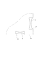
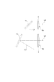
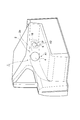
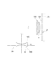
- FIG. 4 is a side view of the lens and reflecting mirror of FIG. 3. It is sectional drawing of a concave lens. It is sectional drawing of a convex lens. It is a perspective view of the left front part in a vehicle interior which shows the modification of the visual recognition apparatus outside a vehicle. It is a figure which shows the example of arrangement
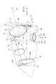
- a vehicle exterior visual recognition device 1 shown in FIGS. 1 to 3 makes it possible to visually recognize the rear outside the vehicle interior and the lower part other than the rear outside the vehicle interior.
- the rear visual recognition optical system A1 and the downward visual recognition optical system A2 are disposed in the housing 2. It is what was contained.
- the outside visual recognition device 1 is provided above the front wheel 7 a on the passenger seat side of the vehicle 7. 1 to 3, the vehicle 7 is a right-hand drive vehicle, and the vehicle exterior visual recognition device 1 is provided above the left front wheel 7 a of the vehicle 7.
- the housing 2 is provided at the left front portion of the vehicle 7, is disposed in the body of the vehicle 7, and opens to the left, and a cover portion that closes the opening of the base portion 2 b and bulges from the left side surface of the vehicle 7. 2a.
- One housing space S is formed inside the housing 2 by the cooperation of the cover portion 2a and the base portion 2b.
- a light incident port 2c is formed rearward, and a light incident port 2d is formed downward.
- Light exits 2e and 2f are formed in the base portion 2b toward the right rear in the vehicle compartment.
- the light exit 2e is located on the outer side of the passenger compartment than the light exit 2f.
- the first concave lens 3 is disposed in the cover portion 2a so as to block the light incident port 2c, and the second concave lens 5 is disposed so as to block the light incident port 2d.
- the center position of the second concave lens 5 and the center position of the front wheel 7a are substantially the same in the front-rear direction.
- a first convex lens 4 is disposed so as to correspond to the light exit port 2e
- a second convex lens 6 is disposed so as to correspond to the light exit port 2f.
- the light exit 2e and the light exit 2f are closed by the transparent panel 20.
- the concave lenses 3 and 5 are, for example, circular biconcave lenses made of acrylic (see FIG. 5).
- the first concave lens 3 transmits light into the accommodation space S from the rear outside the passenger compartment.
- the second concave lens 5 transmits light into the accommodation space S from below the outside of the passenger compartment other than the rear.
- Support members 8 and 9 are fixed to the housing 2 in the housing space S, the outer peripheral portion of the first concave lens 3 is supported by the support member 8, and the outer peripheral portion of the second concave lens 5 is supported by the support member 9. Yes.
- the material of the concave lenses 3 and 5 is not limited to acrylic, and may be other general optical materials, that is, glass, polycarbonate, polyolefin, and the like.
- the convex lenses 4 and 6 are circular plano-convex lenses made of, for example, acrylic.
- the convex surfaces 4a and 6a of the convex lenses 4 and 6 are directed into the passenger compartment so that the driver can visually recognize them (see FIG. 6).
- the convex lenses 4 and 6 transmit light from the accommodation space S to the vehicle interior.
- Support members 10 and 11 are fixed to the housing 2 in the housing space S, the outer peripheral portion of the first convex lens 4 is supported by the support member 10, and the outer peripheral portion of the second convex lens 6 is supported by the support member 11. Yes.
- the material of the convex lenses 4 and 6 is not limited to acrylic, but may be other general optical materials, that is, glass, polycarbonate, polyolefin, or the like.
- one rear-viewing reflection mirror 12 and two lower-viewing reflection mirrors 13 and 14 are arranged.
- the rear-viewing reflection mirror 12 and the lower-viewing reflection mirrors 13 and 14 are flat mirrors in which a reflection film is formed on one surface of a glass disk, for example.
- the rear viewing reflection mirror 12 is disposed on the right front side of the first concave lens 3 and on the left front side of the first convex lens 4, and is positioned on the optical axis L ⁇ b> 1 of the first concave lens 3 and the light of the first convex lens 4. It is located on the axis L2 (see FIG. 4).
- the reflection surface 12a of the rear viewing reflection mirror 12 is directed rearward.
- the light traveling right front along the optical axis L1 is reflected by the reflecting surface 12a and travels right rear along the optical axis L2.
- a support member 15 is fixed to the housing 2 in the housing space S, and the rear viewing reflection mirror 12 is supported by the support member 15 on the back side of the reflection surface 12a.
- the first visually recognizing optical system A ⁇ b> 1 is configured by the first concave lens 3, the rear viewing reflection mirror 12, and the first convex lens 4.
- the first path R1 extends from the first concave lens 3 to the rear viewing reflection mirror 12 toward the right front, and from the rear viewing reflection mirror 12 to the first convex lens 4 toward the right rear.
- the first downward-viewing reflecting mirror 13 is disposed above the second concave lens 5 and is positioned on the optical axis L3 of the second concave lens 5 (see FIG. 4).
- the reflection surface 13a of the first downward-looking reflection mirror 13 is directed to the front right and downward.
- the light that has entered the housing 2 from below along the optical axis L3 is reflected by the reflecting surface 13a and travels forward to the right.
- a support member 16 is fixed to the housing 2 in the housing space S, and the first downward-viewing reflection mirror 13 is supported by the support member 16 on the back side of the reflection surface 13a.
- the second downward-looking visual reflecting mirror 14 is arranged on the right front side of the first downward-looking visual reflecting mirror 13 and on the left front side of the second convex lens 6.
- the second downward-viewing reflecting mirror 14 is located on the light path L4 of the light reflected by the reflecting surface 13a and traveling forward to the right and on the optical axis L5 of the second convex lens 6 (see FIG. 4). ).
- the reflection surface 14a of the second downward-viewing reflection mirror 14 is directed rearward.
- the light traveling forward right along the path L4 is reflected by the reflecting surface 14a and travels right rearward along the optical axis L5.
- a support member 17 is fixed to the housing 2, and the second downward-viewing reflection mirror 14 is supported on the back side of the reflection surface 14 a by the support member 17.
- the second visually recognizing optical system A2 is configured by the second concave lens 5, the downward-viewing reflecting mirrors 13 and 14, and the second convex lens 6.
- the second path R2 reaches the first downward-viewing reflection mirror 13 upward from the concave lens 5, and the second downward-viewing reflection mirror 14 from the first downward-viewing reflection mirror 13 toward the right front. To the second convex lens 6 from the second downward-looking visual reflecting mirror 14 toward the right rear.
- the first path R1 and the second path R2 are not partitioned from each other.
- the path between the rear viewing reflection mirror 12 and the first concave lens 3 in the first path R1 and the path between the lower viewing reflection mirror 13 and the second concave lens 5 in the second path R2 are: Crossed.
- a wide range of images are reduced and captured by the first concave lens 3 from behind the vehicle interior.
- the captured image reaches the first convex lens 4 through the first path R1 in which the rear-viewing reflection mirror 12 is disposed, and is magnified by the first convex lens 4 and visually recognized by the driver.
- a wide-range image is reduced by the second concave lens 5 and taken in from the lower side outside the passenger compartment other than the rear.
- the captured image reaches the second convex lens 6 through the second path R2 in which the downward-viewing reflecting mirrors 13 and 14 are arranged, and is magnified by the second convex lens 6 and visually recognized by the driver.
- the driver can visually recognize the rear side outside the passenger compartment and the lower side outside the passenger compartment outside the passenger compartment with a wide field of view and a size that is easy to visually recognize.
- the rear viewing reflection mirror 12 and the lower viewing reflection mirrors 13 and 14 are disposed in one accommodation space S in a state where the first route R1 and the second route R2 are not partitioned.
- the occupied space on the vehicle can be reduced. Therefore, it is possible to visually recognize the rear outside the passenger compartment and the lower portion outside the passenger compartment other than the rear while reducing the occupied space on the vehicle.
- the first route R1 and the second route R2 intersect in the accommodation space S. Thereby, since the same space is shared by the first route R1 and the second route R2 at the portion where the first route R1 and the second route R2 intersect, the occupied space on the vehicle can be more reliably secured. Can be reduced.
- the image captured from the rear to the front outside the passenger compartment is reflected toward the driver's viewpoint by the single rear-viewing reflection mirror 12, and reaches the driver's viewpoint without being reversed left and right.
- the image captured from the lower side outside the passenger compartment is reflected toward the front by one of the downward-viewing reflecting mirrors 13 so that the front outside the passenger compartment faces upward and the rear outside the passenger compartment faces downward. This is a reflection image that is easy to do.
- the reflected image is reflected toward the driver's viewpoint by another downward-viewing reflection mirror 14, and reaches the driver's viewpoint without any left-right reversal.
- the minimum number of mirrors allows the rear image outside the passenger compartment and the lower part other than the rear outside the passenger compartment. It is possible to reach the driver's viewpoint in a state in which the image is easily visible.
- the front side of the passenger seat Since light from the lower side outside the passenger compartment outside the passenger compartment is light from the front side of the passenger seat, the front side of the passenger seat, which is likely to be a blind spot of the driver, can be viewed.
- the center position of the concave lens 5 and the center position of the front wheel 7a are substantially the same in the front-rear direction, the image around the front wheel 7a is reliably captured from the concave lens 5. Therefore, it is possible to improve the visibility around the front wheel 7a on the passenger seat side, which is likely to be a blind spot of the driver.
- the concave lenses 3 and 5 are biconcave lenses, a larger range of images can be obtained without increasing the curvature of the concave surface than when the concave lenses 3 and 5 are plano-concave lenses, that is, without reducing the radius of curvature of the concave surface. 3 and 5 can be taken in. For this reason, the visual field range can be widened while suppressing distortion of the image outside the passenger compartment.
- the convex lenses 4 and 6 are plano-convex lenses, and the convex surfaces 4a and 6a of the convex lenses 4 and 6 are directed toward the vehicle interior. As a result, even if the amount of deviation between the optical axes L2 and L5 of the convex lenses 4 and 6 and the viewpoint of the driver changes, the magnification of the image captured from the concave lenses 3 and 5 is not easily changed. Can be further improved.
- the relationship among the concave lenses 3 and 5, the convex lenses 4 and 6, the rear viewing reflection mirror 12, and the lower viewing reflection mirrors 13 and 14 will be described in more detail.
- Specific examples of the specifications of the concave lenses 3 and 5, the convex lenses 4 and 6, the rear-viewing reflection mirror 12, and the lower-viewing reflection mirrors 13 and 14 include the following.
- Distance between the principal point of the convex lens 4 and the viewpoint of the driver 1733 mm
- the distance between the intersection of the optical axis L2 of the convex lens 4 and the reflecting surface 12a of the rear viewing reflection mirror 12 and the principal point of the convex lens 4 is 188 mm.
- Focal length of the convex lens 4 outside the passenger compartment 520 mm Effective diameter of convex lens 4: 120 mm Distance between the intersection of the optical axis L1 of the concave lens 3 and the reflecting surface 12a of the reflection mirror 12 for rearward viewing and the principal point of the concave lens 3: 231 mm
- Focal length of the concave lens 3 outside the passenger compartment 78 mm Effective diameter of concave lens 3: 50 mm
- Focal length of the convex lens 6 outside the passenger compartment 918 mm Effective diameter of convex lens 6: 60 mm Path L4 distance: 275.9mm The
- the focal point P1 of the convex lens 4 outside the passenger compartment is located outside the focal point P2 of the concave lens 3 outside the passenger compartment, and the focal point P3 of the convex lens 6 outside the passenger compartment. Is located outside the focal point P4 of the concave lens 5 outside the passenger compartment.
- the focal point P1 outside the passenger compartment of the convex lens 4 means that the parallel light incident on the convex lens 4 from the passenger compartment along the optical axis L2 of the convex lens 4 through the rear-viewing reflection mirror 12 without taking the concave lens 3 into consideration. It is the point which condenses with.
- the focal point P3 outside the passenger compartment of the convex lens 6 refers to the parallel light incident on the convex lens 6 from the passenger compartment along the optical axis L5 of the convex lens 6 through the downward-viewing reflecting mirrors 13 and 14 without considering the concave lens 5. It is a point that collects light outside the passenger compartment.
- the focal points P2 and P4 on the outside of the passenger compartment of the concave lenses 3 and 5 are virtual condensing points of parallel light incident on the concave lenses 3 and 5 along the optical axes L1 and L3 of the concave lenses 3 and 5 from the outside of the passenger compartment.
- the focal point P1 of the convex lens 4 outside the passenger compartment is located outside the focal point P2 of the concave lens 3 outside the passenger compartment, and the focal point P3 of the convex lens 6 outside the passenger compartment is located outside the focal point P4 of the concave lens 5 outside the passenger compartment.
- the outer diameter of the rear-viewing reflection mirror 12 is equal to or larger than the effective diameter of the concave lens 3, and the effective diameter of the convex lens 4 is larger than the outer diameter of the rear-viewing reflection mirror 12. Since the outer diameter of the rear-viewing reflection mirror 12 is greater than or equal to the effective diameter of the concave lens 3, the image captured from the concave lens 3 can be more reliably reflected toward the convex lens 4, thereby ensuring a viewing field range. Can do. Furthermore, since the effective diameter of the convex lens 4 is larger than the outer diameter of the rear viewing reflection mirror 12, the light exit port 2e can be enlarged. The light exit port 2e functions as a display area for displaying an image outside the vehicle interior toward the vehicle interior.
- the outer diameter of the downward-viewing reflecting mirrors 13 and 14 is larger than the effective diameter of the concave lens 5 and larger than the effective diameter of the convex lens 6.
- the outer diameter of the range visible to the driver through the convex lenses 4 and 6 at the position where the concave lenses 3 and 5 are arranged is larger than the outer diameter of the concave lenses 3 and 5. That is, the outer edge of the range visually recognized by the driver through the convex lenses 4 and 6 is located outside the outer edge of the concave lenses 3 and 5. Thereby, since the outer edge of the concave lenses 3 and 5 can be visually recognized through the convex lenses 4 and 6, the front side visibility on the passenger seat side outside the passenger compartment can be further improved.
- the outer diameter and outer edge of the concave lenses 3 and 5 are the outer diameter and outer edge of the surface exposed in the accommodation space S of the concave lenses 3 and 5.
- the outer diameter of the rear-viewing reflection mirror 12 may be larger than the effective diameter of the concave lens 3 and larger than the effective diameter of the convex lens 4. In this case, the rear-viewing reflection mirror 12 can reflect a wider range of images toward the convex lens 4, so that the field of view can be widened and the rear visibility outside the passenger compartment is further improved. Can do.
- the outer diameter of the downward-viewing reflection mirrors 13 and 14 may be greater than or equal to the effective diameter of the concave lens 5, and the effective diameter of the convex lens 6 may be larger than the outer diameter of the downward-viewing reflection mirrors 13 and 14.
- the outer diameter of the downward-viewing reflecting mirrors 13 and 14 is equal to or larger than the effective diameter of the concave lens 5, the image captured from the concave lens 5 can be more reliably reflected toward the convex lens 6. A range can be secured.
- the effective diameter of the convex lens 6 is larger than the outer diameter of the downward-viewing reflection mirrors 13 and 14, the light exit port 2f can be enlarged.
- the light exit port 2f functions as a display area for displaying an image outside the vehicle interior toward the vehicle interior. For this reason, when the light emission port 2f is enlarged, an image outside the vehicle compartment can be displayed toward the vehicle interior in a larger display area, so that the image outside the vehicle compartment can be further enlarged. Therefore, the visibility of the lower side other than the rear outside the passenger compartment can be further improved.
- the outer diameter in the range visually recognized by the driver through the convex lenses 4 and 6 at the position where the concave lenses 3 and 5 are arranged may be smaller than the effective diameter of the concave lenses 3 and 5. That is, the outer edge of the range visually recognized by the driver through the convex lenses 4 and 6 may be located inside the outer edges of the concave lenses 3 and 5. In this case, the image captured from the concave lenses 3 and 5 can be enlarged by using the entire area of the convex lenses 4 and 6, and the front side visibility on the passenger seat side outside the passenger compartment can be further improved.
- the concave lenses 3 and 5 may be plano-concave lenses whose plane is directed outside the passenger compartment. In this case, even if the amount of deviation between the optical axes L1 and L3 of the concave lenses 3 and 5 and the object outside the passenger compartment changes, the magnification of the image of the object captured from the concave lenses 3 and 5 is difficult to change. The front side visibility on the passenger seat side can be further improved.
- the convex lenses 4 and 6 may be biconvex lenses.
- the enlargement ratio of the image outside the passenger compartment can be increased without increasing the curvature of the convex surface, that is, without decreasing the curvature radius of the convex surface, compared to using a plano-convex lens. For this reason, it is possible to increase the enlargement ratio of the image while suppressing distortion of the image outside the passenger compartment, and to further improve the visibility outside the passenger compartment.
- the outer shape of the concave lenses 3 and 5, the convex lenses 4 and 6, the rear-viewing reflection mirror 12, and the lower-viewing reflection mirrors 13 and 14 is not limited to a circular shape.
- the shape can be changed.
- these outer shapes may be elliptical, may be polygonal shapes such as a triangle, a quadrangle, or a pentagon, and the corners of these polygons may be rounded.
- the inner surface of the housing 2 may be blackened by painting or the like.
- the image outside the passenger compartment becomes relatively clear with respect to the image on the inner surface of the housing 2. Therefore, the visibility outside the passenger compartment can be improved.
- a switching device 18 for switching between the two may be provided.
- the switching device 18 is a device that blocks light, such as a mechanical shutter or a liquid crystal shutter. In this case, when it is not necessary for the driver to visually recognize the lower side outside the passenger compartment, the light from the lower side outside the passenger compartment cannot be seen by the switching device 18 so that the driver cannot see the light. Visibility can be further improved by concentrating in the other direction. As shown in FIG.
- the present invention can be used for a vehicle outside visual recognition device.
- SYMBOLS 1 Outside-vehicle visual recognition apparatus, 2 ... Mirror accommodating part, 3 ... 1st concave lens, 4 ... 1st convex lens, 5 ... 2nd concave lens, 6 ... 2nd convex lens, 12 ... Reflection mirror for back visual recognition, 13, 14 ... Reflection mirror for downward viewing, 18, 18A, 18B, 18C, 18D ... Switching device, R1 ... First route, R2 ... Second route, S ... Mirror housing space.
Landscapes
- Engineering & Computer Science (AREA)
- Multimedia (AREA)
- Mechanical Engineering (AREA)
- Rear-View Mirror Devices That Are Mounted On The Exterior Of The Vehicle (AREA)
Description
本発明は、車室外を視認可能にする車外視認装置に関する。
従来、車室外における後方を視認可能にする車外視認装置として、車室外における後方からの光が透過する凹レンズと、運転者が車室内から視認可能な開口部と、凹レンズから開口部に至る経路の途中に配置された凹面鏡と、を備えたものが開示されている(例えば、特許文献1参照)。また、車室外における前輪部近傍を視認可能にする車外視認装置として、車室外における左前輪部からの光を前方側へ屈折させるプリズムと、運転者が車室内から視認可能な覗き窓と、プリズムから覗き窓に至る経路の途中に配置された反射鏡と、を備えたものが開示されている(例えば、特許文献2参照)。
特許文献1に記載された車外視認装置と、特許文献2に記載された車外視認装置との両方を車両に搭載すると、車室外における後方と車室外における後方以外の下方との視認が可能になる。しかしながら、各車外視認装置が車両上の空間の一部を占有することになるため、両方の車外視認装置を搭載するのに必要な空間を一台の車両上に確保することができないおそれがある。
本発明は、車両上の占有空間の縮小を図りつつ、車室外における後方と車室外における後方以外の下方との視認を可能にする車外視認装置を提供することを目的とする。
本発明に係る車外視認装置は、車室外を視認可能にする車外視認装置であって、車室外における後方からの光が透過する第1の凹レンズと、運転者が車室内から視認可能な第1の凸レンズと、第1の凹レンズから第1の凸レンズに至る第1の経路の途中に配置された後方視認用反射ミラーと、車室外における後方以外の下方からの光が透過する第2の凹レンズと、運転者が車室内から視認可能な第2の凸レンズと、第2の凹レンズから第2の凸レンズに至る第2の経路の途中に配置された下方視認用反射ミラーと、を備え、第1の経路と第2の経路とが仕切られない状態で、後方視認用反射ミラーと下方視認用反射ミラーとは一つの空間内に配置されていることを特徴とする。
このような車外視認装置によれば、車室外における後方からは、広範囲の像が第1の凹レンズで縮小されて取り込まれる。取り込まれた像は、後方視認用反射ミラーが配置された第1の経路を経て第1の凸レンズに到達し、第1の凸レンズで拡大されて運転者に視認される。車室外における後方以外の下方からは、広範囲の像が第2の凹レンズで縮小されて取り込まれる。取り込まれた像は、下方視認用反射ミラーが配置された第2の経路を経て第2の凸レンズに到達し、第2の凸レンズで拡大されて運転者に視認される。このようにして、車室外における後方と車室外における後方以外の下方とを広い視野で且つ視認し易い大きさで運転者が視認することができる。更に、第1の経路と第2の経路とが仕切られない状態で、後方視認用反射ミラーと下方視認用反射ミラーとは一つの空間内に配置されているため、車両上の占有空間を縮小することができる。従って、車両上の占有空間の縮小を図りつつ、車室外における後方と車室外における後方以外の下方との視認を可能にすることができる。
第1の経路と第2の経路とは、空間内で交差していてもよい。この場合、第1の経路と第2の経路とが交差する部分において、同じ空間が第1の経路と第2の経路とに共用されるため、車両上の占有空間をより確実に縮小することができる。
車室外における後方以外の下方からの光は、助手席側の前側方からの光であり、後方視認用反射ミラーは一枚からなり、下方視認用反射ミラーは二枚からなり、第1の経路における後方視認用反射ミラーと第1の凹レンズとの間の経路と、第2の経路における下方視認用反射ミラーと第2の凹レンズとの間の経路とは、空間内で交差していてもよい。
この場合、車室外における後方から前方に向かって取り込まれた像を、一枚の後方視認用反射ミラーで運転者の視点に向かって反射させることで、左右反転のない視認し易い像を運転者の視点に到達させることができる。また、車室外における助手席側の前側方から上方に向かって取り込まれた像を、一方の下方視認用反射ミラーで前方に向かって反射させることで、車室外の前方が上を向き車室外の後方が下を向いた視認し易い反射像とすることができる。そして、その反射像を別の下方視認用反射ミラーで運転者の視点に向かって反射させることで、左右反転のない視認し易い像を運転者の視点に到達させることができる。このように、後方視認用反射ミラーを一枚、下方視認用反射ミラーを二枚利用することで、必要最小限の枚数のミラーによって、車室外における後方の像と車室外における助手席側の前側方の像とを視認し易くすることができる。更に、第1の経路における後方視認用反射ミラーと第1の凹レンズとの間の経路と、第2の経路における下方視認用反射ミラーと第2の凹レンズとの間の経路とが交差する部分において、同じ空間が第1の経路と第2の経路とに共用されるため、車両上の占有空間をより確実に縮小することができる。
車室外における後方以外の下方からの光を運転者が視認可能な状態と、車室外における後方以外の下方からの光を運転者が視認不可能な状態とを切り替える切替装置を更に備えていてもよい。この場合、車室外における後方以外の下方を運転者が視認する必要がないときには、切替装置によって車室外における後方以外の下方からの光を運転者が視認不可能な状態とし、運転者の視覚を他の方向に集中させることで更に視認性を向上させることができる。
本発明によれば、車両上の占有空間の縮小を図りつつ、車室外における後方と車室外における後方以外の下方との視認を可能にする車外視認装置を提供することができる。
以下、図面を参照しつつ本発明に係る車外視認装置の好適な実施形態について詳細に説明する。図1~図3に示される車外視認装置1は車室外における後方及び車室外における後方以外の下方を視認可能にするものであり、後方視認光学系A1及び下方視認光学系A2をハウジング2内に収容したものである。車外視認装置1は、車両7の助手席側の前輪7aの上方に設けられている。図1~図3において、車両7は右ハンドル車であり、車外視認装置1は車両7の左の前輪7aの上方に設けられている。
ハウジング2は、車両7の左前部に設けられ、車両7のボディ内に配置され左方に開口したベース部2bと、ベース部2bの開口を塞ぐと共に車両7の左側面から膨出したカバー部2aとを有している。カバー部2aとベース部2bとの協働により、ハウジング2の内側には一つの収容空間Sが形成されている。
カバー部2aには後方に向かって光入射口2cが形成され、下方に向かって光入射口2dが形成されている。ベース部2bには車室内の右後方に向かって光出射口2e,2fが形成されている。光出射口2eは、光出射口2fよりも車室外側に位置している。図3に示されるように、カバー部2a内には光入射口2cを塞ぐように第1の凹レンズ3が配置され、光入射口2dを塞ぐように第2の凹レンズ5が配置されている。第2の凹レンズ5の中心位置と前輪7aの中心位置とは前後方向で略同じとなっている。ベース部2b内には光出射口2eに対応するように第1の凸レンズ4が配置され、光出射口2fに対応するように第2の凸レンズ6が配置されている。光出射口2e及び光出射口2fは、透明パネル20によって塞がれている。
凹レンズ3,5は、例えばアクリルからなる円形の両凹レンズである(図5参照)。第1の凹レンズ3は、車室外における後方から収容空間S内に光を透過させる。第2の凹レンズ5は、車室外における後方以外の下方から収容空間S内に光を透過させる。収容空間S内においてハウジング2には支持部材8,9が固定され、第1の凹レンズ3の外周部分は支持部材8によって支持され、第2の凹レンズ5の外周部分は支持部材9によって支持されている。なお、凹レンズ3,5の材料はアクリルに限定されるものではなく、他の一般的な光学材料、すなわちガラス、ポリカーボネート、ポリオレフィン等であってもよい。
凸レンズ4,6は、例えばアクリルからなる円形の平凸レンズである。凸レンズ4,6の凸面4a,6aは、運転者が視認できるように車室内に向けられている(図6参照)。凸レンズ4,6は、収容空間S内から車室内に光を透過させる。収容空間S内においてハウジング2には支持部材10,11が固定され、第1の凸レンズ4の外周部分は支持部材10によって支持され、第2の凸レンズ6の外周部分は支持部材11によって支持されている。なお、凸レンズ4,6の材料はアクリルに限定されるものではなく、他の一般的な光学材料、すなわちガラス、ポリカーボネート、ポリオレフィン等であってもよい。
収容空間S内には、一枚の後方視認用反射ミラー12と二枚の下方視認用反射ミラー13,14が配置されている。後方視認用反射ミラー12及び下方視認用反射ミラー13,14は、例えばガラスの円板の片面に反射膜が形成された平面鏡である。
後方視認用反射ミラー12は、第1の凹レンズ3の右前方且つ第1の凸レンズ4の左前方に配置され、第1の凹レンズ3の光軸L1上に位置すると共に第1の凸レンズ4の光軸L2上に位置している(図4参照)。後方視認用反射ミラー12の反射面12aは後方に向けられている。光軸L1に沿って右前方に進む光は、反射面12aで反射し、光軸L2に沿って右後方に進む。収容空間S内においてハウジング2には支持部材15が固定され、後方視認用反射ミラー12は支持部材15によって反射面12aの裏側で支持されている。
後方視認用反射ミラー12が配置されていることにより、車室外における後方から第1の凹レンズ3を透過した光は第1の経路R1を通って第1の凸レンズ4に到達し、第1の凸レンズ4を透過して運転者に視認される。すなわち第1の凹レンズ3と後方視認用反射ミラー12と第1の凸レンズ4とによって後方視認光学系A1が構成されている。第1の経路R1は、第1の凹レンズ3から右前方に向かっての後方視認用反射ミラー12に至り、後方視認用反射ミラー12から右後方に向かって第1の凸レンズ4に至っている。
第1の下方視認用反射ミラー13は、第2の凹レンズ5の上方に配置され、第2の凹レンズ5の光軸L3上に位置している(図4参照)。第1の下方視認用反射ミラー13の反射面13aは右前方且つ下方に向けられている。光軸L3に沿って下方からハウジング2内に入射した光は、反射面13aで反射して右前方に進む。収容空間S内においてハウジング2には支持部材16が固定され、第1の下方視認用反射ミラー13は支持部材16によって反射面13aの裏側で支持されている。
第2の下方視認用反射ミラー14は、第1の下方視認用反射ミラー13の右前方且つ第2の凸レンズ6の左前方に配置されている。第2の下方視認用反射ミラー14は、反射面13aで反射して右前方に進む光の経路L4上に位置すると共に第2の凸レンズ6の光軸L5上に位置している(図4参照)。第2の下方視認用反射ミラー14の反射面14aは後方に向けられている。経路L4に沿って右前方に進む光は、反射面14aで反射し、光軸L5に沿って右後方に進む。収容空間Sにおいてハウジング2には支持部材17が固定され、第2の下方視認用反射ミラー14は支持部材17によって反射面14aの裏側で支持されている。
下方視認用反射ミラー13,14が配置されていることにより、車室外における後方以外の下方から第2の凹レンズ5を透過した光は第2の経路R2を通って第2の凸レンズ6に到達し、第2の凸レンズ6を透過して運転者に視認される。すなわち第2の凹レンズ5と下方方視認用反射ミラー13,14と第2の凸レンズ6とによって下方視認光学系A2が構成されている。第2の経路R2は、凹レンズ5から上方に向かって第1の下方視認用反射ミラー13に至り、第1の下方視認用反射ミラー13から右前方に向かって第2の下方視認用反射ミラー14に至り、第2の下方視認用反射ミラー14から右後方に向かって第2の凸レンズ6に至っている。
後方視認用反射ミラー12と下方視認用反射ミラー13,14とが一つの収容空間S内に配置されていることから、第1の経路R1と第2の経路R2とは互いに仕切られていない。第1の経路R1における後方視認用反射ミラー12と第1の凹レンズ3との間の経路と、第2の経路R2における下方視認用反射ミラー13と第2の凹レンズ5との間の経路とは交差している。
このような車外視認装置1によれば、車室外における後方からは、広範囲の像が第1の凹レンズ3で縮小されて取り込まれる。取り込まれた像は、後方視認用反射ミラー12が配置された第1の経路R1を経て第1の凸レンズ4に到達し、第1の凸レンズ4で拡大されて運転者に視認される。車室外における後方以外の下方からは、広範囲の像が第2の凹レンズ5で縮小されて取り込まれる。取り込まれた像は、下方視認用反射ミラー13,14が配置された第2の経路R2を経て第2の凸レンズ6に到達し、第2の凸レンズ6で拡大されて運転者に視認される。このようにして、車室外における後方と車室外における後方以外の下方とを広い視野で且つ視認し易い大きさで運転者が視認することができる。更に、第1の経路R1と第2の経路R2とが仕切られない状態で、後方視認用反射ミラー12と下方視認用反射ミラー13,14とは一つの収容空間S内に配置されているため、車両上の占有空間を縮小することができる。従って、車両上の占有空間の縮小を図りつつ、車室外における後方と車室外における後方以外の下方との視認を可能にすることができる。
第1の経路R1と第2の経路R2とは、収容空間S内で交差している。これにより、第1の経路R1と第2の経路R2とが交差する部分において、同じ空間が第1の経路R1と第2の経路R2とに共用されるため、車両上の占有空間をより確実に縮小することができる。
車室外における後方から前方に向かって取り込まれた像は、一枚の後方視認用反射ミラー12で運転者の視点に向かって反射し、左右反転のない状態で運転者の視点に到達する。車室外における後方以外の下方から取り込まれた像は、一方の下方視認用反射ミラー13で前方に向かって反射することで、車室外の前方が上を向き車室外の後方が下を向いた視認し易い反射像となる。そして、その反射像は、別の下方視認用反射ミラー14で運転者の視点に向かって反射し、左右反転のない状態で運転者の視点に到達する。このように、後方視認用反射ミラーを一枚、下方視認用反射ミラーを二枚利用することで、必要最小限の枚数のミラーによって、車室外における後方の像と車室外における後方以外の下方の像とを視認し易い状態で運転者の視点に到達させることができる。
車室外における後方以外の下方からの光は、助手席側の前側方からの光であるため、運転者の死角となりやすい助手席側の前側方の視認を可能にすることができる。特に、凹レンズ5の中心位置と前輪7aの中心位置とは前後方向で略同じとなっているため、前輪7aの周囲の像が確実に凹レンズ5から取り込まれる。従って、運転者の死角となりやすい助手席側の前輪7aの周囲の視認性を向上させることができる。
凹レンズ3,5は両凹レンズであることから、凹レンズ3,5が平凹レンズであるのに比べ凹面の曲率を大きくすることなく、すなわち凹面の曲率半径を小さくすることなく、より広範囲の像を凹レンズ3,5から取り込むことができる。このため、車室外の像の歪みを抑制しながら視野範囲を広くすることができる。
凸レンズ4,6は平凸レンズであり、凸レンズ4,6の凸面4a,6aは車室内に向けられている。これにより、凸レンズ4,6の光軸L2,L5と運転者の視点とのずれ量が変わっても、凹レンズ3,5から取り込まれた像の拡大率は変わり難くなるので、車室外の視認性を更に向上させることができる。
次に、凹レンズ3,5と凸レンズ4,6と後方視認用反射ミラー12と下方視認用反射ミラー13,14との関係について更に詳細に説明する。凹レンズ3,5、凸レンズ4,6、後方視認用反射ミラー12、下方視認用反射ミラー13,14の仕様の具体例として、次のようなものが挙げられる。
凸レンズ4の主点と運転者の視点との距離:1733mm
凸レンズ4の光軸L2と後方視認用反射ミラー12の反射面12aとの交点と、凸レンズ4の主点との距離:188mm
凸レンズ4の車室外側の焦点距離:520mm
凸レンズ4の有効径:120mm
凹レンズ3の光軸L1と後方視認用反射ミラー12の反射面12aとの交点と、凹レンズ3の主点との距離:231mm
凹レンズ3の車室外側の焦点距離:78mm
凹レンズ3の有効径:50mm
凹レンズ3の外径:54mm
後方視認用反射ミラー12の外径:95mm
凸レンズ6の主点と運転者の視点との距離:1736mm
凸レンズ6の光軸L5と下方視認用反射ミラー14の反射面14aとの交点と、凸レンズ6の主点との距離:84mm
凸レンズ6の車室外側の焦点距離:918mm
凸レンズ6の有効径:60mm
経路L4の距離:275.9mm
凹レンズ5の光軸L3と下方視認用反射ミラー13の反射面13aとの交点と、凹レンズ5の主点との距離:105mm
凹レンズ5の車室外側の焦点距離:51mm
凹レンズ5の有効径:46mm
凹レンズ5の外径:50mm
下方視認用反射ミラー13,14の外径:74mm
凸レンズ4の主点と運転者の視点との距離:1733mm
凸レンズ4の光軸L2と後方視認用反射ミラー12の反射面12aとの交点と、凸レンズ4の主点との距離:188mm
凸レンズ4の車室外側の焦点距離:520mm
凸レンズ4の有効径:120mm
凹レンズ3の光軸L1と後方視認用反射ミラー12の反射面12aとの交点と、凹レンズ3の主点との距離:231mm
凹レンズ3の車室外側の焦点距離:78mm
凹レンズ3の有効径:50mm
凹レンズ3の外径:54mm
後方視認用反射ミラー12の外径:95mm
凸レンズ6の主点と運転者の視点との距離:1736mm
凸レンズ6の光軸L5と下方視認用反射ミラー14の反射面14aとの交点と、凸レンズ6の主点との距離:84mm
凸レンズ6の車室外側の焦点距離:918mm
凸レンズ6の有効径:60mm
経路L4の距離:275.9mm
凹レンズ5の光軸L3と下方視認用反射ミラー13の反射面13aとの交点と、凹レンズ5の主点との距離:105mm
凹レンズ5の車室外側の焦点距離:51mm
凹レンズ5の有効径:46mm
凹レンズ5の外径:50mm
下方視認用反射ミラー13,14の外径:74mm
この仕様では、図3及び図4に示されるように、凸レンズ4の車室外側の焦点P1は凹レンズ3の車室外側の焦点P2よりも外側に位置し、凸レンズ6の車室外側の焦点P3は凹レンズ5の車室外側の焦点P4よりも外側に位置している。凸レンズ4の車室外側の焦点P1とは、凹レンズ3を考慮しない状態で、凸レンズ4の光軸L2に沿って車室内から凸レンズ4に入射した平行光が後方視認用反射ミラー12を経て車室外で集光する点である。凸レンズ6の車室外側の焦点P3とは、凹レンズ5を考慮しない状態で、凸レンズ6の光軸L5に沿って車室内から凸レンズ6に入射した平行光が下方視認用反射ミラー13,14を経て車室外で集光する点である。凹レンズ3,5の車室外側の焦点P2,P4とは、凹レンズ3,5の光軸L1,L3に沿い車室外から凹レンズ3,5に入射した平行光の仮想集光点である。凸レンズ4の車室外側の焦点P1は凹レンズ3の車室外側の焦点P2よりも外側に位置し、凸レンズ6の車室外側の焦点P3は凹レンズ5の車室外側の焦点P4よりも外側に位置していることにより、凹レンズ3,5から取り込まれた車室外の像をより確実に拡大して運転者に視認させることができる。
また、後方視認用反射ミラー12の外径は凹レンズ3の有効径以上であり、凸レンズ4の有効径は後方視認用反射ミラー12の外径より大きい。後方視認用反射ミラー12の外径は凹レンズ3の有効径以上であることにより、凹レンズ3から取り込まれた像をより確実に凸レンズ4に向かって反射させることができるので、視野範囲を確保することができる。更に、凸レンズ4の有効径が後方視認用反射ミラー12の外径よりも大きいことにより、光出射口2eを大きくすることができる。光出射口2eは、車室内に向けて車室外の像を表示する表示領域として機能する。このため、光出射口2eを大きくすると、車室外の像をより大きい表示領域で車室内に向かって表示することができるので、車室外の像をより拡大することができる。従って、車室外における後方の視認性をより向上させることができる。
また、下方視認用反射ミラー13,14の外径は凹レンズ5の有効径よりも大きく且つ凸レンズ6の有効径よりも大きい。これにより、下方視認用反射ミラー13,14によって、より広範囲の像を凸レンズ6に向かって反射させることができるので、視野範囲をより広くすることができ、車室外における後方以外の下方の視認性をより向上させることができる。
また、凹レンズ3,5が配置されている位置において、凸レンズ4,6を通して運転者に視認される範囲の外径は凹レンズ3,5の外径よりも大きい。すなわち、凸レンズ4,6を通して運転者に視認される範囲の外縁は、凹レンズ3,5の外縁よりも外側に位置している。これにより、凸レンズ4,6を通して凹レンズ3,5の外縁を視認することができるので、車室外における助手席側の前側方の視認性をより向上させることができる。凹レンズ3,5の外径及び外縁とは、凹レンズ3,5の収容空間S内に露出する面の外径及び外縁である。
なお、後方視認用反射ミラー12の外径を凹レンズ3の有効径よりも大きく且つ凸レンズ4の有効径よりも大きくしてもよい。この場合、後方視認用反射ミラー12によって、より広範囲の像を凸レンズ4に向かって反射させることができるので、視野範囲をより広くすることができ、車室外における後方の視認性をより向上させることができる。
また、下方視認用反射ミラー13,14の外径を凹レンズ5の有効径以上とし、凸レンズ6の有効径を下方視認用反射ミラー13,14の外径より大きくしてもよい。この場合、下方視認用反射ミラー13,14の外径は凹レンズ5の有効径以上であることにより、凹レンズ5から取り込まれた像をより確実に凸レンズ6に向かって反射させることができるので、視野範囲を確保することができる。更に、凸レンズ6の有効径が下方視認用反射ミラー13,14の外径よりも大きいことにより、光出射口2fを大きくすることができる。光出射口2fは、車室内に向けて車室外の像を表示する表示領域として機能する。このため、光出射口2fを大きくすると、車室外の像をより大きい表示領域で車室内に向かって表示することができるので、車室外の像をより拡大することができる。従って、車室外における後方以外の下方の視認性をより向上させることができる。
また、凹レンズ3,5が配置されている位置において、凸レンズ4,6を通して運転者に視認される範囲の外径は凹レンズ3,5の有効径より小さくてもよい。すなわち、凸レンズ4,6を通して運転者に視認される範囲の外縁は、凹レンズ3,5の外縁よりも内側に位置していてもよい。この場合、凹レンズ3,5から取り込まれた像を凸レンズ4,6の全域を活用して拡大し、車室外における助手席側の前側方の視認性をより向上させることができる。
以上、本発明の好適な実施形態について説明してきたが、本発明は必ずしも上述した実施形態に限定されるものではなく、その要旨を逸脱しない範囲で様々な変更が可能である。
例えば、凹レンズ3,5は平面が車室外に向けられた平凹レンズであってもよい。この場合、凹レンズ3,5の光軸L1,L3と車室外の物体とのずれ量が変わっても、凹レンズ3,5から取り込まれたその物体の像の拡大率は変わり難くなるので、車室外における助手席側の前側方の視認性をより向上させることができる。
また、凸レンズ4,6は両凸レンズであってもよい。この場合、平凸レンズを用いるのに比べ、凸面の曲率を大きくすることなく、すなわち凸面の曲率半径を小さくすることなく車室外の像の拡大率を高くすることができる。このため、車室外の像の歪みを抑制しながら像の拡大率を高くすることができ、車室外の視認性をより向上させることができる。
また、凹レンズ3,5、凸レンズ4,6、後方視認用反射ミラー12、下方視認用反射ミラー13,14の外形は円形に限られず、設置スペースや視認性を考慮して、これらの外形を様々な形状に変えることができる。例えば、これらの外形を楕円形としてもよく、三角形、四角形、又は五角形等の多角形状としてもよく、これらの多角形状の角部を丸めてもよい。
また、ハウジング2の内面を塗装等によって黒色にしてもよい。この場合、ハウジング2の内面の像に対して車室外の像が相対的に明瞭となる。従って、車室外の視認性をより良好にすることができる。
また、図7に示されるように、車室外における後方以外の下方からの光を運転者が視認可能な状態と、車室外における後方以外の下方からの光を運転者が視認不可能な状態とを切り替える切替装置18を設けてもよい。切替装置18は、例えばメカニカルシャッターや液晶シャッター等、光を遮断する装置である。この場合、車室外における後方以外の下方を運転者が視認する必要がないときには、切替装置18によって車室外における後方以外の下方からの光を運転者が視認不可能な状態とし、運転者の視覚を他の方向に集中させることで更に視認性を向上させることができる。図8に示されるように、切替装置18の例として、凸レンズ6の外側に配置された切替装置18A、凸レンズ6の内側に配置された切替装置18B、凹レンズ5の内側に配置された切替装置18C、凹レンズ5の外側に配置された切替装置18D等が挙げられる。
本発明は、車外視認装置に利用できる。
1…車外視認装置、2…ミラー収容部、3…第1の凹レンズ、4…第1の凸レンズ、5…第2の凹レンズ、6…第2の凸レンズ、12…後方視認用反射ミラー、13,14…下方視認用反射ミラー、18,18A,18B,18C,18D…切替装置、R1…第1の経路、R2…第2の経路、S…ミラー収容空間。
Claims (4)
- 車室外を視認可能にする車外視認装置であって、
車室外における後方からの光が透過する第1の凹レンズと、
運転者が車室内から視認可能な第1の凸レンズと、
前記第1の凹レンズから前記第1の凸レンズに至る第1の経路の途中に配置された後方視認用反射ミラーと、
車室外における後方以外の下方からの光が透過する第2の凹レンズと、
運転者が車室内から視認可能な第2の凸レンズと、
前記第2の凹レンズから前記第2の凸レンズに至る第2の経路の途中に配置された下方視認用反射ミラーと、を備え、
前記第1の経路と前記第2の経路とが仕切られない状態で、前記後方視認用反射ミラーと前記下方視認用反射ミラーとは一つの空間内に配置されていることを特徴とする車外視認装置。 - 前記第1の経路と前記第2の経路とは、前記空間内で交差していることを特徴とする請求項1記載の車外視認装置。
- 前記車室外における後方以外の下方からの光は、助手席側の前側方からの光であり、
前記後方視認用反射ミラーは一枚からなり、前記下方視認用反射ミラーは二枚からなり、
前記第1の経路における前記後方視認用反射ミラーと前記第1の凹レンズとの間の経路と、前記第2の経路における前記下方視認用反射ミラーと前記第2の凹レンズとの間の経路とは、前記空間内で交差していることを特徴とする請求項1記載の車外視認装置。 - 前記車室外における後方以外の下方からの光を運転者が視認可能な状態と、前記車室外における後方以外の下方からの光を運転者が視認不可能な状態とを切り替える切替装置を更に備えることを特徴とする請求項1~3のいずれか一項記載の車外視認装置。
Applications Claiming Priority (2)
| Application Number | Priority Date | Filing Date | Title |
|---|---|---|---|
| JP2012010327A JP2013147191A (ja) | 2012-01-20 | 2012-01-20 | 車外視認装置 |
| JP2012-010327 | 2012-01-20 |
Publications (1)
| Publication Number | Publication Date |
|---|---|
| WO2013108682A1 true WO2013108682A1 (ja) | 2013-07-25 |
Family
ID=48799109
Family Applications (1)
| Application Number | Title | Priority Date | Filing Date |
|---|---|---|---|
| PCT/JP2013/050200 Ceased WO2013108682A1 (ja) | 2012-01-20 | 2013-01-09 | 車外視認装置 |
Country Status (2)
| Country | Link |
|---|---|
| JP (1) | JP2013147191A (ja) |
| WO (1) | WO2013108682A1 (ja) |
Citations (6)
| Publication number | Priority date | Publication date | Assignee | Title |
|---|---|---|---|---|
| FR1079274A (fr) * | 1953-04-30 | 1954-11-29 | Dispositif rétroviseur, notamment pour automobiles et applications analogues | |
| JPS5033438U (ja) * | 1973-07-23 | 1975-04-11 | ||
| JPH05301540A (ja) * | 1992-04-28 | 1993-11-16 | Tokai Rika Co Ltd | 自動車の補助ミラー |
| EP0901937A1 (fr) * | 1997-09-10 | 1999-03-17 | Automobiles Peugeot | Rétroviseur pour véhicules automobiles |
| JP2001187547A (ja) * | 1999-12-02 | 2001-07-10 | Ford Global Technol Inc | 車両用画像取得及び表示組立体 |
| FR2820097A1 (fr) * | 2001-01-30 | 2002-08-02 | Peugeot Citroen Automobiles Sa | Retrovisseur a encombrement reduit a faible surface frontale |
-
2012
- 2012-01-20 JP JP2012010327A patent/JP2013147191A/ja active Pending
-
2013
- 2013-01-09 WO PCT/JP2013/050200 patent/WO2013108682A1/ja not_active Ceased
Patent Citations (6)
| Publication number | Priority date | Publication date | Assignee | Title |
|---|---|---|---|---|
| FR1079274A (fr) * | 1953-04-30 | 1954-11-29 | Dispositif rétroviseur, notamment pour automobiles et applications analogues | |
| JPS5033438U (ja) * | 1973-07-23 | 1975-04-11 | ||
| JPH05301540A (ja) * | 1992-04-28 | 1993-11-16 | Tokai Rika Co Ltd | 自動車の補助ミラー |
| EP0901937A1 (fr) * | 1997-09-10 | 1999-03-17 | Automobiles Peugeot | Rétroviseur pour véhicules automobiles |
| JP2001187547A (ja) * | 1999-12-02 | 2001-07-10 | Ford Global Technol Inc | 車両用画像取得及び表示組立体 |
| FR2820097A1 (fr) * | 2001-01-30 | 2002-08-02 | Peugeot Citroen Automobiles Sa | Retrovisseur a encombrement reduit a faible surface frontale |
Also Published As
| Publication number | Publication date |
|---|---|
| JP2013147191A (ja) | 2013-08-01 |
Similar Documents
| Publication | Publication Date | Title |
|---|---|---|
| JP6650584B2 (ja) | ヘッドアップディスプレイおよびヘッドアップディスプレイを搭載した移動体 | |
| US11448877B2 (en) | Projection optical system and head-up display | |
| JP6561323B2 (ja) | ヘッドアップディスプレイ | |
| JP6697750B2 (ja) | 車両用表示システム、電子ミラーシステム及びそれを備える移動体 | |
| JP7162273B2 (ja) | ヘッドアップディスプレイおよびヘッドアップディスプレイを搭載した移動体 | |
| JP6940825B2 (ja) | 変倍投影光学系及び画像表示装置 | |
| WO2017061039A1 (ja) | 投影光学系及びヘッドアップディスプレイ装置 | |
| JP6510578B2 (ja) | ヘッドアップディスプレイ装置 | |
| TW201316034A (zh) | 多光路抬頭顯像裝置 | |
| WO2019106951A1 (ja) | 車両用表示装置および車両用表示システム | |
| WO2016038767A1 (ja) | ヘッドアップディスプレイ及び移動体 | |
| CN103048786A (zh) | 多光路抬头显像装置 | |
| WO2017061016A1 (ja) | 情報表示装置 | |
| JP2009115908A (ja) | ミラー光学系及びヘッドアップディスプレイ装置 | |
| JP6830182B2 (ja) | 画像投写装置 | |
| WO2019116730A1 (ja) | ヘッドアップディスプレイおよびヘッドアップディスプレイを搭載した移動体 | |
| JP5533750B2 (ja) | 車載表示装置 | |
| JP2010224016A (ja) | 画像表示装置 | |
| CN103534124A (zh) | 车辆用显示装置 | |
| WO2018186149A1 (ja) | ヘッドアップディスプレイシステム、およびヘッドアップディスプレイシステムを備える移動体 | |
| JP2013052859A (ja) | 車両用アウターミラー | |
| JP6335524B2 (ja) | ヘッドアップディスプレイ装置 | |
| JPWO2018110336A1 (ja) | ヘッドアップディスプレイ装置 | |
| JP2013147191A (ja) | 車外視認装置 | |
| JP2014226951A (ja) | 車両用表示装置 |
Legal Events
| Date | Code | Title | Description |
|---|---|---|---|
| 121 | Ep: the epo has been informed by wipo that ep was designated in this application |
Ref document number: 13738960 Country of ref document: EP Kind code of ref document: A1 |
|
| NENP | Non-entry into the national phase |
Ref country code: DE |
|
| 122 | Ep: pct application non-entry in european phase |
Ref document number: 13738960 Country of ref document: EP Kind code of ref document: A1 |