WO2013102989A1 - 2次元放射線表示装置および2次元放射線表示方法 - Google Patents
2次元放射線表示装置および2次元放射線表示方法 Download PDFInfo
- Publication number
- WO2013102989A1 WO2013102989A1 PCT/JP2012/008326 JP2012008326W WO2013102989A1 WO 2013102989 A1 WO2013102989 A1 WO 2013102989A1 JP 2012008326 W JP2012008326 W JP 2012008326W WO 2013102989 A1 WO2013102989 A1 WO 2013102989A1
- Authority
- WO
- WIPO (PCT)
- Prior art keywords
- data
- radiation
- dimensional
- dimensional radiation
- processing unit
- Prior art date
Links
- 230000005855 radiation Effects 0.000 title claims abstract description 302
- 238000000034 method Methods 0.000 title claims description 31
- 238000012545 processing Methods 0.000 claims abstract description 151
- 230000010354 integration Effects 0.000 claims abstract description 89
- 238000003786 synthesis reaction Methods 0.000 claims abstract description 32
- 230000015572 biosynthetic process Effects 0.000 claims abstract description 30
- 238000001514 detection method Methods 0.000 claims description 43
- 230000008569 process Effects 0.000 claims description 10
- 230000005251 gamma ray Effects 0.000 description 29
- 238000010586 diagram Methods 0.000 description 9
- 230000035945 sensitivity Effects 0.000 description 8
- 238000005202 decontamination Methods 0.000 description 7
- 230000003588 decontaminative effect Effects 0.000 description 7
- 239000000941 radioactive substance Substances 0.000 description 7
- 238000003384 imaging method Methods 0.000 description 4
- 230000002194 synthesizing effect Effects 0.000 description 4
- 230000006870 function Effects 0.000 description 3
- 239000012857 radioactive material Substances 0.000 description 3
- 230000006798 recombination Effects 0.000 description 3
- 238000005215 recombination Methods 0.000 description 3
- 230000011218 segmentation Effects 0.000 description 3
- 229910004613 CdTe Inorganic materials 0.000 description 2
- 238000006243 chemical reaction Methods 0.000 description 2
- 241001270131 Agaricus moelleri Species 0.000 description 1
- 238000003491 array Methods 0.000 description 1
- 230000008859 change Effects 0.000 description 1
- 238000012790 confirmation Methods 0.000 description 1
- 238000010276 construction Methods 0.000 description 1
- 238000011161 development Methods 0.000 description 1
- 230000018109 developmental process Effects 0.000 description 1
- 238000002474 experimental method Methods 0.000 description 1
- 230000006872 improvement Effects 0.000 description 1
- 238000012986 modification Methods 0.000 description 1
- 230000004048 modification Effects 0.000 description 1
- 238000005192 partition Methods 0.000 description 1
- 239000004065 semiconductor Substances 0.000 description 1
Images


Classifications
-
- G—PHYSICS
- G01—MEASURING; TESTING
- G01V—GEOPHYSICS; GRAVITATIONAL MEASUREMENTS; DETECTING MASSES OR OBJECTS; TAGS
- G01V5/00—Prospecting or detecting by the use of ionising radiation, e.g. of natural or induced radioactivity
- G01V5/20—Detecting prohibited goods, e.g. weapons, explosives, hazardous substances, contraband or smuggled objects
- G01V5/281—Detecting prohibited goods, e.g. weapons, explosives, hazardous substances, contraband or smuggled objects detecting special nuclear material [SNM], e.g. Uranium-235, Uranium-233 or Plutonium-239
-
- G—PHYSICS
- G01—MEASURING; TESTING
- G01T—MEASUREMENT OF NUCLEAR OR X-RADIATION
- G01T1/00—Measuring X-radiation, gamma radiation, corpuscular radiation, or cosmic radiation
- G01T1/16—Measuring radiation intensity
- G01T1/169—Exploration, location of contaminated surface areas
-
- G—PHYSICS
- G01—MEASURING; TESTING
- G01T—MEASUREMENT OF NUCLEAR OR X-RADIATION
- G01T1/00—Measuring X-radiation, gamma radiation, corpuscular radiation, or cosmic radiation
- G01T1/16—Measuring radiation intensity
- G01T1/17—Circuit arrangements not adapted to a particular type of detector
-
- G—PHYSICS
- G06—COMPUTING; CALCULATING OR COUNTING
- G06T—IMAGE DATA PROCESSING OR GENERATION, IN GENERAL
- G06T11/00—2D [Two Dimensional] image generation
- G06T11/001—Texturing; Colouring; Generation of texture or colour
-
- G—PHYSICS
- G06—COMPUTING; CALCULATING OR COUNTING
- G06T—IMAGE DATA PROCESSING OR GENERATION, IN GENERAL
- G06T11/00—2D [Two Dimensional] image generation
- G06T11/20—Drawing from basic elements, e.g. lines or circles
- G06T11/206—Drawing of charts or graphs
Definitions
- Embodiments of the present invention relate to a two-dimensional radiation display device and a two-dimensional radiation display method.
- the two-dimensional radiation display device is a device that displays the direction of the radiation source in a two-dimensional arrangement and the intensity on the screen in color and brightness.
- a CCD Charge-Coupled Device
- the radiation detectors are arranged in a two-dimensional array, and the outputs (pulse count values, current values, voltage values, etc.) of the individual radiation detectors are arranged two-dimensionally. And a scintillator that emits light by the incidence of radiation is photographed with a CCD camera or the like.
- a ⁇ -ray radioactivity distribution imaging method for imaging a radioactivity distribution by detecting the intensity of ⁇ -rays a plurality of times by rotating the ⁇ -ray detector array about the direction of incidence of ⁇ -rays as a rotation axis, the least square method It is disclosed that the relative value of the radioactivity intensity and the sensitivity of the ⁇ -ray detector that minimizes the predetermined formula is obtained by fitting calculation using the method, the fitting calculation of the predetermined formula is repeated, and the radioactivity distribution of the radioactive substance is obtained. ing.
- a gamma ray imaging apparatus and the like are disclosed.
- the 2D radiation display device that can easily recognize the contaminated part is effective as a tool for improving the efficiency of the decontamination work.
- the decontamination work can be efficiently performed by decontaminating only the contaminated part with the radioactive material. Furthermore, the decontamination confirmation work of the contaminated part after decontamination is the same.
- the problem to be solved by the embodiment of the present invention is to provide a two-dimensional radiation display device and a two-dimensional radiation display method that can recognize a contaminated portion due to radioactive substances in a short time.
- a two-dimensional radiation display device receives radiation detection signals from a plurality of two-dimensionally arranged radiation detectors, and based on the radiation detection signals.
- This is a two-dimensional radiation display device capable of outputting display data for displaying a radiation distribution.
- the two-dimensional radiation display device includes a data acquisition unit that converts the radiation detection signals detected a plurality of times from the plurality of radiation detectors into two-dimensional radiation data corresponding to the arrayed positions, and the data acquisition unit.
- a data division processing unit that divides the converted two-dimensional radiation data for each region of the section that specifies a direction, and the two-dimensional data that is divided by the data division processing unit for each region of the section that specifies the direction.
- An integration processing unit that integrates radiation data; a data synthesis processing unit that synthesizes two-dimensional data indicating a radiation distribution based on an integration value for each region of the section specifying the direction integrated by the integration processing unit; An image output unit for outputting the two-dimensional data synthesized by the data synthesis processing unit as display data in accordance with a predetermined display format.
- the two-dimensional radiation display device of another embodiment receives radiation detection signals from a plurality of two-dimensionally arrayed radiation detectors and displays a radiation distribution based on the radiation detection signals.
- a two-dimensional radiation display device capable of outputting the display data.
- the two-dimensional radiation display device includes a data acquisition unit that converts the radiation detection signals detected a plurality of times from the plurality of radiation detectors into two-dimensional radiation data corresponding to the arrayed positions, and the data acquisition unit.
- the converted two-dimensional radiation data is divided by an area determination data division processing unit that divides more than the determination value according to a reference value for dividing the area, and the area determination data division processing unit.
- the two-dimensional data indicating the radiation distribution is synthesized.
- a data synthesis processing unit that outputs the two-dimensional data synthesized by the data synthesis processing unit as display data according to a predetermined display format
- An image output unit wherein the region determination data division processing unit determines the determination value based on the accuracy of the integral value or a statistically significant value, and uses the determined determination value as a reference for the two-dimensional radiation It is characterized by dividing data.
- a two-dimensional radiation display method receives a radiation detection signal from a plurality of two-dimensionally arrayed radiation detectors, and based on the radiation detection signal.
- This is a two-dimensional radiation display method of a two-dimensional radiation display device capable of outputting display data for displaying a radiation distribution.
- the data acquisition means of the two-dimensional radiation display device converts the radiation detection signals detected a plurality of times from the plurality of radiation detectors into two-dimensional radiation data corresponding to the arrayed positions.
- an integration processing unit that integrates the two-dimensional radiation data for each region of the section that specifies the direction divided in the data division processing step, and an integration processing step of the two-dimensional radiation display device;
- the data synthesis processing means of the radiation display device identifies the direction integrated in the integration processing step.
- a data synthesis processing step for synthesizing two-dimensional data indicating a radiation distribution based on an integral value for each area of the segment, and an image output means of the two-dimensional radiation display device, wherein the data synthesis processing step And an image output step of outputting the two-dimensional data as display data according to a predetermined display format.
- the two-dimensional radiation display method receives a radiation detection signal from a plurality of two-dimensionally arrayed radiation detectors and displays a radiation distribution based on the radiation detection signal.
- a two-dimensional radiation display method of a two-dimensional radiation display device capable of outputting the display data.
- the data acquisition means of the two-dimensional radiation display device converts the radiation detection signals detected a plurality of times from the plurality of radiation detectors into two-dimensional radiation data corresponding to the arrayed positions.
- the data acquisition step for conversion, and the region determination data division processing unit of the two-dimensional radiation display device according to the determination value serving as a reference for dividing the region into the two-dimensional radiation data converted in the data acquisition step An area determination data division processing step to be divided, and an integration processing step in which the integration processing means of the two-dimensional radiation display device integrates the two-dimensional radiation data for each of the areas divided in the area determination data division processing step.
- the data synthesis processing means of the two-dimensional radiation display device performs product integration in the integration processing step.
- a data synthesis processing step for synthesizing two-dimensional data indicating a radiation distribution based on the integrated value for each of the divided areas, and an image output means of the two-dimensional radiation display device for synthesizing in the data synthesis processing step A data synthesis processing step for synthesizing two-dimensional data indicating a radiation distribution based on the integrated value for each of the divided areas, and an image output means of the two-dimensional radiation display device for synthesizing in the data synthesis processing step.
- the two-dimensional radiation display device and the two-dimensional radiation display method according to the present invention it is possible to recognize a contaminated portion due to a radioactive substance in a short time.
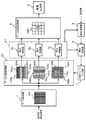
- FIG. 1 is a block diagram showing the configuration of a first embodiment of a two-dimensional radiation display apparatus according to the present invention.
- FIG. 1 is a block diagram showing a configuration of a first embodiment of a two-dimensional radiation display apparatus according to the present invention.
- a first embodiment of a two-dimensional radiation display apparatus according to the present invention will be described with reference to other drawings.
- the two-dimensional radiation display device includes a data acquisition unit 1, a data division processing unit 2, an integration processing unit 3, a data synthesis processing unit 4, and an image output unit 5.
- the integration processing unit 3 includes, for example, integration processing units 3a, 3b, and 3c for each region to be integrated.
- the two-dimensional radiation display apparatus of the first embodiment acquires the intensity distribution of radiation from a radiation detector (not shown).
- the radiation detector is, for example, a ⁇ -ray detector array including a plurality of ⁇ -ray detectors having pinholes or collimators.
- a gamma ray detector array having a pinhole is provided with, for example, an opening in the center of the shielding plate, and a plurality of gamma ray detectors are arranged so as to detect radiation incident from the opening of the shielding plate.
- the ⁇ -ray detector array having a collimator is provided with a plurality of hollow cylindrical collimators made of, for example, lead so as to correspond to the positions of the plurality of ⁇ -ray detectors.
- the two-dimensional radiation display device receives radiation detection signals from a plurality of arrayed radiation detectors and displays radiation distribution based on the radiation detection signals. Is output.
- each functional unit shown in FIG. 1 will be described.
- the data acquisition unit 1 acquires a radiation detection signal multiple times in a time series from a radiation detector (not shown) as described above. At this time, the data acquisition unit 1 also acquires position information as to which radiation detection signal is from which arrayed position in the radiation detector.
- the data acquisition unit 1 may be connected to the ⁇ -ray detector array by a signal line so that each ⁇ -ray detector can be identified from the ⁇ -ray detector array, for example. Radiation intensity data including position information may be received from the array.
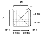
- the data acquisition unit 1 converts the acquired radiation detection signal (radiation intensity signal) into two-dimensional radiation data 101 in a two-dimensional array format of I (row) ⁇ J (column).
- I and J are integers, and are hereinafter expressed as resolution ⁇ I (row) ⁇ J (column) ⁇ .
- the two-dimensional radiation data 101 has radiation intensity data in a two-dimensional array format with a resolution ⁇ 16 (rows) ⁇ 16 (columns) ⁇ .
- FIG. 2 shows an example of the arrangement of the two-dimensional radiation data 101.
- the data acquisition unit 1 converts the radiation detection signal (or radiation intensity data, etc.) acquired from the radiation detector into two-dimensional radiation in a two-dimensional array format of I (row) ⁇ J (column) as shown in FIG. 2, for example. Convert to data 101.
- the data acquisition unit 1 associates the array of ⁇ -ray detector arrays with the resolution ⁇ I (row) ⁇ J (column) ⁇ of the two-dimensional radiation data 101. Note that such two-dimensional radiation data 101 includes detection position information and radiation intensity information, and therefore can be handled as three-dimensional.
- FIG. 2 shows an example of the upper and lower regions, the left region, and the right region with reference to the array arrangement direction in the ⁇ -ray detector array. Furthermore, an example of the diagonal direction is also shown.
- the upper area is from the first line to the I / 2 line (when I / 2 is an integer) from the first line of the two-dimensional array
- the lower area is the (I / 2 + 1) line to the I line.
- the inner region not shown is, for example, the range from the I / 4th row to the 3I / 4th row (in the case of an integer) from the J / 4th column to the 3J / 4th column (in the case of an integer) of the two-dimensional array.
- the outer region is a region other than the inner region.
- the data division processing unit 2 divides the two-dimensional radiation data 101 into a plurality of regions for each section capable of recognizing the direction in order to be able to recognize the radiation detection direction.
- the data division processing unit 2 divides the two-dimensional radiation data 101 into, for example, the upper and lower regions, the left and right regions, the inner (center) and the outer (other than the center) regions shown in FIG. Divided data 102a, 102b, and 102c having data are generated.
- the divided data 102a is data in which the two-dimensional radiation data 101 is divided into an upper region 102U and a lower region 102D obtained by dividing the data vertically.
- the divided data 102b is data obtained by dividing the two-dimensional radiation data 101 into left and right regions 102L and 102R of data obtained by dividing the two-dimensional radiation data 101 into left and right.
- the divided data 102c is data obtained by dividing the two-dimensional radiation data 101 into an inner region 102I and an outer region 102O that are divided into a central inner side and an outer side.
- the center is an area of the two-dimensional radiation data 101 corresponding to the center of the ⁇ -ray detector array.
- the dividing method of the two-dimensional radiation data 101 may be a dividing method other than the method shown in FIG.
- the two-dimensional radiation data 101 can be divided by diagonal lines, and the sections for specifying the directions can be made into four regions.
- the divided areas of the divided data 102a as described above correspond to the upper and lower areas on the display screen in the display device.
- the divided areas of the divided data 102b correspond to the left and right areas on the display screen, and the divided areas of the divided data 102c correspond to the center and areas other than the center on the display screen.
- the integration processing unit 3 performs integration processing on the two-dimensional radiation data 101 acquired multiple times in time series for each section into which the two-dimensional radiation data 101 is divided. That is, the integration processing unit 3a integrates the divided data 102a divided into the upper region 102U and the lower region 102D. Similarly, the integration processing unit 3b integrates the divided data 102b divided into the right region 102R and the left region 102L, and the integration processing unit 3c performs the divided data divided into the inner region 102I and the outer region 102O. 102c is integrated.
- the integration value is generated for each of the divided data 102a, 102b, and 102c by the integration processing unit 3 (3a, 3b, and 3c).
- the data synthesis processing unit 4 further divides and synthesizes the two-dimensional radiation data 101 integrated by the integration processing units 3a, 3b, and 3c. That is, the data composition processing unit 4 generates recombined two-dimensional data 104S.
- FIG. 3 shows an example of the recombination processing by the data composition processing unit 4.
- the data composition processing unit 4 converts each of the upper region 102U and the lower region 102D, the right region 102R and the left region 102L, the inner region 102I, and the outer region 102O into an integral value for each region. Based on the ratio, weighting (synthesizing) is performed as recombined two-dimensional data 104S.
- FIG. 3 shows the following weighting sections (1) to (8) and sections for specifying the direction (upper region 102U, lower region 102D, left region 102L, right region 102R, inner region 102I and outer region The correspondence relationship with the area 102O) is shown.
- the data composition processing unit 4 further generates the recombined two-dimensional data 104S by dividing the above-described direction specifying sections into sections (1) to (8) (8 divisions).
- the recombined two-dimensional data 104S is output from the data composition processing unit 4 to the image output unit 5.
- the image output unit 5 displays the radiation distribution of the re-synthesized two-dimensional data 104S on the display screen according to the integration results for each of the sections (1) to (8) by displaying grayscales such as color gradation and grayscale. To do. At that time, the image output unit 5 may display the visible image and the radiation distribution so as to overlap each other.
- the image output unit 5 uses, for example, a radiation image as described above in the visible image based on a viewing angle of a camera or the like that captures a visible image, and a viewing angle determined by a pin pole and a detector effective area for detecting radiation. Superimpose distribution images.
- the two-dimensional radiation display apparatus of this embodiment can display the radiation distribution image which shows the direction where the radiation is detected on the visible image and image
- FIG. 4 shows an example of the two-dimensional radiation display processing flow of the first embodiment.
- the two-dimensional radiation display processing flow of FIG. 4 will be described below with reference to FIGS.
- the data acquisition unit 1 acquires data from a radiation detector (not shown) a plurality of times after a time interval such as two-dimensional radiation data 101a,.
- the integration processing unit 3 integrates the two-dimensional radiation data 101a,..., 101n according to the division section of the data division processing unit 2.
- the integration processing unit 3a integrates the radiation intensity data in the respective ranges of the upper region 102U and the lower region 102D for the two-dimensional radiation data 101a,..., 101n, and as shown in FIG.
- An integral value 103a is obtained.
- the data synthesis processing unit 4 receives the integration values 103a, 103b, and 103c from the integration processing units 3a, 3b, and 3c, as shown in FIG. 4, the above-described division (1) to division (8) are weighted ( The recombined two-dimensional data 104S is generated by dividing the radiation intensity.
- the intensity distribution of the division ⁇ (1), (2), (3), (4), (5), (6), (7), (8) ⁇ ⁇ 0.224, 0 0.096, 0.144, 0.336, 0.056, 0.024, 0.036, 0.084 ⁇ .
- the image output unit 5 When the image output unit 5 receives the recombined two-dimensional data 104S from the data composition processing unit 4, the image output unit 5 outputs an image display output 105S on the display screen.
- the integrated values for each of the sections (1) to (8) described above are indicated by dot display / slanted line display so that the difference in intensity distribution for each section can be identified. Yes.
- the display is performed so that a difference in relative intensity can be recognized by using a display method (predetermined display format) such as grayscale display or color gradation display depending on the radiation intensity.
- this ⁇ -ray detector array requires counting of 100 data (counts) capable of recognizing the direction of radiation, and the counting time is set to 100 seconds. For example, when one detector in the ⁇ -ray detector array is considered, it takes a counting time of 100 seconds to count 100 ⁇ -rays.
- the resolution is better as I or J is larger.
- I or J the resolution is better as I or J is larger.
- the radiation is counted and integrated for each region of the segment specifying the direction such as the upper side and the lower side, the left side and the right side, the center side, and the outside.
- the two-dimensional radiation display apparatus of the first embodiment for example, two-dimensional radiation distribution data based on the areas of the sections that specify directions such as the upper side and the lower side, the left side and the right side, the center side, and the outside. Therefore, the detection direction of the radiation can be accurately grasped in a short time, and the contaminated part can be recognized in a short time.
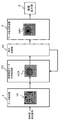
- FIG. 5 is a block diagram showing the configuration of the second embodiment of the two-dimensional radiation display apparatus according to the present invention.
- the second embodiment will be described with reference to FIG.
- the same reference numerals are given to the same functional units as those in the configuration of the first embodiment in FIG. 1.
- an integration determination unit 6, a determination feedback unit 7, and a setting switching unit 8 are further provided.
- I have. 1 are a data acquisition unit 1, a data division processing unit 21, an integration processing unit 31, a data synthesis processing unit 4, and an image output unit 5.
- the integration determination unit 6 receives each integration result (integration value) from the integration processing unit 3a, the integration processing unit 3b, and the integration processing unit 3c.
- the integral determination unit 6 determines whether or not the integral value of each region of the divided data 102a, 102b, and 102c is “sufficiently accurate” or “statistically significant”.
- the integral determination unit 6 notifies the determination feedback unit 7 of such an integral determination result.
- the determination feedback unit 7 receives the integration determination result from the integration determination unit 6, if it is determined that the integration value of each region is “sufficiently accurate” or “statistically significant”, An instruction is given to the data division processing unit 21 to increase the number of divisions for the area. On the other hand, if it is not determined that the integral value of the region is “sufficiently accurate” or “statistically significant”, the determination feedback unit 7 issues an instruction to maintain the number of divisions.
- the data division processing unit 21 determines whether or not to change the number of divisions of the two-dimensional radiation data 101 based on this instruction.
- the divided data 102a, 102b, and 102c in the data division processing unit 21 shown in FIG. 5 are in the divided state shown in FIG.
- the data division processing unit 21 receives an instruction from the determination feedback unit 7 to further subdivide the upper region of the divided data 102a into two regions based on the integral determination result, The first upper region 102Ua and the second upper region 102Ub are divided.
- the data division processing unit 21 receives an instruction from the determination feedback unit 7 to increase the number of divisions in the lower area of the divided data 102a, for example, the lower area is changed to the first lower area.
- the area 102Da is divided into a second lower area 102Db.
- the data division processing unit 21 receives an instruction from the determination feedback unit 7 to increase the number of divisions in the left area of the divided data 102b, for example, the left area is set as the first left area 102La. Dividing into the second left region 102Lb.
- the data division processing unit 21 receives an instruction from the determination feedback unit 7 to increase the number of divisions of the right area of the divided data 102b, for example, the right area is changed to the first right area 102Ra and the second right area 102Ra.
- the right area 102Rb is divided.
- the data division processing unit 21 divides, for example, one inner area of the divided data 102c into a first inner area 102Ia and a second inner area 102Ib.
- the outer region 102Oa is not divided in this example, but may be further divided and divided. Further, in the above example, the case where the division is determined for each region has been described. However, when it is determined that the number of divisions is increased for any one region, all the regions may be subdivided and divided. .
- the integration processing unit 31 similarly obtains integrated values in the subdivided areas of the divided data 102a, 102b, and 102c.
- the data synthesis processing unit 4 synthesizes the integration values for each section that specify the directions integrated by the integration processing units 3a, 3b, and 3c. Thereby, the data composition processing unit 4 generates recombined two-dimensional data 104T.
- FIG. 6 shows an example of the recombination processing by the data composition processing unit 4.
- the example shown in FIG. 6 is an example in which the 8 divisions shown in FIG. 3 are subdivided into 20 divisions.
- the recombined two-dimensional data 104T includes, for example, first and second upper regions 102Ua and Ub, first and second lower regions 102Da and Db, and first and second left regions 102La.
- Lb, the integrated values in each of the first and second right regions 102Ra and Rb, and the outer region 102Oa are weighted and synthesized by the data synthesis processing unit 4.
- FIG. 6 shows the following weighting (distribution) classifications (1) to (20) (when divided into 20) obtained from the above-mentioned area classifications.
- two-dimensional radiation data 101A as shown in FIG.
- the two-dimensional radiation data 101A and the like are integrated by the data division processing unit 21 and the integration processing unit 31, and the recombination two-dimensional data 104T shown in FIG.
- the image output unit 5 displays the recombined two-dimensional data 104T shown in FIG. 8 on the display screen like the image display output 105T shown in FIG. 8 according to the integration results for each of the sections (1) to (20).
- a two-dimensional radiation distribution is displayed by color gradation display or color shading display.
- the setting switching unit 8 sets or switches a determination criterion for determining the integration determination result of the integration determination unit 6, and sends the set value to the integration determination unit 6.
- the set value is an integral value as described later.
- the integration determination unit 6 determines whether the integration value S of each section is 10,000 or more. To do. Similarly, when the integral determination unit 6 determines that the accuracy at 1 ⁇ is 10% from the integral value of each section, for example, it is determined that the integral value S of each section is 100 or more. Although 10,000 and 100 of these integral values S are determination values depending on the accuracy, an arbitrary determination value can be set by the setting switching unit 8 as a setting value. Note that ⁇ is a standard deviation.
- the two-dimensional radiation data 101 is two-dimensional distribution data of radiation intensity (count value per unit time), but also includes a radiation count value due to scattering from structures around the radiation detector.
- the original distribution information is lost in the count value due to scattering. That is, each element (i, j) of the two-dimensional radiation data 101 generated by the data acquisition unit 1 is a scatter in which intensity distribution data and distribution information are lost with respect to a count value acquired from, for example, a ⁇ -ray radiation detector array. Data and are included.
- i is an integer of 1 to I
- j is an integer of 1 to J.
- Scattering data can be reduced by structures and shielding around the radiation detector, but not zero. Although the ratio cannot be zero, the ratio due to scattering in the integral value S can be obtained by designing the structure around the radiation detector, the shielding, or experiment. Let ⁇ be the ratio of scattering in the integrated value S. Although ⁇ may have a different value for each element (i, j), the maximum value among them may be used.
- (1 ⁇ ) ⁇ S is an integral value having direction information
- ⁇ ⁇ S is an integral value due to scattering
- the integral value having direction information has a variation of ⁇ ⁇ ((1- ⁇ ) S)
- the integral value due to scattering has a variation of ⁇ ⁇ ( ⁇ S).
- the integral value S at this time is regarded as “statistically significant” as a first determination value.
- Integral determination unit 6 determines “statistically significant” when, for example, integral value S obtained by integration processing unit 31 satisfies any one of (Expression 1) to (Expression 3).
- the integral determination unit 6, the determination feedback unit 7, and the setting switching unit 8 described above it is possible to automatically switch so as to further subdivide the category for specifying the direction. This switching is performed when the integral value of each section is “sufficiently accurate” or “statistically significant”. For example, even if it is divided into 8 divisions at the initial stage of radiation detection, it can be divided into detailed divisions such as the number of divisions exceeding that,. it can.
- a process for determining that the integral determination unit 6 is “sufficiently accurate” or “statistically significant” is provided with a manual setting means (not shown) so that the operator of the two-dimensional radiation display apparatus The subdivision may be manually set for the data division processing unit 21.
- the direction in which the radiation is detected can be recognized in a short time by using a small number of areas of top, bottom, left, and right and the center. can do. Further, by integrating for each section, detection sensitivity can be improved, and statistical variation can be suppressed in a short time. That is, it becomes possible to recognize the contaminated portion in a short time.
- the display can be switched to a further subdivided display with the upper, lower, left, and center sections as the radiation detection time elapses. It can be displayed higher.
- the subdivision can be performed up to the resolution of the two-dimensional radiation data 101.
- FIG. 9 is a block diagram showing the configuration of the third embodiment of the two-dimensional radiation display apparatus according to the present invention.
- the third embodiment will be described with reference to FIG.
- the same reference numerals are given to the same functional units as those in the configuration of the first embodiment in FIG. 1.
- the configuration shown in FIG. 9 is a configuration in which the data division processing unit 2 shown in the configuration of FIG. 1 is replaced with a region determination data division processing unit 22, and similarly, the integration processing unit 3 is replaced with an integration processing unit 32.
- the region determination data division processing unit 22 uses the integration result around the maximum value of the two-dimensional radiation data 101 acquired by the data acquisition unit 1, and the integration value is “sufficiently accurate” or “statistically A region satisfying “significant” and other regions are determined and divided according to the determination result.
- the integration processing unit 32 integrates the divided data 102X for each area divided by the area determination data division processing unit 22.
- the integration processing unit 32 sends the integration result for each divided region to the data synthesis processing unit 4 and also to the region determination data division processing unit 22.
- the region determination data division processing unit 22 determines that “there is sufficient accuracy” or “statistics”.
- the original judgment value that is “significantly significant” multiplied by a value of 1 or more is used as a new judgment value, and the area to be further divided is subdivided.
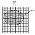
- FIG. 10 and 11 show an example of segmentation of the area to be divided by the area determination data division processing unit 22.
- FIG. 10 shows an example in which the integral determination value for dividing the region in the divided data 102X is set to 100.
- the area determination data division processing unit 22 first converts the divided data 102X into the first divided area 102Ic (broken line portion) and other areas, that is, the integral value is “sufficient.
- a region satisfying the determination value 100 of “accurate” or “statistically significant” and other regions are determined and divided.
- the shape of the area can be further subdivided and divided. For example, it is possible to narrow down and specify the range of the contaminated portion due to the radioactive substance.
- the direction can be specified with an arbitrary shape. Further, as the radiation detection time elapses, for example, the direction of a contaminated part due to a radioactive substance can be subdivided and specified.
- FIG. 12 is a block diagram showing the configuration of the fourth embodiment of the two-dimensional radiation display apparatus according to the present invention. Specifically, FIG. 12 is a block diagram of the configuration of a radiation monitor camera using the two-dimensional radiation display apparatus.
- the configuration of the two-dimensional radiation display device 52 shown in FIG. 12 is, for example, any one of the two-dimensional radiation display devices of the first to third embodiments described above. Here, a detailed description of the function of the two-dimensional radiation display device 52 is omitted.
- the radiation monitor camera 50 includes a ⁇ -ray detector array 51, a two-dimensional radiation display device 52, a visible camera device 53, a monitor adjustment unit 54, and a monitor 55.
- the ⁇ -ray detector array 51 is a ⁇ -ray detector array having a collimator, for example.
- the two-dimensional radiation display device 52 displays the two-dimensional radiation display by using, for example, an integrated circuit of the functions of the two-dimensional radiation display devices of the first to third embodiments described above or a computer including a CPU, a memory, a ROM, and the like. A program incorporating a processing function is incorporated.
- the visible camera device 53 is capable of photographing an object within the viewing angle of the camera, for example, with a CCD or the like, and outputs the visible image to the monitor adjustment unit 54 with a predetermined signal output.
- the monitor adjustment unit 54 superimposes the two-dimensional radiation image generated by the two-dimensional radiation display device 52 on the visible image captured by the visible camera device 53. For this purpose, the monitor adjustment unit 54 adjusts the display image to be synthesized based on the viewing angle of the visible camera device 53 and the viewing angle of the ⁇ -ray detector array 51. The monitor adjustment unit 54 adjusts the density or color gradation of the two-dimensional radiation image of the two-dimensional radiation display device 52.
- the monitor 55 has a display screen and outputs the synthesized display image to the display screen.
- the gamma ray detector was shown as an example as a radiation detector, and it is not intending limiting the range of invention. .
- the features of the embodiments may be combined.
- these embodiments can be implemented in various other forms, and various omissions, replacements, and changes can be made without departing from the scope of the invention.
- These embodiments and modifications thereof are included in the invention described in the claims and equivalents thereof as well as included in the scope and gist of the invention.
- SYMBOLS 1 Data acquisition part, 2, 21 ... Data division
Landscapes
- Physics & Mathematics (AREA)
- General Physics & Mathematics (AREA)
- High Energy & Nuclear Physics (AREA)
- Life Sciences & Earth Sciences (AREA)
- Spectroscopy & Molecular Physics (AREA)
- Molecular Biology (AREA)
- Health & Medical Sciences (AREA)
- Engineering & Computer Science (AREA)
- Theoretical Computer Science (AREA)
- General Life Sciences & Earth Sciences (AREA)
- Geophysics (AREA)
- Measurement Of Radiation (AREA)
- Environmental & Geological Engineering (AREA)
- Geology (AREA)
- Nuclear Medicine (AREA)
Abstract
2次元放射線表示装置は、複数の放射線検出器から複数回検出された2次元放射線データ(101)を取得するデータ取得部(1)と、2次元放射線データ(101)を方向を特定する区分ごとのデータ領域に分割するデータ分割処理部(2)と、複数回検出された2次元放射線データ(101)について方向を特定する区分ごとに積分する積分処理部(3)と、積分された方向を特定する区分ごとの積分値を放射線分布を示す2次元データに合成するデータ合成処理部(4)と、放射線分布を示す2次元データを所定の表示形式に従った表示データとして出力する画像出力部(5)とを備えている。
Description
本発明の実施形態は、2次元放射線表示装置および2次元放射線表示方法に関する。
2次元放射線表示装置は、放射線源の方向を2次元の配置で、強さを色や輝度で画面に表示する装置である。CCD(Charge Coupled Device)イメージセンサ等により撮影した可視画像に放射線源の方向を重ね合わせて表示することにより、直感的に放射線源の方向と強さを認識することができる。
2次元の放射線強度分布データを得るために用いられる手法として、放射線検出器を2次元のアレイ状に並べて個々の放射線検出器の出力(パルス計数値、電流値、電圧値など)を2次元配列に並べたもの、放射線の入射により発光するシンチレータをCCDカメラ等で撮影したものなどが知られている。
なお、γ線検出器アレイをγ線の入射方向を回転軸として回転させて複数回γ線の強度を検出して放射能分布を撮影するγ線放射能分布撮影方法であって、最小二乗法によるフィッティング計算により所定の式が最小となる放射能強度及びγ線検出器の感度の相対値を求め、所定の式のフィッティング計算を繰り返し行い、放射性物質の放射能分布を求めること等が開示されている。
また、原子力施設の工事等で現場に帯行・設置し、放射線作業環境を把握できる、高感度化・小型化を目的とした、阻止能の高いCdTe半導体センサアレイと大口径シングルホールコリメータを組み合わせたγ線イメージング装置等が開示されている。
日本原子力学会 2002年秋の大会 D38 「CdTeアレイを用いた小型高感度γ線イメージング装置の開発」
原子力発電所等における事故により汚染された地域においては速やかな放射性物質の除染が求められている。しかし、従来の線量計では放射性物質による汚染箇所を把握するのに時間がかかり、効率的に除染作業を進めることが難しい。
汚染箇所を認識することが容易な2次元放射線表示装置は、除染作業の効率向上を実現するツールとして有効である。しかし、低空間線量環境において、汚染箇所を認識するまでには時間がかかる問題がある。
除染作業を開始する前に汚染箇所を認識することができれば、放射性物質による汚染箇所のみを除染することで、除染作業を効率的に実施することができる。さらに、除染後の汚染箇所の除染確認作業も同様である。
本発明の実施形態が解決しようとする課題は、短時間で放射性物質による汚染箇所を認識することができる2次元放射線表示装置および2次元放射線表示方法を提供することである。
上記課題を解決するために、一つの実施形態の2次元放射線表示装置は、2次元的に配列されたアレイ状の複数の放射線検出器から放射線検出信号を受けて、当該放射線検出信号に基づいて放射線分布を表示するための表示データを出力可能な2次元放射線表示装置である。当該2次元放射線表示装置は、前記複数の放射線検出器から複数回検出された前記放射線検出信号から前記アレイ状の位置に対応する2次元放射線データに変換するデータ取得部と、前記データ取得部により変換された前記2次元放射線データを、方向を特定する区分の領域ごとに分割するデータ分割処理部と、前記データ分割処理部により分割された前記方向を特定する区分の領域ごとに、前記2次元放射線データを積分する積分処理部と、前記積分処理部により積分された前記方向を特定する区分の領域ごとの積分値に基づいて、放射線分布を示す2次元データを合成するデータ合成処理部と、前記データ合成処理部により合成された前記2次元データを所定の表示形式に従った表示データとして出力する画像出力部とを備えることを特徴とする。
また、他の実施形態の2次元放射線表示装置は、2次元的に配列されたアレイ状の複数の放射線検出器から放射線検出信号を受けて、当該放射線検出信号に基づいて放射線分布を表示するための表示データを出力可能な2次元放射線表示装置である。当該2次元放射線表示装置は、前記複数の放射線検出器から複数回検出された前記放射線検出信号から前記アレイ状の位置に対応する2次元放射線データに変換するデータ取得部と、前記データ取得部により変換された前記2次元放射線データを、領域を分割するための基準となる判定値に従って、当該判定値以上の分割する領域判定データ分割処理部と、前記領域判定データ分割処理部により分割された前記領域ごとに、前記2次元放射線データを積分する積分処理部と、前記積分処理部により積分された前記方向を特定する区分の領域ごとの積分値に基づいて、放射線分布を示す2次元データを合成するデータ合成処理部と、前記データ合成処理部により合成された前記2次元データを所定の表示形式に従った表示データとして出力する画像出力部とを備え、前記領域判定データ分割処理部は、前記判定値を前記積分値の精度または統計的に有意な値に基づいて決定し、当該決定した判定値を基準として前記2次元放射線データを分割することを特徴とする。
上記課題を解決するために、一つの実施形態の2次元放射線表示方法は、2次元的に配列されたアレイ状の複数の放射線検出器から放射線検出信号を受けて、当該放射線検出信号に基づいて放射線分布を表示するための表示データを出力可能な2次元放射線表示装置の2次元放射線表示方法である。当該2次元放射線表示方法は、前記2次元放射線表示装置のデータ取得手段が、前記複数の放射線検出器から複数回検出された前記放射線検出信号から前記アレイ状の位置に対応する2次元放射線データに変換するデータ取得ステップと、前記2次元放射線表示装置のデータ分割処理手段が、前記データ取得ステップにおいて変換された前記2次元放射線データを、方向を特定する区分の領域ごとに分割するデータ分割処理ステップと、前記2次元放射線表示装置の積分処理手段が、前記データ分割処理ステップにおいて分割された前記方向を特定する区分の領域ごとに、前記2次元放射線データを積分する積分処理ステップと、前記2次元放射線表示装置のデータ合成処理手段が、前記積分処理ステップにおいて積分された前記方向を特定する区分の領域ごとの積分値に基づいて、放射線分布を示す2次元データを合成するデータ合成処理ステップと、前記2次元放射線表示装置の画像出力手段が、前記データ合成処理ステップにおいて合成された前記2次元データを所定の表示形式に従った表示データとして出力する画像出力ステップとを有することを特徴とする。
また、他の実施形態の2次元放射線表示方法は、2次元的に配列されたアレイ状の複数の放射線検出器から放射線検出信号を受けて、当該放射線検出信号に基づいて放射線分布を表示するための表示データを出力可能な2次元放射線表示装置の2次元放射線表示方法である。当該2次元放射線表示方法は、前記2次元放射線表示装置のデータ取得手段が、前記複数の放射線検出器から複数回検出された前記放射線検出信号から前記アレイ状の位置に対応する2次元放射線データに変換するデータ取得ステップと、前記2次元放射線表示装置の領域判定データ分割処理部手段が、前記データ取得ステップにおいて変換された前記2次元放射線データを、領域を分割するための基準となる判定値に従って、分割する領域判定データ分割処理ステップと、前記2次元放射線表示装置の積分処理手段が、前記領域判定データ分割処理ステップにおいて分割された前記領域ごとに、前記2次元放射線データを積分する積分処理ステップと、前記2次元放射線表示装置のデータ合成処理手段が、前記積分処理ステップにおいて積分された前記分割された領域ごとの積分値に基づいて、放射線分布を示す2次元データを合成するデータ合成処理ステップと、前記2次元放射線表示装置の画像出力手段が、前記データ合成処理ステップにおいて合成された前記2次元データを所定の表示形式に従った表示データとして出力する画像出力ステップとを有し、前記領域判定データ分割処理ステップでは、前記領域を分割するための基準となる判定値を前記積分値の精度または統計的に有意な値に基づいて決定し、当該決定した判定値を基準として前記2次元放射線データを分割することを特徴とする。
本発明に係る2次元放射線表示装置および2次元放射線表示方法の実施形態によれば、短時間で放射性物質による汚染箇所を認識することができる。
以下、本発明に係る実施形態の2次元放射線表示装置について、図面を参照して具体的に説明する。ここで、互いに同一または類似の部分には共通の符号を付して、重複説明は省略する。ここで説明する下記の実施形態はいずれも、放射線検出器としてγ線検出器に用いる2次元放射線表示装置の一例をとりあげて説明する。
[第1の実施形態]
図1は、本発明に係る2次元放射線表示装置の第1の実施形態の構成を示すブロック図である。以下、本発明に係る2次元放射線表示装置の第1の実施形態について、その他の図面も参照しながら説明する。
図1は、本発明に係る2次元放射線表示装置の第1の実施形態の構成を示すブロック図である。以下、本発明に係る2次元放射線表示装置の第1の実施形態について、その他の図面も参照しながら説明する。
2次元放射線表示装置は、図1に示すように、データ取得部1、データ分割処理部2、積分処理部3、データ合成処理部4、画像出力部5を備えている。積分処理部3は、積分する領域毎に、例えば積分処理部3a、3bおよび3cを備えている。
第1の実施形態の2次元放射線表示装置は、図示しない放射線検出器から放射線の強度分布を取得する。放射線検出器は、例えばピンホールまたはコリメータを有する複数のγ線検出器からなるγ線検出器アレイなどである。
具体的には、ピンホールを有するγ線検出器アレイは、例えば遮へい板の中央に開孔が設けられ、その遮へい板の開孔から入射する放射線を検出するように複数のγ線検出器が設けられている。また、コリメータを有するγ線検出器アレイは、例えば鉛で形成された中空筒状のコリメータが複数のγ線検出器の位置に対応するように複数設けられている。これによって、放射性物質から放出されるγ線がコリメータを通過し、このコリメータを通過したγ線が複数のγ線検出器で検出される。
第1の実施形態の2次元放射線表示装置は、詳しくは後述するように、アレイ状の複数の放射線検出器から放射線検出信号を受けて、当該放射線検出信号に基づいて放射線分布を表示する表示データを出力する。以下、図1に示す各機能部について説明する。
データ取得部1は、上述したような図示しない放射線検出器から放射線検出信号を時系列的に複数回取得する。この際に、データ取得部1は、放射線検出器におけるどのアレイ状の位置からの放射線検出信号であるかの位置情報も取得する。このために、データ取得部1は、例えばγ線検出器アレイから各々のγ線検出器を識別可能なように信号線でγ線検出器アレイに接続されてもよく、また、γ線検出器アレイから位置情報を含む放射線強度データを受信してもよい。
データ取得部1は、この取得した放射線検出信号(放射線の強度信号)を、I(行)×J(列)の2次元配列形式の2次元放射線データ101に変換する。ここで、I、Jは整数であり、以降では分解能{I(行)×J(列)}のように表すものとする。例えば、2次元放射線データ101は、分解能{16(行)×16(列)}の2次元配列形式で放射線強度データを有する。
図2に、2次元放射線データ101の配列の一例を示す。
データ取得部1は、放射線検出器から取得した放射線検出信号(または放射線強度データなど)を、例えば図2に示すように、I(行)×J(列)の2次元配列形式の2次元放射線データ101に変換する。データ取得部1は、γ線検出器アレイの配列を2次元放射線データ101の分解能{I(行)×J(列)}に対応させる。なお、このような2次元放射線データ101は、検出の位置情報および放射線の強度情報を有することから、3次元としても扱うことができる。
また、図2に、γ線検出器アレイにおけるアレイ状配置方向を基準とした上側および下側、左側および右側の領域の例を示す。さらに、対角線方向の例も示す。例えば、上側の領域は2次元配列の1行目から~I/2行目(I/2が整数の場合)であり、下側の領域は(I/2+1)行目~I行目である。なお、図示しない内側領域は、例えば2次元配列のI/4行目から~3I/4行目(整数の場合)、J/4列目から~3J/4列目(整数の場合)の範囲の領域であり、外側領域は内側領域以外である。
データ分割処理部2は、放射線の検出方向を認識可能とするために、その方向を認識可能な区分ごとに、2次元放射線データ101を複数の領域に分割する。データ分割処理部2は、2次元放射線データ101について、例えば前述した図2に示す上側および下側領域、左側および右側領域、内側(中央)および外側(中央以外)の領域の区分にそれぞれ分割したデータを有する分割データ102a、102b、102cを生成する。
図1に示すように、分割データ102aは、2次元放射線データ101が上下に分割された上側領域102Uおよび下側領域102Dに区分されたデータである。また、分割データ102bは、2次元放射線データ101が左右に分割されたデータの左側領域102Lおよび右側領域102Rに区分されたデータである。また、分割データ102cは、2次元放射線データ101が中央の内側と外側とに分割された内側領域102Iおよび外側領域102Oとに区分されたデータである。なお、例えば、中央はγ線検出器アレイの中央に対応する2次元放射線データ101の領域である。
ここで、2次元放射線データ101の分割方法は、図1に示す方法以外の分割方法であってもよい。例えば、図2に示すように、2次元放射線データ101を対角線で区切り、方向を特定する区分を4つの領域とすることもできる。
上述したような分割データ102aの分割された領域は、表示装置における表示画面での上下の領域に対応する。また、分割データ102bの分割された領域は表示画面での左右の領域に対応し、また、分割データ102cの分割された領域は表示画面での中央と中央以外の領域に対応する。
積分処理部3は、2次元放射線データ101が分割された区分ごとに、時系列的に複数回取得された2次元放射線データ101について積分処理を行う。すなわち、積分処理部3aは、上側領域102Uと下側領域102Dとに区分された分割データ102aを積分する。同様に、積分処理部3bは、右側領域102Rと左側領域102Lとに区分された分割データ102bを積分し、また、積分処理部3cは、内側領域102Iと外側領域102Oとに区分された分割データ102cを積分する。
以上説明した通り、積分処理部3(3a、3bおよび3c)により、これらの分割データ102a、102bおよび102cごとに、積分値が生成される。
データ合成処理部4は、積分処理部3a、3bおよび3cにより積分処理された2次元放射線データ101を、さらに区分して合成する。すなわち、データ合成処理部4は、再合成2次元データ104Sを生成する。
図3に、データ合成処理部4による再合成処理の一例を示す。
データ合成処理部4は、図3に示すように、例えば上側領域102Uおよび下側領域102D、右側領域102Rおよび左側領域102L、内側領域102Iおよび外側領域102Oの各々を、その領域ごとの積分値の比に基づいて、再合成2次元データ104Sとして重み付け(合成)する。
例えば、図3は、以下のような重み付けの区分(1)~(8)と、方向を特定する区分(上側領域102U、下側領域102D、左側領域102L、右側領域102R、内側領域102Iおよび外側領域102O)との対応関係を示す。
上側領域102U{区分(1)~(4)の範囲}
下側領域102D{区分(5)~(8)の範囲}
左側領域102L{区分(1)、(2)、(5)、(6)の範囲}
右側領域102R{区分(3)、(4)、(7)、(8)の範囲}
内側領域102I{区分(2)、(3)、(6)、(7)の範囲}
外側領域102O{区分(1)、(4)、(5)、(8)の範囲}
以上のように、データ合成処理部4は、上記の方向を特定する区分を、さらに、区分(1)~(8)(8分割)のようにして、再合成2次元データ104Sを生成する。この再合成2次元データ104Sは、データ合成処理部4から画像出力部5に出力される。
下側領域102D{区分(5)~(8)の範囲}
左側領域102L{区分(1)、(2)、(5)、(6)の範囲}
右側領域102R{区分(3)、(4)、(7)、(8)の範囲}
内側領域102I{区分(2)、(3)、(6)、(7)の範囲}
外側領域102O{区分(1)、(4)、(5)、(8)の範囲}
以上のように、データ合成処理部4は、上記の方向を特定する区分を、さらに、区分(1)~(8)(8分割)のようにして、再合成2次元データ104Sを生成する。この再合成2次元データ104Sは、データ合成処理部4から画像出力部5に出力される。
画像出力部5は、再合成2次元データ104Sをその区分(1)~(8)ごとの積分結果に応じて、表示画面上に色階調表示やグレースケールなどの濃淡表示によって放射線分布を表示する。その際に、画像出力部5が、可視画像と放射線分布とを重ね合わせて表示させてもよい。
この場合に、画像出力部5は、例えば可視画像を捉えるカメラなどの視野角と、放射線を検出するピンポールおよび検出器有効面積とにより定まる視野角とに基づいて、可視画像に上述したような放射線分布画像を重ね合わせる。これにより、本実施形態の2次元放射線表示装置は、撮影している可視画像や映像上に、放射線が検出されている方向を示す放射線分布画像を表示させることができる。
図4に、第1の実施形態の2次元放射線表示処理フローの一例を示す。以下、図1~図3を参照しながら、図4の2次元放射線表示処理フローについて説明する。
データ取得部1は、2次元放射線データ101a、・・・、101nのように時間間隔を経て、図示しない放射線検出器から複数回データを取得する。積分処理部3は、データ分割処理部2の分割区分に従って、2次元放射線データ101a、・・・、101nを積分する。
すなわち、積分処理部3aは、2次元放射線データ101a、・・・、101nについて、上側領域102Uおよび下側領域102Dのそれぞれの範囲にある放射線強度データを積分して、図4に示すように、積分値103aを得る。例えば、図4の例では、全領域の放射線強度を1とした場合に、上側領域102Uの積分値:下側領域102Dの積分値=0.8:0.2であることを示す。これと同様に、積分値103bでは、左側領域102Lの積分値:右側領域102Rの積分値=0.4:0.6である。また、積分値103cでは、内側領域102Iの積分値:外側領域102Oの積分値=0.3:0.7であることを示す。
データ合成処理部4は、積分処理部3a、3bおよび3cから上記の積分値103a、103bおよび103cを受けると、図4に示すように、前述した区分(1)~区分(8)に重み付け(放射線強度の振り分け)して再合成2次元データ104Sを生成する。
図4の例では、区分{(1)、(2)、(3)、(4)、(5)、(6)、(7)、(8)}の強度分布={0.224、0.096、0.144、0.336、0.056、0.024、0.036、0.084}である。
画像出力部5は、この再合成2次元データ104Sをデータ合成処理部4から受けると、表示画面に画像表示出力105Sを出力する。例えば、図4に示す例では、前述した区分(1)~(8)ごとの積分値が、当該区分ごとの強度分布の相違が識別可能となるように、ドット表示・斜線表示等で示している。実際には、放射線強度によって、濃淡表示や色階調表示などの表示方法(所定の表示形式)を用いて、相対的な強度の相違が分かるように表示される。
次に、第1の実施形態における検出感度の向上について説明する。例えば、2次元放射線データ101の分解能がI(行)×J(列)の場合、積分処理部3aでは上側領域102UにあるI/2×J個のデータを積分する。よって、再合成2次元データ104Sは、2次元放射線データ101の各要素に対してI/2×J倍の感度を有することになり、計数値が向上する。例えば、I=J=16とした場合、I/2×J=128となり、128倍の感度で放射線分布を表示することができる。
具体例で説明すると、例えば放射線検出器にγ線検出器アレイを用いる場合、分解能256ピクセル{16(行)×16(列)}を有するとする。また、このγ線検出器アレイで、放射線の方向を認識できるデータ数100(カウント)の計数が必要とし、さらにこの計数時間を100秒とする。これは、例えばγ線検出器アレイ中の1個の検出器で考えた場合には、γ線を100カウント計数するのに100秒の計数時間を要する。
これを、図1に示す2次元放射線表示装置の場合で説明すると、データ分割処理部2が2次元放射線データ101を、分割データ102aについて上側領域102Uおよび下側領域102Dのそれぞれに対して、128(=256/2)ピクセル分のデータを割り当てる。
積分処理部3aは、この128ピクセル分のデータ割り当てに対して積分するため、1ピクセルでデータ数100(カウント)を計数する場合と比べて、128倍の感度を得ることができる。すなわち、放射線の方向として上下方向を特定するために必要な計数時間は、0.78秒(=100秒/128)で済む。左右方向等の他の方向の区分についても同様である。
以上説明したように、2次元放射線データ101の配列I(行)×J(列)において、分解能はIまたはJが大きいほどすぐれているが、すべての配列要素に放射線が検出されるためには、長い時間を要することになる。
一方、第1の実施形態の2次元放射線表示装置によれば、例えば上側および下側、左側および右側、中央側およびその外側などの方向を特定する区分の領域ごとに、放射線を計数して積分することで、検出感度を向上し、統計的なばらつきを短時間で抑制することができる。
また、第1の実施形態の2次元放射線表示装置によれば、例えば上側および下側、左側および右側、中央側およびその外側などの方向を特定する区分の領域に基づいて、2次元放射線分布データを再合成するため、短時間で放射線の検出方向を的確にとらえることができ、汚染箇所を短時間で認識することが可能となる。
したがって、低空間線量の環境においても、汚染箇所を短時間で認識することが可能となる。
[第2の実施形態]
図5は、本発明に係る2次元放射線表示装置の第2の実施形態の構成を示すブロック図である。図5を参照しながら、第2の実施形態について説明する。なお、図5では、図1の第1の実施形態の構成と同一の機能部については同一の符号を付す。
図5は、本発明に係る2次元放射線表示装置の第2の実施形態の構成を示すブロック図である。図5を参照しながら、第2の実施形態について説明する。なお、図5では、図1の第1の実施形態の構成と同一の機能部については同一の符号を付す。
第2の実施形態の図5に示す構成では、第1の実施形態の図1に示す構成に相当する機能部に加えて、さらに、積分判定部6、判定フィードバック部7および設定切替部8を備えている。なお、図1の構成に相当する機能部は、データ取得部1、データ分割処理部21、積分処理部31、データ合成処理部4および画像出力部5である。
積分判定部6は、積分処理部3a、積分処理部3bおよび積分処理部3cからそれぞれの積分結果(積分値)を受ける。積分判定部6は、分割データ102a、102bおよび102cの各領域の積分値について、「十分な精度がある」または「統計的に有意」であるか否かを判定する。積分判定部6は、このような積分判定結果を、判定フィードバック部7に通知する。
判定フィードバック部7は、積分判定部6からこの積分判定結果を受けると、各領域の積分値ごとに「十分な精度がある」または「統計的に有意」であると判定されている場合、当該領域について分割数を増加するようにデータ分割処理部21に指示を出す。一方、当該領域の積分値について「十分な精度がある」または「統計的に有意」であると判定されていない場合、判定フィードバック部7は分割数を維持するように指示を出す。
データ分割処理部21は、判定フィードバック部7からの指示を受けると、この指示に基づいて2次元放射線データ101の分割数を変更するか否か判断する。
図5に示すデータ分割処理部21における分割データ102a、102bおよび102cが、例えば放射線検出の初期時には、図1に示す分割状態(上下2区分、左右2区分、内外2区分)であったとする。放射線検出の時間経過と共に積分値が大きくなると、データ分割処理部21が、積分判定結果に基づいて分割データ102aの上側領域をさらに2領域に細分化すると判定フィードバック部7から指示を受けた場合、第1の上側領域102Ua、第2の上側領域102Ubに分割する。
また、同様に、データ分割処理部21が、判定フィードバック部7から分割データ102aの下側領域の分割数を増加するように指示を受けた場合、例えば下側の1領域を第1の下側領域102Daと第2の下側領域102Dbに分割する。
また、同様に、データ分割処理部21が、判定フィードバック部7から分割データ102bの左側領域の分割数を増加するように指示を受けた場合、例えば左側の1領域を第1の左側領域102Laと第2の左側領域102Lbに分割する。また、データ分割処理部21が、判定フィードバック部7から分割データ102bの右側領域の分割数を増加するように指示を受けた場合、例えば右側の1領域を第1の右側領域102Raと第2の右側領域102Rbに分割する。内側領域の分割についても、同様に、データ分割処理部21が、分割データ102cについて、例えば内側の1領域を第1の内側領域102Iaと第2の内側領域102Ibに分割する。
なお、外側領域102Oaについては、本例では分割しないが、さらに細分化して分割するようにしてもよい。また、上記例では、各々の領域ごとに分割を判定する場合を示したが、いずれかひとつの領域について分割数を増やすと判定した場合にすべての領域を細分化して分割するようにしてもよい。
これらの細分化された方向を特定する区分ごとに、積分処理部31は、同様に、分割データ102a、102bおよび102cの細分化された領域での積分値を求める。
データ合成処理部4は、積分処理部3a、3bおよび3cにより積分された方向を特定する区分ごとの積分値を合成する。これにより、データ合成処理部4は、再合成2次元データ104Tを生成する。
図6に、データ合成処理部4による再合成処理の一例を示す。なお、図6に示す例は、図3に示す8分割の区分を20分割に細分化した一例である。
図6に示すように、再合成2次元データ104Tは、例えば第1および第2の上側領域102UaおよびUb、第1および第2の下側領域102DaおよびDb、第1および第2の左側領域102LaおよびLb、第1および第2の右側領域102RaおよびRb、外側領域102Oaの各々での積分値がデータ合成処理部4により重み付けされて合成される。
例えば、図6は、上記の領域の区分から得られる、以下のような重み付け(振り分け)の区分(1)~(20)(20分割された場合)を示す。
第1の上側領域102Ua{区分(1)~(4)の範囲}
第2の上側領域102Ub{区分(5)~(10)の範囲}
第1の下側領域102Da{区分(11)~(16)の範囲}
第2の下側領域102Db{区分(17)~(20)の範囲}
第1の左側領域102La{区分(1)、(5)、(11)、(17)の範囲}
第2の左側領域102Lb{区分(2)、(6)、(7)、(12)、(13)、(18)の範囲}
第1の右側領域102Ra{区分(3)、(8)、(9)、(14)、(15)、(19)の範囲}
第2の右側領域102Rb{区分(4)、(10)、(16)、(20)の範囲}
第1の内側領域102Ia{区分(7)、(8)、(13)、(14)の範囲}
第2の内側領域102Ib{区分(6)、(9)、(12)、(15)の範囲}
外側領域102Oa{区分(1)~(4)、(5)、(10)、(11)、(16)、(17)~(20)の範囲}
以上のように、データ合成処理部4は、上記の方向を特定する区分を、さらに、例えば区分(1)~(20)のようにして、再合成2次元データ104Tを生成する。この再合成2次元データ104Tは、データ合成処理部4から画像出力部5に出力される。
例えば、データ取得部1に、図7に示すような2次元放射線データ101A等が複数回取得されたとする。これらの2次元放射線データ101A等が、データ分割処理部21および積分処理部31により積分処理され、データ合成処理部4により図8に示す再合成2次元データ104Tが生成される。
画像出力部5は、図8に示す再合成2次元データ104Tをその区分(1)~(20)ごとの積分結果に応じて、図8に示す画像表示出力105Tのように、表示画面上に色階調表示や色の濃淡表示などによって2次元放射線分布を表示する。
設定切替部8は、積分判定部6の積分判定結果を判定するための判定基準を設定または切り替え、積分判定部6に当該設定値を送る。例えば、設定値は後述するような積分値である。
以下に、積分判定部6の精度(「十分な精度がある」)の判定処理の一例について説明する。
積分判定部6が、各データ分割領域(区分)の積分値から1σにおける精度が1%であることを判定する場合には、例えば各区分の積分値Sが10,000以上であるかを判定する。また、積分判定部6が、同様に各区分の積分値から1σにおける精度が10%であることを判定する場合には、例えば各区分の積分値Sが100以上であることを判定する。これらの積分値Sの10,000や100は精度に依存した判定値であるが、設定切替部8により任意の判定値を設定値により設定可能とする。なお、σは標準偏差である。
次に、積分判定部6の「統計的に有意」の判定処理の一例について説明する。
一般的に、2次元放射線データ101は放射線の強度(単位時間あたりの計数値)の2次元分布データであるが、放射線検出器の周囲の構造物との散乱による放射線の計数値も含まれる。散乱による計数値は、本来の分布情報が失われている。すなわち、データ取得部1が生成する2次元放射線データ101の各要素(i,j)は、例えばγ線放射線検出器アレイから取得される計数値ついて、強度分布データと分布情報が失われた散乱データとが含まれている。これは、各区分の計数値を積分して得られる積分値Sについても同様である。なお、2次元放射線データ101の配列I(行)×J(列)において、iは1以上I以下の整数であり、jは1以上J以下の整数である。
散乱データは、放射線検出器の周囲の構造物や遮蔽により低減することができるがゼロにはできない。ゼロにはできないが、積分値Sにおける散乱による割合は、放射線検出器周辺の構造や遮蔽の設計、または実験により求めることができる。積分値Sにおける散乱による割合をαとする。αは正確には各要素(i,j)で異なる値の場合もあるが、この中の最大値を用いてもよい。
ここで、積分値Sにおいて、(1-α)×Sが方向情報を有する積分値であって、α×Sが散乱による積分値である。このとき、方向情報を有する積分値は±√((1-α)S)、散乱による積分値は±√(αS)のばらつきを有する。積分値Sが散乱による積分値に対して統計的に有意であるためには、
((1-α)S-√((1-α)S))>(αS+√(αS)) (式1)
を満足する積分値Sであり、このときの積分値Sを「統計的に有意」とみなして第1の判定値とする。なお、1σ程度では十分に有意なとは言えない場合は、3σ程度としてもよい。その場合、
((1-α)S-3√((1-α)S))>(αS+3√(αS)) (式2)
を満足する積分値Sを第2の判定値とする。
((1-α)S-√((1-α)S))>(αS+√(αS)) (式1)
を満足する積分値Sであり、このときの積分値Sを「統計的に有意」とみなして第1の判定値とする。なお、1σ程度では十分に有意なとは言えない場合は、3σ程度としてもよい。その場合、
((1-α)S-3√((1-α)S))>(αS+3√(αS)) (式2)
を満足する積分値Sを第2の判定値とする。
1σとするか3σとするかは任意であり、さらにXを任意の数として、Xσについて、
((1-α)S-X√((1-α)S))>(αS+X√(αS)) (式3)
を満たす積分値Sを第3の判定値としてもよい。
((1-α)S-X√((1-α)S))>(αS+X√(αS)) (式3)
を満たす積分値Sを第3の判定値としてもよい。
積分判定部6は、例えば積分処理部31によって求められた積分値Sが(式1)ないし(式3)のいずれかを満たすときに、「統計的に有意」と判定する。
以上説明した積分判定部6、判定フィードバック部7および設定切替部8を設けることにより、方向を特定する区分をさらに細分化するように自動的に切り替えることができる。この切り替えは、各区分の積分値が、「十分な精度がある」場合、または、「統計的に有意」である場合に行なう。例えば、これにより、放射線の検出初期時には8分割で区分した場合でも、上記細分化するような切り替えにより、それを超える分割数、・・・、20分割数等に、詳細な区分にすることができる。
なお、積分判定部6が「十分な精度がある」または「統計的に有意」であることを判定している処理を、図示しない手動設定手段を設けて、2次元放射線表示装置の操作者がデータ分割処理部21に対して細分化を手動設定できるようにしてもよい。
2次元放射線データ101の配列I(行)×J(列)において、IまたはJが大きいほど分解能は高くなるが、すべての配列要素に放射線が検出されるためには、多くの時間を要する。
しかし、第2の実施形態の2次元放射線表示装置によれば、放射線の検出初期時には、上下、左右、中央の少ない区分の領域数にすることにより、放射線の検出される方向を短時間で認識することができる。またその区分ごとに積分することで検出感度を向上させ、統計的なばらつきを短時間で抑制することができる。すなわち、短時間で汚染箇所を認識することが可能となる。
さらに、第2の実施形態の2次元放射線表示装置によれば、放射線の検出時間の経過と共に、上下、左右、中央の区分の領域をさらに細分化した表示に切り替えることができるため、さらに分解能を高めて表示することができる。細分化は2次元放射線データ101の分解能まで行うことができる。
[第3の実施形態]
図9は、本発明に係る2次元放射線表示装置の第3の実施形態の構成を示すブロック図である。図9を参照しながら、第3の実施形態について説明する。なお、図9では、図1の第1の実施形態の構成と同一の機能部については同一の符号を付す。また、図9に示す構成は、図1の構成に示すデータ分割処理部2を領域判定データ分割処理部22に置き換え、同じく、積分処理部3を積分処理部32に置き換えた構成である。
図9は、本発明に係る2次元放射線表示装置の第3の実施形態の構成を示すブロック図である。図9を参照しながら、第3の実施形態について説明する。なお、図9では、図1の第1の実施形態の構成と同一の機能部については同一の符号を付す。また、図9に示す構成は、図1の構成に示すデータ分割処理部2を領域判定データ分割処理部22に置き換え、同じく、積分処理部3を積分処理部32に置き換えた構成である。
領域判定データ分割処理部22は、データ取得部1により取得された2次元放射線データ101の最大値の周囲での積分結果を用いて、積分値が「十分な精度がある」または「統計的に有意」を満足する領域とそれ以外の領域とを判定し、その判定結果に応じて分割する。
積分処理部32は、分割データ102Xを、領域判定データ分割処理部22により分割された領域ごとに、積分処理する。積分処理部32は、この分割された領域ごとの積分結果をデータ合成処理部4に送ると共に、領域判定データ分割処理部22にも送る。
積分処理部32による積分値がそれまでの判定値(元の判定値)よりもさらに大きな値になった場合には、領域判定データ分割処理部22は、「十分な精度がある」または「統計的に有意」とした元の判定値に1以上の値を乗じたものを新たな判定値として用い、さらに分割する領域を細分化する。
図10および図11に、領域判定データ分割処理部22による分割する領域の細分化の例を示す。図10は、分割データ102Xにおける領域を区分するための積分の判定値=100とした場合の例である。また、図11は、分割データ102Yにおける領域を区分するため、はじめに積分の判定値=100として、その次に積分の判定値=400とした場合の例である。
具体的には、領域判定データ分割処理部22は、図10に示すように、はじめに分割データ102Xを第1の分割領域102Ic(波線部)とそれ以外の領域、すなわち、積分値が「十分な精度がある」または「統計的に有意」の判定値=100を満足する領域とそれ以外の領域とを判定して分割する。
次に、例えば放射線の検出時間の経過と共に、領域判定データ分割処理部22は、積分処理部32による第1の分割領域102Icの積分値がそれまでの判定値(元の判定値=100)よりもさらに大きな値になった場合に、以下のように分割する領域を細分化する。
領域判定データ分割処理部22は、図11に示すように、分割データ102Yをさらに第2の分割領域102Id(黒塗部)、すなわち、積分値が「十分な精度がある」または「統計的に有意」の判定値=400を満足する領域とそれ以外の領域とを判定して分割する。
領域判定データ分割処理部22により、2次元放射線データ101について放射線の強度が特定の領域に大きく検出される場合に、図11に示すように、さらにその領域の形状を細分化して分割できるため、例えば放射性物質による汚染箇所の範囲を絞り込んで特定することができる。
これにより、検出初期時に放射線強度分布が図10の分割データ102Xであっても、検出時間経過と共に放射線強度分布が図11に示す分割データ102Yとなった場合に、図9に示すように、再合成2次元データ104Vのように画像表示させることが可能となる。
以上説明したように、第3の実施形態によれば、任意の形状で方向を特定することが可能となる。また、放射線の検出時間の経過と共に、例えば放射性物質による汚染箇所などの方向を細分化して特定することが可能となる。
[第4の実施形態]
図12は、本発明に係る2次元放射線表示装置の第4の実施形態の構成を示すブロック図であり、詳しくは2次元放射線表示装置を利用した放射線モニタカメラの構成のブロック図である。
図12は、本発明に係る2次元放射線表示装置の第4の実施形態の構成を示すブロック図であり、詳しくは2次元放射線表示装置を利用した放射線モニタカメラの構成のブロック図である。
なお、図12に示す2次元放射線表示装置52の構成は、例えば前述した第1ないし第3の実施形態の2次元放射線表示装置のいずれかの実施形態である。ここでは、2次元放射線表示装置52の機能の詳細な説明については省くものとする。
放射線モニタカメラ50は、図12に示すように、γ線検出器アレイ51と、2次元放射線表示装置52と、可視カメラ装置53と、モニタ調整部54と、モニタ55とを備えている。
γ線検出器アレイ51は、例えばコリメータを有するγ線検出器アレイである。
2次元放射線表示装置52は、前述した第1ないし第3の実施形態の2次元放射線表示装置の機能を、例えば集積回路化したものや、CPU、メモリ、ROM等を備えるコンピュータにより2次元放射線表示処理の機能を実行させるプログラムを組み込んだもの等である。
可視カメラ装置53は、例えばCCD等によりカメラの視野角内の対象を撮影可能なものであり、その可視画像を所定の信号出力でモニタ調整部54に出力する。
モニタ調整部54は、可視カメラ装置53により撮影された可視画像に、2次元放射線表示装置52により生成された2次元放射線画像を重ね合わせる。このために、モニタ調整部54は、可視カメラ装置53の視野角と、γ線検出器アレイ51の視野角とに基づいて、合成する表示画像を調整する。また、モニタ調整部54は、2次元放射線表示装置52の2次元放射線画像の濃淡もしくは色階調などを調整する。
モニタ55は、表示画面を有し、上記の合成された表示画像をこの表示画面に出力する。
以上により、放射線モニタカメラ50のモニタ55上で、放射性物質による汚染箇所を容易に識別することが可能となる。
[他の実施形態]
以上、本発明のいくつかの実施形態を説明したが、これらの実施形態では、放射線検出器としてγ線検出器を例として提示したものであり、発明の範囲を限定することは意図していない。例えば、各実施形態の特徴を組み合わせてもよい。さらに、これらの実施形態は、その他の様々な形態で実施されることが可能であり、発明の要旨を逸脱しない範囲で、種々の省略、置き換え、変更を行うことができる。これら実施形態やその変形には、発明の範囲や要旨に含まれると同様に、特許請求の範囲に記載された発明とその均等の範囲に含まれるものである。
以上、本発明のいくつかの実施形態を説明したが、これらの実施形態では、放射線検出器としてγ線検出器を例として提示したものであり、発明の範囲を限定することは意図していない。例えば、各実施形態の特徴を組み合わせてもよい。さらに、これらの実施形態は、その他の様々な形態で実施されることが可能であり、発明の要旨を逸脱しない範囲で、種々の省略、置き換え、変更を行うことができる。これら実施形態やその変形には、発明の範囲や要旨に含まれると同様に、特許請求の範囲に記載された発明とその均等の範囲に含まれるものである。
1…データ取得部、2、21…データ分割処理部、3、3a、3b、3c、31、32…積分処理部、4…データ合成処理部、5…画像出力部、6…積分判定部、7…判定フィードバック部、8…設定切替部、22…領域判定データ分割処理部、50…放射線モニタカメラ、51…γ線検出器アレイ、52…2次元放射線表示装置、53…可視カメラ装置、54…モニタ調整部、55…モニタ、101、101A、101a、101n…2次元放射線データ、102、102a、102b、102c、102X、102Y…分割データ、102U…上側領域、102Ua…第1の上側領域、102Ub…第2の上側領域、102D…下側領域、102Da…第1の下側領域、102Db…第2の下側領域、102L…左側領域、102La…第1の左側領域、102Lb…第2の左側領域、102R…右側領域、102Ra…第1の右側領域、102Rb…第2の右側領域、102I…内側領域、102Ia…第1の内側領域、102Ib…第2の内側領域、102Ic…第1の分割領域、102Id…第2の分割領域、102O、102Oa…外側領域、103a、103b、103c…積分値、104S、104T、104V…再合成2次元データ、105S、105T…画像表示出力
Claims (11)
- 2次元的に配列されたアレイ状の複数の放射線検出器から放射線検出信号を受けて、当該放射線検出信号に基づいて放射線分布を表示するための表示データを出力可能な2次元放射線表示装置であって、
前記複数の放射線検出器から複数回検出された前記放射線検出信号から前記アレイ状の位置に対応する2次元放射線データに変換するデータ取得部と、
前記データ取得部により変換された前記2次元放射線データを、方向を特定する区分の領域ごとに分割するデータ分割処理部と、
前記データ分割処理部により分割された前記方向を特定する区分の領域ごとに、前記2次元放射線データを積分する積分処理部と、
前記積分処理部により積分された前記方向を特定する区分の領域ごとの積分値に基づいて、放射線分布を示す2次元データを合成するデータ合成処理部と、
前記データ合成処理部により合成された前記2次元データを所定の表示形式に従った表示データとして出力する画像出力部とを備える
ことを特徴とする2次元放射線表示装置。 - 前記方向を特定する区分は、前記アレイ状の複数の放射線検出器におけるアレイ状配置方向を基準とした上側および下側、左側および右側、または内側および外側の領域の組み合せの少なくともいずれか一つを含む組み合せである
ことを特徴とする請求項1に記載の2次元放射線表示装置。 - 前記方向を特定する区分は、前記アレイ状の複数の放射線検出器におけるアレイ状配置方向を基準とした2つの対角線による組み合せである
ことを特徴とする請求項1に記載の2次元放射線表示装置。 - 前記データ分割処理部は、前記方向を特定する区分の領域のいずれかをさらに細分化した領域に分割する
ことを特徴とする請求項2または請求項3に記載の2次元放射線表示装置。 - 前記方向を特定する区分の領域ごとの前記積分処理部により求められた積分値を、当該領域を分割するための基準となる判定値に従って判定する積分判定部と、
前記積分判定部の判定に応じて前記データ分割処理部の分割する領域を変更する積分判定結果を前記データ分割処理部にフィードバックする判定フィードバック部と、
前記判定値のための設定値を設定する設定切替部とをさらに備え、
前記データ分割処理部は、前記判定フィードバック部にフィードバックされた前記積分判定結果に応じて、前記方向を特定する区分の領域をさらに分割するか否か決定し、当該決定に従って前記領域を分割する
ことを特徴とする請求項1ないし請求項4のいずれか一項に記載の2次元放射線表示装置。 - 前記設定切替部は、前記判定値を切り替え可能に設定する
ことを特徴とする請求項5に記載の2次元放射線表示装置。 - 前記積分判定部は、前記判定値を前記積分値の精度または統計的に有意な値に基づいて決定し、当該決定した判定値を基準として前記データ分割処理部により前記分割された領域を細分化するか否か決定する
ことを特徴とする請求項6に記載の2次元放射線表示装置。 - 前記画像出力部は、前記データ合成処理部により合成された前記2次元データを、前記所定の表示形式に従った表示データとして出力する
ことを特徴とする請求項1ないし請求項7のいずれか一項に記載の2次元放射線表示装置。 - 2次元的に配列されたアレイ状の複数の放射線検出器から放射線検出信号を受けて、当該放射線検出信号に基づいて放射線分布を表示するための表示データを出力可能な2次元放射線表示装置であって、
前記複数の放射線検出器から複数回検出された前記放射線検出信号から前記アレイ状の位置に対応する2次元放射線データに変換するデータ取得部と、
前記データ取得部により変換された前記2次元放射線データを、領域を分割するための基準となる判定値に従って、当該判定値以上の分割する領域判定データ分割処理部と、
前記領域判定データ分割処理部により分割された前記領域ごとに、前記2次元放射線データを積分する積分処理部と、
前記積分処理部により積分された前記方向を特定する区分の領域ごとの積分値に基づいて、放射線分布を示す2次元データを合成するデータ合成処理部と、
前記データ合成処理部により合成された前記2次元データを所定の表示形式に従った表示データとして出力する画像出力部とを備え、
前記領域判定データ分割処理部は、前記判定値を前記積分値の精度または統計的に有意な値に基づいて決定し、当該決定した判定値を基準として前記2次元放射線データを分割する
ことを特徴とする2次元放射線表示装置。 - 2次元的に配列されたアレイ状の複数の放射線検出器から放射線検出信号を受けて、当該放射線検出信号に基づいて放射線分布を表示するための表示データを出力可能な2次元放射線表示装置の2次元放射線表示方法であって、
前記2次元放射線表示装置のデータ取得手段が、前記複数の放射線検出器から複数回検出された前記放射線検出信号から前記アレイ状の位置に対応する2次元放射線データに変換するデータ取得ステップと、
前記2次元放射線表示装置のデータ分割処理手段が、前記データ取得ステップにおいて変換された前記2次元放射線データを、方向を特定する区分の領域ごとに分割するデータ分割処理ステップと、
前記2次元放射線表示装置の積分処理手段が、前記データ分割処理ステップにおいて分割された前記方向を特定する区分の領域ごとに、前記2次元放射線データを積分する積分処理ステップと、
前記2次元放射線表示装置のデータ合成処理手段が、前記積分処理ステップにおいて積分された前記方向を特定する区分の領域ごとの積分値に基づいて、放射線分布を示す2次元データを合成するデータ合成処理ステップと、
前記2次元放射線表示装置の画像出力手段が、前記データ合成処理ステップにおいて合成された前記2次元データを所定の表示形式に従った表示データとして出力する画像出力ステップとを有する
ことを特徴とする2次元放射線表示方法。 - 2次元的に配列されたアレイ状の複数の放射線検出器から放射線検出信号を受けて、当該放射線検出信号に基づいて放射線分布を表示するための表示データを出力可能な2次元放射線表示装置の2次元放射線表示方法であって、
前記2次元放射線表示装置のデータ取得手段が、前記複数の放射線検出器から複数回検出された前記放射線検出信号から前記アレイ状の位置に対応する2次元放射線データに変換するデータ取得ステップと、
前記2次元放射線表示装置の領域判定データ分割処理部手段が、前記データ取得ステップにおいて変換された前記2次元放射線データを、領域を分割するための基準となる判定値に従って、分割する領域判定データ分割処理ステップと、
前記2次元放射線表示装置の積分処理手段が、前記領域判定データ分割処理ステップにおいて分割された前記領域ごとに、前記2次元放射線データを積分する積分処理ステップと、
前記2次元放射線表示装置のデータ合成処理手段が、前記積分処理ステップにおいて積分された前記分割された領域ごとの積分値に基づいて、放射線分布を示す2次元データを合成するデータ合成処理ステップと、
前記2次元放射線表示装置の画像出力手段が、前記データ合成処理ステップにおいて合成された前記2次元データを所定の表示形式に従った表示データとして出力する画像出力ステップとを有し、
前記領域判定データ分割処理ステップでは、前記領域を分割するための基準となる判定値を前記積分値の精度または統計的に有意な値に基づいて決定し、当該決定した判定値を基準として前記2次元放射線データを分割する
ことを特徴とする2次元放射線表示方法。
Priority Applications (2)
| Application Number | Priority Date | Filing Date | Title |
|---|---|---|---|
| US14/370,351 US9086498B2 (en) | 2012-01-06 | 2012-12-26 | Two-dimensional radiation display device and two-dimensional radiation display method |
| EP12864542.1A EP2801842B1 (en) | 2012-01-06 | 2012-12-26 | Two-dimensional radiation display device and two-dimensional radiation display method |
Applications Claiming Priority (2)
| Application Number | Priority Date | Filing Date | Title |
|---|---|---|---|
| JP2012001462A JP5840503B2 (ja) | 2012-01-06 | 2012-01-06 | 2次元放射線表示装置および2次元放射線表示方法 |
| JP2012-001462 | 2012-01-06 |
Publications (1)
| Publication Number | Publication Date |
|---|---|
| WO2013102989A1 true WO2013102989A1 (ja) | 2013-07-11 |
Family
ID=48745065
Family Applications (1)
| Application Number | Title | Priority Date | Filing Date |
|---|---|---|---|
| PCT/JP2012/008326 WO2013102989A1 (ja) | 2012-01-06 | 2012-12-26 | 2次元放射線表示装置および2次元放射線表示方法 |
Country Status (4)
| Country | Link |
|---|---|
| US (1) | US9086498B2 (ja) |
| EP (1) | EP2801842B1 (ja) |
| JP (1) | JP5840503B2 (ja) |
| WO (1) | WO2013102989A1 (ja) |
Families Citing this family (4)
| Publication number | Priority date | Publication date | Assignee | Title |
|---|---|---|---|---|
| JP5840503B2 (ja) | 2012-01-06 | 2016-01-06 | 株式会社東芝 | 2次元放射線表示装置および2次元放射線表示方法 |
| JP6524484B2 (ja) * | 2015-02-17 | 2019-06-05 | 国立研究開発法人日本原子力研究開発機構 | 放射線計測方法及び放射線計測装置 |
| JP6595847B2 (ja) * | 2015-08-27 | 2019-10-23 | 株式会社堀場製作所 | 放射線分析装置及び放射線分析装置用プログラム |
| CN115482171B (zh) * | 2022-09-27 | 2023-05-02 | 瑞石心禾(河北)医疗科技有限公司 | 一种用于伽马相机的均匀性的校正方法与装置 |
Citations (4)
| Publication number | Priority date | Publication date | Assignee | Title |
|---|---|---|---|---|
| JP2004020409A (ja) * | 2002-06-18 | 2004-01-22 | Toshiba Corp | 放射線管理モニタ |
| JP2005049148A (ja) * | 2003-07-31 | 2005-02-24 | Hitachi Ltd | 放射線線量率分布の可視化装置 |
| JP2008292166A (ja) * | 2007-05-22 | 2008-12-04 | Toshiba Corp | 放射性表面汚染検査装置および放射線表面汚染検査方法 |
| JP4371723B2 (ja) | 2003-07-30 | 2009-11-25 | 株式会社東芝 | γ線放射能分布撮影方法およびγ線放射能分布撮影装置 |
Family Cites Families (7)
| Publication number | Priority date | Publication date | Assignee | Title |
|---|---|---|---|---|
| JPH04371723A (ja) | 1991-06-19 | 1992-12-24 | Matsushita Electric Ind Co Ltd | 高周波加熱装置 |
| JPH05268479A (ja) * | 1992-01-21 | 1993-10-15 | Minolta Camera Co Ltd | 画像読取り装置における画像処理方法及び画像読取り装置 |
| JP4031618B2 (ja) * | 2001-02-28 | 2008-01-09 | 安西メディカル株式会社 | 放射線源検出装置 |
| JP3876708B2 (ja) * | 2001-12-21 | 2007-02-07 | カシオ計算機株式会社 | 液晶駆動装置 |
| EP2256519B8 (en) * | 2008-03-21 | 2017-10-04 | Shimadzu Corporation | Two-dimensional position map correcting method |
| WO2011152093A1 (ja) * | 2010-06-03 | 2011-12-08 | コニカミノルタエムジー株式会社 | 放射線画像撮影装置 |
| JP5840503B2 (ja) | 2012-01-06 | 2016-01-06 | 株式会社東芝 | 2次元放射線表示装置および2次元放射線表示方法 |
-
2012
- 2012-01-06 JP JP2012001462A patent/JP5840503B2/ja active Active
- 2012-12-26 US US14/370,351 patent/US9086498B2/en active Active
- 2012-12-26 EP EP12864542.1A patent/EP2801842B1/en active Active
- 2012-12-26 WO PCT/JP2012/008326 patent/WO2013102989A1/ja active Application Filing
Patent Citations (4)
| Publication number | Priority date | Publication date | Assignee | Title |
|---|---|---|---|---|
| JP2004020409A (ja) * | 2002-06-18 | 2004-01-22 | Toshiba Corp | 放射線管理モニタ |
| JP4371723B2 (ja) | 2003-07-30 | 2009-11-25 | 株式会社東芝 | γ線放射能分布撮影方法およびγ線放射能分布撮影装置 |
| JP2005049148A (ja) * | 2003-07-31 | 2005-02-24 | Hitachi Ltd | 放射線線量率分布の可視化装置 |
| JP2008292166A (ja) * | 2007-05-22 | 2008-12-04 | Toshiba Corp | 放射性表面汚染検査装置および放射線表面汚染検査方法 |
Non-Patent Citations (2)
| Title |
|---|
| "Convention D38 Autumn Atomic Energy Society of Japan", DEVELOPMENT OF COMPACT HIGH-SENSITIVITY Y-RAY IMAGING APPARATUS USING A CDTE ARRAY, 2002 |
| See also references of EP2801842A4 |
Also Published As
| Publication number | Publication date |
|---|---|
| EP2801842B1 (en) | 2017-08-23 |
| JP5840503B2 (ja) | 2016-01-06 |
| EP2801842A4 (en) | 2015-09-23 |
| JP2013142545A (ja) | 2013-07-22 |
| EP2801842A1 (en) | 2014-11-12 |
| US9086498B2 (en) | 2015-07-21 |
| US20150030133A1 (en) | 2015-01-29 |
Similar Documents
| Publication | Publication Date | Title |
|---|---|---|
| US11754731B2 (en) | Gamma-ray imaging | |
| RU2497150C2 (ru) | Улучшенное устройство формирования гамма-изображения для точного определения расположения источников излучения | |
| US10064585B2 (en) | Photon detecting element, photon detecting device, and radiation analyzing device | |
| Wilson et al. | A 10 cm× 10 cm CdTe spectroscopic imaging detector based on the HEXITEC ASIC | |
| WO2013102989A1 (ja) | 2次元放射線表示装置および2次元放射線表示方法 | |
| US11045153B2 (en) | Device for acquiring pulse height spectrum, method for acquiring pulse height spectrum, program for acquiring pulse height spectrum, and radiation imaging apparatus | |
| JP2006234727A (ja) | 放射線分布撮影装置および放射線分布撮影方法 | |
| JP2013511022A5 (ja) | ||
| JP5762268B2 (ja) | 放射線撮像装置 | |
| US5347455A (en) | Scintillation camera | |
| EP0613023B1 (en) | Radiation camera systems | |
| JPH095445A (ja) | 放射線像撮像装置 | |
| Vavrik et al. | Modular pixelated detector system with the spectroscopic capability and fast parallel read-out | |
| WO2014184589A1 (en) | X-ray detector apparatus | |
| CN107450091B (zh) | 一种基于面阵相机芯片的电离辐射计量方法和装置 | |
| JP2007271468A (ja) | 低被爆x線検査方法及び装置 | |
| Han et al. | Advances in iQID: Upgraded algorithms, thicker scintillators and larger area | |
| JP7399143B2 (ja) | 光子計数回路、及び放射線撮像装置、閾値設定方法 | |
| Michelsburg et al. | Measuring ionizing radiation with a mobile device | |
| EP4307015A1 (en) | Photon counting detector (pcd) apparatus and overlapping micro-pixel summing method | |
| US20240016459A1 (en) | Overlapping pixel summing scheme in the full size photon counting computed tomography (ct) | |
| Han et al. | LA-iQID: A novel high-resolution CCD-based gamma camera for lymphatic imaging | |
| Kang et al. | Improvement in the energy resolving capabilities of photon counting detectors | |
| Lee et al. | A study on the portable nuclear survey system with imaging capability | |
| JP2017003388A (ja) | 放射線検出装置 |
Legal Events
| Date | Code | Title | Description |
|---|---|---|---|
| 121 | Ep: the epo has been informed by wipo that ep was designated in this application |
Ref document number: 12864542 Country of ref document: EP Kind code of ref document: A1 |
|
| WWE | Wipo information: entry into national phase |
Ref document number: 14370351 Country of ref document: US |
|
| REEP | Request for entry into the european phase |
Ref document number: 2012864542 Country of ref document: EP |
|
| WWE | Wipo information: entry into national phase |
Ref document number: 2012864542 Country of ref document: EP |
|
| NENP | Non-entry into the national phase |
Ref country code: DE |