WO2013099261A1 - ニードルレスコネクター - Google Patents
ニードルレスコネクターInfo
- Publication number
- WO2013099261A1 WO2013099261A1 PCT/JP2012/008371 JP2012008371W WO2013099261A1 WO 2013099261 A1 WO2013099261 A1 WO 2013099261A1 JP 2012008371 W JP2012008371 W JP 2012008371W WO 2013099261 A1 WO2013099261 A1 WO 2013099261A1
- Authority
- WO
- WIPO (PCT)
- Prior art keywords
- elastic body
- hollow elastic
- flow path
- housing
- chemical liquid
- Prior art date
Links
Images


Classifications
-
- A—HUMAN NECESSITIES
- A61—MEDICAL OR VETERINARY SCIENCE; HYGIENE
- A61M—DEVICES FOR INTRODUCING MEDIA INTO, OR ONTO, THE BODY; DEVICES FOR TRANSDUCING BODY MEDIA OR FOR TAKING MEDIA FROM THE BODY; DEVICES FOR PRODUCING OR ENDING SLEEP OR STUPOR
- A61M39/00—Tubes, tube connectors, tube couplings, valves, access sites or the like, specially adapted for medical use
- A61M39/22—Valves or arrangement of valves
- A61M39/26—Valves closing automatically on disconnecting the line and opening on reconnection thereof
-
- A—HUMAN NECESSITIES
- A61—MEDICAL OR VETERINARY SCIENCE; HYGIENE
- A61M—DEVICES FOR INTRODUCING MEDIA INTO, OR ONTO, THE BODY; DEVICES FOR TRANSDUCING BODY MEDIA OR FOR TAKING MEDIA FROM THE BODY; DEVICES FOR PRODUCING OR ENDING SLEEP OR STUPOR
- A61M39/00—Tubes, tube connectors, tube couplings, valves, access sites or the like, specially adapted for medical use
- A61M39/02—Access sites
- A61M39/06—Haemostasis valves, i.e. gaskets sealing around a needle, catheter or the like, closing on removal thereof
- A61M2039/0633—Haemostasis valves, i.e. gaskets sealing around a needle, catheter or the like, closing on removal thereof the seal being a passive seal made of a resilient material with or without an opening
- A61M2039/066—Septum-like element
-
- A—HUMAN NECESSITIES
- A61—MEDICAL OR VETERINARY SCIENCE; HYGIENE
- A61M—DEVICES FOR INTRODUCING MEDIA INTO, OR ONTO, THE BODY; DEVICES FOR TRANSDUCING BODY MEDIA OR FOR TAKING MEDIA FROM THE BODY; DEVICES FOR PRODUCING OR ENDING SLEEP OR STUPOR
- A61M39/00—Tubes, tube connectors, tube couplings, valves, access sites or the like, specially adapted for medical use
- A61M39/10—Tube connectors; Tube couplings
- A61M2039/1072—Tube connectors; Tube couplings with a septum present in the connector
-
- A—HUMAN NECESSITIES
- A61—MEDICAL OR VETERINARY SCIENCE; HYGIENE
- A61M—DEVICES FOR INTRODUCING MEDIA INTO, OR ONTO, THE BODY; DEVICES FOR TRANSDUCING BODY MEDIA OR FOR TAKING MEDIA FROM THE BODY; DEVICES FOR PRODUCING OR ENDING SLEEP OR STUPOR
- A61M39/00—Tubes, tube connectors, tube couplings, valves, access sites or the like, specially adapted for medical use
- A61M39/22—Valves or arrangement of valves
- A61M39/24—Check- or non-return valves
- A61M2039/2406—Check- or non-return valves designed to quickly shut upon the presence of back-pressure
-
- A—HUMAN NECESSITIES
- A61—MEDICAL OR VETERINARY SCIENCE; HYGIENE
- A61M—DEVICES FOR INTRODUCING MEDIA INTO, OR ONTO, THE BODY; DEVICES FOR TRANSDUCING BODY MEDIA OR FOR TAKING MEDIA FROM THE BODY; DEVICES FOR PRODUCING OR ENDING SLEEP OR STUPOR
- A61M39/00—Tubes, tube connectors, tube couplings, valves, access sites or the like, specially adapted for medical use
- A61M39/22—Valves or arrangement of valves
- A61M39/24—Check- or non-return valves
- A61M2039/2426—Slit valve
-
- A—HUMAN NECESSITIES
- A61—MEDICAL OR VETERINARY SCIENCE; HYGIENE
- A61M—DEVICES FOR INTRODUCING MEDIA INTO, OR ONTO, THE BODY; DEVICES FOR TRANSDUCING BODY MEDIA OR FOR TAKING MEDIA FROM THE BODY; DEVICES FOR PRODUCING OR ENDING SLEEP OR STUPOR
- A61M39/00—Tubes, tube connectors, tube couplings, valves, access sites or the like, specially adapted for medical use
- A61M39/22—Valves or arrangement of valves
- A61M39/24—Check- or non-return valves
- A61M2039/2433—Valve comprising a resilient or deformable element, e.g. flap valve, deformable disc
- A61M2039/2446—Flexible disc
- A61M2039/246—Flexible disc being fixed along all or a part of its periphery
-
- A—HUMAN NECESSITIES
- A61—MEDICAL OR VETERINARY SCIENCE; HYGIENE
- A61M—DEVICES FOR INTRODUCING MEDIA INTO, OR ONTO, THE BODY; DEVICES FOR TRANSDUCING BODY MEDIA OR FOR TAKING MEDIA FROM THE BODY; DEVICES FOR PRODUCING OR ENDING SLEEP OR STUPOR
- A61M39/00—Tubes, tube connectors, tube couplings, valves, access sites or the like, specially adapted for medical use
- A61M39/22—Valves or arrangement of valves
- A61M39/26—Valves closing automatically on disconnecting the line and opening on reconnection thereof
- A61M2039/261—Valves closing automatically on disconnecting the line and opening on reconnection thereof where the fluid space within the valve is increasing upon disconnection
-
- A—HUMAN NECESSITIES
- A61—MEDICAL OR VETERINARY SCIENCE; HYGIENE
- A61M—DEVICES FOR INTRODUCING MEDIA INTO, OR ONTO, THE BODY; DEVICES FOR TRANSDUCING BODY MEDIA OR FOR TAKING MEDIA FROM THE BODY; DEVICES FOR PRODUCING OR ENDING SLEEP OR STUPOR
- A61M39/00—Tubes, tube connectors, tube couplings, valves, access sites or the like, specially adapted for medical use
- A61M39/22—Valves or arrangement of valves
- A61M39/26—Valves closing automatically on disconnecting the line and opening on reconnection thereof
- A61M2039/263—Valves closing automatically on disconnecting the line and opening on reconnection thereof where the fluid space within the valve is decreasing upon disconnection
Definitions
- the present invention relates to a needleless connector that is used in a liquid flow path such as an infusion route in the medical field and that can connect a male luer provided in a syringe or the like to the liquid flow path.
- a needleless connector may be used to enable connection and disconnection of a syringe, an infusion bag, or the like.
- a needleless connector has a structure in which an inlet and an outlet of a chemical liquid channel are provided on one side and the other side in the length direction of the housing, and an elastic valve body having a slit is attached to the inlet.
- the outlet of the chemical liquid channel is connectable with a catheter, and the chemical channel and the blood vessel are communicated with each other by connecting the catheter inserted into the blood vessel and the outlet of the chemical liquid channel. .
- the male luer inserted from the inlet of the chemical liquid flow path elastically deforms the elastic valve body and opens the slit, so that the chemical liquid flow path is switched from the shut-off state to the communication state.
- the medical solution is administered to the patient by flowing the chemical solution into the needleless connector from a syringe or the like connected to the male luer in a communication state of such a chemical flow channel.
- the male luer is removed from the housing and the slit of the elastic valve body is closed, so that the chemical liquid flow path is blocked by the elastic valve body and the male luer is separated from the chemical liquid flow path connected to the blood vessel or the like. It is supposed to be.
- a hollow elastic body (piston) is disposed in the housing accommodating portion, and the hollow elastic body is pressed by a male luer such as a syringe.
- the cylindrical piston wall undergoes compressive deformation in the axial direction, and the chemical liquid flow path is switched to the communication state. Then, by pulling out the male luer, the deformation of the hollow elastic body is released, and the chemical liquid flow path is switched to the blocked state to prevent the back flow of blood.
- Patent Document 1 also has a problem that the switching of the chemical flow path to the communication state cannot be realized with sufficient reliability, for example, by blocking the lower channel with the deformed piston wall.
- the cylindrical piston wall is compressed in the axial direction by the pressing force of the male luer, but if the piston wall is made thin and easily deformed, the shape restoring force based on its own elasticity is sufficient. Therefore, an auxiliary spring such as a coil spring is required.
- the piston wall is made thick in order to obtain sufficient shape restoring force due to the elasticity of the piston wall itself, the piston wall becomes difficult to compress and deform, making it difficult to switch the chemical flow path to the communication state, or the entire piston wall There is a possibility that a problem arises in that the chemical liquid flow path is blocked due to deformation such that the liquid bulges outward.
- Patent Document 2 a portion to be deformed by being pressed with a male luer in a hollow elastic body is previously formed into a bellows shape. It is also conceivable to stabilize the deformation mode of the hollow elastic body. However, even in this case, the problem that blood flows backward before the chemical liquid flow path is blocked due to the pressure fluctuation accompanying the volume change of the chemical liquid flow path is not solved. Furthermore, since the bellows portion of the hollow elastic body is substantially compressed and deformed in the axial direction, it is difficult to achieve both the ease of deformation and sufficient shape restoration, and the connection between the chemical liquid flow path and the blocked state are difficult. It was difficult to perform switching quickly and stably.
- the present invention has been made in the background as described above, and the problem to be solved is to switch the communication and blocking of the chemical liquid flow path stably and quickly with a simple structure. It is an object of the present invention to provide a needleless connector having a novel structure capable of effectively realizing both stable administration of a drug solution and the like and prevention of backflow of blood and the like.
- an inlet and an outlet of the chemical liquid channel are provided on one side and the other side in the length direction of the housing, and a slit is provided in the inlet of the chemical channel in the housing.
- An elastic valve body is attached, and the elastic valve body is deformed by a male luer inserted from the inlet of the chemical liquid flow path, and the slit is opened to change the chemical liquid flow path from the blocked state to the communication state.
- a bottomed cylindrical hollow elastic body that opens toward the outlet side of the chemical flow path is accommodated and disposed in the accommodating portion formed in the housing, and the hollow elastic
- a central protrusion that protrudes from the central portion of the bottom wall of the body toward the inlet side of the chemical liquid flow path is provided, and elastic deformation is performed so that the bottom wall of the hollow elastic body enters the peripheral wall by insertion of the male luer.
- the volume of the chemical flow path formed between the outer surface of the hollow elastic body and the inner surface of the housing portion is enlarged, and the male luer is pulled out to release the elastic deformation of the hollow elastic body. By doing so, the volume of the chemical liquid flow path is reduced.
- the hollow elastic body accommodated and disposed in the accommodating portion has the bottom wall of the peripheral wall due to the pushing force of the male luer exerted on the tip of the central protrusion. It is elastically deformed so as to enter the inner peripheral side. Therefore, the volume of the chemical flow path extending between the housing and the hollow elastic body is stably increased by the insertion of the male luer, and when the male luer is extracted, the shape of the hollow elastic body is restored to restore the flow of the chemical liquid. The volume of the road is reduced. As a result, since positive pressure (positive pressure) acts in the chemical liquid flow path, it is possible to effectively prevent blood from flowing backward from the blood vessel to the catheter connected to the chemical liquid flow path.
- the hollow elastic body is deformed so that the bottom wall enters the inner peripheral side of the peripheral wall, the chemical flow path formed between the housing and the hollow elastic body is blocked by the elastically deformed hollow elastic body.
- the injection of the chemical liquid through the chemical flow path to the outlet side is stably realized.
- the hollow elastic body is an integrally molded product integrally formed of an elastic material including the central protrusion. It is.
- the hollow elastic body is an integrally molded product including the central protrusion
- the structure can be simplified by reducing the number of parts. As a result, improvement in manufacturability and operational stability can be realized.
- a lid that covers the opening of the hollow elastic body is provided, and the lid and the hollow elastic body A deformation-permissible space is formed between them, and an open passage that communicates the deformation-permissible space with an external space is formed in the lid portion.
- the opening of the hollow elastic body is covered with the lid portion, so that intrusion of foreign matters is avoided.
- a deformation-permissible space is provided between the lid and the hollow elastic body, and the deformation-permissible space is communicated to the outside through the open passage, so that the action of the air spring in the deformation-permissible space is avoided.
- the elastic deformation of the elastic body can be efficiently generated.
- the needleless connector according to the third aspect wherein the lid portion protrudes into the deformation permissible space on the inner peripheral surface of the peripheral wall of the hollow elastic body.
- a deformation restraining portion to be overlaid is provided.
- the deformation of the hollow elastic body is more stable by preventing the peripheral wall from being bent. Can be made. Therefore, when the hollow elastic body is elastically deformed, unintentional narrowing or closing of the chemical liquid flow path is avoided, and the communication state of the chemical liquid flow path is stably realized.
- a fifth aspect of the present invention is the needleless connector described in the third or fourth aspect, wherein the lid portion is provided with a guide protrusion that protrudes toward the center of the bottom of the hollow elastic body.
- a guide hole into which the guide protrusion can be inserted is provided at the center of the bottom of the hollow elastic body.
- the guide protrusion when the hollow elastic body is elastically deformed, the guide protrusion is inserted into the guide hole and slides, whereby the guide action in the insertion direction of the guide protrusion is exhibited, and the hollow elastic body It is possible to prevent distorted deformation such as falling down. Therefore, the deformation mode of the hollow elastic body can be stabilized, and the communication and blocking of the chemical liquid channel can be switched reliably.
- a sixth aspect of the present invention is the needleless connector described in any one of the third to fifth aspects, wherein the lid is provided integrally with the housing.
- the lid can be provided with a small number of parts, and the structure can be simplified and the manufacturing can be facilitated.
- an outer peripheral surface of the hollow elastic body is directed toward the inlet side of the chemical liquid flow path.
- a tapered surface having a small diameter is provided, and a valve seat portion is provided on the tapered surface to block the chemical liquid flow path by contact with the inner surface of the housing portion of the housing.
- the chemical liquid flow path is blocked not only by the elastic valve body but also by the valve seat portion of the hollow elastic body, and the double valve means is provided. Further, leakage of the chemical liquid and blood from the chemical liquid flow path to the inlet side is more effectively prevented.
- the valve seat portion is provided by forming at least a part of the outer peripheral surface of the hollow elastic body with a tapered surface, and the central protrusion is pushed from the inlet side to the outlet side by the male luer, The blocking of the chemical liquid flow path by the unit is easily released without requiring a special operation.
- an inner surface of the housing portion of the housing extends in a length direction of the chemical liquid flow path.
- a concave groove is formed.
- the concave groove is provided on the inner peripheral surface of the housing, even if the male luer is inserted and the peripheral wall of the hollow elastic body is deformed to the housing side, the hollow elastic body causes the chemical liquid flow. The path is not blocked, and the chemical liquid channel is stably secured.
- the concave groove is covered with the hollow elastic body by the arrangement of the hollow elastic body in the accommodating portion and the chemical liquid flow path is formed, the chemical liquid flow path having a predetermined shape can be formed very easily.
- the cover by the bottom wall of the groove opening is released by elastically deforming so that the bottom wall of the hollow elastic body enters the peripheral wall, the opening of the groove is opened to the inner peripheral region of the housing portion. Thus, the expansion of the volume of the chemical liquid channel is realized.
- the bottomed cylindrical hollow elastic body that opens toward the outlet side of the chemical liquid flow path is accommodated and disposed in the housing accommodating portion, and from the central portion of the bottom wall of the hollow elastic body to the inlet side.
- the tip of the protruding central protrusion with a male luer
- the bottom wall of the hollow elastic body is elastically deformed so as to enter the inner peripheral side of the peripheral wall.
- the volume of the chemical flow path extending between the housing and the hollow elastic body is increased when the male luer is inserted, so that the communication state of the chemical flow path can be reliably realized. Since the volume of the path is reduced and a positive pressure acts in the drug solution flow path, it is possible to realize a needleless connector that is unlikely to cause blood backflow.
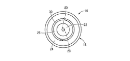
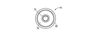
- FIG. 2 is a bottom view of the needleless connector shown in FIG. 1.
- FIG. 2 is a plan view of the needleless connector shown in FIG. 1.
- the front view of the needleless connector shown in FIG. FIG. 5 is a VV cross-sectional view of FIG. 3.
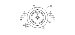
- FIG. 7 is a plan view of the base housing shown in FIG. 6. VIII-VIII sectional drawing of FIG. IX-IX sectional view of FIG.
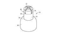
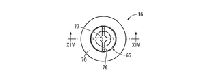
- the perspective view of the hollow elastic body which comprises the needleless connector shown by FIG.
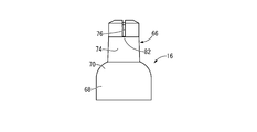
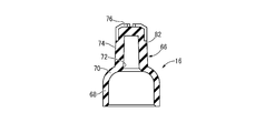
- FIG. 12 The front view of the hollow elastic body shown by FIG. FIG. 12 is a cross-sectional view taken along line XIV-XIV in FIG. 11. It is a longitudinal cross-sectional view which shows the needleless connector shown by FIG. 1, Comprising: The figure which shows the communication state of a chemical
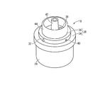
- the needleless connector 10 has a structure in which a disc valve 14 as an elastic valve body and a hollow elastic body 16 are incorporated in a housing 12.
- the vertical direction means the vertical direction in FIG. 5 in principle.
- the upper side in FIG. 5 is referred to as “the inlet side of the chemical liquid channel 80”
- the lower side in FIG. 5 is referred to as “the outlet side of the chemical channel 80”.
- the housing 12 includes a base housing 18 and a cover housing 20 as an accommodating portion.
- the base housing 18 is an integrally molded product of synthetic resin material, and a cylindrical portion 22 and a peripheral wall portion 24 each having a substantially cylindrical shape are predetermined in the radial direction.
- the cylindrical portion 22 and the peripheral wall portion 24 are connected to each other by a substantially disc-shaped lid portion 26 at the upper end portion.
- the cylindrical portion 22 has a substantially cylindrical shape with a small diameter, and is configured with a luer taper whose outer peripheral surface gradually decreases in diameter downward. Further, the center hole 28 of the cylindrical portion 22 is linearly provided in the vertical direction and opens to the lower surface of the cylindrical portion 22, and the upper end portion reaches the lid portion 26.
- the peripheral wall portion 24 has a substantially cylindrical shape larger in diameter than the cylindrical portion 22 and is disposed so as to surround the outer peripheral side with a predetermined distance from the cylindrical portion 22.
- a thread 30 is formed on the peripheral wall portion 24 so as to protrude on the inner peripheral surface.
- an intravascular indwelling catheter (not shown) is connected to the proximal end opening of the cylindrical portion 22 of the base housing 18.
- the tubular portion 22 and the peripheral wall portion 24 constitute a female luer lock structure, and an intravascular catheter (not shown) can be reliably connected and held.
- the lid portion 26 has a substantially disk shape, and is provided with a step surface 32 at an intermediate portion in the axial direction, and a large diameter portion 34 having a larger diameter than the peripheral wall portion 24 below the step surface 32.
- the upper side of the step surface 32 is a small diameter portion 36.
- the cylindrical portion 22 protrudes downward from the central portion of the large diameter portion 34, and the peripheral wall portion 24 protrudes downward from the outer peripheral portion of the large diameter portion 34.
- the lid portion 26 of the present embodiment is provided integrally with the housing 12 (base housing 18).
- the open passage 38 is a small-diameter circular hole, as shown in FIGS. 7 and 8, and has one end opening on the upper surface of the small-diameter portion 36 and bending and extending in the middle. The other end is open to the outer peripheral surface of the large diameter portion 34.
- the small diameter portion 36 of the lid portion 26 is formed with a communication hole 40 penetrating in the direction perpendicular to the axis, and both end portions thereof open to the outer peripheral surface of the small diameter portion 36.
- the central portion in the length direction communicates with the upper end portion of the center hole 28 formed in the cylindrical portion 22.
- the communication hole 40, the center hole 28, and the open passage 38 are provided independently without communicating with each other.
- a guide protrusion 42 that protrudes upward is integrally formed at a central portion in the radial direction of the small diameter portion 36 in the lid portion 26.
- the guide protrusion 42 has a small-diameter, substantially bottomed cylindrical shape that opens upward, and has a tapered shape with an outer peripheral surface that gradually decreases in diameter toward the upper side.
- a deformation restraining portion 44 that protrudes upward is integrally formed at a radially intermediate portion of the small diameter portion 36 in the lid portion 26.
- the deformation restricting portion 44 has a substantially cylindrical shape larger in diameter than the guide protrusion 42 and is provided on the outer peripheral side of the guide protrusion 42 at a predetermined distance.
- the outer peripheral corner portion of the protruding tip portion is chamfered, and the outer diameter of the protruding tip portion gradually decreases toward the tip side.
- the cover housing 20 has a substantially cylindrical shape as a whole, and a step portion 46 is formed at an intermediate portion in the axial direction, and a cover body 48 having a large diameter is formed below the step portion 46. At the same time, a connection port portion 50 having a small diameter is formed above the step portion 46. Furthermore, the outer peripheral surface of the upper part of the cover main body 48 has a tapered shape that gradually decreases in diameter upward. Moreover, the connection port part 50 comprises the male luer lock by forming the screw thread 52 so that it may protrude on an outer peripheral surface.
- the inner peripheral surface of the cover housing 20 has a shape that substantially corresponds to the outer peripheral surface of the hollow elastic body 16 described later.
- a lower communication groove 54 as a concave groove is formed in the cover body 48 of the cover housing 20.
- the lower communication groove 54 is a groove opened on the inner peripheral surface of the cover main body 48, is formed with a substantially constant depth dimension, and extends in the vertical direction.
- four lower communication grooves 54 are formed at equal intervals on the circumference, but the number of lower communication grooves 54 is not particularly limited.
- the base housing 18 is disposed so as to cover the lower opening of the cover housing 20, and the lower end surface of the cover housing 20 is overlapped with the large diameter portion 34 of the base housing 18, and adhesion, welding, or screws are used.
- the housing 12 is formed by being fixed to each other by means such as fastening.
- a housing space 56 is formed in the housing 12 using an inner peripheral region of the cover housing 20, and the housing space 56 opens upward through the upper opening of the cover housing 20 and communicates with the external space. In addition, it communicates with the external space below through the communication hole 40 and the center hole 28 of the base housing 18.
- Two of the four lower communication grooves 54 are positioned in the circumferential direction with the communication hole 40, and the lower communication groove 54 is communicated with the communication hole 40 at the lower end.
- an annular groove is formed so that the lower end portions of the lower communication groove 54 communicate with each other, and the lower communication groove 54 communicates with the communication hole 40 via this annular groove, the base Positioning of the housing 18 and the cover housing 20 in the circumferential direction can be made unnecessary.
- a disc valve 14 is disposed at the upper end opening of the connection port 50 of the housing 12 (cover housing 20).
- the disk valve 14 is formed of a rubber elastic body having a substantially disk shape, and includes a slit 58 extending in one radial direction and penetrating in the thickness direction as shown in FIGS. ing. The disc valve 14 is inserted and held in the upper opening of the cover housing 20.
- the hollow elastic body 16 is accommodated in the accommodation space 56 provided below the disc valve 14 and is disposed on the inner peripheral side of the cover housing 20.
- the hollow elastic body 16 is formed of an elastic material, and has a bottomed cylindrical shape that opens in the downward direction as shown in FIGS. 10 to 14, and has a center of its bottom wall (70). It is an integrally formed product integrally provided with a central protrusion 66 protruding upward from the portion.
- the hollow elastic body 16 is formed of an elastic material such as silicone rubber, and has a peripheral wall 68 and a bottom wall 70 that are integrally formed.
- the peripheral wall 68 has a substantially cylindrical shape
- the bottom wall 70 has a tapered shape that protrudes upward while inclining from the upper end of the peripheral wall 68 toward the inner peripheral side.
- a circular guide hole 72 penetrating in the thickness direction (vertical direction) is formed in the central portion of the bottom wall 70 in the radial direction, and the diameter of the guide hole 72 is a guide protrusion provided in the base housing 18.
- the guide protrusion 42 can be inserted by making it equal to or larger than the maximum outer diameter of the portion 42.
- the bottom wall 70 of the present embodiment has a curved shape in which the inclination angle with respect to the axial direction gradually increases upward in the longitudinal section.
- the central protrusion 66 has a substantially bottomed cylindrical shape that is open in the downward direction and is integrally formed with the hollow elastic body 16 by an elastic material, so that a guide hole in the bottom wall 70 of the hollow elastic body 16 is formed. Projecting upward from the peripheral edge of the opening 72.
- the hollow elastic body 16 is formed as an integrally molded product including the central protrusion 66 and integrally formed of an elastic material, thereby reducing the number of parts and simplifying the structure.
- the central protrusion 66 is thicker than the bottom wall 70 and the peripheral wall 68 of the hollow elastic body 16, and the pushing force at the male luer 86 described later is exerted on the central protrusion 66.
- the deformation of the bottom wall 70 occurs preferentially over the deformation of the central protrusion 66.
- peripheral wall portion of the central protrusion 66 has a tapered shape that gradually becomes larger in diameter toward the base end side (lower side), and the outer peripheral surface of the central protrusion 66 is below the upper communication groove 76 described later. Is formed of a tapered surface 74 having a smaller diameter toward the protruding tip side. Further, the inner peripheral region of the central protrusion 66 has a tapered hole shape that gradually increases in diameter downward, and opens downward through the guide hole 72 of the hollow elastic body 16, and in this embodiment, the guide hole 72. Part of.
- an upper communication groove 76 is formed at the upper end portion of the central protrusion 66.
- the upper communication groove 76 opens to the upper surface of the central protrusion 66 and has a cross shape extending in two radial directions to reach the outer peripheral end (see FIG. 11), and from the outer peripheral end toward the lower side in the axial direction. It extends linearly and opens on the outer peripheral surface of the upper end portion of the central protrusion 66 (see FIG. 13).
- a circular recess 77 is formed in the central portion of the upper surface of the central protrusion 66 in the radial direction, and the recess 77 communicates with the upper communication groove 76.
- the hollow elastic body 16 having such a structure is accommodated in the accommodation space 56 of the housing 12. That is, the hollow elastic body 16 is disposed between the axially opposed surfaces of the base housing 18 and the disk valve 14, and the downward opening is covered with the lid portion 26 of the base housing 18. Further, a deformation allowable space 78 is formed between the hollow elastic body 16 and the lid portion 26 of the base housing 18, and the deformation allowable space 78 communicates with the external space through the open passage 38 of the lid portion 26. Yes.
- the deformation restraining portion 44 of the base housing 18 is inserted from the lower opening of the hollow elastic body 16 and overlapped with the inner peripheral surface of the peripheral wall 68, and the peripheral wall 68 of the hollow elastic body 16 is connected to the deformation restraining portion 44. It is sandwiched between the cover housings 20.
- the guide protrusion 42 of the base housing 18 is positioned below the bottom surface of the bottom wall 70 of the hollow elastic body 16, and It protrudes toward the central portion, is positioned in a direction perpendicular to the axis with respect to the guide hole 72 of the hollow elastic body 16, and is spaced apart downward.
- the hollow elastic body 16 is disposed in the accommodation space 56, the outer peripheral surface of the hollow elastic body 16 is in close contact with the inner peripheral surface of the cover housing 20 without any gaps or leakage of a chemical solution or the like. They are stacked with a small gap so that the residue does not become a problem. Accordingly, the opening of the lower communication groove 54 formed in the cover housing 20 is covered with the hollow elastic body 16, and a tunnel-like flow path is formed between the cover housing 20 and the hollow elastic body 16.
- the tunnel-shaped flow path communicates with the communication hole 40 and the center hole 28 of the base housing 18, so that at least a part (a part constituted by the lower communication groove 54) is formed between the housing 12 and the hollow elastic body 16.
- An extending chemical liquid flow path 80 is formed.
- the outer peripheral surface of the hollow elastic body 16 is overlapped with the inner peripheral surface of the cover housing 20, so that the opening of the upper communication groove 76 formed in the central protrusion 66 is covered with the cover housing 20.
- a tunnel-like flow path is formed between the housing 20 and the hollow elastic body 16.
- the upper end portion of the lower communication groove 54 does not reach the lower end portion of the upper communication groove 76 and is spaced apart downward, and a valve formed by the lower wall portion of the upper communication groove 76 in the central protrusion 66.
- the seat portion 82 is in contact with the upper wall portion of the lower communication groove 54 in the cover housing 20.
- the lower communication groove 54 and the upper communication groove 76 are separated by the valve seat portion 82, and the chemical flow path 80 is blocked by the valve seat section 82 at an intermediate portion in the flow path length direction.
- the needleless connector 10 having such a structure is used with a catheter or the like connected to the proximal end opening of the chemical liquid flow path 80 as described above. Then, as shown in FIG. 15, a male luer 86 such as a syringe 84 is inserted from above through the connection port 50 of the housing 12, so that the slit 58 of the disc valve 14 is expanded. Is done.
- the male luer 86 of the syringe 84 shown in FIG. 15 has a male luer lock structure so that the connection state with respect to the connection port 50 of the cover housing 20 is reliably maintained.
- the male luer 86 may have not only a luer lock structure that is fixed by screws, but also a luer slip structure that is inserted and fixed.
- the male luer 86 when the male luer 86 is inserted into the slit 58, the pushing force of the male luer 86 is exerted on the hollow elastic body 16, and the upper and lower communication grooves 76, 54 formed by the valve seat portion 82. By releasing the blocking, the male luer 86 is brought into communication with the chemical liquid flow path 80.
- the male luer 86 inserted through the slit 58 of the disc valve 14 pushes the central protrusion 66 of the hollow elastic body 16 downward, so that the central protrusion 66 is displaced downward,
- the contact between the valve seat 82 of the central protrusion 66 and the inner peripheral surface of the housing 12 is released.
- the lower communication groove 54 and the upper communication groove 76 are communicated with each other, and the male luer 86 is communicated with the chemical liquid flow path 80.
- the chemical liquid flow path 80 is provided so as to penetrate the housing 12 in the vertical direction, which is the length direction, and the inlet thereof is a slit 58 of the disc valve 14 disposed at the upper end portion of the housing 12.
- the outlet is a central hole 28 of the cylindrical portion 22 provided at the lower end portion of the housing 12.
- the central protrusion 66 is pushed downward by the male luer 86, the inner peripheral portion of the bottom wall 70 of the hollow elastic body 16 is pushed downward.
- the hollow elastic body 16 is elastically deformed so that the inner peripheral portion of the bottom wall 70 enters the inner peripheral side of the peripheral wall 68 (within the deformation allowable space 78).
- the bottom wall 70 of the hollow elastic body 16 is separated from the inner peripheral surface of the cover housing 20, and the volume of the chemical liquid flow path 80 formed between the housing 12 and the hollow elastic body 16 is positively increased. It will be.
- the volume reduction corresponding to the shape restoration of the hollow elastic body 16 generates a positive pressure (positive pressure) in the chemical liquid flow path 80 of the needleless connector 10. The effect of preventing the backflow of blood and the like is exhibited.
- the accommodation space 56 is divided into the inner peripheral deformation allowable space 78 and the outer peripheral chemical liquid flow channel 80 with the hollow elastic body 16 in between, and the pushing force of the male luer 86 acts to be hollow.
- the elastic body 16 is elastically deformed, the volume ratio between the deformation allowable space 78 and the chemical liquid flow path 80 is changed.
- the chemical liquid flow path 80 is in communication, the bottom wall 70 enters the peripheral wall 68, whereby the volume of the deformation allowable space 78 decreases and the volume of the chemical liquid flow path 80 increases.
- the bottom wall 70 protrudes from the inside of the peripheral wall 68 to increase the volume of the deformation allowable space 78 and decrease the volume of the chemical liquid flow path 80. Positive pressure is generated in the.
- the peripheral wall 68 of the hollow elastic body 16 is sandwiched between the cover housing 20 and the deformation restraining portion 44 of the base housing 18 to restrict deformation. Therefore, when the central protrusion 66 is pushed by the male luer 86, the hollow elastic body 16 does not bulge outward and is stably elastically deformed so that the bottom wall 70 enters the peripheral wall 68. Therefore, the chemical liquid flow path 80 is switched to the communication state with high reliability, and the backflow preventing effect using the volume change of the chemical liquid flow path 80 is reliably exhibited.
- the outer peripheral surface of the hollow elastic body 16 has a shape substantially corresponding to the inner peripheral surface of the cover housing 20, and the upper and lower communication grooves 76 are formed between the outer peripheral surface of the hollow elastic body 16 and the inner peripheral surface of the cover housing 20. , 54 are overlapped with no gap or through a very small gap at a portion outside 54. Therefore, by extracting the male luer 86, the hollow elastic body 16 returns to the initial shape from the deformed state, so that the chemical solution between the cover housing 20 and the hollow elastic body 16 is pushed out to the outlet side without remaining, It is possible to reliably deliver a target amount of chemical solution or the like to the outlet side.
- the upper and lower communication grooves 76 and 54 constituting the chemical liquid flow path 80 extend in the vertical direction over a wide range excluding a part of the upper communication groove 76, the chemical liquid and the like in the chemical liquid flow path 80 can be obtained. It is automatically guided to the outlet side by the action of gravity, and discharged from the outlet (center hole 28) to the outside. As described above, the remaining of the chemical liquid in the chemical liquid flow path 80 is also prevented by the shape (extending direction) of the chemical liquid flow path 80.
- the central protrusion 66 is pushed down by the male luer 86 so that the guide protrusion 42 provided on the base housing 18 is inserted into the guide hole 72 formed in the bottom wall 70 of the hollow elastic body 16. It has become. This prevents distortion deformation such as deformation of the central projection 66 so that it falls down, and the hollow elastic body 16 is stably elastically deformed in the intended deformation mode. Both the switching to and the action of preventing the backflow of blood or the like can be realized stably.
- the guide hole 72 has a tapered shape in which the diameter increases toward the opening side
- the guide protrusion 42 has a tapered shape in which the diameter decreases toward the protruding tip side.
- the chemical flow path 80 is also brought about when the valve seat portion 82 of the hollow elastic body 16 abuts on the inner peripheral surface of the housing 12. Is to be blocked. Since the double valve means is provided in this way, leakage of the chemical liquid or blood to the inlet side is effectively prevented.
- the shape of the hollow elastic body is not limitedly interpreted by the specific shape shown in the embodiment.
- the shape of the bottom wall has a curved cross section as shown in the above embodiment, a flat plate shape extending in a direction perpendicular to the axis, or a tapered shape inclined at a substantially constant inclination angle. Etc.
- valve seat portion can be provided not on the central protrusion 66 but on the bottom wall 70 or may not be provided. It is also possible to improve the blocking performance of the chemical liquid flow path 80 by providing a plurality of valve seat portions.
- the central protrusion is not limited to the hollow shape shown in the embodiment, and may be a solid column.
- the guide protrusion 42 provided on the base housing 18 in the above embodiment has a small protrusion height corresponding to the thickness of the bottom wall 70 of the hollow elastic body 16 or is omitted. Is done.
- the thickness of the bottom wall of the hollow elastic body may be smaller than the thickness of the peripheral wall. In this way, since the hollow elastic body is easily elastically deformed at the bottom wall portion, when the male luer is inserted, elastic deformation that enters the inner peripheral side of the peripheral wall of the bottom wall is more reliably realized.
- the lid portion 26 is provided integrally with the base housing 18, but the lid portion may be formed of a member separate from the housing.
- the central protrusion may be formed separately from the hollow elastic body, and in this case, the central protrusion and the hollow elastic body can be fixed later by means such as adhesion or welding.
- the central protrusion is formed of an elastic material, and for example, it can be formed of a hard synthetic resin or the like.
- a concave groove formed on one or both of the inner peripheral surface of the cover housing 20 and the outer peripheral surfaces of the hollow elastic body 16 and the central protrusion 66 is covered. Accordingly, the chemical liquid flow path 80 can be formed.
- the hollow elastic body is formed of silicone rubber, but any material can be used as long as it conforms to the gist of the present invention.
- silicone rubber, synthetic rubber, natural rubber, thermoplastic elastomer and the like are used.
- a hollow elastic body is a structure by which a center protrusion is pushed below by a male luer, for example, providing a pushing element separate from them between a male luer and a hollow elastic body
- a configuration in which the central protrusion of the hollow elastic body is pressed and deformed by the pusher which is movably disposed in the housing and moved by the male luer may be employed.
- 10 Needleless connector
- 12 Housing
- 14 Disc valve (elastic valve body)
- 16 Hollow elastic body
- 20 Cover housing (accommodating part)
- 26 Cover part
- 28 Center hole (exit)
- 38 Open passage
- 42 guide protrusion
- 44 deformation restraint
- 54 lower communication groove (concave groove)
- 58 slit (inlet)
- 66 central protrusion
- 68 peripheral wall
- 70 bottom wall
- 72 guide Hole:
- 74 Tapered surface
- 76 Upper communication groove
- 78 Deformable space
- 80 Chemical liquid flow path
- 82 Valve seat
- 86 Male lure
Abstract
Description
Claims (8)
- ハウジングの長さ方向の一方側と他方側に薬液流路の入口と出口が設けられていると共に、該ハウジングにおける該薬液流路の該入口にはスリットを有する弾性弁体が取り付けられており、該薬液流路の該入口から挿し入れられる雄ルアーで該弾性弁体を変形させて該スリットを開くことで該薬液流路が遮断状態から連通状態に切り換えられるニードルレスコネクターにおいて、
前記ハウジングに形成された収容部に対して前記薬液流路の前記出口側に向かって開口する有底筒状の中空弾性体が収容配置されていると共に、該中空弾性体の底壁の中央部分から該薬液流路の前記入口側に向かって突出する中央突部を設けて、前記雄ルアーの挿入により該中空弾性体の底壁が周壁内に入り込むように弾性変形されて、該中空弾性体の外面と該収容部の内面との間に形成された該薬液流路の容積が拡大されると共に、該雄ルアーが抜き取られて該中空弾性体の弾性変形が解除されることにより該薬液流路の容積が縮小されるようにしたことを特徴とするニードルレスコネクター。 - 前記中空弾性体が、前記中央突部を含んで弾性材で一体形成された一体成形品とされている請求項1に記載のニードルレスコネクター。
- 前記中空弾性体の開口を覆蓋する蓋部が設けられて、該蓋部と該中空弾性体の間に変形許容空間が形成されており、該変形許容空間を外部空間に連通する開放通路が該蓋部に形成されている請求項1又は2に記載のニードルレスコネクター。
- 前記蓋部には、前記変形許容空間内に突出して前記中空弾性体の前記周壁の内周面に重ね合わされる変形拘束部が設けられている請求項3に記載のニードルレスコネクター。
- 前記蓋部には、前記中空弾性体の底部中央に向かって突出するガイド突部が設けられていると共に、該中空弾性体の底部中央には該ガイド突部を挿し入れ可能なガイド穴が設けられている請求項3又は4の何れか1項に記載のニードルレスコネクター。
- 前記蓋部が前記ハウジングに一体で設けられている請求項3~5の何れか1項に記載のニードルレスコネクター。
- 前記中空弾性体の外周面には、前記薬液流路の前記入口側に向かって小径となるテーパ面が設けられていると共に、該テーパ面において前記ハウジングの前記収容部の内面への当接により該薬液流路を遮断する弁座部が設けられている請求項1~6の何れか1項に記載のニードルレスコネクター。
- 前記ハウジングの前記収容部の内面には、前記薬液流路の長さ方向に延びる凹溝が形成されている請求項1~7の何れか1項に記載のニードルレスコネクター。
Priority Applications (4)
| Application Number | Priority Date | Filing Date | Title |
|---|---|---|---|
| CN201280065126.6A CN104023786B (zh) | 2011-12-27 | 2012-12-27 | 无针连接器 |
| EP12862179.4A EP2799108B1 (en) | 2011-12-27 | 2012-12-27 | Needleless connector |
| JP2013551466A JP6102747B2 (ja) | 2011-12-27 | 2012-12-27 | ニードルレスコネクター |
| US14/366,387 US9238128B2 (en) | 2011-12-27 | 2012-12-27 | Needleless connector |
Applications Claiming Priority (2)
| Application Number | Priority Date | Filing Date | Title |
|---|---|---|---|
| JP2011284921 | 2011-12-27 | ||
| JP2011-284921 | 2011-12-27 |
Publications (1)
| Publication Number | Publication Date |
|---|---|
| WO2013099261A1 true WO2013099261A1 (ja) | 2013-07-04 |
Family
ID=48696792
Family Applications (1)
| Application Number | Title | Priority Date | Filing Date |
|---|---|---|---|
| PCT/JP2012/008371 WO2013099261A1 (ja) | 2011-12-27 | 2012-12-27 | ニードルレスコネクター |
Country Status (5)
| Country | Link |
|---|---|
| US (1) | US9238128B2 (ja) |
| EP (1) | EP2799108B1 (ja) |
| JP (1) | JP6102747B2 (ja) |
| CN (1) | CN104023786B (ja) |
| WO (1) | WO2013099261A1 (ja) |
Cited By (9)
| Publication number | Priority date | Publication date | Assignee | Title |
|---|---|---|---|---|
| EP2777757A1 (en) * | 2013-03-14 | 2014-09-17 | CareFusion 303, Inc. | Needleless connector with support member |
| US9144672B2 (en) | 2013-03-13 | 2015-09-29 | Carefusion 303, Inc. | Needleless connector with compressible valve |
| US9278205B2 (en) | 2013-03-13 | 2016-03-08 | Carefusion 303, Inc. | Collapsible valve with internal dimples |
| US9370651B2 (en) | 2013-03-13 | 2016-06-21 | Carefusion 303, Inc. | Needleless connector with reduced trapped volume |
| JP2016532476A (ja) * | 2013-10-09 | 2016-10-20 | アプター ステルミ エスアーエスAptar Stelmi Sas | 摺動可能なプランジャープラグ、およびそれを有するシリンジ装置 |
| JPWO2015145998A1 (ja) * | 2014-03-28 | 2017-04-13 | テルモ株式会社 | 医療用コネクタ |
| US10478607B2 (en) | 2004-08-09 | 2019-11-19 | Carefusion 303, Inc. | Connector for transferring fluid and method of use |
| TWI687245B (zh) * | 2019-09-17 | 2020-03-11 | 慈濟學校財團法人慈濟科技大學 | 輸液套管 |
| US10842984B2 (en) | 2004-08-09 | 2020-11-24 | Carefusion 303, Inc. | Connector for transferring fluid |
Families Citing this family (22)
| Publication number | Priority date | Publication date | Assignee | Title |
|---|---|---|---|---|
| CN101068592B (zh) | 2004-11-05 | 2010-12-08 | Icu医疗公司 | 具有高流动速率特征的医用连接器 |
| US9168366B2 (en) | 2008-12-19 | 2015-10-27 | Icu Medical, Inc. | Medical connector with closeable luer connector |
| US8454579B2 (en) | 2009-03-25 | 2013-06-04 | Icu Medical, Inc. | Medical connector with automatic valves and volume regulator |
| US8323249B2 (en) | 2009-08-14 | 2012-12-04 | The Regents Of The University Of Michigan | Integrated vascular delivery system |
| USD644731S1 (en) | 2010-03-23 | 2011-09-06 | Icu Medical, Inc. | Medical connector |
| US8758306B2 (en) | 2010-05-17 | 2014-06-24 | Icu Medical, Inc. | Medical connectors and methods of use |
| WO2011146772A1 (en) | 2010-05-19 | 2011-11-24 | Tangent Medical Technologies Llc | Safety needle system operable with a medical device |
| WO2011146769A2 (en) | 2010-05-19 | 2011-11-24 | Tangent Medical Technologies Llc | Integrated vascular delivery system |
| JP6553357B2 (ja) | 2011-09-09 | 2019-07-31 | アイシーユー・メディカル・インコーポレーテッド | 耐流体性嵌合インターフェースを備えた医療用コネクタ |
| EP2916905A4 (en) | 2012-11-12 | 2016-11-09 | Icu Medical Inc | MEDICAL CONNECTION |
| KR102263974B1 (ko) | 2013-03-15 | 2021-06-10 | 아이씨유 메디칼 인코퍼레이티드 | 의료용 커넥터 |
| EP2862587A1 (en) | 2013-10-15 | 2015-04-22 | Becton Dickinson France | Tip cap assembly for closing an injection system |
| JP7176834B2 (ja) | 2013-12-11 | 2022-11-22 | アイシーユー・メディカル・インコーポレーテッド | 逆止め弁 |
| AU2015214400B2 (en) | 2014-02-04 | 2019-10-03 | Icu Medical, Inc. | Self-priming systems and methods |
| JP6437528B2 (ja) * | 2014-03-28 | 2018-12-12 | テルモ株式会社 | コネクタ及び輸液セット |
| ES2699383T3 (es) * | 2014-07-08 | 2019-02-11 | Applied Med Resources | Cierre de instrumento altamente sensible |
| USD793551S1 (en) | 2014-12-03 | 2017-08-01 | Icu Medical, Inc. | Fluid manifold |
| USD786427S1 (en) | 2014-12-03 | 2017-05-09 | Icu Medical, Inc. | Fluid manifold |
| CN104645460B (zh) * | 2015-02-12 | 2018-01-26 | 昆山安卓精密模具有限公司 | 一种耐疲劳型无针接头 |
| CN108815698A (zh) * | 2018-07-06 | 2018-11-16 | 苏州鑫康道医疗科技有限公司 | 持续正压接头 |
| CN109010990A (zh) * | 2018-08-28 | 2018-12-18 | 河南曙光汇知康生物科技股份有限公司 | 一种新型输液无针接头 |
| CN108785848B (zh) * | 2018-09-07 | 2023-11-21 | 临沂市兴华医用器材有限公司 | 一种麻醉导管连接器 |
Citations (5)
| Publication number | Priority date | Publication date | Assignee | Title |
|---|---|---|---|---|
| JPH08168535A (ja) * | 1994-05-27 | 1996-07-02 | Ivac Corp | バイパス弁構造を備えた無針式注入サイト |
| US5730418A (en) | 1996-09-30 | 1998-03-24 | The Kipp Group | Minimum fluid displacement medical connector |
| JP2004275472A (ja) * | 2003-03-17 | 2004-10-07 | Nipro Corp | 医療用弁 |
| JP2006515220A (ja) | 2003-04-03 | 2006-05-25 | ビー.ブラウン メディカル,インコーポレイティド | 注射ポート弁 |
| US20080172003A1 (en) * | 2006-10-18 | 2008-07-17 | Michael Plishka | Luer activated device |
Family Cites Families (10)
| Publication number | Priority date | Publication date | Assignee | Title |
|---|---|---|---|---|
| US5509433A (en) * | 1993-10-13 | 1996-04-23 | Paradis; Joseph R. | Control of fluid flow |
| US5806831A (en) * | 1993-10-13 | 1998-09-15 | Paradis; Joseph R. | Control of fluid flow with internal cannula |
| US6183448B1 (en) | 1994-06-20 | 2001-02-06 | Bruno Franz P. Mayer | Needleless injection site |
| NZ336284A (en) | 1996-12-16 | 2001-05-25 | Icu Medical Inc | Positive flow valve for controlling flow between medical implement and catheter tip with seal increasing or decreasing in size when moved between two positions |
| US6050978A (en) * | 1997-05-09 | 2000-04-18 | Becton Dickinson And Company | Needleless valve connector |
| US6706022B1 (en) * | 1999-07-27 | 2004-03-16 | Alaris Medical Systems, Inc. | Needleless medical connector with expandable valve mechanism |
| CA2459695A1 (en) * | 2001-08-22 | 2003-03-06 | Brian L. Newton | Medical valve with expandable seal member |
| US20030172003A1 (en) * | 2002-03-06 | 2003-09-11 | Holbrook Richard M. | Method and system for designing configurable furniture product |
| EP2049194A1 (en) * | 2006-08-11 | 2009-04-22 | Nypro Inc. | Medical valve with expandable member |
| TW201032852A (en) * | 2009-03-11 | 2010-09-16 | Shu-Fang Huang | Needle-free injection structure |
-
2012
- 2012-12-27 US US14/366,387 patent/US9238128B2/en active Active
- 2012-12-27 CN CN201280065126.6A patent/CN104023786B/zh active Active
- 2012-12-27 EP EP12862179.4A patent/EP2799108B1/en active Active
- 2012-12-27 WO PCT/JP2012/008371 patent/WO2013099261A1/ja active Application Filing
- 2012-12-27 JP JP2013551466A patent/JP6102747B2/ja active Active
Patent Citations (5)
| Publication number | Priority date | Publication date | Assignee | Title |
|---|---|---|---|---|
| JPH08168535A (ja) * | 1994-05-27 | 1996-07-02 | Ivac Corp | バイパス弁構造を備えた無針式注入サイト |
| US5730418A (en) | 1996-09-30 | 1998-03-24 | The Kipp Group | Minimum fluid displacement medical connector |
| JP2004275472A (ja) * | 2003-03-17 | 2004-10-07 | Nipro Corp | 医療用弁 |
| JP2006515220A (ja) | 2003-04-03 | 2006-05-25 | ビー.ブラウン メディカル,インコーポレイティド | 注射ポート弁 |
| US20080172003A1 (en) * | 2006-10-18 | 2008-07-17 | Michael Plishka | Luer activated device |
Non-Patent Citations (1)
| Title |
|---|
| See also references of EP2799108A4 |
Cited By (27)
| Publication number | Priority date | Publication date | Assignee | Title |
|---|---|---|---|---|
| US10940306B2 (en) | 2004-08-09 | 2021-03-09 | Carefusion 303, Inc. | Connector for transferring fluid and method of use |
| US10842984B2 (en) | 2004-08-09 | 2020-11-24 | Carefusion 303, Inc. | Connector for transferring fluid |
| US10478607B2 (en) | 2004-08-09 | 2019-11-19 | Carefusion 303, Inc. | Connector for transferring fluid and method of use |
| US10016588B2 (en) | 2013-03-13 | 2018-07-10 | Carefusion 303, Inc. | Needleless connector with compressible valve |
| US11602626B2 (en) | 2013-03-13 | 2023-03-14 | Carefusion 303, Inc. | Needleless connector with compressible valve |
| US9144672B2 (en) | 2013-03-13 | 2015-09-29 | Carefusion 303, Inc. | Needleless connector with compressible valve |
| US9278205B2 (en) | 2013-03-13 | 2016-03-08 | Carefusion 303, Inc. | Collapsible valve with internal dimples |
| US9370651B2 (en) | 2013-03-13 | 2016-06-21 | Carefusion 303, Inc. | Needleless connector with reduced trapped volume |
| US10653879B2 (en) | 2013-03-13 | 2020-05-19 | Carefusion 303, Inc. | Needleless connector with compressible valve |
| US9694171B2 (en) | 2013-03-13 | 2017-07-04 | Carefusion 303, Inc. | Collapsible valve with internal dimples |
| US10322276B2 (en) | 2013-03-13 | 2019-06-18 | Carefusion 303, Inc. | Collapsible valve with internal dimples |
| JP2020171849A (ja) * | 2013-03-14 | 2020-10-22 | ケアフュージョン 303、インコーポレイテッド | 支持部材を備える無針コネクタ |
| EP2777757A1 (en) * | 2013-03-14 | 2014-09-17 | CareFusion 303, Inc. | Needleless connector with support member |
| JP2019030769A (ja) * | 2013-03-14 | 2019-02-28 | ケアフュージョン 303、インコーポレイテッド | 支持部材を備える無針コネクタ |
| AU2014228543B2 (en) * | 2013-03-14 | 2018-05-31 | Carefusion 303, Inc. | Needleless connector with support member |
| EP3199199A1 (en) * | 2013-03-14 | 2017-08-02 | CareFusion 303, Inc. | Needleless connector with support member |
| EP4218896A3 (en) * | 2013-03-14 | 2024-01-24 | CareFusion 303, Inc. | Needleless connector with support member |
| US11730944B2 (en) | 2013-03-14 | 2023-08-22 | Carefusion 303, Inc. | Needleless connector with support member |
| EP3335757A1 (en) * | 2013-03-14 | 2018-06-20 | Carefusion 303 Inc. | Needleless connector with support member |
| WO2014143530A1 (en) * | 2013-03-14 | 2014-09-18 | Carefusion 303, Inc. | Needleless connector with support member |
| US9089682B2 (en) | 2013-03-14 | 2015-07-28 | Carefusion 303, Inc. | Needleless connector with support member |
| US11033726B2 (en) | 2013-03-14 | 2021-06-15 | Carefusion 303, Inc. | Needleless connector with support member |
| AU2020210179B2 (en) * | 2013-03-14 | 2021-08-26 | Carefusion 303, Inc. | Needleless connector with support member |
| JP7033631B2 (ja) | 2013-03-14 | 2022-03-10 | ケアフュージョン 303、インコーポレイテッド | 支持部材を備える無針コネクタ |
| JP2016532476A (ja) * | 2013-10-09 | 2016-10-20 | アプター ステルミ エスアーエスAptar Stelmi Sas | 摺動可能なプランジャープラグ、およびそれを有するシリンジ装置 |
| JPWO2015145998A1 (ja) * | 2014-03-28 | 2017-04-13 | テルモ株式会社 | 医療用コネクタ |
| TWI687245B (zh) * | 2019-09-17 | 2020-03-11 | 慈濟學校財團法人慈濟科技大學 | 輸液套管 |
Also Published As
| Publication number | Publication date |
|---|---|
| EP2799108B1 (en) | 2019-05-15 |
| JP6102747B2 (ja) | 2017-03-29 |
| CN104023786A (zh) | 2014-09-03 |
| JPWO2013099261A1 (ja) | 2015-04-30 |
| CN104023786B (zh) | 2017-03-22 |
| EP2799108A4 (en) | 2015-06-03 |
| US20140316350A1 (en) | 2014-10-23 |
| EP2799108A1 (en) | 2014-11-05 |
| US9238128B2 (en) | 2016-01-19 |
Similar Documents
| Publication | Publication Date | Title |
|---|---|---|
| JP6102747B2 (ja) | ニードルレスコネクター | |
| US8511638B2 (en) | Neonatal Luer-activated medical connector | |
| EP2331185B1 (en) | Luer activated medical connector having a low priming volume | |
| AU2005314266B2 (en) | Self-sealing male luer connector with multiple seals | |
| ES2429563T3 (es) | Conector de válvula de fluido | |
| EP2086623B1 (en) | Medical connector | |
| US7867204B2 (en) | Needleless access port valves | |
| JP2024028615A (ja) | 支持部材を備える無針コネクタ | |
| KR20120003879A (ko) | 무바늘 억세스 장치로 사용하기 위한 밀폐식 숫 루어 장치 | |
| JP2012501743A5 (ja) | ||
| JP2011172615A (ja) | 医療用コネクタ | |
| JP6670437B2 (ja) | ニードルレスコネクター | |
| JP6016052B2 (ja) | ニードルレスコネクター | |
| JP2016202937A (ja) | ニードルレスコネクター | |
| JP2024516559A (ja) | 非対称の弁設計と主シール支持体とを有する逆止弁を有する無針コネクタ |
Legal Events
| Date | Code | Title | Description |
|---|---|---|---|
| 121 | Ep: the epo has been informed by wipo that ep was designated in this application |
Ref document number: 12862179 Country of ref document: EP Kind code of ref document: A1 |
|
| ENP | Entry into the national phase |
Ref document number: 2013551466 Country of ref document: JP Kind code of ref document: A |
|
| WWE | Wipo information: entry into national phase |
Ref document number: 14366387 Country of ref document: US |
|
| WWE | Wipo information: entry into national phase |
Ref document number: 2012862179 Country of ref document: EP |
|
| NENP | Non-entry into the national phase |
Ref country code: DE |