WO2013099045A1 - 画像表示装置および画像表示方法 - Google Patents
画像表示装置および画像表示方法 Download PDFInfo
- Publication number
- WO2013099045A1 WO2013099045A1 PCT/JP2012/003487 JP2012003487W WO2013099045A1 WO 2013099045 A1 WO2013099045 A1 WO 2013099045A1 JP 2012003487 W JP2012003487 W JP 2012003487W WO 2013099045 A1 WO2013099045 A1 WO 2013099045A1
- Authority
- WO
- WIPO (PCT)
- Prior art keywords
- image
- display
- well
- images
- image processing
- Prior art date
- Legal status (The legal status is an assumption and is not a legal conclusion. Google has not performed a legal analysis and makes no representation as to the accuracy of the status listed.)
- Ceased
Links
Images


Classifications
-
- G—PHYSICS
- G06—COMPUTING OR CALCULATING; COUNTING
- G06T—IMAGE DATA PROCESSING OR GENERATION, IN GENERAL
- G06T7/00—Image analysis
- G06T7/0002—Inspection of images, e.g. flaw detection
- G06T7/0012—Biomedical image inspection
-
- G—PHYSICS
- G06—COMPUTING OR CALCULATING; COUNTING
- G06V—IMAGE OR VIDEO RECOGNITION OR UNDERSTANDING
- G06V20/00—Scenes; Scene-specific elements
- G06V20/60—Type of objects
- G06V20/69—Microscopic objects, e.g. biological cells or cellular parts
- G06V20/695—Preprocessing, e.g. image segmentation
-
- G—PHYSICS
- G09—EDUCATION; CRYPTOGRAPHY; DISPLAY; ADVERTISING; SEALS
- G09G—ARRANGEMENTS OR CIRCUITS FOR CONTROL OF INDICATING DEVICES USING STATIC MEANS TO PRESENT VARIABLE INFORMATION
- G09G5/00—Control arrangements or circuits for visual indicators common to cathode-ray tube indicators and other visual indicators
- G09G5/22—Control arrangements or circuits for visual indicators common to cathode-ray tube indicators and other visual indicators characterised by the display of characters or indicia using display control signals derived from coded signals representing the characters or indicia, e.g. with a character-code memory
- G09G5/30—Control of display attribute
-
- G—PHYSICS
- G02—OPTICS
- G02B—OPTICAL ELEMENTS, SYSTEMS OR APPARATUS
- G02B21/00—Microscopes
- G02B21/34—Microscope slides, e.g. mounting specimens on microscope slides
-
- G—PHYSICS
- G06—COMPUTING OR CALCULATING; COUNTING
- G06T—IMAGE DATA PROCESSING OR GENERATION, IN GENERAL
- G06T2200/00—Indexing scheme for image data processing or generation, in general
- G06T2200/24—Indexing scheme for image data processing or generation, in general involving graphical user interfaces [GUIs]
-
- G—PHYSICS
- G06—COMPUTING OR CALCULATING; COUNTING
- G06T—IMAGE DATA PROCESSING OR GENERATION, IN GENERAL
- G06T2207/00—Indexing scheme for image analysis or image enhancement
- G06T2207/10—Image acquisition modality
- G06T2207/10056—Microscopic image
-
- G—PHYSICS
- G06—COMPUTING OR CALCULATING; COUNTING
- G06T—IMAGE DATA PROCESSING OR GENERATION, IN GENERAL
- G06T2207/00—Indexing scheme for image analysis or image enhancement
- G06T2207/30—Subject of image; Context of image processing
- G06T2207/30004—Biomedical image processing
- G06T2207/30024—Cell structures in vitro; Tissue sections in vitro
-
- G—PHYSICS
- G06—COMPUTING OR CALCULATING; COUNTING
- G06T—IMAGE DATA PROCESSING OR GENERATION, IN GENERAL
- G06T2207/00—Indexing scheme for image analysis or image enhancement
- G06T2207/30—Subject of image; Context of image processing
- G06T2207/30004—Biomedical image processing
- G06T2207/30072—Microarray; Biochip, DNA array; Well plate
Definitions
- the present invention relates to an image display device and an image display method for displaying an image reflecting a result of performing predetermined image processing on an image obtained by imaging a recess of a sample holding plate.
- a cell (culture medium) or culture medium is injected into each well of a plate-like instrument provided with a large number of depressions, also called wells, and cultured here Etc. are performed.
- a plate-like instrument provided with a large number of depressions, also called wells, and cultured here Etc.
- Such an instrument is called, for example, a microplate or a microtiter plate.
- a technique for example a method of fluorescently emitting a specific molecule by pretreatment of a sample or use of a reagent has been conventionally performed.
- a technique for analyzing and displaying an original image using an image processing technique has been studied. For example, in the image processing system described in Patent Document 1, a plurality of living cells are taken as observation samples, the image is captured, and an image colored according to the feature amount is displayed for a cell region recognized by analyzing the image. It is configured to let you.
- the present invention has been made in view of the above problems, and in the technology for displaying an image obtained by imaging the recess of the sample holding plate, an image display device or an image for displaying an image that can meet the user's request as described above It is intended to provide a display method.
- One aspect of the present invention is an image display device that displays an image obtained by imaging the recess of a sample holding plate in which a plurality of recesses for holding a sample are arranged.
- An image for display in which a raw material image obtained by performing image processing for giving visual information according to the content of the original image to the original image obtained by imaging the depression is provided, and a plurality of different raw material images are arranged Image processing means for generating the image and display means for displaying the display image.
- an image display method for displaying an image obtained by imaging the depression of a sample holding plate in which a plurality of depressions for holding a sample are arranged.
- the display image is (1) a set of a plurality of material images obtained by performing the same image processing on each of the original images corresponding to the different recesses, and (2) the same.
- the original image includes at least one of a plurality of sets of the material images obtained by performing different image processing on the original image.
- means for giving visual information to the material image for example, color coding, painting, changing brightness, emphasizing contours, adding a frame or pointer, adding text information, or a combination thereof It is possible to use.
- a display image corresponding to an instruction input from a user regarding at least one of selection of a material image and selection of contents of image processing may be created.
- the image processing unit includes a specific part detection unit that detects a specific part having specific optical characteristics in the original image, and a feature that calculates a feature amount of the detected specific part. You may make it provide the amount calculation part and the visual information provision part which provides the visual information according to the value of the calculated feature-value to an original image. In this way, it is possible to present to the user a display image that makes it possible to easily distinguish a part (specific part) having a specific feature included in the image from other parts.
- the visual information giving unit may give visual information corresponding to the value of the feature amount calculated for the specific part at a position corresponding to the specific part in the original image, for example.
- the user can easily grasp the distribution status of the specific part, and can easily compare the distribution status among a plurality of material images.
- the display image may be created so as to include a plurality of material images each provided with visual information based on different feature amounts with respect to the same original image. In this way, since the material images obtained by processing one sample from different viewpoints are displayed at the same time, the user can observe the sample more efficiently.
- a display image may be created in which a plurality of material images corresponding to different recesses are arranged in correspondence with the arrangement order of the recesses on the sample holding plate. In this way, the user can easily grasp the relationship between displayed material images, and can efficiently perform comparative observation.
- the display magnification of the material image in the display image can be changed and set, and the visual information added to the material image may be different according to the set display magnification. This makes it possible to present a display image that is easier for the user to visually recognize.
- a display image including a plurality of material images obtained by performing different image processing on the same partial region in the same original image may be created.
- the user may desire to display only a partial region of the original image. In such a case, if a plurality of material images corresponding to a partial area of the original image represent the same area, it is possible to support the user's observation more efficiently.
- a display image including a material image and character information related to the content of the material image may be created. In this way, more detailed information regarding the image content can be provided to the user.
- the present invention may include an image pickup unit that picks up an original image by scanning and moving the image pickup device relative to the sample holding plate.
- an image pickup unit that picks up an original image by scanning and moving the image pickup device relative to the sample holding plate.
- the image display apparatus configured as described above, a series of processes from the capture of an original image to image processing and display for the original image can be completed with a single apparatus.
- a wide range of the sample holding plate can be imaged with high resolution by performing imaging by scanning movement of the imaging device with respect to the sample holding plate, a high-definition image can be presented to the user.
- an image obtained by imaging a recess that holds a transparent liquid or gel body containing cells or microorganisms as a sample may be used as an original image.
- a process of making a plurality of samples with different conditions and comparing the differences is frequently used.
- a display image in which a plurality of material images obtained by performing predetermined image processing on an original image obtained by capturing an image of a recess of a sample holding plate that holds a sample is presented to a user. It is possible to meet the demand of a user who desires an image suitable for comparative observation.
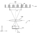
- FIG. 1A is a diagram showing a schematic configuration of an embodiment of an image display device according to the present invention.
- FIG. 1B is a diagram illustrating an example of a well shape.
- FIG. 2A is a diagram illustrating a more detailed configuration of the imaging unit.
- FIG. 2B is a diagram illustrating an aspect of scanning by the imaging unit.
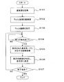
- FIG. 3 is a flowchart showing display processing in the image display apparatus.
- FIG. 4A is a first diagram illustrating the principle of reconstruction of a well image.
- FIG. 4B is a second diagram illustrating the principle of well image reconstruction.
- FIG. 5A is a first diagram illustrating a display example of a plate view.
- FIG. 5B is a second diagram illustrating a display example of a plate view.
- FIG. 5A is a first diagram illustrating a display example of a plate view.
- FIG. 6A is a first diagram illustrating a display example of an enlarged plate view.
- FIG. 6B is a second diagram illustrating a display example of the enlarged plate view.
- FIG. 7A is a first diagram illustrating the principle of creating a contour line.
- FIG. 7B is a second diagram illustrating the principle of creating a contour line.
- FIG. 7C is a third diagram illustrating the principle of creating a contour line.
- FIG. 8 is a diagram illustrating a display example of a single view.
- FIG. 9A is a first diagram illustrating a display example of an enlarged single view.
- FIG. 9B is a second diagram illustrating a display example of an enlarged single view.
- FIG. 10A is a first diagram illustrating another display example of the single view.
- FIG. 10B is a second diagram illustrating another display example of the single view.
- the image display device 1 includes a plurality of, for example, 96 pieces (12 ⁇ 8 matrix array) into which liquids such as a culture solution, a medium, and a reagent (only a part of which is shown) are injected.
- liquids such as a culture solution, a medium, and a reagent (only a part of which is shown) are injected.
- the sample 11 (microplate) M in which the well W is formed is in contact with the lower peripheral edge of the sample (microplate) M to hold the microplate M in a substantially horizontal state
- a light source 12 provided on the holder 11
- An imaging unit 13 provided at the lower portion of the holder 11 and a control unit 10 that controls these to execute a predetermined operation are provided.
- coordinate axes are set as shown in FIG. 1A.
- the XY plane is a horizontal plane
- the Z axis is a vertical axis.
- each well W in the microplate M is typically about several mm.
- the dimensions of each part of the microplate M used in the experiment by the present inventors are shown.
- the diameter Dt of the opening Wt at the top of each well W is 6.69 mm
- the inner diameter Db of the well bottom surface Wb is 6.58 mm.
- the inner wall surface Ws of the well W is not a simple cylindrical surface, but has a tapered shape with the side surfaces inclined obliquely.
- the depth Dd of the wells W is 10.9 mm
- the arrangement pitch Dp of the plurality of wells W is 9 mm.
- the dimension of each part is a mere example, Comprising: The size of the microplate which this image display apparatus 1 makes object is not limited to these, It is arbitrary.
- the light source 12 is controlled by a light source control unit 112 provided in the control unit 10 and is collectively applied to a plurality of wells W from above the microplate M held by the holder 11 in accordance with a control command from the light source control unit 112. Then, the light L is irradiated.
- the irradiated light is visible light, and white light is particularly preferable.
- the imaging unit 13 functions as a camera that captures an image of the microplate M by receiving transmitted light Lt emitted from the light source 12 and transmitted below the microplate M held by the holder 11. .
- the imaging unit 13 is connected to a camera driving mechanism 113 provided in the control unit 10, and the camera driving mechanism 113 moves the imaging unit 13 along the horizontal plane (XY) along the lower surface of the microplate M held by the holder 11. Scanning movement within a plane).
- the imaging unit 13 can be scanned and moved along the lower surface of the microplate M.
- the imaging unit 13 moves relative to the microplate M.
- Image data captured by the imaging unit 13 is given to the image processing unit 114.
- the image processing unit 114 appropriately performs image processing on the image data from the imaging unit 13 or executes predetermined calculation processing based on the image data. Data before and after processing is stored and saved in the storage unit 115 as necessary.
- the detection processing unit 116 performs a predetermined detection process based on the image data given from the image processing unit 114, and detects a characteristic part included in the image.
- This detection process is a process of detecting an area in which the optical characteristics are different from the surrounding area in the image, for example, by analyzing the luminance data of the image. Further, by calculating the feature amount for the area, it is possible to classify what kind of origin and type the area is of. Since various techniques are known for the process of identifying and detecting a part having a certain feature from the image and the feature amount suitable for such a process, detailed description thereof is omitted here.
- the detection result by the detection processing unit 116 is also stored in the storage unit 115.
- the image processing unit 114 may perform image processing based on the detection result of the detection processing unit 116 as necessary.
- the image data subjected to appropriate image processing is given to a display unit 118 having display means such as a liquid crystal display, and the display unit 118 displays an image corresponding to the given image data and presents it to the user.
- the image display device 1 includes an input receiving unit 117 for receiving an operation instruction input from the user regarding the contents of the image processing, the display mode, and the like.
- the input receiving unit 117 is an input receiving unit such as a keyboard, a mouse, and a touch pad, or a combination of them.
- the input receiving unit 117 receives an instruction input from the user, and the control unit 10 reflects this in the operation of the apparatus. The function desired by the user is realized.
- the image display device 1 captures an optical image of an imaging target such as a liquid held in each well W and cells contained therein, or has a predetermined optical characteristic from the optical image.
- the present invention can be applied to the use of detecting a specific portion having an optical characteristic different from that of the liquid or the like held in the well W by utilizing the difference in the optical characteristic.
- it can be suitably used for the purpose of imaging a cell or a cell clump (spheroid) in a culture solution or a medium as an imaging object, or automatically detecting such a cell or the like by image processing.
- “liquid or the like” is a general term for liquid, gel-like or semi-fluid solid, and those that are injected into a well in a fluid state such as soft agar and then solidified.
- FIG. 2A and 2B are diagrams showing a more detailed configuration of the imaging unit.
- the imaging unit 13 outputs, for example, a CCD line sensor 131 that outputs an electrical signal corresponding to incident light, and light emitted from the bottom surface of the microplate M held by the holder 11.
- an imaging optical system 132 that forms an image on the light receiving surface.
- the imaging optical system 132 may include a plurality of optical components such as lenses, but here, for easy understanding, a single lens is representatively shown here.
- the line sensor 131 is a one-dimensional array of a large number of fine imaging elements 131a in the Y direction.
- at least one whole well W In the longitudinal direction, at least one whole well W, more preferably a plurality of (see FIG. The three wells W are configured to be included in the imaging range SR at a time.
- the length of the line sensor 131 in the Y direction is indicated by a symbol w
- the length of the visual field on the bottom surface of the microplate M is indicated by a symbol w ′.
- the scanning movement direction of the line sensor 131 by the camera driving mechanism 113 is the X direction.
- the line sensor 131 in which the image pickup devices are arranged along the Y direction is scanned and moved in the X direction along the bottom surface of the microplate M, thereby capturing a two-dimensional image of the microplate M viewed from the bottom surface side. Is possible.
- a large number of wells W formed on the microplate M can be sequentially imaged.
- the line sensor 131 can obtain a high-definition image because the pixel size of each image sensor is small.
- an imaging optical system 132 is configured so that a large number of imaging elements are arranged in a line and an optical image of each part of the well W is formed on each imaging element, and these are arranged at appropriate positions. More light from the well W is incident on the line sensor 131. By doing so, the time required to image one well W is shortened. Thereby, imaging about many wells W can be performed at high speed. If an image of the entire microplate M is acquired in this way in advance, then the captured image is subjected to predetermined processing and displayed in various display modes described below, so that it can be displayed to the user. Various images will be presented in a manner according to the purpose.
- the imaging unit 13 images each well W of the microplate M in response to an operation instruction from the user via the input reception unit 117, and based on the image data.
- the image processing unit 114 and the detection processing unit 116 perform image processing and detection processing designated by the user, and the results are displayed on the display unit 118.
- the control unit 10 performs the series of processes described below, thereby realizing the above function.
- FIG. 3 is a flowchart showing display processing in this image display apparatus.
- the imaging unit 13 operates to capture the entire microplate M and acquire original images for all wells W (step S101).
- An image obtained by scanning the entire microplate M includes images of all wells W as partial images. Among these, the part which imaged the microplate M surface other than the well W is unnecessary, and it is useless from the point of utilizing the display space of the display part 118 effectively. Therefore, only the image of the portion corresponding to the well W is extracted from the obtained image and rearranged to reconstruct the image (step S102).
- FIG. 4A and 4B are diagrams showing the principle of reconstruction of a well image.
- the image Im showing the entire microplate M is composed of a plurality of band images Ib imaged by the imaging unit 13 scanning and moving with respect to the microplate M. Only partial images Ip corresponding to the respective wells W arranged in a matrix are cut out from the whole image Im, and as shown in FIG. 4B, well images Iw reconstructed by arranging the cut out partial images Ip are obtained. Since the diameter and arrangement pitch of each well W in the microplate M are known in advance, for example, it is possible to specify the region corresponding to each well W based on the coordinate position in the entire image Im. Alternatively, since the region corresponding to each well W is a substantially circular shape having a known size, the region corresponding to such a well W can also be specified by extracting a region corresponding to such a condition by image analysis. .
- the partial image Ip only a substantially circular area corresponding to each well W may be cut out, or as shown in FIG. 4A, the partial image Ip may be cut out by a rectangle including a circular area corresponding to the well W. It may be an image. In the latter case, a desired partial image Ip is obtained by cutting out a square region whose center is located at the center of gravity of the well W and whose length of one side is substantially equal to the diameter of the well W, that is, circumscribing the circular region of the well W. It is done.
- the positional relationship between the wells W in the reconstructed well image Iw is arranged to be the same as the positional relationship between the wells in the entire image Im, that is, the positional relationship between the wells W on the actual microplate M. . That is, in the whole image Im shown in FIG. 4A, wells Wa1, Wa2, Wa3,... Are arranged in order from the upper left corner to the right, and wells Wa1, Wb1, Wc1,. Are in order. As shown in FIG. 4B, also in the reconstructed well image Iw, partial images Ipa1, Ipa2, Ipa3,... Corresponding to wells Wa1, Wa2, Wa3,... Are arranged in order from the upper left corner to the right. .. And partial images Ipa1, Ipb1, Ipc1,... Corresponding to wells Wa1, Wb1, Wc1,... Are arranged in order from the upper left corner downward.
- Each of the partial images Ipa1, Ipa2, Ipa3,... Cut out from the entire image Im is treated as a well-unit original image corresponding to each of the wells Wa1, Wa2, Wa3,.
- the arrangement positions on the microplate M are associated as index information. Specifically, a row index of 1 to 12 is assigned to each well arranged in the horizontal direction (row direction) in FIG. 4B.
- column indexes A to H are assigned to the wells arranged in the vertical direction (column direction).
- each well can be identified by a combination of alphabets A to H and numbers 1 to 12.
- step S103 The whole well image Iw created in this way is displayed on the display unit 118 (step S103). Thereby, the user can confirm the outline of the captured image. In this state, the system waits until an instruction input regarding the display mode is given from the user (step S104).
- Various display modes that are effective for supporting the user's observation of the well W can be adopted, but a part thereof is illustrated here.
- the first element related to the display mode is whether to display the whole of the plurality of wells W arranged on the microplate M or to display each well W individually.
- One of the purposes of using this type of apparatus is, for example, to display images of a plurality of samples created by changing conditions for each well W on the same screen, and comparatively observe them.
- a display mode for simultaneously displaying images corresponding to a plurality of wells W is necessary.
- the arrangement of the wells W in the displayed image matches the actual arrangement on the microplate M, the user can easily grasp the relationship between the wells W.
- the captured whole image Im of the microplate M is displayed as it is, blank portions other than the wells on the microplate M reduce the use efficiency of the display area.
- a partial image Ip corresponding to each well W is cut out from the entire image Im of the microplate M, and a well image Iw formed by arranging them in the same arrangement as the arrangement on the microplate M can be displayed. To do.
- a display mode is referred to as “plate view” in this specification. In the plate view, it is not always necessary to display all the wells W. If necessary, only some of the wells W may be displayed while maintaining the arrangement.
- each well W there is a purpose of observing the image of each well W in more detail, and a function for selecting an arbitrary well W by the user and displaying only the well is also required.
- Such a display mode is referred to as “single view” in this specification.
- the second factor related to the display mode is the magnification of the image.
- magnification of the image For the user, there are both a case where the user wants to look down on the entire image and a case where he wants to enlarge a part of the image. Therefore, it is preferable to have a function of displaying an image enlarged or reduced to an arbitrary magnification.
- the third element related to the display mode relates to the mode of image processing for the displayed image. It is possible not only to display the captured original image as it is, but also to support the user's observation work more effectively by analyzing the image and adding and displaying various information based on the result. Become.
- Various image analysis techniques are known, and various analysis techniques can also be applied to this embodiment.
- a classification technique for classifying various objects included in an image according to their optical or geometric characteristics.
- the classification can be performed based on the feature amount of the object calculated.
- the criteria for classification the size, density, area, circumscribed circle diameter, circumscribed sphere volume, cell type estimated from them, etc. can be used alone or in appropriate combination.
- step S104 when one display mode is specified by an instruction input from the user from among a plurality of display modes specified by the combination of the above three types of elements (step S104), the specification is made.
- Image processing necessary for performing display in the displayed display mode is performed (step S105). More specifically, the image processing unit 114 and the detection processing unit 116 perform various kinds of analysis / classification processing on the image and image processing for processing the image based on the result thereof, and the partial image Ip corresponding to each well W. Is performed on a display target.
- each processed partial image is used as a material image, and the image processing unit 114 creates a display image arranged in the display area with a predetermined arrangement and magnification, and the display unit 118 displays the display image.
- Step S106 a new instruction input from the user is awaited (step S107), and if there is an end instruction, the process is terminated, while if there is a new mode instruction input, a process corresponding thereto is executed again.
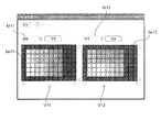
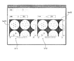
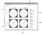
- 5A and 5B are diagrams showing display examples of the plate view.
- the work of preparing a sample in which the drug concentration in each well is regularly changed along the array and observing the sample is frequently used.
- the visibility of the array of each well is important.
- FIG. 5A shows an example of a plate view image corresponding to a microplate having 96 holes (12 holes ⁇ 8 rows).
- Each well is displayed not in the original image as it is, but in a color-coded state (gray scale display in the figure) based on the result classified based on the designated standard.
- the well images Iw11 and Iw12 displayed in the two display areas V11 and V12 correspond to the same image obtained by imaging the same microplate, but display contents are different because designated classification criteria are different from each other. Are generally different from each other.
- the well image Iw11 displayed in the left display area V11 has the area of the object included in each well as a reference parameter, as shown in the menu area M11 arranged above the display area V11. It is color-coded according to the classification result. That is, the area of each object included in each well is obtained by the image processing unit 114 and the detection processing unit 116, and each well is filled with a color corresponding to the average value of the areas obtained for each well. It is.
- the well image Iw12 displayed in the right display area V12 as shown in the upper menu area M12, it is based on the classification based on the diameter of the object (more specifically, the diameter of the circumscribed circle of the object) included in each well. Color coding is done.
- the user can be presented with an image in which the general tendency of the change in the shape of the object (cell agglomeration) that occurs between the wells as the drug concentration changes can be easily recognized. it can.
- an environment in which the user can perform observation work more efficiently can be provided.
- each well is filled with a color corresponding to the average value in the well of the parameter designated as the classification standard.
- the background of each well may be colored according to the value of the reference parameter.
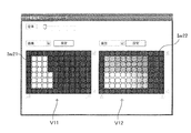
- the user can switch display images in various ways by operating various setting functions displayed on the screen as necessary. That is, the user can click the menu area M11 on the screen or the “Setting” button to call up various setting menus and make settings. Further, the display magnification of the image can be increased / decreased by the “magnification” button.
- a new display mode is designated in this way, the processing from step S105 onward in FIG. 3 is re-executed, and an image in the designated display mode is displayed.
- the well image Iw21 displayed in the left display region V11 is an image binarized with a predetermined threshold with respect to the area of the object. Whether to display a multi-valued image or a binarized image, how to set a threshold value for binarization, and the like can be set by a setting menu.
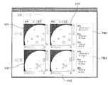
- FIG. 6A and 6B are diagrams showing display examples of the enlarged plate view.
- the example shown in FIG. 6A assumes a medium magnification (for example, 5 times), but the user can arbitrarily set the magnification by operating the operation bar (magnification bar) displayed at the top of the image. it can. At this time, the same magnification is applied to both of the enlarged well images Iw31 and Iw32 displayed in the two display areas V11 and V12. Even in the enlarged image, the positional relationship between the wells is maintained.
- a partial range of the well image is enlarged and displayed in the display areas V11 and V12, and outside the display area.
- An operation bar (scroll bar) is displayed so that the display range in the well image can be moved.
- the enlarged well images Iw31 and Iw32 always indicate the same range in the original well image. That is, when the scroll bar is operated in one of the images, the display ranges of the two enlarged well images Iw31 and Iw32 change at the same time.
- each well is displayed in a relatively large area
- the well is not filled in units of wells, and color coding and hatching based on the classification criteria are applied to each object included in each well. Processing such as is given.
- the user can create an environment for comparing wells that are close to each other (that is, the creation conditions are slightly different) while closely observing the distribution of objects in each well. Can be provided. By making it possible to continuously change the display range and magnification using the operation bar, comparative observation between wells can be easily performed.
- a pair of wells to be compared are displayed in the same positional relationship by linking the two images Iw31 and Iw32 so that the magnifications of the two images Iw32 and the display range of the whole well image match. Therefore, the user can observe each well while always comparing the analysis results based on different criteria.
- the example shown in FIG. 6B is a display example of the plate view when the enlargement magnification is set to the maximum.
- the enlargement magnification is selected so that approximately one well can be accommodated in each of the display areas V11 and V12.
- each object in the well is displayed while maintaining the color of the original image, and only its outline is colored based on the classification criteria (in the figure, the difference in the dot pitch of the broken line indicates the outline. Shows the difference in color).
- the outline of the object can be created as follows, for example.
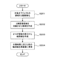
- FIG. 7A to FIG. 7C are diagrams showing the principle of outline creation.
- FIG. 7A is a flowchart showing a contour line creation process.
- the area of the object in the image is extracted as a binary image (step S201).
- the area of the object is filled with a predetermined pixel value.
- the region extracted as the binary image is contracted by a predetermined number of pixels by, for example, erosion processing in morphology processing (step S202).
- the number of pixels to be contracted is preferably selected to be a sufficiently small value with respect to the size of the region so that the shape of the region itself does not change greatly, and can be set to, for example, one pixel.
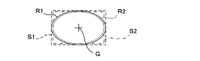
- the contracted region R2 is subtracted from the original binary image region R1 (step S203).
- the pixel value is canceled at the portion where the two regions R1 and R2 overlap, while at the peripheral portion, the outer peripheral portion (the hatched portion in FIG. 7B) of the original image region R1 by the number of contracted pixels. ) Will remain.
- the remaining part is combined with the original image and superimposed on the object as an outline of the object (step S204), so that the outline of the object can be highlighted.
- the object region in the original image, the binarized image region, and the posture and position of the image region obtained by contracting the region are aligned with each other. This is very important.
- rectangles S1 and S2 circumscribing these image regions R1 and R2 are virtually set, and the centroids G of the rectangles S1 and S2 are equal to each other.
- the image regions may be overlapped so that the corresponding sides are parallel to each other.
- the function of the plate view for displaying a plurality of wells W in the same arrangement as that on the microplate M has been described.
- the user can observe each well with the same operability as when directly observing the microplate M.
- it can observe from various viewpoints by displaying the classification results based on different criteria side by side.
- two types of classification results for the portion to be observed are always presented by linking the image magnification and display range in the two display areas.
- observation can be performed more efficiently.
- the aspect of the visual information attached to the image is automatically changed according to the change in magnification, it is possible to easily visually recognize the state of each well or each object in the well in each magnification image. Is possible.
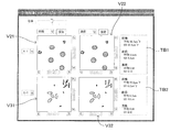
- step S104 of FIG. 3 when the user selects a single view as the display mode and selects a well to be displayed, a single view display screen exemplified below is displayed.
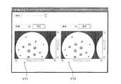
- FIG. 8 is a diagram showing a display example of a single view.
- the single view display screen four display areas V21, V22, V31, and V32 are arranged in a 2 ⁇ 2 matrix, and one partial image Ip corresponding to a single well is displayed in each display area.
- the upper two display areas V21 and V22 are images reflecting the results of classifying the same wells according to different criteria (in this example, the area and diameter of the object), specifically these reference parameters.
- An image in which the object is colored according to the value is displayed.
- the well displayed here is a well specified by the index information “A-1”, and the upper left corner in the plate image Ip shown in FIG. 4A. This corresponds to the well Wa1 located at.
- the user can change the well to be displayed by operating the pull-down menu.
- the area and diameter of the object are added to the original image corresponding to another well (in this example, the well Wc1 specified by the index “C-1”).
- Images reflecting the classification results based on the respective standards are displayed. That is, in this display mode, images representing the results of classifying the same wells with different criteria are displayed side by side in the left-right direction, while images representing the results of classifying different wells according to the same criteria are arranged in the vertical direction. Is displayed.
- text boxes TB1 and TB2 for displaying the analysis results in the corresponding wells by numerical values are provided at the right ends of the upper and lower stages.
- statistical information average value and standard deviation (SD) value
- SD standard deviation
- the user can observe an image while comparing the results of classifying two wells with two criteria, respectively. Further, the wells to be displayed and the classification criteria can be observed while appropriately switching them by operating the menu box. Further, more detailed information about each well can be obtained from the text information displayed in the text box. Thus, in this embodiment, detailed observation of wells, in particular, comparative observation between different wells or between different classification criteria of the same well can be efficiently performed.
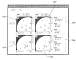
- FIG. 9A and FIG. 9B are diagrams showing a display example of an enlarged single view.
- FIG. 9A shows a display example when a medium (for example, 5 times) enlargement magnification is selected
- FIG. 9B shows a display example when the maximum magnification is selected.
- the display magnification of the image can be changed as appropriate in the single view, and the display range is linked in each display area when the whole well does not fit in the display range.
- the mode of the visual information given to the image to represent the classification result is automatically changed according to the change in display magnification.
- the user can simultaneously observe the results of image processing of the same well using different standards and between different wells using the same standard. Note that the statistical information displayed in the text boxes TB1 and TB2 represents the analysis result of one whole well, and does not change by changing the display magnification.
- FIG. 10A and 10B are diagrams showing other display examples of the single view.
- the number of detected objects that match the matching conditions specified by the user is displayed at the upper left of the area for each display area.
- this embodiment is an image display device for observing biological samples such as cells and cell clumps, for example, and allows a user to observe a plurality of images while comparing them.
- Various display functions are provided.
- the plate view function for displaying wells W on the microplate M generally, (1) Extracting images of well portions to be observed from an original image obtained by scanning the imaging unit with respect to the microplate, and displaying them in an arrangement according to the arrangement on the microplate. (2) About each well, the visual information (for example, color coding) according to the classification result based on the classification standard designated by the user is given and displayed. (3) The visual information can be changed by user designation. (4) Two kinds of classification results based on different classification criteria are displayed side by side in two display areas on the screen.
- each object in the well is displayed with visual information based on the classification result.
- the visual information to be given to the well or the object is automatically changed according to the designated display magnification. The function is realized.
- this embodiment it is possible to provide the user with an environment in which the sample can be efficiently observed from various viewpoints.
- comparison between different wells and comparison of results obtained by analyzing the same well from different viewpoints are facilitated.
- observing the state at the level of cell clumps rather than observing individual cells or their internal structures is useful for, for example, cell drug susceptibility testing.
- the microplate M corresponds to the “sample holding plate” of the present invention
- each well W corresponds to the “concave portion” of the present invention
- the partial image Ip corresponding to each well in the original image Im of the entire plate corresponds to the “original image” of the present invention
- the image after performing image processing on the image is the “material image” of the present invention. Is equivalent to.
- Each of the images shown in FIGS. 5, 6, 8 to 10 including this material image corresponds to the “display image” of the present invention.
- the detection processing unit 116 functions as the “specific part detection unit” and the “feature amount calculation unit” of the present invention, while the image processing unit 114 functions as the “visual information adding unit” of the present invention. These function as a whole and function as the “image processing means” of the present invention.
- the input receiving unit 117 functions as the “receiving unit” of the present invention
- the display unit 118 functions as the “displaying unit” of the present invention
- the imaging unit 13 functions as the “imaging unit” of the present invention.
- steps S104, S105, and S106 correspond to the “accepting process”, “image creating process”, and “display process” of the present invention, respectively.
- the present invention is not limited to the above-described embodiment, and various modifications other than those described above can be made without departing from the spirit of the present invention.
- the above-described embodiment is an image display device including an imaging unit that images a well formed on a microplate.
- the display processing of the present embodiment assists the user's observation by variously processing and displaying an image obtained by imaging the entire microplate. Therefore, even if the display mode is changed, imaging is performed again. Is not required. In this sense, it is not essential to include an imaging unit.
- the present invention also applies to an apparatus that receives image data captured by another imaging apparatus via an appropriate communication unit, processes the image data, and displays the processed image data. It is possible to apply.
- the objects in the well are classified based on criteria mainly related to the shape such as the area and diameter, but the classification criteria are not limited to these, and are used for observation of cells and biological tissues.
- Various classification criteria that can be applied are applicable. For example, an application is conceivable in which the cell type is comprehensively determined from the shape, color, size, etc. of the object, and the color is displayed for each cell type. Further, classification based on case learning using known samples may be applied.
- imaging is performed by relatively moving the line sensor 131 formed by one-dimensionally arranging the imaging elements with respect to the microplate M, but a CCD array in which the imaging elements are arranged in a two-dimensional matrix is used. May be used to perform imaging.
- the present invention can be particularly preferably applied to a field that requires observation of a sample held in each of a large number of wells, such as a microplate used in the medical / biological science field. Is not limited to the medical and biological science fields.
- Imaging unit imaging means
- Image processing unit visual information adding unit, image processing means
- Detection processing unit specific part detection unit, feature amount calculation unit, image processing means
- Input reception part reception means
- Display display means
- Ip partial image original image
- M microplate sample holding plate
- S104 Reception process S105 Image creation process
- S106 Display process W well (recessed part)
Landscapes
- Engineering & Computer Science (AREA)
- Physics & Mathematics (AREA)
- General Physics & Mathematics (AREA)
- Theoretical Computer Science (AREA)
- General Health & Medical Sciences (AREA)
- Health & Medical Sciences (AREA)
- Medical Informatics (AREA)
- Computer Vision & Pattern Recognition (AREA)
- Quality & Reliability (AREA)
- Radiology & Medical Imaging (AREA)
- Nuclear Medicine, Radiotherapy & Molecular Imaging (AREA)
- Computer Hardware Design (AREA)
- Multimedia (AREA)
- Molecular Biology (AREA)
- Biomedical Technology (AREA)
- Life Sciences & Earth Sciences (AREA)
- Investigating Or Analysing Materials By Optical Means (AREA)
- Image Processing (AREA)
- Microscoopes, Condenser (AREA)
- Image Analysis (AREA)
Priority Applications (1)
| Application Number | Priority Date | Filing Date | Title |
|---|---|---|---|
| US14/366,544 US20140320513A1 (en) | 2011-12-28 | 2012-05-29 | Image display apparatus and image display method |
Applications Claiming Priority (2)
| Application Number | Priority Date | Filing Date | Title |
|---|---|---|---|
| JP2011287966A JP2013137635A (ja) | 2011-12-28 | 2011-12-28 | 画像表示装置および画像表示方法 |
| JP2011-287966 | 2011-12-28 |
Publications (1)
| Publication Number | Publication Date |
|---|---|
| WO2013099045A1 true WO2013099045A1 (ja) | 2013-07-04 |
Family
ID=48696603
Family Applications (1)
| Application Number | Title | Priority Date | Filing Date |
|---|---|---|---|
| PCT/JP2012/003487 Ceased WO2013099045A1 (ja) | 2011-12-28 | 2012-05-29 | 画像表示装置および画像表示方法 |
Country Status (3)
| Country | Link |
|---|---|
| US (1) | US20140320513A1 (enExample) |
| JP (1) | JP2013137635A (enExample) |
| WO (1) | WO2013099045A1 (enExample) |
Cited By (4)
| Publication number | Priority date | Publication date | Assignee | Title |
|---|---|---|---|---|
| CN110447238A (zh) * | 2017-01-27 | 2019-11-12 | 舒尔获得控股公司 | 阵列麦克风模块及系统 |
| WO2019225176A1 (ja) * | 2018-05-25 | 2019-11-28 | ソニー株式会社 | 制御装置、制御方法、およびプログラム |
| JP2020525793A (ja) * | 2017-06-27 | 2020-08-27 | ライフ テクノロジーズ ホールディング プライベート リミテッド | 液体試料を分析する方法、マイクロプレートリーダー、およびコンピュータプログラム |
| JP2022170904A (ja) * | 2021-04-30 | 2022-11-11 | 株式会社キーエンス | 分析装置 |
Families Citing this family (10)
| Publication number | Priority date | Publication date | Assignee | Title |
|---|---|---|---|---|
| WO2016158719A1 (ja) * | 2015-03-31 | 2016-10-06 | 株式会社Screenホールディングス | 画像処理方法、制御プログラムおよび画像処理装置 |
| JPWO2017150194A1 (ja) * | 2016-03-04 | 2018-12-27 | コニカミノルタ株式会社 | 画像処理装置、画像処理方法及びプログラム |
| US10528792B2 (en) | 2016-06-17 | 2020-01-07 | Canon Kabushiki Kaisha | Display apparatus and display control method for simultaneously displaying a plurality of images |
| WO2018061131A1 (ja) * | 2016-09-28 | 2018-04-05 | オリンパス株式会社 | 細胞状態計測装置 |
| JP7365241B2 (ja) * | 2017-06-27 | 2023-10-19 | ライフ テクノロジーズ ホールディングス プライベート リミテッド | サンプルの分析方法、分析装置、およびコンピュータプログラム |
| WO2019106945A1 (ja) * | 2017-11-28 | 2019-06-06 | パナソニックIpマネジメント株式会社 | 培養状態判定装置、培養状態判定方法及びプログラム |
| US11474007B2 (en) | 2019-01-04 | 2022-10-18 | Funai Electric Co., Ltd. | Digital dispense system |
| US20200217764A1 (en) * | 2019-01-04 | 2020-07-09 | Funai Electric Co., Ltd. | Digital dispense system |
| WO2021059487A1 (ja) * | 2019-09-27 | 2021-04-01 | 株式会社ニコン | 情報処理装置、情報処理方法、情報処理プログラム、及び情報処理システム |
| JP2023128033A (ja) * | 2022-03-02 | 2023-09-14 | 株式会社Screenホールディングス | 疾患評価支援方法および疾患評価支援装置 |
Citations (5)
| Publication number | Priority date | Publication date | Assignee | Title |
|---|---|---|---|---|
| JPH09145594A (ja) * | 1995-11-20 | 1997-06-06 | Medica Tec Kk | 臨床検査における反応済検体の粒子凝集パターンの判定方法及び粒子凝集パターンの表示とプリント方式 |
| JP2002355090A (ja) * | 1997-02-27 | 2002-12-10 | Cellomics Inc | 細胞に基づくスクリーニングシステム |
| JP2003500664A (ja) * | 1999-05-24 | 2003-01-07 | セロミックス インコーポレイテッド | 実験データの汎用解析のための方法およびシステム |
| JP2009512927A (ja) * | 2005-10-20 | 2009-03-26 | ジーイー・ヘルスケア・ユーケイ・リミテッド | 画像処理方法 |
| WO2011004568A1 (ja) * | 2009-07-08 | 2011-01-13 | 株式会社ニコン | 受精卵観察の画像処理方法、画像処理プログラム及び画像処理装置、並びに受精卵の製造方法 |
Family Cites Families (7)
| Publication number | Priority date | Publication date | Assignee | Title |
|---|---|---|---|---|
| US5989835A (en) * | 1997-02-27 | 1999-11-23 | Cellomics, Inc. | System for cell-based screening |
| TWI274289B (en) * | 2001-02-19 | 2007-02-21 | Olympus Corp | Image comparing device, image comparing method and program for executing image comparison in computer recording medium |
| JP4155496B2 (ja) * | 2002-04-25 | 2008-09-24 | 大日本スクリーン製造株式会社 | 分類支援装置、分類装置およびプログラム |
| EP1609850A1 (en) * | 2004-06-24 | 2005-12-28 | Biovir v/Jacob Mollenbach | Culture dish for culturing biological cells |
| US20080226126A1 (en) * | 2005-01-31 | 2008-09-18 | Yoshinori Ohno | Object-Tracking Apparatus, Microscope System, and Object-Tracking Program |
| JP4690119B2 (ja) * | 2005-06-16 | 2011-06-01 | オリンパス株式会社 | 画像処理装置および画像処理プログラム |
| EP2202291B1 (en) * | 2007-09-03 | 2019-02-27 | Nikon Corporation | Culture apparatus, culture information management method, and program |
-
2011
- 2011-12-28 JP JP2011287966A patent/JP2013137635A/ja active Pending
-
2012
- 2012-05-29 WO PCT/JP2012/003487 patent/WO2013099045A1/ja not_active Ceased
- 2012-05-29 US US14/366,544 patent/US20140320513A1/en not_active Abandoned
Patent Citations (5)
| Publication number | Priority date | Publication date | Assignee | Title |
|---|---|---|---|---|
| JPH09145594A (ja) * | 1995-11-20 | 1997-06-06 | Medica Tec Kk | 臨床検査における反応済検体の粒子凝集パターンの判定方法及び粒子凝集パターンの表示とプリント方式 |
| JP2002355090A (ja) * | 1997-02-27 | 2002-12-10 | Cellomics Inc | 細胞に基づくスクリーニングシステム |
| JP2003500664A (ja) * | 1999-05-24 | 2003-01-07 | セロミックス インコーポレイテッド | 実験データの汎用解析のための方法およびシステム |
| JP2009512927A (ja) * | 2005-10-20 | 2009-03-26 | ジーイー・ヘルスケア・ユーケイ・リミテッド | 画像処理方法 |
| WO2011004568A1 (ja) * | 2009-07-08 | 2011-01-13 | 株式会社ニコン | 受精卵観察の画像処理方法、画像処理プログラム及び画像処理装置、並びに受精卵の製造方法 |
Cited By (11)
| Publication number | Priority date | Publication date | Assignee | Title |
|---|---|---|---|---|
| CN110447238A (zh) * | 2017-01-27 | 2019-11-12 | 舒尔获得控股公司 | 阵列麦克风模块及系统 |
| US11647328B2 (en) | 2017-01-27 | 2023-05-09 | Shure Acquisition Holdings, Inc. | Array microphone module and system |
| US12063473B2 (en) | 2017-01-27 | 2024-08-13 | Shure Acquisition Holdings, Inc. | Array microphone module and system |
| JP2020525793A (ja) * | 2017-06-27 | 2020-08-27 | ライフ テクノロジーズ ホールディング プライベート リミテッド | 液体試料を分析する方法、マイクロプレートリーダー、およびコンピュータプログラム |
| JP7531277B2 (ja) | 2017-06-27 | 2024-08-09 | ライフ テクノロジーズ ホールディングス プライベート リミテッド | 液体試料を分析する方法、マイクロプレートリーダー、およびコンピュータプログラム |
| WO2019225176A1 (ja) * | 2018-05-25 | 2019-11-28 | ソニー株式会社 | 制御装置、制御方法、およびプログラム |
| JPWO2019225176A1 (ja) * | 2018-05-25 | 2021-07-08 | ソニーグループ株式会社 | 制御装置、制御方法、およびプログラム |
| US11521320B2 (en) | 2018-05-25 | 2022-12-06 | Sony Corporation | Control device, control method, and program |
| JP7420069B2 (ja) | 2018-05-25 | 2024-01-23 | ソニーグループ株式会社 | 制御装置、制御方法、およびプログラム |
| JP2022170904A (ja) * | 2021-04-30 | 2022-11-11 | 株式会社キーエンス | 分析装置 |
| JP7724076B2 (ja) | 2021-04-30 | 2025-08-15 | 株式会社キーエンス | 分析装置 |
Also Published As
| Publication number | Publication date |
|---|---|
| US20140320513A1 (en) | 2014-10-30 |
| JP2013137635A (ja) | 2013-07-11 |
Similar Documents
| Publication | Publication Date | Title |
|---|---|---|
| WO2013099045A1 (ja) | 画像表示装置および画像表示方法 | |
| JP6333145B2 (ja) | 画像処理方法および画像処理装置 | |
| US8000511B2 (en) | System for and method of focusing in automated microscope systems | |
| EP3926583B1 (en) | Image processing method, computer program and recording medium | |
| EP3121287B1 (en) | Drug efficacy evaluation method and image processing device for drug efficacy evaluation | |
| US20100040266A1 (en) | System for and method of intelligently directed segmentation analysis for automated microscope systems | |
| US9645381B2 (en) | Multi-surface optical 3D microscope | |
| EP3124953A1 (en) | Spheroid evaluation method and spheroid evaluation device | |
| US10921252B2 (en) | Image processing apparatus and method of operating image processing apparatus | |
| US9214019B2 (en) | Method and system to digitize pathology specimens in a stepwise fashion for review | |
| WO2017150194A1 (ja) | 画像処理装置、画像処理方法及びプログラム | |
| US11010914B2 (en) | Image processing device, microscope system, image processing method, and program | |
| JP2016014974A (ja) | 画像処理方法および画像処理装置 | |
| US20230386233A1 (en) | Method for classifying a sequence of input images representing a particle in a sample over time | |
| JP7626765B2 (ja) | 試料観察装置及び試料観察方法 | |
| US10690902B2 (en) | Image processing device and microscope system | |
| JP6470399B2 (ja) | 画像処理方法、制御プログラムおよび画像処理装置 | |
| JP5762315B2 (ja) | 画像処理方法 | |
| JP2010117229A (ja) | 高さ情報取得装置、高さ情報取得方法、及びプログラム | |
| JP6276220B2 (ja) | 撮像装置および撮像方法 | |
| WO2023008180A1 (ja) | 画像処理方法、コンピュータープログラムおよび記録媒体 | |
| JP5869920B2 (ja) | 画像評価方法 | |
| KR20240035886A (ko) | 컴퓨터 시스템 및 해석 방법 | |
| EP4125065B1 (en) | Image processing method and classification model construction method | |
| Al-Kofahi et al. | Rapid Automated 3-D Tracing of Neurons from Confocal Image Stacks |
Legal Events
| Date | Code | Title | Description |
|---|---|---|---|
| 121 | Ep: the epo has been informed by wipo that ep was designated in this application |
Ref document number: 12862577 Country of ref document: EP Kind code of ref document: A1 |
|
| WWE | Wipo information: entry into national phase |
Ref document number: 14366544 Country of ref document: US |
|
| NENP | Non-entry into the national phase |
Ref country code: DE |
|
| 122 | Ep: pct application non-entry in european phase |
Ref document number: 12862577 Country of ref document: EP Kind code of ref document: A1 |