WO2013099045A1 - Image display device and image display method - Google Patents
Image display device and image display method Download PDFInfo
- Publication number
- WO2013099045A1 WO2013099045A1 PCT/JP2012/003487 JP2012003487W WO2013099045A1 WO 2013099045 A1 WO2013099045 A1 WO 2013099045A1 JP 2012003487 W JP2012003487 W JP 2012003487W WO 2013099045 A1 WO2013099045 A1 WO 2013099045A1
- Authority
- WO
- WIPO (PCT)
- Prior art keywords
- image
- display
- well
- images
- image processing
- Prior art date
Links
Images


Classifications
-
- G—PHYSICS
- G06—COMPUTING; CALCULATING OR COUNTING
- G06T—IMAGE DATA PROCESSING OR GENERATION, IN GENERAL
- G06T7/00—Image analysis
- G06T7/0002—Inspection of images, e.g. flaw detection
- G06T7/0012—Biomedical image inspection
-
- G—PHYSICS
- G06—COMPUTING; CALCULATING OR COUNTING
- G06V—IMAGE OR VIDEO RECOGNITION OR UNDERSTANDING
- G06V20/00—Scenes; Scene-specific elements
- G06V20/60—Type of objects
- G06V20/69—Microscopic objects, e.g. biological cells or cellular parts
- G06V20/695—Preprocessing, e.g. image segmentation
-
- G—PHYSICS
- G09—EDUCATION; CRYPTOGRAPHY; DISPLAY; ADVERTISING; SEALS
- G09G—ARRANGEMENTS OR CIRCUITS FOR CONTROL OF INDICATING DEVICES USING STATIC MEANS TO PRESENT VARIABLE INFORMATION
- G09G5/00—Control arrangements or circuits for visual indicators common to cathode-ray tube indicators and other visual indicators
- G09G5/22—Control arrangements or circuits for visual indicators common to cathode-ray tube indicators and other visual indicators characterised by the display of characters or indicia using display control signals derived from coded signals representing the characters or indicia, e.g. with a character-code memory
- G09G5/30—Control of display attribute
-
- G—PHYSICS
- G02—OPTICS
- G02B—OPTICAL ELEMENTS, SYSTEMS OR APPARATUS
- G02B21/00—Microscopes
- G02B21/34—Microscope slides, e.g. mounting specimens on microscope slides
-
- G—PHYSICS
- G06—COMPUTING; CALCULATING OR COUNTING
- G06T—IMAGE DATA PROCESSING OR GENERATION, IN GENERAL
- G06T2200/00—Indexing scheme for image data processing or generation, in general
- G06T2200/24—Indexing scheme for image data processing or generation, in general involving graphical user interfaces [GUIs]
-
- G—PHYSICS
- G06—COMPUTING; CALCULATING OR COUNTING
- G06T—IMAGE DATA PROCESSING OR GENERATION, IN GENERAL
- G06T2207/00—Indexing scheme for image analysis or image enhancement
- G06T2207/10—Image acquisition modality
- G06T2207/10056—Microscopic image
-
- G—PHYSICS
- G06—COMPUTING; CALCULATING OR COUNTING
- G06T—IMAGE DATA PROCESSING OR GENERATION, IN GENERAL
- G06T2207/00—Indexing scheme for image analysis or image enhancement
- G06T2207/30—Subject of image; Context of image processing
- G06T2207/30004—Biomedical image processing
- G06T2207/30024—Cell structures in vitro; Tissue sections in vitro
-
- G—PHYSICS
- G06—COMPUTING; CALCULATING OR COUNTING
- G06T—IMAGE DATA PROCESSING OR GENERATION, IN GENERAL
- G06T2207/00—Indexing scheme for image analysis or image enhancement
- G06T2207/30—Subject of image; Context of image processing
- G06T2207/30004—Biomedical image processing
- G06T2207/30072—Microarray; Biochip, DNA array; Well plate
Definitions
- the present invention relates to an image display device and an image display method for displaying an image reflecting a result of performing predetermined image processing on an image obtained by imaging a recess of a sample holding plate.
- a cell (culture medium) or culture medium is injected into each well of a plate-like instrument provided with a large number of depressions, also called wells, and cultured here Etc. are performed.
- a plate-like instrument provided with a large number of depressions, also called wells, and cultured here Etc.
- Such an instrument is called, for example, a microplate or a microtiter plate.
- a technique for example a method of fluorescently emitting a specific molecule by pretreatment of a sample or use of a reagent has been conventionally performed.
- a technique for analyzing and displaying an original image using an image processing technique has been studied. For example, in the image processing system described in Patent Document 1, a plurality of living cells are taken as observation samples, the image is captured, and an image colored according to the feature amount is displayed for a cell region recognized by analyzing the image. It is configured to let you.
- the present invention has been made in view of the above problems, and in the technology for displaying an image obtained by imaging the recess of the sample holding plate, an image display device or an image for displaying an image that can meet the user's request as described above It is intended to provide a display method.
- One aspect of the present invention is an image display device that displays an image obtained by imaging the recess of a sample holding plate in which a plurality of recesses for holding a sample are arranged.
- An image for display in which a raw material image obtained by performing image processing for giving visual information according to the content of the original image to the original image obtained by imaging the depression is provided, and a plurality of different raw material images are arranged Image processing means for generating the image and display means for displaying the display image.
- an image display method for displaying an image obtained by imaging the depression of a sample holding plate in which a plurality of depressions for holding a sample are arranged.
- the display image is (1) a set of a plurality of material images obtained by performing the same image processing on each of the original images corresponding to the different recesses, and (2) the same.
- the original image includes at least one of a plurality of sets of the material images obtained by performing different image processing on the original image.
- means for giving visual information to the material image for example, color coding, painting, changing brightness, emphasizing contours, adding a frame or pointer, adding text information, or a combination thereof It is possible to use.
- a display image corresponding to an instruction input from a user regarding at least one of selection of a material image and selection of contents of image processing may be created.
- the image processing unit includes a specific part detection unit that detects a specific part having specific optical characteristics in the original image, and a feature that calculates a feature amount of the detected specific part. You may make it provide the amount calculation part and the visual information provision part which provides the visual information according to the value of the calculated feature-value to an original image. In this way, it is possible to present to the user a display image that makes it possible to easily distinguish a part (specific part) having a specific feature included in the image from other parts.
- the visual information giving unit may give visual information corresponding to the value of the feature amount calculated for the specific part at a position corresponding to the specific part in the original image, for example.
- the user can easily grasp the distribution status of the specific part, and can easily compare the distribution status among a plurality of material images.
- the display image may be created so as to include a plurality of material images each provided with visual information based on different feature amounts with respect to the same original image. In this way, since the material images obtained by processing one sample from different viewpoints are displayed at the same time, the user can observe the sample more efficiently.
- a display image may be created in which a plurality of material images corresponding to different recesses are arranged in correspondence with the arrangement order of the recesses on the sample holding plate. In this way, the user can easily grasp the relationship between displayed material images, and can efficiently perform comparative observation.
- the display magnification of the material image in the display image can be changed and set, and the visual information added to the material image may be different according to the set display magnification. This makes it possible to present a display image that is easier for the user to visually recognize.
- a display image including a plurality of material images obtained by performing different image processing on the same partial region in the same original image may be created.
- the user may desire to display only a partial region of the original image. In such a case, if a plurality of material images corresponding to a partial area of the original image represent the same area, it is possible to support the user's observation more efficiently.
- a display image including a material image and character information related to the content of the material image may be created. In this way, more detailed information regarding the image content can be provided to the user.
- the present invention may include an image pickup unit that picks up an original image by scanning and moving the image pickup device relative to the sample holding plate.
- an image pickup unit that picks up an original image by scanning and moving the image pickup device relative to the sample holding plate.
- the image display apparatus configured as described above, a series of processes from the capture of an original image to image processing and display for the original image can be completed with a single apparatus.
- a wide range of the sample holding plate can be imaged with high resolution by performing imaging by scanning movement of the imaging device with respect to the sample holding plate, a high-definition image can be presented to the user.
- an image obtained by imaging a recess that holds a transparent liquid or gel body containing cells or microorganisms as a sample may be used as an original image.
- a process of making a plurality of samples with different conditions and comparing the differences is frequently used.
- a display image in which a plurality of material images obtained by performing predetermined image processing on an original image obtained by capturing an image of a recess of a sample holding plate that holds a sample is presented to a user. It is possible to meet the demand of a user who desires an image suitable for comparative observation.
- FIG. 1A is a diagram showing a schematic configuration of an embodiment of an image display device according to the present invention.
- FIG. 1B is a diagram illustrating an example of a well shape.
- FIG. 2A is a diagram illustrating a more detailed configuration of the imaging unit.
- FIG. 2B is a diagram illustrating an aspect of scanning by the imaging unit.
- FIG. 3 is a flowchart showing display processing in the image display apparatus.
- FIG. 4A is a first diagram illustrating the principle of reconstruction of a well image.
- FIG. 4B is a second diagram illustrating the principle of well image reconstruction.
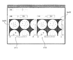
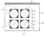
- FIG. 5A is a first diagram illustrating a display example of a plate view.
- FIG. 5B is a second diagram illustrating a display example of a plate view.
- FIG. 5A is a first diagram illustrating a display example of a plate view.
- FIG. 6A is a first diagram illustrating a display example of an enlarged plate view.
- FIG. 6B is a second diagram illustrating a display example of the enlarged plate view.
- FIG. 7A is a first diagram illustrating the principle of creating a contour line.
- FIG. 7B is a second diagram illustrating the principle of creating a contour line.
- FIG. 7C is a third diagram illustrating the principle of creating a contour line.
- FIG. 8 is a diagram illustrating a display example of a single view.
- FIG. 9A is a first diagram illustrating a display example of an enlarged single view.
- FIG. 9B is a second diagram illustrating a display example of an enlarged single view.
- FIG. 10A is a first diagram illustrating another display example of the single view.
- FIG. 10B is a second diagram illustrating another display example of the single view.
- the image display device 1 includes a plurality of, for example, 96 pieces (12 ⁇ 8 matrix array) into which liquids such as a culture solution, a medium, and a reagent (only a part of which is shown) are injected.
- liquids such as a culture solution, a medium, and a reagent (only a part of which is shown) are injected.
- the sample 11 (microplate) M in which the well W is formed is in contact with the lower peripheral edge of the sample (microplate) M to hold the microplate M in a substantially horizontal state
- a light source 12 provided on the holder 11
- An imaging unit 13 provided at the lower portion of the holder 11 and a control unit 10 that controls these to execute a predetermined operation are provided.
- coordinate axes are set as shown in FIG. 1A.
- the XY plane is a horizontal plane
- the Z axis is a vertical axis.
- each well W in the microplate M is typically about several mm.
- the dimensions of each part of the microplate M used in the experiment by the present inventors are shown.
- the diameter Dt of the opening Wt at the top of each well W is 6.69 mm
- the inner diameter Db of the well bottom surface Wb is 6.58 mm.
- the inner wall surface Ws of the well W is not a simple cylindrical surface, but has a tapered shape with the side surfaces inclined obliquely.
- the depth Dd of the wells W is 10.9 mm
- the arrangement pitch Dp of the plurality of wells W is 9 mm.
- the dimension of each part is a mere example, Comprising: The size of the microplate which this image display apparatus 1 makes object is not limited to these, It is arbitrary.
- the light source 12 is controlled by a light source control unit 112 provided in the control unit 10 and is collectively applied to a plurality of wells W from above the microplate M held by the holder 11 in accordance with a control command from the light source control unit 112. Then, the light L is irradiated.
- the irradiated light is visible light, and white light is particularly preferable.
- the imaging unit 13 functions as a camera that captures an image of the microplate M by receiving transmitted light Lt emitted from the light source 12 and transmitted below the microplate M held by the holder 11. .
- the imaging unit 13 is connected to a camera driving mechanism 113 provided in the control unit 10, and the camera driving mechanism 113 moves the imaging unit 13 along the horizontal plane (XY) along the lower surface of the microplate M held by the holder 11. Scanning movement within a plane).
- the imaging unit 13 can be scanned and moved along the lower surface of the microplate M.
- the imaging unit 13 moves relative to the microplate M.
- Image data captured by the imaging unit 13 is given to the image processing unit 114.
- the image processing unit 114 appropriately performs image processing on the image data from the imaging unit 13 or executes predetermined calculation processing based on the image data. Data before and after processing is stored and saved in the storage unit 115 as necessary.
- the detection processing unit 116 performs a predetermined detection process based on the image data given from the image processing unit 114, and detects a characteristic part included in the image.
- This detection process is a process of detecting an area in which the optical characteristics are different from the surrounding area in the image, for example, by analyzing the luminance data of the image. Further, by calculating the feature amount for the area, it is possible to classify what kind of origin and type the area is of. Since various techniques are known for the process of identifying and detecting a part having a certain feature from the image and the feature amount suitable for such a process, detailed description thereof is omitted here.
- the detection result by the detection processing unit 116 is also stored in the storage unit 115.
- the image processing unit 114 may perform image processing based on the detection result of the detection processing unit 116 as necessary.
- the image data subjected to appropriate image processing is given to a display unit 118 having display means such as a liquid crystal display, and the display unit 118 displays an image corresponding to the given image data and presents it to the user.
- the image display device 1 includes an input receiving unit 117 for receiving an operation instruction input from the user regarding the contents of the image processing, the display mode, and the like.
- the input receiving unit 117 is an input receiving unit such as a keyboard, a mouse, and a touch pad, or a combination of them.
- the input receiving unit 117 receives an instruction input from the user, and the control unit 10 reflects this in the operation of the apparatus. The function desired by the user is realized.
- the image display device 1 captures an optical image of an imaging target such as a liquid held in each well W and cells contained therein, or has a predetermined optical characteristic from the optical image.
- the present invention can be applied to the use of detecting a specific portion having an optical characteristic different from that of the liquid or the like held in the well W by utilizing the difference in the optical characteristic.
- it can be suitably used for the purpose of imaging a cell or a cell clump (spheroid) in a culture solution or a medium as an imaging object, or automatically detecting such a cell or the like by image processing.
- “liquid or the like” is a general term for liquid, gel-like or semi-fluid solid, and those that are injected into a well in a fluid state such as soft agar and then solidified.
- FIG. 2A and 2B are diagrams showing a more detailed configuration of the imaging unit.
- the imaging unit 13 outputs, for example, a CCD line sensor 131 that outputs an electrical signal corresponding to incident light, and light emitted from the bottom surface of the microplate M held by the holder 11.
- an imaging optical system 132 that forms an image on the light receiving surface.
- the imaging optical system 132 may include a plurality of optical components such as lenses, but here, for easy understanding, a single lens is representatively shown here.
- the line sensor 131 is a one-dimensional array of a large number of fine imaging elements 131a in the Y direction.
- at least one whole well W In the longitudinal direction, at least one whole well W, more preferably a plurality of (see FIG. The three wells W are configured to be included in the imaging range SR at a time.
- the length of the line sensor 131 in the Y direction is indicated by a symbol w
- the length of the visual field on the bottom surface of the microplate M is indicated by a symbol w ′.
- the scanning movement direction of the line sensor 131 by the camera driving mechanism 113 is the X direction.
- the line sensor 131 in which the image pickup devices are arranged along the Y direction is scanned and moved in the X direction along the bottom surface of the microplate M, thereby capturing a two-dimensional image of the microplate M viewed from the bottom surface side. Is possible.
- a large number of wells W formed on the microplate M can be sequentially imaged.
- the line sensor 131 can obtain a high-definition image because the pixel size of each image sensor is small.
- an imaging optical system 132 is configured so that a large number of imaging elements are arranged in a line and an optical image of each part of the well W is formed on each imaging element, and these are arranged at appropriate positions. More light from the well W is incident on the line sensor 131. By doing so, the time required to image one well W is shortened. Thereby, imaging about many wells W can be performed at high speed. If an image of the entire microplate M is acquired in this way in advance, then the captured image is subjected to predetermined processing and displayed in various display modes described below, so that it can be displayed to the user. Various images will be presented in a manner according to the purpose.
- the imaging unit 13 images each well W of the microplate M in response to an operation instruction from the user via the input reception unit 117, and based on the image data.
- the image processing unit 114 and the detection processing unit 116 perform image processing and detection processing designated by the user, and the results are displayed on the display unit 118.
- the control unit 10 performs the series of processes described below, thereby realizing the above function.
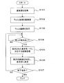
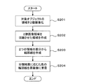
- FIG. 3 is a flowchart showing display processing in this image display apparatus.
- the imaging unit 13 operates to capture the entire microplate M and acquire original images for all wells W (step S101).
- An image obtained by scanning the entire microplate M includes images of all wells W as partial images. Among these, the part which imaged the microplate M surface other than the well W is unnecessary, and it is useless from the point of utilizing the display space of the display part 118 effectively. Therefore, only the image of the portion corresponding to the well W is extracted from the obtained image and rearranged to reconstruct the image (step S102).
- FIG. 4A and 4B are diagrams showing the principle of reconstruction of a well image.
- the image Im showing the entire microplate M is composed of a plurality of band images Ib imaged by the imaging unit 13 scanning and moving with respect to the microplate M. Only partial images Ip corresponding to the respective wells W arranged in a matrix are cut out from the whole image Im, and as shown in FIG. 4B, well images Iw reconstructed by arranging the cut out partial images Ip are obtained. Since the diameter and arrangement pitch of each well W in the microplate M are known in advance, for example, it is possible to specify the region corresponding to each well W based on the coordinate position in the entire image Im. Alternatively, since the region corresponding to each well W is a substantially circular shape having a known size, the region corresponding to such a well W can also be specified by extracting a region corresponding to such a condition by image analysis. .
- the partial image Ip only a substantially circular area corresponding to each well W may be cut out, or as shown in FIG. 4A, the partial image Ip may be cut out by a rectangle including a circular area corresponding to the well W. It may be an image. In the latter case, a desired partial image Ip is obtained by cutting out a square region whose center is located at the center of gravity of the well W and whose length of one side is substantially equal to the diameter of the well W, that is, circumscribing the circular region of the well W. It is done.
- the positional relationship between the wells W in the reconstructed well image Iw is arranged to be the same as the positional relationship between the wells in the entire image Im, that is, the positional relationship between the wells W on the actual microplate M. . That is, in the whole image Im shown in FIG. 4A, wells Wa1, Wa2, Wa3,... Are arranged in order from the upper left corner to the right, and wells Wa1, Wb1, Wc1,. Are in order. As shown in FIG. 4B, also in the reconstructed well image Iw, partial images Ipa1, Ipa2, Ipa3,... Corresponding to wells Wa1, Wa2, Wa3,... Are arranged in order from the upper left corner to the right. .. And partial images Ipa1, Ipb1, Ipc1,... Corresponding to wells Wa1, Wb1, Wc1,... Are arranged in order from the upper left corner downward.
- Each of the partial images Ipa1, Ipa2, Ipa3,... Cut out from the entire image Im is treated as a well-unit original image corresponding to each of the wells Wa1, Wa2, Wa3,.
- the arrangement positions on the microplate M are associated as index information. Specifically, a row index of 1 to 12 is assigned to each well arranged in the horizontal direction (row direction) in FIG. 4B.
- column indexes A to H are assigned to the wells arranged in the vertical direction (column direction).
- each well can be identified by a combination of alphabets A to H and numbers 1 to 12.
- step S103 The whole well image Iw created in this way is displayed on the display unit 118 (step S103). Thereby, the user can confirm the outline of the captured image. In this state, the system waits until an instruction input regarding the display mode is given from the user (step S104).
- Various display modes that are effective for supporting the user's observation of the well W can be adopted, but a part thereof is illustrated here.
- the first element related to the display mode is whether to display the whole of the plurality of wells W arranged on the microplate M or to display each well W individually.
- One of the purposes of using this type of apparatus is, for example, to display images of a plurality of samples created by changing conditions for each well W on the same screen, and comparatively observe them.
- a display mode for simultaneously displaying images corresponding to a plurality of wells W is necessary.
- the arrangement of the wells W in the displayed image matches the actual arrangement on the microplate M, the user can easily grasp the relationship between the wells W.
- the captured whole image Im of the microplate M is displayed as it is, blank portions other than the wells on the microplate M reduce the use efficiency of the display area.
- a partial image Ip corresponding to each well W is cut out from the entire image Im of the microplate M, and a well image Iw formed by arranging them in the same arrangement as the arrangement on the microplate M can be displayed. To do.
- a display mode is referred to as “plate view” in this specification. In the plate view, it is not always necessary to display all the wells W. If necessary, only some of the wells W may be displayed while maintaining the arrangement.
- each well W there is a purpose of observing the image of each well W in more detail, and a function for selecting an arbitrary well W by the user and displaying only the well is also required.
- Such a display mode is referred to as “single view” in this specification.
- the second factor related to the display mode is the magnification of the image.
- magnification of the image For the user, there are both a case where the user wants to look down on the entire image and a case where he wants to enlarge a part of the image. Therefore, it is preferable to have a function of displaying an image enlarged or reduced to an arbitrary magnification.
- the third element related to the display mode relates to the mode of image processing for the displayed image. It is possible not only to display the captured original image as it is, but also to support the user's observation work more effectively by analyzing the image and adding and displaying various information based on the result. Become.
- Various image analysis techniques are known, and various analysis techniques can also be applied to this embodiment.
- a classification technique for classifying various objects included in an image according to their optical or geometric characteristics.
- the classification can be performed based on the feature amount of the object calculated.
- the criteria for classification the size, density, area, circumscribed circle diameter, circumscribed sphere volume, cell type estimated from them, etc. can be used alone or in appropriate combination.
- step S104 when one display mode is specified by an instruction input from the user from among a plurality of display modes specified by the combination of the above three types of elements (step S104), the specification is made.
- Image processing necessary for performing display in the displayed display mode is performed (step S105). More specifically, the image processing unit 114 and the detection processing unit 116 perform various kinds of analysis / classification processing on the image and image processing for processing the image based on the result thereof, and the partial image Ip corresponding to each well W. Is performed on a display target.
- each processed partial image is used as a material image, and the image processing unit 114 creates a display image arranged in the display area with a predetermined arrangement and magnification, and the display unit 118 displays the display image.
- Step S106 a new instruction input from the user is awaited (step S107), and if there is an end instruction, the process is terminated, while if there is a new mode instruction input, a process corresponding thereto is executed again.
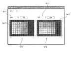
- 5A and 5B are diagrams showing display examples of the plate view.
- the work of preparing a sample in which the drug concentration in each well is regularly changed along the array and observing the sample is frequently used.
- the visibility of the array of each well is important.
- FIG. 5A shows an example of a plate view image corresponding to a microplate having 96 holes (12 holes ⁇ 8 rows).
- Each well is displayed not in the original image as it is, but in a color-coded state (gray scale display in the figure) based on the result classified based on the designated standard.
- the well images Iw11 and Iw12 displayed in the two display areas V11 and V12 correspond to the same image obtained by imaging the same microplate, but display contents are different because designated classification criteria are different from each other. Are generally different from each other.
- the well image Iw11 displayed in the left display area V11 has the area of the object included in each well as a reference parameter, as shown in the menu area M11 arranged above the display area V11. It is color-coded according to the classification result. That is, the area of each object included in each well is obtained by the image processing unit 114 and the detection processing unit 116, and each well is filled with a color corresponding to the average value of the areas obtained for each well. It is.
- the well image Iw12 displayed in the right display area V12 as shown in the upper menu area M12, it is based on the classification based on the diameter of the object (more specifically, the diameter of the circumscribed circle of the object) included in each well. Color coding is done.
- the user can be presented with an image in which the general tendency of the change in the shape of the object (cell agglomeration) that occurs between the wells as the drug concentration changes can be easily recognized. it can.
- an environment in which the user can perform observation work more efficiently can be provided.
- each well is filled with a color corresponding to the average value in the well of the parameter designated as the classification standard.
- the background of each well may be colored according to the value of the reference parameter.
- the user can switch display images in various ways by operating various setting functions displayed on the screen as necessary. That is, the user can click the menu area M11 on the screen or the “Setting” button to call up various setting menus and make settings. Further, the display magnification of the image can be increased / decreased by the “magnification” button.
- a new display mode is designated in this way, the processing from step S105 onward in FIG. 3 is re-executed, and an image in the designated display mode is displayed.
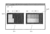
- the well image Iw21 displayed in the left display region V11 is an image binarized with a predetermined threshold with respect to the area of the object. Whether to display a multi-valued image or a binarized image, how to set a threshold value for binarization, and the like can be set by a setting menu.
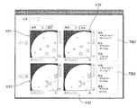
- FIG. 6A and 6B are diagrams showing display examples of the enlarged plate view.
- the example shown in FIG. 6A assumes a medium magnification (for example, 5 times), but the user can arbitrarily set the magnification by operating the operation bar (magnification bar) displayed at the top of the image. it can. At this time, the same magnification is applied to both of the enlarged well images Iw31 and Iw32 displayed in the two display areas V11 and V12. Even in the enlarged image, the positional relationship between the wells is maintained.
- a partial range of the well image is enlarged and displayed in the display areas V11 and V12, and outside the display area.
- An operation bar (scroll bar) is displayed so that the display range in the well image can be moved.
- the enlarged well images Iw31 and Iw32 always indicate the same range in the original well image. That is, when the scroll bar is operated in one of the images, the display ranges of the two enlarged well images Iw31 and Iw32 change at the same time.
- each well is displayed in a relatively large area
- the well is not filled in units of wells, and color coding and hatching based on the classification criteria are applied to each object included in each well. Processing such as is given.
- the user can create an environment for comparing wells that are close to each other (that is, the creation conditions are slightly different) while closely observing the distribution of objects in each well. Can be provided. By making it possible to continuously change the display range and magnification using the operation bar, comparative observation between wells can be easily performed.
- a pair of wells to be compared are displayed in the same positional relationship by linking the two images Iw31 and Iw32 so that the magnifications of the two images Iw32 and the display range of the whole well image match. Therefore, the user can observe each well while always comparing the analysis results based on different criteria.
- the example shown in FIG. 6B is a display example of the plate view when the enlargement magnification is set to the maximum.
- the enlargement magnification is selected so that approximately one well can be accommodated in each of the display areas V11 and V12.
- each object in the well is displayed while maintaining the color of the original image, and only its outline is colored based on the classification criteria (in the figure, the difference in the dot pitch of the broken line indicates the outline. Shows the difference in color).
- the outline of the object can be created as follows, for example.
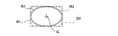
- FIG. 7A to FIG. 7C are diagrams showing the principle of outline creation.
- FIG. 7A is a flowchart showing a contour line creation process.
- the area of the object in the image is extracted as a binary image (step S201).
- the area of the object is filled with a predetermined pixel value.
- the region extracted as the binary image is contracted by a predetermined number of pixels by, for example, erosion processing in morphology processing (step S202).
- the number of pixels to be contracted is preferably selected to be a sufficiently small value with respect to the size of the region so that the shape of the region itself does not change greatly, and can be set to, for example, one pixel.
- the contracted region R2 is subtracted from the original binary image region R1 (step S203).
- the pixel value is canceled at the portion where the two regions R1 and R2 overlap, while at the peripheral portion, the outer peripheral portion (the hatched portion in FIG. 7B) of the original image region R1 by the number of contracted pixels. ) Will remain.
- the remaining part is combined with the original image and superimposed on the object as an outline of the object (step S204), so that the outline of the object can be highlighted.
- the object region in the original image, the binarized image region, and the posture and position of the image region obtained by contracting the region are aligned with each other. This is very important.
- rectangles S1 and S2 circumscribing these image regions R1 and R2 are virtually set, and the centroids G of the rectangles S1 and S2 are equal to each other.
- the image regions may be overlapped so that the corresponding sides are parallel to each other.
- the function of the plate view for displaying a plurality of wells W in the same arrangement as that on the microplate M has been described.
- the user can observe each well with the same operability as when directly observing the microplate M.
- it can observe from various viewpoints by displaying the classification results based on different criteria side by side.
- two types of classification results for the portion to be observed are always presented by linking the image magnification and display range in the two display areas.
- observation can be performed more efficiently.
- the aspect of the visual information attached to the image is automatically changed according to the change in magnification, it is possible to easily visually recognize the state of each well or each object in the well in each magnification image. Is possible.
- step S104 of FIG. 3 when the user selects a single view as the display mode and selects a well to be displayed, a single view display screen exemplified below is displayed.
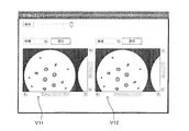
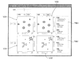
- FIG. 8 is a diagram showing a display example of a single view.
- the single view display screen four display areas V21, V22, V31, and V32 are arranged in a 2 ⁇ 2 matrix, and one partial image Ip corresponding to a single well is displayed in each display area.
- the upper two display areas V21 and V22 are images reflecting the results of classifying the same wells according to different criteria (in this example, the area and diameter of the object), specifically these reference parameters.
- An image in which the object is colored according to the value is displayed.
- the well displayed here is a well specified by the index information “A-1”, and the upper left corner in the plate image Ip shown in FIG. 4A. This corresponds to the well Wa1 located at.
- the user can change the well to be displayed by operating the pull-down menu.
- the area and diameter of the object are added to the original image corresponding to another well (in this example, the well Wc1 specified by the index “C-1”).
- Images reflecting the classification results based on the respective standards are displayed. That is, in this display mode, images representing the results of classifying the same wells with different criteria are displayed side by side in the left-right direction, while images representing the results of classifying different wells according to the same criteria are arranged in the vertical direction. Is displayed.
- text boxes TB1 and TB2 for displaying the analysis results in the corresponding wells by numerical values are provided at the right ends of the upper and lower stages.
- statistical information average value and standard deviation (SD) value
- SD standard deviation
- the user can observe an image while comparing the results of classifying two wells with two criteria, respectively. Further, the wells to be displayed and the classification criteria can be observed while appropriately switching them by operating the menu box. Further, more detailed information about each well can be obtained from the text information displayed in the text box. Thus, in this embodiment, detailed observation of wells, in particular, comparative observation between different wells or between different classification criteria of the same well can be efficiently performed.
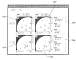
- FIG. 9A and FIG. 9B are diagrams showing a display example of an enlarged single view.
- FIG. 9A shows a display example when a medium (for example, 5 times) enlargement magnification is selected
- FIG. 9B shows a display example when the maximum magnification is selected.
- the display magnification of the image can be changed as appropriate in the single view, and the display range is linked in each display area when the whole well does not fit in the display range.
- the mode of the visual information given to the image to represent the classification result is automatically changed according to the change in display magnification.
- the user can simultaneously observe the results of image processing of the same well using different standards and between different wells using the same standard. Note that the statistical information displayed in the text boxes TB1 and TB2 represents the analysis result of one whole well, and does not change by changing the display magnification.
- FIG. 10A and 10B are diagrams showing other display examples of the single view.
- the number of detected objects that match the matching conditions specified by the user is displayed at the upper left of the area for each display area.
- this embodiment is an image display device for observing biological samples such as cells and cell clumps, for example, and allows a user to observe a plurality of images while comparing them.
- Various display functions are provided.
- the plate view function for displaying wells W on the microplate M generally, (1) Extracting images of well portions to be observed from an original image obtained by scanning the imaging unit with respect to the microplate, and displaying them in an arrangement according to the arrangement on the microplate. (2) About each well, the visual information (for example, color coding) according to the classification result based on the classification standard designated by the user is given and displayed. (3) The visual information can be changed by user designation. (4) Two kinds of classification results based on different classification criteria are displayed side by side in two display areas on the screen.
- each object in the well is displayed with visual information based on the classification result.
- the visual information to be given to the well or the object is automatically changed according to the designated display magnification. The function is realized.
- this embodiment it is possible to provide the user with an environment in which the sample can be efficiently observed from various viewpoints.
- comparison between different wells and comparison of results obtained by analyzing the same well from different viewpoints are facilitated.
- observing the state at the level of cell clumps rather than observing individual cells or their internal structures is useful for, for example, cell drug susceptibility testing.
- the microplate M corresponds to the “sample holding plate” of the present invention
- each well W corresponds to the “concave portion” of the present invention
- the partial image Ip corresponding to each well in the original image Im of the entire plate corresponds to the “original image” of the present invention
- the image after performing image processing on the image is the “material image” of the present invention. Is equivalent to.
- Each of the images shown in FIGS. 5, 6, 8 to 10 including this material image corresponds to the “display image” of the present invention.
- the detection processing unit 116 functions as the “specific part detection unit” and the “feature amount calculation unit” of the present invention, while the image processing unit 114 functions as the “visual information adding unit” of the present invention. These function as a whole and function as the “image processing means” of the present invention.
- the input receiving unit 117 functions as the “receiving unit” of the present invention
- the display unit 118 functions as the “displaying unit” of the present invention
- the imaging unit 13 functions as the “imaging unit” of the present invention.
- steps S104, S105, and S106 correspond to the “accepting process”, “image creating process”, and “display process” of the present invention, respectively.
- the present invention is not limited to the above-described embodiment, and various modifications other than those described above can be made without departing from the spirit of the present invention.
- the above-described embodiment is an image display device including an imaging unit that images a well formed on a microplate.
- the display processing of the present embodiment assists the user's observation by variously processing and displaying an image obtained by imaging the entire microplate. Therefore, even if the display mode is changed, imaging is performed again. Is not required. In this sense, it is not essential to include an imaging unit.
- the present invention also applies to an apparatus that receives image data captured by another imaging apparatus via an appropriate communication unit, processes the image data, and displays the processed image data. It is possible to apply.
- the objects in the well are classified based on criteria mainly related to the shape such as the area and diameter, but the classification criteria are not limited to these, and are used for observation of cells and biological tissues.
- Various classification criteria that can be applied are applicable. For example, an application is conceivable in which the cell type is comprehensively determined from the shape, color, size, etc. of the object, and the color is displayed for each cell type. Further, classification based on case learning using known samples may be applied.
- imaging is performed by relatively moving the line sensor 131 formed by one-dimensionally arranging the imaging elements with respect to the microplate M, but a CCD array in which the imaging elements are arranged in a two-dimensional matrix is used. May be used to perform imaging.
- the present invention can be particularly preferably applied to a field that requires observation of a sample held in each of a large number of wells, such as a microplate used in the medical / biological science field. Is not limited to the medical and biological science fields.
- Imaging unit imaging means
- Image processing unit visual information adding unit, image processing means
- Detection processing unit specific part detection unit, feature amount calculation unit, image processing means
- Input reception part reception means
- Display display means
- Ip partial image original image
- M microplate sample holding plate
- S104 Reception process S105 Image creation process
- S106 Display process W well (recessed part)
Abstract
Provided is an image display device or an image display method, said device or method having a display function that, in a technology that displays an image imaging a cavity in a specimen holding plate, enables a user to observe/compare the image from various viewpoints. Areas are extracted from an overall image that images the entirety of a microplate, each of said areas corresponding to each of multiple wells. For the image of each well, an image process is performed and a component image is created. Said image process is a process such as coloring or outline highlighting, and is based on a classification result resulting from a classification reference specified by the user. An image for display is created and displayed, said image for display arranging the component images in an arrangement that conforms to an arrangement sequence in the microplate. By arranging and displaying results classified by different classification references, comparative observation from different viewpoints is facilitated.
Description
この発明は、試料保持プレートの窪部を撮像した画像に所定の画像処理を施し、その結果を反映させた画像を表示する画像表示装置および画像表示方法に関するものである。
The present invention relates to an image display device and an image display method for displaying an image reflecting a result of performing predetermined image processing on an image obtained by imaging a recess of a sample holding plate.
医療や生物科学の実験においては、例えばウェルとも称される窪部を多数配列して設けたプレート状の器具の各ウェルに液体(例えば培養液)や培地等を注入し、ここで培養した細胞等を観察することが行われる。このような器具は、例えばマイクロプレート、マイクロタイタープレート等と呼ばれるものである。このような技術では、例えば試料に対する前処理や試薬の使用によって特定の分子を蛍光発光させるなどの方法が、従来から行われてきた。また近年では、試薬を用いず簡便で低コストな方法として、画像処理技術を利用して原画像を解析し表示する技術も検討されている。例えば特許文献1に記載の画像処理システムでは、複数の生細胞を観測試料としてその画像を撮像し、該画像を解析することによって認識した細胞領域に対しその特徴量に応じて色付けした画像を表示させるように構成されている。
In medical and biological science experiments, for example, a cell (culture medium) or culture medium is injected into each well of a plate-like instrument provided with a large number of depressions, also called wells, and cultured here Etc. are performed. Such an instrument is called, for example, a microplate or a microtiter plate. In such a technique, for example, a method of fluorescently emitting a specific molecule by pretreatment of a sample or use of a reagent has been conventionally performed. In recent years, as a simple and low-cost method without using a reagent, a technique for analyzing and displaying an original image using an image processing technique has been studied. For example, in the image processing system described in Patent Document 1, a plurality of living cells are taken as observation samples, the image is captured, and an image colored according to the feature amount is displayed for a cell region recognized by analyzing the image. It is configured to let you.
上記従来技術は、二次元的に培養された試料を個々の細胞が認識できる程度の高解像度で撮像した画像を対象とするものである。一方、より生体内の状況に近い状態での実験を行うために、三次元的に培養された細胞の集塊を観察の対象とすることがある。このような場合、個々の細胞レベルの情報よりも細胞集塊に関する情報が重要である。また、このような細胞集塊レベルでの画像の評価方法については未だ基準が確立されていない。そのため、予め定められたルールで画像を解析するだけでなく、ユーザが種々の観点から画像を観察・比較することができるような表示機能を有する装置が切望されている。しかしながら、上記特許文献1に記載のものをはじめ、従来の技術においては、このようなニーズに応えることのできる機能を備えたものはなかった。
The above prior art is intended for an image obtained by imaging a sample cultured two-dimensionally with a high resolution that can be recognized by individual cells. On the other hand, in order to conduct an experiment in a state closer to the state in a living body, an agglomeration of three-dimensionally cultured cells may be an object of observation. In such a case, information about the cell cluster is more important than information at the individual cell level. In addition, a standard has not been established yet for such an image evaluation method at the cell clump level. Therefore, an apparatus having a display function that allows a user to observe and compare images from various viewpoints as well as to analyze images based on predetermined rules is desired. However, none of the conventional techniques including the one described in Patent Document 1 has a function capable of meeting such needs.
この発明は上記課題に鑑みなされたものであり、試料保持プレートの窪部を撮像した画像を表示する技術において、上記のようなユーザの要求に応えることのできる画像を表示する画像表示装置または画像表示方法を提供しようとするものである。
The present invention has been made in view of the above problems, and in the technology for displaying an image obtained by imaging the recess of the sample holding plate, an image display device or an image for displaying an image that can meet the user's request as described above It is intended to provide a display method.
この発明の一の態様は、試料を保持するための窪部が複数配列された試料保持プレートの前記窪部を撮像した画像を表示する画像表示装置であって、上記目的を達成するため、一の前記窪部を撮像した原画像に対して当該原画像の内容に応じた視覚情報を付与する画像処理を施した素材画像を作成するとともに、互いに異なる複数の前記素材画像を配した表示用画像を作成する画像処理手段と、前記表示用画像を表示する表示手段とを備えている。
One aspect of the present invention is an image display device that displays an image obtained by imaging the recess of a sample holding plate in which a plurality of recesses for holding a sample are arranged. In order to achieve the above object, An image for display in which a raw material image obtained by performing image processing for giving visual information according to the content of the original image to the original image obtained by imaging the depression is provided, and a plurality of different raw material images are arranged Image processing means for generating the image and display means for displaying the display image.
また、この発明の他の態様は、試料を保持するための窪部が複数配列された試料保持プレートの前記窪部を撮像した画像を表示する画像表示方法であって、上記目的を達成するため、一の前記窪部を撮像した原画像に対して当該原画像の内容に応じた視覚情報を付与する画像処理を施した素材画像を作成するとともに、互いに異なる複数の前記素材画像を同一フレーム内に配した表示用画像を作成する画像作成工程と、前記表示用画像を表示する表示工程とを備えている。
According to another aspect of the present invention, there is provided an image display method for displaying an image obtained by imaging the depression of a sample holding plate in which a plurality of depressions for holding a sample are arranged. Creating a material image obtained by performing image processing for providing visual information corresponding to the content of the original image to the original image obtained by imaging one of the depressions, and arranging a plurality of different material images in the same frame An image creating step for creating a display image arranged on the display, and a display step for displaying the display image.
これらの発明において、前記表示用画像は、(1)互いに異なる前記窪部に対応する前記原画像のそれぞれに対して同一の画像処理が施された複数の前記素材画像の組、(2)同一の前記原画像に対して互いに異なる画像処理が施された複数の前記素材画像の組、のうち少なくとも一方の組を含むものである。このように、画像処理に基づく視覚情報が付与された素材画像を複数配した画像を提示することで、この発明では、窪部を撮像してなる画像を種々の観点から比較したいというユーザの要求に応じた画像表示装置または画像表示方法を提供することが可能となっている。すなわち、上記(1)の素材画像を複数配置した画像を表示することによって、例えば異なる条件で作成した試料を同一条件で比較観察することができるようになる。また、上記(2)の素材画像を複数配置した画像を表示することによって、同一の試料を同時に異なる観点から比較観察することができるようになる。
In these inventions, the display image is (1) a set of a plurality of material images obtained by performing the same image processing on each of the original images corresponding to the different recesses, and (2) the same. The original image includes at least one of a plurality of sets of the material images obtained by performing different image processing on the original image. In this way, by presenting an image in which a plurality of material images to which visual information based on image processing has been assigned is presented, in the present invention, a user's request to compare an image formed by imaging a depression from various viewpoints It is possible to provide an image display device or an image display method according to the above. That is, by displaying an image in which a plurality of the material images (1) are arranged, for example, samples prepared under different conditions can be compared and observed under the same conditions. Further, by displaying an image in which a plurality of material images (2) are arranged, the same sample can be simultaneously compared and observed from different viewpoints.
ここで、素材画像に視覚情報を付与する手段としては、例えば、色分け、塗り潰し、明度の変更、輪郭の強調、囲み枠やポインタの付加、テキスト情報の付加などによるものやそれらの組み合わせによるものを用いることが可能である。
Here, as means for giving visual information to the material image, for example, color coding, painting, changing brightness, emphasizing contours, adding a frame or pointer, adding text information, or a combination thereof It is possible to use.
本発明では、例えば、素材画像の選択、および、画像処理の内容の選択、のうち少なくとも一方に関するユーザからの指示入力に応じた表示用画像が作成されるようにしてもよい。このような構成とすることにより、ユーザの多様な要求に応じた種々の画像を適宜表示して、ユーザの作業を効率的に支援することが可能となる。
In the present invention, for example, a display image corresponding to an instruction input from a user regarding at least one of selection of a material image and selection of contents of image processing may be created. With such a configuration, it is possible to appropriately display various images according to various requests of the user and efficiently support the user's work.
また、上記した画像表示装置において、例えば、画像処理手段は、原画像内で特定の光学的特性を有する特定部位を検出する特定部位検出部と、検出された特定部位の特徴量を算出する特徴量算出部と、算出された特徴量の値に応じた視覚情報を原画像に付与する視覚情報付与部とを備えるようにしてもよい。このようにすると、画像内に含まれる特定の特徴を有する部位(特定部位)を他の部分と容易に区別することが可能となる表示用画像をユーザに提示することができる。
In the above-described image display device, for example, the image processing unit includes a specific part detection unit that detects a specific part having specific optical characteristics in the original image, and a feature that calculates a feature amount of the detected specific part. You may make it provide the amount calculation part and the visual information provision part which provides the visual information according to the value of the calculated feature-value to an original image. In this way, it is possible to present to the user a display image that makes it possible to easily distinguish a part (specific part) having a specific feature included in the image from other parts.
この場合において、視覚情報付与部は、例えば原画像内の特定部位に対応する位置に、当該特定部位について算出された特徴量の値に応じた視覚情報を付与するようにしてもよい。これにより、ユーザは特定部位の分布状況を容易に把握することができ、しかも複数の素材画像間での分布状態の比較も容易に行うことが可能となる。
In this case, the visual information giving unit may give visual information corresponding to the value of the feature amount calculated for the specific part at a position corresponding to the specific part in the original image, for example. As a result, the user can easily grasp the distribution status of the specific part, and can easily compare the distribution status among a plurality of material images.
また、この発明において、例えば、同一の原画像に対して互いに異なる特徴量に基づく視覚情報がそれぞれ付与された複数の素材画像を含むように、表示用画像が作成されてもよい。このようにすると、1つの試料を異なる観点から処理した素材画像が同時に表示されるため、ユーザは当該試料の観察をより効率よく行うことが可能となる。
Further, in the present invention, for example, the display image may be created so as to include a plurality of material images each provided with visual information based on different feature amounts with respect to the same original image. In this way, since the material images obtained by processing one sample from different viewpoints are displayed at the same time, the user can observe the sample more efficiently.
また例えば、互いに異なる窪部に対応する複数の素材画像を試料保持プレートにおける各窪部の配列順序に対応させて配置した表示用画像が作成されるようにしてもよい。このようにすると、ユーザは表示された素材画像相互の関係性を容易に把握することが可能であり、比較観察を効率的に行うことができる。
Also, for example, a display image may be created in which a plurality of material images corresponding to different recesses are arranged in correspondence with the arrangement order of the recesses on the sample holding plate. In this way, the user can easily grasp the relationship between displayed material images, and can efficiently perform comparative observation.
また例えば、表示用画像における素材画像の表示倍率が変更設定可能とされ、設定された表示倍率に応じて素材画像に付与する視覚情報が異なるようにしてもよい。こうすることで、ユーザにとってより視認しやすい表示用画像を提示することが可能となる。
Also, for example, the display magnification of the material image in the display image can be changed and set, and the visual information added to the material image may be different according to the set display magnification. This makes it possible to present a display image that is easier for the user to visually recognize.
また例えば、同一の原画像内の同一の一部領域に互いに異なる画像処理を施した、複数の素材画像を含む表示用画像が作成されるようにしてもよい。観察の目的によっては、ユーザが原画像のうちの一部領域のみを表示させることを望む場合がある。このような場合に、原画像の一部領域に対応する複数の素材画像が互いに同一領域を表すものとなっていれば、ユーザによる観察をより効率的に支援することが可能となる。
Further, for example, a display image including a plurality of material images obtained by performing different image processing on the same partial region in the same original image may be created. Depending on the purpose of observation, the user may desire to display only a partial region of the original image. In such a case, if a plurality of material images corresponding to a partial area of the original image represent the same area, it is possible to support the user's observation more efficiently.
また例えば、素材画像と、当該素材画像の内容に関する文字情報とを含む表示用画像が作成されようにしてもよい。こうすることで、画像内容に関するより詳細な情報をユーザに提供することができる。
Also, for example, a display image including a material image and character information related to the content of the material image may be created. In this way, more detailed information regarding the image content can be provided to the user.
また例えば、本発明は、試料保持プレートに対して撮像素子を相対的に走査移動させて原画像を撮像する撮像手段を備えてもよい。このように構成された画像表示装置では、原画像の撮像からそれに対する画像処理および表示までの一連の処理を単一の装置で完結させることができる。また、試料保持プレートに対する撮像素子の走査移動により撮像を行うことで試料保持プレートの広範囲を高い分解能で撮像することができるので、ユーザに高精細な画像を提示することができる。
Further, for example, the present invention may include an image pickup unit that picks up an original image by scanning and moving the image pickup device relative to the sample holding plate. In the image display apparatus configured as described above, a series of processes from the capture of an original image to image processing and display for the original image can be completed with a single apparatus. In addition, since a wide range of the sample holding plate can be imaged with high resolution by performing imaging by scanning movement of the imaging device with respect to the sample holding plate, a high-definition image can be presented to the user.
また、この発明では、例えば細胞または微生物を含んだ透明な液体またはゲル体を試料として保持する窪部を撮像した画像を、原画像として用いてもよい。このような試料を用いる実験においては、条件を異ならせた複数の試料を作成してそれらの差異を比較するという過程が多用されている。本発明をこのような試料の観察に適用することで、ユーザの作業を大幅に効率化・簡略化することが可能である。
Further, in the present invention, for example, an image obtained by imaging a recess that holds a transparent liquid or gel body containing cells or microorganisms as a sample may be used as an original image. In an experiment using such a sample, a process of making a plurality of samples with different conditions and comparing the differences is frequently used. By applying the present invention to observation of such a sample, it is possible to greatly improve and simplify the user's work.
この発明によれば、試料が保持された試料保持プレートの窪部を撮像した原画像に所定の画像処理が施された素材画像を複数配した表示用画像をユーザに提示することで、試料の比較観察に好適な画像を望むユーザの要求に応えることができる。
この発明の前記ならびにその他の目的と新規な特徴は、添付図面を参照しながら次の詳細な説明を読めば、より完全に明らかとなるであろう。ただし、図面は専ら解説のためのものであって、この発明の範囲を限定するものではない。 According to the present invention, a display image in which a plurality of material images obtained by performing predetermined image processing on an original image obtained by capturing an image of a recess of a sample holding plate that holds a sample is presented to a user. It is possible to meet the demand of a user who desires an image suitable for comparative observation.
The above and other objects and novel features of the present invention will become more fully apparent when the following detailed description is read with reference to the accompanying drawings. However, the drawings are for explanation only and do not limit the scope of the present invention.
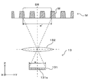
図1Aおよび図1Bはこの発明にかかる画像表示装置の一実施形態の概略構成を示す図である。この画像表示装置1は、図1Aに示すように、それぞれに例えば培養液、培地、試薬などの液体等(一部のみ図示)が注入された複数の、例えば96個(12×8のマトリクス配列)のウェルWを形成されたサンプル(マイクロプレート)Mの下面周縁部に当接して該マイクロプレートMを略水平状態に保持するホルダ11と、該ホルダ11の上部に設けられた光源12と、ホルダ11の下部に設けられた撮像ユニット13と、これらを司って所定の動作を実行させる制御部10とを備えている。以下の説明のために図1Aに示す通りに座標軸を設定する。X-Y平面は水平面であり、Z軸は鉛直軸である。
1A and 1B are diagrams showing a schematic configuration of an embodiment of an image display apparatus according to the present invention. As shown in FIG. 1A, the image display device 1 includes a plurality of, for example, 96 pieces (12 × 8 matrix array) into which liquids such as a culture solution, a medium, and a reagent (only a part of which is shown) are injected. ) Of the sample 11 (microplate) M in which the well W is formed is in contact with the lower peripheral edge of the sample (microplate) M to hold the microplate M in a substantially horizontal state, a light source 12 provided on the holder 11, An imaging unit 13 provided at the lower portion of the holder 11 and a control unit 10 that controls these to execute a predetermined operation are provided. For the following description, coordinate axes are set as shown in FIG. 1A. The XY plane is a horizontal plane, and the Z axis is a vertical axis.
マイクロプレートMにおける各ウェルWの直径および深さは代表的には数mm程度である。一例として、本願発明者が実験において用いたマイクロプレートMの各部の寸法を示す。図1Bに示すように、各ウェルWの上部における開口Wtの直径Dtが6.69mmである一方、ウェル底面Wbの内径Dbが6.58mmである。これからわかるように、ウェルWの内壁面Wsは単純な円筒面ではなく、側面が斜めに傾斜したテーパー形状となっている。また、ウェルWの深さDdは10.9mmであり、複数ウェルWの配列ピッチDpは9mmである。なお、各部の寸法は単なる例であって、この画像表示装置1が対象とするマイクロプレートのサイズはこれらに限定されるものではなく任意である。
The diameter and depth of each well W in the microplate M is typically about several mm. As an example, the dimensions of each part of the microplate M used in the experiment by the present inventors are shown. As shown in FIG. 1B, the diameter Dt of the opening Wt at the top of each well W is 6.69 mm, while the inner diameter Db of the well bottom surface Wb is 6.58 mm. As can be seen, the inner wall surface Ws of the well W is not a simple cylindrical surface, but has a tapered shape with the side surfaces inclined obliquely. The depth Dd of the wells W is 10.9 mm, and the arrangement pitch Dp of the plurality of wells W is 9 mm. In addition, the dimension of each part is a mere example, Comprising: The size of the microplate which this image display apparatus 1 makes object is not limited to these, It is arbitrary.
光源12は、制御部10に設けられた光源制御部112によって制御され、光源制御部112からの制御指令に応じてホルダ11に保持されたマイクロプレートMの上方から複数のウェルWに対して一括して光Lを照射する。照射される光は可視光であり、特に白色光が好ましい。
The light source 12 is controlled by a light source control unit 112 provided in the control unit 10 and is collectively applied to a plurality of wells W from above the microplate M held by the holder 11 in accordance with a control command from the light source control unit 112. Then, the light L is irradiated. The irradiated light is visible light, and white light is particularly preferable.
撮像ユニット13は、光源12から出射されてホルダ11に保持されたマイクロプレートMの下方に透過してくる透過光Ltを受光することでマイクロプレートMの画像を撮像するカメラとして機能するものである。撮像ユニット13は制御部10に設けられたカメラ駆動機構113に連結されており、カメラ駆動機構113は、ホルダ11に保持されたマイクロプレートMの下面に沿って撮像ユニット13を水平面(X-Y平面)内で走査移動させる。
The imaging unit 13 functions as a camera that captures an image of the microplate M by receiving transmitted light Lt emitted from the light source 12 and transmitted below the microplate M held by the holder 11. . The imaging unit 13 is connected to a camera driving mechanism 113 provided in the control unit 10, and the camera driving mechanism 113 moves the imaging unit 13 along the horizontal plane (XY) along the lower surface of the microplate M held by the holder 11. Scanning movement within a plane).
すなわち、この実施形態では、撮像ユニット13がマイクロプレートMの下面に沿って走査移動可能となっている。なお、ここでは撮像ユニット13がマイクロプレートMに対して移動するが、撮像ユニット13とマイクロプレートMとの間の相対移動が実現されれば足り、この意味でマイクロプレートMを撮像ユニット13に対して移動させるようにしてもよい。
That is, in this embodiment, the imaging unit 13 can be scanned and moved along the lower surface of the microplate M. Here, the imaging unit 13 moves relative to the microplate M. However, it is sufficient that the relative movement between the imaging unit 13 and the microplate M is realized. In this sense, the microplate M is moved relative to the imaging unit 13. You may make it move.
撮像ユニット13により撮像された画像データは画像処理部114に与えられる。画像処理部114は、撮像ユニット13からの画像データに対して適宜画像処理を施したり、画像データに基づく所定の演算処理を実行する。処理前後のデータは必要に応じて記憶部115に記憶保存される。また、検出処理部116は、画像処理部114から与えられる画像データに基づき所定の検出処理を行って、画像に含まれる特徴的な部位を検出する。この検出処理は、例えば画像の輝度データを解析することによって当該画像の中で光学的特性がその周囲領域とは異なる領域を検出する処理である。さらに、当該領域について特徴量を算出することにより、当該領域がどのような起源・種類のものであるかの分類が可能である。このように画像からある特徴を有する部位を識別し検出する処理や、そのような処理に好適な特徴量については種々の技術が公知であるので、ここでは詳しい説明を省略する。
Image data captured by the imaging unit 13 is given to the image processing unit 114. The image processing unit 114 appropriately performs image processing on the image data from the imaging unit 13 or executes predetermined calculation processing based on the image data. Data before and after processing is stored and saved in the storage unit 115 as necessary. Further, the detection processing unit 116 performs a predetermined detection process based on the image data given from the image processing unit 114, and detects a characteristic part included in the image. This detection process is a process of detecting an area in which the optical characteristics are different from the surrounding area in the image, for example, by analyzing the luminance data of the image. Further, by calculating the feature amount for the area, it is possible to classify what kind of origin and type the area is of. Since various techniques are known for the process of identifying and detecting a part having a certain feature from the image and the feature amount suitable for such a process, detailed description thereof is omitted here.
検出処理部116による検出結果も記憶部115に保存される。また、後述するように、画像処理部114は、必要に応じて検出処理部116による検出結果に基づいた画像処理を行う場合がある。そして、適宜の画像処理が施された画像データは例えば液晶ディスプレイ等の表示手段を有する表示部118に与えられ、表示部118は与えられた画像データに対応する画像を表示してユーザに提示する。さらに、この画像表示装置1は、画像処理の内容や表示の態様等についてユーザからの操作指示入力を受け付けるための入力受付部117を有している。入力受付部117は、例えばキーボード、マウス、タッチパッド等の入力受付手段またはそれらを適宜組み合わせたものであり、ユーザからの指示入力を受け付けて制御部10がこれを装置の動作に反映させることで、ユーザが所望する機能を実現する。
The detection result by the detection processing unit 116 is also stored in the storage unit 115. As will be described later, the image processing unit 114 may perform image processing based on the detection result of the detection processing unit 116 as necessary. Then, the image data subjected to appropriate image processing is given to a display unit 118 having display means such as a liquid crystal display, and the display unit 118 displays an image corresponding to the given image data and presents it to the user. . Further, the image display device 1 includes an input receiving unit 117 for receiving an operation instruction input from the user regarding the contents of the image processing, the display mode, and the like. The input receiving unit 117 is an input receiving unit such as a keyboard, a mouse, and a touch pad, or a combination of them. The input receiving unit 117 receives an instruction input from the user, and the control unit 10 reflects this in the operation of the apparatus. The function desired by the user is realized.
この画像表示装置1は、各ウェルWに保持された液体等およびその中に含まれる細胞等の撮像対象物の光学像を撮像したり、その光学像から所定の光学的特徴を有する、より具体的にはウェルWに保持された液体等とは異なる光学的特性を有する特異な部分をその光学的特性の差異を利用して検出するという用途に適用することができる。例えば、培養液や培地中の細胞や細胞集塊(スフェロイド)を撮像対象物として撮像したり、さらに画像処理によりそのような細胞等を自動的に検出する目的に好適に使用することができる。本明細書において「液体等」とは、液体、ゲル状のまたは半流動性を有する固体、および、例えば軟寒天のように流動性を有する状態でウェルに注入されその後固化するものの総称である。
The image display device 1 captures an optical image of an imaging target such as a liquid held in each well W and cells contained therein, or has a predetermined optical characteristic from the optical image. Specifically, the present invention can be applied to the use of detecting a specific portion having an optical characteristic different from that of the liquid or the like held in the well W by utilizing the difference in the optical characteristic. For example, it can be suitably used for the purpose of imaging a cell or a cell clump (spheroid) in a culture solution or a medium as an imaging object, or automatically detecting such a cell or the like by image processing. In this specification, “liquid or the like” is a general term for liquid, gel-like or semi-fluid solid, and those that are injected into a well in a fluid state such as soft agar and then solidified.
図2Aおよび図2Bは撮像部のより詳細な構成を示す図である。図2Aに示すように、撮像ユニット13は、入射光に応じた電気信号を出力する例えばCCDによるラインセンサ131と、ホルダ11に保持されたマイクロプレートMの底面から出射される光をラインセンサ131の受光面に結像させる結像光学系132とを備えている。結像光学系132はレンズ等の光学部品を複数備えるものであってよいが、ここでは理解を容易にするために代表的に単一のレンズによって示している。
2A and 2B are diagrams showing a more detailed configuration of the imaging unit. As shown in FIG. 2A, the imaging unit 13 outputs, for example, a CCD line sensor 131 that outputs an electrical signal corresponding to incident light, and light emitted from the bottom surface of the microplate M held by the holder 11. And an imaging optical system 132 that forms an image on the light receiving surface. The imaging optical system 132 may include a plurality of optical components such as lenses, but here, for easy understanding, a single lens is representatively shown here.
ラインセンサ131は多数の微細な撮像素子131aをY方向に一次元配列したものであり、その長手方向には結像光学系132を介して少なくとも1つのウェルW全体、より望ましくは複数の(図では3つの)ウェルWを一度に撮像範囲SRに含めることができるよう構成されている。図では、ラインセンサ131のY方向長さを符号w、これによるマイクロプレートMの底面における視野のY方向長さを符号w’により表している。
The line sensor 131 is a one-dimensional array of a large number of fine imaging elements 131a in the Y direction. In the longitudinal direction, at least one whole well W, more preferably a plurality of (see FIG. The three wells W are configured to be included in the imaging range SR at a time. In the figure, the length of the line sensor 131 in the Y direction is indicated by a symbol w, and the length of the visual field on the bottom surface of the microplate M is indicated by a symbol w ′.
また、図2Bに示すように、カメラ駆動機構113によるラインセンサ131の走査移動方向はX方向である。このように、Y方向に沿って撮像素子が配列されたラインセンサ131をマイクロプレートMの底面に沿ってX方向に走査移動させることで、底面側から見たマイクロプレートMの二次元画像を撮像することが可能である。また、ラインセンサ131のY方向位置を異ならせて上記走査移動を繰り返すことで、マイクロプレートMに形成された多数のウェルWを順次撮像することができる。
Further, as shown in FIG. 2B, the scanning movement direction of the line sensor 131 by the camera driving mechanism 113 is the X direction. In this way, the line sensor 131 in which the image pickup devices are arranged along the Y direction is scanned and moved in the X direction along the bottom surface of the microplate M, thereby capturing a two-dimensional image of the microplate M viewed from the bottom surface side. Is possible. In addition, by repeating the scanning movement with the line sensor 131 at different positions in the Y direction, a large number of wells W formed on the microplate M can be sequentially imaged.
ラインセンサ131は各撮像素子の画素サイズが小さいため高精細の画像を得ることが可能である。また、多数の撮像素子をライン状に配列するとともに各撮像素子にウェルW各部の光学像を結像させるように結像光学系132を構成してそれらを適切な位置に配置し、1つまたはそれ以上のウェルWからの光をラインセンサ131に入射させる。こうすることで、1つのウェルWを撮像するのに必要な時間が短くなる。これにより、多数のウェルWについての撮像を高速で行うことができる。このようにしてマイクロプレートM全体の画像を予め取得しておけば、以後は撮像された画像に所定の加工が施され以下に説明する種々の表示モードで表示されることにより、ユーザに対して、その目的に応じた態様で種々の画像が提示されることとなる。
The line sensor 131 can obtain a high-definition image because the pixel size of each image sensor is small. In addition, an imaging optical system 132 is configured so that a large number of imaging elements are arranged in a line and an optical image of each part of the well W is formed on each imaging element, and these are arranged at appropriate positions. More light from the well W is incident on the line sensor 131. By doing so, the time required to image one well W is shortened. Thereby, imaging about many wells W can be performed at high speed. If an image of the entire microplate M is acquired in this way in advance, then the captured image is subjected to predetermined processing and displayed in various display modes described below, so that it can be displayed to the user. Various images will be presented in a manner according to the purpose.
上記のように構成された画像表示装置1では、入力受付部117を介したユーザからの操作指示に応じて、撮像ユニット13がマイクロプレートMの各ウェルWを撮像し、その画像データに基づいて、画像処理部114および検出処理部116がユーザにより指定された画像処理および検出処理を施して、その結果が表示部118に表示される。ユーザから撮像指示が与えられたとき、制御部10が以下に説明する一連の処理を行うことで、上記機能が実現される。
In the image display device 1 configured as described above, the imaging unit 13 images each well W of the microplate M in response to an operation instruction from the user via the input reception unit 117, and based on the image data. The image processing unit 114 and the detection processing unit 116 perform image processing and detection processing designated by the user, and the results are displayed on the display unit 118. When the imaging instruction is given from the user, the control unit 10 performs the series of processes described below, thereby realizing the above function.
図3はこの画像表示装置における表示処理を示すフローチャートである。ユーザから撮像指示が与えられると、撮像ユニット13が動作してマイクロプレートMの全体を撮像し、全てのウェルWについての原画像を取得する(ステップS101)。マイクロプレートMの全体を走査して撮像した画像は全てのウェルWの画像を部分画像として含んでいる。このうち、ウェルW以外のマイクロプレートM表面を撮像した部分は不要であり、また表示部118の表示スペースを有効に活用するという点からは無駄なものである。そこで、得られた画像から以下のようにしてウェルWに相当する部分の画像のみを抽出し並べ直すことにより、画像の再構成を行う(ステップS102)。
FIG. 3 is a flowchart showing display processing in this image display apparatus. When an imaging instruction is given from the user, the imaging unit 13 operates to capture the entire microplate M and acquire original images for all wells W (step S101). An image obtained by scanning the entire microplate M includes images of all wells W as partial images. Among these, the part which imaged the microplate M surface other than the well W is unnecessary, and it is useless from the point of utilizing the display space of the display part 118 effectively. Therefore, only the image of the portion corresponding to the well W is extracted from the obtained image and rearranged to reconstruct the image (step S102).
図4Aおよび図4Bはウェル画像の再構成の原理を示す図である。図4Aに示すように、マイクロプレートMの全体を示す画像Imは、マイクロプレートMに対して撮像ユニット13が走査移動することで撮像された複数のバンド画像Ibからなる。この全体画像Imから、マトリクス状に配された各ウェルWに対応する部分画像Ipのみを切り出し、図4Bに示すように、切り出した部分画像Ipを並べて再構成されたウェル画像Iwを得る。マイクロプレートMにおける各ウェルWの口径や配列ピッチは予めわかっているから、例えば、全体画像Im内における座標位置に基づいて、各ウェルWに対応する領域を特定することが可能である。または、各ウェルWに対応する領域がサイズ既知の略円形であることから、画像解析によってそのような条件に該当する領域を抽出することによっても、ウェルWに対応する領域を特定することができる。
4A and 4B are diagrams showing the principle of reconstruction of a well image. As shown in FIG. 4A, the image Im showing the entire microplate M is composed of a plurality of band images Ib imaged by the imaging unit 13 scanning and moving with respect to the microplate M. Only partial images Ip corresponding to the respective wells W arranged in a matrix are cut out from the whole image Im, and as shown in FIG. 4B, well images Iw reconstructed by arranging the cut out partial images Ip are obtained. Since the diameter and arrangement pitch of each well W in the microplate M are known in advance, for example, it is possible to specify the region corresponding to each well W based on the coordinate position in the entire image Im. Alternatively, since the region corresponding to each well W is a substantially circular shape having a known size, the region corresponding to such a well W can also be specified by extracting a region corresponding to such a condition by image analysis. .
部分画像Ipとしては、各ウェルWに対応する略円形の領域のみが切り出されたものであってもよく、また図4Aに示すように、ウェルWに対応する円形領域を含む矩形によって切り出された画像であってもよい。後者の場合、ウェルWの重心位置を中心とし1辺の長さがウェルWの直径と略等しい、つまりウェルWの円形領域に外接する正方形の領域を切り出すことによって、所望の部分画像Ipが得られる。
As the partial image Ip, only a substantially circular area corresponding to each well W may be cut out, or as shown in FIG. 4A, the partial image Ip may be cut out by a rectangle including a circular area corresponding to the well W. It may be an image. In the latter case, a desired partial image Ip is obtained by cutting out a square region whose center is located at the center of gravity of the well W and whose length of one side is substantially equal to the diameter of the well W, that is, circumscribing the circular region of the well W. It is done.
再構成されたウェル画像Iwにおける各ウェルW相互の位置関係は、全体画像Imにおける各ウェルの位置関係、つまり実際のマイクロプレートM上におけるウェルW相互の位置関係と同じになるように配置される。すなわち、図4Aに示す全体画像Imにおいては、左上隅から右方に向かってウェルWa1,Wa2,Wa3,…が順に並んでおり、また左上隅から下方に向かってウェルWa1,Wb1,Wc1,…が順に並んでいる。図4Bに示すように、再構成されたウェル画像Iwにおいても、ウェルWa1,Wa2,Wa3,…に相当する部分画像Ipa1,Ipa2,Ipa3,…が左上隅から右方に向かって順に並ぶように配列され、またウェルWa1,Wb1,Wc1,…に相当する部分画像Ipa1,Ipb1,Ipc1,…が左上隅から下方に向かって順に並ぶように配列される。
The positional relationship between the wells W in the reconstructed well image Iw is arranged to be the same as the positional relationship between the wells in the entire image Im, that is, the positional relationship between the wells W on the actual microplate M. . That is, in the whole image Im shown in FIG. 4A, wells Wa1, Wa2, Wa3,... Are arranged in order from the upper left corner to the right, and wells Wa1, Wb1, Wc1,. Are in order. As shown in FIG. 4B, also in the reconstructed well image Iw, partial images Ipa1, Ipa2, Ipa3,... Corresponding to wells Wa1, Wa2, Wa3,... Are arranged in order from the upper left corner to the right. .. And partial images Ipa1, Ipb1, Ipc1,... Corresponding to wells Wa1, Wb1, Wc1,... Are arranged in order from the upper left corner downward.
全体画像Imから切り出された部分画像Ipa1,Ipa2,Ipa3,…のそれぞれが、ウェルWa1,Wa2,Wa3,…のそれぞれに対応するウェル単位の原画像として扱われる。ウェル単位の原画像Ipa1,Ipa2,Ipa3,…に対しては、マイクロプレートMにおける配列位置がインデックス情報として関連付けられる。具体的には、図4Bにおける横方向(行方向)に並ぶ各ウェルに対して、1~12の行インデックスが付される。また、縦方向(列方向)に並ぶ各ウェルに対して、A~Hの列インデックスが付される。これにより、各ウェルをA~Hのアルファベットと1~12の数字との組み合わせによって識別することが可能となる。このインデックス情報に基づき各部分画像を配列し画像を再構成することにより、ウェルW間の位置関係を維持しつつ、観察の対象ではない「余白」に相当するウェル以外のマイクロプレートMの表面領域を取り除いたウェル画像Iwが作成される。
Each of the partial images Ipa1, Ipa2, Ipa3,... Cut out from the entire image Im is treated as a well-unit original image corresponding to each of the wells Wa1, Wa2, Wa3,. For the original images Ipa1, Ipa2, Ipa3,... In well units, the arrangement positions on the microplate M are associated as index information. Specifically, a row index of 1 to 12 is assigned to each well arranged in the horizontal direction (row direction) in FIG. 4B. In addition, column indexes A to H are assigned to the wells arranged in the vertical direction (column direction). As a result, each well can be identified by a combination of alphabets A to H and numbers 1 to 12. By arranging each partial image based on this index information and reconstructing the image, the surface region of the microplate M other than the well corresponding to the “margin” that is not the object of observation while maintaining the positional relationship between the wells W. A well image Iw from which is removed is created.
図3に戻って表示処理の説明を続ける。こうして作成されたウェル画像Iwの全体が、表示部118に表示される(ステップS103)。これにより、ユーザは撮像された画像の概要を確認することができる。この状態で、ユーザから表示モードに関する指示入力が与えられるまで待機する(ステップS104)。ユーザによるウェルWの観察作業を支援するために有効な表示モードは種々のものを採用可能であるが、ここではその一部を例示する。
Referring back to FIG. 3, the display process will be continued. The whole well image Iw created in this way is displayed on the display unit 118 (step S103). Thereby, the user can confirm the outline of the captured image. In this state, the system waits until an instruction input regarding the display mode is given from the user (step S104). Various display modes that are effective for supporting the user's observation of the well W can be adopted, but a part thereof is illustrated here.
表示モードに関わる第1の要素は、マイクロプレートMに配列された複数のウェルWの全体を表示させるか各ウェルWを個別に表示させるかという点である。この種の装置を使用する目的の1つとして、例えばウェルWごとに少しずつ条件を変えて作成した複数の試料の画像を同一画面に表示させることで、それらを比較観察するという作業がある。このような目的のために、複数のウェルWに対応する画像を同時に表示する表示モードが必要である。このとき、表示される画像における各ウェルWの配置が実際のマイクロプレートM上における配置と一致していれば、ユーザは各ウェルW相互の関連性を把握しやすい。その一方で、撮像されたマイクロプレートMの全体画像Imをそのまま表示したのでは、マイクロプレートM上のウェル以外の余白部分が表示エリアの利用効率を低下させる。
The first element related to the display mode is whether to display the whole of the plurality of wells W arranged on the microplate M or to display each well W individually. One of the purposes of using this type of apparatus is, for example, to display images of a plurality of samples created by changing conditions for each well W on the same screen, and comparatively observe them. For this purpose, a display mode for simultaneously displaying images corresponding to a plurality of wells W is necessary. At this time, if the arrangement of the wells W in the displayed image matches the actual arrangement on the microplate M, the user can easily grasp the relationship between the wells W. On the other hand, if the captured whole image Im of the microplate M is displayed as it is, blank portions other than the wells on the microplate M reduce the use efficiency of the display area.
そこで、この実施形態では、マイクロプレートMの全体画像Imから各ウェルWに対応する部分画像Ipを切り出し、かつそれらをマイクロプレートM上における配置と同じ配置で並べてなるウェル画像Iwを表示できるようにする。このような表示の態様を、本明細書では「プレートビュー」と称する。プレートビューにおいては、常に全てのウェルWを表示することを要するものではなく、必要に応じて、一部のウェルWのみをその配列を維持した状態で表示するようにしてもよい。
Therefore, in this embodiment, a partial image Ip corresponding to each well W is cut out from the entire image Im of the microplate M, and a well image Iw formed by arranging them in the same arrangement as the arrangement on the microplate M can be displayed. To do. Such a display mode is referred to as “plate view” in this specification. In the plate view, it is not always necessary to display all the wells W. If necessary, only some of the wells W may be displayed while maintaining the arrangement.
一方、各ウェルWの画像をより詳細に観察したいという用途もあり、任意のウェルWをユーザに選択させ当該ウェルのみを表示する機能も必要である。このような表示の態様を本明細書では「シングルビュー」と称する。単独のウェルWのみを観察するケースの他、任意に選択したいくつかのウェルを比較しつつ観察するケースに対応するため、シングルビューにおいては少なくとも2つのウェルを表示可能とすることが好ましい。
On the other hand, there is a purpose of observing the image of each well W in more detail, and a function for selecting an arbitrary well W by the user and displaying only the well is also required. Such a display mode is referred to as “single view” in this specification. In addition to the case where only a single well W is observed, it is preferable that at least two wells can be displayed in a single view in order to cope with a case where observation is performed while comparing several arbitrarily selected wells.
表示モードに関わる第2の要素は、画像の倍率である。ユーザにとっては、目的によって画像の全体を俯瞰するように見たい場合と、そのうちの一部を拡大して見たい場合との両方がある。したがって、画像を任意の倍率に拡大または縮小して表示する機能を有することが好ましい。
The second factor related to the display mode is the magnification of the image. For the user, there are both a case where the user wants to look down on the entire image and a case where he wants to enlarge a part of the image. Therefore, it is preferable to have a function of displaying an image enlarged or reduced to an arbitrary magnification.
表示モードに関わる第3の要素は、表示する画像に対する画像処理の態様に関するものである。撮像された原画像をそのまま表示するだけではなく、画像を解析してその結果に基づく種々の情報を画像に付与して表示することにより、ユーザによる観察作業をより有効に支援することが可能となる。
The third element related to the display mode relates to the mode of image processing for the displayed image. It is possible not only to display the captured original image as it is, but also to support the user's observation work more effectively by analyzing the image and adding and displaying various information based on the result. Become.
このような画像解析技術としては種々のものが公知であり、本実施形態においても種々の解析技術を適用することが可能である。例えば、画像に含まれる種々のオブジェクトを、その光学的または幾何学的特徴によって分類する分類技術を適用することができる。分類はオブジェクトの特徴量を算出しこれに基づいて行うことが可能である。分類の基準としては、当該オブジェクトのサイズ、濃度、面積、外接円の直径、外接球の体積、および、それらから推定される細胞の種類等を単独でまたは適宜組み合わせて用いることができる。
Various image analysis techniques are known, and various analysis techniques can also be applied to this embodiment. For example, it is possible to apply a classification technique for classifying various objects included in an image according to their optical or geometric characteristics. The classification can be performed based on the feature amount of the object calculated. As the criteria for classification, the size, density, area, circumscribed circle diameter, circumscribed sphere volume, cell type estimated from them, etc. can be used alone or in appropriate combination.
また、解析結果を画像に反映させる方法としては、例えば画像の色情報を変更することによる色分け、ハッチング、塗り潰し、明度の変更、輪郭の強調、囲み枠やポインタの付与、および、テキスト情報の付与など、視覚により識別可能な各種の情報(視覚情報)を単独でまたは適宜組み合わせて付加することが可能である。
In addition, as a method of reflecting the analysis result on the image, for example, color classification by changing the color information of the image, hatching, filling, changing the brightness, emphasizing the outline, giving a frame or pointer, and giving the text information It is possible to add various types of information (visual information) that can be visually identified alone or in appropriate combination.
この実施形態の画像表示装置1では、上記した3種類の要素の組み合わせにより特定される複数の表示モードの中から1つの表示モードがユーザからの指示入力により指定されると(ステップS104)、指定された表示モードで表示を行うために必要な画像処理が行われる(ステップS105)。より具体的には、画像処理部114および検出処理部116によって、画像に対する各種の解析・分類処理と、その結果に基づいて画像を加工する画像処理とが、各ウェルWに対応する部分画像Ipのうち表示対象となるものに対して行われる。
In the image display device 1 of this embodiment, when one display mode is specified by an instruction input from the user from among a plurality of display modes specified by the combination of the above three types of elements (step S104), the specification is made. Image processing necessary for performing display in the displayed display mode is performed (step S105). More specifically, the image processing unit 114 and the detection processing unit 116 perform various kinds of analysis / classification processing on the image and image processing for processing the image based on the result thereof, and the partial image Ip corresponding to each well W. Is performed on a display target.
そして、こうして加工された各部分画像を素材画像として、これを所定の配置および倍率で表示エリア内に配した表示用画像を画像処理部114が作成し、表示部118がこの表示用画像を表示する(ステップS106)。この状態でユーザからの新たな指示入力を待ち(ステップS107)、終了指示があれば処理を終了する一方、新たなモード指示入力があればそれに応じた処理を改めて実行する。
Then, each processed partial image is used as a material image, and the image processing unit 114 creates a display image arranged in the display area with a predetermined arrangement and magnification, and the display unit 118 displays the display image. (Step S106). In this state, a new instruction input from the user is awaited (step S107), and if there is an end instruction, the process is terminated, while if there is a new mode instruction input, a process corresponding thereto is executed again.
次に、上記のように構成された表示処理において実行可能な表示モードにおける、いくつかの表示画像の例を順次説明する。ここでは、各ウェルごとに培養条件(具体的には培地に添加する薬剤の濃度)を規則的に変化させてウェル内で培養した細胞またはその集合体(細胞集塊)をオブジェクトとして観察する細胞観察装置に本実施形態の装置を適用した場合を例に挙げて説明する。
Next, examples of several display images in the display mode that can be executed in the display process configured as described above will be sequentially described. Here, cells that observe culture cells or aggregates (cell clumps) cultured in the wells by regularly changing the culture conditions (specifically, the concentration of the drug added to the medium) for each well as an object A case where the apparatus of this embodiment is applied to an observation apparatus will be described as an example.
図5Aおよび図5Bはプレートビューの表示例を示す図である。この種の実験では、例えばウェルごとの薬剤濃度をその配列に沿って規則正しく変化させた試料を作成してそれを観察するという作業が多用されており、プレート全体を表示するプレートビューでは、前述したように各ウェルの配列の視認性が重要である。
5A and 5B are diagrams showing display examples of the plate view. In this type of experiment, for example, the work of preparing a sample in which the drug concentration in each well is regularly changed along the array and observing the sample is frequently used. Thus, the visibility of the array of each well is important.
図5Aは96穴(12穴×8列)のマイクロプレートに対応するプレートビュー画像の一例を示しており、画面中央の2つの表示領域V11、V12に、それぞれ全てのウェルを含むウェル画像Iw11、Iw12が表示される。各ウェルは原画像そのままではなく、指定された基準に基づいて分類された結果に基づく色分け(同図ではグレースケール表示)がなされた状態で表示される。2つの表示領域V11、V12に表示されたウェル画像Iw11、Iw12は同一のマイクロプレートを撮像した同一の画像に対応するものであるが、指定された分類基準が互いに相違しているため、表示内容は一般には互いに異なったものとなる。
FIG. 5A shows an example of a plate view image corresponding to a microplate having 96 holes (12 holes × 8 rows). Well images Iw11 including all wells in two display areas V11 and V12 in the center of the screen, Iw12 is displayed. Each well is displayed not in the original image as it is, but in a color-coded state (gray scale display in the figure) based on the result classified based on the designated standard. The well images Iw11 and Iw12 displayed in the two display areas V11 and V12 correspond to the same image obtained by imaging the same microplate, but display contents are different because designated classification criteria are different from each other. Are generally different from each other.
具体的には、左側の表示領域V11に表示されたウェル画像Iw11は、表示領域V11の上部に配されたメニュー領域M11に示されるように、各ウェルに含まれるオブジェクトの面積を基準パラメータとした分類の結果によって色分けされている。すなわち、各ウェルに含まれるオブジェクトそれぞれの面積が画像処理部114および検出処理部116によって求められており、ウェルごとに求めたそれらの面積の平均値の大小に応じた色で、各ウェルが塗り潰されている。一方、右側の表示領域V12に表示されたウェル画像Iw12では、上部のメニュー領域M12に示されるように、各ウェルに含まれるオブジェクトの直径(より詳しくはオブジェクトの外接円の直径)による分類に基づく色分けがなされている。
Specifically, the well image Iw11 displayed in the left display area V11 has the area of the object included in each well as a reference parameter, as shown in the menu area M11 arranged above the display area V11. It is color-coded according to the classification result. That is, the area of each object included in each well is obtained by the image processing unit 114 and the detection processing unit 116, and each well is filled with a color corresponding to the average value of the areas obtained for each well. It is. On the other hand, in the well image Iw12 displayed in the right display area V12, as shown in the upper menu area M12, it is based on the classification based on the diameter of the object (more specifically, the diameter of the circumscribed circle of the object) included in each well. Color coding is done.
このような表示モードでは、薬剤濃度の変化に伴って各ウェル間に生じるオブジェクト(細胞集塊)の形状の変化の概略的な傾向を容易に視認することのできる画像をユーザに提示することができる。また、撮像対象物は同一であるが互いに異なる基準に基づき分類した2つのウェル画像を並べて表示することにより、ユーザが観察作業をより効率よく行うことが可能な環境を提供することができる。
In such a display mode, the user can be presented with an image in which the general tendency of the change in the shape of the object (cell agglomeration) that occurs between the wells as the drug concentration changes can be easily recognized. it can. In addition, by arranging and displaying two well images that are the same as the imaging target but are classified based on different criteria, an environment in which the user can perform observation work more efficiently can be provided.
なお、このようにプレート全体を包括的に観察する場合、各ウェル内の画像に含まれる種々の構造物を詳細に表示することは却って視認性を低下させる場合もあり得る。そのため、ここでは分類基準として指定されたパラメータのウェル内平均値に応じた色で各ウェルを塗り潰すという表示方法が採られている。これ以外に、各ウェルの背景を基準パラメータの値に応じて色付けするようにしてもよい。
In addition, when comprehensively observing the entire plate in this way, displaying various structures included in the image in each well in detail may reduce visibility. Therefore, here, a display method is adopted in which each well is filled with a color corresponding to the average value in the well of the parameter designated as the classification standard. In addition, the background of each well may be colored according to the value of the reference parameter.
ユーザは、画面に表示された各種の設定機能を必要に応じて操作することにより、表示画像を種々に切り替えることができる。すなわち、ユーザは画面上のメニュー領域M11や「設定」ボタンをクリックして、各種設定メニューを呼び出して設定を行うことができる。また「倍率」ボタンにより画像の表示倍率を増減することができる。こうして新たな表示モードが指定されたとき、図3のステップS105以降の処理が再実行されて、指示された表示モードの画像が表示される。例えば、図5Bに示す例では、左側の表示領域V11に表示されたウェル画像Iw21は、オブジェクトの面積に関して所定の閾値で二値化した画像となっている。多値画像、二値化画像のいずれを表示させるか、また二値化の閾値をどのように設定するか等については、設定メニューにより設定できるようにすることができる。
The user can switch display images in various ways by operating various setting functions displayed on the screen as necessary. That is, the user can click the menu area M11 on the screen or the “Setting” button to call up various setting menus and make settings. Further, the display magnification of the image can be increased / decreased by the “magnification” button. When a new display mode is designated in this way, the processing from step S105 onward in FIG. 3 is re-executed, and an image in the designated display mode is displayed. For example, in the example shown in FIG. 5B, the well image Iw21 displayed in the left display region V11 is an image binarized with a predetermined threshold with respect to the area of the object. Whether to display a multi-valued image or a binarized image, how to set a threshold value for binarization, and the like can be set by a setting menu.
図6Aおよび図6Bは拡大表示したプレートビューの表示例を示す図である。図6Aに示す例は中程度の拡大倍率(例えば5倍)を想定したものであるが、ユーザは画像上部に表示された操作バー(倍率バー)を操作して倍率を任意に設定することができる。このとき、2つの表示領域V11、V12に表示される拡大ウェル画像Iw31、Iw32の双方に同一の倍率が適用される。拡大された画像においても、各ウェルの位置関係は維持される。
6A and 6B are diagrams showing display examples of the enlarged plate view. The example shown in FIG. 6A assumes a medium magnification (for example, 5 times), but the user can arbitrarily set the magnification by operating the operation bar (magnification bar) displayed at the top of the image. it can. At this time, the same magnification is applied to both of the enlarged well images Iw31 and Iw32 displayed in the two display areas V11 and V12. Even in the enlarged image, the positional relationship between the wells is maintained.
また、画像を拡大することによりウェル画像の全体を表示することができなくなった場合には、ウェル画像の一部範囲が拡大されて表示領域V11、V12に表示されるとともに、表示領域の外側に操作バー(スクロールバー)が表示されて、ウェル画像中の表示範囲を移動させることができるようになっている。このとき、拡大ウェル画像Iw31、Iw32は常に元のウェル画像中の同一範囲を示すものとされる。すなわち、一方の画像においてスクロールバーが操作されたとき、これに応じて2つの拡大ウェル画像Iw31、Iw32の表示範囲が同時に変化する。
When the entire well image cannot be displayed by enlarging the image, a partial range of the well image is enlarged and displayed in the display areas V11 and V12, and outside the display area. An operation bar (scroll bar) is displayed so that the display range in the well image can be moved. At this time, the enlarged well images Iw31 and Iw32 always indicate the same range in the original well image. That is, when the scroll bar is operated in one of the images, the display ranges of the two enlarged well images Iw31 and Iw32 change at the same time.
また、各ウェルが比較的広い面積で表示される拡大ウェル画像においては、ウェル単位での塗り潰しは行わず、各ウェル内に含まれるオブジェクトのそれぞれに対して、分類基準に基づく色分けやハッチングの付与などの加工が施される。
In addition, in an enlarged well image in which each well is displayed in a relatively large area, the well is not filled in units of wells, and color coding and hatching based on the classification criteria are applied to each object included in each well. Processing such as is given.
このような表示モードでは、各ウェル内におけるオブジェクトの分布の様子を詳細に観察しつつも、近接する位置にある(つまり作成条件が少しだけ異なる)ウェル間での比較を行うための環境をユーザに提供することができる。操作バーを用いて表示範囲および倍率を連続的に変化させることができるようにすることで、ウェル間での比較観察を容易に行うことが可能となる。
In such a display mode, the user can create an environment for comparing wells that are close to each other (that is, the creation conditions are slightly different) while closely observing the distribution of objects in each well. Can be provided. By making it possible to continuously change the display range and magnification using the operation bar, comparative observation between wells can be easily performed.
このとき、2つの画像Iw31、Iw32の拡大倍率およびウェル画像全体のうちの表示範囲が一致するように両画像を連動させることにより、比較対象となる1対のウェルが同じ位置関係で表示されるため、ユーザは常に異なる基準での解析結果を見比べながら、各ウェルの観察を行うことが可能である。
At this time, a pair of wells to be compared are displayed in the same positional relationship by linking the two images Iw31 and Iw32 so that the magnifications of the two images Iw32 and the display range of the whole well image match. Therefore, the user can observe each well while always comparing the analysis results based on different criteria.
図6Bに示す例は、拡大倍率を最大に設定したときのプレートビューの表示例である。このとき、各表示領域V11、V12にほぼ1つのウェルが収まるように、拡大倍率が選ばれる。この表示モードでは、ウェル内のオブジェクトのそれぞれは原画像の色を維持した状態で表示され、その輪郭線のみが分類基準に基づいて色付けされる(同図では破線のドットピッチの違いが輪郭線の色の違いを示している)。オブジェクトの輪郭線の作成は、例えば以下のようにして行うことができる。
The example shown in FIG. 6B is a display example of the plate view when the enlargement magnification is set to the maximum. At this time, the enlargement magnification is selected so that approximately one well can be accommodated in each of the display areas V11 and V12. In this display mode, each object in the well is displayed while maintaining the color of the original image, and only its outline is colored based on the classification criteria (in the figure, the difference in the dot pitch of the broken line indicates the outline. Shows the difference in color). The outline of the object can be created as follows, for example.
図7Aないし図7Cは輪郭線の作成原理を示す図である。図7Aは輪郭線の作成処理を示すフローチャートを示す。画像内で輪郭線を作成すべきオブジェクトについては、画像内における当該オブジェクトの領域を2値画像として抽出する(ステップS201)。これにより、当該オブジェクトの領域が所定の画素値で塗り潰されることになる。続いて、2値画像として抽出された領域を、例えばモフォロジー処理におけるエロージョン処理により、所定の画素数だけ収縮させる処理を行う(ステップS202)。ここで、収縮させる画素数については、領域自体の形状が大きく変わらないように、領域のサイズに対して十分に小さな値に選ばれることが好ましく、例えば1画素とすることができる。
FIG. 7A to FIG. 7C are diagrams showing the principle of outline creation. FIG. 7A is a flowchart showing a contour line creation process. For an object for which an outline is to be created in the image, the area of the object in the image is extracted as a binary image (step S201). As a result, the area of the object is filled with a predetermined pixel value. Subsequently, the region extracted as the binary image is contracted by a predetermined number of pixels by, for example, erosion processing in morphology processing (step S202). Here, the number of pixels to be contracted is preferably selected to be a sufficiently small value with respect to the size of the region so that the shape of the region itself does not change greatly, and can be set to, for example, one pixel.
続いて、図7Bに示すように、元の2値画像領域R1から収縮された領域R2を減算する(ステップS203)。これにより、2つの領域R1,R2が重なった部分では画素値が相殺される一方、周縁部では、収縮させた画素数分だけ元の画像領域R1の外周部分(図7Bにおいてハッチングを付した部分)が残ることとなる。こうして残った部分を原画像に合成し、当該オブジェクトの輪郭線として当該オブジェクトに重畳させることで(ステップS204)、オブジェクトの輪郭を強調表示することができる。輪郭線に相当する部分の色については、オブジェクトの特徴に応じて選択することで、分類結果を画像に反映させることができる。
Subsequently, as shown in FIG. 7B, the contracted region R2 is subtracted from the original binary image region R1 (step S203). As a result, the pixel value is canceled at the portion where the two regions R1 and R2 overlap, while at the peripheral portion, the outer peripheral portion (the hatched portion in FIG. 7B) of the original image region R1 by the number of contracted pixels. ) Will remain. The remaining part is combined with the original image and superimposed on the object as an outline of the object (step S204), so that the outline of the object can be highlighted. By selecting the color of the portion corresponding to the contour line according to the feature of the object, the classification result can be reflected in the image.
原画像におけるオブジェクトと輪郭線とを精度よく重ねるためには、原画像におけるオブジェクトの領域とこれを2値化した画像領域、さらにそれを収縮させてなる画像領域の姿勢、位置を互いに揃えておくことが重要である。この目的のためには、例えば、図7Cに示すように、これらの画像領域R1,R2にそれぞれ外接する矩形S1,S2を仮想的に設定し、それらの矩形S1,S2の重心Gが互いに一致し、かつ対応する辺が互いに平行となるように、各画像領域を重ねればよい。
In order to accurately overlap the object and the contour line in the original image, the object region in the original image, the binarized image region, and the posture and position of the image region obtained by contracting the region are aligned with each other. This is very important. For this purpose, for example, as shown in FIG. 7C, rectangles S1 and S2 circumscribing these image regions R1 and R2 are virtually set, and the centroids G of the rectangles S1 and S2 are equal to each other. In addition, the image regions may be overlapped so that the corresponding sides are parallel to each other.
ここまで、複数のウェルWをマイクロプレートM上における配列と同じ配列で表示するプレートビューの機能について説明してきた。プレートビューにおいては、ユーザはマイクロプレートMを直接観察する場合と同様の操作性で各ウェルの観察を行うことができる。また、異なる基準での分類結果を並べて表示することで、様々な観点から観察を行うことができる。また、画像を拡大して全体画像のうちの一部を表示させるときには、2つの表示領域において画像の倍率および表示範囲を連動させることにより、観察したい部分についての2種類の分類結果が常に提示されて、観察をより効率よく行うことができる。また、倍率の変更に伴って画像に付される視覚情報の態様が自動的に変更されるので、それぞれの倍率の画像において各ウェル、あるいはウェル内の各オブジェクトの状態を容易に視認することが可能である。
So far, the function of the plate view for displaying a plurality of wells W in the same arrangement as that on the microplate M has been described. In the plate view, the user can observe each well with the same operability as when directly observing the microplate M. Moreover, it can observe from various viewpoints by displaying the classification results based on different criteria side by side. When an image is enlarged and a part of the entire image is displayed, two types of classification results for the portion to be observed are always presented by linking the image magnification and display range in the two display areas. Thus, observation can be performed more efficiently. In addition, since the aspect of the visual information attached to the image is automatically changed according to the change in magnification, it is possible to easily visually recognize the state of each well or each object in the well in each magnification image. Is possible.
次に、各ウェルWのうち、ユーザにより選択された特定のウェルのみの画像を表示する「シングルビュー」機能について説明する。図3のステップS104において、ユーザが表示モードとしてシングルビューを選択し、表示させるべきウェルの選択を行うと、以下に例示するシングルビュー表示画面が表示される。
Next, the “single view” function for displaying an image of only a specific well selected by the user among the wells W will be described. In step S104 of FIG. 3, when the user selects a single view as the display mode and selects a well to be displayed, a single view display screen exemplified below is displayed.
図8はシングルビューの表示例を示す図である。シングルビュー表示画面では、4つの表示領域V21、V22、V31、V32が2×2のマトリクス状に配置されており、各表示領域には単一のウェルに対応する1つの部分画像Ipが表示される。このうち上段の2つの表示領域V21、V22には、同一のウェルをそれぞれ異なる基準(この例ではオブジェクトの面積および直径)で分類した結果を反映させた画像、具体的にはこれらの基準パラメータの値に応じてオブジェクトを色付けした画像が表示される。表示領域V21の左側のプルダウンメニューボックスに示されているように、ここで表示されているウェルはインデックス情報「A-1」により特定されるウェルであり、図4Aに示すプレート画像Ipにおいて左上隅に位置するウェルWa1に相当する。ユーザはプルダウンメニューの操作により、表示させるウェルを変更することができる。
FIG. 8 is a diagram showing a display example of a single view. In the single view display screen, four display areas V21, V22, V31, and V32 are arranged in a 2 × 2 matrix, and one partial image Ip corresponding to a single well is displayed in each display area. The Of these, the upper two display areas V21 and V22 are images reflecting the results of classifying the same wells according to different criteria (in this example, the area and diameter of the object), specifically these reference parameters. An image in which the object is colored according to the value is displayed. As shown in the pull-down menu box on the left side of the display area V21, the well displayed here is a well specified by the index information “A-1”, and the upper left corner in the plate image Ip shown in FIG. 4A. This corresponds to the well Wa1 located at. The user can change the well to be displayed by operating the pull-down menu.
また、下段の2つの表示領域V31、V32には、上記とは別のウェル(この例ではインデックス「C-1」により特定されるウェルWc1)に対応する原画像に、オブジェクトの面積、直径をそれぞれ基準とした分類結果を反映させた画像が表示される。つまり、この表示モードでは、左右方向には同一ウェルをそれぞれ異なる基準で分類した結果を表す画像が並べて表示される一方、上下方向には異なるウェルを互いに同じ基準で分類した結果を表す画像が並べて表示される。
In the two lower display areas V31 and V32, the area and diameter of the object are added to the original image corresponding to another well (in this example, the well Wc1 specified by the index “C-1”). Images reflecting the classification results based on the respective standards are displayed. That is, in this display mode, images representing the results of classifying the same wells with different criteria are displayed side by side in the left-right direction, while images representing the results of classifying different wells according to the same criteria are arranged in the vertical direction. Is displayed.
また、上段および下段それぞれの右端には、対応する各ウェルにおける解析結果を数値により表示するテキストボックスTB1、TB2が設けられる。この例では、上段のテキストボックスTB1には、上段で選択されているウェルWa1において検出された全オブジェクトの面積、直径、濃度の各パラメータの統計情報(平均値および標準偏差(SD)値)が表示される。一方、下段のテキストボックスTB2には、下段で選択されているウェルWc1における同様の統計情報が表示されている。表示すべきテキスト情報はこれらに限定されず任意である。
In addition, text boxes TB1 and TB2 for displaying the analysis results in the corresponding wells by numerical values are provided at the right ends of the upper and lower stages. In this example, statistical information (average value and standard deviation (SD) value) of the area, diameter, and concentration parameters of all objects detected in the well Wa1 selected in the upper row is displayed in the upper text box TB1. Is displayed. On the other hand, similar statistical information for the well Wc1 selected in the lower row is displayed in the lower text box TB2. Text information to be displayed is not limited to these and is arbitrary.
この表示モードでは、ユーザは、2つのウェルをそれぞれ2つの基準で分類した結果を相互に対照しながら画像の観察を行うことができる。また、表示すべきウェルや分類基準については、メニューボックスの操作によりこれらを適宜切り替えながら観察を行うことができる。また、テキストボックスに表示されるテキスト情報から、各ウェルに関するより詳細な情報を得ることができる。これらにより、この実施形態では、ウェルの詳細な観察、特に、異なるウェル間、あるいは同一ウェルの異なる分類基準間での比較観察を効率よく行うことが可能となっている。
In this display mode, the user can observe an image while comparing the results of classifying two wells with two criteria, respectively. Further, the wells to be displayed and the classification criteria can be observed while appropriately switching them by operating the menu box. Further, more detailed information about each well can be obtained from the text information displayed in the text box. Thus, in this embodiment, detailed observation of wells, in particular, comparative observation between different wells or between different classification criteria of the same well can be efficiently performed.
図9Aおよび図9Bは拡大表示したシングルビューの表示例を示す図である。図9Aは中程度(例えば5倍)の拡大倍率、図9Bは最大倍率がそれぞれ選択された場合の表示例を示している。プレートビューの場合と同様に、シングルビューにおいても、画像の表示倍率を適宜変更可能であり、ウェル全体が表示範囲に入り切らない場合には各表示領域において表示範囲が連動する。また、分類結果を表すために画像に付与される視覚情報の態様も、表示倍率の変化に伴って自動的に変更される。これらの表示機能により、ユーザは、同一のウェルを異なる基準で、また異なるウェル間を同一の基準で画像処理した結果を同時に観察することができる。なお、テキストボックスTB1、TB2に表示される統計情報は1つのウェル全体での解析結果を表すものであり、表示倍率の変更によって変化するものではない。
FIG. 9A and FIG. 9B are diagrams showing a display example of an enlarged single view. FIG. 9A shows a display example when a medium (for example, 5 times) enlargement magnification is selected, and FIG. 9B shows a display example when the maximum magnification is selected. As in the plate view, the display magnification of the image can be changed as appropriate in the single view, and the display range is linked in each display area when the whole well does not fit in the display range. In addition, the mode of the visual information given to the image to represent the classification result is automatically changed according to the change in display magnification. With these display functions, the user can simultaneously observe the results of image processing of the same well using different standards and between different wells using the same standard. Note that the statistical information displayed in the text boxes TB1 and TB2 represents the analysis result of one whole well, and does not change by changing the display magnification.
図10Aおよび図10Bはシングルビューの他の表示例を示す図である。図10Aに示す例では、図9Aに示す内容に加えて、各表示領域ごとに、ユーザにより指定された適合条件に合致するオブジェクトの検出個数が当該領域の左上に表示されている。例えば、分類基準についてユーザによる閾値の設定を受け付けて、当該閾値以上の値を持つオブジェクトの数を表示させることができる。このような表示モードでは、ユーザによる所定の条件を満たすオブジェクトの探索作業を効率よく支援することができる。
10A and 10B are diagrams showing other display examples of the single view. In the example shown in FIG. 10A, in addition to the contents shown in FIG. 9A, the number of detected objects that match the matching conditions specified by the user is displayed at the upper left of the area for each display area. For example, it is possible to accept the setting of the threshold value by the user for the classification standard and display the number of objects having a value equal to or greater than the threshold value. In such a display mode, it is possible to efficiently support a search operation for an object that satisfies a predetermined condition by the user.
また、図10Bに示す例では、上下各段の左側の表示領域V21、V31には、「直径」を分類基準とした分類結果を前述の視覚情報によって付与した画像が表示される一方、右側の表示領域V22、V32には、同じ分類基準(直径)に基づく分類結果がヒストグラムとして表示されている。なお、ヒストグラムは1つのウェル全体での解析結果を表すものであり、表示倍率には影響されない。このような表示モードによれば、ユーザは所定の条件を満たすオブジェクトのウェル内における分布の状況やその発生頻度などを同一画面上で確認することが可能となる。
Further, in the example shown in FIG. 10B, in the display areas V21 and V31 on the left of the upper and lower stages, an image to which the classification result based on the “diameter” as a classification criterion is added according to the visual information described above is displayed. In the display areas V22 and V32, the classification results based on the same classification standard (diameter) are displayed as histograms. The histogram represents the analysis result for one whole well and is not affected by the display magnification. According to such a display mode, the user can check the distribution state of the objects satisfying the predetermined condition in the well and the frequency of occurrence thereof on the same screen.
以上のように、この実施形態は、例えば細胞や細胞集塊のような生体試料を観察するための画像表示装置であって、ユーザが複数の画像を対比しながら観察することができるようにするための種々の表示機能を備えている。
As described above, this embodiment is an image display device for observing biological samples such as cells and cell clumps, for example, and allows a user to observe a plurality of images while comparing them. Various display functions are provided.
すなわち、マイクロプレートM上のウェルWを概括的に表示するプレートビュー機能においては、
(1)マイクロプレートに対して撮像ユニットを走査させて撮像した原画像から、観察の対象であるウェル部分の画像を抽出し、それらをマイクロプレート上での配列に準じた配列で表示する、
(2)各ウェルについては、ユーザにより指定された分類基準に基づく分類結果に応じた視覚情報(例えば色分け)を付与して表示する、
(3)視覚情報の付与の態様について、ユーザ指定による変更が可能である、
(4)画面上の2つの表示領域に、互いに異なる分類基準に基づく2種類の分類結果を並べて表示する、
(5)画像の拡大が可能であり、2つの表示領域における表示倍率および表示範囲が同一である(一方がユーザにより変更されると、これに伴って他方も自動的に変更される)、
(6)拡大画像では、ウェル内の各オブジェクトに対して、分類結果に基づく視覚情報を付与して表示する、
(7)指定された表示倍率に応じて、ウェルまたはオブジェクトに付与する視覚情報を自動的に変更する、
という機能が実現されている。 That is, in the plate view function for displaying wells W on the microplate M generally,
(1) Extracting images of well portions to be observed from an original image obtained by scanning the imaging unit with respect to the microplate, and displaying them in an arrangement according to the arrangement on the microplate.
(2) About each well, the visual information (for example, color coding) according to the classification result based on the classification standard designated by the user is given and displayed.
(3) The visual information can be changed by user designation.
(4) Two kinds of classification results based on different classification criteria are displayed side by side in two display areas on the screen.
(5) The image can be enlarged, and the display magnification and the display range in the two display areas are the same (when one is changed by the user, the other is automatically changed accordingly)
(6) In the enlarged image, each object in the well is displayed with visual information based on the classification result.
(7) The visual information to be given to the well or the object is automatically changed according to the designated display magnification.
The function is realized.
また、個々のウェルWを個別に表示するシングルビュー機能においては、
(1)ウェル内の各オブジェクトに対して、分類結果に基づく視覚情報を付与して表示する、
(2)視覚情報の付与の態様について、ユーザ指定による変更が可能である、
(3)表示対象とするウェルをユーザが指定可能であり、複数の表示領域に、指定された複数のウェル画像を並べて表示することができる、
(4)複数のウェル画像は、同一ウェルを互いに異なる分類基準で分類した結果を反映させたもの、または、互いの異なるウェルに対して同一の分類基準を適用して分類した結果を反映させたものを含む、
(5)画像の拡大が可能であり、複数の表示領域における表示倍率および表示範囲が同一である、
(6)指定された表示倍率に応じて、オブジェクトに付与する視覚情報を自動的に変更する、
(7)分類結果に関わる数値データをテキスト情報やグラフとして表示する、
という機能が実現されている。 In the single view function that displays each well W individually,
(1) Visual information based on the classification result is given to each object in the well and displayed.
(2) About the way of giving visual information, it can be changed by user designation.
(3) The user can designate wells to be displayed, and a plurality of designated well images can be displayed side by side in a plurality of display areas.
(4) Multiple well images reflect the results of classifying the same well with different classification criteria, or the results of applying the same classification criteria to different wells Including things,
(5) The image can be enlarged, and the display magnification and the display range in the plurality of display areas are the same.
(6) automatically changing the visual information to be given to the object according to the designated display magnification;
(7) Display numerical data related to the classification result as text information or graphs.
The function is realized.
これら各種の表示機能により、この実施形態では、ユーザに対して、種々の観点から試料を効率よく観察することが可能な環境を提供することが可能となっている。特に、異なるウェル間での比較や、同一ウェルを異なる観点から解析した結果の比較が容易となっている。このため、個々の細胞やその内部構造の観察よりも細胞集塊のレベルで状態を観察することが有意義な、例えば細胞の薬剤感受性試験などに好適に利用可能である。
With these various display functions, in this embodiment, it is possible to provide the user with an environment in which the sample can be efficiently observed from various viewpoints. In particular, comparison between different wells and comparison of results obtained by analyzing the same well from different viewpoints are facilitated. For this reason, observing the state at the level of cell clumps rather than observing individual cells or their internal structures is useful for, for example, cell drug susceptibility testing.
以上説明したように、この実施形態では、マイクロプレートMが本発明の「試料保持プレート」に相当しており、各ウェルWが本発明の「窪部」に相当している。また、プレート全体の原画像Imのうちの各ウェルに対応する部分画像Ipが本発明の「原画像」に相当しており、これらに画像処理を施した後の画像が本発明の「素材画像」に相当する。そして、この素材画像を含む図5、図6、図8ないし図10に示される各画像が、本発明の「表示用画像」に相当している。
As described above, in this embodiment, the microplate M corresponds to the “sample holding plate” of the present invention, and each well W corresponds to the “concave portion” of the present invention. In addition, the partial image Ip corresponding to each well in the original image Im of the entire plate corresponds to the “original image” of the present invention, and the image after performing image processing on the image is the “material image” of the present invention. Is equivalent to. Each of the images shown in FIGS. 5, 6, 8 to 10 including this material image corresponds to the “display image” of the present invention.
また、この実施形態では、検出処理部116が本発明の「特定部位検出部」および「特徴量算出部」としての機能を有する一方、画像処理部114が本発明の「視覚情報付与部」として機能しており、これらが一体として本発明の「画像処理手段」として機能している。
In this embodiment, the detection processing unit 116 functions as the “specific part detection unit” and the “feature amount calculation unit” of the present invention, while the image processing unit 114 functions as the “visual information adding unit” of the present invention. These function as a whole and function as the “image processing means” of the present invention.
また、上記実施形態では、入力受付部117が本発明の「受付手段」として機能しており、表示部118が本発明の「表示手段」として機能している。また、撮像ユニット13が本発明の「撮像手段」として機能している。
In the above embodiment, the input receiving unit 117 functions as the “receiving unit” of the present invention, and the display unit 118 functions as the “displaying unit” of the present invention. The imaging unit 13 functions as the “imaging unit” of the present invention.
また、図3に示すこの実施形態の表示処理においては、ステップS104、S105およびS106がそれぞれ本発明の「受付工程」、「画像作成工程」および「表示工程」に相当している。
In the display process of this embodiment shown in FIG. 3, steps S104, S105, and S106 correspond to the “accepting process”, “image creating process”, and “display process” of the present invention, respectively.
なお、本発明は上記した実施形態に限定されるものではなく、その趣旨を逸脱しない限りにおいて上述したもの以外に種々の変更を行うことが可能である。例えば、上記実施形態はマイクロプレートに形成されたウェルを撮像する撮像ユニットを備えた画像表示装置である。しかしながら、上記したとおり、本実施形態の表示処理はマイクロプレート全体を撮像した画像を種々に加工して表示することでユーザの観察を支援するものであるため、表示モードが変更されても改めて撮像を要するものではない。この意味から、撮像手段を備えることは必須でなく、例えば他の撮像装置で撮像された画像データを適宜の通信手段を介して受け取り、これを加工して表示する装置に対しても、本発明を適用することが可能である。
Note that the present invention is not limited to the above-described embodiment, and various modifications other than those described above can be made without departing from the spirit of the present invention. For example, the above-described embodiment is an image display device including an imaging unit that images a well formed on a microplate. However, as described above, the display processing of the present embodiment assists the user's observation by variously processing and displaying an image obtained by imaging the entire microplate. Therefore, even if the display mode is changed, imaging is performed again. Is not required. In this sense, it is not essential to include an imaging unit. For example, the present invention also applies to an apparatus that receives image data captured by another imaging apparatus via an appropriate communication unit, processes the image data, and displays the processed image data. It is possible to apply.
また、上記実施形態では、ウェル中のオブジェクトについて、その面積や直径など主に形状に関わる基準に基づく分類を行っているが、分類基準はこれらに限定されず、細胞や生体組織の観察において用いられる種々の分類基準を適用可能である。例えば、オブジェクトの形状や色、サイズ等から総合的に細胞種を判別し、細胞種ごとに色分け表示するといった応用が考えられる。また、既知のサンプルを用いた事例学習に基づく分類を適用してもよい。
Further, in the above embodiment, the objects in the well are classified based on criteria mainly related to the shape such as the area and diameter, but the classification criteria are not limited to these, and are used for observation of cells and biological tissues. Various classification criteria that can be applied are applicable. For example, an application is conceivable in which the cell type is comprehensively determined from the shape, color, size, etc. of the object, and the color is displayed for each cell type. Further, classification based on case learning using known samples may be applied.
また、例えば、上記実施形態では撮像素子を一次元配列してなるラインセンサ131をマイクロプレートMに対し相対移動させることで撮像を行っているが、撮像素子を二次元にマトリクス配列したCCDアレイを用いて撮像を行うようにしてもよい。
以上、特定の実施例に沿って発明を説明したが、この説明は限定的な意味で解釈されることを意図したものではない。発明の説明を参照すれば、本発明のその他の実施形態と同様に、開示された実施形態の様々な変形例が、この技術に精通した者に明らかとなるであろう。故に、添付の特許請求の範囲は、発明の真の範囲を逸脱しない範囲内で、当該変形例または実施形態を含むものと考えられる。 Further, for example, in the above-described embodiment, imaging is performed by relatively moving theline sensor 131 formed by one-dimensionally arranging the imaging elements with respect to the microplate M, but a CCD array in which the imaging elements are arranged in a two-dimensional matrix is used. May be used to perform imaging.
While the invention has been described with reference to specific embodiments, this description is not intended to be construed in a limiting sense. Reference to the description of the invention, as well as other embodiments of the present invention, various modifications of the disclosed embodiments will become apparent to those skilled in the art. Accordingly, the appended claims are intended to include such modifications or embodiments without departing from the true scope of the invention.
以上、特定の実施例に沿って発明を説明したが、この説明は限定的な意味で解釈されることを意図したものではない。発明の説明を参照すれば、本発明のその他の実施形態と同様に、開示された実施形態の様々な変形例が、この技術に精通した者に明らかとなるであろう。故に、添付の特許請求の範囲は、発明の真の範囲を逸脱しない範囲内で、当該変形例または実施形態を含むものと考えられる。 Further, for example, in the above-described embodiment, imaging is performed by relatively moving the
While the invention has been described with reference to specific embodiments, this description is not intended to be construed in a limiting sense. Reference to the description of the invention, as well as other embodiments of the present invention, various modifications of the disclosed embodiments will become apparent to those skilled in the art. Accordingly, the appended claims are intended to include such modifications or embodiments without departing from the true scope of the invention.
この発明は、例えば医療・生物科学分野で用いられるマイクロプレートのような、多数のウェルのそれぞれに保持された試料の観察を必要とする分野に特に好適に適用することができるが、その応用分野は医療・生物科学分野に限定されない。
The present invention can be particularly preferably applied to a field that requires observation of a sample held in each of a large number of wells, such as a microplate used in the medical / biological science field. Is not limited to the medical and biological science fields.
13 撮像ユニット(撮像手段)
114 画像処理部(視覚情報付与部、画像処理手段)
116 検出処理部(特定部位検出部、特徴量算出部、画像処理手段)
117 入力受付部(受付手段)
118 表示部(表示手段)
Ip 部分画像(原画像)
M マイクロプレート(試料保持プレート)
S104 受付工程
S105 画像作成工程
S106 表示工程
W ウェル(窪部) 13 Imaging unit (imaging means)
114 Image processing unit (visual information adding unit, image processing means)
116 Detection processing unit (specific part detection unit, feature amount calculation unit, image processing means)
117 Input reception part (reception means)
118 Display (display means)
Ip partial image (original image)
M microplate (sample holding plate)
S104 Reception process S105 Image creation process S106 Display process W well (recessed part)
Claims (13)
- 試料を保持するための窪部が複数配列された試料保持プレートの前記窪部を撮像した画像を表示する画像表示装置において、
一の前記窪部を撮像した原画像に対して当該原画像の内容に応じた視覚情報を付与する画像処理を施した素材画像を作成するとともに、互いに異なる複数の前記素材画像を配した表示用画像を作成する画像処理手段と、
前記表示用画像を表示する表示手段と
を備え、
前記表示用画像は、
互いに異なる前記窪部に対応する前記原画像のそれぞれに対して同一の画像処理が施された複数の前記素材画像の組、および、同一の前記原画像に対して互いに異なる画像処理が施された複数の前記素材画像の組、のうち少なくとも一方の組を含む
ことを特徴とする画像表示装置。 In an image display device for displaying an image obtained by imaging the depression of the sample holding plate in which a plurality of depressions for holding a sample are arranged,
A material image obtained by performing image processing for providing visual information corresponding to the content of the original image to the original image obtained by imaging one of the depressions, and displaying a plurality of the material images different from each other Image processing means for creating an image;
Display means for displaying the display image,
The display image is
A set of a plurality of material images subjected to the same image processing for each of the original images corresponding to the different recesses, and a different image processing for the same original image An image display device comprising at least one of the plurality of sets of material images. - 前記素材画像の選択、および、前記画像処理の内容の選択、のうち少なくとも一方に関するユーザからの指示入力を受け付ける受付手段を備え、
前記画像処理手段は、前記受付手段への指示入力に応じた前記表示用画像を作成する請求項1に記載の画像表示装置。 Receiving means for receiving an instruction input from a user regarding at least one of the selection of the material image and the selection of the content of the image processing;
The image display device according to claim 1, wherein the image processing unit creates the display image in response to an instruction input to the receiving unit. - 前記画像処理手段は、
前記原画像内で特定の光学的特性を有する特定部位を検出する特定部位検出部と、
検出された前記特定部位の特徴量を算出する特徴量算出部と、
算出された特徴量の値に応じた前記視覚情報を前記原画像に付与する視覚情報付与部と
を備える請求項1または2に記載の画像表示装置。 The image processing means includes
A specific part detection unit for detecting a specific part having specific optical characteristics in the original image;
A feature amount calculation unit for calculating a feature amount of the detected specific part;
The image display device according to claim 1, further comprising: a visual information adding unit that adds the visual information corresponding to the calculated feature value to the original image. - 前記視覚情報付与部は、前記原画像内の前記特定部位に対応する位置に、当該特定部位について算出された特徴量の値に応じた前記視覚情報を付与する請求項3に記載の画像表示装置。 The image display device according to claim 3, wherein the visual information providing unit provides the visual information according to a feature value calculated for the specific part at a position corresponding to the specific part in the original image. .
- 前記画像処理手段は、同一の前記原画像に対して互いに異なる特徴量に基づく前記視覚情報がそれぞれ付与された複数の前記素材画像を含む前記表示用画像を作成する請求項3に記載の画像表示装置。 4. The image display according to claim 3, wherein the image processing unit creates the display image including a plurality of the material images to which the visual information based on different feature amounts is assigned to the same original image. 5. apparatus.
- 前記画像処理手段は、互いに異なる前記窪部に対応する複数の前記素材画像を前記試料保持プレートにおける各窪部の配列順序に対応させて配置した前記表示用画像を作成する請求項1に記載の画像表示装置。 2. The display image according to claim 1, wherein the image processing unit creates the display image in which a plurality of the material images corresponding to the recesses different from each other are arranged in correspondence with the arrangement order of the recesses in the sample holding plate. Image display device.
- 前記画像処理手段は、前記表示用画像における前記素材画像の表示倍率を変更設定可能となっており、設定された前記表示倍率に応じて前記素材画像に付与する前記視覚情報を異ならせる請求項1に記載の画像表示装置。 The image processing means can change and set a display magnification of the material image in the display image, and the visual information to be given to the material image is made different according to the set display magnification. The image display device described in 1.
- 前記画像処理手段は、同一の前記原画像内の同一の一部領域に対して互いに異なる画像処理を施した、複数の前記素材画像を含む前記表示用画像を作成する請求項1に記載の画像表示装置。 The image according to claim 1, wherein the image processing unit creates the display image including a plurality of the material images obtained by performing different image processing on the same partial area in the same original image. Display device.
- 前記画像処理手段は、前記素材画像と、当該素材画像の内容に関する文字情報とを含む前記表示用画像を作成する請求項1に記載の画像表示装置。 The image display device according to claim 1, wherein the image processing means creates the display image including the material image and character information related to the content of the material image.
- 前記試料保持プレートに対して撮像素子を相対的に走査移動させて前記原画像を撮像する撮像手段を備える請求項1に記載の画像表示装置。 The image display device according to claim 1, further comprising an image pickup unit that picks up the original image by scanning and moving an image pickup device relative to the sample holding plate.
- 試料を保持するための窪部が複数配列された試料保持プレートの前記窪部を撮像した画像を表示する画像表示方法において、
一の前記窪部を撮像した原画像に対して当該原画像の内容に応じた視覚情報を付与する画像処理を施した素材画像を作成するとともに、互いに異なる複数の前記素材画像を同一フレーム内に配した表示用画像を作成する画像作成工程と、
前記表示用画像を表示する表示工程と
を備え、
前記表示用画像は、
互いに異なる前記窪部に対応する前記原画像のそれぞれに対して同一の画像処理が施された複数の前記素材画像の組、および、同一の前記原画像に対して互いに異なる画像処理が施された複数の前記素材画像の組、のうち少なくとも一方の組を含む
ことを特徴とする画像表示方法。 In an image display method for displaying an image obtained by imaging the depression of a sample holding plate in which a plurality of depressions for holding a sample are arranged,
A material image is created by applying an image process that gives visual information corresponding to the content of the original image to the original image obtained by imaging the one depression, and a plurality of different material images are included in the same frame. An image creation process for creating a distributed display image;
A display step of displaying the display image,
The display image is
A set of a plurality of material images subjected to the same image processing on each of the original images corresponding to the different recesses, and a different image processing applied to the same original image An image display method comprising at least one of a plurality of sets of the material images. - 前記素材画像の選択、および、前記画像処理の内容の選択、のうち少なくとも一方に関するユーザからの指示入力を受け付ける受付工程を備え、前記画像作成工程では、前記受付工程での指示入力に応じた前記表示用画像を作成する請求項11に記載の画像表示方法。 A reception step of receiving an instruction input from a user regarding at least one of the selection of the material image and the content of the image processing, and the image creation step includes the step according to the instruction input in the reception step The image display method according to claim 11, wherein a display image is created.
- 細胞または微生物を含んだ透明な液体またはゲル体を前記試料として保持する前記窪部を撮像した画像を、前記原画像として用いる請求項11または12に記載の画像表示方法。 13. The image display method according to claim 11 or 12, wherein an image obtained by imaging the depression that holds a transparent liquid or gel body containing cells or microorganisms as the sample is used as the original image.
Priority Applications (1)
| Application Number | Priority Date | Filing Date | Title |
|---|---|---|---|
| US14/366,544 US20140320513A1 (en) | 2011-12-28 | 2012-05-29 | Image display apparatus and image display method |
Applications Claiming Priority (2)
| Application Number | Priority Date | Filing Date | Title |
|---|---|---|---|
| JP2011287966A JP2013137635A (en) | 2011-12-28 | 2011-12-28 | Picture display unit and picture display method |
| JP2011-287966 | 2011-12-28 |
Publications (1)
| Publication Number | Publication Date |
|---|---|
| WO2013099045A1 true WO2013099045A1 (en) | 2013-07-04 |
Family
ID=48696603
Family Applications (1)
| Application Number | Title | Priority Date | Filing Date |
|---|---|---|---|
| PCT/JP2012/003487 WO2013099045A1 (en) | 2011-12-28 | 2012-05-29 | Image display device and image display method |
Country Status (3)
| Country | Link |
|---|---|
| US (1) | US20140320513A1 (en) |
| JP (1) | JP2013137635A (en) |
| WO (1) | WO2013099045A1 (en) |
Cited By (2)
| Publication number | Priority date | Publication date | Assignee | Title |
|---|---|---|---|---|
| CN110447238A (en) * | 2017-01-27 | 2019-11-12 | 舒尔获得控股公司 | Array microphone module and system |
| WO2019225176A1 (en) * | 2018-05-25 | 2019-11-28 | ソニー株式会社 | Control device, control method, and program |
Families Citing this family (10)
| Publication number | Priority date | Publication date | Assignee | Title |
|---|---|---|---|---|
| WO2016158719A1 (en) * | 2015-03-31 | 2016-10-06 | 株式会社Screenホールディングス | Image processing method, control program, and image processing device |
| WO2017150194A1 (en) * | 2016-03-04 | 2017-09-08 | コニカミノルタ株式会社 | Image processing device, image processing method, and program |
| US10528792B2 (en) | 2016-06-17 | 2020-01-07 | Canon Kabushiki Kaisha | Display apparatus and display control method for simultaneously displaying a plurality of images |
| WO2018061131A1 (en) * | 2016-09-28 | 2018-04-05 | オリンパス株式会社 | Cell status assessment device |
| CN117288688A (en) * | 2017-06-27 | 2023-12-26 | 生命科技控股私人有限公司 | Method for analysing a liquid sample, microplate reader and computer program |
| US11719638B2 (en) * | 2017-06-27 | 2023-08-08 | Life Technologies Holdings Pte Ltd | Method of analyzing samples, analyzing device and computer program |
| JPWO2019106945A1 (en) * | 2017-11-28 | 2020-12-17 | パナソニックIpマネジメント株式会社 | Culture state judgment device, culture state judgment method and program |
| US11474007B2 (en) | 2019-01-04 | 2022-10-18 | Funai Electric Co., Ltd. | Digital dispense system |
| US20200217764A1 (en) * | 2019-01-04 | 2020-07-09 | Funai Electric Co., Ltd. | Digital dispense system |
| WO2021059487A1 (en) * | 2019-09-27 | 2021-04-01 | 株式会社ニコン | Information processing device, information processing method, information processing program, and information processing system |
Citations (5)
| Publication number | Priority date | Publication date | Assignee | Title |
|---|---|---|---|---|
| JPH09145594A (en) * | 1995-11-20 | 1997-06-06 | Medica Tec Kk | Method for determining and displaying particle aggregation pattern of reacted specimen in clinical inspection and print system thereof |
| JP2002355090A (en) * | 1997-02-27 | 2002-12-10 | Cellomics Inc | System for cell-based screening |
| JP2003500664A (en) * | 1999-05-24 | 2003-01-07 | セロミックス インコーポレイテッド | Methods and systems for universal analysis of experimental data |
| JP2009512927A (en) * | 2005-10-20 | 2009-03-26 | ジーイー・ヘルスケア・ユーケイ・リミテッド | Image processing method |
| WO2011004568A1 (en) * | 2009-07-08 | 2011-01-13 | 株式会社ニコン | Image processing method for observation of fertilized eggs, image processing program, image processing device, and method for producing fertilized eggs |
Family Cites Families (7)
| Publication number | Priority date | Publication date | Assignee | Title |
|---|---|---|---|---|
| US5989835A (en) * | 1997-02-27 | 1999-11-23 | Cellomics, Inc. | System for cell-based screening |
| EP1372013A4 (en) * | 2001-02-19 | 2009-11-11 | Olympus Corp | Image comparison apparatus, image comparison method, and program causing computer to execute image comparison |
| JP4155496B2 (en) * | 2002-04-25 | 2008-09-24 | 大日本スクリーン製造株式会社 | Classification support device, classification device, and program |
| EP1609850A1 (en) * | 2004-06-24 | 2005-12-28 | Biovir v/Jacob Mollenbach | Culture dish for culturing biological cells |
| US20080226126A1 (en) * | 2005-01-31 | 2008-09-18 | Yoshinori Ohno | Object-Tracking Apparatus, Microscope System, and Object-Tracking Program |
| JP4690119B2 (en) * | 2005-06-16 | 2011-06-01 | オリンパス株式会社 | Image processing apparatus and image processing program |
| WO2009031283A1 (en) * | 2007-09-03 | 2009-03-12 | Nikon Corporation | Culture apparatus, culture information management method, and program |
-
2011
- 2011-12-28 JP JP2011287966A patent/JP2013137635A/en active Pending
-
2012
- 2012-05-29 WO PCT/JP2012/003487 patent/WO2013099045A1/en active Application Filing
- 2012-05-29 US US14/366,544 patent/US20140320513A1/en not_active Abandoned
Patent Citations (5)
| Publication number | Priority date | Publication date | Assignee | Title |
|---|---|---|---|---|
| JPH09145594A (en) * | 1995-11-20 | 1997-06-06 | Medica Tec Kk | Method for determining and displaying particle aggregation pattern of reacted specimen in clinical inspection and print system thereof |
| JP2002355090A (en) * | 1997-02-27 | 2002-12-10 | Cellomics Inc | System for cell-based screening |
| JP2003500664A (en) * | 1999-05-24 | 2003-01-07 | セロミックス インコーポレイテッド | Methods and systems for universal analysis of experimental data |
| JP2009512927A (en) * | 2005-10-20 | 2009-03-26 | ジーイー・ヘルスケア・ユーケイ・リミテッド | Image processing method |
| WO2011004568A1 (en) * | 2009-07-08 | 2011-01-13 | 株式会社ニコン | Image processing method for observation of fertilized eggs, image processing program, image processing device, and method for producing fertilized eggs |
Cited By (6)
| Publication number | Priority date | Publication date | Assignee | Title |
|---|---|---|---|---|
| CN110447238A (en) * | 2017-01-27 | 2019-11-12 | 舒尔获得控股公司 | Array microphone module and system |
| US11647328B2 (en) | 2017-01-27 | 2023-05-09 | Shure Acquisition Holdings, Inc. | Array microphone module and system |
| WO2019225176A1 (en) * | 2018-05-25 | 2019-11-28 | ソニー株式会社 | Control device, control method, and program |
| JPWO2019225176A1 (en) * | 2018-05-25 | 2021-07-08 | ソニーグループ株式会社 | Controls, control methods, and programs |
| US11521320B2 (en) | 2018-05-25 | 2022-12-06 | Sony Corporation | Control device, control method, and program |
| JP7420069B2 (en) | 2018-05-25 | 2024-01-23 | ソニーグループ株式会社 | Control device, control method, and program |
Also Published As
| Publication number | Publication date |
|---|---|
| US20140320513A1 (en) | 2014-10-30 |
| JP2013137635A (en) | 2013-07-11 |
Similar Documents
| Publication | Publication Date | Title |
|---|---|---|
| WO2013099045A1 (en) | Image display device and image display method | |
| US8000511B2 (en) | System for and method of focusing in automated microscope systems | |
| JP6333145B2 (en) | Image processing method and image processing apparatus | |
| US20070031043A1 (en) | System for and method of intelligently directed segmentation analysis for automated microscope systems | |
| US9664888B2 (en) | Multi-surface optical 3D microscope | |
| EP3926583A2 (en) | Image processing method, computer program and recording medium | |
| EP3124953A1 (en) | Spheroid evaluation method and spheroid evaluation device | |
| JP6345001B2 (en) | Image processing method and image processing apparatus | |
| US11010914B2 (en) | Image processing device, microscope system, image processing method, and program | |
| US9214019B2 (en) | Method and system to digitize pathology specimens in a stepwise fashion for review | |
| JP5762315B2 (en) | Image processing method | |
| JP6470399B2 (en) | Image processing method, control program, and image processing apparatus | |
| CN106802929B (en) | Graphical analysis method and system of big data three-dimensional model | |
| JP6457979B2 (en) | Tissue sample analyzer and tissue sample analysis system | |
| US10690902B2 (en) | Image processing device and microscope system | |
| Kolotuev | Work smart, not hard: How array tomography can help increase the ultrastructure data output | |
| JP5869920B2 (en) | Image evaluation method | |
| EP4123354A1 (en) | Sample observation device and sample observation method | |
| US20230386233A1 (en) | Method for classifying a sequence of input images representing a particle in a sample over time | |
| EP4125065A1 (en) | Image processing method and classification model construction method | |
| WO2023008180A1 (en) | Image processing method, computer program, and recording medium | |
| KR20240035886A (en) | Computer systems and analysis methods | |
| Scherer et al. | Topomicroscopy: producing 3D images; Advances in image processing and computing capability permit reconstruction and measurement of complex 3D surfaces | |
| CN112666078A (en) | Detection information presentation method, detection method and detection equipment for porous structure | |
| Al-Kofahi et al. | Rapid Automated 3-D Tracing of Neurons from Confocal Image Stacks |
Legal Events
| Date | Code | Title | Description |
|---|---|---|---|
| 121 | Ep: the epo has been informed by wipo that ep was designated in this application |
Ref document number: 12862577 Country of ref document: EP Kind code of ref document: A1 |
|
| WWE | Wipo information: entry into national phase |
Ref document number: 14366544 Country of ref document: US |
|
| NENP | Non-entry into the national phase |
Ref country code: DE |
|
| 122 | Ep: pct application non-entry in european phase |
Ref document number: 12862577 Country of ref document: EP Kind code of ref document: A1 |