WO2013094632A1 - 表示パネルの製造方法、これに用いられる搬送装置および搬送装置群ならびにオイルミスト発生源特定方法 - Google Patents
表示パネルの製造方法、これに用いられる搬送装置および搬送装置群ならびにオイルミスト発生源特定方法 Download PDFInfo
- Publication number
- WO2013094632A1 WO2013094632A1 PCT/JP2012/082898 JP2012082898W WO2013094632A1 WO 2013094632 A1 WO2013094632 A1 WO 2013094632A1 JP 2012082898 W JP2012082898 W JP 2012082898W WO 2013094632 A1 WO2013094632 A1 WO 2013094632A1
- Authority
- WO
- WIPO (PCT)
- Prior art keywords
- grease
- display panel
- substrate
- manufacturing
- transport
- Prior art date
- Legal status (The legal status is an assumption and is not a legal conclusion. Google has not performed a legal analysis and makes no representation as to the accuracy of the status listed.)
- Ceased
Links
Images




Classifications
-
- G—PHYSICS
- G02—OPTICS
- G02F—OPTICAL DEVICES OR ARRANGEMENTS FOR THE CONTROL OF LIGHT BY MODIFICATION OF THE OPTICAL PROPERTIES OF THE MEDIA OF THE ELEMENTS INVOLVED THEREIN; NON-LINEAR OPTICS; FREQUENCY-CHANGING OF LIGHT; OPTICAL LOGIC ELEMENTS; OPTICAL ANALOGUE/DIGITAL CONVERTERS
- G02F1/00—Devices or arrangements for the control of the intensity, colour, phase, polarisation or direction of light arriving from an independent light source, e.g. switching, gating or modulating; Non-linear optics
- G02F1/01—Devices or arrangements for the control of the intensity, colour, phase, polarisation or direction of light arriving from an independent light source, e.g. switching, gating or modulating; Non-linear optics for the control of the intensity, phase, polarisation or colour
- G02F1/13—Devices or arrangements for the control of the intensity, colour, phase, polarisation or direction of light arriving from an independent light source, e.g. switching, gating or modulating; Non-linear optics for the control of the intensity, phase, polarisation or colour based on liquid crystals, e.g. single liquid crystal display cells
- G02F1/1303—Apparatus specially adapted to the manufacture of LCDs
Definitions
- the present invention relates to a method for manufacturing a display panel, a transport device and a transport device group used therefor, and an oil mist generation source specifying method.
- Patent Document 1 an oil detection device that can detect oil leaks from parts in plant equipment, vehicles, etc., calculate the leak film thickness, leak area, and leak amount, and identify the oil type and part of the leaked oil This is described in Kaihei 10-311771 (Patent Document 1).
- the oil detection apparatus described in Patent Document 1 can only perform detection work on an object for which it has been found that an oil leak has actually occurred.
- the leaked oil does not always remain on the surface of the device, May float in the form of fine particles.
- the atomized oil particles are hereinafter referred to as “oil mist”.
- oil mist When the oil mist moves in the air and adheres to other devices or products, it is difficult to specify from which device the oil mist is generated.
- a substrate is subjected to many processes such as a cleaning process, a solvent application process, and an inspection process, and a substrate transport robot transports the substrate between these processes.
- processes such as a cleaning process, a solvent application process, and an inspection process
- a substrate transport robot transports the substrate between these processes.
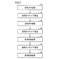
- FIG. 7 An example of a flowchart of such a manufacturing method is shown in FIG. In the entire manufacturing method, the process of transporting the substrate by the substrate transport robot is repeated many times. In the example shown in FIG. 7, the steps of transporting the substrate by the substrate transport robot are indicated by R1 to R3.
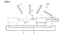
- FIG. 8 shows the general structure of each substrate transfer robot.
- the substrate transfer robot 100 includes a moving body 1 and a slider driving unit 2.
- the moving body 1 includes a placement unit 4 on which the substrate 3 is placed.
- the slider driving unit 2 includes a moving guide 5. Grease is used for the moving guide 5.
- the moving unit 1 can move in the direction of the arrow 91 along the moving guide 5.
- the oil mist 7 may be generated from the grease contained in the movement guide 5.
- the “display panel” is a concept including a liquid crystal display panel and including a display panel of a system other than liquid crystal.
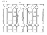
- An example of a cissing defect is shown in FIG.
- a repelling defect 12 occurs in a region where a plurality of pixel electrodes are arranged.
- a large number of substrate transfer robots are in operation at the display panel manufacturing site. Further, it is impossible to visually confirm where the oil mist is floating in the air or where the oil mist starts floating from the generation source. Under such circumstances, it has been difficult to identify the substrate transfer robot that is the source of oil mist at the display panel manufacturing site.
- an object of the present invention is to make it possible to easily identify the source of oil mist at the display panel manufacturing site.
- a display panel manufacturing method is a method of manufacturing a display panel using a substrate, and includes a step of performing at least one process on the substrate.
- n is an integer of 2 or more
- a k-th transport step of transporting the substrate by each k-th transport device having at least one grease adhering portion for each integer k from 1 to n is included.
- the grease adhering portion of the kth transport device includes a kth type identification material.
- the k-th type identification material has a characteristic that can be identified as being the k-th type in the group of the first to n-th type identification materials.
- the source of oil mist can be easily specified by the difference in the characteristics of the identification material.
- Embodiment 3 It is a conceptual diagram of the conveying apparatus group in Embodiment 3 based on this invention. It is a flowchart of the manufacturing method of the display panel based on a prior art. It is a conceptual diagram of the board
- a “display panel” may be a liquid crystal display panel or a display panel of another type.
- step S1 for cleaning the substrate is performed in this apparatus.
- step R1 is performed in which the substrate is transported by robot from the substrate cleaning apparatus to the solvent application apparatus.
- step S2 of applying a solvent to the substrate is performed in the solvent applying apparatus.
- step R2 is performed in which the substrate is transported by robot from the solvent coating device to the substrate inspection device.
- step S3 for inspecting the substrate is performed.
- step S3 a step R3 of carrying the substrate by robot from the substrate inspection apparatus to the substrate drying apparatus is performed.
- step S4 for drying the substrate is performed in the substrate drying apparatus.
- the robots used in the processes R1 to R3, that is, the substrate transfer robots, are different from each other.
- Each robot has a grease adhesion portion.
- grease containing a blue fluorescent dye is used for the grease adhering portion of the substrate transfer robot used in step R ⁇ b> 1.
- Grease containing a red fluorescent dye is used for the grease adhering portion of the substrate transport robot used in step R2.
- Grease containing a yellow fluorescent dye is used for the grease adhering portion of the substrate transfer robot used in step R3.
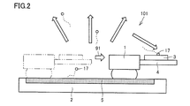
- FIG. 2 shows an example of a robot, that is, a substrate transfer robot.
- the substrate transfer robot 101 includes a moving body 1 and a slider driving unit 2.
- the moving body 1 includes a placement unit 4 on which the substrate 3 is placed.
- the slider driving unit 2 includes a moving guide 5. Grease is used for the moving guide 5.
- the moving unit 1 can move in the direction of the arrow 91 along the moving guide 5.
- the substrate transfer robot 101 in this embodiment is similar to the substrate transfer robot 100 shown in FIG. 8, but differs in that a fluorescent dye is included in the grease.
- the oil mist 17 may be generated from the grease included in the moving guide 5. If the oil mist 17 adheres to the substrate 3, a repellency defect 12 is generated. However, since the oil mist 17 contains a fluorescent dye, it can be identified using this.
- ultraviolet light may be applied to the repellency defect 12 as shown in FIG.
- the ultraviolet light 13 is irradiated from the UV light source 10 toward the repellency defect 12 of the substrate 3 in the dark room 14.
- the repellency defect 12 emits fluorescent light when irradiated with the ultraviolet light 13, it is determined from which substrate transfer robot the oil mist 17 causing the repellency defect 12 is generated. Can be easily identified.
- the source of oil mist can be easily identified.
- This oil mist generation source specifying method is a method of specifying a transport device that is a source of oil mist that adheres to a product, out of a plurality of transport devices each including a grease adhering portion including grease. Adding a material for identification having a characteristic capable of identifying which one of the plurality of transport devices to each of the grease adhering portions of the transport device, and transporting the product by the plurality of transport devices And a step of analyzing the identification material contained in the oil mist adhering to the product to identify which of the plurality of conveying devices is added.
- the “transport device” here is, for example, a substrate transport robot.
- the “grease adhesion part” is, for example, a moving guide.
- the “identification material” is, for example, a fluorescent dye.
- the “specifying step” is, for example, a step of irradiating with ultraviolet light. If it is sufficient to identify the actual oil mist adhering to one of a plurality of substrate transfer robots, this type of oil mist generation source identification method should be used. Can do.
- This oil mist generation source specifying method is a method for specifying a location that is a generation source of oil mist that adheres to a product among one or more conveying devices including a grease adhering portion that contains grease. Adding an identifying material having a characteristic capable of identifying which one of the plurality of grease adhering portions to each of the plurality of grease adhering portions existing in the transport device of the table or more; and A step of conveying the product by a conveying device of a table or more, and a type of analyzing the identification material contained in oil mist adhering to the product and adding it to any of the plurality of grease adhering portions. Identifying the above.
- This display panel manufacturing method is a method of manufacturing a display panel using a substrate, and includes a step of performing at least one process on the substrate, and when n is an integer of 2 or more, For each integer k of n, a k-th transport step of transporting the substrate by a k-th transport device having at least one grease adhering portion is included.
- the grease adhering portion of the k-th transport device includes a k-th type identification material.
- the k-th type identification material has a characteristic that can be identified as being the k-th type in the group of the first to n-th type identification materials.
- FIG. 4 shows an example of a flowchart of the display panel manufacturing method.
- the process step is performed before the k-th transport step, but this is only an example, and the process step may be performed after the k-th transport step.
- a substantial processing step for a substrate in a certain processing apparatus and a transporting step by a transporting device are not always performed alternately.
- carrying by another carrying device may be performed without performing substantial processing on the substrate.
- another process may be performed after one process on the substrate without interposing the process of transport by the transport device.
- This manufacturing method only needs to include a step of performing at least one treatment on the substrate.
- this manufacturing method means that the first transport step, the second transport step, the third transport step,..., The (n-1) th transport step, and the nth transport step are included.
- Each transporting process transports a substrate by its own transporting device, and the grease adhering portion of each transporting device includes an identification material having distinguishable characteristics. For example, in the case where a fluorescent dye is used as the identification material, it is only necessary to include fluorescent dyes having fluorescent emission characteristics of different colors for each transport device.
- This manufacturing method includes a step of inspecting whether any of the first to n-th type identification materials is attached or not attached to the surface of the substrate after the n-th transport step. It is preferable. This is because the presence or absence of oil mist adhesion can be confirmed more smoothly if the inspection step is included.
- the identification material is a fluorescent dye, and the characteristic is the kind of luminescent color. This is because if fluorescent dyes having different emission colors are used, they can be easily identified.
- the identification material may be other than the fluorescent dye. Any material can be used as long as it can be identified by a known technique.
- the identification material may be grease having a different composition, and the characteristic may be a surface composition of the grease adhesion portion.
- the surface composition By analyzing the surface composition, it is possible to easily identify from which substrate transfer robot the oil mist 17 is generated. That is, the source of oil mist can be easily identified.
- the identification material may be an isotope, and the characteristic may be the atomic mass number. It is possible to easily identify which substrate transfer robot the oil mist 17 is generated by examining which isotopes are contained in the oil mist by using a known technique. it can. That is, the source of oil mist can be easily identified.
- Embodiment 2 With reference to FIG. 5, the manufacturing method of the display panel in Embodiment 2 based on this invention is demonstrated.
- the basic method of this manufacturing method is the same as that described in the first embodiment.
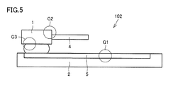
- one transport device includes a plurality of grease adhering portions.
- the substrate transfer robot 102 includes three grease adhering portions G1, G2, and G3.
- all of the n transport devices may each include a plurality of grease adhering units, and some of the n transport devices each include a plurality of grease adhering units. Also good.
- the k-th transport device includes a plurality of grease adhering portions including a grease adhering portion including the k-th type identification material, and is included in each of the plurality of grease adhering portions.
- the material has a characteristic capable of identifying which grease adhering portion of the k-th transport device.
- each transport device has a plurality of grease adhering portions, according to such a method, it is easy to identify which grease adhering portion of which transport device is the source of oil mist. Can do.
- This oil mist generation source specifying method is a method for specifying a location that is a generation source of oil mist that adheres to a product among one or more conveying devices including a grease adhering portion that contains grease. Adding an identifying material having a characteristic capable of identifying which one of the plurality of grease adhering portions to each of the plurality of grease adhering portions existing in the transport device of the table or more; and A step of conveying the product by a conveying device of a table or more, and a type of analyzing the identification material contained in oil mist adhering to the product and adding it to any of the plurality of grease adhering portions. Identifying the above.
- the transport device group 501 in the present embodiment is a transport device group including a plurality of transport devices for transporting a substrate when manufacturing a display panel, and each of the plurality of transport devices includes a grease adhering portion.
- the grease adhering portion includes an identification material having a characteristic that can be identified as to which conveyance device it belongs to.
- the transfer device group 501 shown in FIG. 6 includes substrate transfer robots 201 to 204 as transfer devices.
- the display panel manufacturing method can be performed, and when a repellency defect occurs, an oil mist causing the repellency defect is generated from any substrate transport robot. It is possible to easily identify whether it is a thing.
- This modification is a transport device for transporting a substrate when manufacturing a display panel, and includes a plurality of grease adhering portions.
- Each of the plurality of grease adhering portions includes an identification material having a characteristic capable of identifying which one of the grease adhering portions belongs. According to such a transport device group, it is possible to easily identify which grease adhering portion of which transport device is the generation source of oil mist.
- the present invention can be used in a method for manufacturing a display panel, a transport device and a transport device group used therefor, and an oil mist generation source specifying method.
Landscapes
- Physics & Mathematics (AREA)
- Nonlinear Science (AREA)
- Engineering & Computer Science (AREA)
- Manufacturing & Machinery (AREA)
- Chemical & Material Sciences (AREA)
- Crystallography & Structural Chemistry (AREA)
- General Physics & Mathematics (AREA)
- Optics & Photonics (AREA)
- Devices For Indicating Variable Information By Combining Individual Elements (AREA)
- Liquid Crystal (AREA)
Abstract
表示パネルの製造方法は、基板(3)を用いて表示パネルを製造する方法であって、基板(3)に対して少なくとも1つの処理を行なう工程を含み、さらに、nを2以上の整数としたとき1からnの各整数kについて、少なくとも1つのグリス付着部を有する第k搬送装置によって、基板(3)を搬送する第k搬送工程を含み、前記第k搬送装置の前記グリス付着部は、第k種類の識別用材料を含んでおり、前記第k種類の識別用材料は、第1種類から第n種類の識別用材料の群の中で第k種類であることが識別可能な特性を有する。
Description
本発明は、表示パネルの製造方法、これに用いられる搬送装置および搬送装置群ならびにオイルミスト発生源特定方法に関するものである。
従来、プラント内機器、車両などの部品からの油漏れを検知し、漏洩膜厚、漏洩面積および漏洩量を演算し、漏洩した油の油種および部位を特定することができる油検知装置が特開平10-311771号公報(特許文献1)に記載されている。
特許文献1に記載された油検知装置では、油漏れが現に発生していることが判明している対象物での検知作業しかすることができない。しかし、複数の装置が配置されて稼動しているプラント内において、ある1台の装置が油漏れを起こしている場合、漏れ出た油はその装置の表面に留まっているとは限らず、霧状の微粒子となって浮遊する場合がある。霧状の油の微粒子を以下「オイルミスト」という。オイルミストが空中を移動してきて他の装置または製品に付着した場合には、そのオイルミストがどの装置から発生したものであるかの特定は困難である。
ところで、一般的に、表示パネルの製造方法においては、基板に対して、洗浄工程、溶媒塗布工程、検査工程などの多くの工程が実施され、これらの工程間においては基板搬送ロボットが基板を搬送する。そのような製造方法のフローチャートの一例を図7に示す。製造方法の全体の中では、基板搬送ロボットによって基板を搬送する工程が何度も繰り返される。図7に示した例では、基板搬送ロボットによって基板を搬送する工程はR1~R3で示されている。
各基板搬送ロボットのおおまかな構造を図8に示す。基板搬送ロボット100は、移動体1とスライダ駆動部2とを備える。移動体1は基板3を載せるための載置部4を備える。スライダ駆動部2は移動用ガイド5を備える。移動用ガイド5にはグリスが用いられている。移動部1は移動用ガイド5に沿って矢印91の向きに移動することができる。このような基板搬送ロボット100を使用していると、移動用ガイド5に含まれるグリスからオイルミスト7が発生する場合がある。オイルミスト7が基板3に付着すると、のちに微小輝点となるいわゆるハジキ欠陥を発生させてしまう。なお、ここで「表示パネル」とは、液晶表示パネルを含み、液晶以外の方式の表示パネルも含む概念である。ハジキ欠陥の一例を図9に示す。複数の画素電極が配列されている領域の中に、ハジキ欠陥12が生じている。
表示パネルの製造現場においては、多くの台数の基板搬送ロボットが稼動している。また、オイルミストが空中を浮遊しているところや発生源から浮遊を開始するところは目視で確認することが不可能である。このような事情により、表示パネルの製造現場において、オイルミストの発生源となっている基板搬送ロボットを特定することは、従来は困難であった。
そこで、本発明は、表示パネルの製造現場において、オイルミストの発生源を容易に特定することができるようにすることを目的とする。
上記目的を達成するため、本発明に基づく表示パネルの製造方法は、基板を用いて表示パネルを製造する方法であって、前記基板に対して少なくとも1つの処理を行なう工程を含む。さらに、nを2以上の整数としたとき1からnの各整数kについて、少なくとも1つのグリス付着部を有する第k搬送装置によって、前記基板を搬送する第k搬送工程を含む。前記第k搬送装置の前記グリス付着部は、第k種類の識別用材料を含む。前記第k種類の識別用材料は、第1種類から第n種類の識別用材料の群の中で第k種類であることが識別可能な特性を有する。
本発明によれば、識別用材料の特性の違いによって、オイルミストの発生源を容易に特定することができる。
以下の説明において「表示パネル」といった場合、液晶表示パネルであってもよく、他の方式の表示パネルであってもよい。
(実施の形態1)
図1~図2を参照して、本発明に基づく実施の形態1における表示パネルの製造方法について説明する。この製造方法のフローチャートを図1に示す。まず、基板洗浄装置に基板が搬入され、この装置において基板を洗浄する工程S1が行なわれる。工程S1の後に、基板洗浄装置から溶媒塗布装置へと基板をロボットで搬送する工程R1が行なわれる。その後、溶媒塗布装置において、基板に溶媒を塗布する工程S2が行なわれる。工程S2の後に、溶媒塗布装置から基板検査装置へと基板をロボットで搬送する工程R2が行なわれる。その後、基板検査装置において、基板を検査する工程S3が行なわれる。工程S3の後に、基板検査装置から基板乾燥装置へと基板をロボットで搬送する工程R3が行なわれる。その後、基板乾燥装置において、基板を乾燥させる工程S4が行なわれる。工程R1~R3で使用されるロボットすなわち基板搬送ロボットはそれぞれ別々のものである。各ロボットにはそれぞれグリス付着部が存在する。図1に示されるように、工程R1で使用される基板搬送ロボットのグリス付着部には、青色の蛍光染料を含んだグリスが用いられている。工程R2で使用される基板搬送ロボットのグリス付着部には、赤色の蛍光染料を含んだグリスが用いられている。工程R3で使用される基板搬送ロボットのグリス付着部には、黄色の蛍光染料を含んだグリスが用いられている。
図1~図2を参照して、本発明に基づく実施の形態1における表示パネルの製造方法について説明する。この製造方法のフローチャートを図1に示す。まず、基板洗浄装置に基板が搬入され、この装置において基板を洗浄する工程S1が行なわれる。工程S1の後に、基板洗浄装置から溶媒塗布装置へと基板をロボットで搬送する工程R1が行なわれる。その後、溶媒塗布装置において、基板に溶媒を塗布する工程S2が行なわれる。工程S2の後に、溶媒塗布装置から基板検査装置へと基板をロボットで搬送する工程R2が行なわれる。その後、基板検査装置において、基板を検査する工程S3が行なわれる。工程S3の後に、基板検査装置から基板乾燥装置へと基板をロボットで搬送する工程R3が行なわれる。その後、基板乾燥装置において、基板を乾燥させる工程S4が行なわれる。工程R1~R3で使用されるロボットすなわち基板搬送ロボットはそれぞれ別々のものである。各ロボットにはそれぞれグリス付着部が存在する。図1に示されるように、工程R1で使用される基板搬送ロボットのグリス付着部には、青色の蛍光染料を含んだグリスが用いられている。工程R2で使用される基板搬送ロボットのグリス付着部には、赤色の蛍光染料を含んだグリスが用いられている。工程R3で使用される基板搬送ロボットのグリス付着部には、黄色の蛍光染料を含んだグリスが用いられている。
ロボットすなわち基板搬送ロボットの一例について図2に示す。基板搬送ロボット101は、移動体1とスライダ駆動部2とを備える。移動体1は基板3を載せるための載置部4を備える。スライダ駆動部2は移動用ガイド5を備える。移動用ガイド5にはグリスが用いられている。移動部1は移動用ガイド5に沿って矢印91の向きに移動することができる。本実施の形態における基板搬送ロボット101は、図8に示した基板搬送ロボット100と似ているが、グリスに蛍光染料が含まれているという点で異なる。
このような基板搬送ロボット101を使用していると、移動用ガイド5に含まれるグリスからオイルミスト17が発生する場合がある。オイルミスト17が基板3に付着すると、ハジキ欠陥12を発生させてしまうが、オイルミスト17には蛍光染料が含まれているのでこれを利用して識別が可能である。
本実施の形態では、オイルミストの発生源を特定するためには、図3に示すように、ハジキ欠陥12に紫外光を当てればよい。図3に示した例では、暗室14内において基板3のハジキ欠陥12に向けてUV光源10から紫外光13を照射している。紫外光13を照射されたときにハジキ欠陥12が何色に蛍光発光するかを視認することによって、このハジキ欠陥12を引き起こしたオイルミスト17がいずれの基板搬送ロボットから発生したものであるかを容易に特定することができる。
以上のようにして、本発明によれば、オイルミストの発生源を容易に特定することができる。
本実施の形態で説明した表示パネルの製造方法を、「オイルミスト発生源特定方法」として把握することもできる。このオイルミスト発生源特定方法は、グリスを含むグリス付着部をそれぞれ備える複数の搬送装置のうち、製品に付着するオイルミストの発生源となっている搬送装置を特定する方法であって、前記複数の搬送装置のグリス付着部の各々に、前記複数の搬送装置のうちのいずれであるかを識別可能な特性を有する識別用材料を添加する工程と、前記複数の搬送装置によって前記製品を搬送する工程と、前記製品に付着したオイルミストに含まれる前記識別用材料を分析して前記複数の搬送装置のうちのいずれに添加した種類のものであるかを特定する工程とを含む。ここでいう「搬送装置」は、たとえば基板搬送ロボットのことである。「グリス付着部」とは、たとえば移動用ガイドのことである。「識別用材料」とは、たとえば蛍光染料のことである。「特定する工程」とは、たとえば紫外光を照射する工程のことである。現実に付着しているオイルミストが、複数ある基板搬送ロボットのうちどの1台から発生したものであるかが特定されれば足りる場合には、このようなオイルミスト発生源特定方法によって対処することができる。
1台のみまたは複数台ある基板搬送ロボットには複数のグリス付着部があるのが普通であるが、これらの複数のグリス付着部のいずれがオイルミストの発生源になっているかを特定したい場合は、次のようなオイルミスト発生源特定方法によって対処することができる。
このオイルミスト発生源特定方法は、グリスを含むグリス付着部を備える1台以上の搬送装置のうち、製品に付着するオイルミストの発生源となっている箇所を特定する方法であって、前記1台以上の搬送装置の中に存在する複数のグリス付着部の各々に、前記複数のグリス付着部のうちのいずれであるかを識別可能な特性を有する識別用材料を添加する工程と、前記1台以上の搬送装置によって前記製品を搬送する工程と、前記製品に付着したオイルミストに含まれる前記識別用材料を分析して前記複数のグリス付着部のうちのいずれに添加した種類のものであるかを特定する工程とを含む。
本実施の形態における表示パネルの製造方法は、以下のように把握することができる。
この表示パネルの製造方法は、基板を用いて表示パネルを製造する方法であって、前記基板に対して少なくとも1つの処理を行なう工程を含み、さらに、nを2以上の整数としたとき1からnの各整数kについて、少なくとも1つのグリス付着部を有する第k搬送装置によって、前記基板を搬送する第k搬送工程を含む。前記第k搬送装置の前記グリス付着部は、第k種類の識別用材料を含んでいる。前記第k種類の識別用材料は、第1種類から第n種類の識別用材料の群の中で第k種類であることが識別可能な特性を有する。
この表示パネルの製造方法は、基板を用いて表示パネルを製造する方法であって、前記基板に対して少なくとも1つの処理を行なう工程を含み、さらに、nを2以上の整数としたとき1からnの各整数kについて、少なくとも1つのグリス付着部を有する第k搬送装置によって、前記基板を搬送する第k搬送工程を含む。前記第k搬送装置の前記グリス付着部は、第k種類の識別用材料を含んでいる。前記第k種類の識別用材料は、第1種類から第n種類の識別用材料の群の中で第k種類であることが識別可能な特性を有する。
この表示パネルの製造方法のフローチャートの一例を図4に示す。図4に示した例では処理を行なう工程が第k搬送工程より前で行なわれているが、これは一例に過ぎず、処理を行なう工程が第k搬送工程より後で行なわれてもよい。
この製造方法では、図1に示したように何らかの処理装置における基板に対する実質的な処理の工程と搬送装置による搬送の工程とが交互に行なわれるとは限らない。ある搬送装置による搬送の後に、基板に対する実質的な処理を行なうことなく、他の搬送装置による搬送が行なわれてもよい。また、搬送装置による搬送の工程を挟むことなく、基板に対するひとつの処理の後に続けて他の処理が行なわれてもよい。この製造方法としては、基板に対して少なくとも1つの処理を行なう工程を含んでいればよい。
「nを2以上の整数としたとき1からnの各整数kについて、少なくとも1つのグリス付着部を有する第k搬送装置によって、前記基板を搬送する第k搬送工程を含む」とは、たとえば、整数nを適当に定めたとき、この製造方法は、第1搬送工程、第2搬送工程、第3搬送工程、…、第n-1搬送工程、第n搬送工程を含むという意味である。各搬送工程は、それぞれ独自の搬送装置によって基板を搬送するものであり、各搬送装置のグリス付着部は、それぞれ識別可能な特性を有する識別用材料を含んでいる。たとえば、識別用材料として蛍光染料を用いる場合であれば、各搬送装置ごとに異なった色の蛍光発光特性を有する蛍光染料が含まれていればよい。
このような製造方法であれば、ハジキ欠陥12を引き起こしたオイルミスト17に含まれている識別用材料を確認することによって、オイルミスト17がいずれの基板搬送ロボットから発生したものであるかを容易に特定することができる。すなわち、オイルミストの発生源を容易に特定することができる。
この製造方法においては、第n搬送工程より後に、前記基板の表面に第1種類から第n種類の識別用材料のいずれが付着しているかあるいはいずれも付着していないかを検査する工程を含むことが好ましい。このように検査する工程が含まれていれば、より円滑にオイルミストの付着の有無を確認できるからである。
この製造方法においては、識別用材料は蛍光染料であり、前記特性は発光色の種類であることが好ましい。このように発光色がそれぞれ異なる蛍光染料を用いれば、容易に識別可能だからである。
ここまで、蛍光染料を使用する例を中心に説明してきたが、識別用材料は蛍光染料以外であってもよい。公知技術によって種類の識別ができるような材料であればよい。
蛍光染料以外の例としては、識別用材料は組成を異ならせたグリスであり、前記特性は前記グリス付着部の表面組成であってもよい。表面組成を分析することにより、オイルミスト17がいずれの基板搬送ロボットから発生したものであるかを容易に特定することができる。すなわち、オイルミストの発生源を容易に特定することができる。
さらに他の例としては、識別用材料は同位体であり、前記特性は原子の質量数であってもよい。オイルミストに含まれているものが同位体のいずれであるかを、公知技術を用いて調べることにより、オイルミスト17がいずれの基板搬送ロボットから発生したものであるかを容易に特定することができる。すなわち、オイルミストの発生源を容易に特定することができる。
(実施の形態2)
図5を参照して、本発明に基づく実施の形態2における表示パネルの製造方法について説明する。この製造方法は、基本的な部分は実施の形態1で説明したものと共通するが、図5に示すように、1台の搬送装置が複数のグリス付着部を備えている。図5に示した例では、基板搬送ロボット102は3つのグリス付着部G1,G2,G3を備えている。
図5を参照して、本発明に基づく実施の形態2における表示パネルの製造方法について説明する。この製造方法は、基本的な部分は実施の形態1で説明したものと共通するが、図5に示すように、1台の搬送装置が複数のグリス付着部を備えている。図5に示した例では、基板搬送ロボット102は3つのグリス付着部G1,G2,G3を備えている。
本実施の形態では、n台の搬送装置の全てがそれぞれ複数のグリス付着部を備えていてもよく、n台の搬送装置のうち一部の搬送装置がそれぞれ複数のグリス付着部を備えていてもよい。
本実施の形態では、前記第k搬送装置は、前記第k種類の識別用材料を含むグリス付着部を含めて複数のグリス付着部を備えており、前記複数のグリス付着部の各々に含まれる材料は、前記第k搬送装置のうちいずれのグリス付着部であるかを識別可能な特性を有する。
各搬送装置が複数のグリス付着部を備えている場合にも、このような方法によれば、いずれの搬送装置のいずれのグリス付着部がオイルミストの発生源であるかを容易に特定することができる。
このオイルミスト発生源特定方法は、グリスを含むグリス付着部を備える1台以上の搬送装置のうち、製品に付着するオイルミストの発生源となっている箇所を特定する方法であって、前記1台以上の搬送装置の中に存在する複数のグリス付着部の各々に、前記複数のグリス付着部のうちのいずれであるかを識別可能な特性を有する識別用材料を添加する工程と、前記1台以上の搬送装置によって前記製品を搬送する工程と、前記製品に付着したオイルミストに含まれる前記識別用材料を分析して前記複数のグリス付着部のうちのいずれに添加した種類のものであるかを特定する工程とを含む。現実に付着しているオイルミストが、複数ある基板搬送ロボットのうちどの1台から発生したものであるかが特定されるだけでなく、その1台の中に複数あるグリス付着部のいずれから発生したものであるかまでを特定したい場合には、このようなオイルミスト発生源特定方法によって対処することができる。
(実施の形態3)
図6を参照して、本発明に基づく実施の形態3における搬送装置群について説明する。
図6を参照して、本発明に基づく実施の形態3における搬送装置群について説明する。
本実施の形態における搬送装置群501は、表示パネルを製造する際に基板を搬送するための複数の搬送装置を含む搬送装置群であり、前記複数の搬送装置の各々は、グリス付着部を備え、前記グリス付着部は、いずれの搬送装置に属するものであるか識別可能な特性を有する識別用材料を含んでいる。図6に示した搬送装置群501は、搬送装置として基板搬送ロボット201~204を含む。
本実施の形態における搬送装置群によれば、表示パネルの製造方法を実施することができ、なおかつ、ハジキ欠陥が生じた場合にそのハジキ欠陥を引き起こしたオイルミストがいずれの基板搬送ロボットから発生したものであるかを容易に特定することができる。
(変形例)
本実施の形態における搬送装置群の変形例として、単体の搬送装置について説明する。この変形例は、表示パネルを製造する際に基板を搬送するための搬送装置であり、複数のグリス付着部を備える。前記複数のグリス付着部の各々は、いずれのグリス付着部に属するものであるか識別可能な特性を有する識別用材料を含んでいる。このような搬送装置群によれば、いずれの搬送装置のいずれのグリス付着部がオイルミストの発生源であるかを容易に特定することができる。
本実施の形態における搬送装置群の変形例として、単体の搬送装置について説明する。この変形例は、表示パネルを製造する際に基板を搬送するための搬送装置であり、複数のグリス付着部を備える。前記複数のグリス付着部の各々は、いずれのグリス付着部に属するものであるか識別可能な特性を有する識別用材料を含んでいる。このような搬送装置群によれば、いずれの搬送装置のいずれのグリス付着部がオイルミストの発生源であるかを容易に特定することができる。
なお、今回開示した上記実施の形態はすべての点で例示であって制限的なものではない。本発明の範囲は上記した説明ではなくて請求の範囲によって示され、請求の範囲と均等の意味および範囲内でのすべての変更を含むものである。
本発明は、表示パネルの製造方法、これに用いられる搬送装置および搬送装置群ならびにオイルミスト発生源特定方法に利用することができる。
1 移動体、2 スライダ駆動部、3 基板、4 載置部、5 移動用ガイド、7,17 オイルミスト、10 UV光源、12 ハジキ欠陥、13 紫外光、14 暗室、100,101,102,201,202,203,204 基板搬送ロボット、501 搬送装置群。
Claims (10)
- 基板を用いて表示パネルを製造する方法であって、
前記基板に対して少なくとも1つの処理を行なう工程を含み、さらに、
nを2以上の整数としたとき1からnの各整数kについて、少なくとも1つのグリス付着部を有する第k搬送装置によって、前記基板を搬送する第k搬送工程を含み、
前記第k搬送装置の前記グリス付着部は、第k種類の識別用材料を含んでおり、前記第k種類の識別用材料は、第1種類から第n種類の識別用材料の群の中で第k種類であることが識別可能な特性を有する、表示パネルの製造方法。 - 第n搬送工程より後に、
前記基板の表面に第1種類から第n種類の識別用材料のいずれが付着しているかあるいはいずれも付着していないかを検査する工程を含む、請求項1に記載の表示パネルの製造方法。 - 前記識別用材料は蛍光染料であり、前記特性は発光色の種類である、請求項1または2に記載の表示パネルの製造方法。
- 前記識別用材料は組成を異ならせたグリスであり、前記特性は前記グリス付着部の表面組成である、請求項1または2に記載の表示パネルの製造方法。
- 前記識別用材料は同位体であり、前記特性は原子の質量数である、請求項1または2に記載の表示パネルの製造方法。
- 前記第k搬送装置は、前記第k種類の識別用材料を含むグリス付着部を含めて複数のグリス付着部を備えており、前記複数のグリス付着部の各々に含まれる材料は、前記第k搬送装置のうちいずれのグリス付着部であるかを識別可能な特性を有する、請求項1から5のいずれかに記載の表示パネルの製造方法。
- 表示パネルを製造する際に基板を搬送するための複数の搬送装置を含む搬送装置群であり、
前記複数の搬送装置の各々は、グリス付着部を備え、
前記グリス付着部は、いずれの搬送装置に属するものであるか識別可能な特性を有する識別用材料を含んでいる、搬送装置群。 - 表示パネルを製造する際に基板を搬送するための搬送装置であり、
複数のグリス付着部を備え、前記複数のグリス付着部の各々は、いずれのグリス付着部に属するものであるか識別可能な特性を有する識別用材料を含んでいる、搬送装置。 - グリスを含むグリス付着部をそれぞれ備える複数の搬送装置のうち、製品に付着するオイルミストの発生源となっている搬送装置を特定する方法であって、
前記複数の搬送装置のグリス付着部の各々に、前記複数の搬送装置のうちのいずれであるかを識別可能な特性を有する識別用材料を添加する工程と、
前記複数の搬送装置によって前記製品を搬送する工程と、
前記製品に付着したオイルミストに含まれる前記識別用材料を分析して前記複数の搬送装置のうちのいずれに添加した種類のものであるかを特定する工程とを含む、オイルミスト発生源特定方法。 - グリスを含むグリス付着部を備える1台以上の搬送装置のうち、製品に付着するオイルミストの発生源となっている箇所を特定する方法であって、
前記1台以上の搬送装置の中に存在する複数のグリス付着部の各々に、前記複数のグリス付着部のうちのいずれであるかを識別可能な特性を有する識別用材料を添加する工程と、
前記1台以上の搬送装置によって前記製品を搬送する工程と、
前記製品に付着したオイルミストに含まれる前記識別用材料を分析して前記複数のグリス付着部のうちのいずれに添加した種類のものであるかを特定する工程とを含む、オイルミスト発生源特定方法。
Applications Claiming Priority (2)
| Application Number | Priority Date | Filing Date | Title |
|---|---|---|---|
| JP2011-279559 | 2011-12-21 | ||
| JP2011279559 | 2011-12-21 |
Publications (1)
| Publication Number | Publication Date |
|---|---|
| WO2013094632A1 true WO2013094632A1 (ja) | 2013-06-27 |
Family
ID=48668516
Family Applications (1)
| Application Number | Title | Priority Date | Filing Date |
|---|---|---|---|
| PCT/JP2012/082898 Ceased WO2013094632A1 (ja) | 2011-12-21 | 2012-12-19 | 表示パネルの製造方法、これに用いられる搬送装置および搬送装置群ならびにオイルミスト発生源特定方法 |
Country Status (1)
| Country | Link |
|---|---|
| WO (1) | WO2013094632A1 (ja) |
Citations (6)
| Publication number | Priority date | Publication date | Assignee | Title |
|---|---|---|---|---|
| JPH10311771A (ja) * | 1997-05-12 | 1998-11-24 | Toshiba Corp | 油検知装置 |
| JP2000068175A (ja) * | 1998-08-24 | 2000-03-03 | Advanced Display Inc | 発塵検出方法と、液晶表示装置または半導体装置の製造方法 |
| JP2001250802A (ja) * | 2001-01-11 | 2001-09-14 | Yokogawa Electric Corp | 製造プロセスの異物除去システム。 |
| JP2006349917A (ja) * | 2005-06-15 | 2006-12-28 | Nec Lcd Technologies Ltd | 液晶表示パネルの製造装置及びその製造方法 |
| JP2008260072A (ja) * | 2007-04-10 | 2008-10-30 | Toyota Industries Corp | 不良原因特定方法及び基板処理装置 |
| JP2009204607A (ja) * | 2008-01-28 | 2009-09-10 | Nitto Denko Corp | 光学表示ユニットの検査方法および検査装置 |
-
2012
- 2012-12-19 WO PCT/JP2012/082898 patent/WO2013094632A1/ja not_active Ceased
Patent Citations (6)
| Publication number | Priority date | Publication date | Assignee | Title |
|---|---|---|---|---|
| JPH10311771A (ja) * | 1997-05-12 | 1998-11-24 | Toshiba Corp | 油検知装置 |
| JP2000068175A (ja) * | 1998-08-24 | 2000-03-03 | Advanced Display Inc | 発塵検出方法と、液晶表示装置または半導体装置の製造方法 |
| JP2001250802A (ja) * | 2001-01-11 | 2001-09-14 | Yokogawa Electric Corp | 製造プロセスの異物除去システム。 |
| JP2006349917A (ja) * | 2005-06-15 | 2006-12-28 | Nec Lcd Technologies Ltd | 液晶表示パネルの製造装置及びその製造方法 |
| JP2008260072A (ja) * | 2007-04-10 | 2008-10-30 | Toyota Industries Corp | 不良原因特定方法及び基板処理装置 |
| JP2009204607A (ja) * | 2008-01-28 | 2009-09-10 | Nitto Denko Corp | 光学表示ユニットの検査方法および検査装置 |
Similar Documents
| Publication | Publication Date | Title |
|---|---|---|
| JP5272909B2 (ja) | 検査装置 | |
| US8711348B2 (en) | Method of inspecting wafer | |
| DE69510023D1 (de) | Gerät und Verfahren zum Reinigen von Fotomasken | |
| US7902524B2 (en) | Portable corrosion detection apparatus | |
| JP2006229184A5 (ja) | ||
| TW200732652A (en) | Oblique transmission illumination inspection system and method for inspecting a glass sheet | |
| KR20140075171A (ko) | 패널 검사장치 | |
| ATE511991T1 (de) | Verfahren zum separieren von wenigstens zwei brücken eines segmentierten transportsystems für bedruckstoffe | |
| TW363163B (en) | Decision method for moving sequence and alignment apparatus for applying the method | |
| TW200714894A (en) | Mask defect inspecting method, mask defect inspecting apparatus, and semiconductor device manufacturing method | |
| WO2013094632A1 (ja) | 表示パネルの製造方法、これに用いられる搬送装置および搬送装置群ならびにオイルミスト発生源特定方法 | |
| WO2015129531A1 (ja) | 検査装置、検査方法、プログラムおよび記録媒体 | |
| JPS6373140A (ja) | ガラス部品表面汚れ部位測定法 | |
| US20150022652A1 (en) | Device and method for inspecting a sealing member | |
| JP2011224512A (ja) | 搬送ローラ自動洗浄装置 | |
| Terasaki et al. | Mechanoluminescence visual inspection of microcrack generation through fatigue process in flexible electronic films | |
| JP6425970B2 (ja) | 検査装置および検査方法 | |
| CN104345023A (zh) | 污染物测量基底、设备及使用该设备制造基底的方法 | |
| JP7245703B2 (ja) | Pcbを含む油の検出方法、及びpcbを含む油の除去方法 | |
| JP2013222728A (ja) | インプリントシステム | |
| US20140127837A1 (en) | Thin film deposition apparatus and method of depositing thin film using the same | |
| JP5973846B2 (ja) | 撥液性樹脂の改質パターン検査方法および装置 | |
| JP2012141235A (ja) | 検査装置、検査方法および検査プログラム | |
| JP2006228862A (ja) | 異物除去装置,処理システム及び異物除去方法 | |
| US9435748B2 (en) | Detection of contaminated areas |
Legal Events
| Date | Code | Title | Description |
|---|---|---|---|
| 121 | Ep: the epo has been informed by wipo that ep was designated in this application |
Ref document number: 12859135 Country of ref document: EP Kind code of ref document: A1 |
|
| NENP | Non-entry into the national phase |
Ref country code: DE |
|
| 122 | Ep: pct application non-entry in european phase |
Ref document number: 12859135 Country of ref document: EP Kind code of ref document: A1 |
|
| NENP | Non-entry into the national phase |
Ref country code: JP |