WO2013088808A1 - カバーガラス板の製造方法 - Google Patents
カバーガラス板の製造方法 Download PDFInfo
- Publication number
- WO2013088808A1 WO2013088808A1 PCT/JP2012/074171 JP2012074171W WO2013088808A1 WO 2013088808 A1 WO2013088808 A1 WO 2013088808A1 JP 2012074171 W JP2012074171 W JP 2012074171W WO 2013088808 A1 WO2013088808 A1 WO 2013088808A1
- Authority
- WO
- WIPO (PCT)
- Prior art keywords
- glass plate
- cover glass
- upper mold
- shape
- mold
- Prior art date
Links
- 239000006059 cover glass Substances 0.000 title claims abstract description 127
- 238000004519 manufacturing process Methods 0.000 title claims abstract description 38
- 238000000034 method Methods 0.000 title claims abstract description 34
- 239000006060 molten glass Substances 0.000 claims abstract description 74
- 238000003825 pressing Methods 0.000 claims abstract description 52
- 238000005498 polishing Methods 0.000 claims description 60
- 238000012545 processing Methods 0.000 claims description 58
- 238000000227 grinding Methods 0.000 claims description 52
- 239000011521 glass Substances 0.000 claims description 20
- 230000001105 regulatory effect Effects 0.000 claims description 4
- 238000003754 machining Methods 0.000 abstract 2
- 238000000465 moulding Methods 0.000 description 52
- 238000012805 post-processing Methods 0.000 description 13
- 230000002093 peripheral effect Effects 0.000 description 12
- BASFCYQUMIYNBI-UHFFFAOYSA-N platinum Chemical compound [Pt] BASFCYQUMIYNBI-UHFFFAOYSA-N 0.000 description 10
- 238000002844 melting Methods 0.000 description 8
- 230000008018 melting Effects 0.000 description 8
- 239000005357 flat glass Substances 0.000 description 5
- 229910052697 platinum Inorganic materials 0.000 description 5
- 230000000694 effects Effects 0.000 description 4
- 239000007788 liquid Substances 0.000 description 4
- 239000012528 membrane Substances 0.000 description 4
- 238000000926 separation method Methods 0.000 description 4
- 239000004575 stone Substances 0.000 description 4
- 238000005520 cutting process Methods 0.000 description 2
- 230000006866 deterioration Effects 0.000 description 2
- 238000009826 distribution Methods 0.000 description 2
- 238000007711 solidification Methods 0.000 description 2
- 230000008023 solidification Effects 0.000 description 2
- 239000011248 coating agent Substances 0.000 description 1
- 238000000576 coating method Methods 0.000 description 1
- 229910052751 metal Inorganic materials 0.000 description 1
- 239000002184 metal Substances 0.000 description 1
- 230000002265 prevention Effects 0.000 description 1
- 239000011347 resin Substances 0.000 description 1
- 229920005989 resin Polymers 0.000 description 1
Images


Classifications
-
- C—CHEMISTRY; METALLURGY
- C03—GLASS; MINERAL OR SLAG WOOL
- C03B—MANUFACTURE, SHAPING, OR SUPPLEMENTARY PROCESSES
- C03B11/00—Pressing molten glass or performed glass reheated to equivalent low viscosity without blowing
- C03B11/06—Construction of plunger or mould
- C03B11/08—Construction of plunger or mould for making solid articles, e.g. lenses
- C03B11/082—Construction of plunger or mould for making solid articles, e.g. lenses having profiled, patterned or microstructured surfaces
-
- B—PERFORMING OPERATIONS; TRANSPORTING
- B24—GRINDING; POLISHING
- B24B—MACHINES, DEVICES, OR PROCESSES FOR GRINDING OR POLISHING; DRESSING OR CONDITIONING OF ABRADING SURFACES; FEEDING OF GRINDING, POLISHING, OR LAPPING AGENTS
- B24B13/00—Machines or devices designed for grinding or polishing optical surfaces on lenses or surfaces of similar shape on other work; Accessories therefor
- B24B13/015—Machines or devices designed for grinding or polishing optical surfaces on lenses or surfaces of similar shape on other work; Accessories therefor of television picture tube viewing panels, headlight reflectors or the like
-
- B—PERFORMING OPERATIONS; TRANSPORTING
- B24—GRINDING; POLISHING
- B24B—MACHINES, DEVICES, OR PROCESSES FOR GRINDING OR POLISHING; DRESSING OR CONDITIONING OF ABRADING SURFACES; FEEDING OF GRINDING, POLISHING, OR LAPPING AGENTS
- B24B9/00—Machines or devices designed for grinding edges or bevels on work or for removing burrs; Accessories therefor
- B24B9/02—Machines or devices designed for grinding edges or bevels on work or for removing burrs; Accessories therefor characterised by a special design with respect to properties of materials specific to articles to be ground
- B24B9/06—Machines or devices designed for grinding edges or bevels on work or for removing burrs; Accessories therefor characterised by a special design with respect to properties of materials specific to articles to be ground of non-metallic inorganic material, e.g. stone, ceramics, porcelain
- B24B9/08—Machines or devices designed for grinding edges or bevels on work or for removing burrs; Accessories therefor characterised by a special design with respect to properties of materials specific to articles to be ground of non-metallic inorganic material, e.g. stone, ceramics, porcelain of glass
- B24B9/10—Machines or devices designed for grinding edges or bevels on work or for removing burrs; Accessories therefor characterised by a special design with respect to properties of materials specific to articles to be ground of non-metallic inorganic material, e.g. stone, ceramics, porcelain of glass of plate glass
-
- C—CHEMISTRY; METALLURGY
- C03—GLASS; MINERAL OR SLAG WOOL
- C03B—MANUFACTURE, SHAPING, OR SUPPLEMENTARY PROCESSES
- C03B2215/00—Press-moulding glass
- C03B2215/40—Product characteristics
- C03B2215/41—Profiled surfaces
Definitions
- the present invention relates to a method for manufacturing a cover glass plate, for example, a method for manufacturing a cover glass plate provided on an image display surface of a smartphone.
- a digital device having an image display function (for example, a mobile phone, a smartphone, a mobile computer, etc.) is usually provided with a cover glass plate for protecting the image display surface.
- the cover glass plate is manufactured by cutting a large area plate glass formed into a flat plate shape into a predetermined size. For this reason, the outer frame processing is required after cutting the plate glass. That is, it is necessary to perform outline frame processing that smoothly chamfers or rounds the boundaries of the side surfaces that form four corners and four sides of a rectangular plate glass (see, for example, Patent Document 1).
- post-processing is required to make the surface of the plate glass formed into a flat plate into a curved surface.
- the present invention has been made in view of such a situation, and the object thereof is to form an arbitrary outer frame shape and surface shape without performing the outer frame processing of the cover glass plate or the post-processing of the cover glass plate surface. It is providing the manufacturing method of a cover glass plate which makes it possible to manufacture the cover glass plate which has easily.
- the method for producing a cover glass plate of the present invention includes a dropping step of dropping molten glass onto a lower mold, and pressing the molten glass on the lower mold with an upper mold having a recess.
- the molten glass is filled in the concave portion of the upper mold, and further protruded from the concave portion between the upper mold and the lower mold, and the concave shape of the upper mold is transferred.
- a pressing step for forming a preformed body comprising: a molded body having one surface; and a protruding portion having a second surface to which a lower mold shape is transferred, which is a portion other than the molded body, and the protruding portion And a processing step of removing all from the preform.
- the upper surface and the side surface of the cover glass plate are formed by the concave portion of the upper mold, and in the processing step, the lower surface of the cover glass plate is formed by surface grinding or surface polishing the second surface. Is preferred.
- the lower mold has a concave portion, and the concave portion and the convex portion are formed on the second surface of the protruding portion.
- the convex portion is provided on the outermost periphery of the second surface.
- the area of the convex portion occupying the second surface is 1/4 or more of the entire second surface.
- the second surface is provided with the rectangular concave portion and the convex portion over the entire outermost periphery of the second surface so as to surround the periphery of the concave portion.
- the shape of the concave portion on the second surface is preferably a circular shape, a square shape, a honeycomb shape, or a mesh shape.
- the area of the convex portion occupying the second surface is 1 ⁇ 2 or less of the area of the concave portion occupying the second surface.
- the side surface of the concave portion of the second surface has a draft taper shape of 3 ° or more with respect to the normal line of the bottom surface of the concave portion.
- a part or the whole surface shape of the concave portion of the upper mold is a curved surface
- a part or the whole surface shape of the first surface is a curved surface
- the surface of the upper mold that comes into contact with the protruding portion is preferably rougher than the surface of the concave portion of the upper mold.
- an outer mold is disposed between the upper mold and the lower mold, and the expansion of the protruding portion is regulated by the outer mold.
- the outer frame shape of the cover glass plate is determined by the concave portion of the upper mold, it is not necessary to process the outer frame of the cover glass plate if all the protruding portions are removed from the preform by surface grinding or surface polishing in the processing step. .
- the surface shape of the cover glass plate is determined by the concave portion of the upper mold, it is not necessary to perform post-processing on the surface of the cover glass plate. Therefore, according to the present invention, it is possible to easily manufacture a cover glass plate having an arbitrary outer frame shape and surface shape without performing the outer frame processing of the cover glass plate or the post-processing of the cover glass plate surface. is there.
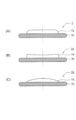
- FIG. 1st Embodiment of the manufacturing method of a cover glass plate is shown.
- This manufacturing method is shown in the molding step shown in the cross-sectional views of FIGS. 1A to 1C, the plan view of FIGS. 1D and 1E, and the cross-sectional views of FIGS. 1F and 1G.
- a processing step In the forming step including the dropping step (A), the moving step (B), and the pressing step (C), the preform (sheet glass blank) 7 is formed by the direct pressing method, and the processing steps (D) to (G) Then, the cover glass plate 8 as a finished product is formed.
- the cover glass plate 8 is used, for example, to cover an image display surface of a digital device (for example, a mobile phone, a smartphone, a mobile computer, etc.) having an image display function.
- a digital device for example, a mobile phone, a smartphone, a mobile computer, etc.
- a fixed amount of molten glass 3 is dropped onto the flat portion 1 f of the lower mold 1 in the dropping step (A). That is, the molten glass 3 obtained by melting in the melting furnace is poured out from the platinum nozzle 6 and cut by the blade 5, whereby a certain amount of the molten glass 3 is dropped onto the flat portion 1 f of the lower mold 1.
- the lower mold 1 is heated by the heater 4. Therefore, the molten glass 3 on the flat portion 1f is held and controlled in a state where a predetermined viscosity is maintained.
- the lower mold 1 is moved to a predetermined position below the upper mold 2.
- the upper mold 2 is heated by the heater 4 so that the molten glass 3 is not rapidly cooled by the upper mold 2. Therefore, the molten glass 3 on the flat portion 1 f is held and controlled in a state where a predetermined viscosity is maintained even when it contacts the upper mold 2.
- the process proceeds to the pressing process (C).
- the pressing step (C) the upper mold 2 is lowered, and the molten glass 3 on the flat portion 1 f of the lower mold 1 is pressed by the upper mold 2, so that the molten glass 3 is formed into the upper mold 2.
- the pre-molded body 7 having the protruding portion 7b is formed by filling the concave portion 2a and protruding from the concave portion 2a between the upper mold 2 and the lower mold 1. In this way, the molding surface can be transferred to the preform 7 up to the outermost periphery of the outer surface Sb (FIG. 1B) of the upper mold 2 by protruding and molding.
- the preformed body 7 includes a molded body main body 7a and a protruding portion 7b (shaded portion).
- the protruding portion 7b which is an unnecessary portion, is completely removed from the preform 7 (that is, until the outer peripheral surface of the molded body 7a is reached). Only the molded body 7a remains. That is, as shown in FIGS. 1E and 1G, a cover glass plate 8 as a finished product is formed.
- the outer frame shape of the cover glass plate 8 is determined by the recess 2a of the upper mold 2, if the protruding portion 7b is completely removed from the preform 7 by surface grinding or surface polishing in the processing step, the outer frame of the cover glass plate 8 There is no need to perform processing (for example, four-frame outline processing corresponding to the rectangle of the image display surface). Further, since the surface shape of the cover glass plate 8 is determined by the recess 2a of the upper mold 2, there is no need to perform post-processing on the surface of the cover glass plate. Therefore, according to the configuration of this embodiment, the thin cover glass plate 8 having any outer frame shape and surface shape can be obtained without performing the outer frame processing of the cover glass plate 8 and the post-processing of the cover glass plate surface. It can be easily manufactured.
- the shape of the upper surface 8 a of the cover glass plate 8 is determined by the shape of the recess 2 a filled with the molten glass 3. Therefore, as shown in FIG. 1B, if the surface shape of a part (or the whole) of the recess 2a is a curved surface, the surface shape of a part (or the whole) of the upper surface 8a of the cover glass plate 8 is changed. Can be curved. Therefore, according to the configuration of this embodiment, it is possible to easily meet the needs for changing the specification of the surface of the cover glass plate 8 from a flat surface to a curved surface.
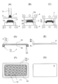
- FIG. 2 shows a specific example of the preform 7.
- FIG. 2A shows a preform 7 obtained by the molding process of FIG. That is, the preformed body 7 has a flat surface on the molded body main body 7a.
- FIG. 2 (B) shows a preformed body 7A in which the molded body main body 7a has a concave surface
- FIG. 2 (C) shows a preformed body 7B in which the molded body main body 7a has a convex surface.
- the cover glass plate 8 having various shapes (arbitrary curved surface; convex surface, concave surface; spherical surface, cylindrical surface, etc.) can be produced by increasing variations in the shape of the concave portion 2a of the upper mold 2. can do.
- the thickness on the side surface is too thin, and it is difficult to process the four-sided outer frame corresponding to the rectangle of the image display surface. According to the configuration of this embodiment, even if the thickness on the side surface is too thin, it is possible to easily remove all the protruding portion 7b from the preform 7 by surface grinding or surface polishing.
- the mirror surface of the upper surface 8a and the side surface 8b acts in a direction to reduce the releasability with respect to the upper mold 2, but the releasability with respect to the upper mold 2 is improved by the presence of the protruding portion 7b. For this reason, it becomes possible to keep stably the state in which the preform 7 was mounted on the lower mold 1 after the pressing step (C), and it becomes easy to pick up the preform 7 from the lower mold 1. Further, when the outer surface Sb (FIG. 1 (B)) of the upper mold 2 that comes into contact with the protruding portion 7b in the pressing step (C) is made rougher than the inner surface Sa (FIG. 1 (B)) of the recess 2a, molding is performed. Separation of the rough surface portion occurs due to the glass shrinking action after completion, and release of the contact surface of the preformed body is promoted, so that the mold release property of the preformed body 7 can be effectively improved.
- the thickness d1 of the cover glass plate 8 (FIG. 1 (F)) is preferably 0.2 to 1.5 mm, and more preferably 0.7 to 1.0 mm.
- the thickness d2 of the protruding portion 7b (FIG. 1F) is preferably about 0.5 to 1.0 mm. If the protruding portion 7b is too thin, the protruding portion 7b is easily broken and the shape accuracy of the side surface 8b is lowered.
- the protruding portion 7b is too thick, the time required for surface grinding / planar polishing becomes longer. In addition, as the volume increases, the amount of sink increases, which may cause deterioration of the molding surface. If the protruding portion 7b does not occur, a space may be generated in the concave surface of the upper mold, and high-precision molding may not be possible, and volume control becomes difficult when performing stable molding.
- FIG. 3 shows a second embodiment of the method for manufacturing the cover glass plate.
- This manufacturing method is shown in the molding steps shown in the cross-sectional views of FIGS. 3A to 3C, the cross-sectional views of FIGS. 3D and 3E, and the bottom views of FIGS. 3F and 3G.
- a processing step In the molding step including the dropping step (A), the moving step (B) and the pressing step (C), the preform 7 is formed by the direct pressing method, and in the processing steps (D) to (G), the finished product is formed.
- a cover glass plate 8 is formed.
- the cover glass plate 8 is used, for example, to cover an image display surface of a digital device (for example, a mobile phone, a smartphone, a mobile computer, etc.) having an image display function.
- a digital device for example, a mobile phone, a smartphone, a mobile computer, etc.
- a fixed amount of molten glass 3 is dropped onto the lower mold 1 having the recesses 1a in the dropping step (A). That is, the molten glass 3 obtained by melting in the melting furnace is poured out from the platinum nozzle 6 and cut by the blade 5, whereby a certain amount of the molten glass 3 is dropped onto the lower mold 1.
- the lower mold 1 is heated by the heater 4. Therefore, the molten glass 3 on the lower mold 1 is held and controlled in a state where a predetermined viscosity is maintained.
- the lower mold 1 is moved to a predetermined position below the upper mold 2.
- the upper mold 2 is heated by the heater 4 so that the molten glass 3 is not rapidly cooled by the upper mold 2. Accordingly, the molten glass 3 on the lower mold 1 is held and controlled in a state where a predetermined viscosity is maintained even when it contacts the upper mold 2.
- the process proceeds to the pressing process (C).
- the upper mold 2 having the molding recess 2 a is lowered, and the molten glass 3 on the lower mold 1 is pressed by the upper mold 2, whereby the molten glass 3 is converted into the upper mold. 2 is filled into the concave portion 2a for molding, and is further protruded from the concave portion 2a between the upper mold 2 and the lower mold 1 and into the concave portion 1a to form a preform 7 having the protruding portion 7b.
- the molding surface is transferred to the preformed body 7 up to the outer surface Sb (FIG. 3B) of the upper mold 2 by molding by protruding between the upper mold 2 and the lower mold 1. Can be made.
- the preformed body 7 includes a molded body body 7a and a protruding portion 7b (shaded portion in FIG. 3D).
- a first surface S1 (molding surface) is formed by the molten glass 3 filled in the concave portion 2a for molding of the upper mold 2, and the rectangular shape is formed by the molten glass 3 filled in the concave portion 1a of the lower mold 1.
- a second surface S2 (surface to be processed) having a concave portion T1 and a square-shaped convex portion T2 surrounding the periphery thereof is formed.
- the protruding portion 7b which is an unnecessary portion, is completely removed from the preform 7 (that is, until the outer peripheral surface of the molded body 7a is reached). Only the molded body 7a remains. That is, as shown in FIGS. 3E and 3G, a cover glass plate 8 as a finished product is formed.
- Surface grinding / planar polishing for the protruding portion 7b is performed on the second surface S2.
- a plurality of preforms 7 are collectively subjected to surface grinding with a polishing pad or a polishing grindstone, and then further finely polished. It is performed by carrying out surface polishing by. Switching from surface grinding to surface polishing can be easily performed by changing the polishing liquid used for the second surface S2.
- the coating include a scattering prevention film and a resin coat.
- the outer frame shape of the cover glass plate 8 is determined by the recess 2a of the upper mold 2, if the protruding portion 7b is completely removed from the preform 7 by surface grinding or surface polishing in the processing step, the outer frame of the cover glass plate 8 There is no need to perform processing (for example, four-frame outline processing corresponding to the rectangle of the image display surface). Further, since the surface shape of the cover glass plate 8 is determined by the recess 2a of the upper mold 2, there is no need to perform post-processing on the surface of the cover glass plate. Therefore, according to the configuration of this embodiment, the thin cover glass plate 8 having any outer frame shape and surface shape can be obtained without performing the outer frame processing of the cover glass plate 8 and the post-processing of the cover glass plate surface. It can be easily manufactured.
- the shape of the upper surface 8 a of the cover glass plate 8 is determined by the shape of the recess 2 a filled with the molten glass 3. Therefore, as shown in FIG. 3B, if the surface shape of a part (or the whole) of the recess 2a is curved, the surface shape of a part (or the whole) of the upper surface 8a of the cover glass plate 8 is changed. Can be curved. Therefore, according to the configuration of this embodiment, it is possible to easily meet the needs for changing the specification of the surface of the cover glass plate 8 from a flat surface to a curved surface.
- the preform 7 is not limited to having a flat surface on the compact body 7a, but may have a concave surface or a convex surface on the compact body 7a. If the variation of the shape of the concave portion 2a of the upper mold 2 is increased, the cover glass plate 8 having various shapes (arbitrary curved surface; convex surface, concave surface; spherical surface, cylindrical surface, etc.) can be produced.
- the molded body 7a has a convex surface, the thickness on the side surface is too thin and it is difficult to process the four-sided outer frame corresponding to the rectangle of the image display surface.
- the side surface Even if the thickness at is too thin, it is possible to easily remove all the protruding portion 7b from the preform 7 by surface grinding or surface polishing.
- the mirror surface of the upper surface 8a and the side surface 8b acts in a direction to reduce the releasability with respect to the upper mold 2, but the releasability with respect to the upper mold 2 is improved by the presence of the protruding portion 7b. For this reason, it becomes possible to keep stably the state in which the preform 7 was mounted on the lower mold 1 after the pressing step (C), and it becomes easy to pick up the preform 7 from the lower mold 1. Further, when the outer surface Sb (FIG. 3 (B)) of the upper mold 2 that comes into contact with the protruding portion 7b in the pressing step (C) is made rougher than the inner surface Sa (FIG. 3 (B)) of the recess 2a, molding is performed. Separation of the rough surface portion occurs due to the glass shrinking action after completion, and release of the contact surface of the preformed body is promoted, so that the mold release property of the preformed body 7 can be effectively improved.
- both the first surface S1 and the second surface S2 can have a highly accurate surface shape. .
- the processing load for grinding or polishing increases as the molding thickness increases.
- the second surface S2 has the concave portion T1 and the convex portion T2 as in this embodiment, the processing load of grinding or polishing is reduced, and the dressing effect of the grinding stone (the clogging of the grinding stone) is caused by the irregularities. Can also be obtained. Therefore, if the preform 7 (FIGS.
- the convex portion T2 is arranged on the outermost periphery of the second surface S2 as in this embodiment, the central portion is relatively thin and the glass shrinkage is reduced, and the solidification of the glass in the peripheral portion is alleviated. Since the warpage of the preform 7 is reduced, the transfer accuracy of the first surface S1 can be easily improved. And if the area of convex part T2 which occupies 2nd surface S2 is 1/4 or more of the whole, the effect will become still larger.
- the mold temperature is lower than the dripped molten glass, the glass after dripping starts to solidify. Since the peripheral portion of the glass is easily solidified, if the convex portion T2 is not provided on the outermost periphery, when the upper die is pressed, the glass does not spread to the peripheral portion and the transfer accuracy is likely to deteriorate. In the pressed molded product, the glass temperature is higher in the central portion than in the peripheral portion. Since the shrinkage rate of the glass at the central part is higher than that at the peripheral part due to the high temperature, the shrinkage amount at the central part of the glass becomes large after the press (after the pressing of the upper mold), and the preform 7 Insufficient transfer or warpage of the mold.
- the thickness of the outermost periphery is increased and the heat capacity is increased, so that the outer periphery is difficult to cool, and the glass easily spreads to the periphery during pressing.
- the central portion relatively thin with respect to the outer peripheral portion, it is possible to balance the central portion having a large shrinkage rate and the peripheral portion having a small shrinkage rate, resulting in a uniform shrinkage amount as a whole of the preform 7. The transfer performance of molding is improved.
- the area of the convex portion T2 occupying the second surface S2 is 1 ⁇ 2 or less of the area of the concave portion T1, it is possible to effectively achieve both surface accuracy and workability. Further, if the side surface of the concave portion T1 has a draft taper shape of 3 ° or more with respect to the normal line of the bottom surface of the concave portion T1 (cross-hatched portion in FIG. 3F) (in FIG. 3D) Of the angle ⁇ ⁇ 3 °), the releasability can be easily improved.
- FIG. 4 shows a third embodiment of a method for manufacturing a cover glass plate.
- This manufacturing method is shown in the molding step shown in the cross-sectional views of FIGS. 4A to 4C, the cross-sectional views of FIGS. 4D and 4E, and the bottom views of FIGS. 4F and 4G.
- a processing step In the molding step including the dropping step (A), the moving step (B) and the pressing step (C), the preform 7 is formed by the direct pressing method, and in the processing steps (D) to (G), the finished product is formed.
- a cover glass plate 8 is formed.
- the cover glass plate 8 is used, for example, to cover an image display surface of a digital device (for example, a mobile phone, a smartphone, a mobile computer, etc.) having an image display function.
- a digital device for example, a mobile phone, a smartphone, a mobile computer, etc.
- a fixed amount of molten glass 3 is dropped onto the lower mold 1 having the recesses 1a in the dropping step (A). That is, the molten glass 3 obtained by melting in the melting furnace is poured out from the platinum nozzle 6 and cut by the blade 5, whereby a certain amount of the molten glass 3 is dropped onto the lower mold 1.
- the lower mold 1 is heated by the heater 4. Therefore, the molten glass 3 on the lower mold 1 is held and controlled in a state where a predetermined viscosity is maintained.
- the lower mold 1 is moved to a predetermined position below the upper mold 2.
- the upper mold 2 is heated by the heater 4 so that the molten glass 3 is not rapidly cooled by the upper mold 2. Accordingly, the molten glass 3 on the lower mold 1 is held and controlled in a state where a predetermined viscosity is maintained even when it contacts the upper mold 2.
- the process proceeds to the pressing process (C).
- the upper mold 2 having the molding recess 2 a is lowered, and the molten glass 3 on the lower mold 1 is pressed by the upper mold 2, whereby the molten glass 3 is converted into the upper mold. 2 is filled into the concave portion 2a for molding, and is further protruded from the concave portion 2a between the upper mold 2 and the lower mold 1 and into the concave portion 1a to form a preform 7 having the protruding portion 7b.
- the molding surface is transferred to the preformed body 7 up to the outer surface Sb (FIG. 4B) of the upper mold 2 by molding by protruding between the upper mold 2 and the lower mold 1. Can be made.
- the preformed body 7 includes a molded body body 7a and a protruding portion 7b (shaded portion in FIG. 4D).
- a first surface S1 (molding surface) is formed of the molten glass 3 filled in the molding recess 2a of the upper mold 2, and a plurality of molten glass 3 filled in the recess 1a of the lower mold 1
- a second surface S2 (surface to be processed) having a circular concave portion T1 and a rectangular convex portion T2 formed so as to protrude relative to the circular concave portion T1 is formed.
- the protruding portion 7b which is an unnecessary portion, is completely removed from the preform 7 (that is, until the outer peripheral surface of the molded body 7a is reached). Only the molded body 7a remains. That is, as shown in FIGS. 4E and 4G, a cover glass plate 8 as a finished product is formed.
- Surface grinding / planar polishing for the protruding portion 7b is performed on the second surface S2.
- a plurality of preforms 7 are collectively subjected to surface grinding with a polishing pad or a polishing grindstone, and then further finely polished. It is performed by carrying out surface polishing by. Switching from surface grinding to surface polishing can be easily performed by changing the polishing liquid used for the second surface S2.
- the outer frame shape of the cover glass plate 8 is determined by the recess 2a of the upper mold 2, if the protruding portion 7b is completely removed from the preform 7 by surface grinding or surface polishing in the processing step, the outer frame of the cover glass plate 8 There is no need to perform processing (for example, four-frame outline processing corresponding to the rectangle of the image display surface). Further, since the surface shape of the cover glass plate 8 is determined by the recess 2a of the upper mold 2, there is no need to perform post-processing on the surface of the cover glass plate. Therefore, according to the configuration of this embodiment, the thin cover glass plate 8 having any outer frame shape and surface shape can be obtained without performing the outer frame processing of the cover glass plate 8 and the post-processing of the cover glass plate surface. It can be easily manufactured.
- the shape of the upper surface 8 a of the cover glass plate 8 is determined by the shape of the recess 2 a filled with the molten glass 3. Therefore, as shown in FIG. 4B, if the surface shape of a part (or the whole) of the recess 2a is a curved surface, the surface shape of a part (or the whole) of the upper surface 8a of the cover glass plate 8 is changed. Can be curved. Therefore, according to the configuration of this embodiment, it is possible to easily meet the needs for changing the specification of the surface of the cover glass plate 8 from a flat surface to a curved surface.
- the preform 7 is not limited to having a flat surface on the compact body 7a, but may have a concave surface or a convex surface on the compact body 7a. If the variation of the shape of the concave portion 2a of the upper mold 2 is increased, the cover glass plate 8 having various shapes (arbitrary curved surface; convex surface, concave surface; spherical surface, cylindrical surface, etc.) can be produced.
- the molded body 7a has a convex surface, the thickness on the side surface is too thin and it is difficult to process the four-sided outer frame corresponding to the rectangle of the image display surface.
- the side surface Even if the thickness at is too thin, it is possible to easily remove all the protruding portion 7b from the preform 7 by surface grinding or surface polishing.
- the mirror surface of the upper surface 8a and the side surface 8b acts in a direction to reduce the releasability with respect to the upper mold 2, but the releasability with respect to the upper mold 2 is improved by the presence of the protruding portion 7b. For this reason, it becomes possible to keep stably the state in which the preform 7 was mounted on the lower mold 1 after the pressing step (C), and it becomes easy to pick up the preform 7 from the lower mold 1.
- the outer surface Sb (FIG. 4B) of the upper mold 2 that contacts the protruding portion 7b in the pressing step (C) is made rougher than the inner surface Sa of the recess 2a (FIG. 4B)
- molding is performed. Separation of the rough surface portion occurs due to the glass shrinking action after completion, and release of the contact surface of the preformed body is promoted, so that the mold release property of the preformed body 7 can be effectively improved.
- both the first surface S1 and the second surface S2 can have a highly accurate surface shape. .
- the processing load for grinding or polishing increases as the molding thickness increases.
- the second surface S2 has the concave portion T1 and the convex portion T2 as in this embodiment, the processing load of grinding or polishing is reduced, and the dressing effect of the grinding stone (the clogging of the grinding stone) is caused by the irregularities. Can also be obtained. Therefore, if the preform 7 (FIGS.
- the plane at the predetermined position of the second surface S2 is obtained by surface grinding or surface polishing. Therefore, the processing time can be shortened and the processing cost can be reduced, and the cover glass plate 8 having a highly accurate surface shape on both the first surface S1 and the second surface S2 can be easily manufactured. It becomes possible.
- the convex portion T2 is arranged on the outermost periphery of the second surface S2 as in this embodiment, the central portion is relatively thin and the glass shrinkage is reduced, and the solidification of the glass in the peripheral portion is alleviated. Since the warpage of the preform 7 is reduced, the transfer accuracy of the first surface S1 can be easily improved. And if the area of convex part T2 which occupies 2nd surface S2 is 1/4 or more of the whole, the effect will become still larger. Although the degree of warpage varies depending on the plate thickness and size of the preformed body 7, if it is reinforced by arranging a plurality of circular recesses T1 (in some cases, one) as in this embodiment, the preformed body 7 can be effectively reduced.
- the shape of the recess T1 is not limited to a circular shape, and may be a shape that can be easily processed such as a square shape, a honeycomb shape, or a mesh shape.
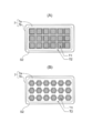
- FIG. 5 shows another specific example of the preform 7.
- the shape of the recess T1 of the second surface S2 is a square shape
- the preform 7 shown in FIG. 5B is the recess T1 of the second surface S2.
- the shape is a honeycomb shape. Any shape of the recess T1 is effective in reducing the warp of the preform 7.
- the area of the convex portion T2 occupying the second surface S2 is 1 ⁇ 2 or less of the area of the concave portion T1, it is possible to effectively achieve both surface accuracy and workability. Further, if the side surface of the concave portion T1 has a draft taper shape of 3 ° or more with respect to the normal line of the bottom surface of the concave portion T1 (cross-hatched portion in FIG. 4F) (in FIG. 4D) Of the angle ⁇ ⁇ 3 °), the releasability can be easily improved.
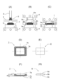
- FIG. 6 shows a fourth embodiment of a method for manufacturing a cover glass plate.
- This manufacturing method is shown in the molding process shown in the cross-sectional views of FIGS. 6A to 6C, the plan view of FIGS. 6D and 6E, and the cross-sectional views of FIGS. 6F and 6G.
- a processing step In the molding process including the dropping process (A), the moving process (B) and the pressing process (C), the preform 7 is formed by the direct pressing method, and in the processing processes (D) to (G), the finished product is formed.
- a cover glass plate 8 is formed.
- the cover glass plate 8 is used, for example, to cover an image display surface of a digital device (for example, a mobile phone, a smartphone, a mobile computer, etc.) having an image display function.
- a digital device for example, a mobile phone, a smartphone, a mobile computer, etc.
- a fixed amount of molten glass 3 is dropped onto the flat portion 1 f of the lower mold 1 in the dropping step (A). That is, the molten glass 3 obtained by melting in the melting furnace is poured out from the platinum nozzle 6 and cut by the blade 5, whereby a certain amount of the molten glass 3 is dropped onto the flat portion 1 f of the lower mold 1.
- the lower mold 1 is heated by the heater 4. Therefore, the molten glass 3 on the flat portion 1f is held and controlled in a state where a predetermined viscosity is maintained.
- the lower mold 1 is moved to a predetermined position below the upper mold 2, and the outer mold 9 is disposed between the upper mold 2 and the lower mold 1.
- the outer mold 9 is disposed on the lower mold 1 so as to surround the molten glass 3.
- a rectangular opening 9h is formed above the outer mold 9, and the upper mold 2 can be fitted into the opening 9h.
- the upper mold 2 is heated by the heater 4 so that the molten glass 3 is not rapidly cooled by the upper mold 2. Therefore, the molten glass 3 on the flat portion 1 f is held and controlled in a state where a predetermined viscosity is maintained even when it contacts the upper mold 2.
- the process proceeds to the pressing process (C).
- the upper mold 2 is lowered, and the molten glass 3 on the flat portion 1 f of the lower mold 1 is pressed by the upper mold 2, so that the molten glass 3 is formed into the upper mold 2.
- the pre-molded body 7 having the protruding portion 7b is formed by filling the concave portion 2a and protruding from the concave portion 2a between the upper mold 2 and the lower mold 1. At this time, the expansion of the protruding portion 7b is regulated by the inner wall surface 9a (FIG. 6B) of the outer mold 9, and the molten glass 3 is filled into the mold inner space.
- the molding surface can be transferred to the preform 7 up to the outermost periphery of the outer surface Sb (FIG. 6B) of the upper mold 2.
- the molten glass 3 is raised upward along the outer periphery of the upper mold 2 in order to make the filling of the molten glass 3 into the recess 2a more reliable.
- the molten glass 3 may be regulated so as not to rise above the position of the external surface Sb.
- the transfer can be performed reliably, a molding surface having a predetermined shape can be obtained easily, reliably and stably. Further, since the deviation of the molten glass 3 is reduced, the temperature distribution is made uniform and the surface accuracy is improved. Furthermore, since the mold inner space is constant, the thickness of the preform 7 is stabilized if the dropping volume of the molten glass 3 is made constant to some extent. In addition, by setting the clearance between the molds to a predetermined size, it is possible to easily discharge air from the mold inner space while holding the molten glass 3 in the mold inner space.
- the preformed body 7 includes a molded body body 7a and a protruding portion 7b (shaded portion).
- the protruding portion 7b which is an unnecessary portion, is completely removed from the preform 7 (that is, until the outer peripheral surface of the molded body 7a is reached). Only the molded body 7a remains. That is, as shown in FIGS. 6E and 6G, a cover glass plate 8 as a finished product is formed.
- the outer frame shape of the cover glass plate 8 is determined by the recess 2a of the upper mold 2, if the protruding portion 7b is completely removed from the preform 7 by surface grinding or surface polishing in the processing step, the outer frame of the cover glass plate 8 There is no need to perform processing (for example, four-frame outline processing corresponding to the rectangle of the image display surface). Further, since the surface shape of the cover glass plate 8 is determined by the recess 2a of the upper mold 2, there is no need to perform post-processing on the surface of the cover glass plate. Therefore, according to the configuration of this embodiment, the thin cover glass plate 8 having any outer frame shape and surface shape can be obtained without performing the outer frame processing of the cover glass plate 8 and the post-processing of the cover glass plate surface. It can be easily manufactured.
- a molding surface molded by the upper mold 2 (molding surface molded by the internal surface Sa or the external surface Sb) may be used.
- a jig may be removably attached to the reference plane to perform surface grinding / planar polishing.
- the surface 7s (FIGS. 6C and 6F) formed by the flat portion 1f of the lower mold 1 has a concave portion T1 and a convex portion as in the second surface S2 shown in FIGS.
- the part T2 may be provided. Providing the concave portion T1 and the convex portion T2 is effective in reducing warpage of the preform 7 as described above.
- the shape of the upper surface 8 a of the cover glass plate 8 is determined by the shape of the recess 2 a filled with the molten glass 3. Therefore, as shown in FIG. 6B, if the surface shape of a part (or the whole) of the recess 2a is a curved surface, the surface shape of a part (or the whole) of the upper surface 8a of the cover glass plate 8 is changed. Can be curved. Therefore, according to the configuration of this embodiment, it is possible to easily meet the needs for changing the specification of the surface of the cover glass plate 8 from a flat surface to a curved surface.
- the mirror surface of the upper surface 8a and the side surface 8b acts in a direction to reduce the releasability with respect to the upper mold 2, but the releasability with respect to the upper mold 2 is improved by the presence of the protruding portion 7b. For this reason, it becomes possible to keep stably the state in which the preform 7 was mounted on the lower mold 1 after the pressing step (C), and it becomes easy to pick up the preform 7 from the lower mold 1. Further, when the outer surface Sb (FIG. 6B) of the upper mold 2 that contacts the protruding portion 7b in the pressing step (C) is made rougher than the inner surface Sa of the recess 2a (FIG. 6B), molding is performed. Separation of the rough surface portion occurs due to the glass shrinking action after completion, and release of the contact surface of the preformed body is promoted, so that the mold release property of the preformed body 7 can be effectively improved.
- the thickness d1 of the cover glass plate 8 (FIG. 6F) is preferably 0.2 to 1.5 mm, and more preferably 0.7 to 1.0 mm.
- the thickness d2 (FIG. 6F) of the protruding portion 7b located below the molded body 7a is preferably about 0.5 to 1.0 mm. If the protruding portion 7b is too thin, the protruding portion 7b is easily broken and the shape accuracy of the side surface 8b is lowered.
- the protruding portion 7b is too thick, the time required for surface grinding / planar polishing becomes longer. In addition, as the volume increases, the amount of sink increases, which may cause deterioration of the molding surface. If the protruding portion 7b does not occur, a space may be generated in the concave surface of the upper mold, and high-precision molding may not be possible, and volume control becomes difficult when performing stable molding.
Landscapes
- Engineering & Computer Science (AREA)
- Chemical & Material Sciences (AREA)
- Mechanical Engineering (AREA)
- Manufacturing & Machinery (AREA)
- Materials Engineering (AREA)
- Organic Chemistry (AREA)
- Ceramic Engineering (AREA)
- Inorganic Chemistry (AREA)
- Surface Treatment Of Glass (AREA)
- Re-Forming, After-Treatment, Cutting And Transporting Of Glass Products (AREA)
- Devices For Indicating Variable Information By Combining Individual Elements (AREA)
Abstract
カバーガラス板の製造方法であって、滴下工程とプレス工程と加工工程を有する。滴下工程では、下金型に溶融ガラスを滴下する。プレス工程では、下金型上の溶融ガラスを、凹部を有する上金型でプレスすることにより、溶融ガラスを上金型の凹部に充填して、更に凹部から上金型と下金型との間にはみ出させて、上金型の凹部形状が転写された第1面を有する成形体本体と、成形体本体以外の部分であって下金型形状が転写された第2面を有するはみ出し部分と、からなる予備成形体を形成する。加工工程では、はみ出し部分を予備成形体からすべて取り除く。
Description
本発明はカバーガラス板の製造方法に関するものであり、例えばスマートフォンの画像表示面に設けられるカバーガラス板の製造方法に関するものである。
画像表示機能を有するデジタル機器(例えば、携帯電話,スマートフォン,モバイルコンピュータ等)には、その画像表示面を保護するためのカバーガラス板が通常設けられる。そのカバーガラス板は、平板状に成形された大面積の板ガラスを所定のサイズに切断することにより製造される。このため、板ガラスの切断後にはその外形枠加工が必要になる。つまり、矩形の板ガラスの4つの角や四辺を構成する側面の境界を滑らかに面取りしたり丸めたりする外形枠加工が必要になる(例えば、特許文献1参照。)。また、カバーガラス板の表面を平面から曲面へと仕様変更するニーズが近年高まってきているが、平板状に成形された板ガラスの表面を曲面化するには後加工が必要になる。
しかし、カバーガラス板の外形枠加工やカバーガラス板表面の後加工を行おうとすると、製造工程の増大や複雑化が生じてしまい、その結果としてコストアップを招くことになる。
本発明はこのような状況に鑑みてなされたものであって、その目的は、カバーガラス板の外形枠加工やカバーガラス板表面の後加工を行わずに、任意の外枠形状及び表面形状を有するカバーガラス板を容易に製造することを可能とする、カバーガラス板の製造方法を提供することにある。
上記目的を達成するために、本発明のカバーガラス板の製造方法は、下金型に溶融ガラスを滴下する滴下工程と、前記下金型上の溶融ガラスを、凹部を有する上金型でプレスすることにより、前記溶融ガラスを上金型の前記凹部に充填して、更に前記凹部から上金型と下金型との間にはみ出させて、前記上金型の凹部形状が転写された第1面を有する成形体本体と、成形体本体以外の部分であって下金型形状が転写された第2面を有するはみ出し部分と、からなる予備成形体を形成するプレス工程と、前記はみ出し部分を前記予備成形体からすべて取り除く加工工程と、を有することを特徴とする。
前記プレス工程において、前記上金型の凹部でカバーガラス板の上面及び側面を形成し、前記加工工程において、前記第2面を平面研削又は平面研磨することによりカバーガラス板の下面を形成することが好ましい。
前記プレス工程において、前記下金型は凹部を有し、前記はみ出し部分の第2面に凹部及び凸部を形成することが好ましい。
前記プレス工程において、前記第2面の最外周に前記凸部が設けられることが好ましい。
前記第2面に占める前記凸部の面積が、前記第2面全体の1/4以上であることが好ましい。
前記プレス工程において、前記第2面には長方形状の前記凹部と、該凹部の周囲を取り囲むように前記第2面の最外周全域にわたって前記凸部と、が設けられることが好ましい。
前記第2面の凹部の形状が円形状,スクエア形状,ハニカム形状又はメッシュ形状であることが好ましい。
前記第2面に占める前記凸部の面積が、前記第2面に占める前記凹部の面積の1/2以下であることが好ましい。
前記第2面の凹部の側面が、その凹部の底面の法線に対して3°以上の抜きテーパ形状を有することが好ましい。
前記上金型の凹部の一部又は全体の面形状が曲面であり、前記第1面の一部又は全体の面形状が曲面であることが好ましい。
前記プレス工程において前記はみ出し部分と接触する前記上金型の表面が、前記上金型の凹部の表面よりも粗くなっていることが好ましい。
前記プレス工程において、前記上金型と前記下金型との間に外金型を配置して、その外金型で前記はみ出し部分の広がりを規制することが好ましい。
カバーガラス板の外枠形状は上金型の凹部によって決まるため、加工工程における平面研削又は平面研磨により、はみ出し部分を予備成形体からすべて取り除くと、カバーガラス板の外形枠加工を行う必要がなくなる。また、カバーガラス板の表面形状も上金型の凹部によって決まるため、カバーガラス板表面の後加工を行う必要がない。したがって、本発明によれば、カバーガラス板の外形枠加工やカバーガラス板表面の後加工を行わずに、任意の外枠形状及び表面形状を有するカバーガラス板を容易に製造することが可能である。
以下、本発明を実施したカバーガラス板の製造方法を、図面を参照しつつ説明する。なお、実施の形態,具体例等の相互で同一の部分や相当する部分には同一の符号を付して重複説明を適宜省略する。
〈第1の実施の形態〉
図1に、カバーガラス板の製造方法の第1の実施の形態を示す。この製造方法は、図1(A)~(C)の断面図に示す成形工程と、図1(D)及び(E)の平面図並びに図1(F)及び(G)の断面図に示す加工工程と、を有している。滴下工程(A),移動工程(B)及びプレス工程(C)を含む成形工程では、ダイレクトプレス法によって予備成形体(板ガラスブランク)7が形成され、また、加工工程(D)~(G)では、完成品としてのカバーガラス板8が形成される。このカバーガラス板8は、例えば、画像表示機能を有するデジタル機器(例えば、携帯電話,スマートフォン,モバイルコンピュータ等)の画像表示面を覆うために用いられる。
図1に、カバーガラス板の製造方法の第1の実施の形態を示す。この製造方法は、図1(A)~(C)の断面図に示す成形工程と、図1(D)及び(E)の平面図並びに図1(F)及び(G)の断面図に示す加工工程と、を有している。滴下工程(A),移動工程(B)及びプレス工程(C)を含む成形工程では、ダイレクトプレス法によって予備成形体(板ガラスブランク)7が形成され、また、加工工程(D)~(G)では、完成品としてのカバーガラス板8が形成される。このカバーガラス板8は、例えば、画像表示機能を有するデジタル機器(例えば、携帯電話,スマートフォン,モバイルコンピュータ等)の画像表示面を覆うために用いられる。
まず、滴下工程(A)で下金型1の平面部1fに一定量の溶融ガラス3を滴下する。つまり、溶融炉で溶かして得られた溶融ガラス3を、白金ノズル6から流し出してブレード5で切断することにより、一定量の溶融ガラス3を下金型1の平面部1f上に滴下する。溶融ガラス3が下金型1で急冷されないようにするため、下金型1はヒータ4で加熱されている。したがって、平面部1f上の溶融ガラス3は所定の粘度が保たれた状態に保持・制御される。
次の移動工程(B)では、下金型1を上金型2の下方所定位置に移動させる。上金型2も下金型1と同様、溶融ガラス3が上金型2で急冷されないようにするため、ヒータ4で加熱されている。したがって、平面部1f上の溶融ガラス3は上金型2に接触しても所定の粘度が保たれた状態に保持・制御される。
移動工程(B)で下金型1を所定時間待機させた後、プレス工程(C)に移行する。プレス工程(C)では、上金型2を下降させ、下金型1の平面部1f上の溶融ガラス3を上金型2でプレスすることにより、溶融ガラス3を上金型2の成形用の凹部2aに充填し、更に凹部2aから上金型2と下金型1との間にはみ出させて、そのはみ出し部分7bを有する予備成形体7を形成する。このように、はみ出させて成形することにより、上金型2の外部表面Sb(図1(B))の最外周まで成形面を予備成形体7に転写させることができる。
プレス工程(C)で得られた予備成形体7を離型して取り出したら、加工工程(D)~(G)に移行する。予備成形体7は、図1(D),(F)に示すように、成形体本体7aとはみ出し部分7b(斜線部分)から成っている。加工工程で、平面研削,平面研磨のうちの少なくとも一方を行うことにより、不要部分であるはみ出し部分7bを予備成形体7からすべて取り除くと(つまり、成形体本体7aの外枠周面に至るまで取り除く。)、成形体本体7aのみが残る。つまり、図1(E),(G)に示すように、完成品としてのカバーガラス板8が形成される。
はみ出し部分7bに対する平面研削・平面研磨は、平面部1fとの接触面7sに対して行われ、その際、複数個の予備成形体7をまとめて研磨パッドで粗く平面研削した後、更に細かく平面研磨していくことにより行われる。平面研削から平面研磨への切り替えは、平面部1fとの接触面7sに対して用いる研磨液を変えることにより容易に行うことができる。なお、カバーガラス板8の下面8cを鏡面にする必要が無い場合には、下面8cに皮膜を形成することにより所望の平滑度を得るようにしてもよい。
カバーガラス板8の外枠形状は上金型2の凹部2aによって決まるため、加工工程における平面研削又は平面研磨により、はみ出し部分7bを予備成形体7からすべて取り除くと、カバーガラス板8の外形枠加工(例えば、画像表示面の矩形に対応した4面の外形枠加工)を行う必要がなくなる。また、カバーガラス板8の表面形状も上金型2の凹部2aによって決まるため、カバーガラス板表面の後加工を行う必要がない。したがって、この実施の形態の構成によれば、カバーガラス板8の外形枠加工やカバーガラス板表面の後加工を行わずに、任意の外枠形状及び表面形状を有する薄肉のカバーガラス板8を容易に製造することが可能である。
下金型1の平面部1fと上金型2の成形用の凹部2aとの位置関係は高い精度で調整可能であるため、加工工程におけるはみ出し部分7bの平面研削又は平面研磨を、プレス工程において下金型1の平面部1fと接触していた面7s(図1(C),(F))に対して行うと、加工工程における平面研削又は平面研磨を高精度に行うことが可能である。したがって、この実施の形態の構成によれば、はみ出し部分7bのみを予備成形体7からすべて取り除くことが容易に可能である。
予備成形体7からはみ出し部分7bをすべて取り除くと、上金型2の成形用の凹部2aに充填された溶融ガラス3のみから成る部分(すなわち、成形体本体7a)が残り、それが完成品としてのカバーガラス板8となる。カバーガラス板8の下面8cは平面研削又は平面研磨により形成されるが(図1(G))、他の面8a,8bは上金型2の凹部2aで形成されるため、凹部2aの高い精度をカバーガラス板8の上面8a及び側面8bの面精度に反映させることができる。例えば、上面8aと側面8bの境界を滑らかな曲面にする成形が可能である。したがって、この実施の形態の構成によれば、カバーガラス板8における下面8c以外の面8a,8bの精度を制御するとともに向上させることが可能である。そして、この構成は制御の難しい粘性の高いガラスの成形においてとりわけ有効である。
溶融ガラス3が充填される凹部2aの形状により、カバーガラス板8の上面8aの形状が決まる。したがって、図1(B)に示すように、凹部2aの一部(全体でもよい。)の面形状を曲面にすれば、カバーガラス板8の上面8aの一部(又は全体)の面形状を曲面にすることができる。したがって、この実施の形態の構成によれば、カバーガラス板8の表面を平面から曲面へと仕様変更するニーズに簡単に対応することができる。
図2に、予備成形体7の具体例を示す。図2(A)は、図1の成形工程により得られる予備成形体7を示している。つまり、この予備成形体7は成形体本体7aに平面を有するものである。図2(B)は、成形体本体7aが凹面を有する予備成形体7Aを示しており、図2(C)は、成形体本体7aが凸面を有する予備成形体7Bを示している。これらの具体例から分かるように、上金型2の凹部2aの形状のバリエーションを増やせば、多種多様な形状(任意の曲面;凸面,凹面;球面,シリンドリカル面等)のカバーガラス板8を作製することができる。また、図2(C)に示すように成形体本体7aが凸面を有する場合、側面での厚さが薄すぎて画像表示面の矩形に対応した4面の外形枠加工は困難であるが、この実施の形態の構成によれば、側面での厚さが薄すぎても、はみ出し部分7bを平面研削又は平面研磨で予備成形体7からすべて取り除くことが容易に可能である。
上面8a及び側面8bを鏡面にすることは、上金型2に対する離型性を低下させる方向に作用するが、はみ出し部分7bがあることにより上金型2に対する離型性が良くなる。このため、プレス工程(C)後に予備成形体7が下金型1上に載った状態を安定的に保つことが可能となり、下金型1からの予備成形体7のピックアップが容易になる。また、プレス工程(C)においてはみ出し部分7bと接触する上金型2の外部表面Sb(図1(B))を、凹部2aの内部表面Sa(図1(B))よりも粗くすると、成形完了後のガラス収縮作用により粗面部の剥離が発生し、予備成形体の接触面の離型が促進されるため、予備成形体7の離型性を効果的に向上させることが可能となる。
この実施の形態では、カバーガラス板8のサイズとして、縦×横×厚さ(d1)=80×100×0.7(mm)を想定している。カバーガラス板8の厚さd1(図1(F))は0.2~1.5mmが好ましく、0.7~1.0mmが更に好ましい。また、成形体本体7aの厚さd1とのバランスから、はみ出し部分7bの厚さd2(図1(F))は0.5~1.0mm程度が好ましい。はみ出し部分7bが薄すぎると割れやすくなり、側面8bの形状精度が低下する。逆に、はみ出し部分7bが厚すぎると、平面研削・平面研磨に要する時間が長くなってしまう。また、体積が大きくなるにしたがってひけ量が増大してしまい、成形面の劣化が生じるおそれがある。はみ出し部分7bが生じないようにすると、上型の凹面内に空間が生じて高精度成型ができなくなるおそれがあり、安定した成型を行う上で体積制御が困難になる。
〈第2の実施の形態〉
図3に、カバーガラス板の製造方法の第2の実施の形態を示す。この製造方法は、図3(A)~(C)の断面図に示す成形工程と、図3(D)及び(E)の断面図並びに図3(F)及び(G)の下面図に示す加工工程と、を有している。滴下工程(A),移動工程(B)及びプレス工程(C)を含む成形工程では、ダイレクトプレス法によって予備成形体7が形成され、また、加工工程(D)~(G)では、完成品としてのカバーガラス板8が形成される。このカバーガラス板8は、例えば、画像表示機能を有するデジタル機器(例えば、携帯電話,スマートフォン,モバイルコンピュータ等)の画像表示面を覆うために用いられる。
図3に、カバーガラス板の製造方法の第2の実施の形態を示す。この製造方法は、図3(A)~(C)の断面図に示す成形工程と、図3(D)及び(E)の断面図並びに図3(F)及び(G)の下面図に示す加工工程と、を有している。滴下工程(A),移動工程(B)及びプレス工程(C)を含む成形工程では、ダイレクトプレス法によって予備成形体7が形成され、また、加工工程(D)~(G)では、完成品としてのカバーガラス板8が形成される。このカバーガラス板8は、例えば、画像表示機能を有するデジタル機器(例えば、携帯電話,スマートフォン,モバイルコンピュータ等)の画像表示面を覆うために用いられる。
まず、滴下工程(A)で凹部1aを有する下金型1に一定量の溶融ガラス3を滴下する。つまり、溶融炉で溶かして得られた溶融ガラス3を、白金ノズル6から流し出してブレード5で切断することにより、一定量の溶融ガラス3を下金型1上に滴下する。溶融ガラス3が下金型1で急冷されないようにするため、下金型1はヒータ4で加熱されている。したがって、下金型1上の溶融ガラス3は所定の粘度が保たれた状態に保持・制御される。
次の移動工程(B)では、下金型1を上金型2の下方所定位置に移動させる。上金型2も下金型1と同様、溶融ガラス3が上金型2で急冷されないようにするため、ヒータ4で加熱されている。したがって、下金型1上の溶融ガラス3は上金型2に接触しても所定の粘度が保たれた状態に保持・制御される。
移動工程(B)で下金型1を所定時間待機させた後、プレス工程(C)に移行する。プレス工程(C)では、成形用の凹部2aを有する上金型2を下降させ、下金型1の上の溶融ガラス3を上金型2でプレスすることにより、溶融ガラス3を上金型2の成形用の凹部2aに充填し、更に凹部2aから上金型2と下金型1との間及び凹部1a内にはみ出させて、そのはみ出し部分7bを有する予備成形体7を形成する。このように、上金型2と下金型1との間にはみ出させて成形することにより、上金型2の外部表面Sb(図3(B))まで成形面を予備成形体7に転写させることができる。
プレス工程(C)で得られた予備成形体7を離型して取り出したら、加工工程(D)~(G)に移行する。予備成形体7は、図3(D),(F)に示すように、成形体本体7aとはみ出し部分7b(図3(D)中の斜線部分)から成っている。上金型2の成形用の凹部2aに充填された溶融ガラス3で第1面S1(成形面)が形成されており、下金型1の凹部1aに充填された溶融ガラス3で、長方形状の凹部T1とその周囲を取り囲むロの字形状の凸部T2とを有する第2面S2(被加工面)が形成されている。加工工程で、平面研削,平面研磨のうちの少なくとも一方を行うことにより、不要部分であるはみ出し部分7bを予備成形体7からすべて取り除くと(つまり、成形体本体7aの外枠周面に至るまで取り除く。)、成形体本体7aのみが残る。つまり、図3(E),(G)に示すように、完成品としてのカバーガラス板8が形成される。
はみ出し部分7bに対する平面研削・平面研磨は、第2面S2に対して行われ、その際、複数個の予備成形体7をまとめて研磨パッドあるいは研磨砥石で粗く平面研削した後、更に細かく研磨パッドにより平面研磨していくことにより行われる。平面研削から平面研磨への切り替えは、第2面S2に対して用いる研磨液を変えることにより容易に行うことができる。なお、カバーガラス板8の下面8cを鏡面にする必要が無い場合には、下面8cに皮膜を形成することにより所望の平滑度を得るようにしてもよい。被膜の例としては、飛散防止フィルムや樹脂コートが挙げられる。
カバーガラス板8の外枠形状は上金型2の凹部2aによって決まるため、加工工程における平面研削又は平面研磨により、はみ出し部分7bを予備成形体7からすべて取り除くと、カバーガラス板8の外形枠加工(例えば、画像表示面の矩形に対応した4面の外形枠加工)を行う必要がなくなる。また、カバーガラス板8の表面形状も上金型2の凹部2aによって決まるため、カバーガラス板表面の後加工を行う必要がない。したがって、この実施の形態の構成によれば、カバーガラス板8の外形枠加工やカバーガラス板表面の後加工を行わずに、任意の外枠形状及び表面形状を有する薄肉のカバーガラス板8を容易に製造することが可能である。
下金型1の凹部1aと上金型2の成形用の凹部2aとの位置関係は高い精度で調整可能であるため、加工工程におけるはみ出し部分7bの平面研削又は平面研磨を、第2面S2(図3(D),(F))に対して行うと、加工工程における平面研削又は平面研磨を高精度に行うことが可能である。したがって、この実施の形態の構成によれば、はみ出し部分7bのみを予備成形体7からすべて取り除くことが容易に可能である。
予備成形体7からはみ出し部分7bをすべて取り除くと、上金型2の成形用の凹部2aに充填された溶融ガラス3のみから成る部分(すなわち、成形体本体7a)が残り、それが完成品としてのカバーガラス板8となる。カバーガラス板8の下面8cは平面研削又は平面研磨により形成されるが(図3(E))、他の面8a,8bは上金型2の凹部2aで形成されるため、凹部2aの高い精度をカバーガラス板8の上面8a及び側面8bの面精度に反映させることができる。例えば、上面8aと側面8bの境界を滑らかな曲面にする成形が可能である。したがって、この実施の形態の構成によれば、カバーガラス板8における下面8c以外の面8a,8bの精度を制御するとともに向上させることが可能である。そして、この構成は制御の難しい粘性の高いガラスの成形においてとりわけ有効である。
溶融ガラス3が充填される凹部2aの形状により、カバーガラス板8の上面8aの形状が決まる。したがって、図3(B)に示すように、凹部2aの一部(全体でもよい。)の面形状を曲面にすれば、カバーガラス板8の上面8aの一部(又は全体)の面形状を曲面にすることができる。したがって、この実施の形態の構成によれば、カバーガラス板8の表面を平面から曲面へと仕様変更するニーズに簡単に対応することができる。
予備成形体7は、成形体本体7aに平面を有するものに限らず、成形体本体7aに凹面又は凸面を有するものでもよい。上金型2の凹部2aの形状のバリエーションを増やせば、多種多様な形状(任意の曲面;凸面,凹面;球面,シリンドリカル面等)のカバーガラス板8を作製することができる。成形体本体7aが凸面を有する場合、側面での厚さが薄すぎて画像表示面の矩形に対応した4面の外形枠加工は困難であるが、この実施の形態の構成によれば、側面での厚さが薄すぎても、はみ出し部分7bを平面研削又は平面研磨で予備成形体7からすべて取り除くことが容易に可能である。
上面8a及び側面8bを鏡面にすることは、上金型2に対する離型性を低下させる方向に作用するが、はみ出し部分7bがあることにより上金型2に対する離型性が良くなる。このため、プレス工程(C)後に予備成形体7が下金型1上に載った状態を安定的に保つことが可能となり、下金型1からの予備成形体7のピックアップが容易になる。また、プレス工程(C)においてはみ出し部分7bと接触する上金型2の外部表面Sb(図3(B))を、凹部2aの内部表面Sa(図3(B))よりも粗くすると、成形完了後のガラス収縮作用により粗面部の剥離が発生し、予備成形体の接触面の離型が促進されるため、予備成形体7の離型性を効果的に向上させることが可能となる。
上金型2で形成された第1面S1の裏面である第2面S2に平面研削又は平面研磨を施せば、第1面S1及び第2面S2共に高精度の面形状を得ることができる。しかし、第1面S1の精度を確保するには成形厚みをできるだけ多く確保する必要があり、成形厚みが大きくなるほど研削又は研磨の加工負荷も大きくなってしまう。この実施の形態のように、第2面S2が凹部T1及び凸部T2を有する面であれば、研削又は研磨の加工負荷が軽減され、しかもその凹凸により研磨砥石のドレッシング効果(砥石の目詰まりを解消する効果)も得られる。したがって、第2面S2に凹部T1及び凸部T2を有する予備成形体7(図3(D),(F))を用いれば、平面研削又は平面研磨により第2面S2の所定位置での平面化が容易に可能となるため、加工時間の短縮及び加工コストの低減が可能となり、第1面S1及び第2面S2共に高精度の面形状を有するカバーガラス板8を容易に製造することが可能となる。
この実施の形態のように第2面S2の最外周に凸部T2を配置すれば、中心部分が相対的に薄くなってガラス収縮量が少なくなり、周辺部分のガラスの固化が緩和され、また予備成形体7の反りが低減するため、第1面S1の転写精度を容易に向上させることができる。そして、第2面S2に占める凸部T2の面積が全体の1/4以上であれば、その効果は更に大きくなる。
滴下した溶融ガラスよりも金型温度の方が低いため、滴下後のガラスは固化を開始する。ガラスの周辺部は固化しやすいため、最外周に凸部T2がないと上型でプレスする場合に、ガラスが周辺部に広がらず転写精度が悪くなりやすい。また、プレスされた成形品においても周辺部よりも中心部の方がガラス温度が高い。温度が高いために中心部のガラスの収縮率が周辺部よりも大きいため、プレス終了後(上金型の押し込み終了後)にガラス中心部の収縮量が大きくなり、予備成形体7に対して金型の転写不足や反りが発生する。本実施形態では最外周に凸部T2を設けることで、最外周の厚さが増し熱容量を大きくすることで外周部が冷えにくく、プレス時にガラスが周辺部まで広がりやすくなる。また中心部を外周部に対して相対的に薄くすることで収縮率の大きい中心部と収縮率の小さい周辺部とのバランスをとることができ、予備成形体7全体として均一な収縮量となり、成形の転写性能が向上する。
第2面S2に占める凸部T2の面積が凹部T1の面積の1/2以下であれば、面精度と加工性を効果的に両立させることができる。また、凹部T1の側面が、凹部T1の底面(図3(F)中のクロスハッチング部分)の法線に対して3°以上の抜きテーパ形状を有する構成にすれば(図3(D)中の角度θ≧3°)、離型性を容易に向上させることができる。
〈第3の実施の形態〉
図4に、カバーガラス板の製造方法の第3の実施の形態を示す。この製造方法は、図4(A)~(C)の断面図に示す成形工程と、図4(D)及び(E)の断面図並びに図4(F)及び(G)の下面図に示す加工工程と、を有している。滴下工程(A),移動工程(B)及びプレス工程(C)を含む成形工程では、ダイレクトプレス法によって予備成形体7が形成され、また、加工工程(D)~(G)では、完成品としてのカバーガラス板8が形成される。このカバーガラス板8は、例えば、画像表示機能を有するデジタル機器(例えば、携帯電話,スマートフォン,モバイルコンピュータ等)の画像表示面を覆うために用いられる。
図4に、カバーガラス板の製造方法の第3の実施の形態を示す。この製造方法は、図4(A)~(C)の断面図に示す成形工程と、図4(D)及び(E)の断面図並びに図4(F)及び(G)の下面図に示す加工工程と、を有している。滴下工程(A),移動工程(B)及びプレス工程(C)を含む成形工程では、ダイレクトプレス法によって予備成形体7が形成され、また、加工工程(D)~(G)では、完成品としてのカバーガラス板8が形成される。このカバーガラス板8は、例えば、画像表示機能を有するデジタル機器(例えば、携帯電話,スマートフォン,モバイルコンピュータ等)の画像表示面を覆うために用いられる。
まず、滴下工程(A)で凹部1aを有する下金型1に一定量の溶融ガラス3を滴下する。つまり、溶融炉で溶かして得られた溶融ガラス3を、白金ノズル6から流し出してブレード5で切断することにより、一定量の溶融ガラス3を下金型1上に滴下する。溶融ガラス3が下金型1で急冷されないようにするため、下金型1はヒータ4で加熱されている。したがって、下金型1上の溶融ガラス3は所定の粘度が保たれた状態に保持・制御される。
次の移動工程(B)では、下金型1を上金型2の下方所定位置に移動させる。上金型2も下金型1と同様、溶融ガラス3が上金型2で急冷されないようにするため、ヒータ4で加熱されている。したがって、下金型1上の溶融ガラス3は上金型2に接触しても所定の粘度が保たれた状態に保持・制御される。
移動工程(B)で下金型1を所定時間待機させた後、プレス工程(C)に移行する。プレス工程(C)では、成形用の凹部2aを有する上金型2を下降させ、下金型1の上の溶融ガラス3を上金型2でプレスすることにより、溶融ガラス3を上金型2の成形用の凹部2aに充填し、更に凹部2aから上金型2と下金型1との間及び凹部1a内にはみ出させて、そのはみ出し部分7bを有する予備成形体7を形成する。このように、上金型2と下金型1との間にはみ出させて成形することにより、上金型2の外部表面Sb(図4(B))まで成形面を予備成形体7に転写させることができる。
プレス工程(C)で得られた予備成形体7を離型して取り出したら、加工工程(D)~(G)に移行する。予備成形体7は、図4(D),(F)に示すように、成形体本体7aとはみ出し部分7b(図4(D)中の斜線部分)から成っている。上金型2の成形用の凹部2aに充填された溶融ガラス3で第1面S1(成形面)が形成されており、下金型1の凹部1aに充填された溶融ガラス3で、複数の円形状の凹部T1とそれに対して相対的に突出するように形成された長方形状の凸部T2とを有する第2面S2(被加工面)が形成されている。加工工程で、平面研削,平面研磨のうちの少なくとも一方を行うことにより、不要部分であるはみ出し部分7bを予備成形体7からすべて取り除くと(つまり、成形体本体7aの外枠周面に至るまで取り除く。)、成形体本体7aのみが残る。つまり、図4(E),(G)に示すように、完成品としてのカバーガラス板8が形成される。
はみ出し部分7bに対する平面研削・平面研磨は、第2面S2に対して行われ、その際、複数個の予備成形体7をまとめて研磨パッドあるいは研磨砥石で粗く平面研削した後、更に細かく研磨パッドにより平面研磨していくことにより行われる。平面研削から平面研磨への切り替えは、第2面S2に対して用いる研磨液を変えることにより容易に行うことができる。なお、カバーガラス板8の下面8cを鏡面にする必要が無い場合には、下面8cに皮膜を形成することにより所望の平滑度を得るようにしてもよい。
カバーガラス板8の外枠形状は上金型2の凹部2aによって決まるため、加工工程における平面研削又は平面研磨により、はみ出し部分7bを予備成形体7からすべて取り除くと、カバーガラス板8の外形枠加工(例えば、画像表示面の矩形に対応した4面の外形枠加工)を行う必要がなくなる。また、カバーガラス板8の表面形状も上金型2の凹部2aによって決まるため、カバーガラス板表面の後加工を行う必要がない。したがって、この実施の形態の構成によれば、カバーガラス板8の外形枠加工やカバーガラス板表面の後加工を行わずに、任意の外枠形状及び表面形状を有する薄肉のカバーガラス板8を容易に製造することが可能である。
下金型1の凹部1aと上金型2の成形用の凹部2aとの位置関係は高い精度で調整可能であるため、加工工程におけるはみ出し部分7bの平面研削又は平面研磨を、プレス工程において第2面S2(図4(D),(F))に対して行うと、加工工程における平面研削又は平面研磨を高精度に行うことが可能である。したがって、この実施の形態の構成によれば、はみ出し部分7bのみを予備成形体7からすべて取り除くことが容易に可能である。
予備成形体7からはみ出し部分7bをすべて取り除くと、上金型2の成形用の凹部2aに充填された溶融ガラス3のみから成る部分(すなわち、成形体本体7a)が残り、それが完成品としてのカバーガラス板8となる。カバーガラス板8の下面8cは平面研削又は平面研磨により形成されるが(図4(E))、他の面8a,8bは上金型2の凹部2aで形成されるため、凹部2aの高い精度をカバーガラス板8の上面8a及び側面8bの面精度に反映させることができる。例えば、上面8aと側面8bの境界を滑らかな曲面にする成形が可能である。したがって、この実施の形態の構成によれば、カバーガラス板8における下面8c以外の面8a,8bの精度を制御するとともに向上させることが可能である。そして、この構成は制御の難しい粘性の高いガラスの成形においてとりわけ有効である。
溶融ガラス3が充填される凹部2aの形状により、カバーガラス板8の上面8aの形状が決まる。したがって、図4(B)に示すように、凹部2aの一部(全体でもよい。)の面形状を曲面にすれば、カバーガラス板8の上面8aの一部(又は全体)の面形状を曲面にすることができる。したがって、この実施の形態の構成によれば、カバーガラス板8の表面を平面から曲面へと仕様変更するニーズに簡単に対応することができる。
予備成形体7は、成形体本体7aに平面を有するものに限らず、成形体本体7aに凹面又は凸面を有するものでもよい。上金型2の凹部2aの形状のバリエーションを増やせば、多種多様な形状(任意の曲面;凸面,凹面;球面,シリンドリカル面等)のカバーガラス板8を作製することができる。成形体本体7aが凸面を有する場合、側面での厚さが薄すぎて画像表示面の矩形に対応した4面の外形枠加工は困難であるが、この実施の形態の構成によれば、側面での厚さが薄すぎても、はみ出し部分7bを平面研削又は平面研磨で予備成形体7からすべて取り除くことが容易に可能である。
上面8a及び側面8bを鏡面にすることは、上金型2に対する離型性を低下させる方向に作用するが、はみ出し部分7bがあることにより上金型2に対する離型性が良くなる。このため、プレス工程(C)後に予備成形体7が下金型1上に載った状態を安定的に保つことが可能となり、下金型1からの予備成形体7のピックアップが容易になる。また、プレス工程(C)においてはみ出し部分7bと接触する上金型2の外部表面Sb(図4(B))を、凹部2aの内部表面Sa(図4(B))よりも粗くすると、成形完了後のガラス収縮作用により粗面部の剥離が発生し、予備成形体の接触面の離型が促進されるため、予備成形体7の離型性を効果的に向上させることが可能となる。
上金型2で形成された第1面S1の裏面である第2面S2に平面研削又は平面研磨を施せば、第1面S1及び第2面S2共に高精度の面形状を得ることができる。しかし、第1面S1の精度を確保するには成形厚みをできるだけ多く確保する必要があり、成形厚みが大きくなるほど研削又は研磨の加工負荷も大きくなってしまう。この実施の形態のように、第2面S2が凹部T1及び凸部T2を有する面であれば、研削又は研磨の加工負荷が軽減され、しかもその凹凸により研磨砥石のドレッシング効果(砥石の目詰まりを解消する効果)も得られる。したがって、第2面S2に凹部T1及び凸部T2を有する予備成形体7(図4(D),(F))を用いれば、平面研削又は平面研磨により第2面S2の所定位置での平面化が容易に可能となるため、加工時間の短縮及び加工コストの低減が可能となり、第1面S1及び第2面S2共に高精度の面形状を有するカバーガラス板8を容易に製造することが可能となる。
この実施の形態のように第2面S2の最外周に凸部T2を配置すれば、中心部分が相対的に薄くなってガラス収縮量が少なくなり、周辺部分のガラスの固化が緩和され、また予備成形体7の反りが低減するため、第1面S1の転写精度を容易に向上させることができる。そして、第2面S2に占める凸部T2の面積が全体の1/4以上であれば、その効果は更に大きくなる。予備成形体7の板厚や大きさによってその反り度合いは異なるが、この実施の形態のように円形状の凹部T1を複数(場合によっては1つ)配置することで補強すれば、予備成形体7の反りを効果的に低減することができる。
凹部T1の形状は円形状に限らず、スクエア形状,ハニカム形状,メッシュ形状等の型加工の容易な形状でもよい。図5に、予備成形体7の他の具体例を示す。図5(A)に示す予備成形体7は、第2面S2の凹部T1の形状がスクエア形状になっており、図5(B)に示す予備成形体7は、第2面S2の凹部T1の形状がハニカム形状になっている。いずれの凹部T1の形状も予備成形体7の反りの低減に有効である。
第2面S2に占める凸部T2の面積が凹部T1の面積の1/2以下であれば、面精度と加工性を効果的に両立させることができる。また、凹部T1の側面が、凹部T1の底面(図4(F)中のクロスハッチング部分)の法線に対して3°以上の抜きテーパ形状を有する構成にすれば(図4(D)中の角度θ≧3°)、離型性を容易に向上させることができる。
〈第4の実施の形態〉
図6に、カバーガラス板の製造方法の第4の実施の形態を示す。この製造方法は、図6(A)~(C)の断面図に示す成形工程と、図6(D)及び(E)の平面図並びに図6(F)及び(G)の断面図に示す加工工程と、を有している。滴下工程(A),移動工程(B)及びプレス工程(C)を含む成形工程では、ダイレクトプレス法によって予備成形体7が形成され、また、加工工程(D)~(G)では、完成品としてのカバーガラス板8が形成される。このカバーガラス板8は、例えば、画像表示機能を有するデジタル機器(例えば、携帯電話,スマートフォン,モバイルコンピュータ等)の画像表示面を覆うために用いられる。
図6に、カバーガラス板の製造方法の第4の実施の形態を示す。この製造方法は、図6(A)~(C)の断面図に示す成形工程と、図6(D)及び(E)の平面図並びに図6(F)及び(G)の断面図に示す加工工程と、を有している。滴下工程(A),移動工程(B)及びプレス工程(C)を含む成形工程では、ダイレクトプレス法によって予備成形体7が形成され、また、加工工程(D)~(G)では、完成品としてのカバーガラス板8が形成される。このカバーガラス板8は、例えば、画像表示機能を有するデジタル機器(例えば、携帯電話,スマートフォン,モバイルコンピュータ等)の画像表示面を覆うために用いられる。
まず、滴下工程(A)で下金型1の平面部1fに一定量の溶融ガラス3を滴下する。つまり、溶融炉で溶かして得られた溶融ガラス3を、白金ノズル6から流し出してブレード5で切断することにより、一定量の溶融ガラス3を下金型1の平面部1f上に滴下する。溶融ガラス3が下金型1で急冷されないようにするため、下金型1はヒータ4で加熱されている。したがって、平面部1f上の溶融ガラス3は所定の粘度が保たれた状態に保持・制御される。
次の移動工程(B)では、下金型1を上金型2の下方所定位置に移動させ、上金型2と下金型1との間に外金型9を配置する。このとき、溶融ガラス3を取り囲むように外金型9を下金型1上に配置する。また、外金型9の上方には長方形状の開口部9hが形成されており、開口部9hには上金型2が嵌合可能となっている。上金型2も下金型1と同様、溶融ガラス3が上金型2で急冷されないようにするため、ヒータ4で加熱されている。したがって、平面部1f上の溶融ガラス3は上金型2に接触しても所定の粘度が保たれた状態に保持・制御される。
移動工程(B)で下金型1を所定時間待機させた後、プレス工程(C)に移行する。プレス工程(C)では、上金型2を下降させ、下金型1の平面部1f上の溶融ガラス3を上金型2でプレスすることにより、溶融ガラス3を上金型2の成形用の凹部2aに充填し、更に凹部2aから上金型2と下金型1との間にはみ出させて、そのはみ出し部分7bを有する予備成形体7を形成する。このとき、はみ出し部分7bの広がりは外金型9の内壁面9a(図6(B))で規制されて、金型内空間に溶融ガラス3が充填される。このように、溶融ガラス3をはみ出させて成形することにより、上金型2の外部表面Sb(図6(B))の最外周まで成形面を予備成形体7に転写させることができる。このとき、凹部2aに対する溶融ガラス3の充填をより確実にするため、溶融ガラス3を上金型2の外周に沿って上方にせり上げているが、その規制位置は必要に応じて設定すればよい。例えば、溶融ガラス3を外部表面Sbの位置よりもせり上げないように規制してもよい。
通常、温度分布の不均一な溶融ガラス3の広がり(はみ出し)を均一化することは難しい。このため、凹部2aに対する溶融ガラス3の充填を安定的に行うことは困難である。しかし、上述したように外金型9の内壁面9aで溶融ガラス3の流れを規制すれば、不均一な溶融ガラス3の流れが外金型9で抑制されて、金型内空間を溶融ガラス3が充填部分から未充填部分へと流れるため、凹部2aに対する溶融ガラス3の充填が容易かつ確実になる。
上記のように外金型9ではみ出し部分7bの広がりを規制することにより、成形性をより高めることが可能となる。つまり、転写を確実に行うことができるので、所定形状の成形面が容易・確実・安定的に得られる。また、溶融ガラス3の片寄りが少なくなるので、温度分布が均一化されて面精度が向上する。さらに、金型内空間が一定であるため、溶融ガラス3の滴下体積をある程度一定にすれば、予備成形体7の厚みが安定化する。なお、金型間のクリアランスを所定の大きさに設定することによって、金型内空間に溶融ガラス3を保持しつつ金型内空間からの空気の排出を容易に行うことができる。
プレス工程(C)で得られた予備成形体7を離型して取り出したら、加工工程(D)~(G)に移行する。予備成形体7は、図6(D),(F)に示すように、成形体本体7aとはみ出し部分7b(斜線部分)から成っている。加工工程で、平面研削,平面研磨のうちの少なくとも一方を行うことにより、不要部分であるはみ出し部分7bを予備成形体7からすべて取り除くと(つまり、成形体本体7aの外枠周面に至るまで取り除く。)、成形体本体7aのみが残る。つまり、図6(E),(G)に示すように、完成品としてのカバーガラス板8が形成される。
はみ出し部分7bに対する平面研削・平面研磨は、平面部1fとの接触面7sに対して行われ、その際、複数個の予備成形体7をまとめて研磨パッドで粗く平面研削した後、更に細かく平面研磨していくことにより行われる。平面研削から平面研磨への切り替えは、平面部1fとの接触面7sに対して用いる研磨液を変えることにより容易に行うことができる。なお、カバーガラス板8の下面8cを鏡面にする必要が無い場合には、下面8cに皮膜を形成することにより所望の平滑度を得るようにしてもよい。
カバーガラス板8の外枠形状は上金型2の凹部2aによって決まるため、加工工程における平面研削又は平面研磨により、はみ出し部分7bを予備成形体7からすべて取り除くと、カバーガラス板8の外形枠加工(例えば、画像表示面の矩形に対応した4面の外形枠加工)を行う必要がなくなる。また、カバーガラス板8の表面形状も上金型2の凹部2aによって決まるため、カバーガラス板表面の後加工を行う必要がない。したがって、この実施の形態の構成によれば、カバーガラス板8の外形枠加工やカバーガラス板表面の後加工を行わずに、任意の外枠形状及び表面形状を有する薄肉のカバーガラス板8を容易に製造することが可能である。
下金型1の平面部1fと上金型2の成形用の凹部2aとの位置関係は高い精度で調整可能であるため、加工工程におけるはみ出し部分7bの平面研削又は平面研磨を、プレス工程において下金型1の平面部1fと接触していた面7s(図6(C),(F))に対して行うと、加工工程における平面研削又は平面研磨を高精度に行うことが可能である。したがって、この実施の形態の構成によれば、はみ出し部分7bのみを予備成形体7からすべて取り除くことが容易に可能である。
はみ出し部分7bに対する平面研削・平面研磨の基準面としては、上金型2で成形された成形面(内部表面Sa又は外部表面Sbで成形された成形面)を用いればよい。例えば、成形体本体7a又ははみ出し部分7bの成形平面を基準として、その基準平面に対しジグを取り外し可能に貼って平面研削・平面研磨を行えばよい。また、プレス工程において下金型1の平面部1fで形成される面7s(図6(C),(F))に、図3,図4に示す第2面S2と同様、凹部T1,凸部T2を設けてもよい。凹部T1,凸部T2を設けることは、前述したように予備成形体7の反りの低減に効果がある。
予備成形体7からはみ出し部分7bをすべて取り除くと、上金型2の成形用の凹部2aに充填された溶融ガラス3のみから成る部分(すなわち、成形体本体7a)が残り、それが完成品としてのカバーガラス板8となる。カバーガラス板8の下面8cは平面研削又は平面研磨により形成されるが(図6(G))、他の面8a,8bは上金型2の凹部2aで形成されるため、凹部2aの高い精度をカバーガラス板8の上面8a及び側面8bの面精度に反映させることができる。例えば、上面8aと側面8bの境界を滑らかな曲面にする成形が可能である。したがって、この実施の形態の構成によれば、カバーガラス板8における下面8c以外の面8a,8bの精度を制御するとともに向上させることが可能である。そして、この構成は制御の難しい粘性の高いガラスの成形においてとりわけ有効である。
溶融ガラス3が充填される凹部2aの形状により、カバーガラス板8の上面8aの形状が決まる。したがって、図6(B)に示すように、凹部2aの一部(全体でもよい。)の面形状を曲面にすれば、カバーガラス板8の上面8aの一部(又は全体)の面形状を曲面にすることができる。したがって、この実施の形態の構成によれば、カバーガラス板8の表面を平面から曲面へと仕様変更するニーズに簡単に対応することができる。
上面8a及び側面8bを鏡面にすることは、上金型2に対する離型性を低下させる方向に作用するが、はみ出し部分7bがあることにより上金型2に対する離型性が良くなる。このため、プレス工程(C)後に予備成形体7が下金型1上に載った状態を安定的に保つことが可能となり、下金型1からの予備成形体7のピックアップが容易になる。また、プレス工程(C)においてはみ出し部分7bと接触する上金型2の外部表面Sb(図6(B))を、凹部2aの内部表面Sa(図6(B))よりも粗くすると、成形完了後のガラス収縮作用により粗面部の剥離が発生し、予備成形体の接触面の離型が促進されるため、予備成形体7の離型性を効果的に向上させることが可能となる。
この実施の形態では、カバーガラス板8のサイズとして、縦×横×厚さ(d1)=80×100×0.7(mm)を想定している。カバーガラス板8の厚さd1(図6(F))は0.2~1.5mmが好ましく、0.7~1.0mmが更に好ましい。また、成形体本体7aの厚さd1とのバランスから、成形体本体7aの下方に位置するはみ出し部分7bの厚さd2(図6(F))は0.5~1.0mm程度が好ましい。はみ出し部分7bが薄すぎると割れやすくなり、側面8bの形状精度が低下する。逆に、はみ出し部分7bが厚すぎると、平面研削・平面研磨に要する時間が長くなってしまう。また、体積が大きくなるにしたがってひけ量が増大してしまい、成形面の劣化が生じるおそれがある。はみ出し部分7bが生じないようにすると、上型の凹面内に空間が生じて高精度成型ができなくなるおそれがあり、安定した成型を行う上で体積制御が困難になる。
1 下金型
1f 平面部
1a 凹部
2 上金型
2a 凹部
3 溶融ガラス
4 ヒータ
5 ブレード
6 白金ノズル
7,7A,7B 予備成形体
7a 成形体本体
7b はみ出し部分
7s 接触面
8 カバーガラス板
8a 上面
8b 側面
8c 下面
9 外金型
9a 内壁面
9h 開口部
T1 凹部
T2 凸部
S1 第1面(成形面)
S2 第2面(被加工面)
Sa 内部表面
Sb 外部表面
1f 平面部
1a 凹部
2 上金型
2a 凹部
3 溶融ガラス
4 ヒータ
5 ブレード
6 白金ノズル
7,7A,7B 予備成形体
7a 成形体本体
7b はみ出し部分
7s 接触面
8 カバーガラス板
8a 上面
8b 側面
8c 下面
9 外金型
9a 内壁面
9h 開口部
T1 凹部
T2 凸部
S1 第1面(成形面)
S2 第2面(被加工面)
Sa 内部表面
Sb 外部表面
Claims (12)
- 下金型に溶融ガラスを滴下する滴下工程と、
前記下金型上の溶融ガラスを、凹部を有する上金型でプレスすることにより、前記溶融ガラスを上金型の前記凹部に充填して、更に前記凹部から上金型と下金型との間にはみ出させて、前記上金型の凹部形状が転写された第1面を有する成形体本体と、成形体本体以外の部分であって下金型形状が転写された第2面を有するはみ出し部分と、からなる予備成形体を形成するプレス工程と、
前記はみ出し部分を前記予備成形体からすべて取り除く加工工程と、
を有することを特徴とするカバーガラス板の製造方法。 - 前記プレス工程において、前記上金型の凹部でカバーガラス板の上面及び側面を形成し、前記加工工程において、前記第2面を平面研削又は平面研磨することによりカバーガラス板の下面を形成することを特徴とする請求項1記載のカバーガラス板の製造方法。
- 前記プレス工程において、前記下金型は凹部を有し、前記はみ出し部分の第2面に凹部及び凸部を形成することを特徴とする請求項2記載のカバーガラス板の製造方法。
- 前記プレス工程において、前記第2面の最外周に前記凸部が設けられることを特徴とする請求項3記載のカバーガラス板の製造方法。
- 前記第2面に占める前記凸部の面積が、前記第2面全体の1/4以上であることを特徴とする請求項4記載のカバーガラス板の製造方法。
- 前記プレス工程において、前記第2面には長方形状の前記凹部と、該凹部の周囲を取り囲むように前記第2面の最外周全域にわたって前記凸部と、が設けられることを特徴とする請求項4又は5記載のカバーガラス板の製造方法。
- 前記第2面の凹部の形状が円形状,スクエア形状,ハニカム形状又はメッシュ形状であることを特徴とする請求項3~5のいずれか1項に記載のカバーガラス板の製造方法。
- 前記第2面に占める前記凸部の面積が、前記第2面に占める前記凹部の面積の1/2以下であることを特徴とする請求項3~7のいずれか1項に記載のカバーガラス板の製造方法。
- 前記第2面の凹部の側面が、その凹部の底面の法線に対して3°以上の抜きテーパ形状を有することを特徴とする請求項3~8のいずれか1項に記載のカバーガラス板の製造方法。
- 前記上金型の凹部の一部又は全体の面形状が曲面であり、前記第1面の一部又は全体の面形状が曲面であることを特徴とする請求項1~9のいずれか1項に記載のカバーガラス板の製造方法。
- 前記プレス工程において前記はみ出し部分と接触する前記上金型の表面が、前記上金型の凹部の表面よりも粗くなっていることを特徴とする請求項1~10いずれか1項に記載のカバーガラス板の製造方法。
- 前記プレス工程において、前記上金型と前記下金型との間に外金型を配置して、その外金型で前記はみ出し部分の広がりを規制することを特徴とする請求項1~11のいずれか1項に記載のカバーガラス板の製造方法。
Priority Applications (2)
| Application Number | Priority Date | Filing Date | Title |
|---|---|---|---|
| CN201280061586.1A CN103998389A (zh) | 2011-12-15 | 2012-09-21 | 玻璃盖板的制造方法 |
| US14/357,889 US20140283553A1 (en) | 2011-12-15 | 2012-09-21 | Method of manufacturing cover glass plate |
Applications Claiming Priority (2)
| Application Number | Priority Date | Filing Date | Title |
|---|---|---|---|
| JP2011-274281 | 2011-12-15 | ||
| JP2011274281A JP5435018B2 (ja) | 2011-12-15 | 2011-12-15 | 板ガラスブランクス,その製造方法及びカバーガラス板の製造方法 |
Publications (1)
| Publication Number | Publication Date |
|---|---|
| WO2013088808A1 true WO2013088808A1 (ja) | 2013-06-20 |
Family
ID=48612267
Family Applications (1)
| Application Number | Title | Priority Date | Filing Date |
|---|---|---|---|
| PCT/JP2012/074171 WO2013088808A1 (ja) | 2011-12-15 | 2012-09-21 | カバーガラス板の製造方法 |
Country Status (4)
| Country | Link |
|---|---|
| US (1) | US20140283553A1 (ja) |
| JP (1) | JP5435018B2 (ja) |
| CN (1) | CN103998389A (ja) |
| WO (1) | WO2013088808A1 (ja) |
Families Citing this family (4)
| Publication number | Priority date | Publication date | Assignee | Title |
|---|---|---|---|---|
| JP5434948B2 (ja) * | 2011-03-31 | 2014-03-05 | コニカミノルタ株式会社 | カバーガラス板の製造方法 |
| US9981844B2 (en) | 2012-03-08 | 2018-05-29 | Infineon Technologies Ag | Method of manufacturing semiconductor device with glass pieces |
| DE102019207119A1 (de) * | 2019-05-16 | 2020-11-19 | Realization Desal Ag | Verfahren zum Herstellen eines Uhrglases mit mindestens einer Ausnehmung und Werkzeug für ein derartiges Verfahren |
| DE102019216893A1 (de) * | 2019-10-31 | 2021-05-06 | Flabeg Deutschland Gmbh | Verfahren zur Umformung eines Flachglases in ein Glasbauteil und Umformwerkzeug zur Verwendung in dem Verfahren |
Citations (1)
| Publication number | Priority date | Publication date | Assignee | Title |
|---|---|---|---|---|
| JP2005107410A (ja) * | 2003-10-01 | 2005-04-21 | Asahi Techno Glass Corp | 板状ガラス光学素子及びその製造方法 |
Family Cites Families (14)
| Publication number | Priority date | Publication date | Assignee | Title |
|---|---|---|---|---|
| DE69701503T2 (de) * | 1996-12-26 | 2000-11-09 | Hoya Corp., Tokio/Tokyo | Verfahren zum Herstellen eines Glasproduktes durch Pressformen |
| KR19990068730A (ko) * | 1999-06-15 | 1999-09-06 | 성필호 | 평판디스플레이의커버그라스 |
| DE19956654B4 (de) * | 1999-11-25 | 2005-04-21 | Fraunhofer-Gesellschaft zur Förderung der angewandten Forschung e.V. | Verfahren zur Strukturierung von Oberflächen von mikromechanischen und/oder mikrooptischen Bauelementen und/oder Funktionselementen aus glasartigen Materialien |
| JP2003248106A (ja) * | 2002-02-25 | 2003-09-05 | Mitsubishi Electric Corp | 光学素子 |
| JP3849669B2 (ja) * | 2003-05-19 | 2006-11-22 | コニカミノルタオプト株式会社 | 光学素子製造方法 |
| JP4569365B2 (ja) * | 2005-04-14 | 2010-10-27 | コニカミノルタオプト株式会社 | ビーム整形素子の製造方法、該方法により得られるビーム整形素子 |
| WO2008053860A1 (fr) * | 2006-10-31 | 2008-05-08 | Hoya Corporation | Filière de formage sous presse de moule et procédé de fabrication d'article moulé |
| CN101588996B (zh) * | 2007-01-16 | 2012-02-22 | 柯尼卡美能达精密光学株式会社 | 玻璃基板成型用模具、玻璃基板的制造方法、信息记录介质玻璃基板的制造方法及信息记录介质的制造方法 |
| JP5294150B2 (ja) * | 2009-01-23 | 2013-09-18 | 日本電気硝子株式会社 | 強化ガラスの製造方法 |
| JP2010235423A (ja) * | 2009-03-31 | 2010-10-21 | Ohara Inc | ガラス成形体の製造方法及びガラス成形装置 |
| US8713968B2 (en) * | 2010-05-03 | 2014-05-06 | Corning Incorporated | Method and apparatus for making a 3D glass article |
| JP5657586B2 (ja) * | 2011-03-30 | 2015-01-21 | Hoya株式会社 | 電子機器用カバーガラスブランクの製造方法および電子機器用カバーガラスの製造方法 |
| JP5434948B2 (ja) * | 2011-03-31 | 2014-03-05 | コニカミノルタ株式会社 | カバーガラス板の製造方法 |
| JP5776417B2 (ja) * | 2011-07-29 | 2015-09-09 | 旭硝子株式会社 | ガラスの成形方法 |
-
2011
- 2011-12-15 JP JP2011274281A patent/JP5435018B2/ja not_active Expired - Fee Related
-
2012
- 2012-09-21 US US14/357,889 patent/US20140283553A1/en not_active Abandoned
- 2012-09-21 CN CN201280061586.1A patent/CN103998389A/zh active Pending
- 2012-09-21 WO PCT/JP2012/074171 patent/WO2013088808A1/ja active Application Filing
Patent Citations (1)
| Publication number | Priority date | Publication date | Assignee | Title |
|---|---|---|---|---|
| JP2005107410A (ja) * | 2003-10-01 | 2005-04-21 | Asahi Techno Glass Corp | 板状ガラス光学素子及びその製造方法 |
Also Published As
| Publication number | Publication date |
|---|---|
| JP5435018B2 (ja) | 2014-03-05 |
| JP2013124207A (ja) | 2013-06-24 |
| CN103998389A (zh) | 2014-08-20 |
| US20140283553A1 (en) | 2014-09-25 |
Similar Documents
| Publication | Publication Date | Title |
|---|---|---|
| WO2014050376A1 (ja) | ガラス部品の製造方法 | |
| WO2013088808A1 (ja) | カバーガラス板の製造方法 | |
| TWI387564B (zh) | 形成一光學元件與基板之方法及裝置以及成型工具 | |
| TWI607974B (zh) | Glass shaped body manufacturing method and forming die | |
| TW200932470A (en) | Rectangular optical glass lens and manufacturing method thereof | |
| JP3849669B2 (ja) | 光学素子製造方法 | |
| KR101170586B1 (ko) | 광학 소자의 제조 방법 | |
| US9309141B2 (en) | Method of manufacturing optical element and optical element | |
| JP5434948B2 (ja) | カバーガラス板の製造方法 | |
| CN1939850A (zh) | 玻璃块的制造方法、其制造装置以及光学元件的制造方法 | |
| JP4770214B2 (ja) | ガラスレンズの製造方法 | |
| US8997523B2 (en) | Method of manufacturing glass molding | |
| JP2014062043A (ja) | 板ガラスブランクス,その製造方法及びカバーガラス板の製造方法 | |
| CN102649620A (zh) | 精密压制成形用玻璃预成型体及光学元件的制造方法 | |
| JP2011246314A (ja) | 液滴成形用の上型、光学素子および光学素子の製造方法 | |
| CN107056030A (zh) | 玻璃元件以及玻璃元件的制造方法 | |
| CN102157167B (zh) | 玻璃毛坯及其制造方法,磁记录介质和磁记录介质的衬底 | |
| JP4493472B2 (ja) | 光学素子の成形方法 | |
| TW200900364A (en) | Molding glass lens having plural grooves at its shoulder and forming mold thereof | |
| JP2004351740A (ja) | レンズの製造方法とそれに用いる金型装置 | |
| JPH08208246A (ja) | ガラスプレス成形型 | |
| JP2003063835A (ja) | 光学素子成形型およびその製造方法 | |
| JP2019093651A (ja) | 新規な転写金型用入れ子の製造方法 | |
| JP2004345880A (ja) | 玉枠付レンズの製造方法 | |
| CN116408911A (zh) | 衍射光学元件及其压制成型模具和制造方法 |
Legal Events
| Date | Code | Title | Description |
|---|---|---|---|
| 121 | Ep: the epo has been informed by wipo that ep was designated in this application |
Ref document number: 12856901 Country of ref document: EP Kind code of ref document: A1 |
|
| WWE | Wipo information: entry into national phase |
Ref document number: 14357889 Country of ref document: US |
|
| NENP | Non-entry into the national phase |
Ref country code: DE |
|
| 122 | Ep: pct application non-entry in european phase |
Ref document number: 12856901 Country of ref document: EP Kind code of ref document: A1 |