WO2013084908A1 - 基地局装置、無線通信システム、無線通信装置、周波数帯域割り当て方法およびプログラム - Google Patents
基地局装置、無線通信システム、無線通信装置、周波数帯域割り当て方法およびプログラム Download PDFInfo
- Publication number
- WO2013084908A1 WO2013084908A1 PCT/JP2012/081448 JP2012081448W WO2013084908A1 WO 2013084908 A1 WO2013084908 A1 WO 2013084908A1 JP 2012081448 W JP2012081448 W JP 2012081448W WO 2013084908 A1 WO2013084908 A1 WO 2013084908A1
- Authority
- WO
- WIPO (PCT)
- Prior art keywords
- frequency band
- unit
- station apparatus
- base station
- allocated
- Prior art date
- Legal status (The legal status is an assumption and is not a legal conclusion. Google has not performed a legal analysis and makes no representation as to the accuracy of the status listed.)
- Ceased
Links
Images



Classifications
-
- H—ELECTRICITY
- H04—ELECTRIC COMMUNICATION TECHNIQUE
- H04W—WIRELESS COMMUNICATION NETWORKS
- H04W72/00—Local resource management
- H04W72/04—Wireless resource allocation
- H04W72/044—Wireless resource allocation based on the type of the allocated resource
- H04W72/0453—Resources in frequency domain, e.g. a carrier in FDMA
-
- H—ELECTRICITY
- H04—ELECTRIC COMMUNICATION TECHNIQUE
- H04L—TRANSMISSION OF DIGITAL INFORMATION, e.g. TELEGRAPHIC COMMUNICATION
- H04L5/00—Arrangements affording multiple use of the transmission path
- H04L5/003—Arrangements for allocating sub-channels of the transmission path
- H04L5/0037—Inter-user or inter-terminal allocation
-
- H—ELECTRICITY
- H04—ELECTRIC COMMUNICATION TECHNIQUE
- H04L—TRANSMISSION OF DIGITAL INFORMATION, e.g. TELEGRAPHIC COMMUNICATION
- H04L5/00—Arrangements affording multiple use of the transmission path
- H04L5/003—Arrangements for allocating sub-channels of the transmission path
- H04L5/0058—Allocation criteria
- H04L5/0076—Allocation utility-based
-
- H—ELECTRICITY
- H04—ELECTRIC COMMUNICATION TECHNIQUE
- H04W—WIRELESS COMMUNICATION NETWORKS
- H04W72/00—Local resource management
- H04W72/04—Wireless resource allocation
- H04W72/044—Wireless resource allocation based on the type of the allocated resource
- H04W72/0446—Resources in time domain, e.g. slots or frames
Definitions
- the present invention relates to a base station device, a wireless communication system, a wireless communication device, a frequency band allocation method, and a program.
- LTE Long Term Evolution
- IMT-A wireless communication systems
- the uplink (line from the mobile station to the base station) access system of these systems includes single carrier frequency division multiple access (SC-FDMA), clustered DFT-S-OFDMA (DFT), and single-carrier carrier-frequency division-multiple access.
- SC-FDMA single carrier frequency division multiple access
- DFT clustered DFT-S-OFDMA
- Single-carrier carrier-frequency division-multiple access Spread Orthogonal Frequency Division Multiple Access
- SC-FDMA is a method in which a time signal is converted into a frequency signal by DFT (DiscreteDisFourier Transform), and the obtained frequency signal is continuously arranged at an arbitrary frequency in the system band. It is also called DFT-S-OFDM.
- Clustered DFT-S-OFDMA the frequency signal obtained in the same manner as SC-FDMA is divided into partial spectra called multiple clusters, and each cluster is discontinuously arranged at an arbitrary frequency within the system band. be able to.
- the maximum number of clusters is 2, but the number of clusters can be set to an arbitrary number.
- the number of DFT points used in butterfly computation is limited based on the concept of Fast Fourier Transform (FFT) in order to reduce the computation amount of DFT.
- FFT Fast Fourier Transform
- the number of DFT points that can be used by each mobile station apparatus is limited to an integer multiple of the number of subcarriers included in the resource block and satisfying Expression (1) (Non-Patent Document 1).
- Nsc is the number of DFT points (since it is the same as the bandwidth, it can also be said that it is the number of subcarriers or discrete frequency points), and ⁇ , ⁇ , and ⁇ represent integers of zero or more.
- Equation (1) means that the number of DFT points constituting the butterfly operation for realizing the DFT is only 2, 3, and 5. As a result, it is possible to reduce the calculation amount and circuit scale related to the transmission processing.
- E-UTRA Evolved Universal Terrestrial Radio Access
- Non-Patent Document 1 there is a problem that the frequency band usage efficiency may be reduced because the frequency bandwidth allocated to the mobile station apparatus is restricted due to the restriction on the number of DFT points. For example, even if there is 7 RB (Resource Block; resource block, 1 RB is 12 subcarriers in Non-Patent Document 1) as an unassigned frequency band, the frequency band that can be assigned to a certain mobile station apparatus is Since 1) must be satisfied, it becomes 6 RB, and the use efficiency of the frequency band is lowered.
- resource Block Resource Block
- 1 RB is 12 subcarriers in Non-Patent Document 1
- the present invention has been made in view of such circumstances, and the purpose thereof is a base station apparatus capable of suppressing a decrease in efficiency of use of a frequency band even if there is a restriction on the number of points when performing orthogonal transform,
- a radio communication system, a radio communication apparatus, a frequency band allocation method, and a program are provided.
- the present invention has been made to solve the above-described problem, and one aspect of the present invention provides a communication apparatus that performs orthogonal transform on a transmission signal and transmits the signal by arranging it on a subcarrier.
- An assignment determining unit that assigns a frequency band of subcarriers, and a communication that selects, from among the plurality of communication devices, the communication device in which the number of subcarriers included in the frequency band assigned by the assignment determining unit is not a predetermined number
- a device selection unit and a frequency band adjustment unit that changes a frequency band assigned to each of the selected communication devices from a frequency band assigned by the assignment determination unit, wherein the frequency band adjustment unit is a result of the change.
- the base station apparatus is characterized in that the change is performed so that the number of subcarriers included in each of the frequency bands becomes the predetermined number.
- the allocation determination unit includes the frequency band so that the allocated frequency bands do not overlap among the plurality of communication apparatuses.
- the frequency band adjustment unit allows the frequency band to be allocated to be overlapped between the selected communication device and the other communication device, and sets the frequency band allocated by the allocation determination unit.
- the change is performed by adding a frequency band.
- the other aspect of this invention is the above-mentioned base station apparatus, Comprising: When the said frequency band adjustment part performs the addition of the said frequency band, it has a high priority among the frequency bands which can be allocated. It is characterized by adding them in order.
- the other aspect of this invention is the above-mentioned base station apparatus, Comprising: The frequency band which the said frequency band adjustment part adds is a frequency band adjacent to the frequency band which the said allocation determination part allocated. It is characterized by that.
- (5) According to another aspect of the present invention, there is provided the above-described base station apparatus, a receiving unit that receives signals transmitted from the plurality of communication apparatuses, and a signal of each of the communication apparatuses from the received signals.
- a signal detection unit for detecting wherein the signal detection unit performs interference canceling on the signal of the communication device in which the assigned frequency band overlaps with another communication device, and performs the reception It is characterized by separating from the processed signal.
- the interference canceling is non-linear iterative equalization based on a turbo principle or serial interference canceling.
- the orthogonal transform is a time-frequency transform.
- a wireless communication system including a plurality of communication devices and a base station device, wherein the communication device orthogonally transforms a transmission signal and arranges it on subcarriers.
- the base station apparatus includes an allocation determination unit that allocates the frequency band of the subcarrier to each of the communication apparatuses, and the base station apparatus or the communication apparatus determines the allocation determination.
- the frequency band adjusting unit changes the frequency band allocated by the allocation determining unit, the frequency band adjusting unit, The change is performed so that the number of subcarriers included in the frequency band as a result of the change does not become the predetermined number.
- a radio communication apparatus that orthogonally transforms a transmission signal, and transmits the orthogonally transformed signal arranged on a subcarrier in a frequency band assigned by a base station apparatus.
- the frequency band adjustment unit changes the frequency band allocated by the base station device, and the frequency band The adjustment unit performs the change so that the number of subcarriers included in the frequency band as a result of the change does not become the predetermined number.
- a frequency band allocating method in a base station apparatus wherein a transmission signal is orthogonally transformed and each sub-carrier is transmitted by transmitting the sub-carrier to each of the sub-carriers.
- a third step of changing a frequency band assigned to each of the selected communication devices from the frequency band assigned by the first step In the third step, The change is performed so that the number of subcarriers included in each frequency band as a result of the change becomes the predetermined number.
- a frequency band in a radio communication apparatus that performs orthogonal transform on a transmission signal and places the orthogonally transformed signal on a subcarrier in a frequency band assigned by the base station apparatus and transmits the subband.
- the allocation method when the number of subcarriers included in the frequency band allocated by the base station apparatus is a predetermined number, a first process of changing the frequency band allocated by the base station apparatus is provided.
- the first process is a frequency band allocation method characterized in that the change is performed so that the number of subcarriers included in the frequency band as a result of the change does not become the predetermined number.
- a base station apparatus computer performs orthogonal transform on a transmission signal, and assigns the frequency band of the subcarrier to each of a plurality of communication apparatuses that are arranged and transmitted on subcarriers.
- An allocation determination unit to be allocated a communication device selection unit that selects the communication device in which the number of subcarriers included in the frequency band allocated by the allocation determination unit is not a predetermined number among the plurality of communication devices;
- a computer of a radio communication apparatus that performs orthogonal transform on a transmission signal and places and transmits the orthogonally transformed signal on a subcarrier in a frequency band assigned by a base station apparatus.
- a program for causing the base station apparatus to function as a frequency band adjustment unit that changes the frequency band allocated by the base station apparatus is a predetermined number. Then, the frequency band adjustment unit performs the change so that the number of subcarriers included in the frequency band as a result of the change does not become the predetermined number.
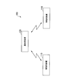
- FIG. 1 is a schematic block diagram illustrating a configuration of a wireless communication system 100 according to the present embodiment.
- the wireless communication system 100 includes a plurality of mobile station devices 110 (communication devices) and a base station device 120 that communicates with these mobile station devices 110.
- the base station apparatus 120 assigns to each mobile station apparatus 110 a subcarrier frequency band used for uplink transmission.
- Each of the mobile station apparatuses 110 arranges and transmits a signal on a subcarrier in a frequency band assigned by the base station apparatus 120.
- the wireless communication system 100 in this embodiment uses single carrier frequency division multiple access (SC-FDMA) for the uplink.
- SC-FDMA single carrier frequency division multiple access
- the mobile station apparatus 110 performs time-frequency conversion on the transmission signal by DFT to generate a frequency signal (also referred to as a frequency domain signal). Then, the mobile station apparatus 110 arranges and transmits the signal in the frequency domain on the subcarrier in the frequency band assigned by the base station apparatus 120.
- DFT is used as time-frequency conversion, but Fast Fourier Transform (FFT) may be used.
- the transform may be any orthogonal transform that may limit the number of points, such as the limit of the number of points according to the equation (1) for DFT. For example, a power of 2 is generally used. Frequency spreading using a Walsh sequence (Hadamard transform) may be applied.
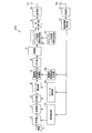
- FIG. 2 is a schematic block diagram illustrating a configuration of the mobile station apparatus 110.
- the mobile station apparatus 110 includes a coding unit 1, a modulation unit 2, a DFT unit 3, a resource allocation unit 4, a demodulation reference signal multiplexing unit 5, an IFFT unit 6, a switching unit 7, a sounding reference signal multiplexing unit 8, and a CP insertion unit 9.
- a transmission unit 10 a transmission antenna 11, a reception unit 12, a control information detection unit 13, an MCS identification unit 14, a resource identification unit 15, a demodulation reference signal generation unit 16, a sounding reference signal generation unit 17, and a reception antenna 18.
- the receiving antenna 18 receives a signal transmitted from the base station apparatus 120.
- the receiving unit 12 performs down conversion and A / D (Analog to Digital) conversion on the signal received by the receiving antenna 18 to generate digital data.
- the control signal detector 13 extracts control information from this digital data. For example, in LTE or LTE-A, this control information is transmitted on a control channel called PDCCH (Physical Downlink Control Channel), and is a control bit used for transmission control called DCI (Downlink Control Information) format.
- the control information may be any control information used for transmission control, and is not limited to LTE or LTE-A control information.
- the DCI format used for uplink transmission control is defined as DCI format 0 or DCI format 4, and the control signal detector 13 detects them. In this way, the control signal detection unit 13 detects control bits used for uplink transmission control.
- the mobile station apparatus 110 transmits transmission data according to this control bit.
- the control signal detection unit 13 notifies the MCS identification unit 14 of the transport block size (number of information bits), the coding rate, and the modulation scheme indicated by the detected control bits. In addition, the control signal detection unit 13 notifies the resource identification unit 15 of the number of DFT points and the resource index indicated by the detected control bits.
- the number of DFT points is the number of modulation symbols when performing DFT.
- the resource index is also called frequency band allocation information and represents a frequency position (subcarrier) where a frequency signal is arranged. In the present embodiment, a continuous frequency band is assigned to each mobile station apparatus 110. Therefore, the frequency band allocation information includes, for example, an index indicating the low frequency end of the allocated frequency band and an index indicating the bandwidth of the frequency band.
- the control information does not include the number of DFT points, and the control signal detection unit 13 may calculate the number of DFT points from the resource index included in the control information. For example, the number of subcarriers included in the frequency band indicated by the resource index is set as the number of DFT points. Further, the control signal detection unit 13 notifies the demodulation signal reference signal generation unit 16 of the pattern of the demodulation reference signal (DMRS: DeModulation Reference Signal) indicated by the detected control bit.
- DMRS DeModulation Reference Signal
- the pattern of the demodulation reference signal is information specifying a code sequence used as the demodulation reference signal, for example.
- the MCS identification unit 14 notifies the encoding unit 1 of the transport block size and the coding rate notified from the control signal detection unit 13. Further, the MCS identification unit 14 notifies the modulation unit 2 of the modulation scheme notified from the control signal detection unit 13.
- the resource identification unit 15 notifies the DFT unit 3 of the number of DFT points notified from the control signal detection unit 13. Further, the resource identification unit 15 notifies the resource allocation unit 4 of the resource index notified from the control signal detection unit 13.
- the demodulation reference signal generation unit 16 generates a demodulation reference signal (DMRS) having a pattern notified from the control signal detection unit 13 and outputs the demodulation reference signal (DMRS) to the demodulation reference signal multiplexing unit 5.
- DMRS demodulation reference signal
- the encoding unit 1 divides the input information bits Tx for each number of bits of the notified transport block size.
- the encoding unit 1 performs error correction encoding on the divided information bits Tx at the notified encoding rate to generate encoded bits.
- the modulation unit 2 modulates coded bits in accordance with the notified modulation method, and performs modulation such as quadrature phase shift keying (QPSK) and 16-ary quadrature amplitude modulation (16QAM). Generate a signal.
- the DFT unit 3 performs time-frequency conversion on the notified modulated signal having the number of DFT points to generate a frequency signal. This time-frequency conversion is performed by DFT.
- the number of DFT points of the DFT that can be executed by the DFT unit 3 is a number (predetermined number) including only 2, 3, and 5 as prime factors. That is, the number of DFT points must be Nsc satisfying the equation (1).
- the resource allocation unit 4 arranges the frequency signal at the frequency position designated by the notified resource index.
- the demodulation reference signal multiplexing unit 5 time-multiplexes DMRS on the signal in which the frequency signal is arranged at each frequency position by the resource allocation unit 4. Note that the frequency position at which the DMRS is multiplexed is the same as the frequency position at which the resource allocation unit 4 arranges the frequency signal.
- the MMRS may be multiplexed so as to be used at the time of demodulation (signal detection) on the receiving side, and the frequency position and multiplexing method (time multiplexing, frequency multiplexing, etc.) for multiplexing DMRS are not limited to this.
- the IFFT unit 6 performs IFFT (Inverse Fast Fourier Transform) on the signal multiplexed with DMRS to generate a time signal (also referred to as a time domain signal). This IFFT is performed with the number of FFT points (system band) defined in the wireless communication system 100.
- IFFT Inverse Fast Fourier Transform
- the switching unit 7 determines whether or not the subframe for transmitting the time domain signal generated by the IFFT unit 6 is a subframe for transmitting a sounding reference signal (SRS).
- the subframe is a minimum unit in the time direction when resources are allocated to the mobile station apparatus 110, and is configured by time-multiplexing a predetermined number of DFT blocks. Also. Also called a frame or a packet.
- the SRS is a reference signal for measuring (sounding) the propagation path state in the base station apparatus 120. This propagation path state is used when determining the allocation of the frequency band to each mobile station device 110 as will be described later.
- the switching unit 7 When it is determined that the subframe is an SRS transmission frame, the switching unit 7 outputs the time domain signal generated by the IFFT unit 6 to the sounding reference signal multiplexing unit 8. On the other hand, when determining that the subframe is not a subframe for transmitting SRS, the switching unit 7 outputs a time domain signal to the CP insertion unit 9 without doing anything.
- the sounding reference signal generation unit 17 generates an SRS.
- the sounding reference signal multiplexing unit 8 time-multiplexes the time domain signal input from the switching unit 7 and the SRS and outputs the result to the CP insertion unit 9.
- the CP insertion unit 9 inserts a cyclic prefix (CP) into the time domain signal input from the sounding reference signal multiplexing unit 8 or the switching unit 7.
- CP cyclic prefix
- the CP is a copy of the rear part of the time domain signal by a predefined length.
- the CP insertion unit 9 inserts the CP by inserting the CP at the head of the time domain signal.
- the transmission unit 10 performs transmission processing such as D / A (Digital to Analog) conversion, up-conversion, and amplification on the time domain signal in which the CP is inserted, and then transmits the signal from the transmission antenna 11 to the base station apparatus 120. To do.
- FIG. 3 is a schematic block diagram showing the configuration of base station apparatus 120.
- the base station apparatus 120 includes a receiving antenna 21, a receiving unit 22, a CP removing unit 23, a switching unit 24, a sounding reference signal separating unit 25, a propagation path sounding unit 26, a scheduling unit 27, a control signal generating unit 28, a transmitting unit 29, An FFT unit 30, a demodulation reference signal separation unit 31, a propagation path estimation unit 32, a resource separation unit 33, a signal detection unit 34, and a transmission antenna 35 are configured.
- the demodulation reference signal separation unit 31, the propagation path estimation unit 32, the resource separation unit 33, and the signal detection unit 34 are provided in the same number as the number of the mobile station devices 110 constituting the wireless communication system 100,
- the signal of the mobile station device 110 may be a detection target.
- the demodulation reference signal separation unit 31, the propagation path estimation unit 32, the resource separation unit 33, and the signal detection unit 34 may be provided one by one. In this case, each of these units repeatedly operates the same number of times as the number of mobile station apparatuses 110, and the signal of any mobile station apparatus 110 is set as a detection target at each repetition.
- the receiving antenna 21 receives a signal transmitted from the mobile station apparatus 110.
- the receiving unit 22 performs a receiving process such as down-conversion or A / D conversion on the signal received by the receiving antenna 21 to obtain a digital signal.
- the CP removing unit 23 removes a cyclic prefix (CP) from this digital signal.
- the switching unit 24 determines whether the subframe including the signal from which the CP is removed is a subframe in which the sounding reference signal (SRS) is multiplexed. Here, when it is determined that the subframe is not a multiplexed SRS, the switching unit 24 outputs the signal from which the CP has been removed to the FFT unit 30 as it is.
- SRS sounding reference signal
- the switching unit 24 when determining that the SRS is a multiplexed subframe, the switching unit 24 outputs the signal from which the CP has been removed to the sounding reference signal separation unit 25 as it is.
- the sounding reference signal separation unit 25 separates the SRS from the signal from which the CP has been removed.
- the sounding reference signal separation unit 25 outputs the separated SRS to the propagation path sounding unit 26 and outputs the remaining signals to the FFT unit 30.
- the propagation path sounding unit 26 calculates the propagation path state of the frequency at which the SRS is arranged from the SRS separated by the sounding reference signal separation unit 25. Since each mobile station apparatus 110 transmits SRS, the propagation path sounding unit 26 calculates the propagation path state for each mobile station apparatus 110.
- the propagation path state is calculated in units of resource blocks (12 subcarriers), but may be calculated in other transmission control units such as subcarriers.
- the propagation path state is, for example, a reception SINR (Signal to Interference plus Noise power Ratio) or a communication path capacity (transmission path capacity).
- the scheduling unit 27 determines the frequency band and the number of DFT points to be assigned to each mobile station device 110 based on the propagation path state calculated by the propagation path sounding unit 26.
- the scheduling unit 27 also determines a coding rate and a modulation scheme for each mobile station apparatus 110 in addition to frequency band allocation.
- the scheduling unit 27 outputs the determined information to the control signal generation unit 28. The frequency allocation method by the scheduling unit 27 will be described later.
- the control signal generation unit 28 generates control information for each of the mobile station apparatuses 110 based on the information input from the scheduling unit 27, and generates a control signal representing the control information.
- This control information includes a resource index indicating a frequency band allocation result, information indicating the number of DFT points, information indicating a coding rate, and information indicating a modulation scheme.
- the transmission unit 29 performs wireless transmission processing such as up-conversion and D / A conversion on the control signal, and then transmits the control signal to each mobile station apparatus 110 from the transmission antenna 35.
- the FFT unit 30 performs time-frequency conversion on the signal input from the switching unit 24 or the sounding reference signal separation unit 25 by fast Fourier transform to generate a frequency signal.
- the demodulation reference signal separation unit 31 separates DMRS from this frequency signal.
- the demodulation reference signal separation unit 31 outputs the separated DMRS to the propagation path estimation unit 32 and outputs the remaining frequency signals to the resource separation unit 33.
- the propagation path estimation unit 32 estimates the propagation path characteristics of the subcarrier (discrete frequency) used by each mobile station apparatus 110 for transmission and noise power including interference from other cells, and detects the obtained result as a signal. To the unit 34.
- the resource separation unit 33 extracts only the signal in the frequency band used by the mobile station device 110 to be detected from the frequency signal input from the demodulation reference signal separation unit 31.
- the frequency band used by the mobile station apparatus 110 is a frequency band assigned to the mobile station apparatus 110 by the scheduling unit 27. Therefore, the resource separation unit 33 acquires the information from the scheduling unit 27.
- the signal detection unit 34 performs signal detection, such as equalization, modulation symbol demodulation, and error correction decoding, on the signal extracted by the resource separation unit 33, and the information bit Tx input to the detection target mobile station apparatus 110.
- the decoded bit Rx corresponding to is obtained.
- the frequency bands assigned to each mobile station apparatus 110 may overlap between the mobile station apparatuses 110.
- separates the signal from the mobile station apparatus 110 of a detection target from the frequency signal of the overlapping frequency band is also included.
- This separation processing may be realized by interference cancellation by nonlinear iterative equalization (turbo equalization) based on the turbo principle, or ranking such as SIC (Successive Interference Cancellation) and serially of each mobile station apparatus 110. You may implement
- FIG. 4 is a schematic block diagram showing the configuration of the scheduling unit 27 in the present embodiment.
- the scheduling unit 27 includes a priority calculation unit 41, a resource determination unit 42, an RB adjustment unit 43, and a mobile station apparatus selection unit 44.
- the priority calculation unit 41 calculates the priority of each mobile station device 110 in each resource block based on the propagation path state of each resource block of each mobile station device 110 input from the sounding unit 26.
- the priority calculation unit 41 calculates this priority by, for example, the Max CIR method that prioritizes the received SINR of each mobile station device 110, the PF (Proportional Fairness) method that calculates the priority by Expression (2), and the like. To do.
- Equation (2) P (u, m) is the priority of the mth resource block of the uth mobile station apparatus 110. The larger this value, the higher the priority of this resource block.
- R (u, m) is the expected throughput when the m-th resource block is allocated to the u-th mobile station apparatus 110, and Rave (u) is the scheduling timing of the u-th mobile station apparatus 110. Represents the average throughput achieved.
- the resource determination unit 42 (allocation determination unit) allocates each resource block (frequency band) to the mobile station apparatus 110 with the highest priority in the resource block. That is, the resource determination unit 42 assigns a frequency band to each mobile station device 110. However, the resource determination unit 42 satisfies the condition A in which resource blocks continuous in the frequency direction are allocated to each mobile station apparatus 110 and the condition B in which a plurality of mobile station apparatuses 110 are not allocated to each resource block. Make this assignment. Note that, in the uplink of this embodiment, the single carrier frequency division multiple access scheme is used, and therefore the allocation result is allocated so as to satisfy the condition A.
- the resource determination unit 42 searches for an assignment that satisfies the above-described conditions A and B in order from the mobile station apparatus 110 with the lowest average throughput and has the highest total priority of the resource blocks of the assignment result, thereby assigning the assignment.
- the number of resource blocks allocated to each mobile station apparatus 110 may be a predetermined number, a number requested by each mobile station apparatus 110, or determined according to QoS (Quality of Service). It may be a number.
- Mobile station device selection unit 44 receives the result of allocation by the resource determination unit 42. The mobile station device selection unit 44 determines the number of DFT points indicated by the allocation result for each mobile station device 110.
- the mobile station apparatus selection unit 44 determines that the number of DFT points indicated by the allocation result (the number of subcarriers is the same) for each mobile station apparatus 110 is 2. It is determined whether the number is a number (predetermined number) that is a prime factor only of 3, 5, 5. The mobile station apparatus selection unit 44 determines that the number of DFT points satisfies Expression (1) 110.
- the result of allocation by the resource determination unit 42 is output as it is as the final frequency band allocation result, while the mobile station apparatus selection unit 44 determines that the number of DFT points is an expression 1) (for the mobile station apparatus 110 that has determined that the number of resource blocks corresponding to the number of DFT points that do not satisfy Expression (1) is referred to as “number of resource blocks that cannot be allocated” hereinafter)
- the result of allocation by the determination unit 42 is output to the RB adjustment unit 43.
- the RB adjustment unit 43 (frequency band adjustment unit) changes the allocation result input from the mobile station apparatus selection unit 44 so as to satisfy Expression (1). More specifically, the RB adjustment unit 43 increases the allocated resource blocks.
- the RB adjustment unit 43 allows overlapping of resource blocks to be allocated between the mobile station apparatus 110 to be allocated and other mobile station apparatuses 110. Then, the RB adjustment unit 43 outputs the increased result as the final frequency band allocation result. Specifically, the RB adjustment unit 43 adds one of the resource blocks adjacent to the resource block group as a result of assignment until the assignment result satisfies Expression (1). As for which of the two ends to add, for example, the higher priority may be selected, or the one not assigned to another mobile station apparatus 110 may be selected.
- the number of resource blocks to be increased is minimized is shown here, when it is determined that the signal can be separated by the reception process or when it is determined that the throughput is increased as a result, Further, the number of RBs may be increased.
- FIG. 5 is a flowchart for explaining the operation of the scheduling unit 27 in the present embodiment.
- the priority calculation unit 41 calculates a priority for each combination of a resource block (RB) and the mobile station apparatus 110.
- the resource determination unit 42 assigns an RB to each mobile station apparatus 110 based on the priority.
- the mobile station apparatus selection unit 44 assigns a virtual serial number (may be an ID) to each mobile station apparatus 110.
- step S5 the mobile station apparatus selection unit 44 determines whether or not the allocation result in step S2 for the mobile station apparatus 110 with the number u is the number of RBs that cannot be allocated.
- the process proceeds to step S6.
- step S6 the RB adjustment unit 43 increases the RB until the number of RBs that can be allocated is reached.
- step S7 the RB adjustment unit 43 confirms the assignment. That is, the RB adjustment unit 43 sets the result of the allocation so far as the final frequency band allocation result, and proceeds to step S9.
- step S5 when it is determined in step S5 that the number of RBs cannot be allocated (S5-No), the process directly proceeds to step S7 described above.
- step S9 it is determined whether or not the u-th mobile station apparatus 110 is the last-numbered mobile station apparatus 110. If it is determined that the mobile station apparatus 110 is the last number (S9-Yes), the allocation is terminated. On the other hand, when it is determined that the mobile station apparatus 110 is not the last number (S9-No), the process proceeds to step S8.
- step S8 the mobile station apparatus selection unit 44 adds 1 to the serial number u, sets the serial number u to the number of the mobile station apparatus 110 whose assignment has not been determined, and returns to step S5. In this way, by repeating Step S5 and subsequent steps up to the last-numbered mobile station apparatus 110, the allocation of frequency bands for all mobile station apparatuses 110 is confirmed.
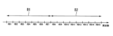
- FIG. 6 is a diagram illustrating an example of an allocation result by the resource determination unit 42.
- the horizontal axis represents frequency.
- symbols RB1, RB2,... RB15 are resource blocks.
- the resource determination unit 42 assigns a frequency band (resource blocks RB1 to RB7) denoted by reference symbol B1 to the first mobile station device 110, and assigns a reference symbol B2 to the second mobile station device 110.
- are assigned frequency bands (resource blocks RB8 to RB15). Since the frequency band B1 is 7 resource blocks, the corresponding number of DFT points is 7 ⁇ 12 84.
- the prime factors of 84 are 2, 3, and 7, and do not satisfy Expression (1).
- the prime factors of 96 are only 2 and 3, which satisfy the formula (1).
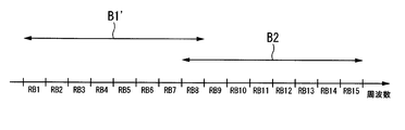
- FIG. 7 is a diagram illustrating an example of an allocation result by the scheduling unit 27 in the present embodiment.
- the horizontal axis represents frequency.
- the allocation result in FIG. 7 is an example of the allocation result by the scheduling unit 27 when the resource determination unit 42 performs the allocation shown in FIG.
- the RB adjustment unit 43 uses the frequency band B1 ′ obtained by adding the resource block RB8 to the frequency band B1 as the first mobile station apparatus 110 by the scheduling unit 27.
- the mobile station apparatus selection unit 44 uses the frequency band B2 that is the allocation result by the resource determination unit 42 as it is as the second mobile station apparatus by the scheduling unit 27. 110 is assigned to 110.
- FIG. 8 is a diagram illustrating an example of a conventional assignment result.
- the example of FIG. 8 is a conventional assignment result in the same situation as when the resource determination unit 42 assigns as shown in FIG.
- the conventional method such as Non-Patent Document 1
- SC-FDMA SC-FDMA
- allocation is performed so as to satisfy Expression (1). Therefore, the frequency band B2 is allocated to the second mobile station apparatus as in FIG. 7, but the resource blocks RB1 to RB6 are excluded from the frequency band B1 except for the resource block B7.
- the frequency band B1 ′′ is assigned.
- the frequency band B1 ′ is assigned to the first mobile station apparatus 110 to avoid the limitation on the number of RBs (number of DFT points).
- non-orthogonal multiplexing in which the allocated frequency band of the first mobile station device 110 and the allocated frequency band of the second mobile station device 110 overlap (non-orthogonal in the sense of a radio resource sharing method). May be called access).
- This may be called orthogonal multiplexing if there are two or more receiving antennas, and may be called orthogonal multiplexing.
- intentionally performing partial overlap here is called non-orthogonal multiplexing.
- each mobile station apparatus 110 can use the resource blocks to be allocated while avoiding the number of resource blocks that cannot be allocated, and as a result, the frequency utilization efficiency is increased. That is, even if the number of DFT points is limited, it is possible to suppress a decrease in frequency band utilization efficiency. Further, for example, as shown in FIG. 7, the total number of RBs is 15 while the number of RBs allocated to the first and second mobile station apparatuses is 8 respectively. It is equivalent to using it. Therefore, since a large number of radio resources can be allocated in some resource blocks, the utilization efficiency of radio resources is high.
- the base station device 120 allocates a frequency band to the mobile station device 110.
- the RB adjustment unit 43 of the mobile station apparatus 110 uses The number of resource blocks to be used may be increased so that the number of resource blocks to be used does not become an unassignable resource block number.
- the reception quality may be used when the reception quality can be grasped, or may be based on a predetermined rule.
- a method of increasing the number of high-frequency component resource blocks to the minimum number of resource blocks that cannot be allocated exceeding the allocated number of resource blocks can be considered, but any rule may be used as long as it can be uniquely recognized.
- the base station apparatus 120 that performs reception processing may receive the signals of a plurality of mobile station apparatuses 110 in an overlapping manner. Also, in this case, since the base station apparatus 120 receives the received resource blocks with a number of resource blocks different from the notified number of resource blocks, it may be determined in advance to notify the increased resource block index from the mobile station apparatus 110 side. Alternatively, a method may be used in which signal processing is attempted a plurality of times for all resource block candidates increased in signal detection, and the detection result having the best reception performance is used.
- Clustered DFT-S-OFDMA without restriction on the number of divisions (number of clusters) is used for the uplink.
- the number of divisions is the number of frequency band divisions allocated to the mobile station apparatus 110.
- the division number is zero.
- Clustered DFT-S-OFDMA is another example of SC-FDMA in which a transmission signal is subjected to time-frequency conversion by DFT, and transmitted on subcarriers.
- the configurations of the wireless communication system 100, the mobile station apparatus 110, and the base station apparatus 120 in the present embodiment are the same as those in FIGS. However, the operation of the resource determination unit 42 of the base station device 120 is different from that of the first embodiment.
- the resource determination unit 42 is configured to satisfy the condition A that the resource block continuous in the frequency direction is allocated to the mobile station device 110 when the frequency band is allocated.
- the resource determination unit 42 in the present embodiment performs frequency band allocation without being restricted by the condition A described above.
- FIG. 9 is a diagram illustrating an example of an allocation result by the resource determination unit 42 in the present embodiment.
- the horizontal axis represents frequency.
- symbols RB1, RB2,... RB15 are resource blocks.
- the resource determination unit 42 assigns the frequency band (resource blocks RB1 to RB3, RB7, RB9, RB13 to RB15) to which the first mobile station apparatus 110 is assigned a code B11.
- the prime factors of 96 are only 2 and 3, which satisfy the formula (1).
- the prime factors of 84 are 2, 3, and 7, and do not satisfy Expression (1).
- FIG. 10 is a diagram illustrating an example of an assignment result by the scheduling unit 27 in the present embodiment.
- the horizontal axis represents frequency.
- the mobile station apparatus selection unit 44 uses the frequency band B11 that is the allocation result by the resource determination unit 42 as it is as the first mobile station apparatus by the scheduling unit 27. 110 is assigned to 110.
- FIG. 11 is a diagram showing an example of a conventional assignment result.
- the example of FIG. 11 shows a conventional allocation result in the same situation as when the resource determination unit 42 allocates as shown in FIG.
- a conventional method such as Non-Patent Document 1
- Clustered DFT-S-OFDM with no restriction on the number of divisions is used, in addition to the above-described condition B, assignment is performed so as to satisfy Expression (1). Therefore, the frequency band B11 is allocated to the first mobile station apparatus as in FIG. 10, but the resource blocks RB4 to RB6 except for the resource block B8 from the frequency band B12 are allocated to the second mobile station apparatus.
- a frequency band B12 ′′ composed of RB10 to RB12 is allocated.
- each mobile station apparatus 110 can use the resource blocks to be allocated while avoiding the number of resource blocks that cannot be allocated. Increases efficiency.
- the RB adjustment unit 43 may select the resource blocks to be added in order from the highest priority value among the assignable frequency bands, or the overlapping RBs. You may make it select on conditions that it is easy to isolate
- the configurations of the wireless communication system 100, the mobile station apparatus 110, and the base station apparatus 120 in the present embodiment are the same as those in FIGS. 1, 2, 3, and 4, and thus the description thereof is omitted.
- the operation of the resource determination unit 42 of the base station device 120 is different from those in the first and second embodiments.
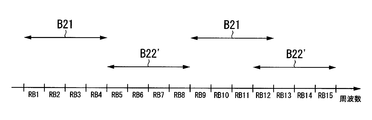
- the resource determination unit 42 satisfies the condition A ′ that allows the resource block group to be allocated to the mobile station device 110 to be divided into two, instead of the above-described condition A when assigning the frequency band. Like that.
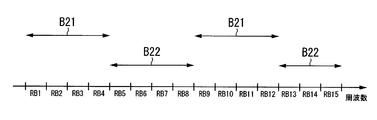
- FIG. 12 is a diagram illustrating an example of an allocation result by the resource determination unit 42 in the present embodiment.
- the horizontal axis represents frequency.
- symbols RB1, RB2,... RB15 are resource blocks.
- the resource determination unit 42 assigns frequency bands (resource blocks RB1 to RB4, RB9 to RB12) denoted by reference symbol B21 to the first mobile station apparatus 110.
- the prime factors of 96 are only 2 and 3, which satisfy the formula (1).
- the prime factors of 84 are 2, 3, and 7, and do not satisfy Expression (1).
- FIG. 13 is a diagram illustrating an example of an allocation result by the scheduling unit 27 in the present embodiment.
- the horizontal axis represents frequency.
- the allocation result of FIG. 13 is an example of the allocation result by the scheduling unit 27 when the resource determination unit 42 performs the allocation shown in FIG. Since the frequency band B22 of FIG. 12 does not satisfy Expression (1), the RB adjustment unit 43 adds any resource block to the frequency band B22. Since the resource block to be added is adjacent to either end of the already allocated resource block group, in the case of FIG. 12, RBs that can be added are ⁇ RB4, RB9, RB12 ⁇ . This is defined as an assignable RB.
- the RB adjustment unit 43 selects and adds the highest priority among these RBs that can be allocated. Specifically, assuming that a set of RBs that can be allocated is S and an index of the mobile station apparatus having the number of resource blocks that cannot be allocated is u ′, an RB to be allocated is determined by the following equation.
- RB of index m determined by Equation (3) is assigned to u′-th mobile station apparatus 110.
- the RB included in the set S is RB8 in the first mobile station apparatus 110, and in the case of the second embodiment, all RBs are included because the number of clusters is infinite.
- the RB increased in equation (3) is reassembled as an allocation resource. It can be applied in any case by defining S, further increasing the number of allocated resources by Equation (3), and repeating this process until the number of resource blocks that cannot be allocated is reached.
- the mobile station apparatus selection unit 44 uses the frequency band B21, which is the allocation result by the resource determination unit 42, as it is as the first mobile station apparatus by the scheduling unit 27. 110 is assigned to 110.
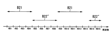
- FIG. 14 is a diagram showing an example of a conventional assignment result.
- the example of FIG. 14 shows a conventional allocation result in the same situation as when the resource determination unit 42 allocates as shown in FIG.
- a conventional method such as Non-Patent Document 1
- the assignment is performed so as to satisfy Expression (1). Therefore, the frequency band B21 is allocated to the first mobile station apparatus as in FIG. 12, but the resource blocks RB4 to RB6, except for the resource block B13 from the frequency band B22, are allocated to the second mobile station apparatus.
- a frequency band B22 ′′ composed of RB14 to RB15 is allocated.
- each mobile station apparatus 110 can use the resource blocks to be allocated while avoiding the number of resource blocks that cannot be allocated. That is, even if the number of DFT points is limited, it is possible to suppress a decrease in frequency band utilization efficiency. Furthermore, since it is equivalent to allocating many radio resources in some RBs, the utilization efficiency of radio resources is high.
- a program for realizing part or all of the functions of mobile station apparatus 110 and base station apparatus 120 in each of the above-described embodiments is recorded on a computer-readable recording medium, and recorded on this recording medium.
- the mobile station apparatus 110 and the base station apparatus 120 may be realized by causing a computer system to read and execute the program.
- the “computer system” includes an OS and hardware such as peripheral devices.
- the “computer-readable recording medium” refers to a storage device such as a flexible medium, a magneto-optical disk, a portable medium such as a ROM or a CD-ROM, and a hard disk incorporated in a computer system. Furthermore, the “computer-readable recording medium” dynamically holds a program for a short time like a communication line when transmitting a program via a network such as the Internet or a communication line such as a telephone line. In this case, a volatile memory in a computer system serving as a server or a client in that case, and a program that holds a program for a certain period of time are also included.
- the program may be a program for realizing a part of the functions described above, and may be a program capable of realizing the functions described above in combination with a program already recorded in a computer system.
- Each functional block of the mobile station apparatus 110 and the base station apparatus 120 may be individually chipped, or a part or all of them may be integrated into a chip.
- the method of circuit integration is not limited to LSI, and may be realized by a dedicated circuit or a general-purpose processor.
- an integrated circuit based on the technology can also be used.
- the present invention is suitable for use in a mobile communication system in which a mobile phone device is a mobile station device, but is not limited thereto.
- Propagation path sounding part 27 ... Scheduling part 28 ... Control signal generation part 29 ... Transmission part 30 ... FFT part 31 . Reference signal separation part for demodulation 32 . Propagation path estimation unit 33 ... Resource separation unit 34 ... Signal detection unit 35 ... Transmission antenna 41 . Priority calculation unit 42 ... Resource decision Fixed unit 43 ... RB adjustment unit 44 ... mobile station apparatus selection unit 100 ... wireless communication system 110 ... mobile station apparatus 120 ... base station apparatus
Landscapes
- Engineering & Computer Science (AREA)
- Signal Processing (AREA)
- Computer Networks & Wireless Communication (AREA)
- Mobile Radio Communication Systems (AREA)
- Digital Transmission Methods That Use Modulated Carrier Waves (AREA)
Abstract
直交変換する際のポイント数に制約があっても、周波数帯域の利用効率の低下を抑えることができること。 送信信号を直交変換し、サブキャリアに配置して送信する複数の通信装置の各々に、サブキャリアの周波数帯域を割り当てる割り当て決定部と、複数の通信装置のうち、割当て決定部が割り当てた周波数帯域に含まれるサブキャリアの数が、所定の数ではない通信装置を選択する通信装置選択部と、選択した通信装置の各々に割り当てる周波数帯域を、割当て決定部が割り当てた周波数帯域から変更する周波数帯域調整部とを具備し、周波数帯域調整部は、変更の結果の周波数帯域の各々に含まれるサブキャリアの数が、前述の所定の数となるように、変更を行うことを特徴とする基地局装置。
Description
本発明は、基地局装置、無線通信システム、無線通信装置、周波数帯域割り当て方法およびプログラムに関する。
第3.9世代の携帯電話の無線通信システムであるLTE(Long Term Evolution)システムの標準化が完了し、最近ではLTEシステムをより発展させたLTE-A(LTE-Advanced)が、第4世代の無線通信システム(IMT-Aなどとも称する)の一つとして標準化が行われている。
これらのシステムの上りリンク(移動局から基地局への回線)のアクセス方式としては、シングルキャリア周波数分割多元接続方式(SC-FDMA:Single Carrier Frequency Division Multiple Access)とClustered DFT-S-OFDMA(DFT Spread Orthogonal Frequency Division Multiple Access)の2つが採用されている。SC-FDMAは、DFT(Discrete Fourier Transform;離散フーリエ変換)により時間信号を周波数信号に時間周波数変換し、得られた周波数信号をシステム帯域内の任意の周波数に連続して配置する方式であり、DFT-S-OFDMなどとも称される。一方、Clustered DFT-S-OFDMAでは、SC-FDMAと同様にして得られた周波数信号を複数のクラスタと呼ばれる部分スペクトルに分割し、各クラスタをシステム帯域内の任意の周波数に不連続に配置することができる。なお、LTE-Aでは最大のクラスタ数は2であるが、クラスタ数は任意の数に設定することができる。
ここで、LTEやLTE-Aでは、DFTの演算量を削減するために、高速フーリエ変換(FFT:Fast Fourier Transform)の考え方に基づいてバタフライ演算で使用するDFTポイント数に制限を設けている。具体的には、各移動局装置が使用可能なDFTポイント数は、リソースブロックに含まれるサブキャリア数の整数倍で、かつ式(1)を満たすものに限定される(非特許文献1)。

ここで、NscはDFTポイント数(帯域幅と同一であるため、サブキャリア数や離散周波数のポイント数ともいえる。)であり、α、β、γはゼロ以上の整数を表す。式(1)は、DFTを実現するバタフライ演算を構成するDFTポイント数が2と3と5のみでよいことを意味している。これにより、送信処理に係る演算量および回路規模を削減することができる。
3GPP、"Evolved Universal Terrestrial Radio Access(E-UTRA);Physical channels and modulation"、TS36.211 v10.2.0
しかしながら、上述の非特許文献1においては、DFTポイント数の制約により、移動局装置に割り当てる周波数帯域幅に制約が生じるために、周波数帯域の利用効率が低下することがあるという問題がある。例えば、未割り当ての周波数帯域として、7RB(Resource Block;リソースブロック、非特許文献1では1RBは12サブキャリアである)があっても、ある移動局装置に割り当てることができる周波数帯域は、式(1)を満たさなければならないために6RBとなってしまい、周波数帯域の利用効率が低くなってしまう。
本発明は、このような事情に鑑みてなされたもので、その目的は、直交変換する際のポイント数に制約があっても、周波数帯域の利用効率の低下を抑えることができる基地局装置、無線通信システム、無線通信装置、周波数帯域割り当て方法およびプログラムを提供することにある。
(1)この発明は上述した課題を解決するためになされたもので、本発明の一態様は、送信信号を直交変換し、サブキャリアに配置して送信する複数の通信装置の各々に、前記サブキャリアの周波数帯域を割り当てる割り当て決定部と、前記複数の通信装置のうち、前記割当て決定部が割り当てた周波数帯域に含まれるサブキャリアの数が、所定の数ではない前記通信装置を選択する通信装置選択部と、前記選択した通信装置の各々に割り当てる周波数帯域を、前記割当て決定部が割り当てた周波数帯域から変更する周波数帯域調整部とを具備し、前記周波数帯域調整部は、前記変更の結果の周波数帯域の各々に含まれるサブキャリアの数が、前記所定の数となるように、前記変更を行うことを特徴とする基地局装置である。
(2)また、本発明の他の態様は、上述の基地局装置であって、前記割り当て決定部は、前記複数の通信装置の間で、割り当てられる周波数帯域が重複しないように、前記周波数帯域の割り当てを行い、前記周波数帯域調整部は、前記選択した通信装置と他の前記通信装置との間で、割り当てられる周波数帯域の重複を許容し、かつ、前記割り当て決定部が割り当てた周波数帯域に対して周波数帯域を追加することで、前記変更を行うことを特徴とする。
(3)また、本発明の他の態様は、上述の基地局装置であって、前記周波数帯域調整部は、前記周波数帯域の追加を行う際、割り当て可能な周波数帯域のうち、優先度の高いものから順に追加することを特徴とする。
(4)また、本発明の他の態様は、上述の基地局装置であって、前記周波数帯域調整部が追加する周波数帯域は、前記割り当て決定部が割り当てた周波数帯域に隣接する周波数帯域であることを特徴とする。
(5)また、本発明の他の態様は、上述の基地局装置であって、前記複数の通信装置が送信した信号を受信する受信部と、前記受信した信号から前記通信装置各々の信号を検出する信号検出部とを具備し、前記信号検出部は、前記割り当てられた周波数帯域が他の前記通信装置と重複している前記通信装置の信号については、干渉キャンセリングを行って、前記受信した信号から分離することを特徴とする。
(6)また、本発明の他の態様は、上述の基地局装置であって、前記干渉キャンセリングは、ターボ原理に基づく非線形繰り返し等化またはシリアル干渉キャンセリングであることを特徴とする。
(7)また、本実施形態の他の態様は、上述の基地局装置であって、前記直交変換は、時間周波数変換であることを特徴とする。
(8)また、本発明の他の態様は、複数の通信装置と、基地局装置とを具備する無線通信システムであって、前記通信装置は、送信信号を直交変換し、サブキャリアに配置して送信する送信部を具備し、前記基地局装置は、前記通信装置の各々に、前記サブキャリアの周波数帯域を割り当てる割り当て決定部を具備し、前記基地局装置または前記通信装置は、前記割当て決定部が割り当てた周波数帯域に含まれるサブキャリアの数が、所定の数であるときは、前記割当て決定部が割り当てた周波数帯域を変更する周波数帯域調整部を具備し、前記周波数帯域調整部は、前記変更の結果の周波数帯域に含まれるサブキャリアの数が、前記所定の数とならないように、前記変更を行うことを特徴とする。
(9)また、本発明の他の態様は、送信信号を直交変換し、基地局装置が割り当てた周波数帯域のサブキャリアに、前記直交変換した信号を配置して送信する無線通信装置であって、前記基地局装置が割り当てた周波数帯域に含まれるサブキャリアの数が、所定の数であるときは、前記基地局装置が割り当てた周波数帯域を変更する周波数帯域調整部を具備し、前記周波数帯域調整部は、前記変更の結果の周波数帯域に含まれるサブキャリアの数が、前記所定の数とならないように、前記変更を行うことを特徴とする。
(10)また、本発明の他の態様は、基地局装置における周波数帯域割り当て方法であって、送信信号を直交変換し、サブキャリアに配置して送信する複数の通信装置の各々に、前記サブキャリアの周波数帯域を割り当てる第1の過程と、前記複数の通信装置のうち、前記第1の過程にて割り当てた周波数帯域に含まれるサブキャリアの数が、所定の数ではない前記通信装置を選択する第2の過程と、前記選択した通信装置の各々に割り当てる周波数帯域を、前記第1の過程が割り当てた周波数帯域から変更する第3の過程とを有し、前記第3の過程において、前記変更の結果の周波数帯域の各々に含まれるサブキャリアの数が、前記所定の数となるように、前記変更を行うことを特徴とする。
(11)また、本発明の他の態様は、送信信号を直交変換し、基地局装置が割り当てた周波数帯域のサブキャリアに、前記直交変換した信号を配置して送信する無線通信装置における周波数帯域割り当て方法であって、前記基地局装置が割り当てた周波数帯域に含まれるサブキャリアの数が、所定の数であるときは、前記基地局装置が割り当てた周波数帯域を変更する第1の過程を有し、前記第1の過程は、前記変更の結果の周波数帯域に含まれるサブキャリアの数が、前記所定の数とならないように、前記変更を行うことを特徴とする周波数帯域割り当て方法である。
(12)また、本発明の他の態様は、基地局装置のコンピュータを、送信信号を直交変換し、サブキャリアに配置して送信する複数の通信装置の各々に、前記サブキャリアの周波数帯域を割り当てる割り当て決定部、前記複数の通信装置のうち、前記割当て決定部が割り当てた周波数帯域に含まれるサブキャリアの数が、所定の数ではない前記通信装置を選択する通信装置選択部、前記選択した通信装置の各々に割り当てる周波数帯域を、前記割当て決定部が割り当てた周波数帯域から変更する周波数帯域調整部として機能させるためのプログラムであって、前記周波数帯域調整部は、前記変更の結果の周波数帯域の各々に含まれるサブキャリアの数が、前記所定の数となるように、前記変更を行うことを特徴とする。
(13)また、本発明の他の態様は、送信信号を直交変換し、基地局装置が割り当てた周波数帯域のサブキャリアに、前記直交変換した信号を配置して送信する無線通信装置のコンピュータを、前記基地局装置が割り当てた周波数帯域に含まれるサブキャリアの数が、所定の数であるときは、前記基地局装置が割り当てた周波数帯域を変更する周波数帯域調整部として機能させるためのプログラムであって、前記周波数帯域調整部は、前記変更の結果の周波数帯域に含まれるサブキャリアの数が、前記所定の数とならないように、前記変更を行うことを特徴とする。
(2)また、本発明の他の態様は、上述の基地局装置であって、前記割り当て決定部は、前記複数の通信装置の間で、割り当てられる周波数帯域が重複しないように、前記周波数帯域の割り当てを行い、前記周波数帯域調整部は、前記選択した通信装置と他の前記通信装置との間で、割り当てられる周波数帯域の重複を許容し、かつ、前記割り当て決定部が割り当てた周波数帯域に対して周波数帯域を追加することで、前記変更を行うことを特徴とする。
(3)また、本発明の他の態様は、上述の基地局装置であって、前記周波数帯域調整部は、前記周波数帯域の追加を行う際、割り当て可能な周波数帯域のうち、優先度の高いものから順に追加することを特徴とする。
(4)また、本発明の他の態様は、上述の基地局装置であって、前記周波数帯域調整部が追加する周波数帯域は、前記割り当て決定部が割り当てた周波数帯域に隣接する周波数帯域であることを特徴とする。
(5)また、本発明の他の態様は、上述の基地局装置であって、前記複数の通信装置が送信した信号を受信する受信部と、前記受信した信号から前記通信装置各々の信号を検出する信号検出部とを具備し、前記信号検出部は、前記割り当てられた周波数帯域が他の前記通信装置と重複している前記通信装置の信号については、干渉キャンセリングを行って、前記受信した信号から分離することを特徴とする。
(6)また、本発明の他の態様は、上述の基地局装置であって、前記干渉キャンセリングは、ターボ原理に基づく非線形繰り返し等化またはシリアル干渉キャンセリングであることを特徴とする。
(7)また、本実施形態の他の態様は、上述の基地局装置であって、前記直交変換は、時間周波数変換であることを特徴とする。
(8)また、本発明の他の態様は、複数の通信装置と、基地局装置とを具備する無線通信システムであって、前記通信装置は、送信信号を直交変換し、サブキャリアに配置して送信する送信部を具備し、前記基地局装置は、前記通信装置の各々に、前記サブキャリアの周波数帯域を割り当てる割り当て決定部を具備し、前記基地局装置または前記通信装置は、前記割当て決定部が割り当てた周波数帯域に含まれるサブキャリアの数が、所定の数であるときは、前記割当て決定部が割り当てた周波数帯域を変更する周波数帯域調整部を具備し、前記周波数帯域調整部は、前記変更の結果の周波数帯域に含まれるサブキャリアの数が、前記所定の数とならないように、前記変更を行うことを特徴とする。
(9)また、本発明の他の態様は、送信信号を直交変換し、基地局装置が割り当てた周波数帯域のサブキャリアに、前記直交変換した信号を配置して送信する無線通信装置であって、前記基地局装置が割り当てた周波数帯域に含まれるサブキャリアの数が、所定の数であるときは、前記基地局装置が割り当てた周波数帯域を変更する周波数帯域調整部を具備し、前記周波数帯域調整部は、前記変更の結果の周波数帯域に含まれるサブキャリアの数が、前記所定の数とならないように、前記変更を行うことを特徴とする。
(10)また、本発明の他の態様は、基地局装置における周波数帯域割り当て方法であって、送信信号を直交変換し、サブキャリアに配置して送信する複数の通信装置の各々に、前記サブキャリアの周波数帯域を割り当てる第1の過程と、前記複数の通信装置のうち、前記第1の過程にて割り当てた周波数帯域に含まれるサブキャリアの数が、所定の数ではない前記通信装置を選択する第2の過程と、前記選択した通信装置の各々に割り当てる周波数帯域を、前記第1の過程が割り当てた周波数帯域から変更する第3の過程とを有し、前記第3の過程において、前記変更の結果の周波数帯域の各々に含まれるサブキャリアの数が、前記所定の数となるように、前記変更を行うことを特徴とする。
(11)また、本発明の他の態様は、送信信号を直交変換し、基地局装置が割り当てた周波数帯域のサブキャリアに、前記直交変換した信号を配置して送信する無線通信装置における周波数帯域割り当て方法であって、前記基地局装置が割り当てた周波数帯域に含まれるサブキャリアの数が、所定の数であるときは、前記基地局装置が割り当てた周波数帯域を変更する第1の過程を有し、前記第1の過程は、前記変更の結果の周波数帯域に含まれるサブキャリアの数が、前記所定の数とならないように、前記変更を行うことを特徴とする周波数帯域割り当て方法である。
(12)また、本発明の他の態様は、基地局装置のコンピュータを、送信信号を直交変換し、サブキャリアに配置して送信する複数の通信装置の各々に、前記サブキャリアの周波数帯域を割り当てる割り当て決定部、前記複数の通信装置のうち、前記割当て決定部が割り当てた周波数帯域に含まれるサブキャリアの数が、所定の数ではない前記通信装置を選択する通信装置選択部、前記選択した通信装置の各々に割り当てる周波数帯域を、前記割当て決定部が割り当てた周波数帯域から変更する周波数帯域調整部として機能させるためのプログラムであって、前記周波数帯域調整部は、前記変更の結果の周波数帯域の各々に含まれるサブキャリアの数が、前記所定の数となるように、前記変更を行うことを特徴とする。
(13)また、本発明の他の態様は、送信信号を直交変換し、基地局装置が割り当てた周波数帯域のサブキャリアに、前記直交変換した信号を配置して送信する無線通信装置のコンピュータを、前記基地局装置が割り当てた周波数帯域に含まれるサブキャリアの数が、所定の数であるときは、前記基地局装置が割り当てた周波数帯域を変更する周波数帯域調整部として機能させるためのプログラムであって、前記周波数帯域調整部は、前記変更の結果の周波数帯域に含まれるサブキャリアの数が、前記所定の数とならないように、前記変更を行うことを特徴とする。
この発明によれば、直交変換する際のポイント数に制約があっても、周波数帯域の利用効率の低下を抑えることができる。
[第1の実施形態]
以下、図面を参照しながら、本発明の第1の実施形態について説明する。図1は、本実施形態における無線通信システム100の構成を示す概略ブロック図である。図1に示すように、無線通信システム100は、複数の移動局装置110(通信装置)と、これらの移動局装置110と通信する基地局装置120とを含んで構成される。基地局装置120は、各移動局装置110に対して、上りリンクの送信に用いるサブキャリアの周波数帯域を割り当てる。移動局装置110の各々は、基地局装置120が割り当てた周波数帯域のサブキャリアに、信号を配置して送信する。なお、本実施形態における無線通信システム100は、アップリンクにシングルキャリア周波数分割多元接続(SC-FDMA)を用いる。すなわち、移動局装置110は、送信信号をDFTにより時間周波数変換して、周波数信号(周波数領域の信号ともいう)を生成する。そして、移動局装置110は、基地局装置120が割り当てた周波数帯域のサブキャリアに、該周波数領域の信号を配置して送信する。なお、本実施形態では時間周波数変換としてDFTを使用しているが、高速フーリエ変換(FFT:Fast Fourie Transform)を使用するようにしてもよい。また、この変換は、DFTに対する式(1)によるポイント数の制限のように、ポイント数が制限される可能性のある直交変換であればよく、例えば、2のべき乗が一般的に使用されるウォルシュ系列(アダマール変換)を用いた周波数拡散などを適用してもよい。
以下、図面を参照しながら、本発明の第1の実施形態について説明する。図1は、本実施形態における無線通信システム100の構成を示す概略ブロック図である。図1に示すように、無線通信システム100は、複数の移動局装置110(通信装置)と、これらの移動局装置110と通信する基地局装置120とを含んで構成される。基地局装置120は、各移動局装置110に対して、上りリンクの送信に用いるサブキャリアの周波数帯域を割り当てる。移動局装置110の各々は、基地局装置120が割り当てた周波数帯域のサブキャリアに、信号を配置して送信する。なお、本実施形態における無線通信システム100は、アップリンクにシングルキャリア周波数分割多元接続(SC-FDMA)を用いる。すなわち、移動局装置110は、送信信号をDFTにより時間周波数変換して、周波数信号(周波数領域の信号ともいう)を生成する。そして、移動局装置110は、基地局装置120が割り当てた周波数帯域のサブキャリアに、該周波数領域の信号を配置して送信する。なお、本実施形態では時間周波数変換としてDFTを使用しているが、高速フーリエ変換(FFT:Fast Fourie Transform)を使用するようにしてもよい。また、この変換は、DFTに対する式(1)によるポイント数の制限のように、ポイント数が制限される可能性のある直交変換であればよく、例えば、2のべき乗が一般的に使用されるウォルシュ系列(アダマール変換)を用いた周波数拡散などを適用してもよい。
図2は、移動局装置110の構成を示す概略ブロック図である。移動局装置110は、符号部1、変調部2、DFT部3、リソース割当部4、復調用参照信号多重部5、IFFT部6、切替部7、サウンディング参照信号多重部8、CP挿入部9、送信部10、送信アンテナ11、受信部12、制御情報検出部13、MCS識別部14、リソース識別部15、復調用参照信号生成部16、サウンディング参照信号生成部17、受信アンテナ18を含んで構成される。
受信アンテナ18は、基地局装置120が送信した信号を受信する。受信部12は、受信アンテナ18が受信した信号に対して、ダウンコンバージョンおよびA/D(Analog to Digital)変換などを行い、ディジタルデータを生成する。制御信号検出部13は、このディジタルデータから制御情報を抽出する。この制御情報は、例えば、LTEやLTE-Aでは、PDCCH(Physical Downlink Control Channel)と呼ばれる制御チャネルで伝送され、DCI(Downlink Control Information)フォーマットと呼ばれる伝送制御に使用される制御ビットである。ただし、伝送制御に使用される制御情報であればよく、LTEやLTE-Aの制御情報に限定されない。なお、LTEやLTE-Aでは、上りリンクの伝送制御に使用されるDCIフォーマットは、DCIフォーマット0またはDCIフォーマット4と定義されており、制御信号検出部13は、これらを検出する。このように制御信号検出部13は、上りリンクの伝送制御に使用される制御ビットを検出する。移動局装置110は、この制御ビットに従い、送信データを送信する。
受信アンテナ18は、基地局装置120が送信した信号を受信する。受信部12は、受信アンテナ18が受信した信号に対して、ダウンコンバージョンおよびA/D(Analog to Digital)変換などを行い、ディジタルデータを生成する。制御信号検出部13は、このディジタルデータから制御情報を抽出する。この制御情報は、例えば、LTEやLTE-Aでは、PDCCH(Physical Downlink Control Channel)と呼ばれる制御チャネルで伝送され、DCI(Downlink Control Information)フォーマットと呼ばれる伝送制御に使用される制御ビットである。ただし、伝送制御に使用される制御情報であればよく、LTEやLTE-Aの制御情報に限定されない。なお、LTEやLTE-Aでは、上りリンクの伝送制御に使用されるDCIフォーマットは、DCIフォーマット0またはDCIフォーマット4と定義されており、制御信号検出部13は、これらを検出する。このように制御信号検出部13は、上りリンクの伝送制御に使用される制御ビットを検出する。移動局装置110は、この制御ビットに従い、送信データを送信する。
制御信号検出部13は、検出した制御ビットが示すトランスポートブロックサイズ(情報ビット数)、符号化率、変調方式を、MCS識別部14に通知する。また、制御信号検出部13は、検出した制御ビットが示すDFTポイント数及びリソースインデックスをリソース識別部15に通知する。ここで、DFTポイント数は、DFTを施す際の変調シンボル数である。また、リソースインデックスは、周波数帯域割当て情報ともいい、周波数信号を配置する周波数位置(サブキャリア)を表す。本実施形態では、移動局装置110の各々には、連続した周波数帯域が割り当てられる。そのため、周波数帯域割当て情報は、例えば、割り当てられた周波数帯域の低周波側の端を示すインデックスと、周波数帯域の帯域幅を示すインデックスとからなる。なお、制御情報にはDFTポイント数が含まれておらず、制御信号検出部13が、制御情報に含まれるリソースインデックスからDFTポイント数を算出するようにしてもよい。例えば、リソースインデックスが示す周波数帯域に含まれるサブキャリア数を、DFTポイント数とする。また、制御信号検出部13は、検出した制御ビットが示す復調用参照信号(DMRS:DeModulationReference Signal)のパターンを、復調用信号参照信号生成部16に通知する。ここで、復調用参照信号のパターンとは、例えば、復調用参照信号として用いる符号系列を指定する情報である。
MCS識別部14は、制御信号検出部13から通知されたトランスポートブロックサイズと、符号化率とを、符号部1に通知する。また、MCS識別部14は、制御信号検出部13から通知された変調方式を変調部2に通知する。リソース識別部15は、制御信号検出部13から通知されたDFTポイント数をDFT部3に通知する。また、リソース識別部15は、制御信号検出部13から通知されたリソースインデックスをリソース割当部4に通知する。復調用参照信号生成部16は、制御信号検出部13から通知されたパターンの復調用参照信号(DMRS)を生成して、復調用参照信号多重部5に出力する。
符号化部1は、入力された情報ビットTxを、通知されたトランスポートブロックサイズのビット数毎に分割する。符号化部1は、分割した情報ビットTxを、通知された符号化率にて誤り訂正符号化し、符号化ビットを生成する。変調部2は、通知された変調方式に従い符号化ビットを変調して、四相位相変調(QPSK:Quaternary Phase Shift Keying)や16値直交振幅変調(16QAM:16-ary Quadrature Amplitude Modulation)などの変調信号を生成する。DFT部3は、通知されたDFTポイント数の変調信号に対して、時間周波数変換を施して、周波数信号を生成する。なお、この時間周波数変換は、DFTにより行われる。また、DFT部3が実行可能なDFTのDFTポイント数は、素因数として2、3、5のみを含む数(所定の数)である。すなわち、DFTポイント数は、式(1)を満たすNscでなければならない。
リソース割当部4は、通知されたリソースインデックスにより指定された周波数位置に、周波数信号を配置する。復調用参照信号多重部5は、リソース割当部4により周波数信号が各周波数位置に配置された信号に、DMRSを時間多重する。なお、DMRSが多重される周波数位置は、リソース割当部4が周波数信号を配置した周波数位置と同じである。なお、MMRSは受信側において復調(信号検出)の際に用いられるように多重されればよく、DMRSを多重する周波数位置や多重方法(時間多重、周波数多重など)は、これに限定されない。IFFT部6は、DMRSが多重された信号に対して、IFFT(Inverse Fast Fourier Transform;逆高速フーリエ変換)を施して、時間信号(時間領域信号ともいう)を生成する。なお、このIFFTは、無線通信システム100で定義されたFFTポイント数(システム帯域)にて行われる。
リソース割当部4は、通知されたリソースインデックスにより指定された周波数位置に、周波数信号を配置する。復調用参照信号多重部5は、リソース割当部4により周波数信号が各周波数位置に配置された信号に、DMRSを時間多重する。なお、DMRSが多重される周波数位置は、リソース割当部4が周波数信号を配置した周波数位置と同じである。なお、MMRSは受信側において復調(信号検出)の際に用いられるように多重されればよく、DMRSを多重する周波数位置や多重方法(時間多重、周波数多重など)は、これに限定されない。IFFT部6は、DMRSが多重された信号に対して、IFFT(Inverse Fast Fourier Transform;逆高速フーリエ変換)を施して、時間信号(時間領域信号ともいう)を生成する。なお、このIFFTは、無線通信システム100で定義されたFFTポイント数(システム帯域)にて行われる。
切替部7は、IFFT部6が生成した時間領域信号を送信するサブフレームが、サウンディング参照信号(SRS:Sounding Reference Signal)を送信するサブフレームであるか否かを判断する。なお、サブフレームとは、移動局装置110にリソースを割り当てる際の時間方向の最小単位であり、所定の数のDFTブロックを時間多重して構成される。また。フレームやパケットなどとも称される。SRSは、基地局装置120にて伝搬路状態を測定(サウンディング)するための参照信号である。この伝搬路状態は、後述するように各移動局装置110への周波数帯域の割り当てを決定する際などに用いられる。SRSを送信するサブフレームであると判断した場合には、切替部7は、IFFT部6が生成した時間領域信号をサウンディング参照信号多重部8に出力する。一方、SRSを送信するサブフレームではないと判断した場合には、切替部7は、何もせずに、時間領域信号をCP挿入部9に出力する。
サウンディング参照信号生成部17は、SRSを生成する。サウンディング参照信号多重部8は、切替部7から入力された時間領域信号と、SRSとを時間多重して、CP挿入部9に出力する。CP挿入部9は、サウンディング参照信号多重部8または切替部7から入力された時間領域信号に対して、サイクリックプレフィックス(CP:Cyclic Prefix)を挿入する。CPとは、時間領域信号の後方部分を、予め定義された長さだけコピーしたものである。CP挿入部9は、このCPを、時間領域信号の先頭に挿入することで、CPの挿入を行う。送信部10は、CPが挿入された時間領域信号に対して、D/A(Digital to Analog)変換、アップコンバージョン、増幅などの送信処理が施した後、送信アンテナ11から基地局装置120に送信する。
サウンディング参照信号生成部17は、SRSを生成する。サウンディング参照信号多重部8は、切替部7から入力された時間領域信号と、SRSとを時間多重して、CP挿入部9に出力する。CP挿入部9は、サウンディング参照信号多重部8または切替部7から入力された時間領域信号に対して、サイクリックプレフィックス(CP:Cyclic Prefix)を挿入する。CPとは、時間領域信号の後方部分を、予め定義された長さだけコピーしたものである。CP挿入部9は、このCPを、時間領域信号の先頭に挿入することで、CPの挿入を行う。送信部10は、CPが挿入された時間領域信号に対して、D/A(Digital to Analog)変換、アップコンバージョン、増幅などの送信処理が施した後、送信アンテナ11から基地局装置120に送信する。
図3は、基地局装置120の構成を示す概略ブロック図である。基地局装置120は、受信アンテナ21、受信部22、CP除去部23、切替部24、サウンディング参照信号分離部25、伝搬路サウンディング部26、スケジューリング部27、制御信号生成部28、送信部29、FFT部30、復調用参照信号分離部31、伝搬路推定部32、リソース分離部33、信号検出部34、送信アンテナ35を含んで構成される。なお、復調用参照信号分離部31、伝搬路推定部32、リソース分離部33、信号検出部34を、無線通信システム100を構成する移動局装置110の台数と同じだけ備え、各々がいずれかの移動局装置110の信号を検出対象とするようにしてもよい。あるいは、復調用参照信号分離部31、伝搬路推定部32、リソース分離部33、信号検出部34を一つずつ備えるようにしてもよい。この場合は、これらの各部は、移動局装置110の台数と同じ回数だけ繰り返し動作して、該繰り返しの各回において、いずれかの移動局装置110の信号を検出対象とする。
受信アンテナ21は、移動局装置110が送信した信号を受信する。受信部22は、受信アンテナ21が受信した信号に対し、ダウンコンバージョンやA/D変換などの受信処理を行ない、ディジタル信号を得る。CP除去部23は、このディジタル信号からサイクリックプレフィックス(CP)を除去する。切替部24は、CPが除去された信号が含まれるサブフレームがサウンディング参照信号(SRS)が多重されたサブフレームか否かを判断する。ここで、SRSが多重されたサブフレームではないと判断した場合には、切替部24は、CPが除去された信号をそのまま、FFT部30に出力する。一方、SRSが多重されたサブフレームであると判断した場合には、切替部24は、CPが除去された信号をそのまま、サウンディング参照信号分離部25に出力する。サウンディング参照信号分離部25は、CPが除去された信号から、SRSを分離する。サウンディング参照信号分離部25は、分離したSRSを、伝搬路サウンディング部26に出力し、残りの信号をFFT部30に出力する。
伝搬路サウンディング部26は、サウンディング参照信号分離部25が分離したSRSから、該SRSが配置された周波数の伝搬路状態を算出する。なお、SRSは、各移動局装置110が送信するので、伝搬路サウンディング部26は、伝搬路状態の算出を、各移動局装置110について行う。なお、伝搬路状態の算出は、本実施形態では、リソースブロック(12サブキャリア)単位で行うが、そのサブキャリア単位など、その他の伝送制御単位で行ってもよい。伝搬路状態とは、例えば、受信SINR(Signal to Interference plus Noise power Ratio;信号対干渉雑音電力比)や、通信路容量(伝送路容量、Channel Capacity)である。
スケジューリング部27は、伝搬路サウンディング部26が算出した伝搬路状態に基づいて、各移動局装置110に割り当てる周波数帯域およびDFTポイント数を決定する。また、スケジューリング部27は、周波数帯域の割り当てに加えて、移動局装置110毎に、符号化率、変調方式も決定する。スケジューリング部27は、決定したこれらの情報を、制御信号生成部28に出力する。なお、スケジューリング部27による周波数割り当て方法については後述する。制御信号生成部28は、スケジューリング部27から入力された情報に基づき、移動局装置110の各々について、制御情報を生成し、該制御情報を表す制御信号を生成する。この制御情報は、周波数帯域の割り当て結果を示すリソースインデックスと、DFTポイント数を示す情報と、符号化率を示す情報と、変調方式を示す情報とを含む。送信部29は、この制御信号に対して、アップコンバージョンやD/A変換などの無線送信処理を行った後、送信アンテナ35から各移動局装置110に送信する。
受信アンテナ21は、移動局装置110が送信した信号を受信する。受信部22は、受信アンテナ21が受信した信号に対し、ダウンコンバージョンやA/D変換などの受信処理を行ない、ディジタル信号を得る。CP除去部23は、このディジタル信号からサイクリックプレフィックス(CP)を除去する。切替部24は、CPが除去された信号が含まれるサブフレームがサウンディング参照信号(SRS)が多重されたサブフレームか否かを判断する。ここで、SRSが多重されたサブフレームではないと判断した場合には、切替部24は、CPが除去された信号をそのまま、FFT部30に出力する。一方、SRSが多重されたサブフレームであると判断した場合には、切替部24は、CPが除去された信号をそのまま、サウンディング参照信号分離部25に出力する。サウンディング参照信号分離部25は、CPが除去された信号から、SRSを分離する。サウンディング参照信号分離部25は、分離したSRSを、伝搬路サウンディング部26に出力し、残りの信号をFFT部30に出力する。
伝搬路サウンディング部26は、サウンディング参照信号分離部25が分離したSRSから、該SRSが配置された周波数の伝搬路状態を算出する。なお、SRSは、各移動局装置110が送信するので、伝搬路サウンディング部26は、伝搬路状態の算出を、各移動局装置110について行う。なお、伝搬路状態の算出は、本実施形態では、リソースブロック(12サブキャリア)単位で行うが、そのサブキャリア単位など、その他の伝送制御単位で行ってもよい。伝搬路状態とは、例えば、受信SINR(Signal to Interference plus Noise power Ratio;信号対干渉雑音電力比)や、通信路容量(伝送路容量、Channel Capacity)である。
スケジューリング部27は、伝搬路サウンディング部26が算出した伝搬路状態に基づいて、各移動局装置110に割り当てる周波数帯域およびDFTポイント数を決定する。また、スケジューリング部27は、周波数帯域の割り当てに加えて、移動局装置110毎に、符号化率、変調方式も決定する。スケジューリング部27は、決定したこれらの情報を、制御信号生成部28に出力する。なお、スケジューリング部27による周波数割り当て方法については後述する。制御信号生成部28は、スケジューリング部27から入力された情報に基づき、移動局装置110の各々について、制御情報を生成し、該制御情報を表す制御信号を生成する。この制御情報は、周波数帯域の割り当て結果を示すリソースインデックスと、DFTポイント数を示す情報と、符号化率を示す情報と、変調方式を示す情報とを含む。送信部29は、この制御信号に対して、アップコンバージョンやD/A変換などの無線送信処理を行った後、送信アンテナ35から各移動局装置110に送信する。
FFT部30は、切替部24あるいはサウンディング参照信号分離部25から入力された信号を、高速フーリエ変換により時間周波数変換して、周波数信号を生成する。復調用参照信号分離部31は、この周波数信号からDMRSを分離する。復調用参照信号分離部31は、分離したDMRSを伝搬路推定部32に出力し、残りの周波数信号をリソース分離部33に出力する。伝搬路推定部32は、各移動局装置110が伝送に用いたサブキャリア(離散周波数)の伝搬路特性と、他セルからの干渉を含む雑音電力とを推定し、得られた結果を信号検出部34に出力する。
リソース分離部33は、復調用参照信号分離部31から入力された周波数信号から、検出対象の移動局装置110が使用した周波数帯域の信号のみを抽出する。なお、移動局装置110が使用した周波数帯域は、スケジューリング部27が該移動局装置110に割り当てた周波数帯域である。そのため、リソース分離部33は、スケジューリング部27から該情報を取得する。信号検出部34は、リソース分離部33が抽出した信号に対して、等化、変調シンボルの復調、誤り訂正復号などの信号検出を行い、検出対象の移動局装置110に入力された情報ビットTxに対応する復号ビットRxを得る。なお、後述するように、各移動局装置110に割り当てられる周波数帯域は、移動局装置110間で重複している場合がある。このため、信号検出部34が信号検出をする際には、重複している周波数帯域の周波数信号から、検出対象の移動局装置110からの信号を分離する処理も含まれる。この分離処理は、ターボ原理に基づく非線形繰り返し等化(ターボ等化)による干渉キャンセリングにより実現してもよいし、SIC(Successive Interference Cancellation)のようなランキングしてシリアルに各移動局装置110の信号を検出するようなシリアル干渉キャンセリングにより実現してもよい。
リソース分離部33は、復調用参照信号分離部31から入力された周波数信号から、検出対象の移動局装置110が使用した周波数帯域の信号のみを抽出する。なお、移動局装置110が使用した周波数帯域は、スケジューリング部27が該移動局装置110に割り当てた周波数帯域である。そのため、リソース分離部33は、スケジューリング部27から該情報を取得する。信号検出部34は、リソース分離部33が抽出した信号に対して、等化、変調シンボルの復調、誤り訂正復号などの信号検出を行い、検出対象の移動局装置110に入力された情報ビットTxに対応する復号ビットRxを得る。なお、後述するように、各移動局装置110に割り当てられる周波数帯域は、移動局装置110間で重複している場合がある。このため、信号検出部34が信号検出をする際には、重複している周波数帯域の周波数信号から、検出対象の移動局装置110からの信号を分離する処理も含まれる。この分離処理は、ターボ原理に基づく非線形繰り返し等化(ターボ等化)による干渉キャンセリングにより実現してもよいし、SIC(Successive Interference Cancellation)のようなランキングしてシリアルに各移動局装置110の信号を検出するようなシリアル干渉キャンセリングにより実現してもよい。
図4は、本実施形態におけるスケジューリング部27の構成を示す概略ブロック図である。スケジューリング部27は、優先度算出部41、リソース決定部42、RB調整部43、移動局装置選択部44を含んで構成される。優先度算出部41は、サウンディング部26から入力された各移動局装置110の各リソースブロックの伝搬路状態に基づき、各リソースブロックにおける各移動局装置110の優先度を算出する。優先度算出部41は、この優先度の算出を、例えば、受信SINRを各移動局装置110の優先度するMax CIR法や、式(2)により優先度を算出するPF(Proportional Fairness)法などを用いて行う。

式(2)において、P(u,m)はu番目の移動局装置110のm番目のリソースブロックの優先度である。この値が大きいほど、このリソースブロックの優先度が高いことを表す。また、R(u,m)はu番目の移動局装置110にm番目のリソースブロックを割り当てたと仮定した場合の見込みスループット、Rave(u)はu番目の移動局装置110のスケジューリングのタイミングまでに達成した平均スループットを表す。
リソース決定部42(割り当て決定部)は、このように算出された優先度に基づき、各リソースブロック(周波数帯域)を、該リソースブロックで最も優先度の高い移動局装置110に割り当てる。すなわち、リソース決定部42は、移動局装置110各々に、周波数帯域を割り当てる。ただし、リソース決定部42は、各移動局装置110には周波数方向に連続したリソースブロックを割り当てるという条件Aと、各リソースブロックには複数の移動局装置110を割り当てないという条件Bを満たすように、この割り当てを行う。なお、本実施形態の上りリンクでは、シングルキャリア周波数分割多元接続方式が用いられているため、割り当て結果は条件Aを満たすように、割り当てている。例えば、リソース決定部42は、平均スループットの低い移動局装置110から順に、上述の条件A、Bを満たし、割り当て結果のリソースブロックの優先度の合計が最も大きくなる割り当てを探すことで、割り当てを行う。なお、各移動局装置110に割り当てるリソースブロック数は、例えば、予め決められた数でもよいし、各移動局装置110が要求した数にしてもよいし、QoS(Quality of Service)に従って決定された数にしてもよい。
移動局装置選択部44(通信装置選択部9には、リソース決定部42による割り当ての結果が入力される。移動局装置選択部44は、各移動局装置110について、割り当て結果が示すDFTポイント数が式(1)を満たすか否かを判定する。すなわち、移動局装置選択部44は、各移動局装置110について、割り当て結果が示すDFTポイント数(サブキャリア数を同数となる)が、2、3、5のみを素因数とする数(所定の数)であるか否かを判定する。移動局装置選択部44は、そのDFTポイント数が式(1)を満たすと判定した移動局装置110については、リソース決定部42による割り当ての結果を、そのまま最終的な周波数帯域の割り当て結果として出力する。一方、移動局装置選択部44は、そのDFTポイント数が式(1)を満たさない(なお、式(1)を満たさないDFTポイント数となるリソースブロック数を、「割当不可能なリソースブロック数」と以下ではいう)と判定した移動局装置110については、リソース決定部42による割り当ての結果を、RB調整部43に出力する。
RB調整部43(周波数帯域調整部)は、移動局装置選択部44から入力された割り当ての結果を、式(1)を満たすように、変更する。より具体的には、RB調整部43は、割り当てるリソースブロックを増加させる。この増加させる際、RB調整部43は、該割り当ての対象となっている移動局装置110と他の移動局装置110との間で、割り当てられるリソースブロックの重複を許容する。そして、RB調整部43は、増加させた結果を、最終的な周波数帯域の割り当て結果として出力する。
具体的には、RB調整部43は、割り当ての結果のリソースブロック群に隣接するリソースブロックのいずれか一方を、割り当て結果が式(1)を満たすまで追加する。両端のうち、どちらを追加するかは、例えば、優先度の高い方を選択してもよいし、他の移動局装置110に割り当てられていない方を選択するようにしてもよい。なお、ここでは、増加させるリソースブロックの数が最小となる場合を示したが、受信処理で信号を分離できると判断される場合や、スループットが結果的に高くなると判断される場合などには、さらにRB数を増加させてもよい。
移動局装置選択部44(通信装置選択部9には、リソース決定部42による割り当ての結果が入力される。移動局装置選択部44は、各移動局装置110について、割り当て結果が示すDFTポイント数が式(1)を満たすか否かを判定する。すなわち、移動局装置選択部44は、各移動局装置110について、割り当て結果が示すDFTポイント数(サブキャリア数を同数となる)が、2、3、5のみを素因数とする数(所定の数)であるか否かを判定する。移動局装置選択部44は、そのDFTポイント数が式(1)を満たすと判定した移動局装置110については、リソース決定部42による割り当ての結果を、そのまま最終的な周波数帯域の割り当て結果として出力する。一方、移動局装置選択部44は、そのDFTポイント数が式(1)を満たさない(なお、式(1)を満たさないDFTポイント数となるリソースブロック数を、「割当不可能なリソースブロック数」と以下ではいう)と判定した移動局装置110については、リソース決定部42による割り当ての結果を、RB調整部43に出力する。
RB調整部43(周波数帯域調整部)は、移動局装置選択部44から入力された割り当ての結果を、式(1)を満たすように、変更する。より具体的には、RB調整部43は、割り当てるリソースブロックを増加させる。この増加させる際、RB調整部43は、該割り当ての対象となっている移動局装置110と他の移動局装置110との間で、割り当てられるリソースブロックの重複を許容する。そして、RB調整部43は、増加させた結果を、最終的な周波数帯域の割り当て結果として出力する。
具体的には、RB調整部43は、割り当ての結果のリソースブロック群に隣接するリソースブロックのいずれか一方を、割り当て結果が式(1)を満たすまで追加する。両端のうち、どちらを追加するかは、例えば、優先度の高い方を選択してもよいし、他の移動局装置110に割り当てられていない方を選択するようにしてもよい。なお、ここでは、増加させるリソースブロックの数が最小となる場合を示したが、受信処理で信号を分離できると判断される場合や、スループットが結果的に高くなると判断される場合などには、さらにRB数を増加させてもよい。
図5は、本実施形態におけるスケジューリング部27の動作を説明するフローチャートである。まず、ステップS1において、優先度算出部41は、リソースブロック(RB)と移動局装置110との組合せごとに優先度を算出する。次に、ステップS2において、リソース決定部42は、優先度に基づき、移動局装置110各々にRBを割り当てる。次に、ステップS3において、移動局装置選択部44は、各移動局装置110に仮想的な通し番号(IDでもよい)を割り当てる。次に、ステップS4において、移動局装置選択部44は、処理対象の移動局装置110を示す通し番号u=1とする。
次に、ステップS5において、移動局装置選択部44は、番号uの移動局装置110に対するステップS2による割り当て結果が、割当不可能なRB数か否かを判定する。割当不可能なRB数であると判定したときは(S5-Yes)、ステップS6に遷移する。ステップS6において、RB調整部43は、割当可能なRB数になるまでRBを増加させる。次に、ステップS7において、RB調整部43は、割り当てを確定する。すなわち、RB調整部43は、これまでの割り当ての結果を、最終的な周波数帯域の割り当て結果とし、ステップS9に遷移する。一方、ステップS5において、割当不可能なRB数でないと判定したときは(S5-No)、上述のステップS7に直接遷移する。
ステップS9では、u番目の移動局装置110が最後の番号の移動局装置110か否かを判定する。最後の番号の移動局装置110であると判定したときは(S9-Yes)、割当を終了する。一方、最後の番号の移動局装置110でないと判定したときは(S9-No)、ステップS8に遷移する。ステップS8において、移動局装置選択部44は、通し番号uに1を加算して、通し番号uを割り当てが未確定の移動局装置110の番号にして、ステップS5に戻る。このように、最後の番号の移動局装置110までステップS5以降を繰り返すことで、全ての移動局装置110について周波数帯域の割り当てを確定させる。
次に、ステップS5において、移動局装置選択部44は、番号uの移動局装置110に対するステップS2による割り当て結果が、割当不可能なRB数か否かを判定する。割当不可能なRB数であると判定したときは(S5-Yes)、ステップS6に遷移する。ステップS6において、RB調整部43は、割当可能なRB数になるまでRBを増加させる。次に、ステップS7において、RB調整部43は、割り当てを確定する。すなわち、RB調整部43は、これまでの割り当ての結果を、最終的な周波数帯域の割り当て結果とし、ステップS9に遷移する。一方、ステップS5において、割当不可能なRB数でないと判定したときは(S5-No)、上述のステップS7に直接遷移する。
ステップS9では、u番目の移動局装置110が最後の番号の移動局装置110か否かを判定する。最後の番号の移動局装置110であると判定したときは(S9-Yes)、割当を終了する。一方、最後の番号の移動局装置110でないと判定したときは(S9-No)、ステップS8に遷移する。ステップS8において、移動局装置選択部44は、通し番号uに1を加算して、通し番号uを割り当てが未確定の移動局装置110の番号にして、ステップS5に戻る。このように、最後の番号の移動局装置110までステップS5以降を繰り返すことで、全ての移動局装置110について周波数帯域の割り当てを確定させる。
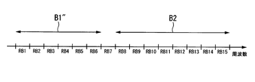
図6は、リソース決定部42による割り当て結果の例を示す図である。図6において、横軸は周波数である。また、符号RB1、RB2・・・RB15は、それぞれリソースブロックである。図6に示す例では、リソース決定部42は、第1の移動局装置110に、符号B1を付した周波数帯域(リソースブロックRB1からRB7)を割り当て、第2の移動局装置110に、符号B2を付した周波数帯域(リソースブロックRB8からRB15)を割り当てている。周波数帯域B1は、7リソースブロックであるので、対応するDFTポイント数は7×12=84である。84の素因数は、2、3、7であり、式(1)を満たさない。一方、周波数帯域B2は、8リソースブロックであるので、対応するDFTポイント数は8×12=96である。96の素因数は、2、3のみであり、式(1)を満たす。
図7は、本実施形態におけるスケジューリング部27による割り当て結果の例を示す図である。図7において、横軸は周波数である。図7の割り当て結果は、リソース決定部42が図6に示す割り当てを行ったときの、スケジューリング部27による割り当て結果の例である。図6の周波数帯域B1は、式(1)を満たさないので、RB調整部43は、周波数帯域B1にリソースブロックRB8を追加した周波数帯域B1’を、スケジューリング部27による第1の移動局装置110への割り当て結果としている。周波数帯域B1’は、リソースブロック数は8であるので、対応するDFTポイント数は8×12=96であり、式(1)を満たす。一方、図6の周波数帯域B2は、式(1)を満たすので、移動局装置選択部44は、リソース決定部42による割り当て結果である周波数帯域B2をそのままスケジューリング部27による第2の移動局装置110への割り当て結果としている。
図8は、従来の割り当て結果の例を示す図である。図8の例は、リソース決定部42が図6のように割り当てた場合と同様の状況における従来の割り当て結果である。非特許文献1などの従来の方法では、SC-FDMAを用いている場合、前述の条件A、Bに加えて、式(1)を満たすように割り当てる。このため、第2の移動局装置には、図7と同様に周波数帯域B2を割り当てるが、第1の移動局装置には、周波数帯域B1からリソースブロックB7を除いて、リソースブロックRB1からRB6からなる周波数帯域B1”を割り当てている。
このように、本実施形態では、第1の移動局装置110に周波数帯域B1’を割り当ててRB数(DFTポイント数)の制限を回避している。また、リソースブロックRB8において、第1の移動局装置110の割り当て周波数帯域と、第2の移動局装置110の割り当て周波数帯域とが重複するという非直交多重(無線リソースの共有方法という意味で非直交アクセスと呼んでもよい)を行う。これは、受信アンテナが2本以上であれば直交多重と考えることもできるため、直交多重と呼んでもよいが、ここでは意図的に部分的な重複を行うことを非直交多重と呼ぶ。このように、リソースブロックRB8の非直交アクセスとRB8以外の直交アクセスが混在するこのような直交/非直交ハイブリッドアクセスをRB数の制限の回避に使用することで、システム帯域全体のリソースに対して割り当てたリソースの使用率も高くすることができる。
このように、本実施形態では、第1の移動局装置110に周波数帯域B1’を割り当ててRB数(DFTポイント数)の制限を回避している。また、リソースブロックRB8において、第1の移動局装置110の割り当て周波数帯域と、第2の移動局装置110の割り当て周波数帯域とが重複するという非直交多重(無線リソースの共有方法という意味で非直交アクセスと呼んでもよい)を行う。これは、受信アンテナが2本以上であれば直交多重と考えることもできるため、直交多重と呼んでもよいが、ここでは意図的に部分的な重複を行うことを非直交多重と呼ぶ。このように、リソースブロックRB8の非直交アクセスとRB8以外の直交アクセスが混在するこのような直交/非直交ハイブリッドアクセスをRB数の制限の回避に使用することで、システム帯域全体のリソースに対して割り当てたリソースの使用率も高くすることができる。
このように、本実施形態は、割当不可能なリソースブロック数を避けつつ、割り当てるべきリソースブロックを各移動局装置110が使用することができ、その結果周波数利用効率が高まる。すなわち、DFTポイント数に制約があっても、周波数帯域の利用効率の低下を抑えることができる。さらに、例えば、図7に示されるように、システム全体のRB数が15であるのに対し、第1と第2の移動局装置に割り当てたRB数がそれぞれ8であることから、合計で16RB使っていることと等価である。したがって、一部のリソースブロックで無線リソースを多く割り当てることができることにより無線資源の利用効率も高い。
なお、本実施形態は、基地局装置120が、移動局装置110に周波数帯域を割り当てている。しかし、移動局装置110がRB調整部43を備え、基地局装置120が割り当てて通知した周波数帯域が割当不可能なリソースブロック数であるときに、移動局装置110のRB調整部43が、使用するリソースブロック数が割当不可能なリソースブロック数とならないように、使用するリソースブロック数を増加させるようにしてもよい。なお、どのリソースブロックを増やすかに関しては受信品質が把握できる場合には受信品質を用いてもよいし、予め決められたルールに基づいてもよい。例えば、割り当てられたリソースブロック数を越える最小の割当不可能でないリソースブロック数に高周波成分のリソースブロックを増やすなどといった方法などが考えられるが、一意に認識できればどのようなルールにしてもよい。
さらに、受信処理を行う基地局装置120では、複数の移動局装置110の信号が重複されて受信してもよい。また、この場合、基地局装置120では通知したリソースブロック数と異なるリソースブロック数で受信されることになるので、移動局装置110側から増加したリソースブロックのインデックスを通知するよう予め決定してもよいし、信号検出の際に増加させたリソースブロックの全ての候補に対して複数回信号処理を試みて、最も受信性能のよいものを検出結果とする方法を用いてもよい。
[第2の実施形態]
以下、図面を参照しながら、本発明の第2の実施形態について説明する。本実施形態では、上りリンクに、分割数(クラスタ数)に制約のないClustered DFT-S-OFDMAを用いる場合について説明する。ここで分割数とは、移動局装置110に割り当てる周波数帯域の分割数のことである。第1の実施形態では、割り当てる周波数帯域は、連続であったので、分割数は0である。Clustered DFT-S-OFDMAは、送信信号をDFTにより時間周波数変換して、サブキャリアに配置して送信するSC-FDMAとは他の例である。
本実施形態における無線通信システム100、移動局装置110及び基地局装置120の構成は図1、図2、図3、図4と同様であるため説明を省略する。ただし、基地局装置120のリソース決定部42の動作が、第1の実施形態とは異なる。第1の実施形態では、リソース決定部42は、周波数帯域の割り当てを行う際に、移動局装置110には周波数方向に連続したリソースブロックを割り当てるという条件Aを満たすようにしていた。しかし、本実施形態の上りリンクは、Clustered DFT-S-OFDMAを用いるので、本実施形態におけるリソース決定部42は、前述の条件Aの制約を受けずに周波数帯域の割り当てを行う。
さらに、受信処理を行う基地局装置120では、複数の移動局装置110の信号が重複されて受信してもよい。また、この場合、基地局装置120では通知したリソースブロック数と異なるリソースブロック数で受信されることになるので、移動局装置110側から増加したリソースブロックのインデックスを通知するよう予め決定してもよいし、信号検出の際に増加させたリソースブロックの全ての候補に対して複数回信号処理を試みて、最も受信性能のよいものを検出結果とする方法を用いてもよい。
[第2の実施形態]
以下、図面を参照しながら、本発明の第2の実施形態について説明する。本実施形態では、上りリンクに、分割数(クラスタ数)に制約のないClustered DFT-S-OFDMAを用いる場合について説明する。ここで分割数とは、移動局装置110に割り当てる周波数帯域の分割数のことである。第1の実施形態では、割り当てる周波数帯域は、連続であったので、分割数は0である。Clustered DFT-S-OFDMAは、送信信号をDFTにより時間周波数変換して、サブキャリアに配置して送信するSC-FDMAとは他の例である。
本実施形態における無線通信システム100、移動局装置110及び基地局装置120の構成は図1、図2、図3、図4と同様であるため説明を省略する。ただし、基地局装置120のリソース決定部42の動作が、第1の実施形態とは異なる。第1の実施形態では、リソース決定部42は、周波数帯域の割り当てを行う際に、移動局装置110には周波数方向に連続したリソースブロックを割り当てるという条件Aを満たすようにしていた。しかし、本実施形態の上りリンクは、Clustered DFT-S-OFDMAを用いるので、本実施形態におけるリソース決定部42は、前述の条件Aの制約を受けずに周波数帯域の割り当てを行う。
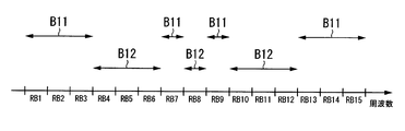
図9は、本実施形態におけるリソース決定部42による割り当て結果の例を示す図である。図9において、横軸は周波数である。また、符号RB1、RB2・・・RB15は、それぞれリソースブロックである。図9に示す例では、リソース決定部42は、第1の移動局装置110に、符号B11を付した周波数帯域(リソースブロックRB1~RB3、RB7、RB9、RB13~RB15)を割り当てている。また、第2の移動局装置110に、符号B12を付した周波数帯域(リソースブロックRB4~RB6、RB8、RB10~RB12)を割り当てている。周波数帯域B11は、8リソースブロックであるので、対応するDFTポイント数は8×12=96である。96の素因数は、2、3のみであり、式(1)を満たす。一方、周波数帯域B12は、7リソースブロックであるので、対応するDFTポイント数は7×12=84である。84の素因数は、2、3、7であり、式(1)を満たさない。
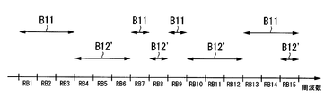
図10は、本実施形態におけるスケジューリング部27による割り当て結果の例を示す図である。図10において、横軸は周波数である。図10の割り当て結果は、リソース決定部42が図9に示す割り当てを行ったときの、スケジューリング部27による割り当て結果の例である。図9の周波数帯域B12は、式(1)を満たさないので、RB調整部43は、周波数帯域B12にリソースブロックRB15を追加した周波数帯域B12’を、スケジューリング部27による第2の移動局装置110への割り当て結果としている。周波数帯域B12’は、リソースブロック数は8であるので、対応するDFTポイント数は8×12=96であり、式(1)を満たす。一方、図9の周波数帯域B11は、式(1)を満たすので、移動局装置選択部44は、リソース決定部42による割り当て結果である周波数帯域B11をそのままスケジューリング部27による第1の移動局装置110への割り当て結果としている。
図11は、従来の割り当て結果の例を示す図である。図11の例は、リソース決定部42が図9のように割り当てた場合と同様の状況における従来の割り当て結果である。非特許文献1などの従来の方法では、分割数に制約のないClustered DFT-S-OFDMを用いている場合、前述の条件Bに加えて、式(1)を満たすように割り当てる。このため、第1の移動局装置には、図10と同様に周波数帯域B11を割り当てるが、第2の移動局装置には、周波数帯域B12からリソースブロックB8を除いて、リソースブロックRB4~RB6、RB10~RB12からなる周波数帯域B12”を割り当てている。
このように、上りリンクにClustered DFT-S-OFDMAを用いる場合でも、割当不可能なリソースブロック数を避けつつ、割り当てるべきリソースブロックを各移動局装置110が使用することができ、その結果周波数利用効率が高まる。このとき、図11のように、式(1)を満たすために空きRBを作ってしまい無線資源の利用効率を下げることを避けることができる。すなわち、DFTポイント数に制約があっても、周波数帯域の利用効率の低下を抑えることができる。
なお、本実施形態において、RB調整部43は、追加するリソースブロックとして、割り当て可能な周波数帯域のうち、最も優先度の値の大きいものから順に選択するようにしてもよいし、重複したRBの信号の分離をしやすいなどといった条件で選択するようにしてもよい。また、追加することで、割り当てる周波数帯域の分割数が減るものを選択するようにしてもよい。分割数を減らすことで、送信信号のPAPR(Peak to Average Power Ratio;ピーク対平均電力比)の改善や、帯域外輻射の削減などの効果を得ることができる。
[第3の実施形態]
以下、図面を参照しながら、本発明の第3の実施形態について説明する。本実施形態では、上りリンクに、分割数(クラスタ数)に制約のあるClustered DFT-S-OFDMAを用いる場合について説明する。本実施形態では、分割数が2である場合について説明する。
本実施形態における無線通信システム100、移動局装置110及び基地局装置120の構成は図1、図2、図3、図4と同様であるため説明を省略する。ただし、基地局装置120のリソース決定部42の動作が、第1および第2の実施形態とは異なる。本実施形態では、リソース決定部42は、周波数帯域の割り当てを行う際に、前述の条件Aに変えて、移動局装置110に割り当てるリソースブロック群は、2分割まで許容するという条件A’を満たすようにする。
なお、本実施形態において、RB調整部43は、追加するリソースブロックとして、割り当て可能な周波数帯域のうち、最も優先度の値の大きいものから順に選択するようにしてもよいし、重複したRBの信号の分離をしやすいなどといった条件で選択するようにしてもよい。また、追加することで、割り当てる周波数帯域の分割数が減るものを選択するようにしてもよい。分割数を減らすことで、送信信号のPAPR(Peak to Average Power Ratio;ピーク対平均電力比)の改善や、帯域外輻射の削減などの効果を得ることができる。
[第3の実施形態]
以下、図面を参照しながら、本発明の第3の実施形態について説明する。本実施形態では、上りリンクに、分割数(クラスタ数)に制約のあるClustered DFT-S-OFDMAを用いる場合について説明する。本実施形態では、分割数が2である場合について説明する。
本実施形態における無線通信システム100、移動局装置110及び基地局装置120の構成は図1、図2、図3、図4と同様であるため説明を省略する。ただし、基地局装置120のリソース決定部42の動作が、第1および第2の実施形態とは異なる。本実施形態では、リソース決定部42は、周波数帯域の割り当てを行う際に、前述の条件Aに変えて、移動局装置110に割り当てるリソースブロック群は、2分割まで許容するという条件A’を満たすようにする。
図12は、本実施形態におけるリソース決定部42による割り当て結果の例を示す図である。図12において、横軸は周波数である。また、符号RB1、RB2・・・RB15は、それぞれリソースブロックである。図12に示す例では、リソース決定部42は、第1の移動局装置110に、符号B21を付した周波数帯域(リソースブロックRB1~RB4、RB9~RB12)を割り当てている。また、第2の移動局装置110に、符号B22を付した周波数帯域(リソースブロックRB5~RB8、RB13~RB15)を割り当てている。周波数帯域B21は、8リソースブロックであるので、対応するDFTポイント数は8×12=96である。96の素因数は、2、3のみであり、式(1)を満たす。一方、周波数帯域B22は、7リソースブロックであるので、対応するDFTポイント数は7×12=84である。84の素因数は、2、3、7であり、式(1)を満たさない。
図13は、本実施形態におけるスケジューリング部27による割り当て結果の例を示す図である。図13において、横軸は周波数である。図13の割り当て結果は、リソース決定部42が図12に示す割り当てを行ったときの、スケジューリング部27による割り当て結果の例である。図12の周波数帯域B22は、式(1)を満たさないので、RB調整部43は、周波数帯域B22に、いずれかのリソースブロックを追加する。追加するリソースブロックは、既に割り当てられているリソースブロック群のいずれかの端に隣接するものなので、図12の場合、追加することができるRBは{RB4、RB9、RB12}である。これを割当可能なRBと定義する。RB調整部43は、これら割当可能なRBの中から優先度が最大のものを選択して追加する。具体的には、割当可能なRBの集合をSとし、割当不可能なリソースブロック数の移動局装置のインデックスをu’とすると、次式で割り当てるRBを決定する。

式(3)により決定されたインデックスmのRBをu’番目の移動局装置110に割り当てる。第1の実施形態の場合、集合Sに含まれるRBは第1の移動局装置110におけるRB8であり、第2の実施形態の場合はクラスタ数が無限であることから全てのRBが含まれる。
また、式(3)で1RB増加させてもなお割当不可能な周波数インデックスであった場合(例えば、14RBとなった場合など)は、式(3)で増加させたRBを割当リソースとして再度集合Sを定義し、式(3)によりさらに割当リソース数を増加させ、この処理を割当不可能なリソースブロック数でない状態になるまで繰り返すことでいかなる場合でも適用できる。
このようにしてリソースブロックRB12を追加した周波数帯域B22’を、スケジューリング部27による第2の移動局装置110への割り当て結果としている。周波数帯域B22’は、リソースブロック数は8であるので、対応するDFTポイント数は8×12=96であり、式(1)を満たす。一方、図12の周波数帯域B21は、式(1)を満たすので、移動局装置選択部44は、リソース決定部42による割り当て結果である周波数帯域B21をそのままスケジューリング部27による第1の移動局装置110への割り当て結果としている。
このようにしてリソースブロックRB12を追加した周波数帯域B22’を、スケジューリング部27による第2の移動局装置110への割り当て結果としている。周波数帯域B22’は、リソースブロック数は8であるので、対応するDFTポイント数は8×12=96であり、式(1)を満たす。一方、図12の周波数帯域B21は、式(1)を満たすので、移動局装置選択部44は、リソース決定部42による割り当て結果である周波数帯域B21をそのままスケジューリング部27による第1の移動局装置110への割り当て結果としている。
図14は、従来の割り当て結果の例を示す図である。図14の例は、リソース決定部42が図12のように割り当てた場合と同様の状況における従来の割り当て結果である。非特許文献1などの従来の方法では、前述の条件A’、Bに加えて、式(1)を満たすように割り当てる。このため、第1の移動局装置には、図12と同様に周波数帯域B21を割り当てるが、第2の移動局装置には、周波数帯域B22からリソースブロックB13を除いて、リソースブロックRB4~RB6、RB14~RB15からなる周波数帯域B22”を割り当てている。
このように、分割数に制限のあるClustered DFT-S-OFDMであっても、割当不可能なリソースブロック数を避けつつ、割り当てるべきリソースブロックを各移動局装置110が使用することができる。すなわち、DFTポイント数に制約があっても、周波数帯域の利用効率の低下を抑えることができる。さらに、一部のRBで無線リソースを多く割り当てていることと等価であるため、無線資源の利用効率も高い。
また、上述した各実施形態における移動局装置110および基地局装置120の一部、または全部の機能を実現するためのプログラムをコンピュータ読み取り可能な記録媒体に記録して、この記録媒体に記録されたプログラムをコンピュータシステムに読み込ませ、実行することにより移動局装置110および基地局装置120を実現してもよい。なお、ここでいう「コンピュータシステム」とは、OSや周辺機器等のハードウェアを含むものとする。
また、「コンピュータ読み取り可能な記録媒体」とは、フレキシブルディスク、光磁気ディスク、ROM、CD-ROM等の可搬媒体、コンピュータシステムに内蔵されるハードディスク等の記憶装置のことをいう。さらに「コンピュータ読み取り可能な記録媒体」とは、インターネット等のネットワークや電話回線等の通信回線を介してプログラムを送信する場合の通信線のように、短時間の間、動的にプログラムを保持するもの、その場合のサーバやクライアントとなるコンピュータシステム内部の揮発性メモリのように、一定時間プログラムを保持しているものも含むものとする。また上記プログラムは、前述した機能の一部を実現するためのものであっても良く、さらに前述した機能をコンピュータシステムにすでに記録されているプログラムとの組み合わせで実現できるものであっても良い。
また、上述した各実施形態における移動局装置110および基地局装置120の一部、または全部を典型的には集積回路であるLSIとして実現してもよい。移動局装置110および基地局装置120の各機能ブロックは個別にチップ化してもよいし、一部、または全部を集積してチップ化してもよい。また、集積回路化の手法はLSIに限らず専用回路、または汎用プロセッサで実現しても良い。また、半導体技術の進歩によりLSIに代替する集積回路化の技術が出現した場合、当該技術による集積回路を用いることも可能である。
また、上述した各実施形態における移動局装置110および基地局装置120の一部、または全部を典型的には集積回路であるLSIとして実現してもよい。移動局装置110および基地局装置120の各機能ブロックは個別にチップ化してもよいし、一部、または全部を集積してチップ化してもよい。また、集積回路化の手法はLSIに限らず専用回路、または汎用プロセッサで実現しても良い。また、半導体技術の進歩によりLSIに代替する集積回路化の技術が出現した場合、当該技術による集積回路を用いることも可能である。
以上、この発明の実施形態を図面を参照して詳述してきたが、具体的な構成はこの実施形態に限られるものではなく、この発明の要旨を逸脱しない範囲の設計変更等も含まれる。
本発明は、携帯電話装置を移動局装置とする移動体通信システムに用いて好適であるが、これに限定されない。
1…符号部
2…変調部
3…DFT部
4…リソース割当部
5…復調用参照信号多重部
6…IFFT部
7…切替部
8…サウンディング参照信号多重部
9…CP挿入部
10…送信部
11…送信アンテナ
12…受信部
13…制御情報検出部
14…MCS識別部
15…リソース識別部
16…復調用参照信号生成部
17…サウンディング参照信号生成部
18…受信アンテナ
21…受信アンテナ
22…受信部
23…CP除去部
24…切替部
25…サウンディング参照信号分離部
26…伝搬路サウンディング部
27…スケジューリング部
28…制御信号生成部
29…送信部
30…FFT部
31…復調用参照信号分離部
32…伝搬路推定部
33…リソース分離部
34…信号検出部
35…送信アンテナ
41…優先度算出部
42…リソース決定部
43…RB調整部
44…移動局装置選択部
100…無線通信システム
110…移動局装置
120…基地局装置
2…変調部
3…DFT部
4…リソース割当部
5…復調用参照信号多重部
6…IFFT部
7…切替部
8…サウンディング参照信号多重部
9…CP挿入部
10…送信部
11…送信アンテナ
12…受信部
13…制御情報検出部
14…MCS識別部
15…リソース識別部
16…復調用参照信号生成部
17…サウンディング参照信号生成部
18…受信アンテナ
21…受信アンテナ
22…受信部
23…CP除去部
24…切替部
25…サウンディング参照信号分離部
26…伝搬路サウンディング部
27…スケジューリング部
28…制御信号生成部
29…送信部
30…FFT部
31…復調用参照信号分離部
32…伝搬路推定部
33…リソース分離部
34…信号検出部
35…送信アンテナ
41…優先度算出部
42…リソース決定部
43…RB調整部
44…移動局装置選択部
100…無線通信システム
110…移動局装置
120…基地局装置
Claims (13)
- 送信信号を直交変換し、サブキャリアに配置して送信する複数の通信装置の各々に、前記サブキャリアの周波数帯域を割り当てる割り当て決定部と、
前記複数の通信装置のうち、前記割当て決定部が割り当てた周波数帯域に含まれるサブキャリアの数が、所定の数ではない前記通信装置を選択する通信装置選択部と、
前記選択した通信装置の各々に割り当てる周波数帯域を、前記割当て決定部が割り当てた周波数帯域から変更する周波数帯域調整部と
を具備し、
前記周波数帯域調整部は、前記変更の結果の周波数帯域の各々に含まれるサブキャリアの数が、前記所定の数となるように、前記変更を行うこと
を特徴とする基地局装置。 - 前記割り当て決定部は、前記複数の通信装置の間で、割り当てられる周波数帯域が重複しないように、前記周波数帯域の割り当てを行い、
前記周波数帯域調整部は、前記選択した通信装置と他の前記通信装置との間で、割り当てられる周波数帯域の重複を許容し、かつ、前記割り当て決定部が割り当てた周波数帯域に対して周波数帯域を追加することで、前記変更を行うこと
を特徴とする請求項1に記載の基地局装置。 - 前記周波数帯域調整部は、前記周波数帯域の追加を行う際、割り当て可能な周波数帯域のうち、優先度の高いものから順に追加することを特徴とする請求項2に記載の基地局装置。
- 前記周波数帯域調整部が追加する周波数帯域は、前記割り当て決定部が割り当てた周波数帯域に隣接する周波数帯域であることを特徴とする請求項2に記載の基地局装置。
- 前記複数の通信装置が送信した信号を受信する受信部と、
前記受信した信号から前記通信装置各々の信号を検出する信号検出部と
を具備し、
前記信号検出部は、前記割り当てられた周波数帯域が他の前記通信装置と重複している前記通信装置の信号については、干渉キャンセリングを行って、前記受信した信号から分離すること
を特徴とする請求項2に記載の基地局装置。 - 前記干渉キャンセリングは、ターボ原理に基づく非線形繰り返し等化またはシリアル干渉キャンセリングであることを特徴とする請求項5に記載の基地局装置。
- 前記直交変換は、時間周波数変換であることを特徴とする請求項1に記載の基地局装置。
- 複数の通信装置と、基地局装置とを具備する無線通信システムであって、
前記通信装置は、送信信号を直交変換し、サブキャリアに配置して送信する送信部を具備し、
前記基地局装置は、前記通信装置の各々に、前記サブキャリアの周波数帯域を割り当てる割り当て決定部を具備し、
前記基地局装置または前記通信装置は、前記割当て決定部が割り当てた周波数帯域に含まれるサブキャリアの数が、所定の数であるときは、前記割当て決定部が割り当てた周波数帯域を変更する周波数帯域調整部を具備し、
前記周波数帯域調整部は、前記変更の結果の周波数帯域に含まれるサブキャリアの数が、前記所定の数とならないように、前記変更を行うこと
を特徴とする無線通信システム。 - 送信信号を直交変換し、基地局装置が割り当てた周波数帯域のサブキャリアに、前記直交変換した信号を配置して送信する無線通信装置であって、
前記基地局装置が割り当てた周波数帯域に含まれるサブキャリアの数が、所定の数であるときは、前記基地局装置が割り当てた周波数帯域を変更する周波数帯域調整部
を具備し、
前記周波数帯域調整部は、前記変更の結果の周波数帯域に含まれるサブキャリアの数が、前記所定の数とならないように、前記変更を行うこと
を特徴とする無線通信装置。 - 基地局装置における周波数帯域割り当て方法であって、
送信信号を直交変換し、サブキャリアに配置して送信する複数の通信装置の各々に、前記サブキャリアの周波数帯域を割り当てる第1の過程と、
前記複数の通信装置のうち、前記第1の過程にて割り当てた周波数帯域に含まれるサブキャリアの数が、所定の数ではない前記通信装置を選択する第2の過程と、
前記選択した通信装置の各々に割り当てる周波数帯域を、前記第1の過程が割り当てた周波数帯域から変更する第3の過程と
を有し、
前記第3の過程において、前記変更の結果の周波数帯域の各々に含まれるサブキャリアの数が、前記所定の数となるように、前記変更を行うこと
を特徴とする周波数帯域割り当て方法。 - 送信信号を直交変換し、基地局装置が割り当てた周波数帯域のサブキャリアに、前記直交変換した信号を配置して送信する無線通信装置における周波数帯域割り当て方法であって、
前記基地局装置が割り当てた周波数帯域に含まれるサブキャリアの数が、所定の数であるときは、前記基地局装置が割り当てた周波数帯域を変更する第1の過程
を有し、
前記第1の過程は、前記変更の結果の周波数帯域に含まれるサブキャリアの数が、前記所定の数とならないように、前記変更を行うこと
を特徴とする周波数帯域割り当て方法。 - 基地局装置のコンピュータを、
送信信号を直交変換し、サブキャリアに配置して送信する複数の通信装置の各々に、前記サブキャリアの周波数帯域を割り当てる割り当て決定部、
前記複数の通信装置のうち、前記割当て決定部が割り当てた周波数帯域に含まれるサブキャリアの数が、所定の数ではない前記通信装置を選択する通信装置選択部、
前記選択した通信装置の各々に割り当てる周波数帯域を、前記割当て決定部が割り当てた周波数帯域から変更する周波数帯域調整部
として機能させるためのプログラムであって、
前記周波数帯域調整部は、前記変更の結果の周波数帯域の各々に含まれるサブキャリアの数が、前記所定の数となるように、前記変更を行うこと
を特徴とするプログラム。 - 送信信号を直交変換し、基地局装置が割り当てた周波数帯域のサブキャリアに、前記直交変換した信号を配置して送信する無線通信装置のコンピュータを、
前記基地局装置が割り当てた周波数帯域に含まれるサブキャリアの数が、所定の数であるときは、前記基地局装置が割り当てた周波数帯域を変更する周波数帯域調整部
として機能させるためのプログラムであって、
前記周波数帯域調整部は、前記変更の結果の周波数帯域に含まれるサブキャリアの数が、前記所定の数とならないように、前記変更を行うこと
を特徴とするプログラム。
Priority Applications (1)
| Application Number | Priority Date | Filing Date | Title |
|---|---|---|---|
| US14/362,631 US20140341179A1 (en) | 2011-12-05 | 2012-12-05 | Base station device, wireless communication system, wireless communication device, frequency band allocation method, and program |
Applications Claiming Priority (2)
| Application Number | Priority Date | Filing Date | Title |
|---|---|---|---|
| JP2011-266001 | 2011-12-05 | ||
| JP2011266001A JP2013118586A (ja) | 2011-12-05 | 2011-12-05 | 基地局装置、無線通信システム、無線通信装置、周波数帯域割り当て方法およびプログラム |
Publications (1)
| Publication Number | Publication Date |
|---|---|
| WO2013084908A1 true WO2013084908A1 (ja) | 2013-06-13 |
Family
ID=48574266
Family Applications (1)
| Application Number | Title | Priority Date | Filing Date |
|---|---|---|---|
| PCT/JP2012/081448 Ceased WO2013084908A1 (ja) | 2011-12-05 | 2012-12-05 | 基地局装置、無線通信システム、無線通信装置、周波数帯域割り当て方法およびプログラム |
Country Status (3)
| Country | Link |
|---|---|
| US (1) | US20140341179A1 (ja) |
| JP (1) | JP2013118586A (ja) |
| WO (1) | WO2013084908A1 (ja) |
Cited By (1)
| Publication number | Priority date | Publication date | Assignee | Title |
|---|---|---|---|---|
| CN106416407A (zh) * | 2014-04-30 | 2017-02-15 | 意大利电信股份公司 | 为蜂窝网络中上行链路传输分配无线电资源的方法和系统 |
Families Citing this family (8)
| Publication number | Priority date | Publication date | Assignee | Title |
|---|---|---|---|---|
| JP5873103B2 (ja) * | 2011-11-07 | 2016-03-01 | パナソニック インテレクチュアル プロパティ コーポレーション オブアメリカPanasonic Intellectual Property Corporation of America | 中継局、基地局及び帯域割当方法 |
| US10862634B2 (en) * | 2014-03-07 | 2020-12-08 | Huawei Technologies Co., Ltd. | Systems and methods for OFDM with flexible sub-carrier spacing and symbol duration |
| JP6422112B2 (ja) * | 2014-07-14 | 2018-11-14 | Necプラットフォームズ株式会社 | 中継装置、通信制御方法及びプログラム |
| EP3437201B1 (en) * | 2016-03-31 | 2021-07-28 | British Telecommunications public limited company | Method and apparatus for transmitting data over a plurality of pairs of wires |
| US10856310B2 (en) * | 2017-02-03 | 2020-12-01 | Qualcomm Incorporated | Retuning in machine type communications |
| MX2021000132A (es) * | 2018-11-01 | 2021-03-25 | Panasonic Ip Corp America | Estacion movil, estacion base, metodo de transmision y metodo de recepcion. |
| US11245552B2 (en) * | 2019-03-29 | 2022-02-08 | Skyworks Solutions, Inc. | Sounding reference signal switching |
| US11956108B2 (en) | 2021-06-14 | 2024-04-09 | Skyworks Solutions, Inc. | Antenna swapping without blanking symbols |
Citations (3)
| Publication number | Priority date | Publication date | Assignee | Title |
|---|---|---|---|---|
| JP2008124843A (ja) * | 2006-11-13 | 2008-05-29 | Matsushita Electric Ind Co Ltd | 無線受信装置 |
| WO2009154250A1 (ja) * | 2008-06-20 | 2009-12-23 | シャープ株式会社 | 通信システム、通信装置、プログラム及び通信方法 |
| WO2011149015A1 (ja) * | 2010-05-26 | 2011-12-01 | シャープ株式会社 | 無線通信システム、基地局装置、および周波数割当方法 |
Family Cites Families (4)
| Publication number | Priority date | Publication date | Assignee | Title |
|---|---|---|---|---|
| EP3393066B1 (en) * | 2006-11-01 | 2021-12-01 | LG Electronics Inc. | Method and apparatus for allocating pilots |
| WO2008081876A1 (ja) * | 2006-12-28 | 2008-07-10 | Sharp Kabushiki Kaisha | 無線送信装置、制御装置、無線通信システムおよび通信方法 |
| JP5086880B2 (ja) * | 2008-04-22 | 2012-11-28 | シャープ株式会社 | 送信装置、受信装置及び無線通信システム |
| WO2010000309A1 (en) * | 2008-07-01 | 2010-01-07 | Telefonaktiebolaget L M Ericsson (Publ) | Method and arrangement in a telecommunication system |
-
2011
- 2011-12-05 JP JP2011266001A patent/JP2013118586A/ja active Pending
-
2012
- 2012-12-05 WO PCT/JP2012/081448 patent/WO2013084908A1/ja not_active Ceased
- 2012-12-05 US US14/362,631 patent/US20140341179A1/en not_active Abandoned
Patent Citations (3)
| Publication number | Priority date | Publication date | Assignee | Title |
|---|---|---|---|---|
| JP2008124843A (ja) * | 2006-11-13 | 2008-05-29 | Matsushita Electric Ind Co Ltd | 無線受信装置 |
| WO2009154250A1 (ja) * | 2008-06-20 | 2009-12-23 | シャープ株式会社 | 通信システム、通信装置、プログラム及び通信方法 |
| WO2011149015A1 (ja) * | 2010-05-26 | 2011-12-01 | シャープ株式会社 | 無線通信システム、基地局装置、および周波数割当方法 |
Non-Patent Citations (2)
| Title |
|---|
| "3rd Generation Partnership Project;Technical Specification Group Radio Access Network; Evolved Universal Terrestrial Radio Access (E-UTRA);Physical Channels and Modulation (Release 10)", 3GPP TS 36.211 V10.3.0, September 2011 (2011-09-01) * |
| KAZUNARI YOKOMAKURA ET AL.: "A Spectrum- Overlapped Resource Management using Dynamic Spectrum Control", 2008 NEN THE INSTITUTE OF ELECTRONICS, INFORMATION AND COMMUNICATION ENGINEERS SOGO TAIKAI TSUSHIN KOEN RONBUNSHU 1, 18 March 2008 (2008-03-18), pages 437 * |
Cited By (2)
| Publication number | Priority date | Publication date | Assignee | Title |
|---|---|---|---|---|
| CN106416407A (zh) * | 2014-04-30 | 2017-02-15 | 意大利电信股份公司 | 为蜂窝网络中上行链路传输分配无线电资源的方法和系统 |
| CN106416407B (zh) * | 2014-04-30 | 2019-09-03 | 意大利电信股份公司 | 为蜂窝网络中上行链路传输分配无线电资源的方法和系统 |
Also Published As
| Publication number | Publication date |
|---|---|
| JP2013118586A (ja) | 2013-06-13 |
| US20140341179A1 (en) | 2014-11-20 |
Similar Documents
| Publication | Publication Date | Title |
|---|---|---|
| US20240064790A1 (en) | Device and method for associating resource information with channel metric information in wireless networks | |
| JP5900884B2 (ja) | 制御局装置、および無線通信システム | |
| WO2013084908A1 (ja) | 基地局装置、無線通信システム、無線通信装置、周波数帯域割り当て方法およびプログラム | |
| RU2436252C2 (ru) | Способ передачи управляющих сигналов в системе беспроводной связи | |
| JP5536206B2 (ja) | 非連続的なリソースクラスタでの基準信号の伝送 | |
| US10237110B2 (en) | Synchronization method and apparatus in mobile communication system | |
| EP2649851B1 (en) | Resource allocation in a wireless communication system | |
| RU2472292C2 (ru) | Устройство и способ назначения поднесущих при кластерном мультиплексировании с ортогональным частотным разделением и дискретным преобразованием фурье | |
| US9220108B2 (en) | Scheduling method and control station apparatus | |
| KR101093331B1 (ko) | 무선 통신 시스템에서의 신호 다중 방법 및 송신국 | |
| JP5554205B2 (ja) | 無線送信装置、無線受信装置、無線通信システム、無線送信装置の制御プログラムおよび集積回路 | |
| KR20190098237A (ko) | 기준 신호 전송 방법 및 장치 | |
| KR101878504B1 (ko) | 무선 통신 장치, 할당 리소스 통지 방법 및 데이터 할당 방법 | |
| WO2012115087A1 (ja) | 無線通信システム、無線通信方法、送信装置、及びプロセッサ | |
| EP3567819A1 (en) | Method, device and system for use in wireless communication | |
| JP5066536B2 (ja) | 移動端末装置、無線基地局装置および無線アクセス方法 | |
| JP2010081349A (ja) | 無線通信システム、通信装置、スケジューリング方法およびプログラム | |
| US20150208412A1 (en) | Communication system, communication device, and communication method | |
| JP6664131B2 (ja) | 割当装置、コンピュータに実行させるためのプログラムおよびプログラムを記録したコンピュータ読み取り可能な記録媒体 | |
| JP5441811B2 (ja) | 受信装置、基地局装置、無線通信システム、伝搬路推定方法、制御プログラムおよび集積回路 | |
| JP5938019B2 (ja) | 無線通信システム、無線通信装置、及び無線通信方法 | |
| JP6279207B2 (ja) | 受信装置及び干渉雑音電力推定方法 | |
| JP5947749B2 (ja) | 無線通信方式、無線通信装置、及び無線通信方法 | |
| CN121711221A (zh) | 信号传输方法、通信装置、存储介质及程序产品 | |
| JP2014131112A (ja) | 無線送信装置、制御装置、無線通信システムおよび通信方法 |
Legal Events
| Date | Code | Title | Description |
|---|---|---|---|
| 121 | Ep: the epo has been informed by wipo that ep was designated in this application |
Ref document number: 12855936 Country of ref document: EP Kind code of ref document: A1 |
|
| WWE | Wipo information: entry into national phase |
Ref document number: 14362631 Country of ref document: US |
|
| NENP | Non-entry into the national phase |
Ref country code: DE |
|
| 122 | Ep: pct application non-entry in european phase |
Ref document number: 12855936 Country of ref document: EP Kind code of ref document: A1 |