WO2013084797A1 - リール部材及びフィルム収容体 - Google Patents
リール部材及びフィルム収容体 Download PDFInfo
- Publication number
- WO2013084797A1 WO2013084797A1 PCT/JP2012/080987 JP2012080987W WO2013084797A1 WO 2013084797 A1 WO2013084797 A1 WO 2013084797A1 JP 2012080987 W JP2012080987 W JP 2012080987W WO 2013084797 A1 WO2013084797 A1 WO 2013084797A1
- Authority
- WO
- WIPO (PCT)
- Prior art keywords
- adhesive film
- flange
- reel member
- thickness
- core shaft
- Prior art date
- Legal status (The legal status is an assumption and is not a legal conclusion. Google has not performed a legal analysis and makes no representation as to the accuracy of the status listed.)
- Ceased
Links
Images
Classifications
-
- B—PERFORMING OPERATIONS; TRANSPORTING
- B65—CONVEYING; PACKING; STORING; HANDLING THIN OR FILAMENTARY MATERIAL
- B65H—HANDLING THIN OR FILAMENTARY MATERIAL, e.g. SHEETS, WEBS, CABLES
- B65H75/00—Storing webs, tapes, or filamentary material, e.g. on reels
- B65H75/02—Cores, formers, supports, or holders for coiled, wound, or folded material, e.g. reels, spindles, bobbins, cop tubes, cans, mandrels or chucks
- B65H75/04—Kinds or types
- B65H75/08—Kinds or types of circular or polygonal cross-section
- B65H75/14—Kinds or types of circular or polygonal cross-section with two end flanges
-
- B—PERFORMING OPERATIONS; TRANSPORTING
- B65—CONVEYING; PACKING; STORING; HANDLING THIN OR FILAMENTARY MATERIAL
- B65H—HANDLING THIN OR FILAMENTARY MATERIAL, e.g. SHEETS, WEBS, CABLES
- B65H2701/00—Handled material; Storage means
- B65H2701/30—Handled filamentary material
- B65H2701/37—Tapes
- B65H2701/377—Adhesive tape
Definitions
- the present invention relates to a reel member technique for winding and drawing out a series of long adhesive films such as anisotropic conductive adhesive films.
- an anisotropic conductive adhesive film in which conductive particles are dispersed in an insulating adhesive is used.
- a conductive adhesive film containing conductive particles in an insulating adhesive has been used as an adhesive film for electrically connecting and bonding electrodes for solar cells.
- Such an adhesive film is formed on a narrow and long release sheet, and is shipped in the form of a reel member wound up in a roll shape.
- the present invention has been made in consideration of the above-described problems of the prior art.
- the object of the present invention is to provide a reel member that winds and pulls out a long adhesive film, and a flange outer peripheral portion due to its own weight. It is an object of the present invention to provide a technique for improving the accuracy of the clearance between flanges by preventing the deflection.
- the present invention made to achieve the above object includes a core shaft portion formed in a cylindrical shape and capable of winding an adhesive film, and first and second flanges provided at both ends of the core shaft portion.
- a reinforcing portion having a constant thickness in the vicinity of the core shaft portion of the first and second flange portions, and an inner portion of the first and second flange portions, and
- a weight reduction part formed so that the thickness is thinner than the thickness of the reinforcement part is provided on the flange outer peripheral side with respect to the reinforcement part, and further, on the inner part of the first and second flange parts, It is a reel member provided with a rib for guiding the adhesive film.
- the lightening portion is formed in a tapered shape so that the thickness decreases from the reinforcing portion toward the outer peripheral portion of the flange.
- the rib is also effective when the surface for guiding the adhesive film is provided on a surface orthogonal to the rotation direction of the reel member.
- this invention is a film container which has one of the reel members mentioned above, and the adhesive film wound up by the core shaft part of the said reel member.
- the adhesive film is an anisotropic conductive adhesive film in which conductive particles are dispersed in an insulating adhesive.
- a reinforcing portion having a certain thickness is provided in the vicinity of the core shaft portion of the first and second flange portions, and is provided at the inner portion of the first and second flange portions and with respect to the reinforcing portion.
- the flange portion is provided with a lighter weight portion, for example, tapered so that the thickness is thinner than the thickness of the reinforcing portion. Since the weight of the outer peripheral portions of the first and second flange portions can be reduced, and the deflection of the flange outer peripheral portion due to the weight of the reel member can be prevented, the first and second flanges can be prevented. The accuracy of the clearance between the flange portions can be improved.
- the ribs for guiding the adhesive film are provided in the inner portions of the first and second flange portions, the meandering of the adhesive film at the time of winding and drawing can be prevented. As a result, it is possible to prevent the adhesive film from dropping off during winding and the adhesive film from being caught or blocked during drawing.
- the surface of the rib for guiding the adhesive film is provided on the surface orthogonal to the rotation direction of the reel member, Since meandering can be more reliably prevented, it is possible to more reliably prevent the adhesive film from dropping off at the time of winding and the adhesive film from being caught or blocked at the time of withdrawal.
- the deflection of the outer peripheral portion of the flange due to the weight of the reel member can be prevented, so that the accuracy of the clearance between the first and second flange portions can be prevented. Can be improved.
- FIG. 1 Plan view showing the inner structure of the embodiment of the reel member according to the present invention
- (c): B— of FIG. 1 (a) B line cross section Sectional drawing which shows the whole structure of the reel member Sectional drawing which shows the whole structure of embodiment of the film container which concerns on this invention
- Explanatory drawing which shows the dimensional relationship of each part in the reel member of this invention
- Sectional drawing which shows the structure of the reel member of the comparative examples 1 and 2
- Sectional drawing which shows the structure of the reel member of the comparative example 3
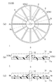
- FIG. 1A is a plan view showing an inner configuration of an embodiment of a reel member according to the present invention
- FIG. 1B is a cross-sectional view taken along line AA of FIG. 1A
- FIG. ) Is a cross-sectional view taken along the line BB of FIG.
- the reel member 1 of the present embodiment is made of polystyrene resin from the viewpoint of ensuring dimensional stability. As shown in FIGS. 1A to 1C, the reel member 1 is driven by a film winding device or a film drawing device. The shaft 10 is attached.
- the reel member 1 has, for example, a cylindrical core shaft portion 2 around which a long adhesive film such as an anisotropic conductive adhesive film is wound.
- the first and second flange portions 11 and 12 are integrally provided.
- the first and second flange portions 11 and 12 are formed so that the outer surfaces thereof are planes orthogonal to the rotation axis O, and have the same configuration.
- the 1st flange part 11 it demonstrates taking the 1st flange part 11 as an example.
- a circular reinforcing portion 3 is provided around the core shaft portion 2 of the first flange portion 11.
- the reinforcing portion 3 has an inner surface formed parallel to the outer surface of the first flange portion 11 and is formed to have a constant width.
- a lighter portion 4 is provided on the inner peripheral portion of the first flange portion 11 on the outer peripheral portion side with respect to the reinforcing portion 3.
- the lightening portion 4 is formed in a tapered shape so that the thickness is thinner than the reinforcing portion 3 from the reinforcing portion 3 toward the outer peripheral portion side.
- the surface (inner side surface) of the light weight portion 4 is formed in a flat shape.
- ribs 5 for guiding the adhesive film are provided on the inner portion of the first flange portion 11 and on the outer peripheral portion side with respect to the core shaft portion 2.
- the rib 5 has a plurality of inner guide portions 5 a that extend radially around the rotation axis O of the reel member 1 and a circular outer guide portion 5 b provided on the outer edge of the first flange portion 11. is doing.
- Each portion of the rib 5 is placed on a plane parallel to the outer surface 11a of the first flange portion 11, that is, on a plane orthogonal to the rotation axis O so that the height is slightly higher than the reinforcing portion 3.
- a predetermined radius is applied to each top surface of the rib 5.
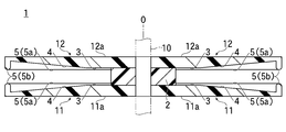
- FIG. 2 is a cross-sectional view showing the overall configuration of the reel member of the present embodiment.
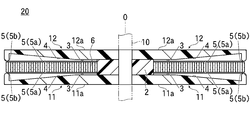
- FIG. 3 is sectional drawing which shows the whole structure of embodiment of the film container which concerns on this invention.
- the reel member 1 shown in FIG. 2 is mounted on a film take-up device (not shown), and a long adhesive film 6 is wound around the core shaft 2 to obtain the film container 20 shown in FIG.
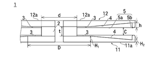
- FIG. 4 is an explanatory view showing the dimensional relationship of each part in the reel member 1 of the present invention.
- the reel member 1 according to the present invention is effective for a long (300 to 600 m) adhesive film 6 and has first and second flange portions 11 and 12 having large diameters.
- the diameters of the first and second flange portions 11 and 12 are 250 to 300 mm, and the distance between the first and second flange portions 11 and 12, that is, the thickness t of the core shaft portion 2 is 1.00. This is particularly effective when the thickness is ⁇ 1.30 mm.
- the diameter d of the core shaft portion 2 is (diameter of the first and second flange portions 11 and 12 / 2.5) from the viewpoint of securing necessary rigidity and reducing the weight of the outer peripheral portion of the flange. It is preferable to set to ⁇ 10%. In this case, it is preferable to set to about 100 mm from the viewpoint of reducing the weight of the outer peripheral portion of the flange.
- the diameter D of the reinforcing portion 3 is (diameter of the first and second flange portions 11 and 12 / 1.5) ⁇ 10% from the viewpoint of securing necessary rigidity and reducing the weight of the outer peripheral portion of the flange. It is preferable to set to. Specifically, the diameter D of the reinforcing portion 3 is preferably 183 to 150 mm, but is preferably set to about 150 mm from the viewpoint of reducing the weight.
- the ratio H 1 : H 2 of the thickness of the center side end portion and the outer peripheral side end portion of the lightening portion 4 is preferably from the viewpoint of securing necessary rigidity and reducing the weight of the flange outer peripheral portion.
- the size H 1 of the preferred lightening portion 4 on the center side is 1.90 to 2.10 mm
- the preferred size H 2 of the lightening portion 4 on the outer peripheral side is 1.45 to 1.55 mm.
- the height h of the outer peripheral portion (outer guide portion 5b) of the rib 5 is preferably 0.4 to 0.5 mm from the viewpoint of securing necessary rigidity and reducing the weight of the flange outer peripheral portion.
- the interval (clearance) C between the ribs 5 is 0.05 to 0. 0 with respect to the width of the adhesive film 6 from the viewpoint of preventing the adhesive film from sticking to the rib surface and preventing the adhesive film from dropping into the gap. It is preferable to set so as to be 10 mm apart.
- the number of the inner guide portions 5a of the rib 5 is preferably increased as the reel diameter increases. In the range to which the present invention is applied, 8 to 24 are preferable, and 12 to 24 are more preferable.
- the adhesive film 6 may be left in a horizontal position after winding the adhesive film 6 or may be displaced during transportation.
- the number of the inner guide portions 5a of the rib 5 If there are more than 24, there is a possibility that the adhesive film 6 may run up during winding, and at the same time, the risk of adhesion of the adhesive film 6 to the rib surface increases.
- the reinforcing portion 3 having a certain thickness is provided in the vicinity of the core shaft portion 2 of the first and second flange portions 11 and 12, and the first and second flange portions 11 are provided. , 12 and a portion on the outer peripheral side of the flange with respect to the reinforcing portion 3 is provided with a lightening portion 4 formed in a tapered shape so that the thickness is thinner than the thickness of the reinforcing portion 3. Therefore, the rigidity of the reel member 1 can be ensured by the reinforcing portion 3 having a certain thickness, and the weight of the outer peripheral portions of the first and second flange portions 11 and 12 can be reduced. Since the deflection of the outer peripheral portion of the flange due to its own weight can be prevented, the accuracy of the clearance between the first and second flange portions 11 and 12 can be improved.
- ribs 5 for guiding the adhesive film 6 are provided on the inner portions of the first and second flange portions 11 and 12, and the surface of the rib 5 for guiding the adhesive film 6 is provided. Since the reel member 1 is provided so as to be positioned on a surface orthogonal to the rotation direction of the reel member 1, the meandering of the adhesive film 6 at the time of winding and pulling out can be surely prevented. It is possible to reliably prevent the adhesive film 6 from dropping off at the time of take-off and the adhesive film 6 from being caught or blocked from being taken out.
- the minimum melt viscosity of the anisotropic conductive adhesive film is 3.0 ⁇ 10 4 Pa ⁇ s.
- This minimum melt viscosity is a value measured by using a measuring plate having a diameter of 8 mm, using a rotary rheometer (manufactured by TA instrument), keeping the heating rate constant at 10 ° C./min, measuring pressure at 5 g. is there.
- Example 1 As the reel member 1, a double-sided flange type made of polystyrene resin, having a diameter of the core shaft portion 2 of 100 mm, a thickness of 1.25 mm, and a diameter of the first and second flange portions 11 and 12 of 250 mm is used. It was. This is of the configuration shown in FIG.
- the reinforcing portion 3 of the reel member 1 has a thickness of 2.0 mm and a width D of 150 mm. Further, the light weight portion 4 is formed in a flat tapered shape, the height H 1 at the flange inner peripheral portion is 2.0 mm which is the same as the thickness of the reinforcing portion 3, and the thickness H 2 at the flange outer peripheral portion is 1.5 mm. It was made to become.
- the height h at the flange outer peripheral portion (outer guide portion 5 b) of the rib 5 was set to 0.5 mm from the inner surfaces of the first and second flange portions 11 and 12. Further, twelve inner guide portions 5a of the rib 5 are provided at equal intervals.
- An anisotropic conductive adhesive film 6 having a length of 500 m was wound around the reel member 1 as the adhesive film 6.
- a reel member 1C was prepared under the same conditions as in the example except that a tapered lightening portion 4A was formed without providing a reinforcing portion, and an adhesive film 6 having a length of 500 m was wound up. .
- the adhesive film 6 was drawn out for 1 second at a pulling tension of 50 g and a pulling speed of 500 mm / second with an interval of 1 second until the end, and the state of the adhesive film 6 at the time of drawing and after drawing (at the time of drawing) Catch, blocking, and cutting) were visually observed.
- the results are shown in Table 1.
- Comparative Example 3 in which the tapered lightening portion 4A is formed on the inner side surfaces of the first and second flange portions 11 and 12, while the height of the rib 5B is 0.1 mm from the inner side surface of the reel member 1B.
- the clearance deviation in the outer peripheral portion of the flange is large (1.15 ⁇ 0.2 mm), and adhesion is performed during winding.
- the film 6 was unwound and dropped.
- the taper-shaped lightweight part 4A in the inner surface of the 1st and 2nd flange parts 11 and 12, it is the comparative example 4 which made the height of the rib 5 in the flange outer peripheral part 0.5 mm same as an Example. Then, the length of the adhesive film 6 could be increased to 500 m, but the clearance deviation in the outer peripheral portion of the flange was large (1.15 ⁇ 0.2 mm), and it was caught when pulled out.
- the reinforcing portion 3 and the tapered lightening portion 4 are formed on the inner side surfaces of the first and second flange portions 11 and 12, and the height of the rib 5 at the outer peripheral portion of the flange is 0.5 mm.
- the clearance deviation at the outer peripheral portion of the flange is small (1.15 ⁇ 0.1 mm). It was 1 mm or less. Furthermore, in the examples, no problems occurred during winding and withdrawal.
Landscapes
- Storage Of Web-Like Or Filamentary Materials (AREA)
Abstract
リール部材(1)は、円筒形状の巻芯軸部(2)と、巻芯軸部(2)の両端部に設けられる第1 及び第2 フランジ部(11,12)とを有する。巻芯軸部(2)のまわりに接着フィルム(6)が巻かれる。フランジ部(11,12)の巻芯軸部(2)の近傍に、一定の厚さの補強部(3)がある。フランジ部(11,12)の内側、かつ、補強部(3)に対してフランジ外周側に、軽量化部(4)がある。軽量化部(4)の厚さは、補強部(3)の厚さより薄い。軽量化部(4)は、テーパ状に形成され、フランジ外周側において最も薄い。フランジ部(11,12)の内側部分に、接着フィルム(6)を案内するためのリブ(5)がある。自重によるフランジ部(11,12)のたわみが防止されるので、対向するリブ(5)同士の間のクリアランス(C)の精度が向上する。
Description
本発明は、例えば異方導電性接着フィルム等の一連の長尺の接着フィルムを巻き取り且つ引き出すためのリール部材の技術に関する。
一般に、例えば、液晶パネルやICチップのような電子部品同士を電気的に接続する場合には、絶縁性接着剤中に導電性粒子を分散させた異方導電性接着フィルムが用いられる。
また、近年、太陽電池用の電極を電気的に接続し且つ接着するための接着フィルムとして、絶縁性接着剤中に導電性粒子を含有させた導電性接着フィルムが用いられている。
このような接着フィルムは、幅狭で長尺の剥離シート上に形成され、リール部材にロール状に巻取った形態で出荷されている。
このような接着フィルムは、幅狭で長尺の剥離シート上に形成され、リール部材にロール状に巻取った形態で出荷されている。
近年、このような接着フィルムの長尺化が望まれているが、接着フィルムが長尺化すると、フィルムロールの径が増し、その自重によってリール部材のフランジ部外周部にたわみが生じ、接着フィルムの円滑な引き出しを阻害するという問題がある。
そして、接着フィルムの長尺化ができないと、短尺の接着フィルムを巻いたリール部材を頻繁に交換する必要があり、その都度生産ラインを停止するため、生産効率が低下してしまう。
そして、接着フィルムの長尺化ができないと、短尺の接着フィルムを巻いたリール部材を頻繁に交換する必要があり、その都度生産ラインを停止するため、生産効率が低下してしまう。
本発明は、このような従来の技術の課題を考慮してなされたもので、その目的とするところは、長尺の接着フィルムを巻き取り且つ引き出すリール部材において、リール部材の自重によるフランジ外周部のたわみを防止することによってフランジ間のクリアランスの精度を向上させる技術を提供することにある。
上記目的を達成するためになされた本発明は、円筒形状に形成され、接着フィルムを巻取可能な巻芯軸部と、前記巻芯軸部の両端部に設けられた第1及び第2フランジ部とを備え、前記第1及び第2フランジ部の前記巻芯軸部の近傍に一定の厚さの補強部が設けられるとともに、前記第1及び第2フランジ部の内側部分で、かつ、前記補強部に対してフランジ外周側の部分に、厚さが前記補強部の厚さより薄くなるように形成された軽量化部が設けられ、さらに、前記第1及び第2フランジ部の内側部分に、当該接着フィルムを案内するためのリブが設けられているリール部材である。
本発明では、前記軽量化部が、前記補強部からフランジ外周部に向って厚さが薄くなるようにテーパ状に形成されている場合にも効果的である。
本発明では、前記リブは、当該接着フィルムを案内する面が、当該リール部材の回転方向に対して直交する面上に位置するように設けられている場合にも効果的である。
また、本発明は、上述したいずれかのリール部材と、前記リール部材の巻芯軸部に巻き取られた接着フィルムとを有するフィルム収容体である。
本発明では、前記接着フィルムが、絶縁性接着剤中に導電性粒子が分散された異方導電性接着フィルムである場合にも効果的である。
本発明では、前記軽量化部が、前記補強部からフランジ外周部に向って厚さが薄くなるようにテーパ状に形成されている場合にも効果的である。
本発明では、前記リブは、当該接着フィルムを案内する面が、当該リール部材の回転方向に対して直交する面上に位置するように設けられている場合にも効果的である。
また、本発明は、上述したいずれかのリール部材と、前記リール部材の巻芯軸部に巻き取られた接着フィルムとを有するフィルム収容体である。
本発明では、前記接着フィルムが、絶縁性接着剤中に導電性粒子が分散された異方導電性接着フィルムである場合にも効果的である。
本発明の場合、第1及び第2フランジ部の巻芯軸部の近傍に一定の厚さの補強部が設けられるとともに、第1及び第2フランジ部の内側部分で、かつ、補強部に対してフランジ外周側の部分に、厚さが補強部の厚さより薄くなるように例えばテーパ状に形成された軽量化部が設けられていることから、一定の厚さの補強部によってリール部材の剛性を確保した上で、第1及び第2フランジ部の外周部の重量を小さくすることができ、これによりリール部材の自重によるフランジ外周部のたわみを防止することができるので、第1及び第2フランジ部間のクリアランスの精度を向上させることができる。
さらに、本発明では、第1及び第2フランジ部の内側部分に、接着フィルムを案内するためのリブが設けられているため、巻取時及び引出時における接着フィルムの蛇行を防止することができ、これにより巻取時における接着フィルムの脱落等及び引出時における接着フィルムの引っかかりやブロッキング等を防止することができる。
本発明において、リブの接着フィルムを案内する面が、当該リール部材の回転方向に対して直交する面上に位置するように設けられている場合には、巻取時及び引出時における接着フィルムの蛇行をより確実に防止することができるので、巻取時における接着フィルムの脱落等及び引出時における接着フィルムの引っかかりやブロッキング等をより確実に防止することができる。
さらに、本発明では、第1及び第2フランジ部の内側部分に、接着フィルムを案内するためのリブが設けられているため、巻取時及び引出時における接着フィルムの蛇行を防止することができ、これにより巻取時における接着フィルムの脱落等及び引出時における接着フィルムの引っかかりやブロッキング等を防止することができる。
本発明において、リブの接着フィルムを案内する面が、当該リール部材の回転方向に対して直交する面上に位置するように設けられている場合には、巻取時及び引出時における接着フィルムの蛇行をより確実に防止することができるので、巻取時における接着フィルムの脱落等及び引出時における接着フィルムの引っかかりやブロッキング等をより確実に防止することができる。
本発明によれば、長尺の接着フィルムを巻き取り且つ引き出すリール部材において、リール部材の自重によるフランジ外周部のたわみを防止することができるので、第1及び第2フランジ部間のクリアランスの精度を向上させることができる。
その結果、本発明によれば、接着フィルムの貼付工程において、リール部材を頻繁に交換する必要がなく、生産効率を大幅に向上させることができる。
その結果、本発明によれば、接着フィルムの貼付工程において、リール部材を頻繁に交換する必要がなく、生産効率を大幅に向上させることができる。
以下、本発明の好ましい実施の形態を図面を参照して詳細に説明する。
図1(a)は、本発明に係るリール部材の実施の形態の内側の構成を示す平面図、図1(b)は、図1(a)のA-A線断面図、図1(c)は、図1(a)のB-B線断面図である。
図1(a)は、本発明に係るリール部材の実施の形態の内側の構成を示す平面図、図1(b)は、図1(a)のA-A線断面図、図1(c)は、図1(a)のB-B線断面図である。
本実施の形態のリール部材1は、寸法安定性を確保する観点から、ポリスチレン樹脂からなるもので、図1(a)~(c)に示すように、フィルム巻取装置又はフィルム引出装置の駆動軸10に装着されるようになっている。
リール部材1は、例えば異方導電性接着フィルム等の長尺の接着フィルムが巻き付けられる円筒形状の巻芯軸部2を有し、この巻芯軸部2の両端部に、円板形状の第1及び第2フランジ部11、12が一体的に設けられている。
本実施の形態の場合、第1及び第2フランジ部11、12は、その外側面が回転軸線Oに対して直交する平面となるように形成され、同一の構成を有している。以下、本明細書では、第1フランジ部11を例にとって説明する。
第1フランジ部11の巻芯軸部2の周囲には、例えば円形状の補強部3が設けられている。
この補強部3は、第1フランジ部11の外側面と平行に形成された内側面を有し、一定の幅となるように形成されている。
この補強部3は、第1フランジ部11の外側面と平行に形成された内側面を有し、一定の幅となるように形成されている。
第1フランジ部11の内側部分で補強部3に対し外周部側の部分には、軽量化部4が設けられている。
この軽量化部4は、補強部3から外周部側に向って補強部3より厚さが薄くなるようにテーパ状に形成されている。
なお、本実施の形態では、軽量化部4の表面(内側面)は、平面状に形成されている。
この軽量化部4は、補強部3から外周部側に向って補強部3より厚さが薄くなるようにテーパ状に形成されている。
なお、本実施の形態では、軽量化部4の表面(内側面)は、平面状に形成されている。
さらに、第1フランジ部11の内側部分で、かつ、巻芯軸部2に対して外周部側の部分には、接着フィルムを案内するためのリブ5が設けられている。
このリブ5は、リール部材1の回転軸線Oを中心として放射直線状に延びる複数の内側ガイド部5aと、第1フランジ部11の外縁部に設けられた円形状の外側ガイド部5bとを有している。
このリブ5は、リール部材1の回転軸線Oを中心として放射直線状に延びる複数の内側ガイド部5aと、第1フランジ部11の外縁部に設けられた円形状の外側ガイド部5bとを有している。
リブ5の各部分は補強部3より若干高さが高くなるように、第1フランジ部11の外側面11aと平行な面上に、すなわち、回転軸線Oに対して直交する平面上にリブ5の内側ガイド部5a及び外側ガイド部5bの頂上面が位置するように形成されている。
なお、リブ5の各頂上面には、所定のアールが施されている。
なお、リブ5の各頂上面には、所定のアールが施されている。
図2は、本実施の形態のリール部材の全体構成を示す断面図である。
また、図3は、本発明に係るフィルム収容体の実施の形態の全体構成を示す断面図である。
図2に示すリール部材1を図示しないフィルム巻取装置に装着し、巻芯軸部2に長尺の接着フィルム6を巻き付けることにより、図3に示すフィルム収容体20が得られる。
また、図3は、本発明に係るフィルム収容体の実施の形態の全体構成を示す断面図である。
図2に示すリール部材1を図示しないフィルム巻取装置に装着し、巻芯軸部2に長尺の接着フィルム6を巻き付けることにより、図3に示すフィルム収容体20が得られる。
図4は、本発明のリール部材1における各部分の寸法関係を示す説明図である。
本発明に係るリール部材1は、長尺(300~600m)の接着フィルム6に有効で、大径の第1及び第2フランジ部11、12を有している。
本発明に係るリール部材1は、長尺(300~600m)の接着フィルム6に有効で、大径の第1及び第2フランジ部11、12を有している。
具体的には、第1及び第2フランジ部11、12の直径が250~300mmで、第1及び第2フランジ部11、12間の間隔即ち巻芯軸部2の厚さtが1.00~1.30mmのものに特に有効となるものである。
この場合、巻芯軸部2の径dは、必要な剛性を確保し且つフランジ外周部の軽量化を図る観点からは、(第1及び第2フランジ部11、12の直径/2.5)±10%に設定することが好ましい。
この場合、フランジ外周部の軽量化を図る観点からは、100mm程度に設定することが好ましい。
この場合、フランジ外周部の軽量化を図る観点からは、100mm程度に設定することが好ましい。
また、補強部3の径Dは、必要な剛性を確保し且つフランジ外周部の軽量化を図る観点からは、(第1及び第2フランジ部11、12の直径/1.5)±10%に設定することが好ましい。
具体的に好ましい補強部3の径Dは、183~150mmであるが、軽量化を図る観点からは、150mm程度に設定することが好ましい。
具体的に好ましい補強部3の径Dは、183~150mmであるが、軽量化を図る観点からは、150mm程度に設定することが好ましい。
また、軽量化部4の中心側端部と外周部側端部の厚さの比H1:H2は、必要な剛性を確保し且つフランジ外周部の軽量化を図る観点からは、好ましくは5:4~3:2であり、より好ましくは4:3である。
具体的には、好ましい中心側の軽量化部4の大きさH1は、1.90~2.10mmであり、好ましい外周部側の軽量化部4の大きさH2は、1.45~1.55mmである。
具体的には、好ましい中心側の軽量化部4の大きさH1は、1.90~2.10mmであり、好ましい外周部側の軽量化部4の大きさH2は、1.45~1.55mmである。
さらに、リブ5の外周部(外側ガイド部5b)の高さhは、必要な剛性を確保し且つフランジ外周部の軽量化を図る観点からは、0.4~0.5mmとすることが好ましい。
さらにまた、リブ5間の間隔(クリアランス)Cは、リブ面への接着フィルム貼り付き防止と隙間への接着フィルム脱落防止の観点からは、接着フィルム6の幅に対し、0.05~0.10mm離間するように設定することが好ましい。
さらにまた、リブ5間の間隔(クリアランス)Cは、リブ面への接着フィルム貼り付き防止と隙間への接着フィルム脱落防止の観点からは、接着フィルム6の幅に対し、0.05~0.10mm離間するように設定することが好ましい。
一方、リブ5の内側ガイド部5aの本数は、リール径が大きくなるに伴い増加させることが好ましい。
本発明が適用される範囲では、8本~24本が好ましく、より好ましくは、12本~24本である。
本発明が適用される範囲では、8本~24本が好ましく、より好ましくは、12本~24本である。
リブ5の内側ガイド部5aの本数が8本より少ないと、接着フィルム6の巻取後に横置きで放置したり輸送時に接着フィルム6にずれが生じ、他方、リブ5の内側ガイド部5aの本数が24本より多いと、巻取時に接着フィルム6の乗り上げが発生するおそれがあり、同時にリブ面への接着フィルム6の付着のリスクが高まる。
リール部材1のより大径化に対しては、第1及び第2フランジ部11、12の外周部分に多くのリブ5(内側ガイド部5a)を設ける構成を採用することもできる。
リール部材1のより大径化に対しては、第1及び第2フランジ部11、12の外周部分に多くのリブ5(内側ガイド部5a)を設ける構成を採用することもできる。
以上述べた本実施の形態においては、第1及び第2フランジ部11、12の巻芯軸部2の近傍に一定の厚さの補強部3が設けられるとともに、第1及び第2フランジ部11、12の内側部分で、かつ、補強部3に対してフランジ外周側の部分に、厚さが補強部3の厚さより薄くなるようにテーパ状に形成された軽量化部4が設けられていることから、一定の厚さの補強部3によってリール部材1の剛性を確保した上で、第1及び第2フランジ部11、12の外周部の重量を小さくすることができ、これによりリール部材1の自重によるフランジ外周部のたわみを防止することができるので、第1及び第2フランジ部11、12間のクリアランスの精度を向上させることができる。
さらに、本実施の形態では、第1及び第2フランジ部11、12の内側部分に、接着フィルム6を案内するためのリブ5が設けられ、しかも、リブ5の接着フィルム6を案内する面が、リール部材1の回転方向に対して直交する面上に位置するように設けられていることから、巻取時及び引出時における接着フィルム6の蛇行を確実に防止することができ、これにより巻取時における接着フィルム6の脱落等及び引出時における接着フィルム6の引っかかりやブロッキング等を確実に防止することができる。
以下、実施例及び比較例を挙げて本発明を具体的に説明するが、本発明は以下の実施例に限定されるものではない。
<接着フィルムの作成>
接着フィルム6として、幅1.0mmの剥離シート(図示せず)上に乾燥後の厚さが25μmの異方導電性接着剤をフィルム状に塗布形成したものを用いた。なお、接着剤の種類はエポキシ系熱硬化型のものである。
<接着フィルムの作成>
接着フィルム6として、幅1.0mmの剥離シート(図示せず)上に乾燥後の厚さが25μmの異方導電性接着剤をフィルム状に塗布形成したものを用いた。なお、接着剤の種類はエポキシ系熱硬化型のものである。
ここで、異方導電性接着フィルムの最低溶融粘度は、3.0×10⁴Pa・sである。
この最低溶融粘度は、回転式レオメータ(TA instrument社製)を用い、昇温速度が10℃/分、測定圧力が5gで一定に保持し、直径8mmの測定プレートを使用して測定した値である。
この最低溶融粘度は、回転式レオメータ(TA instrument社製)を用い、昇温速度が10℃/分、測定圧力が5gで一定に保持し、直径8mmの測定プレートを使用して測定した値である。
<実施例1>
リール部材1として、ポリスチレン樹脂からなり、巻芯軸部2の直径が100mm、厚さが1.25mmで、第1及び第2フランジ部11、12の径が250mmの両面フランジタイプのものを用いた。これは、図2に示す構成のものである。
リール部材1として、ポリスチレン樹脂からなり、巻芯軸部2の直径が100mm、厚さが1.25mmで、第1及び第2フランジ部11、12の径が250mmの両面フランジタイプのものを用いた。これは、図2に示す構成のものである。
リール部材1の補強部3は、厚さを2.0mmとし、幅Dを150mmとした。
また、軽量化部4は平面テーパ状に形成し、フランジ内周部における高さH1を補強部3の厚さと同一の2.0mmとし、フランジ外周部における厚さH2が1.5mmとなるようにした。
また、軽量化部4は平面テーパ状に形成し、フランジ内周部における高さH1を補強部3の厚さと同一の2.0mmとし、フランジ外周部における厚さH2が1.5mmとなるようにした。
一方、リブ5のフランジ外周部(外側ガイド部5b)における高さhは、第1及び第2フランジ部11、12の内側面から0.5mmとなるようにした。
また、リブ5の内側ガイド部5aは、等間隔で12本設けた。
このリール部材1に、接着フィルム6として長さ500mの異方導電性接着フィルム6を巻き取った。
また、リブ5の内側ガイド部5aは、等間隔で12本設けた。
このリール部材1に、接着フィルム6として長さ500mの異方導電性接着フィルム6を巻き取った。
<比較例1>
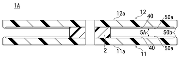
図5に示すように、テーパ状の軽量化部4を形成せず、第1及び第2フランジ部11、12の厚さを2mmとするとともに、リブ5Aの内側ガイド部50a及び外側ガイド部50bの高さをフランジ内側面40から0.1mmとした。このリール部材1Aは、従来のリール部材の構成のものである。
そして、第1及び第2フランジ部11、12の径を195mmとし、長さ300mの接着フィルム6を巻き取った。
図5に示すように、テーパ状の軽量化部4を形成せず、第1及び第2フランジ部11、12の厚さを2mmとするとともに、リブ5Aの内側ガイド部50a及び外側ガイド部50bの高さをフランジ内側面40から0.1mmとした。このリール部材1Aは、従来のリール部材の構成のものである。
そして、第1及び第2フランジ部11、12の径を195mmとし、長さ300mの接着フィルム6を巻き取った。
<比較例2>
図5に示す形状で第1及び第2フランジ部11、12の径が250mmのリール部材1Aを作成し、長さ500mの接着フィルム6を巻き取った。
図5に示す形状で第1及び第2フランジ部11、12の径が250mmのリール部材1Aを作成し、長さ500mの接着フィルム6を巻き取った。
<比較例3>
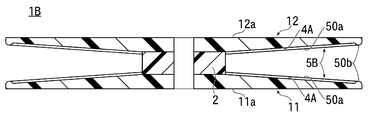
図6に示すように、第1及び第2フランジ部11、12の内側面にテーパ状の軽量化部4Aを形成する一方で、リブ5Bの内側ガイド部50a及び外側ガイド部50bの高さをフランジ内側面から0.1mmとした。
その他は実施例と同一の条件でリール部材1Bを作成し、長さ300mの接着フィルム6を巻き取った。
図6に示すように、第1及び第2フランジ部11、12の内側面にテーパ状の軽量化部4Aを形成する一方で、リブ5Bの内側ガイド部50a及び外側ガイド部50bの高さをフランジ内側面から0.1mmとした。
その他は実施例と同一の条件でリール部材1Bを作成し、長さ300mの接着フィルム6を巻き取った。
<比較例4>
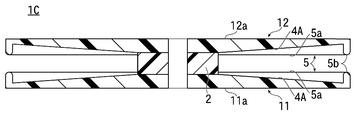
図7に示すように、補強部を設けずにテーパ状の軽量化部4Aを形成した以外は実施例と同一の条件でリール部材1Cを作成し、長さ500mの接着フィルム6を巻き取った。
図7に示すように、補強部を設けずにテーパ状の軽量化部4Aを形成した以外は実施例と同一の条件でリール部材1Cを作成し、長さ500mの接着フィルム6を巻き取った。
<評価>
実施例及び比較例1~4によって作成したリール部材(フィルム収容体)をそれぞれ24時間室温の環境下で放置し、フランジ外周部における第1及び第2フランジ部11、12間のクリアランスをレーザー反射式変位計を用いて測定した。その結果を表1に示す。
また、実施例及び比較例1~4において、巻取時の接着フィルム6の状態(脱落等)を目視で観察した。その結果を表1に示す。
実施例及び比較例1~4によって作成したリール部材(フィルム収容体)をそれぞれ24時間室温の環境下で放置し、フランジ外周部における第1及び第2フランジ部11、12間のクリアランスをレーザー反射式変位計を用いて測定した。その結果を表1に示す。
また、実施例及び比較例1~4において、巻取時の接着フィルム6の状態(脱落等)を目視で観察した。その結果を表1に示す。
さらに、接着フィルム6を、引出張力50g、引張速度500mm/秒で1秒間のインターバルをおいて1秒間の引き出しを、最後まで繰り返し行い、引出時及び引出後の接着フィルム6の状態(引出時の引っかかり、ブロッキング、切れ)を目視で観察した。その結果を表1に示す。

<評価結果>
表1から明らかなように、補強部及びテーパ状の軽量化部を設けていない比較例1、2の場合、接着フィルム6の長さが300mと短い場合(比較例1)には、フランジ外周部におけるクリアランスの狂いが小さく(1.15±0.1mm)、巻取時及び引出時において問題は生じなかったが、接着フィルム6の長さが500mと長尺化した場合(比較例2)には、フランジ外周部におけるクリアランスの狂いが大きくなるとともに(1.15±0.4mm)、引出時において、引っかかり、ブロッキング、切れが生じた。
表1から明らかなように、補強部及びテーパ状の軽量化部を設けていない比較例1、2の場合、接着フィルム6の長さが300mと短い場合(比較例1)には、フランジ外周部におけるクリアランスの狂いが小さく(1.15±0.1mm)、巻取時及び引出時において問題は生じなかったが、接着フィルム6の長さが500mと長尺化した場合(比較例2)には、フランジ外周部におけるクリアランスの狂いが大きくなるとともに(1.15±0.4mm)、引出時において、引っかかり、ブロッキング、切れが生じた。
また、第1及び第2フランジ部11、12の内側面にテーパ状の軽量化部4Aを形成する一方で、リブ5Bの高さをリール部材1Bの内側面から0.1mmとした比較例3においては、第1及び第2のフランジ部11、12の径が250mmの場合であっても、フランジ外周部におけるクリアランスの狂いが大きく(1.15±0.2mm)、しかも巻取時において接着フィルム6の巻きずれ及び脱落が生じた。
さらに、第1及び第2フランジ部11、12の内側面にテーパ状の軽量化部4Aを形成するとともに、フランジ外周部におけるリブ5の高さを実施例と同じ0.5mmにした比較例4では、接着フィルム6の長さを500mに長尺化することができたが、フランジ外周部におけるクリアランスの狂いが大きく(1.15±0.2mm)、しかも引出時において引っかかりが生じた。
これに対し、第1及び第2フランジ部11、12の内側面に補強部3及びテーパ状の軽量化部4を形成するとともに、フランジ外周部におけるリブ5の高さを0.5mmにした実施例では、接着フィルム6の長さを500mに長尺化した場合においても、フランジ外周部におけるクリアランスの狂いが小さく(1.15±0.1mm)、特に成型直後は、1.15±0.1mm以下であった。
さらに、実施例のものにおいては、巻取時及び引出時において何ら問題が生じなかった。
さらに、実施例のものにおいては、巻取時及び引出時において何ら問題が生じなかった。
以上の結果から、本発明によれば、リール部材の自重によるフランジ外周部のたわみを防止し、第1及び第2フランジ部間のクリアランスの精度を向上できることを実証することができた。
1…リール部材
2…巻芯軸部
3…補強部
4…軽量化部
5…リブ
5a…内側ガイド部
5b…外側ガイド部
6…接着フィルム
10…駆動軸
11…第1フランジ部
12…第2フランジ部
O…回転軸線
2…巻芯軸部
3…補強部
4…軽量化部
5…リブ
5a…内側ガイド部
5b…外側ガイド部
6…接着フィルム
10…駆動軸
11…第1フランジ部
12…第2フランジ部
O…回転軸線
Claims (5)
- 円筒形状に形成され、接着フィルムを巻取可能な巻芯軸部と、
前記巻芯軸部の両端部に設けられた第1及び第2フランジ部とを備え、
前記第1及び第2フランジ部の前記巻芯軸部の近傍に一定の厚さの補強部が設けられるとともに、
前記第1及び第2フランジ部の内側部分で、かつ、前記補強部に対してフランジ外周側の部分に、厚さが前記補強部の厚さより薄くなるように形成された軽量化部が設けられ、
さらに、前記第1及び第2フランジ部の内側部分に、当該接着フィルムを案内するためのリブが設けられているリール部材。 - 前記軽量化部が、前記補強部からフランジ外周部に向って厚さが薄くなるようにテーパ状に形成されている請求項1記載のリール部材。
- 前記リブは、当該接着フィルムを案内する面が、当該リール部材の回転方向に対して直交する面上に位置するように設けられている請求項1又は2のいずれか1項記載のリール部材。
- 円筒形状に形成され、接着フィルムを巻取可能な巻芯軸部と、前記巻芯軸部の両端部に設けられた第1及び第2フランジ部とを備え、前記第1及び第2フランジ部の前記巻芯軸部の近傍に一定の厚さの補強部が設けられるとともに、前記第1及び第2フランジ部の内側部分で、かつ、前記補強部に対してフランジ外周側の部分に、厚さが前記補強部の厚さより薄くなるように形成された軽量化部が設けられ、さらに、前記第1及び第2フランジ部の内側部分に、当該接着フィルムを案内するためのリブが設けられているリール部材と、
前記リール部材の巻芯軸部に巻き取られた接着フィルムとを有するフィルム収容体。 - 前記接着フィルムが、絶縁性接着剤中に導電性粒子が分散された異方導電性接着フィルムである請求項4記載のフィルム収容体。
Priority Applications (2)
| Application Number | Priority Date | Filing Date | Title |
|---|---|---|---|
| CN201280059947.9A CN103958384B (zh) | 2011-12-05 | 2012-11-29 | 卷盘部件和薄膜容纳体 |
| KR1020147018333A KR102004565B1 (ko) | 2011-12-05 | 2012-11-29 | 릴 부재 및 필름 수용체 |
Applications Claiming Priority (2)
| Application Number | Priority Date | Filing Date | Title |
|---|---|---|---|
| JP2011-266085 | 2011-12-05 | ||
| JP2011266085A JP5930274B2 (ja) | 2011-12-05 | 2011-12-05 | リール部材及びフィルム収容体 |
Publications (1)
| Publication Number | Publication Date |
|---|---|
| WO2013084797A1 true WO2013084797A1 (ja) | 2013-06-13 |
Family
ID=48574167
Family Applications (1)
| Application Number | Title | Priority Date | Filing Date |
|---|---|---|---|
| PCT/JP2012/080987 Ceased WO2013084797A1 (ja) | 2011-12-05 | 2012-11-29 | リール部材及びフィルム収容体 |
Country Status (5)
| Country | Link |
|---|---|
| JP (1) | JP5930274B2 (ja) |
| KR (1) | KR102004565B1 (ja) |
| CN (1) | CN103958384B (ja) |
| TW (1) | TWI649250B (ja) |
| WO (1) | WO2013084797A1 (ja) |
Cited By (4)
| Publication number | Priority date | Publication date | Assignee | Title |
|---|---|---|---|---|
| EP3438030A4 (en) * | 2016-03-31 | 2019-10-30 | Fujikura Ltd. | Coil for winding an optical fiber, method for winding an optical fiber and optical fiber wound on a coil |
| US20210269208A1 (en) * | 2018-07-18 | 2021-09-02 | Max Co., Ltd. | Binding tape, binding method, tape winding body and reel |
| US20230339720A1 (en) * | 2019-11-22 | 2023-10-26 | Dexerials Corporation | Reel member and adhesive film winding body |
| US12391445B2 (en) | 2018-07-18 | 2025-08-19 | Max Co., Ltd. | Binding tape, binding method, tape winding body and reel |
Families Citing this family (6)
| Publication number | Priority date | Publication date | Assignee | Title |
|---|---|---|---|---|
| JP3086743B2 (ja) | 1992-03-03 | 2000-09-11 | 鐘紡株式会社 | 半導体装置 |
| JP2015086029A (ja) * | 2013-10-29 | 2015-05-07 | デクセリアルズ株式会社 | リール部材及びフィルム収容体 |
| MY202618A (en) * | 2015-08-10 | 2024-05-10 | Dexerials Corp | Reel member, film housing body, and method for manufacturing reel member |
| KR101645335B1 (ko) * | 2016-03-14 | 2016-08-03 | 권창수 | 강도가 보강된 분리막 필름용 권취 코어 |
| TWI669262B (zh) * | 2019-01-21 | 2019-08-21 | 頎邦科技股份有限公司 | 防止捲輪的限位盤變形之限制裝置 |
| JP7480785B2 (ja) * | 2019-11-07 | 2024-05-10 | 住友電気工業株式会社 | 光ファイバの巻き取り装置および光ファイバの製造方法 |
Citations (4)
| Publication number | Priority date | Publication date | Assignee | Title |
|---|---|---|---|---|
| JPH0619182U (ja) * | 1991-12-19 | 1994-03-11 | ソニー株式会社 | テープリール |
| JP2001318451A (ja) * | 2000-03-03 | 2001-11-16 | Fuji Photo Film Co Ltd | アダプタ付き遮光性感光材料ロール及び感光材料用ロール駆動支持用アダプタ |
| WO2007148593A1 (ja) * | 2006-06-21 | 2007-12-27 | Hitachi Chemical Company, Ltd. | リール |
| JP2009274829A (ja) * | 2008-05-15 | 2009-11-26 | Gold Kogyo Kk | 物流用リール |
Family Cites Families (7)
| Publication number | Priority date | Publication date | Assignee | Title |
|---|---|---|---|---|
| GB802818A (en) * | 1955-08-29 | 1958-10-15 | Smith & Sons Ltd S | Improvements in or relating to methods of winding bobbins with wire |
| US6598825B2 (en) * | 1998-02-13 | 2003-07-29 | C. Robert Ripplinger | Simultaneous-access surfaces for reel-flange fasteners |
| US6435451B1 (en) * | 2000-10-19 | 2002-08-20 | Storage Technology Corporation | Compliant tape reel flanges |
| JP2002251859A (ja) * | 2000-12-19 | 2002-09-06 | Fuji Photo Film Co Ltd | テープリール |
| US7073742B2 (en) * | 2003-01-21 | 2006-07-11 | Quantum Corporation | Tape guiding reel |
| JP2007094662A (ja) | 2005-09-28 | 2007-04-12 | Hitachi Electronics Service Co Ltd | 機器特定システム及びidタグ |
| WO2011118503A1 (ja) * | 2010-03-23 | 2011-09-29 | 日立化成工業株式会社 | 接着テープ用リール |
-
2011
- 2011-12-05 JP JP2011266085A patent/JP5930274B2/ja active Active
-
2012
- 2012-11-29 WO PCT/JP2012/080987 patent/WO2013084797A1/ja not_active Ceased
- 2012-11-29 CN CN201280059947.9A patent/CN103958384B/zh active Active
- 2012-11-29 KR KR1020147018333A patent/KR102004565B1/ko active Active
- 2012-12-05 TW TW101145607A patent/TWI649250B/zh active
Patent Citations (4)
| Publication number | Priority date | Publication date | Assignee | Title |
|---|---|---|---|---|
| JPH0619182U (ja) * | 1991-12-19 | 1994-03-11 | ソニー株式会社 | テープリール |
| JP2001318451A (ja) * | 2000-03-03 | 2001-11-16 | Fuji Photo Film Co Ltd | アダプタ付き遮光性感光材料ロール及び感光材料用ロール駆動支持用アダプタ |
| WO2007148593A1 (ja) * | 2006-06-21 | 2007-12-27 | Hitachi Chemical Company, Ltd. | リール |
| JP2009274829A (ja) * | 2008-05-15 | 2009-11-26 | Gold Kogyo Kk | 物流用リール |
Cited By (7)
| Publication number | Priority date | Publication date | Assignee | Title |
|---|---|---|---|---|
| EP3438030A4 (en) * | 2016-03-31 | 2019-10-30 | Fujikura Ltd. | Coil for winding an optical fiber, method for winding an optical fiber and optical fiber wound on a coil |
| US10662022B2 (en) | 2016-03-31 | 2020-05-26 | Fujikura Ltd. | Optical fiber winding bobbin, optical fiber winding method, and bobbin-wound optical fiber |
| US20210269208A1 (en) * | 2018-07-18 | 2021-09-02 | Max Co., Ltd. | Binding tape, binding method, tape winding body and reel |
| US12378089B2 (en) * | 2018-07-18 | 2025-08-05 | Max Co., Ltd. | Binding tape, binding method, tape winding body and reel |
| US12391445B2 (en) | 2018-07-18 | 2025-08-19 | Max Co., Ltd. | Binding tape, binding method, tape winding body and reel |
| US20230339720A1 (en) * | 2019-11-22 | 2023-10-26 | Dexerials Corporation | Reel member and adhesive film winding body |
| US12441580B2 (en) * | 2019-11-22 | 2025-10-14 | Dexerials Corporation | Reel member and adhesive film winding body |
Also Published As
| Publication number | Publication date |
|---|---|
| TW201341293A (zh) | 2013-10-16 |
| TWI649250B (zh) | 2019-02-01 |
| KR102004565B1 (ko) | 2019-07-26 |
| CN103958384A (zh) | 2014-07-30 |
| JP2013116816A (ja) | 2013-06-13 |
| CN103958384B (zh) | 2016-04-13 |
| KR20140099314A (ko) | 2014-08-11 |
| JP5930274B2 (ja) | 2016-06-08 |
Similar Documents
| Publication | Publication Date | Title |
|---|---|---|
| JP5930274B2 (ja) | リール部材及びフィルム収容体 | |
| EP2368828A2 (en) | Reel | |
| EP2030937A1 (en) | Reel | |
| JP5905351B2 (ja) | リール部材及びフィルム収容体 | |
| JP6312380B2 (ja) | リール部材及びフィルム収容体並びにフィルム収容体の製造方法 | |
| TW202138277A (zh) | 捲盤構件、接著膜捲裝體 | |
| JP7545020B2 (ja) | 上刃ロール、スリット装置、スリット方法及び積層テープ | |
| US20160251195A1 (en) | Reel member and film accommodating body | |
| EP3438030A1 (en) | Bobbin for reeling optical fiber, method for reeling optical fiber, and optical fiber wound on bobbin | |
| US20220168916A1 (en) | Upper blade roller, slitting device, slitting method, and laminated tape | |
| CN104169200B (zh) | 粘接膜的贴附方法和粘接膜贴附装置 | |
| JP5770651B2 (ja) | リール部材及びフィルム収容体並びに接着フィルムの引出方法 | |
| KR101202043B1 (ko) | 이방 도전성 필름용 릴 및 이를 위한 지지클립 | |
| BR112021026587B1 (pt) | Bobina para enrolamento e desenrolamento de uma linha e processo de fabricação de uma bobina |
Legal Events
| Date | Code | Title | Description |
|---|---|---|---|
| 121 | Ep: the epo has been informed by wipo that ep was designated in this application |
Ref document number: 12855549 Country of ref document: EP Kind code of ref document: A1 |
|
| NENP | Non-entry into the national phase |
Ref country code: DE |
|
| ENP | Entry into the national phase |
Ref document number: 20147018333 Country of ref document: KR Kind code of ref document: A |
|
| 122 | Ep: pct application non-entry in european phase |
Ref document number: 12855549 Country of ref document: EP Kind code of ref document: A1 |