WO2013084780A1 - 撮像装置 - Google Patents
撮像装置 Download PDFInfo
- Publication number
- WO2013084780A1 WO2013084780A1 PCT/JP2012/080881 JP2012080881W WO2013084780A1 WO 2013084780 A1 WO2013084780 A1 WO 2013084780A1 JP 2012080881 W JP2012080881 W JP 2012080881W WO 2013084780 A1 WO2013084780 A1 WO 2013084780A1
- Authority
- WO
- WIPO (PCT)
- Prior art keywords
- subject
- frame
- image
- unit
- frame speed
- Prior art date
- Legal status (The legal status is an assumption and is not a legal conclusion. Google has not performed a legal analysis and makes no representation as to the accuracy of the status listed.)
- Ceased
Links
Images



Classifications
-
- G—PHYSICS
- G03—PHOTOGRAPHY; CINEMATOGRAPHY; ANALOGOUS TECHNIQUES USING WAVES OTHER THAN OPTICAL WAVES; ELECTROGRAPHY; HOLOGRAPHY
- G03B—APPARATUS OR ARRANGEMENTS FOR TAKING PHOTOGRAPHS OR FOR PROJECTING OR VIEWING THEM; APPARATUS OR ARRANGEMENTS EMPLOYING ANALOGOUS TECHNIQUES USING WAVES OTHER THAN OPTICAL WAVES; ACCESSORIES THEREFOR
- G03B7/00—Control of exposure by setting shutters, diaphragms or filters, separately or conjointly
- G03B7/08—Control effected solely on the basis of the response, to the intensity of the light received by the camera, of a built-in light-sensitive device
- G03B7/091—Digital circuits
-
- H—ELECTRICITY
- H04—ELECTRIC COMMUNICATION TECHNIQUE
- H04N—PICTORIAL COMMUNICATION, e.g. TELEVISION
- H04N23/00—Cameras or camera modules comprising electronic image sensors; Control thereof
- H04N23/60—Control of cameras or camera modules
Definitions
- the present invention relates to an imaging apparatus.
- Patent Document 1 A technique for detecting a preset movement of a subject and obtaining a plurality of still images expressing the movement is known (see Patent Document 1).
- the conventional technology has a problem that a number of similar images that do not change between frames are recorded.
- an imaging device monitors at a predetermined frame rate by an imaging device that images a subject image, an imaging optical system that forms the subject image on an imaging surface of the imaging device, and the imaging device.
- a live view image acquisition unit that acquires an image
- a subject extraction unit that extracts a subject from a monitor image
- a frame speed calculation unit that calculates a frame speed when continuously shooting the subject, and a plurality of still images according to shooting instructions
- a shooting unit that continuously shoots images, a control unit that controls the shooting unit to continuously shoot at the frame speed calculated by the frame speed calculation unit, and an image recording unit that records still images shot by the shooting unit on a recording medium
- the frame speed calculation unit calculates the frame speed when continuously shooting the subject based on the subject extracted by the subject extraction unit.
- a subject specifying unit that specifies the type of subject extracted by the subject extracting unit, and a storage unit that stores movement speed data corresponding to the type of subject.
- the frame speed calculation unit reads movement speed data corresponding to the type of subject specified by the subject specifying unit from the storage unit, and calculates a frame speed for continuous shooting based on the movement speed data. It is preferable.
- the subject specifying unit specifies whether the subject is a person or an animal.
- the subject specifying unit when the subject specifying unit is a person, the subject specifying unit specifies whether the subject is an adult, a child, or an infant, and is an animal. It is preferable to identify whether it is a dog or a cat.
- the storage unit stores one or a plurality of moving speed data corresponding to each of an adult, a child, an infant, a dog, or a cat. Preferably it is.
- movement information acquisition that acquires movement information of a subject image in a monitor image based on a change between the monitor images of the subject extracted by the subject extraction unit.
- the frame speed calculation unit preferably calculates a frame speed for continuous shooting based on movement information of the subject image in the monitor image acquired by the movement information acquisition unit.
- the change in the subject image between the monitor images of the subject extracted by the subject extraction unit changes in the horizontal direction or the vertical direction of the subject image between the monitor images. It is preferable that the amount of movement is.
- the change in the subject image between the monitor images of the subject extracted by the subject extraction unit is a change in the size of the subject image between the monitor images. It is preferable.
- the frame speed calculation unit shortens the shooting interval when the rate of change in the size of the subject image exceeds the upper limit value. When the rate of change in the size of the subject image exceeds the lower limit, it is preferable to increase the shooting interval.
- the frame speed calculation unit performs the following every time one frame is shot so that the change of the subject image maintains a predetermined value. It is preferable to determine a shooting interval until a frame is shot. According to the eleventh aspect of the present invention, in the imaging device according to the second aspect, it is preferable that the frame speed calculation unit decreases the frame speed as the value of the moving speed data is smaller. According to the twelfth aspect of the present invention, in the imaging device according to the seventh or eighth aspect, it is preferable that the frame speed is decreased as the change in the subject image is smaller.
- the frame speed calculation unit further includes shooting field angle information and subject distance in addition to the movement speed data or movement information. Based on the information, the frame speed for continuous shooting is calculated.
- the frame speed calculation unit decreases the frame speed as the shooting angle of view is wider.
- the frame speed calculation unit decreases the frame speed as the subject distance increases.
- the frame speed calculation unit recalculates the frame speed when the imaging angle of view changes during continuous shooting.
- the frame speed calculation unit calculates the frame speed again when the subject distance changes during continuous shooting.
- the imaging apparatus further includes a posture determination unit that determines whether the imaging device is a vertical position posture or a horizontal position posture, and a frame speed calculation unit It is preferable that the frame speed in the case of the horizontal position and posture is slower than that in the case where the image pickup apparatus is in the vertical position and posture.
- the storage member that sequentially stores the still images of the subject image captured by the imaging element at the frame speed
- the storage member It is preferable to include a control unit that controls the image recording unit so as to record a plurality of still images corresponding to the frame speed calculated by the frame speed calculation unit among the sequentially stored still images on a recording medium.
- continuous shooting can be performed so as to have an appropriate change between frames.
- FIG. 1 is a block diagram illustrating the configuration of a digital camera 1 according to the first embodiment of the invention.
- the photographing lens 11 forms a subject image on the imaging surface 12 a of the imaging element 12.
- the CPU 16 performs a known AF process in response to an automatic focus adjustment (AF) instruction, and moves a focusing lens (not shown) constituting the photographing lens 11 forward and backward in the optical axis direction (arrow direction in FIG. 1). Thereby, the focal position of the photographic lens 11 is automatically adjusted.
- the AF process is performed using, for example, a contrast method that adjusts the focal position based on the contrast of the subject image.
- the driving of the focusing lens (not shown) is performed by the lens driving unit 21 that receives an instruction from the CPU 16.
- the CPU 16 moves the zoom lens (not shown) constituting the photographing lens 11 forward and backward in the optical axis direction when an operation signal is inputted from a zoom switch (not shown) constituting the operation member 20 described later. As a result, the shooting angle of view is adjusted.
- the zoom lens (not shown) is also driven by the lens driving unit 21 that receives an instruction from the CPU 16.
- the image sensor 12 is configured by a CMOS image sensor or the like.
- the image sensor 12 photoelectrically converts a subject image formed on the imaging surface 12a into an analog image signal.
- the analog image signal output from the image sensor 12 is converted into digital data by the A / D converter 13.
- the image processing unit 14 performs predetermined image processing on the digital data to generate image data for storage.
- the liquid crystal monitor 15 displays images and operation menu screens according to instructions from the CPU 16.
- a touch operation member 15 a is laminated on the display surface of the liquid crystal monitor 15.
- the touch operation member 15 a generates a signal indicating the touch position on the display screen of the liquid crystal monitor 15 touched by the user and sends the signal to the CPU 16.
- the nonvolatile memory 17 stores programs executed by the CPU 16, data necessary for execution processing, and the like.
- the contents of programs and data stored in the nonvolatile memory 17 can be added and changed by instructions from the CPU 16.
- the CPU 16 executes a control program using the buffer memory 18 as a work area, for example, and performs various controls on each part of the camera.
- the buffer memory 18 is also used when temporarily storing digital data.
- image data before, during, and after image processing by the image processing unit 14 is temporarily stored.
- the image processing unit 14 generates an image file (for example, an “Exif” file) in a predetermined format in which image data is stored, in addition to image processing on digital data.
- the recording / reproducing unit 19 records an image file on the memory card 50 based on an instruction from the CPU 16 and reads out the image file recorded on the memory card 50.
- the memory card 50 is a recording medium that is detachably attached to a card slot (not shown).
- the CPU 16 reproduces and displays the captured image on the liquid crystal monitor 15 based on the image file read from the memory card 50 by the recording / reproducing unit 19.
- the operation member 20 includes a half-press switch 20a that is turned on when the shutter button (not shown) is half-pressed, a full-press switch 20b that is turned on when the shutter button is fully pressed, a movie shooting switch, and a mode switch.
- the operation signal accompanying operation of each member is sent to CPU16.
- the ON signal (half-press operation signal) from the half-press switch 20a is output when the shutter button is pressed down to about half of the normal stroke, and the output is canceled when the half-stroke press-down operation is released.
- the ON signal (full push operation signal) from the full push switch 20b is output when the shutter button is pushed down to the normal stroke, and the output is released when the push operation of the normal stroke is released.
- the lens driving circuit 21 drives a focus adjustment motor (not shown) for driving the focusing lens (not shown) and a zoom adjustment motor (not shown) for driving the zoom lens (not shown).
- a circuit for driving A circuit for driving).
- the speaker driving circuit 22 generates an analog audio reproduction signal such as a reproduction sound, an operation sound, and an audio message based on the digital audio data sent from the CPU 16.
- the speaker 23 performs audio reproduction based on the audio reproduction signal.
- the audio processing circuit 24 amplifies the audio signal collected by the microphone 25 and converts the amplified signal into digital audio data by an A / D conversion circuit (not shown). Digital audio data is recorded on the memory card 50 in association with the image file.
- the attitude sensor 26 detects the direction of gravity, for example, and sends a detection signal to the CPU 16.
- the CPU 16 determines the shooting posture of the digital camera 1 based on the detection signal.
- the CPU 16 determines whether the digital camera 1 is upside down as well as the vertical position and horizontal position.
- the CPU 16, the nonvolatile memory 17, the buffer memory 18, the recording / playback unit 19, the image processing unit 14, the liquid crystal monitor 15, the speaker driving circuit 22, and the audio processing circuit 24 are connected via a bus 27.
- the above-described digital camera 1 is configured so that the “single shooting mode”, the “continuous shooting mode”, and the “moving mode” can be alternatively switched, for example, by the mode switch.
- the “single shooting mode” is a mode in which an image of one frame is acquired in response to the full-press operation signal, and still image data generated based on the acquired image is recorded in the memory card 50.
- an image of one frame is acquired in response to the full-press operation signal, and when the full-press operation signal is continuously input, further images of the next frame are continuously acquired.
- this mode multiple frames are taken continuously. Still image data generated based on the image of each frame is recorded in the memory card 50, respectively.
- a plurality of frames of images are acquired in response to an operation signal from the moving image shooting switch (not shown), and moving image data generated based on the images of the plurality of frames is recorded in the memory card 50.
- moving image shooting switch not shown
- the live view image is a monitor image acquired at a predetermined frame rate (for example, 30 fps) by the image pickup device 12 before a shooting instruction.
- “automatic frame speed continuous shooting” and “manual frame speed continuous shooting” can be switched by a user operation in “continuous shooting mode”. Switching between “auto frame speed continuous shooting” and “manual frame speed continuous shooting” is performed by a user through a menu operation, for example.
- Auto frame speed continuous shooting refers to continuous shooting in which the CPU 16 automatically changes the continuous shooting frame speed within a predetermined range (for example, between 10 frames / second and 0.5 frames / second).
- “Manual frame-speed continuous shooting” refers to continuous shooting in which a fixed frame-speed is set by a user operation.
- Auto frame speed continuous shooting 1 Since the first embodiment is characterized by “auto-frame speed continuous shooting”, the following description will be focused on “auto-frame speed continuous shooting 1”.
- the purpose of providing “auto frame speed continuous shooting” is to change the frame speed in accordance with the movement of the subject in continuous shooting. That is, the object is to set a fast continuous shooting frame speed for a fast-moving subject, and to set a slow continuous shooting frame number for a slow-moving subject. For this reason, the CPU 16 shortens the time between frames for a fast-moving subject, and continuously shoots at a low speed by increasing the time between frames for a slow-moving subject. Controls the continuous shooting frame speed.
- step S11 in FIG. 2 the CPU 16 performs “continuous shooting” of a subject moving at a low speed (small movement) and “sport” shooting a subject moving at a high speed (large movement).
- An operation for selecting one of the modes is accepted. This selection operation is performed, for example, by a user through a menu operation.
- step S ⁇ b> 12 the CPU 16 determines the angle of view ⁇ based on the focal length f of the photographing lens 11.
- the frame size of the imaging surface of the imaging device 12 is S (mm)
- the following equation (1) is established.
- S / 2 f ⁇ tan ( ⁇ / 2) (1)
- f is a focal length (mm).
- the CPU 16 obtains the focal length f based on the information indicating the zoom lens position acquired from the lens driving circuit 21, and substitutes the frame size S and the focal length f of the image sensor 12 into the above equation (1) to obtain the angle of view ⁇ .
- Ask. Data indicating the relationship between the zoom lens position and the focal length f is stored in the nonvolatile memory 17 in advance.
- the angle of view ⁇ h in the horizontal direction and the angle of view ⁇ v in the vertical direction are each expressed in units (deg).
- the CPU 16 that has determined the angle of view ⁇ h and ⁇ v waits for an AF process activation instruction while displaying the above-described live view image on the liquid crystal monitor 15.
- the CPU 16 further performs exposure control so as to obtain a proper exposure while performing a predetermined exposure calculation based on the data value of the live view image.
- step S13 in FIG. 2 for example, when the half-press switch 20a is turned on, the CPU 16 performs AF processing and proceeds to step S14.
- the CPU 16 obtains a subject distance D (m) from the digital camera 1 to the subject to be subjected to focus adjustment based on information indicating the focusing lens position acquired from the lens driving circuit 21. Data indicating the relationship between the focusing lens position and the subject distance D (m) is stored in advance in the nonvolatile memory 17.
- step S14 the CPU 16 sets the moving speed a of the subject. Details of the processing for setting the moving speed a will be described with reference to the flowchart illustrated in FIG.
- step S51 in FIG. 4 the CPU 16 determines whether the posture is the horizontal position or the vertical position based on the detection signal from the posture sensor 26, and proceeds to step S52.
- step S52 the CPU 16 determines whether or not a “face” of a person has been detected from the latest live view image.
- the CPU 16 detects a “face” region from the live view image by performing a known face detection process, the CPU 16 makes a positive determination in step S52 and proceeds to step S53. If the CPU 16 does not detect the “face” area of the person from the live view image, the CPU 16 makes a negative determination in step S52 and proceeds to step S55.
- step S53 the CPU 16 determines whether the detected “face” is an adult, a child (elementary school student), or an infant, and proceeds to step S54. Since the discrimination process for adults / children / infants is known, detailed description of the discrimination process is omitted.
- step S55 which proceeds after making a negative determination in step S52, the CPU 16 makes a positive determination in step S55 when it detects “dog” or “cat” from the live view image by performing a known pet detection process, and performs step S54. Proceed to When neither “dog” nor “cat” is detected from the live view image, the CPU 16 makes a negative determination in step S55 and proceeds to step S56.
- step S56 the CPU 16 performs default settings and proceeds to step S54.
- step S54 the CPU 16 sets the moving speed a as illustrated in FIG. 5 based on the determination result based on “face”, the detection result of “dog” or “cat”, and the default setting result, and the process shown in FIG. And the process proceeds to step S15 in FIG. FIG. 5 shows typical moving speeds (m / sec) of adults, children (elementary school students), infants, dogs and cats.
- the value of the moving speed “a” illustrated in FIG. 5 is stored in the nonvolatile memory 17 in advance.
- the “normal” mode and the “sport” mode correspond to the modes selected based on the user operation in step S11 (FIG. 2), respectively.
- the moving speed (m / sec) in the “normal” mode corresponds to the speed at which an adult, a child (elementary school student), and an infant walk.
- the moving speed (m / sec) in the “sport” mode corresponds to the speed at which an adult and a child (elementary school student) run.
- the infant's walking speed and running speed are not distinguished. That is, the moving speed is the same regardless of the “normal” mode and the “sport” mode.
- the value of the moving speed a in the default setting is, for example, 0.5 (m / sec) in the “normal” mode and 2.0 (m / sec) in the “sport” mode. Since the movement speed a by default setting is provided separately in the “normal” mode and the “sport” mode, the user operation is reflected even when the movement speed of the subject is not set based on face detection or pet detection. Default values can be used.
- the CPU 16 When detecting “Dog” and “Cat”, the CPU 16 sets a moving speed (10 m / sec) faster than that of a person regardless of whether the mode is “Normal” mode or “Sport” mode. Since it is difficult to understand only by the second speed, the minute speed is also shown in FIG.
- step S15 the CPU 16 determines the continuous shooting frame speed X (frame / second) based on the following equations (2) to (4), and proceeds to step S16.
- the meaning of the following equation (2) is to calculate the continuous shooting frame speed X so that a subject image moving in the horizontal direction is shot approximately 10 frames while moving from one end of the shooting screen to the other end. .
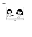
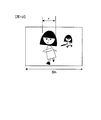
- FIG. 6 is a diagram illustrating a shooting screen in the case of the horizontal position and posture.
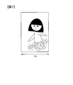
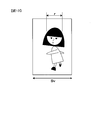
- FIG. 7 is a diagram illustrating a shooting screen in the case of the vertical position and posture.
- the shooting range Lh (m) for the horizontal position and posture is obtained by the following equation (3), and the shooting range Lv (m) for the vertical position and posture is obtained by the following equation (4).
- FIG. 8 is a diagram illustrating the relationship between the calculation result described above and the continuous shooting frame speed X determined by the CPU 16.
- step S16 the CPU 16 performs a photographing process. Specifically, continuous shooting is performed at the continuous frame speed X (frame / second) illustrated in FIG. 8 while the shooting instruction is performed, that is, while the full-press switch 20b is turned on.
- the shutter speed and the aperture value for example, values determined by exposure calculation based on the data of the latest live view image are used.
- the full-press switch 20b is turned off, the CPU 16 records still image data generated based on the acquired image of each frame on the memory card 50 without performing new imaging, and ends the processing in FIG.
- the digital camera 1 has an image sensor 12 that continuously shoots still images of a plurality of frames at a predetermined continuous shooting frame speed X according to a shooting instruction, a shooting range Lh (Lv), a subject distance D, and “normal”.
- the CPU 16 decreases the continuous shooting frame speed X as the photographing range Lh (Lv) is wider, so that the subject image changes moderately between frames. Can be taken continuously.
- the CPU 16 slows down the continuous shooting frame speed X as the subject distance D increases, so that continuous shooting is performed so that the subject image changes appropriately between frames. You can shoot.
- the digital camera 1 of the above (1) to (4) has an image sensor 12 that images a subject and outputs image data, and the CPU 16 is based on the face of a person detected based on the image data. Then, it is determined whether the person is an adult, a child, or an infant, and the continuous shooting frame speed is set according to the result. Thereby, for example, in the case of a child, continuous shooting can be performed so that the subject image changes moderately between frames by, for example, lowering the continuous shooting frame speed than that of an adult.
- the CPU 16 detects the frame when a human face is detected as compared to the frame speed when a dog or cat is detected based on the image data. Set faster than speed. As a result, even when shooting a dog or cat that moves faster than a person, it is possible to perform continuous shooting so that the subject image does not change too much between frames and changes appropriately.
- the digital camera 1 of the above (1) to (6) further includes a posture sensor 26 and a CPU 16 for determining whether the posture is a vertical position or a horizontal position.
- the CPU 16 compares the frame speed in the vertical position and posture with each other. Set the continuous shooting frame speed in the horizontal position and posture slower. Thereby, continuous shooting can be performed so that a moderate change can be obtained between frames.
- the CPU 16 uses the movement speed value designated in advance in each case of the “normal” mode or the “sport” mode. With such a configuration, continuous shooting can be realized so that a moderate change can be obtained between frames.
- the CPU 16 differs step by step based on the shooting range Lh (Lv), the subject distance D, and the “normal” mode or the “sport” mode. Since the continuous shooting frame speed is set, the configuration of the continuous shooting control can be simplified as compared with the case of fine control in multiple stages.
- Modification 1 In the first embodiment described above, an example in which continuous shooting ends when the release button full-press operation is completed has been described, but in addition to this, even when the subject moves and moves off the shooting screen, it is automatically performed. Alternatively, the continuous shooting may be terminated.
- the CPU 16 performs a known subject tracking process on the latest frame image acquired by continuous shooting, and ends the continuous shooting when the main subject to be tracked is not detected from the latest frame image. .
- Modification 2 In the first modification, when the continuous shooting is terminated because the subject has moved away from the shooting screen, the main subject is captured again while the release button is fully pressed even after the continuous shooting is completed. When it comes to be included in the screen, the continuous shooting that has ended may be resumed. In this case, for example, the CPU 16 restarts continuous shooting when the same “face” as the tracked “face” is included in the shooting screen again.
- the continuous shooting frame speed X may be newly calculated.
- the CPU 16 can determine the continuous shooting frame speed X based on the latest focal length information and subject distance information.
- a lamp (not shown) blinks, a warning sound is generated from the speaker 23, etc., so that the focal length f or the subject distance D is determined during continuous shooting.
- the user may be notified of the change. In this case, for example, the user can newly redo continuous shooting.
- the digital camera 1 that performs live view display has been described as an example, the present invention can also be applied to a camera that does not perform live view display at a normal time, such as a single-lens reflex camera.
- a camera that does not perform live view display at a normal time such as a single-lens reflex camera.
- “dog” or “cat” is detected based on the image acquired by the photometric image sensor.
- the image pickup device 12 acquires images at the continuous shooting frame speed X (frame / second) determined by the CPU 16, and the images are generated based on the images of the respective frames.
- An example in which still image data is recorded on the memory card 50 has been described. Instead of this, an image captured by the image sensor 12 may be temporarily buffered in the buffer memory 18 and an image of a predetermined frame in the buffer memory 18 may be recorded in the memory card 50 as still image data.
- the image sensor 12 continuously acquires images at a predetermined frame speed (for example, 10 frames / second), and sequentially buffers the acquired plurality of frame images in the buffer memory 18 (in time series). Keep it.
- the CPU 16 determines the continuous shooting frame speed X (frame / second) for recording, extracts a frame image corresponding to the determined frame speed X from the images in the buffer memory 18, and extracts still image data. Is recorded in the memory card 50.
- the determined continuous shooting frame speed X (frame / second) for recording is 10 frames / second
- the images of all frames accumulated in time series in the buffer memory 18 are recorded in the memory card 50 and determined.
- the continuous shooting frame speed X (frame / second) for recording is 5 frames / second
- images stored in time series in the buffer memory 18 are read every other frame and recorded on the memory card 50.
- the determined continuous shooting frame speed X (frame / second) for recording is 3 frames / second, images stored in time series in the buffer memory 18 are read every two frames and transferred to the memory card 50.
- Modification 8 Although the digital camera 1 has been described as an example, the present invention may be applied to an electronic device such as a mobile phone or a tablet terminal as long as it has a continuous shooting function.
- FIG. 1 is a block diagram illustrating the configuration of a digital camera 2 according to the second embodiment of the invention. Since the components of the digital camera 2 and their functions are basically the same as those of the digital camera 1, the description of each component and their functions is omitted.
- the shooting mode is basically the same as that of the digital camera 1. That is, the “single shooting mode”, the “continuous shooting mode”, and the “movie shooting mode” can be selectively switched by the mode switch, and in the “continuous shooting mode”
- the “auto frame speed continuous shooting” and the “manual frame speed continuous shooting” can be switched by a user operation.
- the switching between “automatic frame speed continuous shooting” and “manual frame speed continuous shooting” is also performed by the user through a menu operation, for example, as in the digital camera 1.
- Auto frame speed continuous shooting 2 Since the second embodiment is also characterized by “auto frame speed continuous shooting”, the following description will be focused on “auto frame speed continuous shooting 2”.
- the purpose of providing “auto frame speed continuous shooting 2” is to change the frame speed in response to a change in the movement of the subject when shooting continuously. That is, the object is to increase the continuous shooting frame speed when the movement of the subject becomes fast, and to reduce the number of continuous shooting frames when the movement of the object becomes slow. For this reason, the CPU 16 shortens the time between frames when the subject's movement becomes fast, and continuously shoots at high speed. If the subject's movement becomes slow, the CPU 16 lengthens the time between frames and continues at low speed. Controls the continuous frame speed so that it can be shot.
- the CPU 16 executes “auto frame speed continuous shooting 2” when the user has switched to “auto frame speed continuous shooting”.
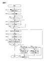
- the processing flow of “auto frame speed continuous shooting 2” will be described with reference to the flowchart illustrated in FIG. 9.
- the CPU 16 switches the shooting mode to “continuous shooting mode” and starts displaying the live view image on the liquid crystal monitor 15.
- a monitor image acquired at a predetermined frame rate (for example, 30 fps) by the image sensor 12 is displayed.
- step S21 of FIG. 9 the CPU 16 accepts an operation for selecting one of the “normal” mode and the “sport” mode. This selection operation is performed, for example, by a user through a menu operation. When the “sport” mode is selected, the CPU 16 performs control so as to set a faster continuous frame speed than in the “normal” mode.
- the CPU 16 causes the liquid crystal monitor 15 to start displaying a live view image in step S22 of FIG.
- the live view image is a monitor image acquired at a predetermined frame rate (for example, 30 fps) by the image pickup device 12 before a shooting instruction.
- the CPU 16 waits for an AF processing activation instruction while displaying the live view image on the liquid crystal monitor 15.
- the CPU 16 further performs exposure control so as to obtain a proper exposure while performing a predetermined exposure calculation based on the data value of the live view image.
- step S23 the CPU 16 determines whether or not the half-press switch 20a is turned on.
- the CPU 16 makes a positive determination in step S23 and proceeds to step S24. If the half-press operation signal is not input, the CPU 16 makes a negative determination in step S23 and repeats the determination process.
- step S24 the CPU 16 performs AF processing and proceeds to step S25.
- step S25 the CPU 16 after the AF process obtains the subject distance L from the digital camera 2 to the main subject that is the focus adjustment target based on the information indicating the focusing lens position acquired from the lens driving circuit 21. Data indicating the relationship between the focusing lens position and the subject distance L (m) is stored in advance in the nonvolatile memory 17.
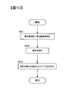
- the CPU 16 further extracts a subject on the imaging surface 12a of the imaging device 12 using the live view image, and obtains the position and size of the subject image on the monitor screen. Details of the processing for obtaining the position and size of the subject image will be described with reference to the flowchart illustrated in FIG. In step S61 of FIG. 10, the CPU 16 determines whether the posture is the horizontal position or the vertical position based on the detection signal from the posture sensor 26, and proceeds to step S62.
- step S62 the CPU 16 performs a process of extracting a subject from the live view image and proceeds to step S63.
- the subject extraction process is performed, for example, by detecting an edge surrounding a region that is a focus adjustment target or by detecting a region having a luminance or color common to the subject region that is a focus adjustment target.
- FIG. 11 is a diagram illustrating a case where a railway vehicle is extracted as a subject.
- step S63 the CPU 16 obtains the position p and the size r of the subject image that the extracted subject area occupies in the imaging surface 12a of the imaging device 12 in the imaging surface 12a of the imaging device 12 described above.
- the position of the subject image is obtained based on, for example, the pixel position of the image sensor corresponding to the horizontal and vertical center positions of the subject area occupying the imaging surface 12a of the image sensor 12.
- the size of the subject image is obtained based on, for example, the number of pixels in the horizontal direction and / or the vertical direction of the subject region occupying the imaging surface 12a of the imaging element 12.
- step S26 the CPU 16 determines whether or not the full push switch 20b is turned on. When the full-press operation signal is input, the CPU 16 makes a positive determination in step S26 and proceeds to step S27. If the full-press operation signal is not input, the CPU 16 makes a negative determination in step S26, returns to step S24, and repeats the above-described processing.
- step S27 the CPU 16 performs AF processing again and proceeds to step S28.
- step S28 the CPU 16 shoots one frame in step S28 and proceeds to step S29.
- step S29 the CPU 16 obtains the position p and size r of the subject image as in step S63, and adjusts the focus from the digital camera 2 based on the information indicating the focusing lens position acquired from the lens driving circuit 21.
- the subject distance L to the main subject that is the target of is obtained, and the process proceeds to step S30.
- step S30 the CPU 16 determines the frame speed X to be employed based on the frame interval ⁇ t1 between the most recent frame image and the previous frame image, the change amount ⁇ p of the subject image position, and the change amount ⁇ r of the subject image size r. (Frame / second) or a waiting time until shooting of the next frame, that is, a frame interval ⁇ t2 (second) is calculated.
- the full-press operation is performed from the imaging timing of the live view image immediately before the full-press operation (S26).
- the time until the imaging timing of the first frame after is set to ⁇ t1.
- the horizontal subject image position ph and the vertical position pv in the live view image immediately before the full press operation (S26) and the horizontal subject image position ph and the vertical direction position pv in the photographed image of the first frame after the full press operation (S26). are the difference ⁇ ph and ⁇ pv, respectively.
- the difference ⁇ r is the difference between the subject image size r in the live view image immediately before the full press operation (S26) and the subject image size r in the first frame taken after the full press operation (S26).
- the frame speed or the frame interval can be set so that the change of the subject image in the monitor image is constant.
- the frame size Sv (mm) in the vertical position is 1/2.
- the time required to move is obtained by Sv ⁇ ⁇ t1 / 2 ⁇ pv.
- the CPU 16 employs the frame speed having the larger value among the expressions (5) and (7) as the frame speed X (frame / second). Or CPU16 employ
- the setting of the frame speed X (frame / second) when the subject moves in the front-rear direction and the frame interval ⁇ t2 (second) in that case will be described.
- the full-press operation is performed from the imaging timing of the live view image immediately before the full-press operation (S26).
- S26 The time until the imaging timing of the first frame after is set to ⁇ t1.
- the difference between the subject image size r in the live view image immediately before the full press operation (S26) and the subject image size r in the first shot image after the full press operation (S26) is defined as a change amount ⁇ r.
- the frame size in the case of the horizontal position and posture uses Sh (mm), and in the case of the vertical position and posture, the frame size in the case of the vertical position and posture is Sv (mm). Use.
- the shooting interval until the next frame is determined so that the change amount ⁇ r with respect to the frame size S is a predetermined ratio.
- the smaller the change amount ⁇ r the wider the shooting interval (the continuous shooting speed becomes slower), and the larger the change amount ⁇ r, the closer the shooting interval becomes to the upper limit value (the continuous shooting speed becomes faster).
- the frame size S is different between the horizontal position and the vertical position.
- FIG. 12 is a diagram illustrating a shooting screen in the case of the horizontal position and posture.
- the subject image size r is obtained for the main subject that is the target of focus adjustment.
- FIG. 13 is a diagram illustrating a shooting screen in the case of the vertical position and posture. Also in this case, the subject image size r is obtained for the main subject that is the subject of focus adjustment.
- step S31 of FIG. 9 the CPU 16 determines whether or not the full push switch 20b is continuously turned on. If the full-press operation signal is continued, the CPU 16 makes an affirmative decision in step S31 and proceeds to step S32. If the full-press operation signal is not input, the CPU 16 makes a negative determination in step S31. If a negative determination is made, continuous shooting is terminated.
- step S32 the CPU 16 determines whether or not the change degree of the subject image on the imaging surface 12a is greater than a predetermined value on the larger side.
- the CPU 16 makes a positive determination in step S32 and proceeds to step S33. If the change amount ⁇ r obtained in step S30 is equal to or less than the predetermined value on the larger side, the CPU 16 makes a negative determination in step S32 and proceeds to step S34.
- step S33 the CPU 16 controls the time ⁇ t2 so that the frame interval (time t) at the time of continuous shooting is made shorter than the frame interval at the time of previous frame shooting, or the frame speed X (frame / frame). Second) is changed to a larger value, and the process proceeds to step S36.
- step S34 the CPU 16 determines whether or not the change degree of the subject image on the imaging surface 12a is smaller than a predetermined value on the smaller side. If the change amount ⁇ r of the subject image size r obtained in step S30 is smaller than the predetermined value on the smaller side, the CPU 16 makes a positive determination in step S34 and proceeds to step S35. If the change amount ⁇ r obtained in step S30 is greater than or equal to the predetermined value on the smaller side, the CPU 16 makes a negative determination in step S34 and proceeds to step S36.
- step S35 the CPU 16 controls the time ⁇ t2 so that the frame interval (time t) at the time of continuous shooting is longer than the frame interval at the time of previous frame shooting, or the frame speed X (frame / frame). Second) is changed to a smaller value, and the process proceeds to step S36.
- step S36 the CPU 16 counts the time ⁇ t2 and returns to step S27, and repeats the above-described processing or repeats photographing at a newly set frame speed.
- the continuous shooting of the next frame is performed at the frame interval t2, or the continuous shooting is performed at the frame speed X.
- the CPU 16 sets the time from the imaging timing of the previous frame to the imaging timing of the previous frame as the frame interval. The above calculation is performed with ⁇ tn, and the difference ⁇ r between the subject image size r in the previous frame shot image and the subject image size r in the previous frame shot image.
- the shooting instruction is performed, that is, while the full-press switch 20b is turned on, continuous shooting is performed at the frame speed calculated based on the degree of change of the subject image on the imaging surface 12a.
- the CPU 16 records still image data generated based on each acquired frame image on the memory card 50 without performing new imaging.
- the digital camera 2 determines the frame speed of continuous shooting based on the image sensor 12 that continuously shoots still images of a plurality of frames in accordance with the shooting instruction and the movement amount of the subject image with respect to the frame size Sh (Sv). And a CPU 16 that controls the image sensor 12 so as to continuously shoot at the frame speed determined by the CPU 16, so that an appropriate change is made between frames of the continuous shot image according to the moving speed of the subject. Continuous shooting can be performed so that
- the digital camera 2 uses the image sensor 12 that continuously shoots still images of a plurality of frames according to a shooting instruction, and the frame speed of continuous shooting based on the amount of change in the subject image size with respect to the frame size Sh (Sv) And the CPU 16 that controls the image sensor 12 so that continuous shooting is performed at the frame speed determined by the CPU 16, and is appropriately performed between frames of the continuous shot image according to the moving speed of the subject. Continuous shooting can be performed so as to have various changes.
- the CPU 16 reduces the frame speed as the moving speed of the subject image decreases with respect to a predetermined upper frame speed (for example, 10 frames / second). Can be taken continuously.
- a predetermined upper frame speed for example, 10 frames / second.
- the CPU 16 reduces the frame speed as the change amount of the subject image size is smaller with respect to a predetermined upper frame speed (for example, 10 frames / second). Can be taken continuously.
- a predetermined upper frame speed for example, 10 frames / second.
- the CPU 16 determines the shooting interval for each frame so that the moving speed of the subject image with respect to the frame size Sh (Sv) is a predetermined size. Continuous shooting can be performed so that a moderate change can be obtained between frames.
- the CPU 16 determines the shooting interval for each frame so that the subject image size change with respect to the frame size Sh (Sv) is a predetermined ratio. Continuous shooting can be performed so that moderate changes can be obtained.
- the CPU 16 makes the frame speed faster than the previous frame when the change in the movement speed of the subject image exceeds a predetermined value. Continuous shooting can be performed so that a moderate change can be obtained between frames.
- the CPU 16 increases the frame speed faster than the previous frame when the amount of change in the subject image size exceeds a predetermined value. On the other hand, continuous shooting can be performed so that a moderate change can be obtained between frames.
- the digital camera 2 of (1) to (5) further includes a posture sensor 26 and a CPU 16 for determining whether the posture is a vertical position or a horizontal position, and the CPU 16 has a horizontal frame size in the determined position. Since the frame speed is determined based on the change amount of the moving speed of the subject image or the change amount of the subject image size r with respect to Sh (Sv), it is possible to obtain a moderate change between the frames in both the vertical position and the horizontal position. Can be taken continuously.
- the frame interval ⁇ t2 is set based on the relationship between the size (frame size) of the imaging surface 12a of the imaging device 12 and the amount of change in the subject image size of the subject image on the imaging surface 12a of the imaging device 12. Calculated. However, when calculating the frame interval ⁇ t2, the angle of view ⁇ obtained based on the relationship between the focal length f of the imaging optical system 11 and the angle of view ⁇ , the subject distance L obtained immediately before the full press operation (S26), and the total distance The frame interval ⁇ t2 may be calculated by using ⁇ L as the difference from the subject distance L obtained at the time of shooting the first frame after the pressing operation (S26). In this case, the frame interval ⁇ t2 is calculated according to the following procedure.
- CPU16 determines the angle of view (alpha) based on the focal distance f of the imaging optical system 11 after completion
- the procedure for determining the angle of view ⁇ is the same as the procedure described in the first embodiment.
- the relationship between the focal length f (mm) and the angle of view ⁇ is as illustrated in FIG.
- the CPU 16 calculates the time ⁇ t2 by the following equation (11) in the following equation (9) in the sport mode and in the following equation (10) in the normal mode.
- the symbol f is the focal length of the imaging optical system 11.
- the symbol ⁇ corresponds to the angle of view of Expression (1).
- ⁇ t2 ⁇ r ⁇ ⁇ t1 / (2 ⁇ tan ( ⁇ / 2) ⁇ ⁇ L) (13)
- the meaning of the above expression (11) means that the amount of change ⁇ r of the subject image size r on the imaging surface 12a of the subject coming (or moving away) toward the camera direction corresponds to the frame size S (horizontal direction) of the imaging surface 12a.
- the continuous shooting frame speed is calculated so that approximately 10 frames are captured during the period.
- the above equation (10) means that the amount of change ⁇ r of the subject image size r on the imaging surface 12a of the subject that moves toward (or moves away from) the camera is equivalent to the frame size S (horizontal direction) of the imaging surface 12a.
- the continuous shooting frame speed is calculated so that approximately five frames are shot in the meantime.
- the value of the above equation (3) may be set as appropriate.
- the continuous frame speed may be calculated so that eight frames are shot in the sport mode and three frames are shot in the normal mode.
- the processing may be repeated by returning to step S23.
- the CPU 16 can determine the continuous shooting frame speed based on the latest focal length information and subject distance information.
- the user notices that the focal length f has changed during continuous shooting by blinking a lamp (not shown) or generating a warning sound from the speaker 23. You may make it inform. In this case, for example, the user can newly perform continuous shooting again.
- Step S21 An example has been described. Instead of such setting, the CPU 16 may automatically switch based on the degree of change of the subject image on the imaging surface 12a. The degree of change in the subject image may be determined from the moving speed and the amount of change in the size of the subject image. At this time, the movement of the subject in the front-rear direction may be determined based on the amount of change in the subject distance.
- Modification 14 Although the digital camera 2 that performs live view display has been described as an example, the present invention can also be applied to a camera that does not perform live view display at a normal time, such as a single-lens reflex camera. In this case, for example, the subject is extracted based on the image acquired by the photometric image sensor.
- the image pickup device 12 acquires images at the continuous frame speed (frame interval) determined by the CPU 16, and the images are generated based on the images of the respective frames.
- An example in which still image data is recorded on the memory card 50 has been described. Instead of this, an image captured by the image sensor 12 may be temporarily buffered in the buffer memory 18 and an image of a predetermined frame in the buffer memory 18 may be recorded in the memory card 50 as still image data.
- the image sensor 12 continuously acquires images at a predetermined frame speed (for example, 10 frames / second), and sequentially buffers the acquired plurality of frame images in the buffer memory 18 (in time series). Keep it.
- the CPU 16 determines the continuous shooting frame interval for recording as described above, extracts a frame image corresponding to the determined frame interval from the images in the buffer memory 18, and records still image data on the memory card 50. .
- the determined continuous shooting frame interval for recording is equivalent to 10 frames / second
- images of all frames accumulated in time series in the buffer memory 18 are recorded in the memory card 50, and the determined continuous shooting for recording is performed.
- the frame interval is equivalent to 5 frames / second
- images stored in time series in the buffer memory 18 are read every other frame and recorded on the memory card 50.
- the determined continuous shooting frame interval for recording is equivalent to 3 frames / second
- images accumulated in time series in the buffer memory 18 are read every two frames and recorded on the memory card 50. In this way, it is possible to perform continuous shooting for recording on the memory card 50 so as to have an appropriate change between frames of the recorded image.
- the movement amount of the subject image or the size change amount of the subject image is obtained from the image immediately before the full-pressing operation (S26) and the captured image of the first frame after the full-pressing operation (S26).
- the frame speed and frame interval during continuous shooting were obtained.
- the frame speed and the frame interval are not limited to being obtained based on these two images.
- the moving amount of the subject image or the size change amount of the subject image is obtained from the live view image of two frames before the full-pressing operation (S26), and the frame speed and the frame interval at the time of continuous shooting are obtained based on the moving amount. Good.
- Two frames of live view images may be separated by an appropriate time interval or may be continuous.
- Modification 17 Although the digital camera 2 has been described as an example, the present invention may be applied to an electronic device such as a mobile phone or a tablet terminal as long as it has a continuous shooting function.
Landscapes
- Engineering & Computer Science (AREA)
- Multimedia (AREA)
- Signal Processing (AREA)
- Physics & Mathematics (AREA)
- General Physics & Mathematics (AREA)
- Studio Devices (AREA)
Abstract
撮像装置は、被写体像を撮像する撮像素子と、被写体像を撮像素子の撮像面に結像させる撮像光学系と、撮像素子により、所定のフレームレートでモニタ画像を取得するライブビュー画像取得部と、モニタ画像から被写体を抽出する被写体抽出部と、被写体を連続撮影する際のコマ速度を演算するコマ速度演算部と、撮影指示に応じて複数の静止画像を連続撮影する撮影部と、コマ速度演算部で演算された前記コマ速度で連続撮影するように撮影部を制御する制御部と、撮影部により撮影された静止画像を記録媒体に記録する画像記録部と、を備え、コマ速度演算部は、被写体抽出部により抽出した被写体に基づいて、被写体を連続撮影する際のコマ速度を演算する。
Description
本発明は、撮像装置に関する。
あらかじめ設定した被写体の動きを検出し、その動きを表現する複数枚の静止画像を得る技術が知られている(特許文献1参照)。
従来技術では、コマ間で変化がない同じような画像を何枚も記録してしまうという問題があった。
本発明の第1の態様によると、撮像装置は、被写体像を撮像する撮像素子と、被写体像を撮像素子の撮像面に結像させる撮像光学系と、撮像素子により、所定のフレームレートでモニタ画像を取得するライブビュー画像取得部と、モニタ画像から被写体を抽出する被写体抽出部と、被写体を連続撮影する際のコマ速度を演算するコマ速度演算部と、撮影指示に応じて複数の静止画像を連続撮影する撮影部と、コマ速度演算部で演算されたコマ速度で連続撮影するように撮影部を制御する制御部と、撮影部により撮影された静止画像を記録媒体に記録する画像記録部と、を備え、コマ速度演算部は、被写体抽出部により抽出した被写体に基づいて、被写体を連続撮影する際のコマ速度を演算する。
本発明の第2の態様によると、第1の態様の撮像装置において、被写体抽出部が抽出した被写体の種類を特定する被写体特定部と、被写体の種類に対応する移動速度データを記憶する記憶部と、を更に備え、コマ速度演算部は、被写体特定部が特定した被写体の種類に対応する移動速度データを記憶部から読み出し、該移動速度データに基づいて連続撮影する際のコマ速度を演算することが好ましい。
本発明の第3の態様によると、第2の態様の撮像装置において、被写体特定部は、人物または動物のいずれであるかを特定することが好ましい。
本発明の第4の態様によると、第3の態様の撮像装置において、被写体特定部は、人物である場合には大人および子供および幼児のうちのいずれであるかを特定し、動物である場合には犬または猫であるかどうかを特定することが好ましい。
本発明の第5の態様によると、第4の態様の撮像装置において、記憶部は、大人、子供、幼児、犬または猫のそれぞれに対応した移動速度データを、それぞれ1または複数ずつ記憶していることが好ましい。
本発明の第6の態様によると、第1の態様の撮像装置において、被写体抽出部が抽出した被写体のモニタ画像間における変化に基づいて、モニタ画像における被写体像の移動情報を取得する移動情報取得部を更に備え、コマ速度演算部は、移動情報取得部が取得したモニタ画像における被写体像の移動情報に基づいて連続撮影する際のコマ速度を演算することが好ましい。
本発明の第7の態様によると、第6の態様の撮像装置において、被写体抽出部が抽出した被写体のモニタ画像間における被写体像の変化は、モニタ画像間における被写体像の横方向または縦方向への移動量であることが好ましい。
本発明の第8の態様によると、第6の態様の撮像装置において、被写体抽出部が抽出した被写体のモニタ画像間における被写体像の変化は、モニタ画像間における被写体像の大きさの変化であることが好ましい。
本発明の第9の態様によると、第7または8の態様の撮像装置において、コマ速度演算部は、被写体像の大きさの変化の割合が上限値を超えた場合には撮影間隔を短くし、被写体像の大きさの変化の割合が下限値を超えた場合には撮影間隔を長くすることが好ましい。
本発明の第10の態様によると、第7または8の態様の撮像装置において、コマ速度演算部は、被写体像の変化が所定の値を維持するように、1コマ撮影するごとに、次のコマを撮影するまでの撮影間隔を決定することが好ましい。
本発明の第11の態様によると、第2の態様の撮像装置において、コマ速度演算部は、移動速度データの値が小さいほどコマ速度を遅くすることが好ましい。
本発明の第12の態様によると、第7または8の態様の撮像装置において、被写体像の変化が小さいほどコマ速度を遅くすることが好ましい。
本発明の第13の態様によると、第1~12のいずれか一つの態様の撮像装置において、コマ速度演算部は、移動速度データまたは移動情報に加えて、更に、撮影画角情報および被写体距離情報に基づいて連続撮影する際のコマ速度を演算する。
本発明の第14の態様によると、第13の態様の撮像装置において、コマ速度演算部は、撮影画角が広いほどコマ速度を遅くすることが好ましい。
本発明の第15の態様によると、第13の態様の撮像装置において、コマ速度演算部は、被写体距離が長いほどコマ速度を遅くすることが好ましい。
本発明の第16の態様によると、第13の態様の撮像装置において、コマ速度演算部は、連続撮影中に撮像画角が変化した場合に、コマ速度を演算し直すことが好ましい。
本発明の第17の態様によると、第13の態様の撮像装置において、コマ速度演算部は、連続撮影中に被写体距離が変化した場合に再度前記コマ速度を演算することが好ましい。
本発明の第18の態様によると、第1~17のいずれか一つの態様の撮像装置において、撮像装置が縦位置姿勢か横位置姿勢かを判別する姿勢判別部をさらに備え、コマ速度演算部は、横位置姿勢の場合におけるコマ速度を撮像装置が前記縦位置姿勢の場合よりも遅くすることが好ましい。
本発明の第19の態様によると、第1~18のいずれか一つの態様の撮像装置において、撮像素子が撮像した被写体像の静止画像を、コマ速度で順次記憶する記憶部材と、記憶部材に順次記憶された静止画像のうち、コマ速度演算部で演算されたコマ速度に対応する複数コマの静止画像を、記録媒体に記録するように画像記録部を制御する制御部とを備えることが好ましい。
本発明による撮像装置では、コマ間で適切な変化を有するように連写撮影を行うことができる。
(第1実施形態)
以下、本発明を実施するための第1実施形態について図面を参照して説明する。図1は、本発明の第1実施形態によるデジタルカメラ1の構成を例示するブロック図である。図1において、撮影レンズ11は、撮像素子12の撮像面12aに被写体像を結像させる。
以下、本発明を実施するための第1実施形態について図面を参照して説明する。図1は、本発明の第1実施形態によるデジタルカメラ1の構成を例示するブロック図である。図1において、撮影レンズ11は、撮像素子12の撮像面12aに被写体像を結像させる。
CPU16は、自動焦点調節(AF)指示に応じて公知のAF処理を行い、撮影レンズ11を構成するフォーカシングレンズ(不図示)を光軸方向(図1において矢印方向)に進退移動させる。これにより、撮影レンズ11の焦点位置が自動調節される。AF処理は、例えば、被写体像のコントラストに基づいて焦点位置を調節するコントラスト方式を用
いて行う。フォーカシングレンズ(不図示)の駆動は、CPU16から指示を受けたレンズ駆動部21が行う。
いて行う。フォーカシングレンズ(不図示)の駆動は、CPU16から指示を受けたレンズ駆動部21が行う。
また、CPU16は、後述する操作部材20を構成するズームスイッチ(不図示)から操作信号が入力された場合に、撮影レンズ11を構成するズームレンズ(不図示)を光軸方向に進退移動させる。これにより、撮影画角が調節される。ズームレンズ(不図示)の駆動も、CPU16から指示を受けたレンズ駆動部21が行う。
撮像素子12は、CMOSイメージセンサなどによって構成される。撮像素子12は、撮像面12a上に結像された被写体像をアナログ撮像信号に光電変換する。撮像素子12から出力されたアナログ撮像信号は、A/D変換部13においてデジタルデータに変換される。画像処理部14は、デジタルデータに対して所定の画像処理を行って保存用の画像データを生成する。
液晶モニタ15は、CPU16からの指示に応じて、画像や操作メニュー画面を表示する。液晶モニタ15の表示面上にはタッチ操作部材15aが積層されている。タッチ操作部材15aは、ユーザーによってタッチ操作された液晶モニタ15の表示画面上のタッチ位置を示す信号を発生し、CPU16へ送出する。
不揮発性メモリ17は、CPU16が実行するプログラムや、実行処理に必要なデータなどを格納する。不揮発性メモリ17が格納するプログラムやデータの内容は、CPU16からの指示によって追加、変更が可能に構成されている。CPU16は、例えばバッファメモリ18を作業領域として制御プログラムを実行し、カメラ各部に対する種々の制御を行う。
バッファメモリ18は、デジタルデータを一時的に記憶する場合にも使用される。本実施形態では、画像処理部14による画像処理前、画像処理中、画像処理後の画像データなどを、一時的に記憶する。
画像処理部14は、デジタルデータに対する画像処理以外にも、画像データを格納した所定形式の画像ファイル(例えば Exif ファイル)を生成する。記録再生部19は、CPU16からの指示に基づいて画像ファイルをメモリカード50に記録し、また、メモリカード50に記録されている画像ファイルを読み出す。
メモリカード50は、図示しないカードスロットに着脱自在に取り付けられる記録媒体である。CPU16は、記録再生部19によってメモリカード50から読み出された画像ファイルに基づいて、液晶モニタ15に撮影画像を再生表示させる。
操作部材20は、シャッターボタン(不図示)の半押し操作に伴ってオンする半押しスイッチ20aや、シャッターボタンの全押し操作に伴ってオンする全押しスイッチ20b、動画撮影スイッチ、およびモード切替スイッチなどを含み、各部材の操作に伴う操作信号をCPU16へ送出する。
半押しスイッチ20aからのオン信号(半押し操作信号)は、シャッターボタンが通常ストロークの半分程度まで押し下げ操作されると出力され、半ストロークの押し下げ操作解除で出力が解除される。全押しスイッチ20bからのオン信号(全押し操作信号)は、シャッターボタンが通常ストロークまで押し下げ操作されると出力され、通常ストロークの押し下げ操作が解除されると出力が解除される。
レンズ駆動回路21は、上記フォーカシングレンズ(不図示)を駆動するためのフォーカス調節用モータ(不図示)を駆動する回路と、上記ズームレンズ(不図示)を駆動するためのズーム調節用モータ(不図示)を駆動する回路とを含む。
スピーカ駆動回路22は、CPU16から送出されたデジタル音声データに基づいて、例えば再生音、操作音、音声メッセージなどのアナログ音声再生信号を生成する。スピーカ23は、音声再生信号に基づいて音声再生を行う。音声処理回路24は、マイク25で集音された音声信号を増幅し、増幅後の信号をA/D変換回路(不図示)によってデジタル音声データに変換する。デジタル音声データは、画像ファイルと関連づけてメモリカード50に記録される。
姿勢センサ26は、例えば重力方向を検出し、検出信号をCPU16へ送出する。CPU16は、検出信号に基づいてデジタルカメラ1の撮影姿勢を判定する。CPU16は、デジタルカメラ1の縦位置姿勢、横位置姿勢だけでなく、上下逆さか否かも判定する。
CPU16、不揮発性メモリ17、バッファメモリ18、記録再生部19、画像処理部14、液晶モニタ15、スピーカ駆動回路22、および音声処理回路24は、それぞれバス27を介して接続されている。
<撮影モード>
上述したデジタルカメラ1は、「単写撮影モード」と、「連写撮影モード」と、「動画撮影モード」とが、例えば上記モード切替スイッチによって択一的に切替え可能に構成されている。「単写撮影モード」は、上記全押し操作信号に応じて1コマの画像を取得し、取得した画像に基づいて生成した静止画像データをメモリカード50へ記録するモードである。
上述したデジタルカメラ1は、「単写撮影モード」と、「連写撮影モード」と、「動画撮影モード」とが、例えば上記モード切替スイッチによって択一的に切替え可能に構成されている。「単写撮影モード」は、上記全押し操作信号に応じて1コマの画像を取得し、取得した画像に基づいて生成した静止画像データをメモリカード50へ記録するモードである。
「連写撮影モード」は、上記全押し操作信号に応じて1コマの画像を取得し、全押し操作信号が継続入力されている場合に連続して次コマの画像をさらに取得することにより、複数コマの画像を連写するモードである。各コマの画像に基づいてそれぞれ生成した静止画像データを、それぞれメモリカード50へ記録する。
「動画撮影モード」は、上記動画撮影スイッチ(不図示)からの操作信号に応じて複数フレームの画像を取得し、該複数フレームの画像に基づいて生成した動画像データをメモリカード50へ記録するモードである。
<連写撮影モード>
CPU16は、ユーザーが上記モード切替スイッチにより「連写撮影モード」へ切替え操作すると、撮影モードを「連写撮影モード」へ切替えて液晶モニタ15にライブビュー画像の表示を開始させる。ライブビュー画像は、撮影指示前に撮像素子12によって所定のフレームレート(例えば30fps)で取得されるモニタ用画像のことをいう。
CPU16は、ユーザーが上記モード切替スイッチにより「連写撮影モード」へ切替え操作すると、撮影モードを「連写撮影モード」へ切替えて液晶モニタ15にライブビュー画像の表示を開始させる。ライブビュー画像は、撮影指示前に撮像素子12によって所定のフレームレート(例えば30fps)で取得されるモニタ用画像のことをいう。
本実施形態では、「連写撮影モード」において「オートコマ速連写」と、「マニュアルコマ速連写」とがユーザー操作によって切替え可能に構成されている。「オートコマ速連写」と「マニュアルコマ速連写」との切替えは、例えばユーザーがメニュー操作によって行う。
「オートコマ速連写」は、CPU16が連写コマ速度を所定の範囲内(例えば10コマ/秒から0.5コマ/秒までの間)で自動的に変化させて撮影する連写をいう。「マニュアルコマ速連写」は、ユーザー操作によって設定された連写コマ速度に固定して撮影する連写をいう。
<オートコマ速連写1>
本第1実施形態は、「オートコマ速連写」に特徴を有するので、以降の説明は「オートコマ速連写1」を中心に行う。「オートコマ速連写」を設ける目的は、連写撮影する際、被写体の動きに応じてコマ速度を変更することにある。すなわち、速い動きの被写体の場合には速い連写撮影コマ速度を設定し、逆に、遅い動きの被写体の場合には遅い連写撮影コマ数を設定することが目的である。このためにCPU16は、速い動きの被写体の場合にはコマ間の時間を短くして高速で連写し、遅い動きの被写体の場合にはコマ間の時間を長くして低速で連写するように連写コマ速度を制御する。
本第1実施形態は、「オートコマ速連写」に特徴を有するので、以降の説明は「オートコマ速連写1」を中心に行う。「オートコマ速連写」を設ける目的は、連写撮影する際、被写体の動きに応じてコマ速度を変更することにある。すなわち、速い動きの被写体の場合には速い連写撮影コマ速度を設定し、逆に、遅い動きの被写体の場合には遅い連写撮影コマ数を設定することが目的である。このためにCPU16は、速い動きの被写体の場合にはコマ間の時間を短くして高速で連写し、遅い動きの被写体の場合にはコマ間の時間を長くして低速で連写するように連写コマ速度を制御する。
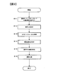
「オートコマ速連写1」を行う場合にCPU16が実行する処理の流れについて、図2に例示するフローチャートを参照して説明する。CPU16は、ユーザーによって「オートコマ速連写」へ切替え操作されると、図2による処理を起動させる。図2のステップS11において、CPU16は、低速で移動する(動きが小さい)被写体を連写撮影する「通常」モードと、より高速で移動する(動きが大きい)被写体を連写撮影する「スポーツ」モードとのいずれか一方を選択する操作を受け付ける。この選択操作は、例えばユーザーがメニュー操作によって行う。
ステップS12において、CPU16は、撮影レンズ11の焦点距離fに基づいて画角αを決定する。一般に、撮像素子12の撮像面のフレームサイズをS(mm)とすると、次式(1)が成立する。
S/2 =f×tan (α/2) ………… (1)
ただし、fは焦点距離(mm)である。CPU16は、レンズ駆動回路21から取得したズームレンズ位置を示す情報に基づいて焦点距離fを求め、撮像素子12のフレームサイズSおよび焦点距離fを上式(1)に代入して画角αを求める。ズームレンズ位置と焦点距離fとの関係を示すデータは、あらかじめ不揮発性メモリ17に格納されている。
S/2 =f×tan (α/2) ………… (1)
ただし、fは焦点距離(mm)である。CPU16は、レンズ駆動回路21から取得したズームレンズ位置を示す情報に基づいて焦点距離fを求め、撮像素子12のフレームサイズSおよび焦点距離fを上式(1)に代入して画角αを求める。ズームレンズ位置と焦点距離fとの関係を示すデータは、あらかじめ不揮発性メモリ17に格納されている。
図3は、35mm版システム(水平方向のフレームサイズSh=36mm×垂直方向のフレームサイズSv=24mm)に換算した焦点距離f(mm)と画角αとの関係を例示する図である。水平方向の画角αhと、垂直方向の画角αvとを、それぞれ単位(deg)で表したものである。画角αhとαvを決定したCPU16は、上述したライブビュー画像を液晶モニタ15に表示させながら、AF処理起動指示を待つ。CPU16はさらに、ライブビュー画像のデータ値に基づいて所定の露出演算を行いながら、適正露出が得られるように露出制御を行う。
図2のステップS13において、CPU16は、例えば半押しスイッチ20aがオンすると、AF処理を行ってステップS14へ進む。AF処理後のCPU16は、レンズ駆動回路21から取得したフォーカシングレンズ位置を示す情報に基づいて、デジタルカメラ1から焦点調節の対象となった被写体までの被写体距離D(m)を求める。フォーカシングレンズ位置と被写体距離D(m)との関係を示すデータは、あらかじめ不揮発性メモリ17に格納されている。
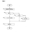
ステップS14において、CPU16は、被写体の移動速度aを設定する。移動速度aを設定する処理の詳細について、図4に例示するフローチャートを参照して説明する。図4のステップS51において、CPU16は、姿勢センサ26からの検出信号に基づいて横位置姿勢か縦位置姿勢かを判定し、ステップS52へ進む。
ステップS52において、CPU16は、直近のライブビュー画像から人物の「顔」を検出したか否かを判定する。CPU16は、公知の顔検出処理を行うことによってライブビュー画像から「顔」領域を検出した場合に、ステップS52を肯定判定してステップS53へ進む。CPU16は、ライブビュー画像から人物の「顔」領域を検出しなかった場合には、ステップS52を否定判定してステップS55へ進む。
ステップS53において、CPU16は、検出した「顔」が大人か、子供(小学生)か、幼児かを判定し、ステップS54へ進む。大人/子供/幼児の判別処理は公知であるので、判別処理の詳細説明は省略する。
ステップS52を否定判定して進むステップS55において、CPU16は、公知のペット検出処理を行うことによってライブビュー画像から「犬」または「猫」を検出した場合に、ステップS55を肯定判定してステップS54へ進む。CPU16は、ライブビュー画像から「犬」も「猫」も検出しなかった場合には、ステップS55を否定判定してステップS56へ進む。
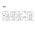
ステップS56において、CPU16はデフォルト設定を行ってステップS54へ進む。ステップS54において、CPU16は、「顔」に基づく判定結果、「犬」や「猫」の検出結果、およびデフォルト設定結果により、図5に例示するように移動速度aを設定して図4による処理を終了し、図2のステップS15へ進む。図5は、大人、子供(小学生)、幼児、および犬、猫の代表的な移動速度(m/秒)を表したものである。図5に例示したような移動速度aの値は、あらかじめ不揮発性メモリ17に格納されている。
図5において、「通常」モード、「スポーツ」モードは、ステップS11(図2)でユーザー操作に基づいて選択したモードにそれぞれ対応したものである。「通常」モードにおける移動速度(m/秒)は、大人、子供(小学生)、幼児がそれぞれ歩く速度に相当する。また、「スポーツ」モードにおける移動速度(m/秒)は、大人、子供(小学生)がそれぞれ走る速度に相当する。本実施形態では、幼児の歩く速度と走る速度とは区別しない。すなわち、「通常」モードと「スポーツ」モードとにかかわらずに同じ移動速度としている。デフォルト設定の場合の移動速度aの値は、例えば「通常」モードの場合に0.5(m/秒)、「スポーツ」モードの場合に2.0(m/秒)とする。デフォルト設定による移動速度aを「通常」モードと「スポーツ」モードとで区別して設けたので、顔検出やペット検出に基づいて被写体の移動速度を設定されなかった場合でも、ユーザー操作を反映させたデフォルト値を用いることができる。
「犬」および「猫」を検出した場合のCPU16は、「通常」モードであるか「スポーツ」モードであるかにかかわらず、人物より速い移動速度(10 m/秒)とする。なお、秒速だけではわかりにくいため、図5においては分速を併記した。
ステップS15において、CPU16は、次式(2)~(4)に基づいて連写コマ速度X(コマ/秒)を決定し、ステップS16へ進む。次式(2)の意味は、水平方向に移動する被写体像が撮影画面の一方の端から他方の端まで移動する間に略10コマ撮影するように連写コマ速度Xを演算することである。
X = 10 × a/L ………… (2)
ただし、符号aは上記移動速度であり、符号Lは撮影範囲(m)である。撮影範囲Lは横位置姿勢の場合と縦位置姿勢の場合とで異ならせる。図6は、横位置姿勢の場合の撮影画面を例示する図である。図7は、縦位置姿勢の場合の撮影画面を例示する図である。なお、横位置姿勢の場合の撮影範囲Lh(m)は次式(3)で、縦位置姿勢の場合の撮影範囲Lv(m)は次式(4)で、それぞれ求める。
ただし、符号aは上記移動速度であり、符号Lは撮影範囲(m)である。撮影範囲Lは横位置姿勢の場合と縦位置姿勢の場合とで異ならせる。図6は、横位置姿勢の場合の撮影画面を例示する図である。図7は、縦位置姿勢の場合の撮影画面を例示する図である。なお、横位置姿勢の場合の撮影範囲Lh(m)は次式(3)で、縦位置姿勢の場合の撮影範囲Lv(m)は次式(4)で、それぞれ求める。
Lh = Sh/f × D ………… (3)
ただし、符号Shは撮像素子12の撮像面の水平方向のフレームサイズ(mm)、符号fは焦点距離(mm)、符号Dは被写体距離(m)である。
ただし、符号Shは撮像素子12の撮像面の水平方向のフレームサイズ(mm)、符号fは焦点距離(mm)、符号Dは被写体距離(m)である。
Lv = Sv/f × D ………… (4)
ただし、符号Svは撮像素子12の撮像面の垂直方向のフレームサイズ(mm)、符号fは焦点距離(mm)、符号Dは被写体距離(m)である。
ただし、符号Svは撮像素子12の撮像面の垂直方向のフレームサイズ(mm)、符号fは焦点距離(mm)、符号Dは被写体距離(m)である。
具体例をあげて説明すると、「スポーツ」モードが選択されており、かつ「顔」を検出し、その人物は「大人」であると判定した場合であって、D=10(m)、f=20(mm)、Sh=20(mm)である場合には、図5より移動速度a=2.0(m/秒)であることから、X=10×2.0/10=2(コマ/秒)が算出される。
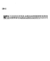
図8は、上述した演算結果と、CPU16が決定する連写コマ速度Xとの関係を例示する図である。本第1実施形態では、連写コマ速度制御を簡単にするため、連写コマ速度を段階的に変化させる。このためにCPU16は、演算結果としてXが10以上の場合はX=10(コマ/秒)とする。また、4≦X<10の場合はX=5(コマ/秒)、2≦X<4の場合はX=3(コマ/秒)、0.8≦X<2の場合はX=1(コマ/秒)、そしてX<0.8の場合はX=0.5(コマ/秒)とする。
ステップS16において、CPU16は撮影処理を行う。具体的には、撮影指示が行われている間、すなわち全押しスイッチ20bがオンしている間、図8に例示した連写コマ速度X(コマ/秒)で連写撮影する。なお、シャッター速度および絞り値は、例えば、直近のライブビュー画像のデータに基づく露出演算により決定した値を用いる。CPU16は、全押しスイッチ20bがオフすると新たな撮像を行わずに、取得済みの各コマの画像に基づいてそれぞれ生成した静止画像データをメモリカード50へ記録し、図2による処理を終了する。
以上説明した第1実施形態によれば、次の作用効果が得られる。
(1)デジタルカメラ1は、撮影指示に応じて複数コマの静止画像を所定の連写コマ速度Xで連続撮影する撮像素子12と、撮影範囲Lh(Lv)、被写体距離D、および「通常」モードか「スポーツ」モードかに基づいて、連写コマ速度Xを決定するCPU16と、CPU16で決定された連写コマ速度で連続撮影するように撮像素子12を制御するCPU16と、を備えるようにしたので、連写画像のコマ間で被写体像が適度な変化をするように連写撮影を行うことができる。
(1)デジタルカメラ1は、撮影指示に応じて複数コマの静止画像を所定の連写コマ速度Xで連続撮影する撮像素子12と、撮影範囲Lh(Lv)、被写体距離D、および「通常」モードか「スポーツ」モードかに基づいて、連写コマ速度Xを決定するCPU16と、CPU16で決定された連写コマ速度で連続撮影するように撮像素子12を制御するCPU16と、を備えるようにしたので、連写画像のコマ間で被写体像が適度な変化をするように連写撮影を行うことができる。
(2)上記デジタルカメラ1において、CPU16は、「通常」モードでは「スポーツ」モードに比べて連写コマ速度Xを遅くするので、コマ間で被写体像が適度に変化するように連写撮影することができる。
(3)上記(1)または(2)のデジタルカメラ1において、CPU16は、撮撮影範囲Lh(Lv)が広いほど連写コマ速度Xを遅くするので、コマ間で被写体像が適度に変化するように連写撮影することができる。
(4)上記(1)~(3)のデジタルカメラ1において、CPU16は、被写体距離Dが長いほど連写コマ速度Xを遅くするので、コマ間で被写体像が適度に変化するように連写撮影することができる。
(5)上記(1)~(4)のデジタルカメラ1において、被写体を撮像して画像データを出力する撮像素子12を有し、CPU16は、画像データに基づいて検出された人物の顔に基づいて、その人物が大人か、子供か、あるいは幼児かを判断し、その結果に応じて連写コマ速度を設定する。これにより、例えば子供の場合は大人の場合より連写コマ速度を遅くするなどして、コマ間で被写体像が適度に変化するように連写撮影することができる。
(6)上記(1)~(5)のデジタルカメラ1において、CPU16は、画像データに基づいて犬または猫が検出された場合のコマ速度に比べて、人物の顔が検出された場合のコマ速度よりも速く設定する。これにより、人物より速く移動する犬や猫の撮影にも、コマ間で被写体像の変化が大きすぎることなく、適度に変化するように連写撮影することができる。
(7)上記(1)~(6)のデジタルカメラ1において、縦位置姿勢か横位置姿勢かを判別する姿勢センサ26、CPU16をさらに備え、CPU16は、縦位置姿勢におけるコマ速度に比べて、横位置姿勢における連写コマ速度を遅く設定する。これにより、コマ間で適度に変化が得られるように連写撮影することができる。
(8)上記(1)~(7)のデジタルカメラ1において、CPU16は、「通常」モードか「スポーツ」モードかのそれぞれの設定の場合において、あらかじめ指示された移動速度値を用いるので、簡単な構成により、コマ間で適度に変化が得られるような連写撮影を実現できる。
(9)上記(1)~(8)のデジタルカメラ1において、CPU16は、撮影範囲Lh(Lv)、被写体距離D、および「通常」モードか「スポーツ」モードかに基づいて、段階的に異なる連写コマ速度を設定するので、多段階に細かく制御する場合に比べて連写撮影制御の構成を簡単にすることができる。
(変形例1)
上述した第1実施形態では、レリーズボタンの全押し操作が終了した場合に連写を終了する例を説明したが、これに加えて、被写体が移動して撮影画面から外れた場合にも自動的に連写撮影を終了するように構成してもよい。変形例1においてCPU16は、連写撮影で取得した最新コマの画像に対して公知の被写体追尾処理を行い、追尾対象となる主要被写体が最新コマの画像から検出されない場合に連写撮影を終了させる。
上述した第1実施形態では、レリーズボタンの全押し操作が終了した場合に連写を終了する例を説明したが、これに加えて、被写体が移動して撮影画面から外れた場合にも自動的に連写撮影を終了するように構成してもよい。変形例1においてCPU16は、連写撮影で取得した最新コマの画像に対して公知の被写体追尾処理を行い、追尾対象となる主要被写体が最新コマの画像から検出されない場合に連写撮影を終了させる。
(変形例2)
変形例1で、被写体が移動して撮影画面から外れたことにより連写撮影を終了した場合において、連写撮影終了後もレリーズボタンの全押し操作が継続されている間に主要被写体が再び撮影画面に含まれるようになった場合には、終了した連写撮影を再開してもよい。この場合のCPU16は、例えば、追尾していた「顔」と同じ「顔」が再び撮影画面に含まれるようになった場合に連写撮影を再開させる。
変形例1で、被写体が移動して撮影画面から外れたことにより連写撮影を終了した場合において、連写撮影終了後もレリーズボタンの全押し操作が継続されている間に主要被写体が再び撮影画面に含まれるようになった場合には、終了した連写撮影を再開してもよい。この場合のCPU16は、例えば、追尾していた「顔」と同じ「顔」が再び撮影画面に含まれるようになった場合に連写撮影を再開させる。
(変形例3)
上記の説明では、連写コマ速度Xを5段階に切替える例を説明したが、切替えステップや切替え段数を適宜設定しても構わない。例えば、上述した5段階よりさらに細かく10段階に切替えてもよいし、上述した5段階より粗い3段階に切替えるようにしてもよい。
上記の説明では、連写コマ速度Xを5段階に切替える例を説明したが、切替えステップや切替え段数を適宜設定しても構わない。例えば、上述した5段階よりさらに細かく10段階に切替えてもよいし、上述した5段階より粗い3段階に切替えるようにしてもよい。
(変形例4)
連写撮影中に、焦点距離fまたは被写体距離Dが変化した場合に、連写コマ速度Xの演算を新たに行うようしてもよい。これによってCPU16は、最新の焦点距離情報、被写体距離情報に基づいて連写コマ速度Xを決めることができる。なお、連写コマ速度Xの演算を新たに行う前に、不図示のランプを点滅させたり、スピーカ23から警告音を発生させるなどして、連写撮影中に焦点距離fまたは被写体距離Dが変化したことをユーザーに知らせるようにしてもよい。この場合、ユーザーは、例えば、連写撮影を新たにやり直すことができる。
連写撮影中に、焦点距離fまたは被写体距離Dが変化した場合に、連写コマ速度Xの演算を新たに行うようしてもよい。これによってCPU16は、最新の焦点距離情報、被写体距離情報に基づいて連写コマ速度Xを決めることができる。なお、連写コマ速度Xの演算を新たに行う前に、不図示のランプを点滅させたり、スピーカ23から警告音を発生させるなどして、連写撮影中に焦点距離fまたは被写体距離Dが変化したことをユーザーに知らせるようにしてもよい。この場合、ユーザーは、例えば、連写撮影を新たにやり直すことができる。
(変形例5)
上述した説明では、低速で移動する(動きが遅い)被写体を連写撮影するための「通常」モードと、より高速で移動する(動きが速い)被写体を連写撮影するための「スポーツ」モードとの切替えをユーザー操作によって行う(ステップS11)例を説明した。この代わりに、ライブビュー画像におけるフレーム画像間で検出される動きベクトルの大きさに基づいて、CPU16が「通常」モードと「スポーツ」モードとの切替えを自動的に行うようにしてもよい。
上述した説明では、低速で移動する(動きが遅い)被写体を連写撮影するための「通常」モードと、より高速で移動する(動きが速い)被写体を連写撮影するための「スポーツ」モードとの切替えをユーザー操作によって行う(ステップS11)例を説明した。この代わりに、ライブビュー画像におけるフレーム画像間で検出される動きベクトルの大きさに基づいて、CPU16が「通常」モードと「スポーツ」モードとの切替えを自動的に行うようにしてもよい。
(変形例6)
ライブビュー表示を行うデジタルカメラ1を例に説明したが、一眼レフタイプのカメラのように、通常時にライブビュー表示を行わないカメラにも本発明を適用できる。この場合には、例えば、測光用イメージセンサによって取得される画像に基づいて、人物の「顔」の検出や、検出した「顔」の人物が大人か、子供(小学生)か、あるいは幼児かを判定する。また、測光用イメージセンサによって取得される画像に基づいて、「犬」または「猫」を検出する。
ライブビュー表示を行うデジタルカメラ1を例に説明したが、一眼レフタイプのカメラのように、通常時にライブビュー表示を行わないカメラにも本発明を適用できる。この場合には、例えば、測光用イメージセンサによって取得される画像に基づいて、人物の「顔」の検出や、検出した「顔」の人物が大人か、子供(小学生)か、あるいは幼児かを判定する。また、測光用イメージセンサによって取得される画像に基づいて、「犬」または「猫」を検出する。
(変形例7)
上記実施形態では、「オートコマ速連写」を行う場合に、CPU16が決定した連写コマ速度X(コマ/秒)で撮像素子12に画像を取得させ、各コマの画像に基づいてそれぞれ生成した静止画像データをメモリカード50へ記録する例を説明した。この代わりに、撮像素子12で撮像した画像を一旦バッファメモリ18にバッファリングしておき、バッファメモリ18内の所定コマの画像を静止画像データとしてメモリカード50へ記録するようにしてもよい。
上記実施形態では、「オートコマ速連写」を行う場合に、CPU16が決定した連写コマ速度X(コマ/秒)で撮像素子12に画像を取得させ、各コマの画像に基づいてそれぞれ生成した静止画像データをメモリカード50へ記録する例を説明した。この代わりに、撮像素子12で撮像した画像を一旦バッファメモリ18にバッファリングしておき、バッファメモリ18内の所定コマの画像を静止画像データとしてメモリカード50へ記録するようにしてもよい。
具体的には、撮像素子12に所定コマ速度(例えば、10コマ/秒)で連続して画像を取得させ、取得された複数のフレーム画像を順次(時系列に)バッファメモリ18にバッファリングしておく。CPU16は、上述したように記録用の連写コマ速度X(コマ/秒)を決定し、バッファメモリ18内の画像のうち、決定したコマ速度Xに対応するフレーム画像を抽出して静止画像データをメモリカード50へ記録する。
例えば、決定した記録用の連写コマ速度X(コマ/秒)が10コマ/秒の場合はバッファメモリ18内に時系列に蓄積された全コマの画像をメモリカード50へ記録し、決定した記録用の連写コマ速度X(コマ/秒)が5コマ/秒の場合はバッファメモリ18内に時系列に蓄積された画像を1コマおきに読出してメモリカード50へ記録する。同様に、決定した記録用の連写コマ速度X(コマ/秒)が3コマ/秒の場合は、バッファメモリ18内に時系列に蓄積された画像を2コマおきに読出してメモリカード50へ記録し、決定した記録用の連写コマ速度X(コマ/秒)が1コマ/秒の場合は、バッファメモリ18内に時系列に蓄積された画像を9コマおきに読出してメモリカード50へ記録する。これにより、記録画像のコマ間で適切な変化を有するようにメモリカード50へ記録する連写撮影を行うことができる。
(変形例8)
デジタルカメラ1を例に説明したが、連写撮影機能を備えるものであれば、携帯電話機やタブレット端末などの電子機器にも本発明を適用して構わない。
デジタルカメラ1を例に説明したが、連写撮影機能を備えるものであれば、携帯電話機やタブレット端末などの電子機器にも本発明を適用して構わない。
(第2実施形態)
次に、本発明を実施するための第2実施形態について図面を参照して説明する。図1は、本発明の第2実施形態によるデジタルカメラ2の構成を例示するブロック図である。デジタルカメラ2の各構成要素とそれらの機能は、デジタルカメラ1と基本的に同様なので、個々の各構成要素とそれらの機能に関する説明は省略する。また、撮影モードについてもデジタルカメラ1と基本的に同様である。すなわち、「単写撮影モード」と、「連写撮影モード」と、「動画撮影モード」とが、モード切替スイッチによって択一的に切替え可能に構成されており、「連写撮影モード」においては、「オートコマ速連写」と、「マニュアルコマ速連写」とがユーザー操作によって切替え可能に構成されている。「オートコマ速連写」と「マニュアルコマ速連写」との切替えは、例えばユーザーがメニュー操作によって行うこともデジタルカメラ1と同様である。
次に、本発明を実施するための第2実施形態について図面を参照して説明する。図1は、本発明の第2実施形態によるデジタルカメラ2の構成を例示するブロック図である。デジタルカメラ2の各構成要素とそれらの機能は、デジタルカメラ1と基本的に同様なので、個々の各構成要素とそれらの機能に関する説明は省略する。また、撮影モードについてもデジタルカメラ1と基本的に同様である。すなわち、「単写撮影モード」と、「連写撮影モード」と、「動画撮影モード」とが、モード切替スイッチによって択一的に切替え可能に構成されており、「連写撮影モード」においては、「オートコマ速連写」と、「マニュアルコマ速連写」とがユーザー操作によって切替え可能に構成されている。「オートコマ速連写」と「マニュアルコマ速連写」との切替えは、例えばユーザーがメニュー操作によって行うこともデジタルカメラ1と同様である。
<オートコマ速連写2>
第2実施形態においても、「オートコマ速連写」に特徴を有するので、以降の説明は「オートコマ速連写2」を中心に行う。「オートコマ速連写2」を設ける目的は、連写撮影する際、被写体の動きの変化に対応してコマ速度を変化させることにある。すなわち、被写体の動きが速くなった場合には連写撮影コマ速度を増加させ、逆に、被写体の動きが遅くなった場合には連写撮影コマ数を減少させることが目的である。このためにCPU16は、被写体の動きが速くなった場合にはコマ間の時間を短くして高速で連写し、被写体の動きが遅くなった場合にはコマ間の時間を長くして低速で連写するように連写コマ速度を制御する。
第2実施形態においても、「オートコマ速連写」に特徴を有するので、以降の説明は「オートコマ速連写2」を中心に行う。「オートコマ速連写2」を設ける目的は、連写撮影する際、被写体の動きの変化に対応してコマ速度を変化させることにある。すなわち、被写体の動きが速くなった場合には連写撮影コマ速度を増加させ、逆に、被写体の動きが遅くなった場合には連写撮影コマ数を減少させることが目的である。このためにCPU16は、被写体の動きが速くなった場合にはコマ間の時間を短くして高速で連写し、被写体の動きが遅くなった場合にはコマ間の時間を長くして低速で連写するように連写コマ速度を制御する。
CPU16は、ユーザーによって「オートコマ速連写」へ切替えられている場合に「オートコマ速連写2」を実行する。「オートコマ速連写2」の処理の流れについて、図9に例示するフローチャートを参照して説明する。
CPU16は、ユーザーによりモード切替スイッチが「連写撮影モード」へ切替え操作されたことを受けて、撮影モードを「連写撮影モード」へ切替えて液晶モニタ15にライブビュー画像の表示を開始し、撮像素子12によって所定のフレームレート(例えば30fps)で取得されるモニタ用画像を表示する。
図9のステップS21において、CPU16は、「通常」モードと「スポーツ」モードとのいずれか一方を選択する操作を受け付ける。この選択操作は、例えばユーザーがメニュー操作によって行う。CPU16は、「スポーツ」モードが選択された場合、「通常」モードに比べてより速い連写コマ速度を設定するように制御する。
次に、CPU16は、図9のステップS22において、液晶モニタ15にライブビュー画像の表示を開始させる。ライブビュー画像は、撮影指示前に撮像素子12によって所定のフレームレート(例えば30fps)で取得されるモニタ用画像のことをいう。CPU16は、ライブビュー画像を液晶モニタ15に表示させながら、AF処理起動指示を待つ。CPU16はさらに、ライブビュー画像のデータ値に基づいて所定の露出演算を行いながら、適正露出が得られるように露出制御を行う。
ステップS23において、CPU16は、半押しスイッチ20aがオンしたか否かを判定する。CPU16は、上記半押し操作信号が入力された場合にステップS23を肯定判定してステップS24へ進む。CPU16は、上記半押し操作信号が入力されない場合には、ステップS23を否定判定し、当該判定処理を繰り返す。
ステップS24において、CPU16は、AF処理を行ってステップS25へ進む。AF処理後のCPU16は、ステップS25において、レンズ駆動回路21から取得したフォーカシングレンズ位置を示す情報に基づいて、デジタルカメラ2から焦点調節の対象となった主要被写体までの被写体距離Lを求める。フォーカシングレンズ位置と被写体距離L(m)との関係を示すデータは、あらかじめ不揮発性メモリ17に格納されている。
CPU16はさらに、ライブビュー画像を用いて、撮像素子12の撮像面12aにおいて被写体を抽出し、モニタ画面における被写体像の位置およびサイズを求める。被写体像の位置とサイズを求める処理の詳細について、図10に例示するフローチャートを参照して説明する。図10のステップS61において、CPU16は、姿勢センサ26からの検出信号に基づいて横位置姿勢か縦位置姿勢かを判定し、ステップS62へ進む。
ステップS62において、CPU16はライブビュー画像から被写体を抽出する処理を行ってステップS63へ進む。被写体抽出処理は、例えば焦点調節の対象となった領域を囲むエッジを検出したり、焦点調節の対象となった被写体領域と共通の輝度または色を有する領域を検出したりすることによって行う。図11は、被写体として鉄道車両が抽出された場合を例示する図である。
ステップS63において、CPU16は、抽出した被写体領域が、上述した撮像素子12の撮像面12aにおいて、撮像素子12の撮像面12aに占める被写体像の位置pとサイズrを求める。被写体像の位置については、例えば、撮像素子12の撮像面12aに占める被写体領域の水平方向および垂直方向の中心位置に該当する撮像素子の画素位置に基づいて求める。また、被写体像のサイズについては、例えば、撮像素子12の撮像面12aに占める被写体領域の水平方向および/または垂直方向の画素数に基づいて求める。CPU16は、被写体像の位置とサイズを求めたら、これらの情報を不揮発性メモリ17に格納し、図10による処理を終了して図9のステップS26に進む。
ステップS26において、CPU16は、全押しスイッチ20bがオンしたか否かを判定する。CPU16は、上記全押し操作信号が入力された場合にステップS26を肯定判定してステップS27へ進む。CPU16は、上記全押し操作信号が入力されない場合には、ステップS26を否定判定し、ステップS24へ戻って上述した処理を繰り返す。
ステップS27において、CPU16は、再度AF処理を行ってステップS28へ進む。AF処理後のCPU16は、ステップS28において、1コマの撮影をしてステップS29へ進む。ステップS29において、CPU16は、ステップS63の場合と同様に、被写体像の位置pおよびサイズrを求めるとともに、レンズ駆動回路21から取得したフォーカシングレンズ位置を示す情報に基づいて、デジタルカメラ2から焦点調節の対象となった主要被写体までの被写体距離Lを求め、ステップS30へ進む。
ステップS30において、CPU16は、直近のフレーム画像とその前のフレーム画像との間のフレーム間隔Δt1、被写体像位置の変化量Δp、被写体像サイズrの変化量Δrに基づいて、採用するコマ速度X(コマ/秒)あるいは次コマの撮影までの待ち時間すなわちコマ間隔Δt2(秒)を算出する。
例えば、1コマ目の撮影から連写2コマ目の撮影までのコマ間隔(すなわち待ち時間Δt2)を算出する場合に、全押し操作(S26)直前のライブビュー画像の撮像タイミングから、全押し操作(S26)後1コマ目の撮像タイミングまでの時間をΔt1とする。全押し操作(S26)直前のライブビュー画像における水平方向被写体像位置phおよび垂直方向位置pvと全押し操作(S26)後1コマ目の撮影画像における水平方向被写体像位置phおよび垂直方向位置pvとの差をそれぞれΔphおよびΔpvとする。また、全押し操作(S26)直前のライブビュー画像における被写体像サイズrと全押し操作(S26)後1コマ目の撮影画像における被写体像サイズrとの差を変化量Δrとする。
スポーツモードが設定された場合には、例えば、横位置姿勢または縦位置姿勢のフレームサイズの半分(1/2)を被写体像が移動する間に10コマを撮影するとして、コマ速度X(コマ/秒)とその場合のコマ間隔Δt2(秒)を求める。これにより、モニタ画像内における被写体像の変化が一定となるようにコマ速度あるいはコマ間隔を設定できる。
(被写体の水平方向の移動)
撮影画像内における被写体像の水平方向の移動に関して、時間Δt1における水平方向への移動Δphが速度変化なしに継続した場合に、横位置姿勢の場合のフレームサイズSh(mm)の1/2を移動するのに要する時間は、Sh×Δt1/2Δphで求められる。この間に10コマ撮影するためのコマ速度X(コマ/秒)と、その場合のコマ間隔Δt2(秒)は、
X=(20×Δph)/(Sh×Δt1) ………… (5)
この時のコマ間隔Δt2(秒)は、
Δt2=(Sh×Δt1)/(20×Δph) ………… (6)
撮影画像内における被写体像の水平方向の移動に関して、時間Δt1における水平方向への移動Δphが速度変化なしに継続した場合に、横位置姿勢の場合のフレームサイズSh(mm)の1/2を移動するのに要する時間は、Sh×Δt1/2Δphで求められる。この間に10コマ撮影するためのコマ速度X(コマ/秒)と、その場合のコマ間隔Δt2(秒)は、
X=(20×Δph)/(Sh×Δt1) ………… (5)
この時のコマ間隔Δt2(秒)は、
Δt2=(Sh×Δt1)/(20×Δph) ………… (6)
(被写体の垂直方向の移動)
同様に撮影画像内における被写体像の垂直方向の移動に関して、時間Δt1における垂直方向への移動Δpvが速度変化なしに継続した場合に、縦位置姿勢の場合のフレームサイズSv(mm)の1/2を移動するのに要する時間は、Sv×Δt1/2Δpvで求められる。この間に10コマ撮影するためのコマ速度X(コマ/秒)と、その場合のコマ間隔Δt2(秒)は、
X=(20×Δpv)/(Sv×Δt1) ………… (7)
この時のコマ間隔Δt2(秒)は、
Δt2=(Sv×Δt1)/(20×Δpv) ………… (8)
同様に撮影画像内における被写体像の垂直方向の移動に関して、時間Δt1における垂直方向への移動Δpvが速度変化なしに継続した場合に、縦位置姿勢の場合のフレームサイズSv(mm)の1/2を移動するのに要する時間は、Sv×Δt1/2Δpvで求められる。この間に10コマ撮影するためのコマ速度X(コマ/秒)と、その場合のコマ間隔Δt2(秒)は、
X=(20×Δpv)/(Sv×Δt1) ………… (7)
この時のコマ間隔Δt2(秒)は、
Δt2=(Sv×Δt1)/(20×Δpv) ………… (8)
CPU16は、コマ速度X(コマ/秒)として、式(5)および(7)のうち値の大きい方のコマ速度を採用する。あるいは、CPU16は、コマ間隔Δt2(秒)として、(6)および(8)のうち値の小さい方のコマ間隔を採用する。
通常モードが設定された場合には、例えば、横位置姿勢または縦位置姿勢のフレームサイズの半分(1/2)を被写体像が移動する間に5コマを撮影するとして、上記の手順と同様の手順により、コマ速度X(コマ/秒)とその場合のコマ間隔Δt2(秒)を求める。
(被写体の前後方向の移動)
次に、被写体が前後方向に移動する場合のコマ速度X(コマ/秒)とその場合のコマ間隔Δt2(秒)の設定に関して説明する。例えば、1コマ目の撮影から連写2コマ目の撮影までのコマ間隔(すなわち待ち時間Δt2)を算出する場合に、全押し操作(S26)直前のライブビュー画像の撮像タイミングから、全押し操作(S26)後1コマ目の撮像タイミングまでの時間をΔt1とする。全押し操作(S26)直前のライブビュー画像における被写体像サイズrと全押し操作(S26)後1コマ目の撮影画像における被写体像サイズrとの差を変化量Δrとする。カメラ方向に向かってくる(あるいは遠ざかる)被写体の撮像面12aにおける被写体像サイズrの変化量Δrが、撮像面12aのフレームサイズS相当になるまでの間に、スポーツモードでは略10コマ、通常モードでは略5コマ撮影するものとする。それぞれの場合で必要なコマ間隔Δt2は、次の(9)式および(10)式で表せる。
Δt2=Δt1×S/(10×Δr) ……(9)
Δt2=Δt1×S/(5×Δr) ……(10)
フレームサイズSとしては、横位置姿勢の場合には横位置姿勢の場合のフレームサイズはSh(mm)を用い、縦位置姿勢の場合には縦位置姿勢の場合のフレームサイズはSv(mm)を用いる。
このように、フレームサイズSに対して変化量Δrを所定の割合にするように次コマまでの撮影間隔を決める。これにより、変化量Δrが小さいほど撮影間隔を広げ(連写速度が遅くなる)、変化量Δrが大きいほど撮影間隔を狭くして上限値に近づける(連写速度が速くなる)。なお、フレームサイズSは、横位置姿勢の場合と縦位置姿勢の場合とで異ならせる。
図12は、横位置姿勢の場合の撮影画面を例示する図である。複数の主要被写体が検出されている場合は、焦点調節の対象となった主要被写体について被写体像サイズrを求める。図13は、縦位置姿勢の場合の撮影画面を例示する図である。この場合も、焦点調節の対象となった主要被写体について被写体像サイズrを求める。
図9のステップS31において、CPU16は、全押しスイッチ20bが継続してオンされているか否かを判定する。CPU16は、上記全押し操作信号が継続されている場合にステップS31を肯定判定してステップS32へ進む。CPU16は、上記全押し操作信号が入力されていない場合には、ステップS31を否定判定する。否定判定した場合は連写撮影を終了する。
ステップS31を肯定判定したCPU16は、ステップS32へ進んで連写撮影を行う。ステップS32において、CPU16は、撮像面12a上の被写体像の変化度合いが大きい側の所定値より大きいか否かを判定する。CPU16は、ステップS30で得た被写体像サイズrの変化量Δrが大きい側の所定値より大きい場合にステップS32を肯定判定してステップS33へ進む。CPU16は、ステップS30で得た変化量Δrが大きい側の所定値以下の場合には、ステップS32を否定判定してステップS34へ進む。
ステップS33へ進む場合は、主要被写体がデジタルカメラ2に接近して撮像面12a上の被写体像サイズrが急に大きくなる場合である。この場合のCPU16は、ステップS33において、連写撮影時のコマ間隔(時間t)を前コマ撮影時のコマ間隔よりさらに短くするように時間Δt2を制御するか、または、コマ速度X(コマ/秒)をより大きな値に変更するように制御して、ステップS36へ進む。
ステップS34において、CPU16は、撮像面12a上の被写体像の変化度合いが小さい側の所定値より小さいか否かを判定する。CPU16は、ステップS30で得た被写体像サイズrの変化量Δrが小さい側の所定値より小さい場合にステップS34を肯定判定してステップS35へ進む。CPU16は、ステップS30で得た変化量Δrが小さい側の所定値以上の場合には、ステップS34を否定判定してステップS36へ進む。
ステップS35へ進む場合は、主要被写体がデジタルカメラ2に接近して撮像面12a上の被写体像サイズrがあまり大きくならない場合である。この場合のCPU16は、ステップS35において、連写撮影時のコマ間隔(時間t)を前コマ撮影時のコマ間隔よりさらに長くするように時間Δt2を制御するか、または、コマ速度X(コマ/秒)をより小さな値に変更するように制御して、ステップS36へ進む。
ステップS36において、CPU16は、時間Δt2をカウントしてステップS27へ戻り、上述した処理を繰り返すか、または、新たに設定したコマ速度で撮影を繰り返す。これにより、コマ間隔t2をおいて次コマの連写撮影を行うか、または、コマ速度Xにおいて連写撮影を行う。CPU16は、ステップS30において連写3コマ目以降のコマ間隔(すなわち待ち時間Δt(n+1))を算出する場合には、前々コマの撮像タイミングから、前コマの撮像タミングまでの時間をフレーム間隔Δtnとし、前々コマの撮影画像における被写体像サイズrと前コマの撮影画像における被写体像サイズrとの差を変化量Δrとして、上記演算を行う。
このように、撮影指示が行われている間、すなわち全押しスイッチ20bがオンしている間、撮像面12a上の被写体像の変化度合いに基づいて演算したコマ速度で連写撮影する。CPU16は、全押しスイッチ20bがオフすると新たな撮像を行わずに、取得済みの各コマの画像に基づいてそれぞれ生成した静止画像データをメモリカード50へ記録する。
以上説明した第2実施形態によれば、次の作用効果が得られる。
(1)デジタルカメラ2は、撮影指示に応じて複数コマの静止画像を連続撮影する撮像素子12と、フレームサイズSh(Sv)に対する被写体像の移動量に基づいて、連続撮影のコマ速度を決定するCPU16と、CPU16で決定されたコマ速度で連続撮影するように撮像素子12を制御するCPU16と、を備えるようにしたので、被写体の移動速度に応じて連写画像のコマ間で適切な変化を有するように連写撮影を行うことができる。
(1)デジタルカメラ2は、撮影指示に応じて複数コマの静止画像を連続撮影する撮像素子12と、フレームサイズSh(Sv)に対する被写体像の移動量に基づいて、連続撮影のコマ速度を決定するCPU16と、CPU16で決定されたコマ速度で連続撮影するように撮像素子12を制御するCPU16と、を備えるようにしたので、被写体の移動速度に応じて連写画像のコマ間で適切な変化を有するように連写撮影を行うことができる。
(2)上記デジタルカメラ2は、撮影指示に応じて複数コマの静止画像を連続撮影する撮像素子12と、フレームサイズSh(Sv)に対する被写体像サイズの変化量に基づいて、連続撮影のコマ速度を決定するCPU16と、CPU16で決定されたコマ速度で連続撮影するように撮像素子12を制御するCPU16と、を備えるようにしたので、被写体の移動速度に応じて連写画像のコマ間で適切な変化を有するように連写撮影を行うことができる。
(3)上記デジタルカメラ2において、CPU16は、所定の上限コマ速度(例えば10コマ/秒)に対し、被写体像の移動速度が小さいほどコマ速度を遅くするので、コマ間で適度に変化が得られるように連写撮影することができる。
(4)上記デジタルカメラ2において、CPU16は、所定の上限コマ速度(例えば10コマ/秒)に対し、被写体像サイズの変化量が小さいほど、コマ速度を遅くするので、コマ間で適度に変化が得られるように連写撮影することができる。
(5)上記(1)および(3)のデジタルカメラ2において、CPU16は、フレームサイズSh(Sv)に対する被写体像の移動速度を所定の大きさとするようにコマごとに撮影間隔を決定するので、コマ間で適度に変化が得られるように連写撮影することができる。
(6)上記(2)および(4)のデジタルカメラ2において、CPU16は、フレームサイズSh(Sv)に対する被写体像サイズ変化を所定の割合とするようにコマごとに撮影間隔を決定するので、コマ間で適度に変化が得られるように連写撮影することができる。
(7)上記(5)のデジタルカメラ2において、CPU16は、被写体像の移動速度変化が所定値を超えた場合、コマ速度を前コマより速くするので、移動速度が急に増加した被写体に対し、コマ間で適度に変化が得られるように連写撮影することができる。
(8)上記(6)のデジタルカメラ2において、CPU16は、被写体像サイズの変化量が所定値を超えた場合にはコマ速度を前コマより速くするので、カメラに接近する速度が増加した被写体に対し、コマ間で適度に変化が得られるように連写撮影することができる。
(9)上記(1)~(5)のデジタルカメラ2において、縦位置姿勢か横位置姿勢かを判別する姿勢センサ26、CPU16をさらに備え、CPU16は、判別された姿勢において水平方向のフレームサイズSh(Sv)に対する被写体像の移動速度の変化量あるいは被写体像サイズrの変化量に基づいてコマ速度を決定するので、縦位置姿勢でも横位置姿勢でも、コマ間で適度に変化が得られるように連写撮影することができる。
(変形例9)
上述した第2実施形態では、撮像素子12の撮像面12aの大きさ(フレームサイズ)と、撮像素子12の撮像面12aに占める被写体像の被写体像サイズの変化量の関係から、コマ間隔Δt2を算出した。しかし、コマ間隔Δt2を算出する際に、撮像光学系11の焦点距離fと画角αの関係に基づいて求めた画角αと、全押し操作(S26)直前に得た被写体距離Lと全押し操作(S26)後1コマ目の撮影時に得た被写体距離Lとの差をΔLを用いてコマ間隔Δt2を算出してもよい。この場合、コマ間隔Δt2の算出は次のような手順で行われる。
上述した第2実施形態では、撮像素子12の撮像面12aの大きさ(フレームサイズ)と、撮像素子12の撮像面12aに占める被写体像の被写体像サイズの変化量の関係から、コマ間隔Δt2を算出した。しかし、コマ間隔Δt2を算出する際に、撮像光学系11の焦点距離fと画角αの関係に基づいて求めた画角αと、全押し操作(S26)直前に得た被写体距離Lと全押し操作(S26)後1コマ目の撮影時に得た被写体距離Lとの差をΔLを用いてコマ間隔Δt2を算出してもよい。この場合、コマ間隔Δt2の算出は次のような手順で行われる。
CPU16は、ステップS21終了後、撮像光学系11の焦点距離fに基づいて画角αを決定する。画角αを決定する手順は、第1実施形態に記載した手順と同様である。焦点距離f(mm)と画角αとの関係については図3に例示した通りである。
CPU16は、スポーツモードの場合に次式(9)とおき、通常モードの場合には次式(10)とおいて、次式(11)により時間Δt2を算出する。
10=S/Δr
=2×f×tan (α/2)/Δr ……(11)
5=S/Δr
=2×f×tan (α/2)/Δr ……(12)
ただし、符号fは撮像光学系11の焦点距離である。符号αは式(1)の画角に相当する。
Δt2=Δr×Δt1/(2×tan (α/2)×ΔL) ……(13)
10=S/Δr
=2×f×tan (α/2)/Δr ……(11)
5=S/Δr
=2×f×tan (α/2)/Δr ……(12)
ただし、符号fは撮像光学系11の焦点距離である。符号αは式(1)の画角に相当する。
Δt2=Δr×Δt1/(2×tan (α/2)×ΔL) ……(13)
上式(11)の意味は、カメラ方向に向かってくる(あるいは遠ざかる)被写体の撮像面12aにおける被写体像サイズrの変化量Δrが、撮像面12aのフレームサイズS(水平方向)相当になるまでの間に略10コマ撮影するように連写コマ速度を演算することである。また、上式(10)の意味は、カメラ方向に向かってくる(あるいは遠ざかる)被写体の撮像面12aにおける被写体像サイズrの変化量Δrが、撮像面12aのフレームサイズS(水平方向)相当になるまでの間に略5コマ撮影するように連写コマ速度を演算することである。
(変形例10)
上述した第2実施形態では、レリーズボタンの全押し操作が終了した場合に連写を終了する例を説明したが、これに加えて、主要被写体が接近して撮影画面(画角)外へはみ出す場合にも自動的に連写撮影を終了するように構成してもよい。変形例1のCPU16は、連写撮影で取得した最新コマの画像について、撮像面12a上の被写体像サイズrがフレームサイズSvまたはShに収まらない場合に連写撮影を終了させる。
上述した第2実施形態では、レリーズボタンの全押し操作が終了した場合に連写を終了する例を説明したが、これに加えて、主要被写体が接近して撮影画面(画角)外へはみ出す場合にも自動的に連写撮影を終了するように構成してもよい。変形例1のCPU16は、連写撮影で取得した最新コマの画像について、撮像面12a上の被写体像サイズrがフレームサイズSvまたはShに収まらない場合に連写撮影を終了させる。
(変形例11)
上式(3)の値は、適宜設定して構わない。例えば、スポーツモードの場合に8コマ撮影し、通常モードの場合に3コマ撮影するように連写コマ速度を演算させてもよい。
上式(3)の値は、適宜設定して構わない。例えば、スポーツモードの場合に8コマ撮影し、通常モードの場合に3コマ撮影するように連写コマ速度を演算させてもよい。
(変形例12)
連写撮影中に、焦点距離fが変化した場合には、ステップS23まで戻って上述した処理を繰り返すようしてもよい。これによってCPU16は、最新の焦点距離情報、被写体距離情報に基づいて連写コマ速度を決めることができる。なお、連写コマ速度の演算を新たに行う前に、不図示のランプを点滅させたり、スピーカ23から警告音を発生させるなどして、連写撮影中に焦点距離fが変化したことをユーザーに知らせるようにしてもよい。この場合のユーザーは、例えば、連写撮影を新たにやり直すことができる。
連写撮影中に、焦点距離fが変化した場合には、ステップS23まで戻って上述した処理を繰り返すようしてもよい。これによってCPU16は、最新の焦点距離情報、被写体距離情報に基づいて連写コマ速度を決めることができる。なお、連写コマ速度の演算を新たに行う前に、不図示のランプを点滅させたり、スピーカ23から警告音を発生させるなどして、連写撮影中に焦点距離fが変化したことをユーザーに知らせるようにしてもよい。この場合のユーザーは、例えば、連写撮影を新たにやり直すことができる。
(変形例13)
上述した説明では、低速で移動する被写体を連写撮影する「通常」モードと、「通常」モードの場合より高速で移動する被写体を連写撮影する「スポーツ」モードとの切替えをユーザー操作によって行う(ステップS21)例を説明した。このような設定に代えて、撮像面12a上の被写体像の変化度合いに基づいてCPU16が自動的に切替えるようにしてもよい。被写体像の変化度合いは、被写体像の移動速度やサイズの変化量から判断すればよい。その際、被写体の前後方向への移動に関しては、被写体距離の変化量に基づいて判断してもよい。
上述した説明では、低速で移動する被写体を連写撮影する「通常」モードと、「通常」モードの場合より高速で移動する被写体を連写撮影する「スポーツ」モードとの切替えをユーザー操作によって行う(ステップS21)例を説明した。このような設定に代えて、撮像面12a上の被写体像の変化度合いに基づいてCPU16が自動的に切替えるようにしてもよい。被写体像の変化度合いは、被写体像の移動速度やサイズの変化量から判断すればよい。その際、被写体の前後方向への移動に関しては、被写体距離の変化量に基づいて判断してもよい。
(変形例14)
ライブビュー表示を行うデジタルカメラ2を例に説明したが、一眼レフタイプのカメラのように、通常時にライブビュー表示を行わないカメラにも本発明を適用できる。この場合には、例えば、測光用イメージセンサによって取得される画像に基づいて被写体の抽出を行なう。
ライブビュー表示を行うデジタルカメラ2を例に説明したが、一眼レフタイプのカメラのように、通常時にライブビュー表示を行わないカメラにも本発明を適用できる。この場合には、例えば、測光用イメージセンサによって取得される画像に基づいて被写体の抽出を行なう。
(変形例15)
上記第2実施形態では、「オートコマ速連写」を行う場合に、CPU16が決定した連写コマ速度(コマ間隔)で撮像素子12に画像を取得させ、各コマの画像に基づいてそれぞれ生成した静止画像データをメモリカード50へ記録する例を説明した。この代わりに、撮像素子12で撮像した画像を一旦バッファメモリ18にバッファリングしておき、バッファメモリ18内の所定コマの画像を静止画像データとしてメモリカード50へ記録するようにしてもよい。
上記第2実施形態では、「オートコマ速連写」を行う場合に、CPU16が決定した連写コマ速度(コマ間隔)で撮像素子12に画像を取得させ、各コマの画像に基づいてそれぞれ生成した静止画像データをメモリカード50へ記録する例を説明した。この代わりに、撮像素子12で撮像した画像を一旦バッファメモリ18にバッファリングしておき、バッファメモリ18内の所定コマの画像を静止画像データとしてメモリカード50へ記録するようにしてもよい。
具体的には、撮像素子12に所定コマ速度(例えば、10コマ/秒)で連続して画像を取得させ、取得された複数のフレーム画像を順次(時系列に)バッファメモリ18にバッファリングしておく。CPU16は、上述したように記録用の連写コマ間隔を決定し、バッファメモリ18内の画像のうち、決定したコマ間隔に対応するフレーム画像を抽出して静止画像データをメモリカード50へ記録する。
例えば、決定した記録用の連写コマ間隔が10コマ/秒相当の場合はバッファメモリ18内に時系列に蓄積された全コマの画像をメモリカード50へ記録し、決定した記録用の連写コマ間隔が5コマ/秒相当の場合はバッファメモリ18内に時系列に蓄積された画像を1コマおきに読出してメモリカード50へ記録する。同様に、決定した記録用の連写コマ間隔が3コマ/秒相当の場合は、バッファメモリ18内に時系列に蓄積された画像を2コマおきに読出してメモリカード50へ記録する。このように、記録画像のコマ間で適切な変化を有するようにメモリカード50へ記録する連写撮影を行うことができる。
(変形例16)
上記第2実施形態では、全押し操作(S26)直前の画像と全押し操作(S26)後1コマ目の撮像画像から、被写体像の移動量または被写体像のサイズ変化量を求め、それに基づいて、連写撮影時のコマ速度やコマ間隔を求めた。しかし、コマ速度やコマ間隔は、これら2画像に基づいて求めることに限定されない。例えば、全押し操作(S26)前の2フレームのライブビュー画像により被写体像の移動量または被写体像のサイズ変化量を求め、それに基づいて、連写撮影時のコマ速度やコマ間隔を求めてもよい。2フレームのライブビュー画像は適当な時間間隔を隔てていてもよいし、連続していてもよい。
上記第2実施形態では、全押し操作(S26)直前の画像と全押し操作(S26)後1コマ目の撮像画像から、被写体像の移動量または被写体像のサイズ変化量を求め、それに基づいて、連写撮影時のコマ速度やコマ間隔を求めた。しかし、コマ速度やコマ間隔は、これら2画像に基づいて求めることに限定されない。例えば、全押し操作(S26)前の2フレームのライブビュー画像により被写体像の移動量または被写体像のサイズ変化量を求め、それに基づいて、連写撮影時のコマ速度やコマ間隔を求めてもよい。2フレームのライブビュー画像は適当な時間間隔を隔てていてもよいし、連続していてもよい。
(変形例17)
デジタルカメラ2を例に説明したが、連写撮影機能を備えるものであれば、携帯電話機やタブレット端末などの電子機器にも本発明を適用して構わない。
デジタルカメラ2を例に説明したが、連写撮影機能を備えるものであれば、携帯電話機やタブレット端末などの電子機器にも本発明を適用して構わない。
以上の説明はあくまで一例であり、上記の実施形態の構成に何ら限定されるものではない。
次の優先権基礎出願の開示内容は引用文としてここに組み込まれる。
日本国特許出願2011年第267205号(2011年12月6日出願)
日本国特許出願2012年第141663号(2012年6月25日出願)
日本国特許出願2011年第267205号(2011年12月6日出願)
日本国特許出願2012年第141663号(2012年6月25日出願)
Claims (19)
- 被写体像を撮像する撮像素子と、
被写体像を前記撮像素子の撮像面に結像させる撮像光学系と、
前記撮像素子により、所定のフレームレートでモニタ画像を取得するライブビュー画像取得部と、
前記モニタ画像から被写体を抽出する被写体抽出部と、
前記被写体を連続撮影する際のコマ速度を演算するコマ速度演算部と、
撮影指示に応じて複数の静止画像を連続撮影する撮影部と、
前記コマ速度演算部で演算された前記コマ速度で連続撮影するように前記撮影部を制御する制御部と、
前記撮影部により撮影された静止画像を記録媒体に記録する画像記録部と、
を備え、
前記コマ速度演算部は、前記被写体抽出部により抽出した被写体に基づいて、前記被写体を連続撮影する際のコマ速度を演算する撮像装置。 - 請求項1に記載の撮像装置において、
前記被写体抽出部が抽出した前記被写体の種類を特定する被写体特定部と、
前記被写体の種類に対応する移動速度データを記憶する記憶部と、を更に備え、
前記コマ速度演算部は、前記被写体特定部が特定した前記被写体の種類に対応する前記移動速度データを前記記憶部から読み出し、該移動速度データに基づいて連続撮影する際のコマ速度を演算する撮像装置。 - 請求項2に記載の撮像装置において、
前記被写体特定部は、人物または動物のいずれであるかを特定する撮像装置。 - 請求項3に記載の撮像装置において、
前記被写体特定部は、人物である場合には大人および子供および幼児のうちのいずれであるかを特定し、動物である場合には犬または猫であるかどうかを特定する撮像装置。 - 請求項4に記載の撮像装置において、
前記記憶部は、前記大人、子供、幼児、犬または猫のそれぞれに対応した移動速度データを、それぞれ1または複数ずつ記憶している撮像装置。 - 請求項1に記載の撮像装置において、
前記被写体抽出部が抽出した前記被写体の前記モニタ画像間における変化に基づいて、前記モニタ画像における前記被写体像の移動情報を取得する移動情報取得部を更に備え、
前記コマ速度演算部は、前記移動情報取得部が取得した前記モニタ画像における前記被写体像の移動情報に基づいて連続撮影する際のコマ速度を演算する撮像装置。 - 請求項6に記載の撮像装置において、
前記被写体抽出部が抽出した前記被写体の前記モニタ画像間における前記被写体像の変化は、前記モニタ画像間における前記被写体像の横方向または縦方向への移動量である撮像装置。 - 請求項6に記載の撮像装置において、
前記被写体抽出部が抽出した前記被写体の前記モニタ画像間における前記被写体像の変化は、前記モニタ画像間における前記被写体像の大きさの変化である撮像装置。 - 請求項7または8のいずれか一項に記載の撮像装置において、
前記コマ速度演算部は、前記被写体像の大きさの割合が変化が上限値を超えた場合には前記撮影間隔を短くし、前記被写体像の大きさの変化の割合が下限値を超えた場合には前記撮影間隔を長くする撮像装置。 - 請求項7または8のいずれか一項に記載の撮像装置において、
前記コマ速度演算部は、前記被写体像の変化が所定の値を維持するように、1コマ撮影するごとに、次のコマを撮影するまでの撮影間隔を決定する撮像装置。 - 請求項2に記載の撮像装置において、
前記コマ速度演算部は、前記移動速度データの値が小さいほどコマ速度を遅くする撮像装置。 - 請求項7または8のいずれか一項に記載の撮像装置において、
前記被写体像の変化が小さいほどコマ速度を遅くする撮像装置。 - 請求項2~12に記載の撮像装置において、
前記コマ速度演算部は、前記移動速度データまたは移動情報に加えて、更に、撮影画角情報および被写体距離情報に基づいて前記連続撮影する際のコマ速度を演算する撮像装置。 - 請求項13に記載の撮像装置において、
前記コマ速度演算部は、撮影画角が広いほど前記コマ速度を遅くする撮像装置。 - 請求項13に記載の撮像装置において、
前記コマ速度演算部は、被写体距離が長いほど前記コマ速度を遅くする撮像装置。 - 請求項13に記載の撮像装置において、
前記コマ速度演算部は、前記連続撮影中に前記撮像画角が変化した場合に、前記コマ速度を演算し直す撮像装置。 - 請求項13に記載の撮像装置において、
前記コマ速度演算部は、前記連続撮影中に前記被写体距離が変化した場合に再度前記コマ速度を演算する撮像装置。 - 請求項1~17のいずれか一項に記載の撮像装置において、
前記撮像装置が縦位置姿勢か横位置姿勢かを判別する姿勢判別部をさらに備え、
前記コマ速度演算部は、前記横位置姿勢の場合における前記コマ速度を前記撮像装置が前記縦位置姿勢の場合よりも遅くする撮像装置。 - 請求項1~18のいずれか一項に記載の撮像装置において、
前記撮像素子が撮像した前記被写体像の前記静止画像を、前記コマ速度で順次記憶する記憶部材と、
前記記憶部材に順次記憶された静止画像のうち、前記コマ速度演算部で演算されたコマ速度に対応する複数コマの静止画像を、前記記録媒体に記録するように前記画像記録部を制御する制御部とを備える撮像装置。
Applications Claiming Priority (4)
| Application Number | Priority Date | Filing Date | Title |
|---|---|---|---|
| JP2011-267205 | 2011-12-06 | ||
| JP2011267205A JP2015035638A (ja) | 2011-12-06 | 2011-12-06 | 撮像装置 |
| JP2012-141663 | 2012-06-25 | ||
| JP2012141663A JP2015035640A (ja) | 2012-06-25 | 2012-06-25 | 撮像装置 |
Publications (1)
| Publication Number | Publication Date |
|---|---|
| WO2013084780A1 true WO2013084780A1 (ja) | 2013-06-13 |
Family
ID=48574150
Family Applications (1)
| Application Number | Title | Priority Date | Filing Date |
|---|---|---|---|
| PCT/JP2012/080881 Ceased WO2013084780A1 (ja) | 2011-12-06 | 2012-11-29 | 撮像装置 |
Country Status (1)
| Country | Link |
|---|---|
| WO (1) | WO2013084780A1 (ja) |
Cited By (2)
| Publication number | Priority date | Publication date | Assignee | Title |
|---|---|---|---|---|
| JP2015156201A (ja) * | 2014-01-17 | 2015-08-27 | カシオ計算機株式会社 | 電子装置並びにシステム、方法、プログラム |
| CN113194246A (zh) * | 2021-04-02 | 2021-07-30 | 烟台艾睿光电科技有限公司 | 一种移动设备的图像显示方法及装置 |
Citations (5)
| Publication number | Priority date | Publication date | Assignee | Title |
|---|---|---|---|---|
| JPH05137053A (ja) * | 1991-11-15 | 1993-06-01 | Kyocera Corp | 撮影速度制御方式 |
| JP2009075398A (ja) * | 2007-09-21 | 2009-04-09 | Olympus Imaging Corp | 撮像装置 |
| JP2009111949A (ja) * | 2007-11-01 | 2009-05-21 | Olympus Corp | カメラ |
| JP2010171491A (ja) * | 2009-01-20 | 2010-08-05 | Casio Computer Co Ltd | 撮影装置、撮影方法及びプログラム |
| JP2010199884A (ja) * | 2009-02-24 | 2010-09-09 | Nikon Corp | 撮像装置 |
-
2012
- 2012-11-29 WO PCT/JP2012/080881 patent/WO2013084780A1/ja not_active Ceased
Patent Citations (5)
| Publication number | Priority date | Publication date | Assignee | Title |
|---|---|---|---|---|
| JPH05137053A (ja) * | 1991-11-15 | 1993-06-01 | Kyocera Corp | 撮影速度制御方式 |
| JP2009075398A (ja) * | 2007-09-21 | 2009-04-09 | Olympus Imaging Corp | 撮像装置 |
| JP2009111949A (ja) * | 2007-11-01 | 2009-05-21 | Olympus Corp | カメラ |
| JP2010171491A (ja) * | 2009-01-20 | 2010-08-05 | Casio Computer Co Ltd | 撮影装置、撮影方法及びプログラム |
| JP2010199884A (ja) * | 2009-02-24 | 2010-09-09 | Nikon Corp | 撮像装置 |
Cited By (2)
| Publication number | Priority date | Publication date | Assignee | Title |
|---|---|---|---|---|
| JP2015156201A (ja) * | 2014-01-17 | 2015-08-27 | カシオ計算機株式会社 | 電子装置並びにシステム、方法、プログラム |
| CN113194246A (zh) * | 2021-04-02 | 2021-07-30 | 烟台艾睿光电科技有限公司 | 一种移动设备的图像显示方法及装置 |
Similar Documents
| Publication | Publication Date | Title |
|---|---|---|
| CN101931752B (zh) | 摄像装置、以及对焦方法 | |
| JP5394296B2 (ja) | 撮像装置及び画像処理方法 | |
| JP4976160B2 (ja) | 撮像装置 | |
| CN101317445B (zh) | 摄像装置和摄像装置本体 | |
| CN101867725B (zh) | 摄像装置和拍摄对象跟踪方法 | |
| JP5447619B2 (ja) | 撮像装置 | |
| US20080181460A1 (en) | Imaging apparatus and imaging method | |
| US10542216B2 (en) | Apparatus and method for storing moving image portions | |
| JP5931619B2 (ja) | 撮像装置 | |
| JP2013150210A (ja) | 撮影装置 | |
| US20160301858A1 (en) | Control apparatus, storage medium for storing control program, control method, and optical apparatus | |
| JP2010199694A (ja) | 撮像装置、画角調節方法、及び、プログラム | |
| KR101630304B1 (ko) | 디지털 촬영 장치, 그 제어 방법, 및 컴퓨터 판독가능 매체 | |
| JP2014053863A (ja) | 撮影機器 | |
| JP5448868B2 (ja) | 撮像装置および撮像装置の制御方法 | |
| JP2012173709A (ja) | 撮像装置 | |
| JP7563962B2 (ja) | 焦点検出装置および焦点検出方法 | |
| JP2015035638A (ja) | 撮像装置 | |
| JP5846928B2 (ja) | 撮像装置 | |
| JP2014048393A (ja) | 撮像装置 | |
| JP2014158221A (ja) | 撮像装置 | |
| JP2015035640A (ja) | 撮像装置 | |
| WO2013065642A1 (ja) | 画像処理装置 | |
| JP2014086870A (ja) | 撮像装置およびプログラム | |
| JP2012138813A (ja) | 撮影機器 |
Legal Events
| Date | Code | Title | Description |
|---|---|---|---|
| 121 | Ep: the epo has been informed by wipo that ep was designated in this application |
Ref document number: 12855360 Country of ref document: EP Kind code of ref document: A1 |
|
| NENP | Non-entry into the national phase |
Ref country code: DE |
|
| 122 | Ep: pct application non-entry in european phase |
Ref document number: 12855360 Country of ref document: EP Kind code of ref document: A1 |
|
| NENP | Non-entry into the national phase |
Ref country code: JP |