WO2013084743A1 - ダイヤフラム弁およびダイヤフラム弁用シートホルダユニット - Google Patents
ダイヤフラム弁およびダイヤフラム弁用シートホルダユニット Download PDFInfo
- Publication number
- WO2013084743A1 WO2013084743A1 PCT/JP2012/080535 JP2012080535W WO2013084743A1 WO 2013084743 A1 WO2013084743 A1 WO 2013084743A1 JP 2012080535 W JP2012080535 W JP 2012080535W WO 2013084743 A1 WO2013084743 A1 WO 2013084743A1
- Authority
- WO
- WIPO (PCT)
- Prior art keywords
- diaphragm
- seat
- retainer
- seat holder
- holder
- Prior art date
- Legal status (The legal status is an assumption and is not a legal conclusion. Google has not performed a legal analysis and makes no representation as to the accuracy of the status listed.)
- Ceased
Links
Images

Classifications
-
- F—MECHANICAL ENGINEERING; LIGHTING; HEATING; WEAPONS; BLASTING
- F16—ENGINEERING ELEMENTS AND UNITS; GENERAL MEASURES FOR PRODUCING AND MAINTAINING EFFECTIVE FUNCTIONING OF MACHINES OR INSTALLATIONS; THERMAL INSULATION IN GENERAL
- F16K—VALVES; TAPS; COCKS; ACTUATING-FLOATS; DEVICES FOR VENTING OR AERATING
- F16K7/00—Diaphragm valves or cut-off apparatus, e.g. with a member deformed, but not moved bodily, to close the passage ; Pinch valves
- F16K7/12—Diaphragm valves or cut-off apparatus, e.g. with a member deformed, but not moved bodily, to close the passage ; Pinch valves with flat, dished, or bowl-shaped diaphragm
- F16K7/14—Diaphragm valves or cut-off apparatus, e.g. with a member deformed, but not moved bodily, to close the passage ; Pinch valves with flat, dished, or bowl-shaped diaphragm arranged to be deformed against a flat seat
-
- F—MECHANICAL ENGINEERING; LIGHTING; HEATING; WEAPONS; BLASTING
- F16—ENGINEERING ELEMENTS AND UNITS; GENERAL MEASURES FOR PRODUCING AND MAINTAINING EFFECTIVE FUNCTIONING OF MACHINES OR INSTALLATIONS; THERMAL INSULATION IN GENERAL
- F16K—VALVES; TAPS; COCKS; ACTUATING-FLOATS; DEVICES FOR VENTING OR AERATING
- F16K7/00—Diaphragm valves or cut-off apparatus, e.g. with a member deformed, but not moved bodily, to close the passage ; Pinch valves
- F16K7/12—Diaphragm valves or cut-off apparatus, e.g. with a member deformed, but not moved bodily, to close the passage ; Pinch valves with flat, dished, or bowl-shaped diaphragm
- F16K7/14—Diaphragm valves or cut-off apparatus, e.g. with a member deformed, but not moved bodily, to close the passage ; Pinch valves with flat, dished, or bowl-shaped diaphragm arranged to be deformed against a flat seat
- F16K7/16—Diaphragm valves or cut-off apparatus, e.g. with a member deformed, but not moved bodily, to close the passage ; Pinch valves with flat, dished, or bowl-shaped diaphragm arranged to be deformed against a flat seat the diaphragm being mechanically actuated, e.g. by screw-spindle or cam
-
- F—MECHANICAL ENGINEERING; LIGHTING; HEATING; WEAPONS; BLASTING
- F16—ENGINEERING ELEMENTS AND UNITS; GENERAL MEASURES FOR PRODUCING AND MAINTAINING EFFECTIVE FUNCTIONING OF MACHINES OR INSTALLATIONS; THERMAL INSULATION IN GENERAL
- F16K—VALVES; TAPS; COCKS; ACTUATING-FLOATS; DEVICES FOR VENTING OR AERATING
- F16K7/00—Diaphragm valves or cut-off apparatus, e.g. with a member deformed, but not moved bodily, to close the passage ; Pinch valves
- F16K7/12—Diaphragm valves or cut-off apparatus, e.g. with a member deformed, but not moved bodily, to close the passage ; Pinch valves with flat, dished, or bowl-shaped diaphragm
- F16K7/14—Diaphragm valves or cut-off apparatus, e.g. with a member deformed, but not moved bodily, to close the passage ; Pinch valves with flat, dished, or bowl-shaped diaphragm arranged to be deformed against a flat seat
- F16K7/17—Diaphragm valves or cut-off apparatus, e.g. with a member deformed, but not moved bodily, to close the passage ; Pinch valves with flat, dished, or bowl-shaped diaphragm arranged to be deformed against a flat seat the diaphragm being actuated by fluid pressure
Definitions
- This invention relates to a diaphragm valve and a seat holder unit for a diaphragm valve, and more particularly to a diaphragm valve in which a seat is detachable and held by the seat holder, and a seat holder unit used in such a diaphragm valve.
- a body provided with a fluid passage, a seat detachably disposed on the periphery of the fluid passage formed in the body, a seat holder detachably disposed on the body and holding the seat, and a seat Up and down movement to move up and down a diaphragm that opens and closes the fluid passage by being pressed and separated, a diaphragm holding member that holds the outer peripheral edge of the diaphragm between the sheet holder, and a diaphragm presser that presses the center of the diaphragm
- a device including a means is known (for example, Patent Document 1).
- the seat is made detachable and held by the seat holder, and when the seat is damaged, only this can be replaced.
- the conventional device has a problem in that it is difficult to replace the sheet when the sheet holder is plastically deformed and cannot be removed.
- An object of the present invention is to provide a diaphragm valve and a seat holder unit for a diaphragm valve that can facilitate sheet replacement.
- a diaphragm valve includes a body provided with a fluid passage, a seat disposed at the periphery of the fluid passage formed in the body, a seat holder that is detachably disposed on the body and holds the seat, and a seat Up and down movement to move up and down a diaphragm that opens and closes the fluid passage by being pressed and separated, a diaphragm holding member that holds the outer peripheral edge of the diaphragm between the sheet holder, and a diaphragm presser that presses the center of the diaphragm
- the diaphragm valve further includes a retainer for holding the seat holder, and the retainer is detachably attached to the diaphragm holding member while holding the seat holder. is there.
- the diaphragm valve may be a manual valve such as an open / close handle as the vertical movement means, or an automatic valve in which the vertical movement means is an appropriate actuator.
- the actuator is a fluid (air) It may be by pressure or by electromagnetic force.
- Diaphragm holding member refers to a member that is fixed to the body and clamps the outer peripheral edge of the diaphragm with the seat holder.
- an annularly formed diaphragm holding ring and a member for fixing the diaphragm holding ring to the body may also serve as the diaphragm holding member.
- the retainer is, for example, substantially cylindrical and has an inward flange portion that receives the outer peripheral edge portion of the seat holder. Any flange portion is acceptable as long as the seat holder does not fall off the retainer. Instead of the inward flange portion, a configuration having a protrusion shape for holding the sheet holder may be used. .
- the sheet is preferably replaced when used for a long period of time.
- the retainer is removed to remove the sheet holder held by the retainer and the sheet held by the retainer.
- the sheet can be removed, and the sheet can be easily replaced (only the sheet can be replaced, or both the sheet holder and the sheet can be replaced). Since the seat holder clamps the outer peripheral edge of the diaphragm, it may be plastically deformed. On the other hand, since the retainer only needs to be detachably attached to the diaphragm holding member, it may be plastically deformed. The ease of sheet replacement is maintained over a long period of time.
- the sheet is made of, for example, a synthetic resin, but may be made of metal.
- the sheet holder and the retainer are preferably made of metal.
- the diaphragm is made of, for example, a nickel alloy thin plate, and is formed in an inverted dish shape that is cut out in a circular shape and has a central portion bulged upward.
- the diaphragm may be made of, for example, a stainless steel thin plate or a laminate of a stainless steel thin plate and a nickel / cobalt alloy thin plate, and the material of the diaphragm is not particularly limited. Further, the diaphragm may be a single sheet or a laminated body in which a plurality of diaphragms are stacked, and can be freely selected according to specifications and conditions.
- a seat holder unit for a diaphragm valve comprises a seat holder for holding a seat disposed at the periphery of a fluid passage formed in a body and a retainer for holding the seat holder, and presses and separates the diaphragm against the seat.
- a diaphragm valve seat holder unit used in a diaphragm valve that opens and closes a fluid passage, and the retainer is substantially cylindrical and has an inward flange portion that receives the outer peripheral edge portion of the seat holder. It is characterized by being said.
- the sheet holder is a well-known one, for example, a perforated disk-shaped inner peripheral edge portion for holding the sheet, an intermediate annular portion in which a plurality of through holes communicating with the fluid outflow passage are formed at predetermined intervals, and a diaphragm And an outer peripheral edge portion sandwiching the outer peripheral edge portion.
- the diaphragm valve seat holder unit of the present invention when replacing the seat in the diaphragm valve, by removing the retainer, the seat holder held by the retainer and the seat held by the retainer can be removed. Sheet replacement can be easily performed. In particular, when the seat holder is plastically deformed, it is difficult to remove the seat holder when there is no retainer. However, such a problem can be solved by removing the seat holder together with the retainer.
- a bent portion that is elastically deformable in the radial direction is formed at the upper end portion of the peripheral wall of the retainer.
- the peripheral wall of the retainer is divided into four or more arc portions by providing a plurality of slits extending in the axial direction, and the bent portion is preferably formed in two or more arc portions.
- the axial direction (elastic deformation direction) of the diaphragm is referred to as the up-down direction, but this direction is for convenience, and in actual mounting, the up-down direction is merely the vertical direction. Instead, it may be horizontal.
- the retainer further includes a retainer that retains the seat holder, and the retainer is detachably attached to the diaphragm retaining member while retaining the seat holder.
- the retainer has almost no possibility of plastic deformation compared to a seat holder that may be plastically deformed because the outer peripheral edge of the diaphragm is sandwiched, and the ease of sheet replacement is maintained over a long period of time.
- the retainer can maintain the axial center of the members to be fixed and the positional relationship between the members, so that assembly work can be performed without requiring fine adjustment or the like. .
- the diaphragm holder has a seat holder that holds the seat disposed at the periphery of the fluid passage formed in the body, and an inward flange portion that receives the outer periphery of the seat holder.
- the retainer has almost no possibility of plastic deformation compared to the seat holder that may be plastically deformed because the outer peripheral edge of the diaphragm is sandwiched, and the use of the sheet holder unit makes it easy to replace the sheet. Maintained for a long time.
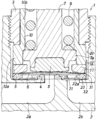
- FIG. 1 is a longitudinal sectional view showing an embodiment of a diaphragm valve and a diaphragm valve seat holder unit according to the present invention.
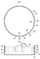
- FIG. 2 is an enlarged view of a seat holder constituting the diaphragm valve seat holder unit, where (a) is a plan view and (b) is a longitudinal sectional view.
- FIG. 3 is an enlarged view of a retainer constituting the diaphragm valve seat holder unit, where (a) is a plan view and (b) is a longitudinal sectional view.
- Diaphragm valve (2): Body, (2a): Fluid inflow passage, (2b): Fluid outflow passage, (4): Seat, (5): Seat holder, (6): Diaphragm, (8 ): Diaphragm holder, (10): Guide tube (diaphragm holding member), (11): Diaphragm holding ring (diaphragm holding member), (12): Retainer, (31): Perimeter wall, (32): Inward flange , (33): Slit, (34): Large arc part, (35): Small arc part, (36): Bent part
- FIG. 1 shows an embodiment of a diaphragm valve according to the present invention.
- the diaphragm valve (1) includes a fluid inflow passage (2a), a fluid outflow passage (2b), and a recess (2c) opened upward.
- a block-shaped body (2) having a cylindrical bonnet (3) whose lower end is screwed to the upper part of the recess (2c) of the body (2) and the peripheral edge of the fluid inflow passage (2a)
- An annular sheet (4) provided on the sheet, a sheet holder (5) that is provided on the outer periphery of the sheet (4) in the body (2) and holds the sheet (4), and is pressed against or separated from the sheet (4)
- the diaphragm (6) that opens and closes the fluid passage (2a) and the diaphragm retainer (8) that presses the center of the diaphragm (6) at the lower end are inserted into the bonnet (3) so as to be movable up and down.
- the diaphragm (6) is disposed between the upper surface of the outer peripheral edge of the diaphragm (6) and the lower end of the guide tube (10) and sandwiches the outer peripheral edge of the diaphragm (6) between the outer peripheral edge of the seat holder (5)
- a holding ring (11) and vertical moving means (not shown) for moving the stem (7) and the diaphragm retainer (8) up and down with compressed air to open and close the fluid passage (2a) are provided.
- the guide tube (10) is composed of a thick part (10a) and a thin part (10b) continuous thereabove.
- the inner circumference of the thick part (10a) is larger in diameter than the inner circumference of the thin part (10b), and the flange part (7a) provided on the stem (7) by the inner circumference of the thick part (10a). It is designed to guide the outer periphery.
- the outer periphery of the thick part (10a) is larger in diameter than the outer periphery of the thin part (10b), and the upper surface of the thick part (10a) (the step surface between the thick part (10a) and the thin part (10b)) ) To receive the lower end surface of the bonnet (3).
- the guide tube (10) presses the diaphragm holding ring (11) downward.
- the guide tube (10) not only guides the stem (7) but also serves as a member for fixing the diaphragm holding ring (11) to the body (2).
- a combination of the ring (11) constitutes a diaphragm holding member that clamps the outer peripheral edge of the diaphragm (6) with the sheet holder (5).
- the above configuration is basically a known configuration, and the diaphragm valve (1) according to the present invention further holds the seat holder (5) in addition to the above configuration, and the lower end portion of the guide cylinder (10) and the diaphragm.
- a retainer (12) detachably attached to the holding ring (11) (diaphragm holding member) is further provided.
- the seat holder (5) and the retainer (12) constitute a diaphragm valve seat holder unit according to the present invention.
- the sheet holder (5) is made of metal and has a perforated disk shape. As shown in detail in FIG. 2, the sheet holder (5) and an inner peripheral edge (21) for holding the sheet (4) and a fluid outflow passage ( It consists of an intermediate annular part (22) in which a plurality of through holes (22b) leading to 2b) are formed, and an outer peripheral part (23) that sandwiches the outer peripheral part of the diaphragm (6).
- the sheet (4) is fitted into the sheet holder (5) from below.
- the retainer (12) is substantially cylindrical and has an inner diameter substantially equal to the outer diameter of the seat (4).
- the lower end of the guide cylinder (10) and the diaphragm holding ring (11) (diaphragm) A peripheral wall (31) fitted to the outer periphery of the holding member), and an inward flange portion (32) provided at a lower end portion of the peripheral wall (31) for receiving the outer peripheral edge portion of the seat holder (5).
- Four pairs of slits (33) extending in the axial direction are provided on the peripheral wall (31), so that the peripheral wall (31) is divided into four large arc portions (34) and four small arc portions (35). It is divided.
- bent portion (36) having an upper end surface located above the upper end of the large arc portion (34) and being bent radially inward and elastically deformable. Is formed.
- the minimum inner diameter of the bent portion (36) is smaller than the outer diameter of the diaphragm holding ring (11) in a free state, so that the diaphragm holding ring (11) can be strongly held.
- the bent portion (36) can be sufficiently elastically deformed, and if it can hold the lower end portion of the guide tube (10) and the diaphragm holding ring (11), it is above the upper end of the large arc portion (34). It is not necessary to have the upper end surface located in the.
- the thickness of the inward flange portion (32) is such that when the seat holder (5) is pressed against the bottom surface of the recess (2c) of the body (2) by the bonnet (3) or the like, the lower end of the seat holder (5) Any thickness may be used as long as the portion can be in contact with the bottom surface of the recess (2c).
- an elastic member (not shown) for biasing the seat holder (5) upward is provided in the inward flange portion (32), and the retainer (12) is held at the lower end of the guide tube (10).
- the lower end of the seat holder (5) does not protrude from the inward flange portion (32) in a state where the seat holder (5) is in contact with the urging force of the elastic member when being fixed to the recess (2c) of the body (2).
- the structure may be such that the sheet holder (5) is pressed, the lower end of the sheet holder (5) protrudes from the inward flange portion (32), and contacts the bottom surface of the recess (2c).
- the retainer (12) only needs to be able to be held by the lower end of the guide tube (10) or the diaphragm holding ring (11) .Therefore, the retainer (12) is provided with a large arc portion (34) and a bent portion (36) for elastic deformation.
- the retainer (12) is formed into a cylindrical shape without a slit, or a slit is formed in a cylindrical shape, and a taper is formed on the outer periphery of the guide tube (10), so that the retainer (12) is formed into a guide tube. It can also be held at the lower end of (10).
- the seat (4) is held in a diaphragm valve seat holder unit including a seat holder (5) and a retainer (12), and is disposed in the body (2).
- the seat (4) is normally replaced when it is used for a certain period of time.
- the retainer (12) is removed to hold the seat holder (5) and the seat (4).
- the attached sheet (4) can be removed.
- the seat (4) is replaced, and if necessary, the seat holder (5) is also replaced.
- the seat (4) is held by the diaphragm valve seat holder unit including the seat holder (5) and the retainer (12). In this state, it is returned to the body (2). In this way, the sheet (4) can be easily replaced. Since the retainer (12) has almost no possibility of plastic deformation, it can usually be used repeatedly, and the plasticity of the retainer (4) makes it easy to replace the sheet (4) over a long period of time. Maintained.
- a diaphragm valve that allows easy exchange of seats, which can contribute to improving the performance of a diaphragm valve that is widely used for opening and closing a fluid passage.
Landscapes
- Engineering & Computer Science (AREA)
- General Engineering & Computer Science (AREA)
- Mechanical Engineering (AREA)
- Physics & Mathematics (AREA)
- Fluid Mechanics (AREA)
- Fluid-Driven Valves (AREA)
- Diaphragms And Bellows (AREA)
- Lift Valve (AREA)
- Details Of Valves (AREA)
Abstract
Description
Claims (4)
- 流体通路が設けられたボディと、ボディに形成された流体通路の周縁に配置されたシートと、ボディに着脱可能に配置されてシートを保持するシートホルダと、シートに押圧・離間されることで流体通路の開閉を行うダイヤフラムと、ダイヤフラムの外周縁部をシートホルダとの間で挟持するダイヤフラム保持部材と、ダイヤフラムの中央部を押圧するダイヤフラム押さえを上下移動させる上下移動手段とを備えているダイヤフラム弁において、
シートホルダを保持するリテーナをさらに備えており、リテーナは、シートホルダを保持した状態でダイヤフラム保持部材に着脱可能に取り付けられていることを特徴とするダイヤフラム弁。 - ボディに形成された流体通路の周縁に配置されるシートを保持するシートホルダと、シートホルダを保持するリテーナとからなり、ダイヤフラムをシートに押圧・離間させることで流体通路の開閉を行うダイヤフラム弁で使用されるダイヤフラム弁用シートホルダユニットであって、リテーナは、略円筒状で、シートホルダの外周縁部を受ける内向きフランジ部を有しているものとされていることを特徴とするダイヤフラム弁用シートホルダユニット。
- リテーナの周壁の上端部に、径方向に弾性変形可能な屈曲部が形成されていることを特徴とする請求項2のダイヤフラム弁用シートホルダユニット。
- リテーナの周壁は、軸方向に延びる複数のスリットが設けられることで、4つ以上の円弧部に分割されており、前記屈曲部は、2つ以上の円弧部に形成されていることを特徴とする請求項2または3のダイヤフラム弁用シートホルダユニット。
Priority Applications (4)
| Application Number | Priority Date | Filing Date | Title |
|---|---|---|---|
| US14/130,064 US9285042B2 (en) | 2011-12-05 | 2012-11-27 | Diaphragm valve and seat holder unit for diaphragm valve |
| KR1020137032470A KR101599117B1 (ko) | 2011-12-05 | 2012-11-27 | 다이어프램 밸브 및 다이어프램 밸브용 시트 홀더 유닛 |
| SG2013086145A SG2013086145A (en) | 2011-12-05 | 2012-11-27 | Diaphragm valve and seat holder unit for diaphragm valve |
| CN201280029552.4A CN103748392B (zh) | 2011-12-05 | 2012-11-27 | 隔膜阀及隔膜阀用阀座保持器单元 |
Applications Claiming Priority (2)
| Application Number | Priority Date | Filing Date | Title |
|---|---|---|---|
| JP2011265392A JP5802532B2 (ja) | 2011-12-05 | 2011-12-05 | ダイヤフラム弁およびダイヤフラム弁用シートホルダユニット |
| JP2011-265392 | 2011-12-05 |
Publications (1)
| Publication Number | Publication Date |
|---|---|
| WO2013084743A1 true WO2013084743A1 (ja) | 2013-06-13 |
Family
ID=48574117
Family Applications (1)
| Application Number | Title | Priority Date | Filing Date |
|---|---|---|---|
| PCT/JP2012/080535 Ceased WO2013084743A1 (ja) | 2011-12-05 | 2012-11-27 | ダイヤフラム弁およびダイヤフラム弁用シートホルダユニット |
Country Status (7)
| Country | Link |
|---|---|
| US (1) | US9285042B2 (ja) |
| JP (1) | JP5802532B2 (ja) |
| KR (1) | KR101599117B1 (ja) |
| CN (1) | CN103748392B (ja) |
| SG (1) | SG2013086145A (ja) |
| TW (1) | TWI633249B (ja) |
| WO (1) | WO2013084743A1 (ja) |
Families Citing this family (18)
| Publication number | Priority date | Publication date | Assignee | Title |
|---|---|---|---|---|
| JP6072648B2 (ja) | 2013-08-12 | 2017-02-01 | 株式会社フジキン | ダイヤフラム弁 |
| KR20170033724A (ko) | 2015-09-17 | 2017-03-27 | 바이트론 인더스트리즈 차이나 | 다이어프램 구조 및 이를 포함하는 다이어프램 밸브 |
| EP3187758B1 (en) * | 2016-01-04 | 2019-04-03 | Danfoss A/S | Capsule for a valve and valve |
| JP6307557B2 (ja) * | 2016-06-17 | 2018-04-04 | Ckd株式会社 | 流体制御弁 |
| US10851898B2 (en) * | 2016-09-29 | 2020-12-01 | Hitachi Metals, Ltd. | Flow control valve and mass flow controller using the same |
| JP6914159B2 (ja) * | 2017-09-26 | 2021-08-04 | 株式会社キッツエスシーティー | ダイヤフラムバルブの組立方法とその組立構造並びにダイヤフラムバルブ |
| KR102341939B1 (ko) * | 2017-11-30 | 2021-12-22 | 가부시키가이샤 후지킨 | 밸브 장치, 이 밸브 장치를 사용한 유체제어장치 및 반도체 제조 장치 |
| WO2019193978A1 (ja) | 2018-04-06 | 2019-10-10 | 株式会社フジキン | バルブ装置および流体制御装置、流体制御方法、半導体製造装置及び半導体製造方法 |
| CN110735930A (zh) * | 2018-07-18 | 2020-01-31 | 北京七星华创流量计有限公司 | 气体流量调节装置及质量流量控制器 |
| US20210018103A1 (en) * | 2018-09-26 | 2021-01-21 | Fujikin Incorporated | Diaphragm valve |
| WO2020066585A1 (ja) * | 2018-09-27 | 2020-04-02 | 株式会社フジキン | バルブ、バルブの弁体ユニットの交換方法、および、バルブの組立方法 |
| KR20210074377A (ko) * | 2018-10-26 | 2021-06-21 | 가부시키가이샤 후지킨 | 밸브 장치 및 가스 공급 시스템 |
| CN112930454A (zh) * | 2018-10-26 | 2021-06-08 | 株式会社富士金 | 阀装置和气体供给系统 |
| WO2021192753A1 (ja) * | 2020-03-26 | 2021-09-30 | 株式会社フジキン | バルブ装置 |
| TWI770615B (zh) * | 2020-09-22 | 2022-07-11 | 和正豐科技股份有限公司 | 氟樹脂膜片閥 |
| KR20230109746A (ko) * | 2020-11-30 | 2023-07-20 | 파커-한니핀 코포레이션 | 이중 축 시트 리테이너 |
| CN114643306B (zh) * | 2022-05-19 | 2022-08-02 | 成都成高阀门有限公司 | 一种阀门的阀座压制工装 |
| JP2025014385A (ja) * | 2023-07-18 | 2025-01-30 | Ckd株式会社 | 流体制御弁 |
Citations (7)
| Publication number | Priority date | Publication date | Assignee | Title |
|---|---|---|---|---|
| JPH06193747A (ja) * | 1992-12-25 | 1994-07-15 | Hitachi Metals Ltd | メタルダイアフラム弁 |
| JPH06341560A (ja) * | 1993-06-02 | 1994-12-13 | Kiyohara Masako | ダイヤフラム弁 |
| JPH1026240A (ja) * | 1996-07-10 | 1998-01-27 | Benkan Corp | リーク弁 |
| JPH10332003A (ja) * | 1997-05-28 | 1998-12-15 | Ckd Corp | ガス制御バルブ |
| JP2003042314A (ja) * | 2001-07-31 | 2003-02-13 | Fujikin Inc | ダイヤフラム弁 |
| JP2003322263A (ja) * | 2002-05-07 | 2003-11-14 | Hitachi Metals Ltd | メタルダイヤフラム弁の弁座シートの固定方法及びその固定冶具 |
| JP2010144765A (ja) * | 2008-12-16 | 2010-07-01 | Hamlet Motoyama Japan:Kk | ダイヤフラム弁 |
Family Cites Families (15)
| Publication number | Priority date | Publication date | Assignee | Title |
|---|---|---|---|---|
| JPS63115970A (ja) * | 1986-10-31 | 1988-05-20 | Motoyama Seisakusho:Kk | ダイヤフラム弁 |
| JP3505589B2 (ja) * | 1992-04-20 | 2004-03-08 | 清原 まさ子 | 管継手用リテーナ |
| US5366261A (en) * | 1992-04-27 | 1994-11-22 | Fujikin Incorporated | Pipe joint with a gasket retainer |
| US5215286A (en) * | 1992-05-26 | 1993-06-01 | Nupro Company | High pressure diaphragm valve |
| JP3372091B2 (ja) * | 1993-11-15 | 2003-01-27 | 株式会社本山製作所 | ダイヤフラム弁構造 |
| JP3661040B2 (ja) * | 1995-05-31 | 2005-06-15 | 忠弘 大見 | 流体制御装置 |
| JP3605705B2 (ja) * | 1995-07-19 | 2004-12-22 | 株式会社フジキン | 流体制御器 |
| JP3739500B2 (ja) * | 1996-09-30 | 2006-01-25 | 株式会社キッツエスシーティー | 集積化ガスパネル用フィルターユニット |
| US6073646A (en) * | 1996-09-30 | 2000-06-13 | Benkan Corporation | Gas controlling device for integration |
| US6508266B2 (en) * | 2000-03-31 | 2003-01-21 | Toyo Stainless Steel Industries Co., Ltd. | Diaphragm valve |
| EP1300619B1 (en) * | 2000-06-05 | 2006-08-02 | Fujikin Incorporated | Orifice-built-in valve |
| JP4119275B2 (ja) * | 2003-02-18 | 2008-07-16 | 忠弘 大見 | 真空排気系用のダイヤフラム弁 |
| EP2003379A1 (en) * | 2007-06-12 | 2008-12-17 | Luxembourg Patent Company S.A. | High pressure diaphragm valve with exchangeable seat assembly |
| CN201502743U (zh) * | 2009-09-21 | 2010-06-09 | 倪商伟 | 轻便型隔膜阀 |
| CN201575189U (zh) * | 2009-09-30 | 2010-09-08 | 周庆男 | 气动衬塑隔膜阀 |
-
2011
- 2011-12-05 JP JP2011265392A patent/JP5802532B2/ja active Active
-
2012
- 2012-11-27 KR KR1020137032470A patent/KR101599117B1/ko active Active
- 2012-11-27 WO PCT/JP2012/080535 patent/WO2013084743A1/ja not_active Ceased
- 2012-11-27 SG SG2013086145A patent/SG2013086145A/en unknown
- 2012-11-27 CN CN201280029552.4A patent/CN103748392B/zh not_active Expired - Fee Related
- 2012-11-27 US US14/130,064 patent/US9285042B2/en active Active
- 2012-12-04 TW TW101145375A patent/TWI633249B/zh active
Patent Citations (7)
| Publication number | Priority date | Publication date | Assignee | Title |
|---|---|---|---|---|
| JPH06193747A (ja) * | 1992-12-25 | 1994-07-15 | Hitachi Metals Ltd | メタルダイアフラム弁 |
| JPH06341560A (ja) * | 1993-06-02 | 1994-12-13 | Kiyohara Masako | ダイヤフラム弁 |
| JPH1026240A (ja) * | 1996-07-10 | 1998-01-27 | Benkan Corp | リーク弁 |
| JPH10332003A (ja) * | 1997-05-28 | 1998-12-15 | Ckd Corp | ガス制御バルブ |
| JP2003042314A (ja) * | 2001-07-31 | 2003-02-13 | Fujikin Inc | ダイヤフラム弁 |
| JP2003322263A (ja) * | 2002-05-07 | 2003-11-14 | Hitachi Metals Ltd | メタルダイヤフラム弁の弁座シートの固定方法及びその固定冶具 |
| JP2010144765A (ja) * | 2008-12-16 | 2010-07-01 | Hamlet Motoyama Japan:Kk | ダイヤフラム弁 |
Also Published As
| Publication number | Publication date |
|---|---|
| SG2013086145A (en) | 2014-09-26 |
| KR101599117B1 (ko) | 2016-03-02 |
| TWI633249B (zh) | 2018-08-21 |
| CN103748392A (zh) | 2014-04-23 |
| TW201341697A (zh) | 2013-10-16 |
| US9285042B2 (en) | 2016-03-15 |
| KR20140005368A (ko) | 2014-01-14 |
| JP5802532B2 (ja) | 2015-10-28 |
| JP2013117269A (ja) | 2013-06-13 |
| US20140319403A1 (en) | 2014-10-30 |
| CN103748392B (zh) | 2016-04-27 |
Similar Documents
| Publication | Publication Date | Title |
|---|---|---|
| JP5802532B2 (ja) | ダイヤフラム弁およびダイヤフラム弁用シートホルダユニット | |
| WO2013084744A1 (ja) | ダイヤフラム弁 | |
| JP6072648B2 (ja) | ダイヤフラム弁 | |
| JP5933370B2 (ja) | ダイヤフラム弁 | |
| TWI684721B (zh) | 流體控制器 | |
| JP5978035B2 (ja) | 流体制御器用アクチュエータ | |
| EP1996850B1 (en) | Valve with a springy diaphragm | |
| JP6564593B2 (ja) | ダイヤフラム弁 | |
| CN105008777A (zh) | 隔膜阀 | |
| JP2010159790A (ja) | ダイヤフラム弁用ダイヤフラム押さえおよびこれを備えたダイヤフラム弁 | |
| US20090014077A1 (en) | One piece double membrane diaphragm valve | |
| KR101829864B1 (ko) | 디스크 상부에 탄성체가 구비된 안전밸브 | |
| JP5764315B2 (ja) | ダイヤフラム弁 | |
| JP2015048862A (ja) | ダイヤフラム弁 | |
| JP5022971B2 (ja) | 圧力調整器 |
Legal Events
| Date | Code | Title | Description |
|---|---|---|---|
| WWE | Wipo information: entry into national phase |
Ref document number: 201280029552.4 Country of ref document: CN |
|
| 121 | Ep: the epo has been informed by wipo that ep was designated in this application |
Ref document number: 12854901 Country of ref document: EP Kind code of ref document: A1 |
|
| ENP | Entry into the national phase |
Ref document number: 20137032470 Country of ref document: KR Kind code of ref document: A |
|
| WWE | Wipo information: entry into national phase |
Ref document number: 14130064 Country of ref document: US |
|
| NENP | Non-entry into the national phase |
Ref country code: DE |
|
| 122 | Ep: pct application non-entry in european phase |
Ref document number: 12854901 Country of ref document: EP Kind code of ref document: A1 |