WO2013084540A1 - 通帳類取扱装置 - Google Patents
通帳類取扱装置 Download PDFInfo
- Publication number
- WO2013084540A1 WO2013084540A1 PCT/JP2012/070070 JP2012070070W WO2013084540A1 WO 2013084540 A1 WO2013084540 A1 WO 2013084540A1 JP 2012070070 W JP2012070070 W JP 2012070070W WO 2013084540 A1 WO2013084540 A1 WO 2013084540A1
- Authority
- WO
- WIPO (PCT)
- Prior art keywords
- reading
- passbook
- magnetic
- identification information
- mechanism unit
- Prior art date
- Legal status (The legal status is an assumption and is not a legal conclusion. Google has not performed a legal analysis and makes no representation as to the accuracy of the status listed.)
- Ceased
Links
Images








Classifications
-
- G—PHYSICS
- G06—COMPUTING OR CALCULATING; COUNTING
- G06K—GRAPHICAL DATA READING; PRESENTATION OF DATA; RECORD CARRIERS; HANDLING RECORD CARRIERS
- G06K7/00—Methods or arrangements for sensing record carriers, e.g. for reading patterns
- G06K7/08—Methods or arrangements for sensing record carriers, e.g. for reading patterns by means detecting the change of an electrostatic or magnetic field, e.g. by detecting change of capacitance between electrodes
- G06K7/082—Methods or arrangements for sensing record carriers, e.g. for reading patterns by means detecting the change of an electrostatic or magnetic field, e.g. by detecting change of capacitance between electrodes using inductive or magnetic sensors
- G06K7/087—Methods or arrangements for sensing record carriers, e.g. for reading patterns by means detecting the change of an electrostatic or magnetic field, e.g. by detecting change of capacitance between electrodes using inductive or magnetic sensors flux-sensitive, e.g. magnetic, detectors
Definitions
- the present invention relates to a bankbook handling apparatus.
- Patent Document 1 the type of passbook is specified by determining whether or not a barcode attached to a passbook can be recognized at a predetermined position, and a magnetic stripe attached to the passbook of that type is read. Is disclosed.
- Patent Document 1 the type of passbook is specified by recognizing a bar code attached to the passbook, and the magnetic stripe is read.
- the method described in Patent Document 1 is based on the premise that after reading the barcode attached to the transaction content printing surface side of the passbook, the magnetic stripe attached to the passbook cover side is read. is there. That is, it is not assumed that both the barcode and the magnetic stripe are attached to the passbook cover.
- the magnetic head When handling a passbook with both barcodes and magnetic stripes on the cover side, the magnetic head that reads and writes the magnetic data recorded on the magnetic stripe and the barcodes are read and written. By mounting the devices close to each other, it is possible to read barcodes and magnetic stripes with a simple and space-saving mechanism.
- the magnetic head when reading magnetic data, the magnetic head needs to be in contact with the magnetic stripe. Therefore, if the magnetic head and a device for reading a bar code are mounted close to each other, the device is magnetic when reading the bar code. It may come into contact with the head. Due to such contact, magnetic powder or other dirt on the magnetic stripe attached to the magnetic head adheres to the device, and the cover of the passbook or the device itself is soiled. There was a problem that it caused a decline and misrecognition.
- the present invention has been made in view of the above, and an object thereof is to provide a device for reading a barcode and a passbook handling device that does not deface the cover of the passbook.
- the passbook handling apparatus includes a passbook with magnetic identification information and other identification information different from the magnetic identification information attached to the cover side.
- a passbook handling device for handling the magnetic identification mechanism, the magnetic reading mechanism section for reading the magnetic identification information, the reading mechanism section for reading the other identification information, the magnetic reading mechanism section, and the reading mechanism section.
- a moving mechanism for moving the information or the other identification information in the reading direction, a guide mechanism for arranging the magnetic reading mechanism away from the passbooks, and the reading mechanism for the other identification information.
- a control unit that moves the magnetic reading mechanism along the guide mechanism so as not to contact the passbooks.
- FIG. 1 It is a figure which shows the example of the barcode or magnetic stripe attached
- FIG. 6 is a flowchart showing a processing procedure of a reading process shown in FIG. 5.
- FIG. 1 is a diagram showing a configuration of a passbook entry device 100 according to the present embodiment.
- the passbook entry device 100 includes a transport mechanism unit 101, a magnetic data processing mechanism unit 102, a passbook printing surface side barcode reading mechanism unit 103, a passbook cover side barcode reading mechanism unit 104, The printing mechanism unit 105, the image data capturing mechanism unit 106, the page change mechanism unit 107, the passbook issuing mechanism unit 108, the passbook collection mechanism unit 109, the control unit 110, and the communication unit 111 are provided. It is configured.
- the transport mechanism unit 101 transports the passbook 1 inserted from the insertion port 112 and the passbook 1 fed from the passbook issuing mechanism unit 108 to each mechanism unit corresponding to the content of the bookkeeping process through the transport path. Further, the transport mechanism unit 101 transports the passbook 1 for which the bookkeeping process has been completed or the passbook 1 issued from the passbook issuing mechanism unit 108 to the insertion port 112 through the transport path, and returns the passbook 1.
- the magnetic data processing mechanism unit 102 accesses the magnetic data recorded in the magnetic stripe 2 provided in the passbook 1, and reads and writes account information such as the account number and the number of final print lines.
- the passbook printing surface side barcode reading mechanism unit 103 reads the passbook printing surface side barcode 3 representing the page information such as the page number of the bankbook 1 printed on the surface on which the transaction contents of the passbook 1 are printed.
- the passbook cover side barcode reading mechanism unit 104 reads the passbook cover side barcode 4 representing the passbook information such as the account number printed on the cover side of the passbook 1 and the passbook issue number.
- the magnetic data processing mechanism unit 102 and the passbook cover side barcode reading mechanism unit 104 are provided close to the lower side of the transport mechanism unit 101. It is a space-saving and simple mechanism.
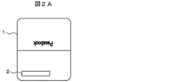
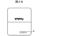
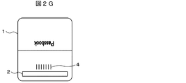
- FIG. 2A to 2G are diagrams showing examples of barcodes and magnetic stripes attached to the passbook 1.
- FIG. 2A shows an example in which a magnetic stripe is attached to one of the cover side of the passbook 1.
- FIG. 2B shows an example in which the passbook cover side barcode 4 is attached to one of the cover side of the passbook 1.
- FIG. 2C shows an example where the passbook cover side barcode 4 is attached to the other one of the cover side of the passbook 1.
- FIG. 2D shows an example in which the magnetic stripe 2 is attached to one of the cover side of the passbook 1 and the passbook cover side bar code 4 is attached to the other one.
- FIG. 2E shows an example in which the passbook print surface side barcode 3 is attached to one of the passbook print surface side of the passbook 1.
- FIG. 2F shows an example in which the magnetic stripe 2 and the passbook cover side barcode 4 are attached to one side of the cover side of the passbook 1 in the reading direction.
- FIG. 2G shows an example in which the magnetic stripe 2 and the bar code cover-side barcode 4 are attached to one side on the cover side of the passbook 1 in the conveyance direction of the passbook 1.
- the passbook there are various positions on the passbook to which the magnetic stripe 2, the passbook printing surface side barcode 3, or the passbook cover side barcode 4 is attached.
- the barcode sensor 203 (described later) reads the passbook cover side barcode 4.
- the magnetic head 201 comes into contact with the magnetic sensor 201 and the magnetic powder of the magnetic stripe attached to the magnetic head 201 and other dirts easily adhere to the barcode sensor 203.
- the barcode sensor 203 (described later) and the cover of the passbook 1 may be soiled, leading to a decrease in reading accuracy of the passbook cover-side barcode 4 and erroneous recognition.
- the bar code sensor 203 reads the bar code with the magnetic head 201 kept away from the bar code sensor 203.
- the printing mechanism unit 105 prints transaction information indicating transaction details of the deposit / withdrawal result on a predetermined page of the book 1.
- the image data fetching mechanism unit 106 takes in the image data on the passbook printing surface side of the passbook 1, so that the number of lines of transaction information printed on the page (for example, up to the number of lines on the passbook 1 page) Detect whether the content is printed). Further, the image data fetching mechanism unit 106 reads the passbook printing surface side barcode 3 printed on the passbook 1, and after the printing mechanism unit 105 prints the transaction information described above, the ink ribbon needs to be replaced. The print density for checking whether or not is detected.
- the page change mechanism unit 107 turns the passbook 1 that has been transported by the transport mechanism unit 101.
- the passbook issuing mechanism unit 108 sends out a new passbook 1 to the transport mechanism unit 101 in order to issue a new passbook for new issue stored in advance.
- the passbook collection mechanism unit 109 collects the passbook 1 that has been forgotten after the completion of the bookkeeping process, or temporarily saves the old passbook when the new passbook is issued.
- the control part 110 controls each mechanism part which comprises the passbook bookkeeping apparatus 100.
- the communication unit 111 transmits and receives various information necessary for the transaction such as the transaction information and the account information described above to and from the host control device 5.
- FIG. 3 is a block diagram showing a functional configuration of the bankbook entry device 100 shown in FIG.
- the passbook entry device 100 functionally includes a transport mechanism unit 101, a magnetic data processing mechanism unit 102, a passbook printing surface side barcode reading mechanism unit 103, and a passbook cover side barcode reading.
- the configuration of the magnetic data processing mechanism unit 102 and the passbook cover side barcode reading mechanism unit 104 will be described in more detail.
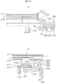
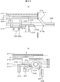
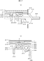
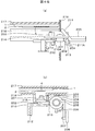
- 4A (a) to 4 (b) are diagrams showing an example of the transition of the configuration and operation of the magnetic data processing mechanism unit 102 and the passbook cover side barcode reading mechanism unit 104 described above.
- 4A (a), 4B (a), 4C (a), 4D (a), 4E (a), 4F (a), and 4G (a) each of these mechanism parts is on the side of the insertion port 12. It is a front view at the time of seeing.
- 4A (b), 4B (b), 4C (b), 4D (b), 4E (b), 4F (b), and 4G (b) are respectively front views when viewed from the reading direction. It is a side view corresponding to.
- the magnetic data processing mechanism unit 102 and the passbook cover side barcode reading mechanism unit 104 may be collectively referred to as an information reading mechanism unit.
- the information reading mechanism unit includes a magnetic head 201 that reads and writes magnetic data in contact with the magnetic stripe 2 and a retraction guide 211 described later.
- Head carrier 202 for holding magnetic head 201 sandwiched from both sides by arms each having claws 213 and 214 for holding in a retracted state, and a prescribed range from the surface of the passbook cover side barcode 4 to the light emitting / receiving surface
- a bar code sensor 203 for reading the bar code 4 on the passbook cover side, and a center part for supporting and holding the bar code sensor 203 from the center portion to the outside.
- a carrier support that has an extended arm and supports the posture of the head carrier 202 by sandwiching the head carrier 202 from both sides.
- a lead screw 205 that is driven by an actuator such as a motor (not shown) to move the carrier support 204 in the axial direction, and a spring that applies a biasing force to the head carrier 202 in a direction to bring the magnetic head 201 closer to the magnetic stripe 2 206 and the carrier support 204 are restricted from rotating around the axis of the lead screw 205, and follow the roller guide 208 to be described later to assist the movement of the carrier support 204 in the direction perpendicular to the conveyance direction of the passbook 1.
- an actuator such as a motor (not shown) to move the carrier support 204 in the axial direction
- a spring that applies a biasing force to the head carrier 202 in a direction to bring the magnetic head 201 closer to the magnetic stripe 2 206 and the carrier support 204 are restricted from rotating around the axis of the lead screw 205, and follow the roller guide 208 to be described later to assist the movement of the carrier support 204 in the direction perpendicular to the conveyance direction of the passbook 1.
- the head carrier 202 is moved in the axial direction of the lead screw 205 by the roller 207, the roller guide 208 that guides the movement of the roller 207, the nut 209 that meshes with the lead screw 205, and the spring 212 that applies an upward biasing force.
- Head carry in case A control guide 210 that regulates the vertical position of 202, and a retraction guide 211 for retreating the head carrier 202 before movement to a retraction position in a state where the spring 206 stores urging force. Yes.
- the upper conveyance guide 217 and the lower conveyance guide 218 that convey the bankbook 1 to be conveyed in the traveling direction, and the reference conveyance guide 216 for defining the reference plane of these conveyance guides constitute a conveyance path of the bankbook 1.
- a part of the lower conveyance guide 218 is provided with a conveyance path opening for allowing the magnetic head 201 and the barcode sensor 203 to access the passbook 1, and the conveyance path is opened and closed in the conveyance path.
- a shutter 215 is provided.
- the carrier support 204 and the head carrier 202 move integrally in the axial direction of the lead screw 205 (that is, the data reading direction) and are held by the arm of the carrier support 204 and the bar code sensor 203 and the head.
- the magnetic head 201 held between the arms of the carrier 202 also moves together with them.
- the lead screw 205 can be rotated by an actuator such as a single motor, so that the current configuration can be maintained without the need for a separate actuator. It has become.
- the information reading mechanism unit includes a moving mechanism for moving the carrier support 204 in the axial direction, such as a lead screw 205, a magnetic stripe 201 of the magnetic head 201 and the passbook 1, such as a control guide 210 and a retracting guide 211, and the like.
- Guide mechanism for arranging the magnetic head 201 so as to control contact with the passbook cover side barcode 4 of the passbook 1 that is, arranging the magnetic head 201 away from the passbook cover side barcode 4 of the passbook 1). Therefore, the barcode sensor 203 and the cover of the passbook 1 are not soiled while maintaining a space-saving and simple mechanism.
- the control guide 210 is long enough to maintain the magnetic head 201 pressed down at least while the bar code sensor 203 reads the passbook cover side bar code 4.
- the magnetic head 201 is maintained at a position away from the bankbook 1.
- an end 210A on the side facing the traveling direction of the head carrier 202 (opposite to the traveling direction) has an acute angle, and the tip of the acute angle has an arm of the head carrier 202. It arrange
- the entire head carrier 202 also enters the lower side of the control guide 210 and can be moved away from the positions of the passbook cover side barcode 4 and the magnetic stripe 2.
- the end 210A of the control guide 210 described above is described as having an acute angle. However, if the tip is located slightly above the upper end of the head carrier 202, the end is rounded. It may have a cracked shape.
- the width of the edge portion 211A of the retracting guide 211 which is one end of the control guide 210 in the traveling direction side of the head carrier 202, is larger than the width of the claws 213 and 214 of the respective arms of the head carrier 202. It is configured to be slightly narrower. The reason is that when the head carrier 202 moves in the traveling direction, at least one of the claw 213 located in the inner direction of the conveyance path or the claw 214 located in the outer direction of the conveyance path is controlled by the control guide 210 or the retraction guide. This is because the state needs to be in contact with 211.
- the head carrier 202 is biased by the elastic force of the spring 206 when it passes over the gap between the end portion 210A and the edge portion 211A described above, and the passbook cover side barcode 4 And can move smoothly along the traveling direction without approaching the position of the magnetic stripe 2.
- the arm length of the carrier support 204 and the arm length of the head carrier 202 are substantially the same so that the magnetic head 201 and the bar code sensor 203 are arranged in the reading direction.
- the length is such that both of them rotate coaxially.
- the magnetic head 201 and the barcode sensor are changed by changing the arm length of each part described above. It is good also as arrange
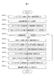
- FIG. 5 is a flowchart showing a processing procedure of a bookkeeping process performed by the passbook bookkeeping apparatus 100.
- the bankbook 1 is inserted in a state where it is not known whether it has the magnetic stripe 2 or the cover-side barcode 4. If the inserted bankbook 1 has the magnetic stripe 2, the magnetic data processing mechanism 102 reads the magnetic data by the magnetic head 201 to obtain account information, and has the cover-side barcode 4. If so, the passbook cover side bar code reading mechanism unit 104 reads the bar code by the bar code sensor 203 to acquire the passbook information, and proceeds to the subsequent processing.
- the transport mechanism unit 101 reads the passbook 1 as magnetic data.
- the magnetic data processing mechanism unit 102 and the passbook cover side bar code reading mechanism unit 104 read (read) the magnetic stripe or the passbook cover side bar code.
- the account information such as the account number and account holder included in the read magnetic stripe 2 or passbook cover side barcode 4 is acquired (step S502), and the communication unit 111 acquires the acquired account information. Is transmitted to the host controller 5 (step S503).
- the reading process performed in step S502 will be described.
- FIG. 6 is a flowchart showing the processing procedure of the reading process described above.
- the passbook entry device 100 is configured to print the cover-side barcode 4 in the passbook transport direction on the assumption that the transport mechanism 101 first prints the cover-side barcode 4 of the passbook 1.
- the bankbook 1 is transported so that the position matches the reading position of the barcode sensor 203, and the stop position of the bankbook 1 is adjusted to the barcode sensor 203 (step S601).
- the transport mechanism unit 101 opens the shutter 215 provided at the transport path opening (step S602).
- the carrier support 204 is in a state of being retracted to a predetermined position outside the conveyance path. More specifically, since the retraction guide 211 is in a state where the claws 213 and 214 of the head carrier 202 are pressed, the urging force by the spring 206 is not released in the rotational direction of the arm of the head carrier 202, and the magnetic head 201 is in a state of being retracted at a position lowered downward from the conveyance path opening (FIGS. 4A (a) and (b)).
- the reading mechanism unit rotates the lead screw 205 to move the carrier support 204 evacuated to a predetermined position outside the conveyance path in the conveyance path inner side (reading direction) (step S603).
- the operation at this time will be described.
- the claws 213 and 214 of the head carrier 202 are pressed by the retraction guide 211, so the magnetic head 201 is lowered below the conveyance path opening.
- the magnetic head 201 supported by the head carrier 202 moves with the carrier support 204, and the magnetic head 201 passes below the reference conveyance guide 216 and does not contact or approach the bankbook 1. Move gradually inward.
- the claw 213 of the head carrier 202 held by the retraction guide 211 tends to come off from the retraction guide 211, but the other nail 214. Is held by the control guide 210 (FIGS. 4B (a) and (b)). Therefore, similarly to the retracted state, the head carrier 202 can continue to move in the advancing direction while keeping the magnetic head 201 lowered downward from the conveyance path opening.
- the magnetic head 201 sandwiched between the head carriers 202 is exposed to the conveyance path opening side by moving the carrier support 204 while being pushed down similarly to the retracted state at the start of processing. There is no. Therefore, the barcode sensor 203 can reliably read the cover-side barcode 4 without bringing the magnetic head 204 close to or in contact with the passbook 1 (FIGS. 4C (a) and (b)).
- the reading mechanism unit is moved to a position exceeding the printing position of the passbook cover side barcode 4 printed on the passbook 1 on the carrier support 204, and the passbook cover side barcode reading mechanism unit 104 is controlled by the barcode sensor 203.
- An attempt is made to read the barcode 4 (step S604).
- the passbook cover-side barcode reading mechanism 104 can read the passbook cover-side barcode 4 (step S605; Yes)
- the passbook 1 conveyed is not the magnetic stripe 2 but the passbook cover-side barcode. Since it is determined that the bankbook has 4, the process proceeds to step S611.
- the reading mechanism unit stops the movement of the carrier support 204, rotates the lead screw 205 in the reverse direction to move the carrier support 204 to a predetermined retracted position outside the conveyance path (step S611), and then closes the shutter 215.
- step S612 the reading process shown in FIG. 6 is terminated, and the process returns to the bookkeeping process shown in FIG. 5 and proceeds to the next process such as transaction content printing.
- the passbook cover side barcode reading mechanism unit 104 cannot read the passbook cover side barcode 4 (step S605; No)
- the passbook 1 conveyed is not a passbook cover side barcode 4 but a magnetic stripe. 2 is a passbook
- the reading mechanism unit subsequently tries to read the magnetic data. At this time, before determining that the bankbook has the magnetic stripe 2, a retry of reading the banknote cover side barcode 4 may be attempted.
- the reading mechanism unit moves the bankbook 1 by the transport mechanism unit 101 so that the position of the magnetic stripe 2 viewed from the transport direction of the bankbook 1 provided with the magnetic stripe 2 matches the reading position and the writing position of the magnetic head 201. Then, the stop position of the bankbook 1 is set to the magnetic head 201 (S606).
- the reading mechanism section further rotates the lead screw 205 from this state to move the claw 213 of the head carrier 202 to a position where it is disengaged from the control guide 210 as shown in FIGS. 4D (a) and (b).
- the claw 213 pushed down by the control guide 210 is released upward.
- the head carrier 202 rises in the direction of the conveyance path opening, and the magnetic head 201 can be brought into contact with the magnetic stripe 2 of the book 1 (step S607).
- the reading mechanism unit further rotates the lead screw 205 to move the carrier support 204, and moves the magnetic head 201.
- the magnetic data is read and written to the starting position (step S608, FIGS. 4E (a) and (b)).
- the reading mechanism unit reversely rotates the lead screw 205 to move the carrier support 204 to the retracted position side (that is, the magnetic data reading direction) (step S609), and the magnetic data processing mechanism unit 102 is moved by the magnetic head 201.
- the magnetic data of the magnetic stripe 2 attached to the bankbook 1 is read (step S610, FIG. 4F (a), (b)).
- the reading mechanism unit reads the magnetic data of the magnetic stripe 2 and moves the carrier support 204 as it is in the reading direction
- the claw 213 of the head carrier 202 is pushed by the retraction guide 210 and the head carrier 202 is moved to the conveyance path opening. It begins to fall below.
- the lower side of the claw 214 of the head carrier 202 contacts the upper portion of the control guide 210.
- the control guide 210 is urged upward by the spring 212, but the control guide 210 in contact with the lower side of the claw 214 is pushed down by the claw 214 and moves so as to escape downward.
- the carrier support 204 can escape the reference conveyance guide 216 downward while the head carrier 202 is lowered, and can return to a predetermined retracted position (step S611, FIG. 4G (a), (b)).
- step S612 the reading mechanism section closes the shutter 215 (step S612), and then ends the reading process shown in FIG. 6, and returns to the bookkeeping process shown in FIG. To do.
- step S612 all the processes in the reading process shown in FIG. 6 are completed. Subsequently, returning to FIG. 5, the processing after step S503 will be described.
- the communication unit 111 transmits the acquired account information to the host control device 5 (step S503), the communication unit 111 receives transaction data corresponding to the account information from the host control device 5 (step S504). By detecting how many lines of transaction contents are printed on the page of the passbook 1 where the contents of the transaction are printed at the present time, it is determined from which line of the page of the passbook 1 printing is started (step S505). Then, the transaction content recorded in the transaction data received from the host controller 5 is printed (step S506).
- step S507 determines whether or not the printing of the transaction content recorded in the transaction data is completed. If so (step S507; Yes), the process proceeds to step S517.
- step S507 determines that printing of the transaction content recorded in the transaction data has not been completed.
- step S508 determines whether printing has been completed on the last line of the page. If it is determined that the last line of the page has not been printed (step S508) (step S508; No), the process returns to step S506 to continue the transaction content printing.
- step S508 If the printing mechanism unit 105 determines that the last line of the page has been printed (step S508; Yes), the printing mechanism unit 105 further determines whether the page is the last page (step S509), and the page is the last page. When it determines with there (step S509; Yes), it progresses to step S513.
- step S509 when the printing mechanism unit 105 determines that the page is not the last page (step S509; No), the page changing mechanism unit 107 turns the page (step S510), and the passbook printing surface side barcode reading mechanism unit. 103 reads the passbook printing surface side barcode 3 (step S511), and the page changing mechanism 107 determines whether the page turning is completed (step S512).
- step S512 determines that the page turning is not completed (step S512; No)
- step S512 determines that the page turning mechanism unit 107 returns to step S510 to continue the page turning and determines that the page turning is completed (step S512; Yes)
- the process returns to step S506 to continue the transaction content printing.
- step S509 when the printing mechanism unit 105 determines that the page is the last page (step S509; Yes), it is determined that there are no pages that can be printed on the passbook 1, and the transport mechanism unit 101 sets a new passbook 1.
- the old bankbook is temporarily saved for issuance (step S613).
- the passbook issuing mechanism unit 108 issues a new passbook (step S514)
- the printing mechanism unit 105 prints the transaction contents (step S515)
- the transport mechanism unit 101 transports the new passbook and the old passbook to the insertion slot 112. Then, these passbooks are returned (steps S516 and S517).
- the passbook collection mechanism unit 109 determines whether or not the returned passbook has been forgotten (step S518). If it is determined that the returned passbook has been forgotten (step S518; Yes), the passbook is collected. (Step S519), and the bookkeeping process is terminated (Step S520). If the passbook collection mechanism unit 109 does not determine that the returned passbook has been forgotten (step S518; No), the bookkeeping process is terminated without doing anything. When the process of step S520 is finished, all the bookkeeping processes shown in FIG. 5 are finished.
- the magnetic data processing mechanism unit 102 that reads the magnetic stripe 2 in the passbook entry device 100 that handles the passbooks with the magnetic stripe 2 and the passbook cover side barcode 4 different from the magnetic stripe 2 attached to the cover side.
- the passbook cover side barcode reading mechanism 104 for reading the passbook cover side barcode 4, the magnetic data processing mechanism 102, and the passbook cover side barcode reading mechanism 104, the magnetic stripe 2 or the passbook cover side barcode 4 A lead screw 5 that moves in the reading direction, and a guide mechanism unit (control guide 210 and retraction guide 211) for disposing the magnetic data processing mechanism unit 102 (magnetic head 201) away from the books.
- the control unit 110 has a passbook cover side barcode reading mechanism 104 (barcode sensor 203) has a passbook cover side barcode. Is read, the magnetic data processing mechanism 102 (magnetic head 201) is moved along the guide mechanism (the control guide 210 and the retracting guide 211) so as not to contact the books, so that a magnetic stripe is formed on the passbook cover side.
- the barcode is placed close to the magnetic head as in the reading mechanism section.
- the bankbook having means for replacing the magnetic stripe 2 is described as a bankbook printed with the bankbook cover side barcode 4 that is read by the barcode sensor 203.
- an IC (Integrated Circuit) chip is used.
- a bankbook or the like in which an IC chip that is read by a reader is embedded may be used.
- the position control of the head carrier 202 may be performed by an actuator such as a solenoid instead of the retraction guide 211 or the control guide 210.
Landscapes
- Engineering & Computer Science (AREA)
- Artificial Intelligence (AREA)
- Computer Vision & Pattern Recognition (AREA)
- Physics & Mathematics (AREA)
- General Physics & Mathematics (AREA)
- Theoretical Computer Science (AREA)
- Financial Or Insurance-Related Operations Such As Payment And Settlement (AREA)
Abstract
バーコードを読み取るためのデバイスや通帳の表紙を汚損させることのない通帳類取扱装置を提供する。磁気識別情報と、磁気識別情報とは異なる他の識別情報とが表紙側に付された通帳類を取り扱う通帳類取扱装置であって、磁気識別情報を読取る磁気読取り機構部と、他の識別情報を読取る読取り機構部と、磁気読取り機構部と読取り機構部とを、磁気識別情報または他の識別情報の読取方向に移動させる移動機構部と、磁気読取り機構部を通帳類から離間して配置するためのガイド機構部と、読取り機構部が他の識別情報を読取る際に、磁気読取り機構部を通帳類に接触させないようにガイド機構部に沿って移動させる制御部と、を備える。
Description
本発明は、通帳類取扱装置に関する。
従来から、通帳類に付されたバーコードおよび磁気ストライプを読み取ることが可能な様々な通帳類取引装置が存在する。例えば、特許文献1では、通帳に付されたバーコードが所定の位置で認識可能か否かを判別することによって通帳の種類を特定し、その種類の通帳に付されている磁気ストライプを読み取る技術が開示されている。
上述した特許文献1では、通帳の種類を、その通帳に付されたバーコードを認識することにより特定し、磁気ストライプを読取っている。しかしながら、上記特許文献1に記載された方法は、通帳の取引内容印字面側に付されたバーコードを読み取った上で、通帳表紙側に付された磁気ストライプを読み取ることを前提とするものである。すなわち、バーコードおよび磁気ストライプの両方が通帳表紙側に付されていることを前提とするものではない。
バーコードおよび磁気ストライプの両方が表紙側に付されている通帳を一つの装置で取り扱う場合、磁気ストライプに記録された磁気データの読取りや書込みを行う磁気ヘッドと、バーコードの読取りや書込みを行うデバイスとを近接して実装することにより、省スペースかつ簡素な機構で、バーコードおよび磁気ストライプの読取り等が可能となる。
しかしながら、バーコードと磁気ストライプとの位置が近接するような場合、次の問題が生じる。すなわち、磁気データの読取りには磁気ヘッドを磁気ストライプに接触させる必要があるため、磁気ヘッドとバーコードを読み取るためのデバイスとを近接して実装した場合、そのデバイスがバーコードを読み取る際に磁気ヘッドに接触してしまうことがある。このような接触により、磁気ヘッドに付着している磁気ストライプの磁性粉やその他の汚れ等がそのデバイスに付着し、通帳の表紙、あるいはそのデバイス自体を汚損させてしまい、バーコードの読み取り精度の低下や誤認識を招いてしまうという問題があった。
本発明は、上記に鑑みてなされたものであって、バーコードを読み取るためのデバイスや通帳の表紙を汚損させることのない通帳類取扱装置を提供することを目的とする。
上述した課題を解決し、目的を達成するために、本発明にかかる通帳類取扱装置は、磁気識別情報と、前記磁気識別情報とは異なる他の識別情報とが表紙側に付された通帳類を取り扱う通帳類取扱装置であって、前記磁気識別情報を読取る磁気読取り機構部と、前記他の識別情報を読取る読取り機構部と、前記磁気読取り機構部と前記読取り機構部とを、前記磁気識別情報または前記他の識別情報の読取方向に移動させる移動機構部と、前記磁気読取り機構部を前記通帳類から離間して配置するためのガイド機構部と、前記読取り機構部が前記他の識別情報を読取る際に、前記磁気読取り機構部を前記通帳類に接触させないように前記ガイド機構部に沿って移動させる制御部と、を備えたことを特徴とする。
本発明によれば、バーコードを読み取るためのデバイスや通帳の表紙を汚損させることのない通帳類取扱装置を提供することができる。
以下に添付図面を参照して、本発明にかかる通帳類取扱装置の実施の形態を詳細に説明する。以下では、本発明にかかる通帳類取扱装置を、通帳記帳装置に適用した場合について説明しているが、ATM(Automated Teller Machine)等、これと同様の機構を有した装置であれば、適用することが可能である。
図1は、本実施の形態における通帳記帳装置100の構成を示す図である。図1に示すように、通帳記帳装置100は、搬送機構部101と、磁気データ処理機構部102と、通帳印字面側バーコード読取機構部103と、通帳表紙側バーコード読取機構部104と、印字機構部105と、画像データ取込機構部106と、頁替機構部107と、通帳発行機構部108と、通帳回収機構部109と、制御部110と、通信部111と、を有して構成されている。
搬送機構部101は、挿入口112から挿入された通帳1や通帳発行機構部108から繰出された通帳1を、搬送路を通じて記帳処理の内容に応じた各機構部に搬送する。また、搬送機構部101は、記帳処理が終了した通帳1や通帳発行機構部108から発行された通帳1を、搬送路を通じて挿入口112まで搬送し、通帳1を返却させる。
磁気データ処理機構部102は、通帳1に設けられた磁気ストライプ2に記録された磁気データにアクセスし、口座番号や最終印字行数等の口座情報の読取りや書込みを行う。通帳印字面側バーコード読取機構部103は、通帳1の取引内容を印字する面側に印刷された通帳1の頁番号等の頁情報を表す通帳印字面側バーコード3を読取る。また、通帳表紙側バーコード読取機構部104は、通帳1の表紙側に印刷された口座番号や通帳の発行番号等の通帳情報を表す通帳表紙側バーコード4を読取る。本実施の形態における通帳記帳装置100では、図1に示したように、磁気データ処理機構部102と通帳表紙側バーコード読取機構部104とが搬送機構部101の下側に近接して設けられており、省スペースかつ簡素な機構となっている。
図2A~Gは、通帳1に付されたバーコードや磁気ストライプの例を示す図である。図2Aでは、通帳1の表紙側の一方に磁気ストライプが付されている場合の例を示している。また、図2Bでは、通帳1の表紙側の一方に通帳表紙側バーコード4が付されている場合の例を示している。さらに、図2Cでは、通帳1の表紙側の他の一方に通帳表紙側バーコード4が付されている場合の例を示している。
図2Dでは、通帳1の表紙側の一方に磁気ストライプ2が付され、他の一方に通帳表紙側バーコード4が付されている場合の例を示している。また、図2Eでは、通帳1の通帳印字面側の一方に通帳印字面側バーコード3が付されている場合の例を示している。さらに、図2Fでは、通帳1の表紙側の一方に、磁気ストライプ2と通帳表紙側バーコード4とが読取方向に近接して付されている場合の例を示している。そして、図2Gでは、通帳1の表紙側の一方に、磁気ストライプ2と通帳表紙側バーコード4とが通帳1の搬送方向に近接して付されている場合の例を示している。
このように、磁気ストライプ2や通帳印字面側バーコード3、あるいは通帳表紙側バーコード4が付されている通帳上の位置は様々である。しかし、図2Fおよび2Gに示した例では、磁気ストライプ2と通帳表紙側バーコード4とが互いに近接して付されているため、バーコードセンサ203(後述)が通帳表紙側バーコード4を読み取る際に磁気ヘッド201(後述)に接触し、その磁気ヘッド201に付着している磁気ストライプの磁性粉やその他の汚れ等がバーコードセンサ203に付着しやすい。その結果、バーコードセンサ203(後述)や通帳1の表紙を汚損させ、通帳表紙側バーコード4の読み取り精度の低下や誤認識を招いてしまうことがある。このような状況を回避するため、本実施の形態における通帳記帳装置100では、後述するように、磁気ヘッド201をバーコードセンサ203から遠ざけた状態でバーコードセンサ203がバーコードを読み取るようにこれらの機構の動作を制御し、省スペースかつ簡素な機構を保ちつつ、上述した問題を解決している。続いて、図1に戻って、通帳記帳装置100が備える他の各部について説明する。
印字機構部105は、入出金結果の取引内容等を表す取引情報を通帳1の所定の頁に印字する。画像データ取込機構部106は、通帳1の通帳印字面側の画像データを取込むことにより、その頁に印字されている取引情報の行数(例えば、通帳1の頁の何行目まで取引内容の印字がされているか)を検知する。また、画像データ取込機構部106は、通帳1に印刷されている通帳印字面側バーコード3を読取り、印字機構部105が上述した取引情報を印字した後、インクリボンの交換が必要な状態か否かを確認するための印字濃度を検知する。
頁替機構部107は、搬送機構部101によって搬送されてきた通帳1の頁捲りをする。通帳発行機構部108は、あらかじめ収納してある新規発行用の新通帳を発行するために、搬送機構部101に新たな通帳1を繰出す。通帳回収機構部109は、記帳処理終了後に取忘れとなった通帳1を回収し、または新通帳発行時における旧通帳を一時退避させる。制御部110は、通帳記帳装置100を構成する各機構部を制御する。通信部111は、上位制御装置5との間で、上述した取引情報や口座情報等、取引に必要な種々の情報を送受信する。
図3は、図1に示した通帳記帳装置100の機能的な構成を示すブロック図である。図3に示すように、通帳記帳装置100は、機能的には、搬送機構部101と、磁気データ処理機構部102と、通帳印字面側バーコード読取機構部103と、通帳表紙側バーコード読取機構部104と、印字機構部105と、画像データ取込機構部106と、頁替機構部107と、通帳発行機構部108と、通帳回収機構部109と、制御部110と、通信部111と、を有し、通信部111を介して上位制御装置5と接続されている。これらの各部は図1において説明したものと同様であるためここではその説明を省略する。続いて、上述した磁気データ処理機構部102及び通帳表紙側バーコード読取機構部104の構成についてさらに詳細に説明する。
図4A(a)~G(b)は、上述した磁気データ処理機構部102及び通帳表紙側バーコード読取機構部104の構成および動作の推移の例を示す図である。なお、図4A(a)、4B(a)、4C(a)、4D(a)、4E(a)、4F(a)、4G(a)は、これらの各機構部を挿入口12の側からみた場合の正面図である。また、図4A(b)、4B(b)、4C(b)、4D(b)、4E(b)、4F(b)、4G(b)は、それぞれ、読取方向からみた場合の各正面図に対応する側面図である。以下では、磁気データ処理機構部102及び通帳表紙側バーコード読取機構部104を総称して情報読取り機構部と呼ぶこともある。
図4A(a)~G(b)に示すように、情報読取り機構部は、磁気ストライプ2に接触させて磁気データの読取りおよび書込みをする磁気ヘッド201と、後述する退避ガイド211により磁気ヘッド201を退避した状態で保持するための爪213、214をそれぞれ有したアームにより磁気ヘッド201を両側から挟みこんで保持するヘッドキャリア202と、通帳表紙側バーコード4の表面から受発光面まで規定範囲内の距離(多くの場合数mmから数cm程度)を確保し、通帳表紙側バーコード4を読取るバーコードセンサ203と、バーコードセンサ203を支えて保持するための中心部分から外側に向かって伸び出たアームを有し、ヘッドキャリア202を両側から挟みこんでヘッドキャリア202の姿勢を支えるキャリアサポート204と、不図示のモータ等のアクチュエータにより駆動され、キャリアサポート204を軸方向に移動させるリードスクリュー205と、磁気ヘッド201を磁気ストライプ2に近づける方向にヘッドキャリア202に付勢力を与えるばね206と、キャリアサポート204がリードスクリュー205の軸回りに回転することを規制し、後述するローラガイド208に倣ってキャリアサポート204を通帳1の搬送方向に対して垂直方向への移動を補助するためのローラ207と、ローラ207の移動をガイドするローラガイド208と、リードスクリュー205と噛み合うナット209と、上方向に付勢力を与えるばね212により、リードスクリュー205の軸方向にヘッドキャリア202が移動した場合におけるヘッドキャリア202の上下方向の位置を規制する制御ガイド210と、ばね206が付勢力を蓄えた状態で移動前のヘッドキャリア202を退避位置に退避させるための退避ガイド211と、を有して構成されている。
また、搬送される通帳1を進行方向に搬送させる上搬送ガイド217および下搬送ガイド218と、これらの搬送ガイドの基準面を定めるための基準搬送ガイド216とによって通帳1の搬送路が構成され、下搬送ガイド218の一部には、磁気ヘッド201やバーコードセンサ203が通帳1にアクセスできるようにするための搬送路開口部が設けられ、搬送路には、この搬送路開口部を開閉するシャッタ215が設けられている。
以下に示すように、キャリアサポート204およびヘッドキャリア202は、リードスクリュー205の軸方向(すなわち、データの読取り方向)に一体で移動し、キャリアサポート204のアームによって保持されるバーコードセンサ203およびヘッドキャリア202のアームによって挟んで保持される磁気ヘッド201も、これらと共に一体で移動する。このように、キャリアサポート204およびヘッドキャリア202を一体で移動する場合、一つのモータ等のアクチュエータでリードスクリュー205を回転させることができ、別個にアクチュエータを設ける必要なく、現状の構成を維持出来るようになっている。
また、情報読取り機構部は、リードスクリュー205のような、キャリアサポート204を軸方向に移動させる移動機構と、制御ガイド210や退避ガイド211のような、磁気ヘッド201と通帳1の磁気ストライプ2及び通帳1の通帳表紙側バーコード4との接触を制御するように磁気ヘッド201を配置する(すなわち、磁気ヘッド201を通帳1の通帳表紙側バーコード4から離間して配置する)ためのガイド機構とを有しているため、省スペースかつ簡素な機構を保ちつつ、バーコードセンサ203や通帳1の表紙を汚損させてしまうことがなくなる。なお、制御ガイド210は、少なくともバーコードセンサ203が通帳表紙側バーコード4を読取る間、磁気ヘッド201が下方向に押さえられた状態を維持する程度の長さを有しているものとし、その間、磁気ヘッド201は通帳1から離れた位置で保持された状態を維持する。
なお、制御ガイド210は、ヘッドキャリア202の進行方向に対向する側(進行方向とは反対側)の端部210Aが鋭角となっており、その鋭角の先端部は、ヘッドキャリア202のアームが有する爪214の上端部よりも上方となるように配置されている。このような配置とすることにより、ヘッドキャリア202がリードスクリュー205の軸方向に進行し、ヘッドキャリア202の上端部が制御ガイド210に当接した際に、ヘッドキャリア202のアームが有する爪214が制御ガイド210の下側に潜り込む。その結果、ヘッドキャリア202全体も制御ガイド210の下側に潜り込み、通帳表紙側バーコード4や磁気ストライプ2の位置から離れた状態で移動することができるようになっている。なお、本実施の形態では、上述した制御ガイド210の端部210Aは鋭角であるとして説明しているが、先端部がヘッドキャリア202の上端部よりもやや上方に位置するものであれば、丸みをおびた形状であってもよい。
また、上述した制御ガイド210の端部210Aおよびヘッドキャリア202の進行方向側の一端である退避ガイド211のエッジ部211Aの幅は、ヘッドキャリア202のそれぞれのアームが有する爪213、214の幅よりもやや狭くなるように構成されている。その理由は、ヘッドキャリア202が進行方向に移動する際に、少なくとも搬送路の内側方向の位置にある爪213または搬送路の外側方向の位置にある爪214のどちらかが制御ガイド210または退避ガイド211に当接した状態となっている必要があるためである。このような状態を維持することにより、ヘッドキャリア202は、上述した端部210Aおよびエッジ部211Aの間にある隙間を越える際に、ばね206の弾性力によって付勢されて通帳表紙側バーコード4や磁気ストライプ2の位置に近づくことなく、進行方向に沿ってスムーズに移動することができる。
なお、本実施の形態では、磁気ヘッド201とバーコードセンサ203とが読取り方向に並んだ配置となるように、キャリアサポート204が有するアームの長さとヘッドキャリア202が有するアームの長さとを略同じ長さとし、その両者が同軸で回動する構成としている。しかし、例えば、磁気ストライプ2および通帳表紙側バーコード4の位置が通帳1の搬送方向にずれている場合には、上述した各部のアームの長さを変えることにより、磁気ヘッド201およびバーコードセンサ203を搬送方向にずらして配置することとしてもよい。続いて、通帳記帳装置100が行う記帳処理について説明する。
図5は、通帳記帳装置100が行う記帳処理の処理手順を示すフローチャートである。以下では、通帳1が磁気ストライプ2又は表紙側バーコード4のいずれを有しているか判明していない状態で挿入されるものとする。そして、挿入された通帳1が磁気ストライプ2を有している場合は、磁気データ処理機構部102は磁気ヘッド201によりその磁気データを読取って口座情報を取得し、表紙側バーコード4を有している場合は、通帳表紙側バーコード読取機構部104はバーコードセンサ203によりそのバーコードを読取って通帳情報を取得し、以降の処理に移行する。
図5に示すように、まず、通帳記帳装置100は、挿入口112が、記帳処理の対象となる通帳1の挿入を受け付けると(ステップS501)、搬送機構部101が、その通帳1を磁気データ処理機構部102および通帳表紙側バーコード読取機構部104位置付近まで搬送し、磁気データ処理機構部102および通帳表紙側バーコード読取機構部104は、磁気ストライプ又は通帳表紙側バーコードの読取り(読取り処理)を行った後、読み取った磁気ストライプ2又は通帳表紙側バーコード4に含まれる口座番号や口座名義人等の口座情報を取得し(ステップS502)、通信部111は、取得された口座情報を上位制御装置5へ送信する(ステップS503)。ここで、ステップS502において行われる読取り処理について説明する。
図6は、上述した読取り処理の処理手順を示すフローチャートである。図6に示すように、通帳記帳装置100は、搬送機構部101が、まず、通帳1の表紙側バーコード4が印刷されている場合を前提として、通帳搬送方向の表紙側バーコード4の印刷位置が、バーコードセンサ203の読取り位置に合うように通帳1を搬送し、通帳1の停止位置をバーコードセンサ203に合わせる(ステップS601)。
次に、磁気ヘッド201とバーコードセンサ203が通帳1にアクセスできるようにするため、搬送機構部101は、搬送路開口部に設けられたシャッタ215を開く(ステップS602)。
このとき、図4A、4Bに示したように、キャリアサポート204は、搬送路外側の所定の位置に退避した状態となっている。より具体的には、退避ガイド211が、ヘッドキャリア202の爪213、214を押さえられた状態にあるため、ばね206による付勢力がヘッドキャリア202のアームの回動方向に解放されず、磁気ヘッド201は搬送路開口部より下方向に下がった位置で退避した状態となっている(図4A(a)、(b))。
そして、読取機構部は、リードスクリュー205を回転させ、搬送路外側の所定の位置に退避しているキャリアサポート204を搬送路内側方向(読取方向)に移動させる(ステップS603)。
このときの動作を具体的に説明すると、キャリアサポート204の移動開始時には、ヘッドキャリア202の爪213、214が退避ガイド211により押さえられているため、磁気ヘッド201は搬送路開口部より下に下がった位置にある。キャリアサポート204が移動するにつれて、ヘッドキャリア202に支えられた磁気ヘッド201もこれと共に移動し、磁気ヘッド201は基準搬送ガイド216の下側を通過し、通帳1に接触したり近づくことなく搬送路内側に徐々に移動する。
そして、キャリアサポート204とともにヘッドキャリア202が移動し、搬送路内側に進入すると、退避ガイド211に押さえられているヘッドキャリア202の爪213が退避ガイド211から外れようとするが、もう一方の爪214が制御ガイド210により押さえられた状態となる(図4B(a)、(b))。したがって、ヘッドキャリア202は、退避した状態と同様に、磁気ヘッド201は搬送路開口部より下方向に下がった状態を保ったまま、進行方向に移動を続けることができる。
このように、処理開始時の退避した状態と同様に押し下げられた状態でキャリアサポート204を移動させることにより、ヘッドキャリア202に挟みこまれた磁気ヘッド201を、搬送路開口部側に露出させることがない。したがって、磁気ヘッド204を通帳1に近接させ、または接触させることなく、確実にバーコードセンサ203が表紙側バーコード4を読取ることが可能となる(図4C(a)、(b))。
読取機構部がキャリアサポート204を通帳1に印刷されている通帳表紙側バーコード4の印刷位置を越える位置まで移動させ、通帳表紙側バーコード読取機構部104は、バーコードセンサ203により通帳表紙側バーコード4の読取りを試みる(ステップS604)。その結果、通帳表紙側バーコード読取機構部104が通帳表紙側バーコード4の読取りができた場合(ステップS605;Yes)、搬送されてきた通帳1は、磁気ストライプ2でなく通帳表紙側バーコード4を備える通帳であることが確定するため、ステップS611に進む。
そして、読取機構部はキャリアサポート204の移動を停止させ、リードスクリュー205を逆回転させてキャリアサポート204を搬送路外側の所定の退避位置に移動させた後(ステップS611)、シャッタ215を閉めた後(ステップS612)、図6に示した読取り処理を終了させ、図5に示した記帳処理に戻って取引内容の印字等、次の処理に移行する。
一方、通帳表紙側バーコード読取機構部104が通帳表紙側バーコード4の読取りができなかった場合(ステップS605;No)、搬送されてきた通帳1は、通帳表紙側バーコード4ではなく磁気ストライプ2を備える通帳であるため、読取機構部は、続いて磁気データの読取りを試みる。この時、磁気ストライプ2を備える通帳と判定する前に、通帳表紙側バーコード4読取りのリトライを試みても良い。
そして、読取機構部は、磁気ストライプ2を備えた通帳1の搬送方向から見た磁気ストライプ2の位置が、磁気ヘッド201の読取り位置および書込み位置と合うように、搬送機構部101により通帳1を搬送し、通帳1の停止位置を磁気ヘッド201に合わせる(S606)。
このとき、図4C(a)、(b)に示したように、通帳表紙側バーコード4の読取りができなかった状態では、ヘッドキャリア202の爪213が制御ガイド210に押し下げられたままの状態となっている。そのため、磁気ヘッド201もこれと同様に搬送路開口部より下側に押し下げられたままの状態となっており、磁気ヘッド201が通帳1の磁気ストライプ2に接触することはない。
しかし、読取機構部は、この状態から、さらにリードスクリュー205を回転させ、図4D(a)、(b)に示すように、ヘッドキャリア202の爪213が制御ガイド210から外れる位置まで移動させることにより、制御ガイド210に押し下げられていた爪213が上方向に開放される。その結果、ヘッドキャリア202が搬送路開口部方向に上昇し、磁気ヘッド201を通帳1の磁気ストライプ2に接触させることができるようになる(ステップS607)。この時、読取機構部は、磁気ヘッド201が、磁気ストライプ2の磁気データが記録されている途中の位置にあれば、リードスクリュー205をさらに回転させてキャリアサポート204を移動させ、磁気ヘッド201を磁気データの読取り、書込み開始位置まで移動させる(ステップS608、図4E(a)、(b))。
そして、読取機構部は、リードスクリュー205を逆回転させてキャリアサポート204を退避位置側(すなわち、磁気データの読取方向)に移動させ(ステップS609)、磁気データ処理機構部102が磁気ヘッド201により通帳1に付された磁気ストライプ2の磁気データを読取る(ステップS610、図4F(a)、(b))。
読取機構部は、磁気ストライプ2の磁気データを読取った後、そのままキャリアサポート204を読取方向に移動させると、ヘッドキャリア202の爪213が退避ガイド210に押されてヘッドキャリア202が搬送路開口部より下に下がり始める。この時、ヘッドキャリア202の爪214の下側が制御ガイド210の上部に接触する。制御ガイド210はばね212で上方向に付勢されているが、爪214の下側と接触した制御ガイド210は爪214により押し下げられ、下方向に逃げるように動くこととなる。これにより、キャリアサポート204は、ヘッドキャリア202が下がった状態で基準搬送ガイド216を下側に逃げ、所定の退避位置に戻ることができる(ステップS611、図4G(a)、(b))。
その後、読取機構部は、シャッタ215を閉めた後(ステップS612)、図6に示した読取り処理を終了させ、図5に示した記帳処理に戻って取引内容の印字等、次の処理に移行する。このステップS612の処理が終了すると、図6に示した読取り処理にすべての処理が終了する。続いて、図5に戻って、ステップS503以降の処理について説明する。
通信部111は、取得された口座情報を上位制御装置5へ送信すると(ステップS503)、上位制御装置5からその口座情報に対応する取引データを受信し(ステップS504)、印字機構部105は、現時点で取引の内容を印字する通帳1の頁に何行目まで取引内容の印字がされているか検知することにより、通帳1の頁の何行目から印字を開始するか確定し(ステップS505)、上位制御装置5から受信した取引データに記録されている取引内容を印字する(ステップS506)。
その後、印字機構部105は、取引データに記録されている取引内容の印字が完了したか否かを判定し(ステップS507)、取引データに記録されている取引内容の印字が完了したと判定した場合(ステップS507;Yes)、ステップS517に進む。
一方、印字機構部105は、取引データに記録されている取引内容の印字が完了していないと判定した場合(ステップS507;No)、さらにその頁の最終行に印字済か否かを判定し(ステップS508)、その頁の最終行に印字済ではないと判定した場合(ステップS508;No)、ステップS506に戻って取引内容の印字を続ける。
印字機構部105は、その頁の最終行に印字済と判定した場合(ステップS508;Yes)、さらにその頁が最終頁であるか否かを判定し(ステップS509)、その頁が最終頁であると判定した場合(ステップS509;Yes)、ステップS513に進む。
一方、印字機構部105が、その頁が最終頁でないと判定した場合(ステップS509;No)、頁替機構部107は、その頁を捲り(ステップS510)、通帳印字面側バーコード読取機構部103は、通帳印字面側バーコード3を読取り(ステップS511)、頁替機構部107は、頁捲りが完了したか否か判定する(ステップS512)。
そして、頁替機構部107は、頁捲りが完了していないと判定した場合(ステップS512;No)、ステップS510に戻って頁捲りを続け、頁捲りが完了したと判定した場合(ステップS512;Yes)、ステップS506に戻って取引内容の印字を続ける。
ステップS509において、印字機構部105が、その頁が最終頁であると判定した場合(ステップS509;Yes)、通帳1に印字できる頁が無くなったと判断し、搬送機構部101は、新しい通帳1を発行するために旧通帳を一旦退避させる(ステップS613)。
その後、通帳発行機構部108が新通帳を発行し(ステップS514)、印字機構部105が取引内容を印字した後(ステップS515)、搬送機構部101が新通帳及び旧通帳を挿入口112まで搬送し、これらの通帳を返却する(ステップS516、S517)。
そして、通帳回収機構部109は、返却した通帳の取忘れがあったか否かを判定し(ステップS518)、返却した通帳の取忘れがあったと判定した場合(ステップS518;Yes)、その通帳を回収し(ステップS519)、記帳処理を終了させる(ステップS520)。なお、通帳回収機構部109は、返却した通帳の取忘れがあったと判定しない場合(ステップS518;No)、何もせずにそのまま記帳処理を終了させる。このステップS520の処理が終了すると、図5に示した記帳処理のすべての処理が終了する。
このように、磁気ストライプ2と、磁気ストライプ2とは異なる通帳表紙側バーコード4とが表紙側に付された通帳類を取り扱う通帳記帳装置100において、磁気ストライプ2を読取る磁気データ処理機構部102と、通帳表紙側バーコード4を読取る通帳表紙側バーコード読取機構部104と、磁気データ処理機構部102と通帳表紙側バーコード読取機構部104とを、磁気ストライプ2または通帳表紙側バーコード4の読取方向に移動させるリードスクリュー5と、磁気データ処理機構部102(磁気ヘッド201)を通帳類から離間して配置するためのガイド機構部(制御ガイド210や退避ガイド211)とを有し、制御部110が通帳表紙側バーコード読取機構部104(バーコードセンサ203)が通帳表紙側バーコード4を読取る際に、磁気データ処理機構部102(磁気ヘッド201)を通帳類に接触させないようにガイド機構部(制御ガイド210や退避ガイド211)に沿って移動させるので、通帳表紙側に磁気ストライプを備える通帳と、バーコードのような通帳表紙側に磁気ストライプに代わる手段を備える通帳のどちらの通帳も同一の装置で取扱う場合において、読取機構部のように、磁気ヘッドに近接させて、バーコードのような磁気ストライプに代わる手段の読取り及び書込みを行うデバイスを実装しても、磁気ヘッドの接触により、バーコードセンサのような磁気ストライプに代わる手段の汚損を、省スペースで簡素な機構により防止することが可能となる。
なお、本実施例では、磁気ストライプ2に代わる手段を備える通帳として、バーコードセンサ203で読取りを行う通帳表紙側バーコード4が印刷された通帳で説明しているが、IC(Integrated Circuit)チップリーダで読取りを行うICチップが埋込まれた通帳等でも良い。また、ヘッドキャリア202の位置制御を、退避ガイド211や制御ガイド210でなく、ソレノイド等のアクチュエータにより位置制御を行う構成でも良い。
1 通帳
2 磁気ストライプ
3 通帳印字面側バーコード
4 通帳表紙側バーコード
5 上位制御装置
100 通帳記帳装置
101 搬送機構部
102 磁気データ処理機構部
103 通帳印字面側バーコード読取機構部
104 通帳表紙側バーコード読取機構部
105 印字機構部
106 画像データ取込機構部
107 頁替機構部
108 通帳発行機構部
109 通帳回収機構部
110 制御部
111 通信部
112 挿入口
201 磁気ヘッド
202 ヘッドキャリア
203 バーコードセンサ
204 キャリアサポート
205 リードスクリュー
206 ばね
207 ローラ
208 ローラガイド
209 ナット
210 制御ガイド
210A 制御ガイドの端部
211 退避ガイド
211A 退避ガイドのエッジ部
212 ばね
213 爪(搬送路の内側方向に配置)
214 爪(搬送路の外側方向に配置)
215 シャッタ
216 基準搬送ガイド
217 上搬送ガイド
218 下搬送ガイド。
2 磁気ストライプ
3 通帳印字面側バーコード
4 通帳表紙側バーコード
5 上位制御装置
100 通帳記帳装置
101 搬送機構部
102 磁気データ処理機構部
103 通帳印字面側バーコード読取機構部
104 通帳表紙側バーコード読取機構部
105 印字機構部
106 画像データ取込機構部
107 頁替機構部
108 通帳発行機構部
109 通帳回収機構部
110 制御部
111 通信部
112 挿入口
201 磁気ヘッド
202 ヘッドキャリア
203 バーコードセンサ
204 キャリアサポート
205 リードスクリュー
206 ばね
207 ローラ
208 ローラガイド
209 ナット
210 制御ガイド
210A 制御ガイドの端部
211 退避ガイド
211A 退避ガイドのエッジ部
212 ばね
213 爪(搬送路の内側方向に配置)
214 爪(搬送路の外側方向に配置)
215 シャッタ
216 基準搬送ガイド
217 上搬送ガイド
218 下搬送ガイド。
Claims (8)
- 磁気識別情報と、前記磁気識別情報とは異なる他の識別情報とが表紙側に付された通帳類を取り扱う通帳類取扱装置であって、
前記磁気識別情報を読取る磁気読取り機構部と、
前記他の識別情報を読取る読取り機構部と、
前記磁気読取り機構部と前記読取り機構部とを、前記磁気識別情報または前記他の識別情報の読取方向に移動させる移動機構部と、
前記磁気読取り機構部を前記通帳類から離間して配置するためのガイド機構部と、
前記読取り機構部が前記他の識別情報を読取る際に、前記磁気読取り機構部を前記通帳類に接触させないように前記ガイド機構部に沿って移動させる制御部と、
を備えたことを特徴とする通帳類取扱装置。 - 前記磁気読取り機構部および前記読取り機構部は一体で前記移動機構部によって前記読取方向に移動される、
ことを特徴とする請求項1に記載の通帳類取扱装置。 - 前記移動機構部は前記読取方向と同じ方向に一の軸を有し、
前記磁気読取り機構部および前記読取り機構部は、前記一の軸を同軸として前記読取方向に移動される、
ことを特徴とする請求項1又は2に記載の通帳類取扱装置。 - 前記制御部は、前記読取り機構部により前記他の識別情報が読取られたか否かにより、前記ガイド機構部に沿って前記移動機構部を移動させるか否かを判定する、
ことを特徴とする請求項1~3のいずれか1項に記載の通帳類取扱装置。 - 前記磁気読取り機構部は、前記軸を中心として回動可能に構成され、前記軸の中心方向から伸び出たアームに前記磁気識別情報を読取るための磁気識別情報読取り部を有し、
前記制御部は、前記読取り機構部が前記他の識別情報を読取る際に、前記ガイド機構部によって前記磁気読取り機構部の前記アームを回動方向とは逆方向に押さえることにより、前記磁気読取り機構部を前記通帳類に接触させずに前記ガイド機構部に沿って前記移動機構部を移動させる、
ことを特徴とする請求項3または4に記載の通帳類取扱装置。 - 前記ガイド機構部は、前記読取方向に前記磁気識別情報読取り部が移動した場合における前記磁気識別情報読取り部の上下方向の位置を規制する制御ガイドを有し、
前記制御ガイドは、少なくとも前記読取り機構部が前記他の識別情報を読取る間、前記磁気識別情報読取り部を前記回動方向とは逆方向に押さえられた状態を維持する程度の長さである、
ことを特徴とする請求項5に記載の通帳類取扱装置。 - 前記第1のアームおよび前記第2のアームは、前記通帳類に付された前記磁気識別情報および前記他の識別情報の前記通帳の搬送方向における位置に応じて、そのアームの長さが定められる、
ことを特徴とする請求項5または6に記載の通帳類取扱装置。 - 前記磁気識別情報は磁気ストライプであり、前記他の識別情報はバーコードである、
ことを特徴とする請求項1~7のいずれか1項に記載の通帳類取扱装置。
Applications Claiming Priority (2)
| Application Number | Priority Date | Filing Date | Title |
|---|---|---|---|
| JP2011-270454 | 2011-12-09 | ||
| JP2011270454A JP5770617B2 (ja) | 2011-12-09 | 2011-12-09 | 通帳類取扱装置 |
Publications (1)
| Publication Number | Publication Date |
|---|---|
| WO2013084540A1 true WO2013084540A1 (ja) | 2013-06-13 |
Family
ID=48573925
Family Applications (1)
| Application Number | Title | Priority Date | Filing Date |
|---|---|---|---|
| PCT/JP2012/070070 Ceased WO2013084540A1 (ja) | 2011-12-09 | 2012-08-07 | 通帳類取扱装置 |
Country Status (2)
| Country | Link |
|---|---|
| JP (1) | JP5770617B2 (ja) |
| WO (1) | WO2013084540A1 (ja) |
Citations (3)
| Publication number | Priority date | Publication date | Assignee | Title |
|---|---|---|---|---|
| JPH0216070A (ja) * | 1988-07-04 | 1990-01-19 | Fujitsu Ltd | 通帳プリンタ |
| JPH0546795A (ja) * | 1991-08-12 | 1993-02-26 | Hitachi Ltd | 通帳取扱い装置及びその通帳 |
| JP2003196708A (ja) * | 2001-10-19 | 2003-07-11 | Hitachi Ltd | 複数種類の通帳の読取方法及び自動取引装置 |
-
2011
- 2011-12-09 JP JP2011270454A patent/JP5770617B2/ja not_active Expired - Fee Related
-
2012
- 2012-08-07 WO PCT/JP2012/070070 patent/WO2013084540A1/ja not_active Ceased
Patent Citations (3)
| Publication number | Priority date | Publication date | Assignee | Title |
|---|---|---|---|---|
| JPH0216070A (ja) * | 1988-07-04 | 1990-01-19 | Fujitsu Ltd | 通帳プリンタ |
| JPH0546795A (ja) * | 1991-08-12 | 1993-02-26 | Hitachi Ltd | 通帳取扱い装置及びその通帳 |
| JP2003196708A (ja) * | 2001-10-19 | 2003-07-11 | Hitachi Ltd | 複数種類の通帳の読取方法及び自動取引装置 |
Also Published As
| Publication number | Publication date |
|---|---|
| JP5770617B2 (ja) | 2015-08-26 |
| JP2013122658A (ja) | 2013-06-20 |
Similar Documents
| Publication | Publication Date | Title |
|---|---|---|
| JP5326011B2 (ja) | カードリーダ | |
| EP2477918B1 (en) | Dual hopper assembly | |
| EP3699129B1 (en) | Card stacker | |
| JP5214507B2 (ja) | Rfid保持媒体発行装置、rfid保持媒体発行方法およびプログラム | |
| JP5770617B2 (ja) | 通帳類取扱装置 | |
| JP4813950B2 (ja) | 情報書き込み装置及び媒体発行装置 | |
| CN102867358B (zh) | 介质处理装置 | |
| JPH11138941A (ja) | 札発行装置 | |
| JP5770076B2 (ja) | 冊子状媒体処理装置 | |
| US20150347063A1 (en) | Printer apparatus | |
| JP3769474B2 (ja) | 通帳印字装置 | |
| KR100753112B1 (ko) | 카드 발권 시스템 | |
| JP2018002400A (ja) | 媒体処理装置 | |
| JP4931468B2 (ja) | 媒体処理装置 | |
| JP2008257278A (ja) | メディア識別装置 | |
| KR20110042451A (ko) | 인쇄 장치 및 그 인쇄 방법 | |
| JP5017581B2 (ja) | カード両面印刷装置 | |
| JP4102331B2 (ja) | 磁気ストライプ書き込み装置 | |
| KR200380009Y1 (ko) | 서멀프린트의 용지위치제어 시스템 | |
| JP6467335B2 (ja) | 自動取引装置、自動取引装置におけるインク転写防止方法及びインク転写防止プログラム | |
| JP3979842B2 (ja) | 媒体処理装置のシャッタ制御方法 | |
| JPH047177A (ja) | プリンタ | |
| JP5703953B2 (ja) | 媒体処理装置 | |
| JP2008257285A (ja) | 記録メディア識別装置 | |
| JP6044286B2 (ja) | 媒体取扱装置 |
Legal Events
| Date | Code | Title | Description |
|---|---|---|---|
| 121 | Ep: the epo has been informed by wipo that ep was designated in this application |
Ref document number: 12855676 Country of ref document: EP Kind code of ref document: A1 |
|
| NENP | Non-entry into the national phase |
Ref country code: DE |
|
| 122 | Ep: pct application non-entry in european phase |
Ref document number: 12855676 Country of ref document: EP Kind code of ref document: A1 |