WO2013080882A1 - Illumination device, display device, and television receiver device - Google Patents
Illumination device, display device, and television receiver device Download PDFInfo
- Publication number
- WO2013080882A1 WO2013080882A1 PCT/JP2012/080289 JP2012080289W WO2013080882A1 WO 2013080882 A1 WO2013080882 A1 WO 2013080882A1 JP 2012080289 W JP2012080289 W JP 2012080289W WO 2013080882 A1 WO2013080882 A1 WO 2013080882A1
- Authority
- WO
- WIPO (PCT)
- Prior art keywords
- reflection sheet
- chassis
- holding member
- light source
- lens
- Prior art date
Links
Images


Classifications
-
- F—MECHANICAL ENGINEERING; LIGHTING; HEATING; WEAPONS; BLASTING
- F21—LIGHTING
- F21V—FUNCTIONAL FEATURES OR DETAILS OF LIGHTING DEVICES OR SYSTEMS THEREOF; STRUCTURAL COMBINATIONS OF LIGHTING DEVICES WITH OTHER ARTICLES, NOT OTHERWISE PROVIDED FOR
- F21V17/00—Fastening of component parts of lighting devices, e.g. shades, globes, refractors, reflectors, filters, screens, grids or protective cages
- F21V17/08—Fastening of component parts of lighting devices, e.g. shades, globes, refractors, reflectors, filters, screens, grids or protective cages onto the supporting or suspending arrangements of the lighting device, e.g. power cords, standards
-
- G—PHYSICS
- G02—OPTICS
- G02F—OPTICAL DEVICES OR ARRANGEMENTS FOR THE CONTROL OF LIGHT BY MODIFICATION OF THE OPTICAL PROPERTIES OF THE MEDIA OF THE ELEMENTS INVOLVED THEREIN; NON-LINEAR OPTICS; FREQUENCY-CHANGING OF LIGHT; OPTICAL LOGIC ELEMENTS; OPTICAL ANALOGUE/DIGITAL CONVERTERS
- G02F1/00—Devices or arrangements for the control of the intensity, colour, phase, polarisation or direction of light arriving from an independent light source, e.g. switching, gating or modulating; Non-linear optics
- G02F1/01—Devices or arrangements for the control of the intensity, colour, phase, polarisation or direction of light arriving from an independent light source, e.g. switching, gating or modulating; Non-linear optics for the control of the intensity, phase, polarisation or colour
- G02F1/13—Devices or arrangements for the control of the intensity, colour, phase, polarisation or direction of light arriving from an independent light source, e.g. switching, gating or modulating; Non-linear optics for the control of the intensity, phase, polarisation or colour based on liquid crystals, e.g. single liquid crystal display cells
- G02F1/133—Constructional arrangements; Operation of liquid crystal cells; Circuit arrangements
- G02F1/1333—Constructional arrangements; Manufacturing methods
- G02F1/1335—Structural association of cells with optical devices, e.g. polarisers or reflectors
- G02F1/1336—Illuminating devices
- G02F1/133602—Direct backlight
- G02F1/133603—Direct backlight with LEDs
-
- F—MECHANICAL ENGINEERING; LIGHTING; HEATING; WEAPONS; BLASTING
- F21—LIGHTING
- F21V—FUNCTIONAL FEATURES OR DETAILS OF LIGHTING DEVICES OR SYSTEMS THEREOF; STRUCTURAL COMBINATIONS OF LIGHTING DEVICES WITH OTHER ARTICLES, NOT OTHERWISE PROVIDED FOR
- F21V19/00—Fastening of light sources or lamp holders
- F21V19/001—Fastening of light sources or lamp holders the light sources being semiconductors devices, e.g. LEDs
- F21V19/003—Fastening of light source holders, e.g. of circuit boards or substrates holding light sources
- F21V19/005—Fastening of light source holders, e.g. of circuit boards or substrates holding light sources by permanent fixing means, e.g. gluing, riveting or embedding in a potting compound
-
- F—MECHANICAL ENGINEERING; LIGHTING; HEATING; WEAPONS; BLASTING
- F21—LIGHTING
- F21V—FUNCTIONAL FEATURES OR DETAILS OF LIGHTING DEVICES OR SYSTEMS THEREOF; STRUCTURAL COMBINATIONS OF LIGHTING DEVICES WITH OTHER ARTICLES, NOT OTHERWISE PROVIDED FOR
- F21V7/00—Reflectors for light sources
- F21V7/04—Optical design
- F21V7/05—Optical design plane
-
- G—PHYSICS
- G02—OPTICS
- G02F—OPTICAL DEVICES OR ARRANGEMENTS FOR THE CONTROL OF LIGHT BY MODIFICATION OF THE OPTICAL PROPERTIES OF THE MEDIA OF THE ELEMENTS INVOLVED THEREIN; NON-LINEAR OPTICS; FREQUENCY-CHANGING OF LIGHT; OPTICAL LOGIC ELEMENTS; OPTICAL ANALOGUE/DIGITAL CONVERTERS
- G02F1/00—Devices or arrangements for the control of the intensity, colour, phase, polarisation or direction of light arriving from an independent light source, e.g. switching, gating or modulating; Non-linear optics
- G02F1/01—Devices or arrangements for the control of the intensity, colour, phase, polarisation or direction of light arriving from an independent light source, e.g. switching, gating or modulating; Non-linear optics for the control of the intensity, phase, polarisation or colour
- G02F1/13—Devices or arrangements for the control of the intensity, colour, phase, polarisation or direction of light arriving from an independent light source, e.g. switching, gating or modulating; Non-linear optics for the control of the intensity, phase, polarisation or colour based on liquid crystals, e.g. single liquid crystal display cells
- G02F1/133—Constructional arrangements; Operation of liquid crystal cells; Circuit arrangements
- G02F1/1333—Constructional arrangements; Manufacturing methods
- G02F1/1335—Structural association of cells with optical devices, e.g. polarisers or reflectors
- G02F1/1336—Illuminating devices
- G02F1/133602—Direct backlight
- G02F1/133605—Direct backlight including specially adapted reflectors
-
- G—PHYSICS
- G02—OPTICS
- G02F—OPTICAL DEVICES OR ARRANGEMENTS FOR THE CONTROL OF LIGHT BY MODIFICATION OF THE OPTICAL PROPERTIES OF THE MEDIA OF THE ELEMENTS INVOLVED THEREIN; NON-LINEAR OPTICS; FREQUENCY-CHANGING OF LIGHT; OPTICAL LOGIC ELEMENTS; OPTICAL ANALOGUE/DIGITAL CONVERTERS
- G02F1/00—Devices or arrangements for the control of the intensity, colour, phase, polarisation or direction of light arriving from an independent light source, e.g. switching, gating or modulating; Non-linear optics
- G02F1/01—Devices or arrangements for the control of the intensity, colour, phase, polarisation or direction of light arriving from an independent light source, e.g. switching, gating or modulating; Non-linear optics for the control of the intensity, phase, polarisation or colour
- G02F1/13—Devices or arrangements for the control of the intensity, colour, phase, polarisation or direction of light arriving from an independent light source, e.g. switching, gating or modulating; Non-linear optics for the control of the intensity, phase, polarisation or colour based on liquid crystals, e.g. single liquid crystal display cells
- G02F1/133—Constructional arrangements; Operation of liquid crystal cells; Circuit arrangements
- G02F1/1333—Constructional arrangements; Manufacturing methods
- G02F1/1335—Structural association of cells with optical devices, e.g. polarisers or reflectors
- G02F1/1336—Illuminating devices
- G02F1/133602—Direct backlight
- G02F1/133608—Direct backlight including particular frames or supporting means
-
- H—ELECTRICITY
- H04—ELECTRIC COMMUNICATION TECHNIQUE
- H04N—PICTORIAL COMMUNICATION, e.g. TELEVISION
- H04N5/00—Details of television systems
- H04N5/64—Constructional details of receivers, e.g. cabinets or dust covers
- H04N5/645—Mounting of picture tube on chassis or in housing
-
- G—PHYSICS
- G02—OPTICS
- G02F—OPTICAL DEVICES OR ARRANGEMENTS FOR THE CONTROL OF LIGHT BY MODIFICATION OF THE OPTICAL PROPERTIES OF THE MEDIA OF THE ELEMENTS INVOLVED THEREIN; NON-LINEAR OPTICS; FREQUENCY-CHANGING OF LIGHT; OPTICAL LOGIC ELEMENTS; OPTICAL ANALOGUE/DIGITAL CONVERTERS
- G02F1/00—Devices or arrangements for the control of the intensity, colour, phase, polarisation or direction of light arriving from an independent light source, e.g. switching, gating or modulating; Non-linear optics
- G02F1/01—Devices or arrangements for the control of the intensity, colour, phase, polarisation or direction of light arriving from an independent light source, e.g. switching, gating or modulating; Non-linear optics for the control of the intensity, phase, polarisation or colour
- G02F1/13—Devices or arrangements for the control of the intensity, colour, phase, polarisation or direction of light arriving from an independent light source, e.g. switching, gating or modulating; Non-linear optics for the control of the intensity, phase, polarisation or colour based on liquid crystals, e.g. single liquid crystal display cells
- G02F1/133—Constructional arrangements; Operation of liquid crystal cells; Circuit arrangements
- G02F1/1333—Constructional arrangements; Manufacturing methods
- G02F1/1335—Structural association of cells with optical devices, e.g. polarisers or reflectors
- G02F1/1336—Illuminating devices
- G02F1/133602—Direct backlight
- G02F1/133606—Direct backlight including a specially adapted diffusing, scattering or light controlling members
- G02F1/133607—Direct backlight including a specially adapted diffusing, scattering or light controlling members the light controlling member including light directing or refracting elements, e.g. prisms or lenses
-
- G—PHYSICS
- G02—OPTICS
- G02F—OPTICAL DEVICES OR ARRANGEMENTS FOR THE CONTROL OF LIGHT BY MODIFICATION OF THE OPTICAL PROPERTIES OF THE MEDIA OF THE ELEMENTS INVOLVED THEREIN; NON-LINEAR OPTICS; FREQUENCY-CHANGING OF LIGHT; OPTICAL LOGIC ELEMENTS; OPTICAL ANALOGUE/DIGITAL CONVERTERS
- G02F2201/00—Constructional arrangements not provided for in groups G02F1/00 - G02F7/00
- G02F2201/46—Fixing elements
-
- H—ELECTRICITY
- H04—ELECTRIC COMMUNICATION TECHNIQUE
- H04N—PICTORIAL COMMUNICATION, e.g. TELEVISION
- H04N5/00—Details of television systems
- H04N5/66—Transforming electric information into light information
Definitions
- a display device of the present invention includes the above-described illumination device and a display panel that performs display using light from the illumination device.
- Consists of The diffusing plate 15a has a structure in which a large number of diffusing particles are dispersed in a substantially transparent resin base material having a predetermined thickness, and has a function of diffusing transmitted light.
- the optical sheet 15b has a sheet shape that is thinner than the diffusion plate 15a, and two optical sheets 15b are laminated. Specific types of the optical sheet 15b include, for example, a diffusion sheet, a lens sheet, a reflective polarizing sheet, and the like, which can be appropriately selected and used.
- the light incident surface 42 a is formed in parallel with the plate surface of the LED substrate 18 as a whole, but a light incident side recess 42 c is formed in a region overlapping the LED 17 when seen in a plan view. It has an inclined surface.
- the light incident side concave portion 42c has a substantially conical shape and is disposed at a substantially concentric position in the diffusing lens 40, and is open toward the back side, that is, the LED 17 side.
- the light incident side recess 42c has a substantially inverted V-shaped cross section, and its peripheral surface is inclined with respect to the Z-axis direction.
- the angle formed by the tangent to the peripheral surface of the light exit side recess 42d with respect to the optical axis LA of the LED 17 is relatively larger than the angle formed by the inclined surface of the light incident side recess 42c with respect to the optical axis LA. It is said.
- a light exit side recess 42d in a region of the light exit surface 42b that overlaps the LED 17 when viewed in plan, much of the light from the LED 17 is refracted at a wide angle or emitted from the LED 17 The portion can be reflected to the LED substrate 18 side.
- the reflection sheet holding members 30 locked to the diffusion lenses 40, 40 located in the third row and the fourth row are not held by the rivet 20 in the third row and the fourth row.
- the configuration is such that the space between the lens insertion holes 21d and 21d through which the diffused lenses 40 and 40 are positioned is held with respect to the chassis 14.
- the reflection sheet holding member 30 locked to the diffusion lenses 40 and 40 located in the 14th and 15th rows is the reflection sheet holding member locked to the diffusion lenses 40 and 40 located in the 3rd and 4th rows. Since the configuration is the same as that of the member 30, the description thereof is omitted.
- the reflection sheet holding member 130 is made of a synthetic resin such as plastic having excellent reflectivity.
- the reflection sheet holding member 130 is disposed at both ends thereof, and includes two gripping portions 131 and 131 that grip the outer periphery of the mounting leg portion 41, and a sheet pressing portion 132 that connects the two gripping portions 131 and 131. It is supposed to have.
- the grip portion 131 has a U-shape that opens in a direction intersecting the length direction of the reflection sheet holding member 130, specifically, an orthogonal direction, and the width of the opposed inner peripheral surface matches the diameter of the mounting leg portion 41. It is supposed to be.
- the two gripping portions 131 and 131 are opened to opposite sides.
- the shape of the lens portion 42 extending in a bowl shape from the mounting leg portion is exemplified, but the shape of the lens portion is not limited thereto.
Abstract
A backlight device (12) comprises: a plurality of LEDs (17); a chassis (14) which is a plate-shaped member, the LEDs (17) being positioned on a plate face thereof; a plurality of diffusion lenses (40) which are anchored to the chassis (14), individually cover the LEDs (17) on the opposite side thereof from the chassis (14), and which exert an optical effect on the light from the LEDs (14); a reflecting sheet (21) which covers a plate face of the chassis (14), said reflecting sheet (21) further comprising lens through holes (21d) which expose the LEDs (17) and through which the diffusion lenses (40) pass; and a reflection sheet retaining member (30) which retains the reflecting sheet (21) on the opposite side thereof from the chassis (14), said sheet retaining member (30) being hooked to adjacent diffusion lenses (40, 40), and being extended upon the sheet face of the reflecting sheet (21) between the adjacent diffusion lenses (40, 40).
Description
本発明は、照明装置、表示装置及びテレビ受信装置に関する。
The present invention relates to a lighting device, a display device, and a television receiver.
近年、テレビ受信装置をはじめとする画像表示装置は、従来のブラウン管から液晶パネルやプラズマディスプレイパネルなどの薄型表示素子を適用した薄型表示装置に移行しつつある。表示素子として液晶パネルを用いた場合、液晶パネルは自発光しないため、別途に照明装置としてバックライト装置が必要となる。
In recent years, image display devices such as television receivers are shifting from conventional cathode ray tubes to thin display devices to which thin display elements such as liquid crystal panels and plasma display panels are applied. When a liquid crystal panel is used as the display element, the liquid crystal panel does not emit light, and thus a backlight device is separately required as a lighting device.
特許文献1には、複数のLED(光源)と、LEDが実装される発光ダイオード基板(光源基板)と、発光ダイオード基板を収容する基板支持体(シャーシ)と、発光ダイオード基板と基板支持体を覆う反射シートと、を備えたバックライト装置が開示されている。当該バックライト装置では、LEDを個別に覆うレンズが設けられており、反射シートには、当該レンズを挿通する第1孔が設けられている。さらに、当該バックライト装置では、反射シートには第3孔が設けられるとともに、発光ダイオード基板には嵌入孔が開設されており、当該第3孔および嵌入孔を挿通するとともに、基板支持体に取り付けられる軸体(リベット)を備えることが開示されている。そして、当該軸体の頭部は、第3孔より大径とされており、該頭部の内面が反射シートの第3孔周りと対向するため、反射シートが発光ダイオード基板と離間する方向へ偏倚するのを防ぐことができるとのことである。
Patent Document 1 includes a plurality of LEDs (light sources), a light emitting diode substrate (light source substrate) on which the LEDs are mounted, a substrate support (chassis) that houses the light emitting diode substrate, a light emitting diode substrate, and a substrate support. A backlight device including a reflective sheet for covering is disclosed. In the backlight device, a lens that individually covers the LEDs is provided, and the reflection sheet is provided with a first hole through which the lens is inserted. Further, in the backlight device, the reflective sheet is provided with a third hole, and the light emitting diode substrate is provided with an insertion hole, and the third hole and the insertion hole are inserted and attached to the substrate support. It is disclosed that a shaft body (rivet) is provided. And the head of the shaft body has a larger diameter than the third hole, and the inner surface of the head faces the periphery of the third hole of the reflection sheet, so that the reflection sheet is separated from the light emitting diode substrate. It can be prevented from being biased.
(発明が解決しようとする課題)
しかしながら、特許文献1では、軸体は光源基板に設けられた嵌入孔を介してシャーシに取り付けられているため、光源基板の配線パターンが配されている箇所等においては、嵌入孔を設けることができない。このため、軸体により反射シートを保持することができない箇所において、反射シートが浮き上がり、輝度ムラが生じるおそれがある。 (Problems to be solved by the invention)
However, inPatent Document 1, since the shaft body is attached to the chassis via a fitting hole provided in the light source board, a fitting hole may be provided in a place where the wiring pattern of the light source board is arranged. Can not. For this reason, in the location which cannot hold | maintain a reflective sheet with a shaft, a reflective sheet may float and brightness | luminance unevenness may arise.
しかしながら、特許文献1では、軸体は光源基板に設けられた嵌入孔を介してシャーシに取り付けられているため、光源基板の配線パターンが配されている箇所等においては、嵌入孔を設けることができない。このため、軸体により反射シートを保持することができない箇所において、反射シートが浮き上がり、輝度ムラが生じるおそれがある。 (Problems to be solved by the invention)
However, in
さらに、特許文献1では、反射シートには、レンズを挿通する第1孔が設けられており、当該第1孔の孔縁部分はLEDに近接して配されている。このため、LEDからの熱により当該孔縁部分に膨張・収縮が発生した場合には、反射シートの当該孔縁部分が反り変形するとともに、反った部分が影となり輝度ムラが生じるおそれがある。
Furthermore, in Patent Document 1, the reflection sheet is provided with a first hole through which the lens is inserted, and a hole edge portion of the first hole is arranged close to the LED. For this reason, when expansion / contraction occurs in the hole edge portion due to the heat from the LED, the hole edge portion of the reflection sheet is warped and deformed, and the warped portion may become a shadow to cause luminance unevenness.
本発明は上記のような事情に基づいて完成されたものであって、反射シートをシャーシに対して保持し、輝度ムラを低減することを目的とする。
The present invention has been completed based on the above-described circumstances, and an object thereof is to hold a reflection sheet with respect to a chassis and reduce luminance unevenness.
(課題を解決するための手段)
上記課題を解決するために、本発明の照明装置は、複数の光源と、板状部材であって、その板面上に前記光源が配されるシャーシと、前記シャーシに対して固定されるとともに、前記光源を前記シャーシと反対側から個別に覆い、前記光源からの光に対して光学的な作用を及ぼす複数の光学素子と、前記シャーシの前記板面を覆う反射シートであって、前記光源を露出するとともに、前記光学素子を挿通する開口部を有する反射シートと、前記反射シートを前記シャーシと反対側から保持する反射シート保持部材であって、隣り合う前記光学素子に係止されるとともに、当該隣り合う前記光学素子の間において、前記反射シートのシート面上に延設される反射シート保持部材と、を備える。 (Means for solving the problem)
In order to solve the above-described problems, an illumination device according to the present invention includes a plurality of light sources, a plate-like member, the chassis on which the light sources are arranged, and fixed to the chassis. A plurality of optical elements that individually cover the light source from the opposite side of the chassis and that have an optical effect on the light from the light source, and a reflective sheet that covers the plate surface of the chassis, the light source A reflection sheet having an opening through which the optical element is inserted, and a reflection sheet holding member that holds the reflection sheet from the opposite side of the chassis, and is locked to the adjacent optical element. A reflection sheet holding member extending on the sheet surface of the reflection sheet between the adjacent optical elements.
本発明の照明装置では、反射シート保持部材がシャーシに対して固定される光学素子に係止されるとともに、隣り合う光学素子の間において、反射シートのシート面上に延設されるから、反射シートの開口部の間に亘って、当該反射シートをシャーシと反対側から保持することができる。このため、開口縁の反りを抑制するとともに、反射シートをシャーシに対して保持することができ、輝度ムラの発生を低減することができる。
In the illuminating device of the present invention, the reflection sheet holding member is locked to the optical element fixed to the chassis, and is extended between the adjacent optical elements on the sheet surface of the reflection sheet. The reflective sheet can be held from the opposite side of the chassis across the opening of the sheet. For this reason, while suppressing the curvature of an opening edge, a reflection sheet can be hold | maintained with respect to a chassis, and generation | occurrence | production of a brightness nonuniformity can be reduced.
上記構成において、前記シャーシに対して固定され、前記光源が実装されるとともに前記光源素子とが固定される光源基板を備えるものとすることができる。
In the above configuration, a light source substrate fixed to the chassis, mounted with the light source, and fixed with the light source element may be provided.
このような構成によれば、光源基板をシャーシに対して固定することにより、シャーシに対して光学素子を容易に固定することができる。
According to such a configuration, the optical element can be easily fixed to the chassis by fixing the light source substrate to the chassis.
上記構成において、前記光学素子は、柱状をなす取付脚部を有し、当該取付脚部が前記光源基板に対して固定されており、前記反射シート保持部材は、前記取付脚部に係止されているものとすることができる。
In the above configuration, the optical element has a columnar mounting leg, the mounting leg is fixed to the light source substrate, and the reflective sheet holding member is locked to the mounting leg. Can be.
このような構成によれば、取付脚部が柱状をなすから、反射シート保持部材を光学素子に容易に係止させることができる。
According to such a configuration, since the mounting leg portion has a columnar shape, the reflecting sheet holding member can be easily locked to the optical element.
上記構成において、前記光学素子は、前記取付脚部に支持されるとともに、当該取付脚部から庇状に延びるレンズ部を有し、前記反射シート保持部材は、前記レンズ部に係止されているものとすることができる。
In the above configuration, the optical element is supported by the mounting leg and has a lens part extending in a hook shape from the mounting leg, and the reflection sheet holding member is locked to the lens part. Can be.
このような構成によれば、反射シート保持部材が光学素子のレンズ部側に、脱落することを抑制することができる。
According to such a configuration, it is possible to suppress the reflection sheet holding member from falling off to the lens portion side of the optical element.
上記構成において、前記反射シート保持部材は、その幅寸法が、前記反射シートのシート面と、当該シート面に対向する前記レンズ部の前記庇状部分との離間距離と略同じ寸法とされてなるものとすることができる。
In the above configuration, the width of the reflection sheet holding member is substantially the same as the distance between the sheet surface of the reflection sheet and the flange-shaped portion of the lens portion facing the sheet surface. Can be.
このような構成によれば、レンズ部により、反射シート保持部材を反射シートに対して位置決めすることができ、反射シートの保持を好適に実現することができる。
According to such a configuration, the reflecting sheet holding member can be positioned with respect to the reflecting sheet by the lens portion, and the holding of the reflecting sheet can be suitably realized.
上記構成において、前記反射シート保持部材は、弾性を有する、環状部材とされており、前記隣り合う前記光学素子を取り囲むように配されるとともに、周方向に収縮しようとする弾発力により前記光学素子に係止されているものとすることができる。
In the above configuration, the reflection sheet holding member is an annular member having elasticity, and is disposed so as to surround the adjacent optical elements, and the optical force is generated by a resilient force that tends to contract in the circumferential direction. It can be locked to the element.
このような構成によれば、反射シート保持部材をその弾発力により、光学素子に確実に係止させることができ、反射シートの保持を好適に実現することができる。
According to such a configuration, the reflection sheet holding member can be reliably locked to the optical element by its elastic force, and the reflection sheet can be suitably held.
上記構成において、前記反射シート保持部材は、その両端部にそれぞれ配され、前記取付脚部の外周を把持する2つの把持部と、前記2つの把持部を連結するシート押え部と、を有するものとすることができる。
In the above configuration, each of the reflection sheet holding members includes two gripping portions that are disposed at both ends thereof and grip the outer periphery of the mounting leg portion, and a sheet pressing portion that connects the two gripping portions. It can be.
このような構成によれば、把持部により光学素子に確実に係止されるとともに、シート押え部により反射シートを保持することができ、反射シートの保持を好適に実現することができる。
According to such a configuration, it is possible to securely hold the reflection sheet by the gripping portion and the reflection sheet can be held by the sheet pressing portion.
上記構成において、前記光学素子は、前記シャーシ内に行列配置されており、前記反射シート保持部材は、前記行列配置された前記光学素子のうち、端部に位置する前記光学素子に係止されているものとすることができる。
In the above configuration, the optical elements are arranged in a matrix in the chassis, and the reflective sheet holding member is locked to the optical element located at an end of the optical elements arranged in the matrix. Can be.
このような構成によれば、照明装置の狭額縁化に伴い、リベット等の反射シートを保持する部材を反射シートの端部に配することができない場合であっても、反射シートの端部側において、反射シートが浮き上がることを抑制することができる。
According to such a configuration, even when the member for holding the reflective sheet such as a rivet cannot be arranged at the end of the reflective sheet due to the narrow frame of the lighting device, the end side of the reflective sheet In this case, it is possible to suppress the reflection sheet from floating.
上記構成において、前記光源基板は、前記隣り合う前記光学素子のうち、一方の光学素子が固定される一の光源基板と、他方の光学素子が固定される他の光源基板と、で分割構成されているものとすることができる。
In the above configuration, the light source substrate is divided into one light source substrate to which one of the adjacent optical elements is fixed and another light source substrate to which the other optical element is fixed. Can be.
このような構成によれば、2つの光源基板の寸法誤差や反りにより、2つの光源基板の間に高低差が生じた場合であっても、高低差に起因して反射シートが浮き上がることを抑制することができる。
According to such a configuration, even when a height difference occurs between the two light source substrates due to dimensional error or warpage of the two light source substrates, the reflection sheet is prevented from floating due to the height difference. can do.
上記構成において、前記一の光源基板と前記他の光源基板とはコネクタ部を介して接続されており、前記反射シートは、前記隣り合う前記光学素子をそれぞれ挿通する2つの前記開口部の間に前記コネクタ部を挿通するコネクタ挿通孔を有し、前記反射シート保持部材は、前記コネクタ挿通孔の孔縁と重畳するように配されているものとすることができる。
In the above-described configuration, the one light source substrate and the other light source substrate are connected via a connector portion, and the reflection sheet is interposed between the two opening portions through which the adjacent optical elements are respectively inserted. It has a connector insertion hole for inserting the connector portion, and the reflection sheet holding member may be arranged so as to overlap with a hole edge of the connector insertion hole.
このような構成によれば、コネクタ挿通孔の孔縁において、反射シートが浮き上がることを抑制することができる。
According to such a configuration, it is possible to suppress the reflection sheet from floating at the hole edge of the connector insertion hole.
上記構成において、前記光源基板は、前記シャーシに対してリベットにより固定されており、前記反射シートは、前記隣り合う前記光学素子をそれぞれ挿通する2つの前記開口部の間に前記リベットを挿通するリベット挿通孔を有し、前記反射シート保持部材は、前記リベット挿通孔の孔縁と重畳するように配されているものとすることができる。
In the above configuration, the light source substrate is fixed to the chassis by rivets, and the reflection sheet is a rivet through which the rivet is inserted between the two openings through which the adjacent optical elements are respectively inserted. It has an insertion hole, and the reflection sheet holding member may be arranged so as to overlap with a hole edge of the rivet insertion hole.
このような構成によれば、リベット挿通孔の孔縁において、反射シートが浮き上がることを抑制することができる。
According to such a configuration, the reflection sheet can be prevented from floating at the hole edge of the rivet insertion hole.
上記構成において、前記光学素子は、前記光源からの光を拡散させる拡散レンズとされるものとすることができる。
In the above configuration, the optical element can be a diffusing lens that diffuses light from the light source.
このような構成によれば、拡散レンズを備えることでより一層、輝度ムラを低減させることができる。
According to such a configuration, luminance unevenness can be further reduced by providing the diffusing lens.
次に、上記課題を解決するために、本発明の表示装置は、上記記載の照明装置と、前記照明装置からの光を利用して表示を行う表示パネルとを備える。
Next, in order to solve the above problem, a display device of the present invention includes the above-described illumination device and a display panel that performs display using light from the illumination device.
このような表示装置によると、表示パネルに対して光を供給する照明装置の輝度が均一なものとされているから、表示品質の優れた表示を実現することが可能となる。
According to such a display device, since the luminance of the lighting device that supplies light to the display panel is uniform, it is possible to realize display with excellent display quality.
前記表示パネルとしては液晶パネルを例示することができる。このような表示装置は液晶表示装置として、種々の用途、例えばテレビやパソコンのディスプレイ等に適用でき、特に大型画面用として好適である。
A liquid crystal panel can be exemplified as the display panel. Such a display device can be applied as a liquid crystal display device to various uses such as a display of a television or a personal computer, and is particularly suitable for a large screen.
(発明の効果)
本発明によれば、輝度ムラを低減することが可能な照明装置を提供することができる。 (The invention's effect)
ADVANTAGE OF THE INVENTION According to this invention, the illuminating device which can reduce a brightness nonuniformity can be provided.
本発明によれば、輝度ムラを低減することが可能な照明装置を提供することができる。 (The invention's effect)
ADVANTAGE OF THE INVENTION According to this invention, the illuminating device which can reduce a brightness nonuniformity can be provided.
<実施形態1>
本発明の実施形態1を図1から図9によって説明する。本実施形態では、液晶表示装置10について例示する。なお、各図面の一部にはX軸、Y軸及びZ軸を示しており、各軸方向が各図面において共通の方向となるように描かれている。また、図4及び図5に示す上側を表側とし、同図下側を裏側とする。 <Embodiment 1>
A first embodiment of the present invention will be described with reference to FIGS. In this embodiment, the liquidcrystal display device 10 is illustrated. A part of each drawing shows an X-axis, a Y-axis, and a Z-axis, and the directions of the axes are drawn in common directions in the drawings. Moreover, let the upper side shown in FIG.4 and FIG.5 be a front side, and let the lower side of the figure be a back side.
本発明の実施形態1を図1から図9によって説明する。本実施形態では、液晶表示装置10について例示する。なお、各図面の一部にはX軸、Y軸及びZ軸を示しており、各軸方向が各図面において共通の方向となるように描かれている。また、図4及び図5に示す上側を表側とし、同図下側を裏側とする。 <
A first embodiment of the present invention will be described with reference to FIGS. In this embodiment, the liquid
本実施形態に係るテレビ受信装置TVは、図1に示すように、液晶表示装置10と、当該液晶表示装置10を挟むようにして収容する表裏両キャビネットCa,Cbと、電源Pと、チューナーTと、スタンドSとを備えて構成される。液晶表示装置(表示装置)10は、全体として横長の方形(矩形状)を成し、縦置き状態で収容されている。この液晶表示装置10は、図2に示すように、表示パネルである液晶パネル11と、外部光源であるバックライト装置(照明装置)12とを備え、これらが枠状のベゼル13などにより一体的に保持されるようになっている。
As shown in FIG. 1, the television receiver TV according to the present embodiment includes a liquid crystal display device 10, front and back cabinets Ca and Cb that are accommodated so as to sandwich the liquid crystal display device 10, a power source P, a tuner T, And a stand S. The liquid crystal display device (display device) 10 has a horizontally long rectangular shape (rectangular shape) as a whole and is accommodated in a vertically placed state. As shown in FIG. 2, the liquid crystal display device 10 includes a liquid crystal panel 11 that is a display panel and a backlight device (illumination device) 12 that is an external light source, which are integrated by a frame-like bezel 13 or the like. Is supposed to be retained.
次に、液晶表示装置10を構成する液晶パネル11及びバックライト装置12について説明する。このうち、液晶パネル(表示パネル)11は、平面視矩形状をなしており、一対のガラス基板が所定のギャップを隔てた状態で貼り合わせられるとともに、両ガラス基板間に液晶が封入された構成とされる。一方のガラス基板には、互いに直交するソース配線とゲート配線とに接続されたスイッチング素子(例えばTFT)と、そのスイッチング素子に接続された画素電極、さらには配向膜等が設けられ、他方のガラス基板には、R(赤色),G(緑色),B(青色)等の各着色部が所定配列で配置されたカラーフィルタや対向電極、さらには配向膜等が設けられている。なお、両基板の外側には偏光板が配されている。
Next, the liquid crystal panel 11 and the backlight device 12 constituting the liquid crystal display device 10 will be described. Among these, the liquid crystal panel (display panel) 11 has a rectangular shape in plan view, and a pair of glass substrates are bonded together with a predetermined gap therebetween, and liquid crystal is sealed between the glass substrates. It is said. One glass substrate is provided with a switching element (for example, TFT) connected to a source wiring and a gate wiring orthogonal to each other, a pixel electrode connected to the switching element, an alignment film, and the like. The substrate is provided with a color filter and counter electrodes in which colored portions such as R (red), G (green), and B (blue) are arranged in a predetermined arrangement, and an alignment film. A polarizing plate is disposed on the outside of both substrates.
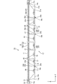
続いて、バックライト装置12について説明する。バックライト装置12は、図2に示すように、光出射部側(液晶パネル11側)に光源からの光を出射させる開口部14bを有した略箱型をなすシャーシ14と、シャーシ14の開口部14bを覆うようにして配される光学部材15群(拡散板15aと、拡散板15aと液晶パネル11との間に配される複数の光学シート15b)、シャーシ14の外縁部に沿って配され光学部材15群の外縁部をシャーシ14との間で挟んで保持するフレーム16とを備える。さらに、シャーシ14内には、図3から図5に示すように、光源であるLED17(Light Emitting Diode:発光ダイオード)と、LED17が実装されたLED基板18(光源基板)と、LED基板18においてLED17を個別に覆うように取り付けられる拡散レンズ40(光学素子)とが備えられる。その上、シャーシ14内には、LED基板18をシャーシ14に対して固定するリベット20と、シャーシ14内の光を光学部材15側に反射させる反射シート21と、反射シート20をシャーシ14と反対側から保持する反射シート保持部材30とが備えられる。以下では、バックライト装置12の各構成部品について説明する。
Subsequently, the backlight device 12 will be described. As shown in FIG. 2, the backlight device 12 includes a substantially box-shaped chassis 14 having an opening 14 b that emits light from a light source on the light emitting part side (liquid crystal panel 11 side), and an opening of the chassis 14. The optical member 15 group (the diffuser plate 15 a and the plurality of optical sheets 15 b disposed between the diffuser plate 15 a and the liquid crystal panel 11) arranged so as to cover the portion 14 b, and arranged along the outer edge of the chassis 14. And a frame 16 for holding the outer edge of the optical member 15 group between the chassis 14 and the frame 16. Further, in the chassis 14, as shown in FIGS. 3 to 5, an LED 17 (Light Emitting で Diode) as a light source, an LED substrate 18 (light source substrate) on which the LED 17 is mounted, and an LED substrate 18 And a diffusing lens 40 (optical element) attached to individually cover the LEDs 17. In addition, in the chassis 14, a rivet 20 that fixes the LED board 18 to the chassis 14, a reflection sheet 21 that reflects light in the chassis 14 toward the optical member 15, and the reflection sheet 20 opposite to the chassis 14. A reflection sheet holding member 30 that is held from the side is provided. Below, each component of the backlight apparatus 12 is demonstrated.
シャーシ14は、金属製とされ、図3から図5に示すように、液晶パネル11と同様に矩形状をなす底板14aと、底板14aの各辺の外端から立ち上がる側板14cと、各側板14cの立ち上がり端から外向きに張り出す受け板14dとからなり、全体としては表側に向けて開口した浅い略箱型(略浅皿状)をなしている。シャーシ14は、その長辺方向がX軸方向と一致し、短辺方向がY軸方向と一致している。シャーシ14における各受け板14dには、表側からフレーム16及び次述する光学部材15が載置可能とされる。なお、フレーム16は受け板14dに対してねじ止めされている。また、シャーシ14の底板14aには、保持部材20を取り付けるための取付孔が開口して設けられている。
The chassis 14 is made of metal and, as shown in FIGS. 3 to 5, has a rectangular bottom plate 14a similar to the liquid crystal panel 11, a side plate 14c rising from an outer end of each side of the bottom plate 14a, and each side plate 14c. And a receiving plate 14d projecting outward from the rising edge, and as a whole, has a shallow substantially box shape (substantially shallow dish shape) opened toward the front side. The long side direction of the chassis 14 matches the X-axis direction, and the short side direction matches the Y-axis direction. A frame 16 and an optical member 15 to be described below can be placed on each receiving plate 14d in the chassis 14 from the front side. The frame 16 is screwed to the receiving plate 14d. In addition, an attachment hole for attaching the holding member 20 is provided in the bottom plate 14a of the chassis 14 so as to open.
光学部材15は、図2に示すように、液晶パネル11及びシャーシ14と同様に平面に視て横長の方形(矩形状)をなしている。光学部材15は、図4及び図5に示すように、その外縁部が受け板14dに載せられることで、シャーシ14の開口部14bを覆うとともに、液晶パネル11とLED17との間に介在して配される。光学部材15は、裏側(LED17側、光出射部12a側とは反対側)に配される拡散板15aと、表側(液晶パネル11側、光出射部12a側)に配される光学シート15bとから構成される。拡散板15aは、所定の厚みを持つほぼ透明な樹脂製の基材内に拡散粒子を多数分散して設けた構成とされ、透過する光を拡散させる機能を有する。光学シート15bは、拡散板15aと比べると板厚が薄いシート状をなしており、2枚が積層して配されている。具体的な光学シート15bの種類としては、例えば拡散シート、レンズシート、反射型偏光シートなどがあり、これらの中から適宜に選択して使用することが可能である。
As shown in FIG. 2, the optical member 15 has a horizontally long rectangular shape (rectangular shape) in a plan view, like the liquid crystal panel 11 and the chassis 14. As shown in FIGS. 4 and 5, the optical member 15 has its outer edge portion placed on the receiving plate 14 d so as to cover the opening 14 b of the chassis 14 and be interposed between the liquid crystal panel 11 and the LED 17. Arranged. The optical member 15 includes a diffusion plate 15a disposed on the back side (the side opposite to the LED 17 side and the light emitting unit 12a side), and an optical sheet 15b disposed on the front side (the liquid crystal panel 11 side and the light emitting unit 12a side). Consists of The diffusing plate 15a has a structure in which a large number of diffusing particles are dispersed in a substantially transparent resin base material having a predetermined thickness, and has a function of diffusing transmitted light. The optical sheet 15b has a sheet shape that is thinner than the diffusion plate 15a, and two optical sheets 15b are laminated. Specific types of the optical sheet 15b include, for example, a diffusion sheet, a lens sheet, a reflective polarizing sheet, and the like, which can be appropriately selected and used.
フレーム16は、図2に示すように、液晶パネル11及び光学部材15の外周縁部に沿う枠状をなしている。このフレーム16と各受け板14dとの間で光学部材15における外縁部を挟持可能とされている(図4及び図5)。また、このフレーム16は、液晶パネル11における外縁部を裏側から受けることができ、表側に配されるベゼル13との間で液晶パネル11の外縁部を挟持可能とされる(図4及び図5)。
As shown in FIG. 2, the frame 16 has a frame shape along the outer peripheral edge portions of the liquid crystal panel 11 and the optical member 15. An outer edge portion of the optical member 15 can be sandwiched between the frame 16 and each receiving plate 14d (FIGS. 4 and 5). The frame 16 can receive the outer edge portion of the liquid crystal panel 11 from the back side, and can sandwich the outer edge portion of the liquid crystal panel 11 with the bezel 13 disposed on the front side (FIGS. 4 and 5). ).
次に、LED17及びLED17が実装されるLED基板18について説明する。LED17は、LED基板18に固着される基板部上にLEDチップを樹脂材により封止した構成とされる。基板部に実装されるLEDチップは、主発光波長が1種類とされ、具体的には、青色を単色発光するものが用いられている。その一方、LEDチップを封止する樹脂材には、LEDチップから発せられた青色の光を、白色の光に変換する蛍光体が分散配合されている。これにより、このLED17は、白色発光が可能とされる。このLED17は、LED基板18に対する実装面とは反対側の面が発光面となる、いわゆるトップ型とされている。LED17における光軸LAは、Z軸方向(液晶パネル11及び光学部材15の主板面と直交する方向)とほぼ一致する設定とされている。なお、LED17から発せられる光は、光軸LAを中心にして所定の角度範囲内で三次元的にある程度放射状に広がるのであるが、その指向性は冷陰極管などと比べると高くなっている。つまり、LED17の発光強度は、光軸LAに沿った方向が高く、光軸LAに対する傾き角度が大きくなるに連れて低下するような傾向の角度分布を示す。
Next, the LED 17 and the LED board 18 on which the LED 17 is mounted will be described. The LED 17 has a configuration in which an LED chip is sealed with a resin material on a substrate portion fixed to the LED substrate 18. The LED chip mounted on the substrate unit has one main emission wavelength, and specifically, one that emits blue light in a single color is used. On the other hand, a phosphor that converts blue light emitted from the LED chip into white light is dispersed and blended in the resin material for sealing the LED chip. As a result, the LED 17 can emit white light. The LED 17 is a so-called top type in which a surface opposite to the mounting surface with respect to the LED substrate 18 is a light emitting surface. The optical axis LA of the LED 17 is set to substantially coincide with the Z-axis direction (direction orthogonal to the main plate surfaces of the liquid crystal panel 11 and the optical member 15). Note that the light emitted from the LED 17 spreads radially to some extent within a predetermined angle range around the optical axis LA, but its directivity is higher than that of a cold cathode tube or the like. That is, the emission intensity of the LED 17 shows an angular distribution that tends to decrease as the direction along the optical axis LA is high and the tilt angle with respect to the optical axis LA increases.
LED基板18は、平面に視て矩形状(短冊状)をなし、長辺方向がX軸方向(シャーシ14の底板14aの長辺方向)と一致し、短辺方向がY軸方向(シャーシ14の底板14aの短辺方向)と一致する状態でシャーシ14内において底板14aに沿って延在しつつ収容されている(図3~図5)。LED基板18の基材は、シャーシ14と同じアルミ系材料などの金属製とされ、その表面に図示しない絶縁層を介して銅箔などの金属膜からなる配線パターン(不図示)が形成された構成とされる。そして、このLED基板18の板面のうち、表側を向いた面(光学部材15側を向いた面)には、図9に示すように、上記した構成のLED17が表面実装されている。LED17は、LED基板18における長辺方向(X軸方向)に沿って複数が直線的に並列して配されるとともに、LED基板18に形成された配線パターンにより直列接続されている。各LED17の配列ピッチは、ほぼ一定となっており、つまり各LED17は、等間隔に配列されている。また、LED基板18における長辺方向の両端部には、コネクタ部18aが設けられている。
The LED substrate 18 has a rectangular shape (strip shape) when viewed in plan, the long side direction coincides with the X-axis direction (long side direction of the bottom plate 14a of the chassis 14), and the short side direction corresponds to the Y-axis direction (chassis 14). And extends along the bottom plate 14a in the chassis 14 so as to coincide with the bottom plate 14a (in the short side direction) (FIGS. 3 to 5). The base material of the LED substrate 18 is made of the same metal as the chassis 14 such as an aluminum material, and a wiring pattern (not shown) made of a metal film such as a copper foil is formed on the surface of the substrate via an insulating layer (not shown). It is supposed to be configured. Of the plate surfaces of the LED substrate 18, the surface of the LED 17 having the above-described configuration is mounted on the surface facing the front side (the surface facing the optical member 15 side) as shown in FIG. 9. A plurality of LEDs 17 are linearly arranged in parallel along the long side direction (X-axis direction) of the LED substrate 18, and are connected in series by a wiring pattern formed on the LED substrate 18. The arrangement pitch of the LEDs 17 is substantially constant, that is, the LEDs 17 are arranged at equal intervals. Moreover, the connector part 18a is provided in the both ends of the long side direction in the LED board 18. As shown in FIG.
上記した構成のLED基板18は、図3に示すように、シャーシ14内においてX軸方向及びY軸方向にそれぞれ複数ずつ、互いに長辺方向及び短辺方向を揃えた状態で並列して配置されている。つまり、LED基板18及びそこに実装されたLED17は、シャーシ14内において共にX軸方向(シャーシ14及びLED基板18の長辺方向)を行方向とし、Y軸方向(シャーシ14及びLED基板18の短辺方向)を列方向として行列配置(マトリクス状に配置)されている。具体的には、LED基板18は、シャーシ14内においてX軸方向に3枚ずつ、Y軸方向に9枚ずつ、合計27枚が並列して配置されている。そして、本実施形態では、LED基板18として長辺寸法及び実装されるLED17の数が異なる2種類のものが用られている。具体的には、LED基板18としては、6個のLED17が実装され、長辺寸法が相対的に長い6個実装タイプのものと、5個のLED17が実装され、長辺寸法が相対的に短い5個実装タイプのものとが用いられており、シャーシ14におけるX軸方向の両端位置に6個実装タイプのものが1枚ずつ、同方向の中央位置に5個実装タイプのものが1枚、それぞれ配されている。上記したようにX軸方向に沿って並んで1つの行をなす各LED基板18は、隣接するコネクタ部18a同士が嵌合接続されることで相互に電気的に接続されるとともに、シャーシ14におけるX軸方向の両端に対応したコネクタ部18aが図示しない外部の制御回路に対してそれぞれ電気的に接続される。これにより、1つの行をなす各LED基板18に配された各LED17が直列接続されるとともに、その1つの行に含まれる多数のLED17の点灯・消灯を1つの制御回路により一括して制御することができる。なお、長辺寸法及び実装されるLED17の数が異なる種類のLED基板18であっても、短辺寸法及びLED17の配列ピッチは、ほぼ同じとされる。
As shown in FIG. 3, the LED substrate 18 having the above-described configuration is arranged in parallel in the chassis 14 in a state where the long side direction and the short side direction are aligned with each other in the X-axis direction and the Y-axis direction. ing. That is, the LED board 18 and the LED 17 mounted thereon are both set in the X-axis direction (the long side direction of the chassis 14 and the LED board 18) in the chassis 14 and in the Y-axis direction (of the chassis 14 and the LED board 18). Matrix arrangement (arranged in a matrix) with the short side direction as the column direction. Specifically, a total of 27 LED substrates 18 are arranged in parallel in the chassis 14, three in the X-axis direction and nine in the Y-axis direction. In the present embodiment, two types of LED substrates 18 having different long side dimensions and the number of mounted LEDs 17 are used. Specifically, as the LED substrate 18, six LEDs 17 are mounted, and the long side dimension is a relatively long six-part mounting type and the five LEDs 17 are mounted, and the long side dimension is relatively long. The short five-mount type is used, one for the six-mount type at the X-axis direction end position of the chassis 14 and one for the five-mount type at the central position in the same direction. , Each is arranged. As described above, the LED boards 18 that form one row along the X-axis direction are electrically connected to each other by fitting and connecting the adjacent connector portions 18a to each other. Connector portions 18a corresponding to both ends in the X-axis direction are electrically connected to external control circuits (not shown). As a result, the LEDs 17 arranged on the LED boards 18 in one row are connected in series, and the lighting / extinction of a large number of LEDs 17 included in the row is collectively controlled by a single control circuit. be able to. In addition, even if it is a kind of LED board 18 from which the long side dimension and the number of LED17 mounted differ, the short side dimension and the arrangement pitch of LED17 are made substantially the same.
このように、長辺寸法及び実装されるLED17の数が異なるLED基板18を複数種類用意し、それら異なる種類のLED基板18を適宜に組み合わせて使用する手法を採用することで、次の効果を得ることができる。すなわち、画面サイズが異なる液晶表示装置10を多品種製造する場合、各画面サイズに合わせて各種類のLED基板18の使用の是非及び種類毎のLED基板18の使用枚数を適宜変更することで容易に対応することができる。このため、仮にシャーシ14の長辺寸法と同等の長辺寸法を有する専用設計のLED基板を画面サイズ毎に用意した場合と比べると、必要なLED基板18の種類を大幅に削減することができ、もって製造コストの低廉化を図ることができる。
In this way, by preparing a plurality of types of LED substrates 18 having different long side dimensions and the number of LEDs 17 to be mounted, and employing a method of appropriately combining and using these different types of LED substrates 18, the following effects can be obtained. Obtainable. That is, when manufacturing various types of liquid crystal display devices 10 having different screen sizes, it is easy to change the appropriateness of the use of each type of LED board 18 and the number of LED boards 18 used for each type according to each screen size. It can correspond to. For this reason, compared with the case where the LED board of the special design which has a long side dimension equivalent to the long side dimension of the chassis 14 is prepared for every screen size, the kind of required LED board 18 can be reduced significantly. Therefore, the manufacturing cost can be reduced.
拡散レンズ40は、ほぼ透明で(高い透光性を有し)且つ屈折率が空気よりも高い合成樹脂材料(例えばポリカーボネートやアクリルなど)からなる。拡散レンズ40は、図9に示すように、LED基板18に対する拡散レンズ40の取付構造となる取付脚部41と、取付脚部41に支持されるとともに、当該取付脚部41から庇状に延びるレンズ部42とで構成されている。拡散レンズ40は、図3に示すように、LED基板18に対して各LED17を表側から個別に覆うよう、つまり平面に視て各LED17と重畳するようそれぞれ取り付けられている。すなわち、拡散レンズ40は、LED基板18をシャーシ14の底板14aに取り付けた状態では、LED17と同様に9行17列に行列配置されている。そして、この拡散レンズ40は、LED17から発せられた指向性の強い光を拡散させつつ出射させることができる。これにより、LED17の設置個数を少なくすることが可能となっている。拡散レンズ40は、X軸方向及びY軸方向の寸法が共にLED17よりも十分に大きいものとされる。一方、拡散レンズ40は、X軸方向およびY軸方向の寸法がLED基板18より小さいものとされる。従って、Z軸方向において、拡散レンズ40と重なる領域には、LED基板18が配されることになる。
The diffusing lens 40 is made of a synthetic resin material (for example, polycarbonate, acrylic, etc.) that is substantially transparent (having high translucency) and has a higher refractive index than air. As shown in FIG. 9, the diffusing lens 40 is supported by the mounting leg 41 serving as a mounting structure of the diffusing lens 40 with respect to the LED substrate 18 and the mounting leg 41, and extends from the mounting leg 41 in a bowl shape. It is comprised with the lens part 42. FIG. As shown in FIG. 3, the diffusing lens 40 is attached to the LED substrate 18 so as to individually cover the LEDs 17 from the front side, that is, to overlap the LEDs 17 when viewed in a plane. That is, the diffusion lenses 40 are arranged in a matrix of 9 rows and 17 columns in the same manner as the LEDs 17 when the LED substrate 18 is attached to the bottom plate 14 a of the chassis 14. The diffusing lens 40 can emit light having a strong directivity emitted from the LED 17 while diffusing. Thereby, it is possible to reduce the number of installed LEDs 17. The diffuser lens 40 is sufficiently larger in both the X-axis direction and the Y-axis direction than the LED 17. On the other hand, the diffuser lens 40 is smaller in the X-axis direction and the Y-axis direction than the LED substrate 18. Accordingly, the LED substrate 18 is disposed in a region overlapping the diffusing lens 40 in the Z-axis direction.
取付脚部41は、円柱状をなし、レンズ部42からLED基板18側に向けて突設されている。取付脚部41は、図8に示すように、レンズ部42のうち、後述する光入射側凹部42cよりも外周端部に近い位置に3つ配されており、各取付脚部41を結んだ線が平面に視てほぼ正三角形をなす位置に配されている。各取付脚部41は、その先端部が接着剤などによりLED基板18に固着される。拡散レンズ40は、LED基板18に取り付けられた状態では、その3つの取付脚部41がLED17を取り囲む位置に配されている。そして、1枚のLED基板18に固着される各拡散レンズ40は、互いの向きを揃えて配されている。具体的には、その3つの取付脚部41のうち、1つの取付脚部41がLED基板18の短手方向の中央部に配されるとともに、他の2つの取付脚部41が短手方向の中央部を通る線を軸にして、線対称をなして配されている。
The mounting leg portion 41 has a cylindrical shape, and protrudes from the lens portion 42 toward the LED substrate 18 side. As shown in FIG. 8, three attachment legs 41 are arranged in the lens part 42 at positions closer to the outer peripheral end than a light incident side recess 42 c described later, and connect the attachment legs 41. The line is arranged at a position that forms a substantially equilateral triangle when seen in a plane. Each mounting leg 41 is fixed to the LED substrate 18 at its tip by an adhesive or the like. In the state where the diffusing lens 40 is attached to the LED substrate 18, the three attachment legs 41 are arranged at positions where the LEDs 17 are surrounded. And each diffuser lens 40 fixed to one LED board 18 is arranged with the direction of each other aligned. Specifically, of the three mounting legs 41, one mounting leg 41 is disposed at the center of the LED board 18 in the short direction, and the other two mounting legs 41 are in the short direction. It is arranged in line symmetry with the line passing through the center of the axis as the axis.
レンズ部42は、平面に視て略円形状をなし、LED17とほぼ同心となる位置に配されている。レンズ部42は、LED基板18と対向する面がLED17からの光が入射される光入射面41aとされるのに対し、光学部材15と対向する面が光を出射する光出射面42bとされる。レンズ部42は、取付脚部41を介してLED基板18に固定されることで、その光入射面42aとLED基板18との間に所定の隙間が空けられるようになっている。光入射面42aは、図9に示すように、全体としてはLED基板18の板面に沿って並行する形態とされるものの、平面に視てLED17と重畳する領域に光入射側凹部42cが形成されることで傾斜面を有している。光入射側凹部42cは、略円錐状をなすとともに拡散レンズ40においてほぼ同心位置に配されており、裏側、つまりLED17側に向けて開口する形態とされる。光入射側凹部42cは、断面が略逆V字型をなしており、その周面がZ軸方向に対して傾いた傾斜面とされる。従って、LED17から発せられて光入射側凹部42c内に入った光は、傾斜面を介して拡散レンズ40内に入射するのであるが、そのとき光軸LAに対する傾斜面の傾斜角度の分だけ、中心から遠ざかる方向、つまり広角に屈折されて拡散レンズ40に入射する。
The lens part 42 has a substantially circular shape when seen in a plan view, and is arranged at a position that is substantially concentric with the LED 17. In the lens unit 42, the surface facing the LED substrate 18 is a light incident surface 41 a on which light from the LED 17 is incident, whereas the surface facing the optical member 15 is a light emitting surface 42 b that emits light. The The lens portion 42 is fixed to the LED substrate 18 via the mounting leg portion 41 so that a predetermined gap is formed between the light incident surface 42 a and the LED substrate 18. As shown in FIG. 9, the light incident surface 42 a is formed in parallel with the plate surface of the LED substrate 18 as a whole, but a light incident side recess 42 c is formed in a region overlapping the LED 17 when seen in a plan view. It has an inclined surface. The light incident side concave portion 42c has a substantially conical shape and is disposed at a substantially concentric position in the diffusing lens 40, and is open toward the back side, that is, the LED 17 side. The light incident side recess 42c has a substantially inverted V-shaped cross section, and its peripheral surface is inclined with respect to the Z-axis direction. Therefore, the light emitted from the LED 17 and entering the light incident side recess 42c enters the diffusion lens 40 through the inclined surface, but at that time, the amount of the inclination angle of the inclined surface with respect to the optical axis LA is as follows. The light is refracted in a direction away from the center, that is, a wide angle, and enters the diffusing lens 40.
レンズ部42の光出射面42bは、扁平な略球面状に形成されている。これにより、拡散レンズ40から出射する光を、外部の空気層との界面にて中心から遠ざかる方向、つまり広角に屈折させつつ出射させることが可能となる。この光出射面42bのうち平面に視てLED17と重畳する領域には、光出射側凹部42dが形成されている。光出射側凹部42dは、略擂鉢状をなすとともに、その周面が中心に向かって下り勾配となる扁平な略球面状に形成されている。また、光出射側凹部42dにおける周面の接線がLED17の光軸LAに対してなす角度は、光入射側凹部42cの傾斜面が光軸LAに対してなす角度よりも相対的に大きくなるものとされる。光出射面42bのうち平面に視てLED17と重畳する領域に光出射側凹部42dを形成することにより、LED17からの光の多くを広角に屈折させつつ出射させたり、或いはLED17からの光の一部をLED基板18側に反射させることができる。
The light exit surface 42b of the lens part 42 is formed in a flat and substantially spherical shape. As a result, the light emitted from the diffusing lens 40 can be emitted while being refracted in a direction away from the center at the interface with the external air layer, that is, a wide angle. A light exit side recess 42d is formed in a region of the light exit surface 42b that overlaps the LED 17 when viewed in plan. The light emitting side concave portion 42d has a substantially bowl shape, and is formed in a flat and substantially spherical shape with a peripheral surface having a downward slope toward the center. The angle formed by the tangent to the peripheral surface of the light exit side recess 42d with respect to the optical axis LA of the LED 17 is relatively larger than the angle formed by the inclined surface of the light incident side recess 42c with respect to the optical axis LA. It is said. By forming a light exit side recess 42d in a region of the light exit surface 42b that overlaps the LED 17 when viewed in plan, much of the light from the LED 17 is refracted at a wide angle or emitted from the LED 17 The portion can be reflected to the LED substrate 18 side.
反射シート21は、合成樹脂製とされ、表面が光の反射性に優れた白色を呈するものとされる。反射シート21は、図3に示すように、シャーシ14の内面のほぼ全域にわたって敷設される大きさを有しているので、シャーシ14内に並列して配された全LED基板18を表側から一括して覆うことが可能とされる。この反射シート21によりシャーシ14内の光を光学部材15側に向けて効率的に立ち上げることができる。反射シート21は、シャーシ14の底板14aに沿って延在するとともに底板14aの大部分を覆う大きさの底部21aと、底部21aの各外端から表側に立ち上がるとともに底部21aに対して傾斜状をなす4つの立ち上がり部21bと、各立ち上がり部21bの外端から外向きに延出するとともにシャーシ14の受け板14dに載せられる延出部21cとから構成されている。この反射シート21の底部21aが各LED基板18におけるLED17が実装された板面に対して表側に重なるよう配される。また、反射シート21の底部21aには、各拡散レンズ40(各LED17)と平面視重畳する位置に、各LED17を露出するとともに、各拡散レンズ40を挿通するレンズ挿通孔21d(開口部)が設けられている。レンズ挿通孔21dは、図8に示すように、平面に視て円形状をなしており、その径寸法は拡散レンズ40よりも大きくなる設定とされる。これにより、反射シート21をシャーシ14内に敷設する際、寸法誤差の有無に拘わらず各拡散レンズ40を各レンズ挿通孔21dに対して確実に通すことができる。さらに、反射シート21の底部21aには、各コネクタ部18aと平面視重畳する位置に、各コネクタ部18aを挿通するコネクタ挿通孔21eが設けられている。
The reflection sheet 21 is made of a synthetic resin, and the surface of the reflection sheet 21 is white with excellent light reflectivity. As shown in FIG. 3, the reflection sheet 21 has a size that is laid over almost the entire inner surface of the chassis 14, so that all the LED boards 18 that are arranged in parallel in the chassis 14 are collectively displayed from the front side. And can be covered. The reflection sheet 21 can efficiently raise the light in the chassis 14 toward the optical member 15 side. The reflection sheet 21 extends along the bottom plate 14a of the chassis 14 and covers a large portion of the bottom plate 14a. The reflection sheet 21 rises from each outer end of the bottom portion 21a to the front side and is inclined with respect to the bottom portion 21a. The four rising portions 21b and the extending portions 21c that extend outward from the outer ends of the respective rising portions 21b and are placed on the receiving plate 14d of the chassis 14 are configured. The bottom portion 21a of the reflection sheet 21 is disposed so as to overlap the front side with respect to the plate surface on which the LEDs 17 of each LED board 18 are mounted. In addition, the bottom portion 21a of the reflection sheet 21 has a lens insertion hole 21d (opening portion) through which each LED 17 is exposed and at which the respective diffusion lenses 40 are inserted at a position overlapping each diffusion lens 40 (each LED 17) in plan view. Is provided. As shown in FIG. 8, the lens insertion hole 21 d has a circular shape when seen in a plan view, and the diameter thereof is set to be larger than that of the diffusing lens 40. Thus, when the reflecting sheet 21 is laid in the chassis 14, each diffusing lens 40 can be surely passed through each lens insertion hole 21d regardless of the presence or absence of a dimensional error. Further, the bottom portion 21a of the reflection sheet 21 is provided with a connector insertion hole 21e through which each connector portion 18a is inserted at a position overlapping with each connector portion 18a in plan view.
リベット20は、図4および図5に示すように、円盤状の押え部20dと、当該押え部20dから下方側へ突出する係止部20eとを有する。LED基板18には、係止部20eを挿通するための貫通孔18bが穿設されており、またシャーシ14の底板14aには、当該貫通孔18bと連通する取付孔(不図示)が穿設されている。リベット20の係止部20eの先端部は弾性変形可能な幅広部となっており、貫通孔18b及び取付孔に挿通された後、シャーシ14の底板14aの裏面側に係止可能となっている。これにより、リベット20は、押え部20dでLED基板20を押えつつ、当該LED基板20を底板14aに固定可能となっている。このリベット20は、図3に示すように、LED基板18の面内において複数が適宜に分散配置されており、X軸方向について拡散レンズ40(LED17)に対して隣り合う位置に配されている。なお、図3に示すように、LED基板18には、隣り合う拡散レンズ40の間にリベット20が配されない箇所が存在するが、当該箇所においては、LED基板18の配線パターンの配線幅を十分に確保するために、貫通孔18bが設けられていない。
As shown in FIGS. 4 and 5, the rivet 20 has a disc-shaped presser portion 20d and a locking portion 20e protruding downward from the presser portion 20d. The LED board 18 is provided with a through hole 18b for inserting the locking portion 20e, and the bottom plate 14a of the chassis 14 is provided with a mounting hole (not shown) communicating with the through hole 18b. Has been. The front end of the locking portion 20e of the rivet 20 is a wide portion that can be elastically deformed, and can be locked to the back side of the bottom plate 14a of the chassis 14 after being inserted into the through hole 18b and the mounting hole. . Thereby, the rivet 20 can fix the LED substrate 20 to the bottom plate 14a while pressing the LED substrate 20 with the holding portion 20d. As shown in FIG. 3, a plurality of the rivets 20 are appropriately distributed in the plane of the LED substrate 18, and are arranged at positions adjacent to the diffusion lens 40 (LED 17) in the X-axis direction. . As shown in FIG. 3, the LED substrate 18 has a portion where the rivet 20 is not disposed between the adjacent diffuser lenses 40, but the wiring width of the wiring pattern of the LED substrate 18 is sufficient in the portion. In order to ensure, the through-hole 18b is not provided.
リベット20のうち、図4および図5に示すように、シャーシ14の底板14aの中央部付近に位置するリベット20Bの表面には、支持ピン27が突設されている。支持ピン27は、先細りする円錐形とされており、拡散板15aが下方側へ撓んだ際に、当該拡散板15aと支持ピン27の先端とが点接触することにより、拡散板15aを下方から支持することが可能となっている。
As shown in FIGS. 4 and 5, a support pin 27 protrudes from the surface of the rivet 20 </ b> B located near the center of the bottom plate 14 a of the chassis 14. The support pin 27 has a tapered conical shape. When the diffusion plate 15a is bent downward, the diffusion plate 15a and the tip of the support pin 27 come into point contact so that the diffusion plate 15a is moved downward. It is possible to support from.
ここで、反射シート21には、リベット20の係止部20eを挿通するための挿通孔(不図示)が設けられている。反射シート21に設けられた当該挿通孔の径は、押え部20dの径より小さいものとされている。すなわち、反射シート21は、当該挿通孔の孔縁において、LED基板18とともに押え部20dとシャーシ14とに挟持され、リベット20によりシャーシ14に対して保持されるものとされている。
Here, the reflection sheet 21 is provided with an insertion hole (not shown) through which the locking portion 20e of the rivet 20 is inserted. The diameter of the insertion hole provided in the reflection sheet 21 is smaller than the diameter of the pressing portion 20d. That is, the reflection sheet 21 is sandwiched between the pressing portion 20 d and the chassis 14 together with the LED substrate 18 at the hole edge of the insertion hole, and is held by the rivet 20 with respect to the chassis 14.
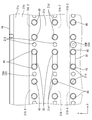
反射シート保持部材30について詳しく説明する。反射シート保持部材30は、図8および図9に示すように、反射性に優れた、弾性を有する、環状部材とされている。言い換えれば、反射シート保持部材30は、白色をなす、輪ゴム状の部材とされている。反射シート保持部材30の全周の長さは、弾性伸長しない状態で、シャーシ内においてX軸方向に隣り合う拡散レンズ40,40の6つの取付脚部41のうち、外側に配される5つの取付脚部41の外面を結ぶ長さより短いものとされている。言い換えれば、平面視にて、当該5つの取付脚部41の配置部を頂点とする五角形状の周の長さより短いものとされている。そして、反射シート保持部材30は、その幅寸法Wが、反射シート21のシート面と、当該シート面に対向するレンズ部42の庇状部分をなす光入射面42aとの離間距離Lと略同じ寸法とされている。
The reflective sheet holding member 30 will be described in detail. As shown in FIGS. 8 and 9, the reflection sheet holding member 30 is an annular member having excellent reflectivity and elasticity. In other words, the reflection sheet holding member 30 is a rubber band-shaped member that is white. The length of the entire circumference of the reflection sheet holding member 30 is five, which is arranged on the outer side among the six mounting legs 41 of the diffusion lenses 40 and 40 adjacent to each other in the X-axis direction in the chassis without being elastically extended. The length is shorter than the length connecting the outer surfaces of the mounting legs 41. In other words, in plan view, it is shorter than the circumference of the pentagonal shape with the arrangement portion of the five mounting leg portions 41 as the apex. The width W of the reflection sheet holding member 30 is substantially the same as the separation distance L between the sheet surface of the reflection sheet 21 and the light incident surface 42a that forms the bowl-shaped portion of the lens portion 42 facing the sheet surface. It is a dimension.
反射シート保持部材30は、図8および図9に示すように、シャーシ14内において、X軸方向に隣り合う拡散レンズ40,40に係止されている。詳しくは、反射シート保持部材30は、周の長さが伸長され、拡散レンズ40,40を取り囲むように配されるとともに、周方向に収縮しようとする弾発力により取付脚部41に係止されている。このとき、反射シート保持部材30は、上述の5つの取付脚部41の配置形状に倣い、平面視五角形状をなす。そして、反射シート保持部材30は、幅方向(Z軸方向)においては、レンズ部42の庇状に張り出した部分に係止されている。さらに、反射シート保持部材30は、拡散レンズ40と重畳する部分においては、レンズ部42の光入射面42aと密着するとともに、隣り合うレンズ挿通孔21dの間においては、反射シート21の上側(シャーシ14と反対側)のシート面に密着するものとされている。すなわち、反射シート保持部材30は、レンズ挿通孔21dの孔縁をレンズ部42側(シャーシ14と反対側)から押える構成とされている。
As shown in FIGS. 8 and 9, the reflection sheet holding member 30 is locked to the diffusion lenses 40, 40 adjacent in the X-axis direction in the chassis 14. Specifically, the reflection sheet holding member 30 has a circumferential length that is extended so as to surround the diffusing lenses 40 and 40, and is locked to the mounting leg 41 by a resilient force that tends to contract in the circumferential direction. Has been. At this time, the reflection sheet holding member 30 has a pentagonal shape in plan view, following the arrangement shape of the five mounting legs 41 described above. Then, the reflection sheet holding member 30 is locked to a portion of the lens portion 42 that protrudes like a bowl in the width direction (Z-axis direction). Further, the reflection sheet holding member 30 is in close contact with the light incident surface 42a of the lens portion 42 at a portion overlapping with the diffusing lens 40, and between the adjacent lens insertion holes 21d (on the chassis). 14) and the sheet surface on the opposite side. That is, the reflection sheet holding member 30 is configured to press the hole edge of the lens insertion hole 21d from the lens portion 42 side (the side opposite to the chassis 14).
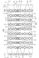
次に、反射シート保持部材30のシャーシ14内における配置構成について説明する。まず、反射シート保持部材30は、9行17列に行列配置された拡散レンズ40のうち、行方向(X軸方向)の端部に位置する、すなわち1列目と17列目に位置する拡散レンズ40Eとこれに隣接する拡散レンズ40に係止されている。また、当該拡散レンズ40,40間にリベット20が配されていない、3列目と4列目に位置する拡散レンズ40,40と、14列目と15列目に位置する拡散レンズ40,40とにそれぞれ係止されている。さらに、当該拡散レンズ40,40間にコネクタ部18aが配されている、6列目と7列目に位置する拡散レンズ40,40と、11列目と12列目に位置する拡散レンズ40,40とにそれぞれ係止されている。
Next, the arrangement configuration of the reflection sheet holding member 30 in the chassis 14 will be described. First, the reflection sheet holding member 30 is located at the end in the row direction (X-axis direction) of the diffusion lenses 40 arranged in a matrix of 9 rows and 17 columns, that is, the diffusions located in the first column and the 17th column. The lens 40E and the diffusing lens 40 adjacent thereto are locked. Further, the rivets 20 are not arranged between the diffusion lenses 40 and 40, the diffusion lenses 40 and 40 located in the third row and the fourth row, and the diffusion lenses 40 and 40 located in the 14th row and the 15th row. And are respectively locked. Further, the connector portion 18a is disposed between the diffusion lenses 40, 40, the diffusion lenses 40, 40 located in the sixth row and the seventh row, and the diffusion lenses 40, located in the eleventh row and the twelfth row. 40 are respectively locked.
図6に示すように、1列目と2列目に位置する拡散レンズ40E,40に係止される反射シート保持部材30は、1列目に位置する拡散レンズ40Eを挿通する反射シート挿通孔21dの孔縁を、2箇所においてシャーシ14の底板側に押えるものとされている。ここで、1列目と2列目に位置する拡散レンズ40E,40の間には、リベット20Aが配されているが、反射シート保持部材30は、当該リベット20Aより反射シート21の端部側において、反射シート21をシャーシ14に対して保持する配置構成とされている。なお、当該リベット20Aは、環状をなす反射シート保持部材30の周内に配されており、リベット20Aと反射シート保持部材30とが干渉することはない。16列目と17列目に位置する拡散レンズ40,40Eに係止される反射シート保持部材30は、1列目と2列目に位置する拡散レンズ40E,40に係止される反射シート保持部材30と左右対称の配置構成であるため、説明を省略する。
As shown in FIG. 6, the reflection sheet holding member 30 locked to the diffusion lenses 40 </ b> E and 40 located in the first row and the second row has a reflection sheet insertion hole through which the diffusion lens 40 </ b> E located in the first row is inserted. The hole edge of 21d is pressed against the bottom plate side of the chassis 14 at two locations. Here, a rivet 20A is arranged between the diffusing lenses 40E and 40 located in the first row and the second row, but the reflecting sheet holding member 30 is located on the end side of the reflecting sheet 21 from the rivet 20A. In FIG. 2, the reflection sheet 21 is held with respect to the chassis 14. The rivet 20A is disposed in the circumference of the annular reflection sheet holding member 30, and the rivet 20A and the reflection sheet holding member 30 do not interfere with each other. The reflection sheet holding member 30 locked to the diffusion lenses 40 and 40E positioned in the 16th and 17th rows is the reflection sheet holding member locked to the diffusion lenses 40E and 40 positioned in the first and second rows. Since the configuration is symmetrical with the member 30, the description is omitted.
また、図6に示すように、3列目と4列目に位置する拡散レンズ40,40に係止される反射シート保持部材30は、リベット20により保持されない、3列目と4列目に位置する拡散レンズ40,40をそれぞれ挿通するレンズ挿通孔21d,21dの間をシャーシ14に対して保持する構成とされている。14列目と15列目に位置する拡散レンズ40,40に係止される反射シート保持部材30は、3列目と4列目に位置する拡散レンズ40,40に係止される反射シート保持部材30と同様の配置構成であるため、説明を省略する。
Further, as shown in FIG. 6, the reflection sheet holding members 30 locked to the diffusion lenses 40, 40 located in the third row and the fourth row are not held by the rivet 20 in the third row and the fourth row. The configuration is such that the space between the lens insertion holes 21d and 21d through which the diffused lenses 40 and 40 are positioned is held with respect to the chassis 14. The reflection sheet holding member 30 locked to the diffusion lenses 40 and 40 located in the 14th and 15th rows is the reflection sheet holding member locked to the diffusion lenses 40 and 40 located in the 3rd and 4th rows. Since the configuration is the same as that of the member 30, the description thereof is omitted.
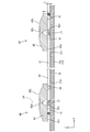
さらに、図7に示すように、6列目と7列目に位置する拡散レンズ40,40に係止される反射シート保持部材30は、リベット20により保持されない、6列目と7列目に位置する拡散レンズ40,40をそれぞれ挿通するレンズ挿通孔21d,21dの間をシャーシ14に対して保持する構成とされている。ここで、6列目に配される拡散レンズ40は、X軸方向に3枚並んで配されるLED基板18のうち、左側に配されるLED基板18-1に固定されるとともに、7列目に配される拡散レンズ40は、X軸方向に3枚並んで配されるLED基板18のうち、中央に配されるLED基板18-2に固定されている。そして、LED基板18-1と、LED基板18-2とはコネクタ部18aを介して接続されている。また、反射シート21には、6列目と7列目に位置する拡散レンズ40,40をそれぞれ挿通するレンズ挿通孔21d,21dの間にコネクタ部18aを挿通するコネクタ挿通孔21eが設けられている。そして、反射シート保持部材30は、当該コネクタ挿通孔21eの孔縁と重畳するように配されている。なお、当該コネクタ部18aは、環状をなす反射シート保持部材30の周内に配されており、コネクタ部18aと反射シート保持部材30とが干渉することはない。11列目と12列目に位置する拡散レンズ40,40に係止される反射シート保持部材30は、6列目と7列目に位置する拡散レンズ40,40に係止される反射シート保持部材30と同様の配置構成であるため、説明を省略する。
Further, as shown in FIG. 7, the reflection sheet holding members 30 locked to the diffusion lenses 40, 40 located in the sixth and seventh rows are not held by the rivets 20, and are held in the sixth and seventh rows. The configuration is such that the space between the lens insertion holes 21d and 21d through which the diffused lenses 40 and 40 are positioned is held with respect to the chassis 14. Here, the diffusion lens 40 arranged in the sixth row is fixed to the LED substrate 18-1 arranged on the left side among the LED substrates 18 arranged in a row in the X-axis direction, and the seventh row. The diffusion lens 40 disposed in the eye is fixed to the LED substrate 18-2 disposed in the center among the LED substrates 18 disposed in a line in the X-axis direction. The LED board 18-1 and the LED board 18-2 are connected via the connector portion 18a. The reflection sheet 21 is provided with a connector insertion hole 21e for inserting the connector portion 18a between the lens insertion holes 21d and 21d for inserting the diffusion lenses 40 and 40 located in the sixth row and the seventh row, respectively. Yes. And the reflection sheet holding member 30 is distribute | arranged so that it may overlap with the hole edge of the said connector penetration hole 21e. In addition, the said connector part 18a is distribute | arranged in the circumference | surroundings of the reflection sheet holding member 30 which makes | forms an annular shape, and the connector part 18a and the reflection sheet holding member 30 do not interfere. The reflection sheet holding member 30 locked to the diffusion lenses 40 and 40 located in the 11th and 12th rows is the reflection sheet holding member locked to the diffusion lenses 40 and 40 located in the 6th and 7th rows. Since the configuration is the same as that of the member 30, the description thereof is omitted.
本実施形態のバックライト装置12は、複数のLED17と、板状部材であって、その板面上にLED17が配されるシャーシ14と、シャーシ14に対して固定されるとともに、LED17をシャーシ14と反対側から個別に覆い、LED14からの光に対して光学的な作用を及ぼす複数の拡散レンズ40と、シャーシ14の板面を覆う反射シート21であって、LED17を露出するとともに、拡散レンズ40を挿通するレンズ挿通孔21dを有する反射シート21と、反射シート21をシャーシ14と反対側から保持する反射シート保持部材30であって、隣り合う拡散レンズ40,40に係止されるとともに、隣り合う拡散レンズ40,40の間において、反射シート21のシート面上に延設される反射シート保持部材30と、を備える。
The backlight device 12 of the present embodiment includes a plurality of LEDs 17 and a plate-like member. The chassis 14 has the LEDs 17 arranged on the plate surface thereof, and is fixed to the chassis 14. A plurality of diffusing lenses 40 that individually cover from the opposite side of the LED 14 and have an optical effect on the light from the LED 14, and a reflective sheet 21 that covers the plate surface of the chassis 14, exposing the LED 17, and the diffusing lens A reflection sheet 21 having a lens insertion hole 21d for inserting 40, and a reflection sheet holding member 30 for holding the reflection sheet 21 from the opposite side of the chassis 14, and is locked to adjacent diffusion lenses 40, 40; A reflection sheet holding member 30 extending on the sheet surface of the reflection sheet 21 between the adjacent diffuser lenses 40, 40; Obtain.
本実施形態のバックライト装置12では、反射シート保持部材30がシャーシ14に対して固定される拡散レンズ40に係止されるとともに、隣り合う拡散レンズ40,40の間において、反射シート21のシート面上に延設されるから、反射シート21の隣り合うレンズ挿通孔21d,21dの間に亘って、当該反射シート21をシャーシ14と反対側から保持することができる。このため、レンズ挿通孔21dの開口縁の反りを抑制するとともに、反射シート21をシャーシ14に対して保持することができ、輝度ムラの発生を低減することができる。
In the backlight device 12 of the present embodiment, the reflection sheet holding member 30 is locked to the diffusion lens 40 fixed to the chassis 14, and between the adjacent diffusion lenses 40, 40, the sheet of the reflection sheet 21. Since it extends on the surface, the reflection sheet 21 can be held from the side opposite to the chassis 14 across the adjacent lens insertion holes 21 d and 21 d of the reflection sheet 21. For this reason, while suppressing the curvature of the opening edge of 21 d of lens insertion holes, the reflective sheet 21 can be hold | maintained with respect to the chassis 14, and generation | occurrence | production of a brightness nonuniformity can be reduced.
具体的には、レンズ挿通孔21dの孔縁部分は、反射シート21の中で最もLED17に対して近接して配されており、LED17からの熱により、膨張・収縮しやすくなっている。レンズ挿通孔21dの孔縁部分が、膨張・収縮した場合には、当該部分がシャーシ14と反対側に反り変形し、当該反り部分がLED17からの光の光路上に進入し、影となる虞がある。しかしながら、本実施形態では、反射シート保持部材30はレンズ挿通孔21dの孔縁をシャーシ14と反対側から押える構成とされており、レンズ挿通孔21dの開口縁の反りを抑制することができる。
さらに、反射シート21は、その底部21aがシャーシ14の底板14aを覆うように敷設されているが、各部材の寸法誤差や組付誤差に起因して、反射シート21の底部21aが配される敷設面に段差や凹凸ができることがある。このような敷設面に、反射シート21の底部21aを配すると、当該段差や凹凸に起因して反射シート21の一部がシャーシ14から浮き上がり、LED17からの光が反射シート21の裏面側に進入する虞がある。しかしながら、本実施形態では、反射シート保持部材30が、反射シート21をシャーシ14と反対側から押える構成とされており、反射シート21が浮き上がることを抑制することができる。 Specifically, the hole edge portion of thelens insertion hole 21 d is disposed closest to the LED 17 in the reflection sheet 21, and is easily expanded and contracted by the heat from the LED 17. When the hole edge portion of the lens insertion hole 21d expands and contracts, the portion warps and deforms on the opposite side of the chassis 14, and the warped portion enters the optical path of light from the LED 17 and may become a shadow. There is. However, in the present embodiment, the reflection sheet holding member 30 is configured to press the hole edge of the lens insertion hole 21d from the side opposite to the chassis 14 and suppress warping of the opening edge of the lens insertion hole 21d.
Furthermore, although thereflection sheet 21 is laid so that the bottom 21a covers the bottom plate 14a of the chassis 14, the bottom 21a of the reflection sheet 21 is disposed due to dimensional errors and assembly errors of each member. There may be steps or irregularities on the laying surface. When the bottom portion 21a of the reflection sheet 21 is arranged on such a laying surface, a part of the reflection sheet 21 is lifted from the chassis 14 due to the steps and irregularities, and the light from the LED 17 enters the back side of the reflection sheet 21. There is a risk of doing. However, in the present embodiment, the reflection sheet holding member 30 is configured to press the reflection sheet 21 from the side opposite to the chassis 14, and the reflection sheet 21 can be prevented from floating.
さらに、反射シート21は、その底部21aがシャーシ14の底板14aを覆うように敷設されているが、各部材の寸法誤差や組付誤差に起因して、反射シート21の底部21aが配される敷設面に段差や凹凸ができることがある。このような敷設面に、反射シート21の底部21aを配すると、当該段差や凹凸に起因して反射シート21の一部がシャーシ14から浮き上がり、LED17からの光が反射シート21の裏面側に進入する虞がある。しかしながら、本実施形態では、反射シート保持部材30が、反射シート21をシャーシ14と反対側から押える構成とされており、反射シート21が浮き上がることを抑制することができる。 Specifically, the hole edge portion of the
Furthermore, although the
本実施形態では、シャーシ14に対して固定され、LED17が実装されるとともに拡散レンズ40が固定されるLED基板18を備える。このため、LED基板18をシャーシ14に対して固定することにより、シャーシ14に対して拡散レンズ40を容易に固定することができる。具体的には、LED基板18に対して拡散レンズ40を固着するとともに、シャーシ14に対して当該LED基板18をリベット20で固定することにより、拡散レンズ40のシャーシ14に対する固定を実現することができる。
In this embodiment, the LED board 18 is fixed to the chassis 14, the LED 17 is mounted, and the diffusion lens 40 is fixed. For this reason, the diffusion lens 40 can be easily fixed to the chassis 14 by fixing the LED substrate 18 to the chassis 14. Specifically, the diffusion lens 40 can be fixed to the chassis 14 by fixing the diffusion lens 40 to the LED board 18 and fixing the LED board 18 to the chassis 14 with the rivets 20. it can.
本実施形態では、拡散レンズ40は、柱状をなす取付脚部41を有し、当該取付脚部41がLED基板18に対して固定されており、反射シート保持部材30は、取付脚部41に係止されている。このため、反射シート保持部材30を拡散レンズ40に容易に係止させることができる。
In the present embodiment, the diffusing lens 40 has a mounting leg portion 41 having a columnar shape, the mounting leg portion 41 is fixed to the LED substrate 18, and the reflective sheet holding member 30 is attached to the mounting leg portion 41. It is locked. For this reason, the reflection sheet holding member 30 can be easily locked to the diffusion lens 40.
本実施形態では、拡散レンズ40は、取付脚部41に支持されるとともに、当該取付脚部41から庇状に延びるレンズ部42を有し、反射シート保持部材30は、レンズ部42に係止されている。このため、反射シート保持部材30が拡散レンズ40のレンズ部42側に、脱落することを抑制することができる。
In the present embodiment, the diffusing lens 40 is supported by the mounting leg 41 and has a lens part 42 extending from the mounting leg 41 in a bowl shape, and the reflection sheet holding member 30 is locked to the lens part 42. Has been. For this reason, it is possible to suppress the reflection sheet holding member 30 from falling off to the lens portion 42 side of the diffusing lens 40.
本実施形態では、反射シート保持部材30は、その幅寸法が、反射シート21のシート面と、当該シート面に対向するレンズ部42の光入射面42aとの離間距離と略同じ寸法とされてなる。このため、レンズ部42により、反射シート保持部材30を反射シート21に対して位置決めすることができ、反射シート21の保持を好適に実現することができる。
In the present embodiment, the width of the reflection sheet holding member 30 is substantially the same as the distance between the sheet surface of the reflection sheet 21 and the light incident surface 42a of the lens unit 42 facing the sheet surface. Become. For this reason, the reflection sheet holding member 30 can be positioned with respect to the reflection sheet 21 by the lens portion 42, and the holding of the reflection sheet 21 can be suitably realized.
本実施形態では、反射シート保持部材30は、弾性を有する、環状部材とされており、隣り合う拡散レンズ40,40を取り囲むように配されるとともに、周方向に収縮しようとする弾発力により拡散レンズ40に係止されている。このため、反射シート保持部材30をその弾発力により、拡散レンズ40に確実に係止させることができ、反射シート21の保持を好適に実現することができる。
In the present embodiment, the reflection sheet holding member 30 is an annular member having elasticity, and is disposed so as to surround the adjacent diffusion lenses 40 and 40, and by the elastic force that tends to contract in the circumferential direction. Locked to the diffusing lens 40. For this reason, the reflecting sheet holding member 30 can be reliably locked to the diffusion lens 40 by its elastic force, and the holding of the reflecting sheet 21 can be suitably realized.
本実施形態では、反射シート保持部材30は、行列配置された拡散レンズ40のうち、端部に位置する拡散レンズ40Eに係止されている。このため、バックライト装置12の狭額縁化に伴い、リベット等の反射シート21を保持する部材を反射シート21の端部に配することができない場合であっても、反射シート21の端部側において、反射シート21が浮き上がることを抑制することができる。
In the present embodiment, the reflection sheet holding member 30 is locked to the diffusion lens 40E located at the end of the diffusion lenses 40 arranged in a matrix. For this reason, even when the member that holds the reflection sheet 21 such as a rivet cannot be arranged at the end of the reflection sheet 21 due to the narrowing of the frame of the backlight device 12, the end side of the reflection sheet 21 , The reflection sheet 21 can be prevented from floating.
本実施形態では、LED基板18は、隣り合う拡散レンズ40,40のうち、一方の拡散レンズ40が固定される一のLED基板18-1と、他方の拡散レンズ40が固定される他のLED基板18-2と、で分割構成されている。このような構成により、2つのLED基板18-1,18-2の寸法誤差や反りにより、2つのLED基板18-1,18-2の間に高低差が生じた場合であっても、反射シート保持部材30を配することにより、高低差に起因して反射シート21が浮き上がることを抑制することができる。
In the present embodiment, the LED substrate 18 includes one LED substrate 18-1 to which one of the diffusion lenses 40, 40 is fixed, and another LED to which the other diffusion lens 40 is fixed. The substrate 18-2 is divided. With such a configuration, even if a height difference occurs between the two LED boards 18-1 and 18-2 due to a dimensional error or warpage of the two LED boards 18-1 and 18-2, reflection is caused. By disposing the sheet holding member 30, it is possible to suppress the reflection sheet 21 from being lifted due to the height difference.
本実施形態では、反射シート保持部材30は、コネクタ挿通孔21eの孔縁と重畳するように配されているから、コネクタ挿通孔21eの孔縁において、反射シート14が浮き上がることを抑制することができる。
In the present embodiment, since the reflection sheet holding member 30 is arranged so as to overlap with the hole edge of the connector insertion hole 21e, it is possible to suppress the reflection sheet 14 from floating at the hole edge of the connector insertion hole 21e. it can.
本実施形態では、光学素子は、LED17からの光を拡散させる拡散レンズ40とされるから、より一層、輝度ムラを低減させることができる。
In this embodiment, since the optical element is the diffusing lens 40 that diffuses the light from the LED 17, the luminance unevenness can be further reduced.
<実施形態2>
本発明の実施形態2を図10および図11によって説明する。この実施形態2では、反射シート保持部材30構成を変更した反射シート保持部材130を示す。なお、上記した実施形態と同様の構造、作用及び効果について重複する説明は省略する。 <Embodiment 2>
A second embodiment of the present invention will be described with reference to FIGS. In this Embodiment 2, the reflectivesheet holding member 130 which changed the reflective sheet holding member 30 structure is shown. In addition, the description which overlaps about the structure, an effect | action, and effect similar to above-described embodiment is abbreviate | omitted.
本発明の実施形態2を図10および図11によって説明する。この実施形態2では、反射シート保持部材30構成を変更した反射シート保持部材130を示す。なお、上記した実施形態と同様の構造、作用及び効果について重複する説明は省略する。 <Embodiment 2>
A second embodiment of the present invention will be described with reference to FIGS. In this Embodiment 2, the reflective
反射シート保持部材130は、図10および図11に示すように、反射性に優れた、プラスチック等の合成樹脂製とされている。反射シート保持部材130は、その両端部にそれぞれ配され、取付脚部41の外周を把持する2つの把持部131,131と、2つの把持部131,131を連結するシート押え部132と、を有するものとされている。把持部131は、反射シート保持部材130の長さ方向と交差する方向、詳しくは、直交する方向に開口するU字状をなし、対向する内周面の幅が取付脚部41の径と一致するものとされている。そして、2つの把持部131,131は互いに反対側に開口するものとされている。反射シート保持部材130の長手寸法は、2つの把持部131,131がそれぞれ把持する取付脚部41,41の離間距離と同じものとされている。そして、反射シート保持部材130は、その幅寸法Wが、反射シート21のシート面と、当該シート面に対向するレンズ部42の庇状部分をなす光入射面42aとの離間距離Lと略同じ寸法とされている。
As shown in FIGS. 10 and 11, the reflection sheet holding member 130 is made of a synthetic resin such as plastic having excellent reflectivity. The reflection sheet holding member 130 is disposed at both ends thereof, and includes two gripping portions 131 and 131 that grip the outer periphery of the mounting leg portion 41, and a sheet pressing portion 132 that connects the two gripping portions 131 and 131. It is supposed to have. The grip portion 131 has a U-shape that opens in a direction intersecting the length direction of the reflection sheet holding member 130, specifically, an orthogonal direction, and the width of the opposed inner peripheral surface matches the diameter of the mounting leg portion 41. It is supposed to be. The two gripping portions 131 and 131 are opened to opposite sides. The longitudinal dimension of the reflection sheet holding member 130 is the same as the distance between the mounting leg portions 41 and 41 held by the two holding portions 131 and 131, respectively. The width W of the reflection sheet holding member 130 is substantially the same as the separation distance L between the sheet surface of the reflection sheet 21 and the light incident surface 42a that forms the bowl-shaped portion of the lens portion 42 facing the sheet surface. It is a dimension.
反射シート保持部材130は、図10および図11に示すように、シャーシ14内において、X軸方向に隣り合う拡散レンズ40,40に係止されている。詳しくは、反射シート保持部材30の把持部131,131は、拡散レンズ40の3つの取付脚部41のうち、互いに隣接する拡散レンズ40に最も近接して配される取付脚部41をそれぞれ把持するものとされている。そして、反射シート保持部材130は、幅方向(Z軸方向)においては、レンズ部42の庇状に張り出した部分に係止されている。さらに、反射シート保持部材130は、拡散レンズ40と重畳する部分においては、レンズ部42の光入射面42aに当接するとともに、隣り合うレンズ挿通孔21dの間においては、反射シート21の上側(シャーシ14と反対側)のシート面に当接するものとされている。すなわち、反射シート保持部材130は、レンズ挿通孔21dの孔縁をレンズ部42側(シャーシ14と反対側)から押える構成とされている。
As shown in FIGS. 10 and 11, the reflection sheet holding member 130 is locked to the diffusion lenses 40, 40 adjacent in the X-axis direction in the chassis 14. Specifically, the gripping portions 131 and 131 of the reflection sheet holding member 30 respectively grip the mounting leg portions 41 arranged closest to the diffusion lenses 40 adjacent to each other among the three mounting leg portions 41 of the diffusion lens 40. It is supposed to be. The reflection sheet holding member 130 is locked to the protruding portion of the lens portion 42 in the width direction (Z-axis direction). Further, the reflection sheet holding member 130 is in contact with the light incident surface 42a of the lens portion 42 at a portion overlapping with the diffusing lens 40, and between the adjacent lens insertion holes 21d (on the chassis (chassis)). 14 on the opposite side). That is, the reflection sheet holding member 130 is configured to press the hole edge of the lens insertion hole 21d from the lens portion 42 side (the side opposite to the chassis 14).
本実施形態では、反射シート保持部材130は、その両端部にそれぞれ配され、取付脚部41の外周を把持する2つの把持部131,131と、2つの把持部131,131を連結するシート押え部132と、を有する。このため、把持部131により拡散レンズ40に確実に係止されるとともに、シート押え部132により反射シート21を保持することができ、反射シート21の保持を好適に実現することができる。
In the present embodiment, the reflection sheet holding member 130 is disposed at both ends thereof, and the two holding parts 131 and 131 that hold the outer periphery of the mounting leg 41 and the sheet presser that connects the two holding parts 131 and 131. Part 132. For this reason, while being reliably latched by the diffusing lens 40 by the holding part 131, the reflection sheet 21 can be hold | maintained by the sheet pressing part 132, and holding | maintenance of the reflection sheet 21 can be implement | achieved suitably.
<実施形態3>
本発明の実施形態3を図12によって説明する。この実施形態3では、実施形態2の反射シート保持部材130の構成を変更した反射シート保持部材230を示す。なお、上記した実施形態と同様の構造、作用及び効果について重複する説明は省略する。 <Embodiment 3>
A third embodiment of the present invention will be described with reference to FIG. In the third embodiment, a reflectionsheet holding member 230 in which the configuration of the reflection sheet holding member 130 of the second embodiment is changed is shown. In addition, the description which overlaps about the structure, an effect | action, and effect similar to above-described embodiment is abbreviate | omitted.
本発明の実施形態3を図12によって説明する。この実施形態3では、実施形態2の反射シート保持部材130の構成を変更した反射シート保持部材230を示す。なお、上記した実施形態と同様の構造、作用及び効果について重複する説明は省略する。 <Embodiment 3>
A third embodiment of the present invention will be described with reference to FIG. In the third embodiment, a reflection
反射シート保持部材230は、図12に示すように、反射性に優れた、プラスチック等の合成樹脂製とされており、その両端部にそれぞれ配され、取付脚部41の外周を把持する2つの把持部231,231と、2つの把持部231,231を連結するシート押え部232と、を有するものとされている。把持部231は、反射シート保持部材230の長さ方向と交差する方向、詳しくは、直交する方向に開口するU字状をなし、対向する内周面の幅が取付脚部41の径と一致するものとされている。そして、2つの把持部231,231は互いに同じ側に開口するものとされている。反射シート保持部材30の長手寸法は、2つの把持部231,231がそれぞれ把持する取付脚部41,41の離間距離と同じものとされている。
As shown in FIG. 12, the reflection sheet holding member 230 is made of a synthetic resin such as plastic having excellent reflectivity. The reflection sheet holding member 230 is disposed at both ends of the reflection sheet holding member 230 and holds the outer periphery of the mounting leg portion 41. The gripping portions 231 and 231 and the sheet pressing portion 232 connecting the two gripping portions 231 and 231 are provided. The grip portion 231 has a U-shape that opens in a direction intersecting the length direction of the reflection sheet holding member 230, specifically, an orthogonal direction, and the width of the opposed inner peripheral surface matches the diameter of the mounting leg portion 41. It is supposed to be. The two grip portions 231 and 231 are opened on the same side. The longitudinal dimension of the reflection sheet holding member 30 is the same as the distance between the mounting leg portions 41 and 41 held by the two holding portions 231 and 231.
反射シート保持部材230は、図12に示すように、シャーシ14内において、Y軸方向に隣り合う拡散レンズ40,40に係止されている。なお、当該隣り合う拡散レンズ40,40はそれぞれ異なるLED基板18に固定されている。
As shown in FIG. 12, the reflection sheet holding member 230 is locked to the diffusion lenses 40, 40 adjacent in the Y-axis direction in the chassis 14. The adjacent diffusing lenses 40 are fixed to different LED substrates 18 respectively.
本実施形態では、反射シート保持部材230は、2つの把持部231,231によって係止されており、実施形態1に示した反射シート保持部材30のように、その係止される拡散レンズ40,40を互いに近づける方向に弾発力が生じることがない。このため、互いに異なるLED基板18に固定される拡散レンズ40,40とに係止される場合であっても、反射シート保持部材230の弾発力によりLED基板18がシャーシ14内において位置ズレする虞がない。
In the present embodiment, the reflection sheet holding member 230 is locked by the two gripping portions 231 and 231, and like the reflection sheet holding member 30 shown in the first embodiment, the locked diffusion lens 40, Elasticity does not occur in the direction in which the 40 is brought close to each other. For this reason, even if it is a case where it is latched by diffuser lenses 40 and 40 fixed to mutually different LED boards 18, LED board 18 shifts in position in chassis 14 by the elastic force of reflective sheet holding member 230. There is no fear.
<実施形態4>
本発明の実施形態4を図13によって説明する。この実施形態4では、LED基板18の構成を変更したLED基板318-1,318-2を示す。なお、上記した実施形態と同様の構造、作用及び効果について重複する説明は省略する。 <Embodiment 4>
A fourth embodiment of the present invention will be described with reference to FIG. In the fourth embodiment, LED substrates 318-1 and 318-2 in which the configuration of theLED substrate 18 is changed are shown. In addition, the description which overlaps about the structure, an effect | action, and effect similar to above-described embodiment is abbreviate | omitted.
本発明の実施形態4を図13によって説明する。この実施形態4では、LED基板18の構成を変更したLED基板318-1,318-2を示す。なお、上記した実施形態と同様の構造、作用及び効果について重複する説明は省略する。 <Embodiment 4>
A fourth embodiment of the present invention will be described with reference to FIG. In the fourth embodiment, LED substrates 318-1 and 318-2 in which the configuration of the
本実施形態では、反射シート保持部材30は、リベット20により保持されない、中央部に配される拡散レンズ40,40をそれぞれ挿通するレンズ挿通孔21d,21dの間をシャーシ14に対して保持する構成とされている。ここで、当該拡散レンズ40,40のうち左側の拡散レンズ40は、X軸方向の左側に配されるLED基板318-1に固定されている。また、当該拡散レンズ40,40のうち右側の拡散レンズ40は、X軸方向の右側に配されるLED基板318-2に固定されている。そして、LED基板318-1と、LED基板318-2とはコネクタ部等により接続されていない。言い換えれば、LED基板318-1と、LED基板318-2とは対向状に配される端部同士が、互いに接続されない構成とされている。
In the present embodiment, the reflective sheet holding member 30 is configured to hold the chassis 14 between the lens insertion holes 21d and 21d that are not held by the rivet 20 and are inserted through the diffusion lenses 40 and 40 disposed in the center portion, respectively. It is said that. Here, of the diffusion lenses 40, 40, the left diffusion lens 40 is fixed to the LED substrate 318-1 disposed on the left side in the X-axis direction. The right diffusion lens 40 of the diffusion lenses 40 is fixed to the LED substrate 318-2 arranged on the right side in the X-axis direction. The LED board 318-1 and the LED board 318-2 are not connected by a connector portion or the like. In other words, the LED substrate 318-1 and the LED substrate 318-2 are configured such that the end portions arranged opposite to each other are not connected to each other.
本実施形態では、リベット20により保持されない、2枚のLED基板の間の部分において、反射シート保持部材30により、反射シート21を保持することができる。
In the present embodiment, the reflection sheet 21 can be held by the reflection sheet holding member 30 in a portion between the two LED substrates that is not held by the rivet 20.
<実施形態5>
本発明の実施形態5を図14によって説明する。この実施形態5では、リベット20が反射シート21をシャーシ14に対して保持しないリベット420Cを含むものを示す。なお、上記した実施形態と同様の構造、作用及び効果について重複する説明は省略する。 <Embodiment 5>
Embodiment 5 of the present invention will be described with reference to FIG. In the fifth embodiment, therivet 20 includes a rivet 420 </ b> C that does not hold the reflection sheet 21 with respect to the chassis 14. In addition, the description which overlaps about the structure, an effect | action, and effect similar to above-described embodiment is abbreviate | omitted.
本発明の実施形態5を図14によって説明する。この実施形態5では、リベット20が反射シート21をシャーシ14に対して保持しないリベット420Cを含むものを示す。なお、上記した実施形態と同様の構造、作用及び効果について重複する説明は省略する。 <Embodiment 5>
Embodiment 5 of the present invention will be described with reference to FIG. In the fifth embodiment, the
リベット20のうち、リベット420Cは、リベット20Aと同様の部品とされるものの、当該リベット420Cに対応して設けられてリベット挿通孔21fが押え部20dの径より大きいものとされている点で、リベット20Aと異なる種類とされている。すなわち、リベット20Aは、その押え部20dとシャーシ14とにより反射シート21を挟持するものとされていたが、リベット420Cは押え部20dが反射シート21に設けられたリベット挿通孔21fに挿通するものとされており、反射シート21をシャーシ14に対して保持しない構成とされている。当該リベット420Cによれば、反射シート21をシャーシ14に敷設する前に、LED基板18をリベット420Cにより仮にシャーシ14に対して取り付けることができる。そして、当該リベット420Cの押え部20dを反射シート21のリベット挿通孔21fに挿通させることにより、反射シート21と押え部20dとが干渉する事態を回避することができる。
Of the rivets 20, the rivet 420C is a component similar to the rivet 20A, but the rivet insertion hole 21f is provided corresponding to the rivet 420C and is larger than the diameter of the pressing portion 20d. The type is different from the rivet 20A. That is, the rivet 20A is configured such that the reflection sheet 21 is sandwiched between the holding portion 20d and the chassis 14, but the rivet 420C is inserted into the rivet insertion hole 21f provided in the reflection sheet 21 in the rivet 420C. The reflection sheet 21 is not held with respect to the chassis 14. According to the rivet 420C, the LED substrate 18 can be temporarily attached to the chassis 14 by the rivet 420C before the reflection sheet 21 is laid on the chassis 14. Then, by inserting the holding portion 20d of the rivet 420C into the rivet insertion hole 21f of the reflection sheet 21, it is possible to avoid a situation where the reflection sheet 21 and the holding portion 20d interfere with each other.
本実施形態では、反射シート保持部材30は、リベット20A等により保持されない、左から2列目と3列目に位置する拡散レンズ40,40をそれぞれ挿通するレンズ挿通孔21d,21dの間をシャーシ14に対して保持する構成とされている。反射シート21には、2列目と3列目に位置する拡散レンズ40,40をそれぞれ挿通するレンズ挿通孔21d,21dの間にリベット420Cを挿通するリベット挿通孔21fが設けられている。そして、反射シート保持部材30は、当該リベット挿通孔21fの孔縁と重畳するように配されている。
In the present embodiment, the reflection sheet holding member 30 is not held by the rivet 20A or the like, and is formed between the lens insertion holes 21d and 21d through which the diffusion lenses 40 and 40 located in the second and third rows from the left are inserted. 14 for holding. The reflection sheet 21 is provided with a rivet insertion hole 21f through which the rivet 420C is inserted between the lens insertion holes 21d and 21d through which the diffusion lenses 40 and 40 located in the second and third rows are inserted, respectively. And the reflective sheet holding member 30 is distribute | arranged so that it may overlap with the hole edge of the said rivet penetration hole 21f.
本実施形態では、リベット挿通孔21fの孔縁において、反射シート21が浮き上がることを抑制することができる。
In the present embodiment, it is possible to suppress the reflection sheet 21 from floating at the hole edge of the rivet insertion hole 21f.
<他の実施形態>
本発明は上記記述及び図面によって説明した実施形態に限定されるものではなく、例えば次のような実施形態も本発明の技術的範囲に含まれる。
(1)上記した実施形態では、反射シート保持部材30,130の幅寸法Wが、反射シート21のシート面と、レンズ部42光入射面42aとの離間距離Lと略同じ寸法とされるものを例示したが、反射シート保持部材の幅寸法WはLより小さいものであってもよい。この場合には、反射シート保持部材が、LED17からの光路に与える影響を小さくすることができる。 <Other embodiments>
The present invention is not limited to the embodiments described with reference to the above description and drawings. For example, the following embodiments are also included in the technical scope of the present invention.
(1) In the above-described embodiment, the width dimension W of the reflection sheet holding members 30 and 130 is substantially the same as the distance L between the sheet surface of the reflection sheet 21 and the lens portion 42 light incident surface 42a. However, the width W of the reflection sheet holding member may be smaller than L. In this case, the influence of the reflection sheet holding member on the optical path from the LED 17 can be reduced.
本発明は上記記述及び図面によって説明した実施形態に限定されるものではなく、例えば次のような実施形態も本発明の技術的範囲に含まれる。
(1)上記した実施形態では、反射シート保持部材30,130の幅寸法Wが、反射シート21のシート面と、レンズ部42光入射面42aとの離間距離Lと略同じ寸法とされるものを例示したが、反射シート保持部材の幅寸法WはLより小さいものであってもよい。この場合には、反射シート保持部材が、LED17からの光路に与える影響を小さくすることができる。 <Other embodiments>
The present invention is not limited to the embodiments described with reference to the above description and drawings. For example, the following embodiments are also included in the technical scope of the present invention.
(1) In the above-described embodiment, the width dimension W of the reflection
(2)上記した実施形態では、反射シート保持部材30,130が、反射シート21のシート面と密着または当接するものを例示したが、これに限られない。反射シート保持部材が反射シートのシート面と離間して配されており、反射シートがシャーシと反対側に浮き上がった際に、反射シートをシャーシ側に押える構成とされてもよい。
(2) In the above-described embodiment, the reflective sheet holding members 30 and 130 are shown in close contact with or in contact with the sheet surface of the reflective sheet 21, but are not limited thereto. The reflection sheet holding member may be arranged so as to be separated from the sheet surface of the reflection sheet, and when the reflection sheet floats on the side opposite to the chassis, the reflection sheet may be pressed to the chassis side.
(3)上記した実施形態では、反射シート保持部材30は弾発力により、拡散レンズ40に係止されるものを例示したが、その他にも、接着剤等により拡散レンズ40に係止される構成であってもよい。
(3) In the above-described embodiment, the reflective sheet holding member 30 is illustrated as being locked to the diffusion lens 40 by the elastic force, but is also locked to the diffusion lens 40 by an adhesive or the like. It may be a configuration.
(4)上記した実施形態では、X軸方向において隣り合う拡散レンズ40,40に係止される反射シート保持部材30,130と、Y軸方向において隣り合う拡散レンズ40,40に係止される反射シート保持部材230とを例示したが、これに限られず、例えば、LED基板18の長手方向において、斜め方向に隣り合う拡散レンズに係止されるものであってもよい。
(4) In the above-described embodiment, the reflection sheet holding members 30 and 130 locked to the diffusion lenses 40 and 40 adjacent to each other in the X-axis direction and the diffusion lenses 40 and 40 adjacent to each other in the Y-axis direction are locked. Although the reflection sheet holding member 230 is illustrated, the present invention is not limited to this, and for example, the reflection sheet holding member 230 may be engaged with a diffusion lens adjacent in the oblique direction in the longitudinal direction of the LED substrate 18.
(5)上記した実施形態では、反射シート保持部材は、所定の列に配される拡散レンズ40,40について、すべての行において係止される構成としたが、例えば、所定の行のみに配される構成としてもよい。また、反射シート保持部材は、予め係止される箇所が設定されていなくてもよく、反射シートを組み付けた後に、検査等により反射シートの浮き上がりが認められた箇所に、適宜係止するものとしてもよい。
(5) In the above-described embodiment, the reflection sheet holding member is configured to be locked in all rows with respect to the diffusion lenses 40, 40 arranged in a predetermined column. It is good also as a structure to be made. In addition, the reflection sheet holding member does not have to be set in advance, and after the reflection sheet is assembled, the reflection sheet holding member is appropriately locked at a position where the reflection sheet is lifted by inspection or the like. Also good.
(6)上記実施形態においては、取付脚部41は円柱状をなすものを例示したが、この形状に限られず、角柱状や、LEDを取り囲む円筒状等であってもよい。
(6) In the above embodiment, the mounting leg portion 41 is exemplified as a columnar shape, but is not limited to this shape, and may be a prismatic shape, a cylindrical shape surrounding the LED, or the like.
(7)上記実施形態においては、取付脚部41は3つが、正三角形をなす配置にて設けられているものを例示したが、数および配置構成はこれに限られない。
(7) In the above-described embodiment, the three attachment leg portions 41 are provided in an arrangement that forms an equilateral triangle, but the number and arrangement configuration are not limited thereto.
(8)上記実施形態においては、レンズ部42が取付脚部から庇状に延びる形状を例示したが、レンズ部の形状はこれに限られない。
(8) In the above embodiment, the shape of the lens portion 42 extending in a bowl shape from the mounting leg portion is exemplified, but the shape of the lens portion is not limited thereto.
(9)上記実施形態においては、光学素子として、拡散レンズ50,250を例示したが、これに限定されない。光学素子は、光源からの光に対して光学的な作用を及ぼすものであればよく、例えば、集光レンズなどを用いてもよい。
(9) In the above embodiment, the diffusion lenses 50 and 250 are exemplified as the optical elements, but the present invention is not limited to this. The optical element only needs to have an optical effect on the light from the light source. For example, a condensing lens may be used.
(10)上記した実施形態では、LED基板は分割構成されるものを例示したが、LED基板は1枚で構成されていてもよく、また、LEDが行列配置される矩形状のLED基板を複数組み合わせて構成されていてもよい。
(10) In the above-described embodiment, the LED substrate is illustrated as being divided. However, the LED substrate may be composed of one piece, and a plurality of rectangular LED substrates on which LEDs are arranged in a matrix are provided. It may be configured in combination.
(11)上記した各実施形態では、LED基板として5個実装タイプ、6個実装タイプ及び8個実装タイプのものを適宜に組み合わせて用いる旨を説明したが、5個,6個,8個以外の数のLEDを実装したLED基板を用いるようにしたものも本発明に含まれる。
(11) In each of the above-described embodiments, it has been described that the LED board is used in an appropriate combination of the five-mounting type, the six-mounting type, and the eight-mounting type, but other than five, six, and eight. What used the LED board which mounted the number of LED is also contained in this invention.
(12)上記した各実施形態では、光源としてLEDを用いた場合を例示したが、LED以外の種類の光源を用いてもよい。例えば、LED以外にも、冷陰極管や熱陰極管などの線状光源を用いたり、有機ELなどの面状光源を用いたりしてもよい。
(12) In each of the embodiments described above, the case where the LED is used as the light source is exemplified, but a light source of a type other than the LED may be used. For example, in addition to the LED, a linear light source such as a cold cathode tube or a hot cathode tube may be used, or a planar light source such as an organic EL may be used.
(13)上記実施形態では光学シート15bの種類として、光を拡散する機能を有する拡散シート、光を集光する機能を有するレンズシートなどを例示したが、光学シートは光を集光する機能と、光を拡散する機能とを併せもつものであってもよい。
(13) In the above embodiment, as the type of the optical sheet 15b, a diffusion sheet having a function of diffusing light, a lens sheet having a function of condensing light, and the like are exemplified, but the optical sheet has a function of condensing light. Also, it may have a function of diffusing light.
(14)上記した各実施形態では、液晶パネル及びシャーシがその短辺方向を鉛直方向と一致させた縦置き状態とされるものを例示したが、液晶パネル及びシャーシがその長辺方向を鉛直方向と一致させた縦置き状態とされるものも本発明に含まれる。
(14) In each of the above-described embodiments, the liquid crystal panel and the chassis are illustrated in a vertically placed state in which the short side direction coincides with the vertical direction, but the liquid crystal panel and the chassis have the long side direction in the vertical direction. Those that are in a vertically placed state matched with are also included in the present invention.
(15)上記した各実施形態では、液晶表示装置のスイッチング素子としてTFTを用いたが、TFT以外のスイッチング素子(例えば薄膜ダイオード(TFD))を用いた液晶表示装置にも適用可能であり、カラー表示する液晶表示装置以外にも、白黒表示する液晶表示装置にも適用可能である。
(15) In each of the embodiments described above, a TFT is used as a switching element of a liquid crystal display device. However, the present invention can also be applied to a liquid crystal display device using a switching element other than TFT (for example, a thin film diode (TFD)). In addition to the liquid crystal display device for display, the present invention can also be applied to a liquid crystal display device for monochrome display.
(16)上記した各実施形態では、表示パネルとして液晶パネルを用いた液晶表示装置を例示したが、他の種類の表示パネルを用いた表示装置にも本発明は適用可能である。
(16) In each of the above-described embodiments, the liquid crystal display device using the liquid crystal panel as the display panel has been exemplified. However, the present invention can also be applied to a display device using another type of display panel.
(17)上記した各実施形態では、チューナーを備えたテレビ受信装置を例示したが、チューナーを備えない表示装置にも本発明は適用可能である。
(17) In each of the above-described embodiments, the television receiver provided with the tuner is exemplified, but the present invention can be applied to a display device not provided with the tuner.
10...液晶表示装置(表示装置)、11...液晶パネル(表示パネル)、12...バックライト装置(照明装置)、14...シャーシ、15...光学部材、17...LED(光源)、18,318...LED基板(光源基板)、18a...コネクタ部、20...リベット、21...反射シート、21b...レンズ挿通孔(開口部)、21e...コネクタ挿通孔、21f...リベット挿通孔、30,130,230...反射シート保持部材、40...拡散レンズ(光学素子)、41...取付脚部、42...レンズ部、42a...光入射面、131,231...把持部、132,232...シート押え部、420C...リベット、TV...テレビ受信装置
DESCRIPTION OF SYMBOLS 10 ... Liquid crystal display device (display device), 11 ... Liquid crystal panel (display panel), 12 ... Backlight device (illumination device), 14 ... Chassis, 15 ... Optical member, 17. LED (light source), 18, 318 ... LED substrate (light source substrate), 18a ... connector, 20 ... rivet, 21 ... reflective sheet, 21b ... lens insertion hole (opening) ), 21e ... Connector insertion hole, 21f ... Rivet insertion hole, 30, 130, 230 ... Reflective sheet holding member, 40 ... Diffuse lens (optical element), 41 ... Mounting leg, 42 ... Lens unit, 42a ... Light incident surface, 131, 231 ... Holding unit, 132, 232 ... Sheet pressing unit, 420C ... Rivet, TV ... Television receiver
Claims (15)
- 複数の光源と、
板状部材であって、その板面上に前記光源が配されるシャーシと、
前記シャーシに対して固定されるとともに、前記光源を前記シャーシと反対側から個別に覆い、前記光源からの光に対して光学的な作用を及ぼす複数の光学素子と、
前記シャーシの前記板面を覆う反射シートであって、前記光源を露出するとともに、前記光学素子を挿通する開口部を有する反射シートと、
前記反射シートを前記シャーシと反対側から保持する反射シート保持部材であって、隣り合う前記光学素子に係止されるとともに、当該隣り合う前記光学素子の間において、前記反射シートのシート面上に延設される反射シート保持部材と、を備える照明装置。 Multiple light sources;
A chassis in which the light source is disposed on the plate surface,
A plurality of optical elements fixed to the chassis, individually covering the light source from the opposite side of the chassis, and optically acting on the light from the light source;
A reflective sheet that covers the plate surface of the chassis, exposing the light source and having an opening through which the optical element is inserted; and
A reflection sheet holding member that holds the reflection sheet from the opposite side of the chassis, and is locked to the adjacent optical elements, and between the adjacent optical elements, on the sheet surface of the reflection sheet And a reflecting sheet holding member extended. - 前記シャーシに対して固定され、前記光源が実装されるとともに前記光源素子とが固定される光源基板を備える請求項1に記載の照明装置。 The lighting device according to claim 1, further comprising: a light source substrate fixed to the chassis, on which the light source is mounted and on which the light source element is fixed.
- 前記光学素子は、柱状をなす取付脚部を有し、当該取付脚部が前記光源基板に対して固定されており、
前記反射シート保持部材は、前記取付脚部に係止されている請求項2に記載の照明装置。 The optical element has a columnar mounting leg, and the mounting leg is fixed to the light source substrate,
The lighting device according to claim 2, wherein the reflection sheet holding member is locked to the mounting leg portion. - 前記光学素子は、前記取付脚部に支持されるとともに、当該取付脚部から庇状に延びるレンズ部を有し、
前記反射シート保持部材は、前記レンズ部に係止されている請求項3に記載の照明装置。 The optical element has a lens portion that is supported by the mounting leg and extends in a bowl shape from the mounting leg.
The lighting device according to claim 3, wherein the reflection sheet holding member is locked to the lens unit. - 前記反射シート保持部材は、その幅寸法が、前記反射シートのシート面と、当該シート面に対向する前記レンズ部の前記庇状部分との離間距離と略同じ寸法とされてなる請求項4に記載の照明装置。 The width of the reflection sheet holding member is substantially the same as the distance between the sheet surface of the reflection sheet and the flange-shaped portion of the lens portion facing the sheet surface. The lighting device described.
- 前記反射シート保持部材は、弾性を有する、環状部材とされており、前記隣り合う前記光学素子を取り囲むように配されるとともに、周方向に収縮しようとする弾発力により前記光学素子に係止されている請求項1から請求項5のいずれか1項に記載の照明装置。 The reflection sheet holding member is an annular member having elasticity, and is disposed so as to surround the adjacent optical elements, and is also locked to the optical elements by a resilient force that tends to contract in the circumferential direction. The lighting device according to any one of claims 1 to 5, wherein
- 前記反射シート保持部材は、その両端部にそれぞれ配され、前記取付脚部の外周を把持する2つの把持部と、前記2つの把持部を連結するシート押え部と、を有する請求項3から請求項5のいずれか1項に記載の照明装置。 The said reflection sheet holding member is distribute | arranged to the both ends, respectively, It has two holding parts which hold | grip the outer periphery of the said attachment leg part, and a sheet | seat press part which connects the said two holding parts. Item 6. The lighting device according to any one of Items 5.
- 前記光学素子は、前記シャーシ内に行列配置されており、
前記反射シート保持部材は、前記行列配置された前記光学素子のうち、端部に位置する前記光学素子に係止されている請求項1から請求項7に記載の照明装置。 The optical elements are arranged in a matrix in the chassis,
The lighting device according to claim 1, wherein the reflection sheet holding member is locked to the optical element located at an end of the optical elements arranged in a matrix. - 前記光源基板は、前記隣り合う前記光学素子のうち、一方の光学素子が固定される一の光源基板と、他方の光学素子が固定される他の光源基板と、で分割構成されている請求項2から請求項5のいずれか1項に記載の照明装置。 The said light source substrate is divided | segmented and comprised by the one light source substrate to which one optical element is fixed among the said adjacent optical elements, and the other light source substrate to which the other optical element is fixed. The lighting device according to any one of claims 2 to 5.
- 前記一の光源基板と前記他の光源基板とはコネクタ部を介して接続されており、
前記反射シートは、前記隣り合う前記光学素子をそれぞれ挿通する2つの前記開口部の間に前記コネクタ部を挿通するコネクタ挿通孔を有し、
前記反射シート保持部材は、前記コネクタ挿通孔の孔縁と重畳するように配されている請求項9に記載の照明装置。 The one light source board and the other light source board are connected via a connector part,
The reflection sheet has a connector insertion hole for inserting the connector portion between the two openings for inserting the adjacent optical elements, respectively.
The lighting device according to claim 9, wherein the reflection sheet holding member is disposed so as to overlap with a hole edge of the connector insertion hole. - 前記光源基板は、前記シャーシに対してリベットにより固定されており、
前記反射シートは、前記隣り合う前記光学素子をそれぞれ挿通する2つの前記開口部の間に前記リベットを挿通するリベット挿通孔を有し、
前記反射シート保持部材は、前記リベット挿通孔の孔縁と重畳するように配されている請求項2から請求項5のいずれか1項に記載の照明装置。 The light source substrate is fixed to the chassis by rivets,
The reflection sheet has a rivet insertion hole for inserting the rivet between the two openings through which the adjacent optical elements are inserted.
The lighting device according to claim 2, wherein the reflection sheet holding member is arranged so as to overlap with a hole edge of the rivet insertion hole. - 前記光学素子は、前記光源からの光を拡散させる拡散レンズとされる請求項1から請求項11のいずれか1項に記載の照明装置。 The lighting device according to any one of claims 1 to 11, wherein the optical element is a diffusing lens that diffuses light from the light source.
- 請求項1から請求項12のいずれか1項に記載の照明装置と、
前記照明装置からの光を利用して表示を行う表示パネルと、を備えることを特徴とする表示装置。 The lighting device according to any one of claims 1 to 12,
And a display panel that performs display using light from the lighting device. - 前記表示パネルが液晶を用いた液晶パネルであることを特徴とする請求項13に記載の表示装置。 The display device according to claim 13, wherein the display panel is a liquid crystal panel using liquid crystal.
- 請求項14又は請求項15に記載された表示装置を備えることを特徴とするテレビ受信装置。 A television receiver comprising the display device according to claim 14 or 15.
Priority Applications (1)
| Application Number | Priority Date | Filing Date | Title |
|---|---|---|---|
| US14/360,229 US9371980B2 (en) | 2011-11-29 | 2012-11-22 | Illumination device, display device, and television receiver device |
Applications Claiming Priority (2)
| Application Number | Priority Date | Filing Date | Title |
|---|---|---|---|
| JP2011-260504 | 2011-11-29 | ||
| JP2011260504 | 2011-11-29 |
Publications (1)
| Publication Number | Publication Date |
|---|---|
| WO2013080882A1 true WO2013080882A1 (en) | 2013-06-06 |
Family
ID=48535341
Family Applications (1)
| Application Number | Title | Priority Date | Filing Date |
|---|---|---|---|
| PCT/JP2012/080289 WO2013080882A1 (en) | 2011-11-29 | 2012-11-22 | Illumination device, display device, and television receiver device |
Country Status (2)
| Country | Link |
|---|---|
| US (1) | US9371980B2 (en) |
| WO (1) | WO2013080882A1 (en) |
Families Citing this family (4)
| Publication number | Priority date | Publication date | Assignee | Title |
|---|---|---|---|---|
| USD823271S1 (en) * | 2016-01-18 | 2018-07-17 | Xiaomi Inc. | Television receiver |
| US11550204B2 (en) * | 2019-05-08 | 2023-01-10 | Chicony Electronics Co., Ltd. | Camera and light adjustment module |
| US20220189938A1 (en) * | 2020-12-15 | 2022-06-16 | Lumileds Llc | Optical enclosures for led modules |
| KR102546988B1 (en) | 2021-06-30 | 2023-06-22 | 엘지전자 주식회사 | Display device |
Citations (3)
| Publication number | Priority date | Publication date | Assignee | Title |
|---|---|---|---|---|
| JP2010225385A (en) * | 2009-03-23 | 2010-10-07 | Victor Co Of Japan Ltd | Backlight device |
| JP2011034948A (en) * | 2009-05-22 | 2011-02-17 | Sharp Corp | Light source device, and display device |
| WO2011152133A1 (en) * | 2010-06-02 | 2011-12-08 | シャープ株式会社 | Lighting device, display device, and television receiving device |
Family Cites Families (5)
| Publication number | Priority date | Publication date | Assignee | Title |
|---|---|---|---|---|
| JP4587931B2 (en) * | 2005-10-18 | 2010-11-24 | 株式会社エンプラス | Lighting device and lighting unit |
| KR20080040878A (en) * | 2006-11-06 | 2008-05-09 | 삼성전자주식회사 | Optical lens plate, backlight unit and display device having the same |
| WO2010146916A1 (en) * | 2009-06-15 | 2010-12-23 | シャープ株式会社 | Illuminating device, display device, and television receiver |
| CN102748652A (en) * | 2012-06-06 | 2012-10-24 | 深圳市华星光电技术有限公司 | Backlight module and liquid crystal display |
| US9134007B2 (en) * | 2012-11-06 | 2015-09-15 | Darwin Precisions Corporation | Light source device |
-
2012
- 2012-11-22 WO PCT/JP2012/080289 patent/WO2013080882A1/en active Application Filing
- 2012-11-22 US US14/360,229 patent/US9371980B2/en active Active
Patent Citations (3)
| Publication number | Priority date | Publication date | Assignee | Title |
|---|---|---|---|---|
| JP2010225385A (en) * | 2009-03-23 | 2010-10-07 | Victor Co Of Japan Ltd | Backlight device |
| JP2011034948A (en) * | 2009-05-22 | 2011-02-17 | Sharp Corp | Light source device, and display device |
| WO2011152133A1 (en) * | 2010-06-02 | 2011-12-08 | シャープ株式会社 | Lighting device, display device, and television receiving device |
Also Published As
| Publication number | Publication date |
|---|---|
| US20150042897A1 (en) | 2015-02-12 |
| US9371980B2 (en) | 2016-06-21 |
Similar Documents
| Publication | Publication Date | Title |
|---|---|---|
| JP5244241B2 (en) | Light source unit, lighting device, display device, and television receiver | |
| JP5184701B2 (en) | Lighting device, display device, and television receiver | |
| US8870401B2 (en) | Lighting device, display device and television receiver | |
| JP5337883B2 (en) | Lighting device, display device, and television receiver | |
| KR101312212B1 (en) | Lighting device, display apparatus, and television receiving equipment | |
| US8848131B2 (en) | Lighting device, display device and television receiver | |
| US8908122B2 (en) | Light source unit, lighting device, display device, television receiver, and method of manufacturing reflection sheet for light source unit | |
| US20120262631A1 (en) | Lighting device, display device and television receiver | |
| WO2010146913A1 (en) | Illuminating device, display device, and television receiver | |
| WO2010146917A1 (en) | Illumination device, display device, and television receiver | |
| WO2011055635A1 (en) | Base material for light source unit, illumination device, display device, and television receiving device | |
| US8144287B2 (en) | Optical member unit, lighting device for display, display, and television receiver | |
| US20130050587A1 (en) | Lighting device, display device and television receiver | |
| WO2013051437A1 (en) | Lighting device, display device and television receiving device | |
| WO2013080882A1 (en) | Illumination device, display device, and television receiver device | |
| US8657458B2 (en) | Lighting device, display device and television receiver | |
| WO2013024714A1 (en) | Illumination device, display device, and television reception device | |
| WO2013021933A1 (en) | Lighting device, display device, and television receiver | |
| JP2013118055A (en) | Lighting apparatus, display device and tv receiving apparatus | |
| JP2013143220A (en) | Lighting system, display device, and television receiver | |
| WO2013031674A1 (en) | Illumination device, display device, and television reception device | |
| WO2011105147A1 (en) | Lighting device, display device, and television receiver | |
| WO2011013455A1 (en) | Illumination device, display device, and television receiving device | |
| WO2013021934A1 (en) | Lighting device, display device, and television receiver | |
| WO2013027647A1 (en) | Illuminating device, display device, and television receiver |
Legal Events
| Date | Code | Title | Description |
|---|---|---|---|
| 121 | Ep: the epo has been informed by wipo that ep was designated in this application |
Ref document number: 12853355 Country of ref document: EP Kind code of ref document: A1 |
|
| WWE | Wipo information: entry into national phase |
Ref document number: 14360229 Country of ref document: US |
|
| NENP | Non-entry into the national phase |
Ref country code: DE |
|
| 122 | Ep: pct application non-entry in european phase |
Ref document number: 12853355 Country of ref document: EP Kind code of ref document: A1 |
|
| NENP | Non-entry into the national phase |
Ref country code: JP |