WO2013061539A1 - 調湿装置 - Google Patents
調湿装置 Download PDFInfo
- Publication number
- WO2013061539A1 WO2013061539A1 PCT/JP2012/006608 JP2012006608W WO2013061539A1 WO 2013061539 A1 WO2013061539 A1 WO 2013061539A1 JP 2012006608 W JP2012006608 W JP 2012006608W WO 2013061539 A1 WO2013061539 A1 WO 2013061539A1
- Authority
- WO
- WIPO (PCT)
- Prior art keywords
- heat exchanger
- refrigerant
- air
- adsorption
- adsorption heat
- Prior art date
Links
Images


Classifications
-
- F—MECHANICAL ENGINEERING; LIGHTING; HEATING; WEAPONS; BLASTING
- F24—HEATING; RANGES; VENTILATING
- F24F—AIR-CONDITIONING; AIR-HUMIDIFICATION; VENTILATION; USE OF AIR CURRENTS FOR SCREENING
- F24F3/00—Air-conditioning systems in which conditioned primary air is supplied from one or more central stations to distributing units in the rooms or spaces where it may receive secondary treatment; Apparatus specially designed for such systems
- F24F3/12—Air-conditioning systems in which conditioned primary air is supplied from one or more central stations to distributing units in the rooms or spaces where it may receive secondary treatment; Apparatus specially designed for such systems characterised by the treatment of the air otherwise than by heating and cooling
- F24F3/14—Air-conditioning systems in which conditioned primary air is supplied from one or more central stations to distributing units in the rooms or spaces where it may receive secondary treatment; Apparatus specially designed for such systems characterised by the treatment of the air otherwise than by heating and cooling by humidification; by dehumidification
- F24F3/1411—Air-conditioning systems in which conditioned primary air is supplied from one or more central stations to distributing units in the rooms or spaces where it may receive secondary treatment; Apparatus specially designed for such systems characterised by the treatment of the air otherwise than by heating and cooling by humidification; by dehumidification by absorbing or adsorbing water, e.g. using an hygroscopic desiccant
- F24F3/1429—Air-conditioning systems in which conditioned primary air is supplied from one or more central stations to distributing units in the rooms or spaces where it may receive secondary treatment; Apparatus specially designed for such systems characterised by the treatment of the air otherwise than by heating and cooling by humidification; by dehumidification by absorbing or adsorbing water, e.g. using an hygroscopic desiccant alternatively operating a heat exchanger in an absorbing/adsorbing mode and a heat exchanger in a regeneration mode
-
- B—PERFORMING OPERATIONS; TRANSPORTING
- B01—PHYSICAL OR CHEMICAL PROCESSES OR APPARATUS IN GENERAL
- B01D—SEPARATION
- B01D53/00—Separation of gases or vapours; Recovering vapours of volatile solvents from gases; Chemical or biological purification of waste gases, e.g. engine exhaust gases, smoke, fumes, flue gases, aerosols
- B01D53/26—Drying gases or vapours
- B01D53/265—Drying gases or vapours by refrigeration (condensation)
-
- F—MECHANICAL ENGINEERING; LIGHTING; HEATING; WEAPONS; BLASTING
- F24—HEATING; RANGES; VENTILATING
- F24F—AIR-CONDITIONING; AIR-HUMIDIFICATION; VENTILATION; USE OF AIR CURRENTS FOR SCREENING
- F24F12/00—Use of energy recovery systems in air conditioning, ventilation or screening
- F24F12/001—Use of energy recovery systems in air conditioning, ventilation or screening with heat-exchange between supplied and exhausted air
- F24F12/002—Use of energy recovery systems in air conditioning, ventilation or screening with heat-exchange between supplied and exhausted air using an intermediate heat-transfer fluid
- F24F12/003—Use of energy recovery systems in air conditioning, ventilation or screening with heat-exchange between supplied and exhausted air using an intermediate heat-transfer fluid using a heat pump
-
- F—MECHANICAL ENGINEERING; LIGHTING; HEATING; WEAPONS; BLASTING
- F24—HEATING; RANGES; VENTILATING
- F24F—AIR-CONDITIONING; AIR-HUMIDIFICATION; VENTILATION; USE OF AIR CURRENTS FOR SCREENING
- F24F3/00—Air-conditioning systems in which conditioned primary air is supplied from one or more central stations to distributing units in the rooms or spaces where it may receive secondary treatment; Apparatus specially designed for such systems
- F24F3/12—Air-conditioning systems in which conditioned primary air is supplied from one or more central stations to distributing units in the rooms or spaces where it may receive secondary treatment; Apparatus specially designed for such systems characterised by the treatment of the air otherwise than by heating and cooling
- F24F3/14—Air-conditioning systems in which conditioned primary air is supplied from one or more central stations to distributing units in the rooms or spaces where it may receive secondary treatment; Apparatus specially designed for such systems characterised by the treatment of the air otherwise than by heating and cooling by humidification; by dehumidification
- F24F3/1405—Air-conditioning systems in which conditioned primary air is supplied from one or more central stations to distributing units in the rooms or spaces where it may receive secondary treatment; Apparatus specially designed for such systems characterised by the treatment of the air otherwise than by heating and cooling by humidification; by dehumidification in which the humidity of the air is exclusively affected by contact with the evaporator of a closed-circuit cooling system or heat pump circuit
-
- F—MECHANICAL ENGINEERING; LIGHTING; HEATING; WEAPONS; BLASTING
- F25—REFRIGERATION OR COOLING; COMBINED HEATING AND REFRIGERATION SYSTEMS; HEAT PUMP SYSTEMS; MANUFACTURE OR STORAGE OF ICE; LIQUEFACTION SOLIDIFICATION OF GASES
- F25B—REFRIGERATION MACHINES, PLANTS OR SYSTEMS; COMBINED HEATING AND REFRIGERATION SYSTEMS; HEAT PUMP SYSTEMS
- F25B13/00—Compression machines, plants or systems, with reversible cycle
-
- F—MECHANICAL ENGINEERING; LIGHTING; HEATING; WEAPONS; BLASTING
- F25—REFRIGERATION OR COOLING; COMBINED HEATING AND REFRIGERATION SYSTEMS; HEAT PUMP SYSTEMS; MANUFACTURE OR STORAGE OF ICE; LIQUEFACTION SOLIDIFICATION OF GASES
- F25B—REFRIGERATION MACHINES, PLANTS OR SYSTEMS; COMBINED HEATING AND REFRIGERATION SYSTEMS; HEAT PUMP SYSTEMS
- F25B2313/00—Compression machines, plants or systems with reversible cycle not otherwise provided for
- F25B2313/023—Compression machines, plants or systems with reversible cycle not otherwise provided for using multiple indoor units
- F25B2313/0234—Compression machines, plants or systems with reversible cycle not otherwise provided for using multiple indoor units in series arrangements
- F25B2313/02343—Compression machines, plants or systems with reversible cycle not otherwise provided for using multiple indoor units in series arrangements during dehumidification
-
- F—MECHANICAL ENGINEERING; LIGHTING; HEATING; WEAPONS; BLASTING
- F25—REFRIGERATION OR COOLING; COMBINED HEATING AND REFRIGERATION SYSTEMS; HEAT PUMP SYSTEMS; MANUFACTURE OR STORAGE OF ICE; LIQUEFACTION SOLIDIFICATION OF GASES
- F25B—REFRIGERATION MACHINES, PLANTS OR SYSTEMS; COMBINED HEATING AND REFRIGERATION SYSTEMS; HEAT PUMP SYSTEMS
- F25B2313/00—Compression machines, plants or systems with reversible cycle not otherwise provided for
- F25B2313/027—Compression machines, plants or systems with reversible cycle not otherwise provided for characterised by the reversing means
- F25B2313/0272—Compression machines, plants or systems with reversible cycle not otherwise provided for characterised by the reversing means using bridge circuits of one-way valves
-
- F—MECHANICAL ENGINEERING; LIGHTING; HEATING; WEAPONS; BLASTING
- F25—REFRIGERATION OR COOLING; COMBINED HEATING AND REFRIGERATION SYSTEMS; HEAT PUMP SYSTEMS; MANUFACTURE OR STORAGE OF ICE; LIQUEFACTION SOLIDIFICATION OF GASES
- F25B—REFRIGERATION MACHINES, PLANTS OR SYSTEMS; COMBINED HEATING AND REFRIGERATION SYSTEMS; HEAT PUMP SYSTEMS
- F25B2313/00—Compression machines, plants or systems with reversible cycle not otherwise provided for
- F25B2313/027—Compression machines, plants or systems with reversible cycle not otherwise provided for characterised by the reversing means
- F25B2313/02741—Compression machines, plants or systems with reversible cycle not otherwise provided for characterised by the reversing means using one four-way valve
-
- Y—GENERAL TAGGING OF NEW TECHNOLOGICAL DEVELOPMENTS; GENERAL TAGGING OF CROSS-SECTIONAL TECHNOLOGIES SPANNING OVER SEVERAL SECTIONS OF THE IPC; TECHNICAL SUBJECTS COVERED BY FORMER USPC CROSS-REFERENCE ART COLLECTIONS [XRACs] AND DIGESTS
- Y02—TECHNOLOGIES OR APPLICATIONS FOR MITIGATION OR ADAPTATION AGAINST CLIMATE CHANGE
- Y02B—CLIMATE CHANGE MITIGATION TECHNOLOGIES RELATED TO BUILDINGS, e.g. HOUSING, HOUSE APPLIANCES OR RELATED END-USER APPLICATIONS
- Y02B30/00—Energy efficient heating, ventilation or air conditioning [HVAC]
- Y02B30/52—Heat recovery pumps, i.e. heat pump based systems or units able to transfer the thermal energy from one area of the premises or part of the facilities to a different one, improving the overall efficiency
-
- Y—GENERAL TAGGING OF NEW TECHNOLOGICAL DEVELOPMENTS; GENERAL TAGGING OF CROSS-SECTIONAL TECHNOLOGIES SPANNING OVER SEVERAL SECTIONS OF THE IPC; TECHNICAL SUBJECTS COVERED BY FORMER USPC CROSS-REFERENCE ART COLLECTIONS [XRACs] AND DIGESTS
- Y02—TECHNOLOGIES OR APPLICATIONS FOR MITIGATION OR ADAPTATION AGAINST CLIMATE CHANGE
- Y02B—CLIMATE CHANGE MITIGATION TECHNOLOGIES RELATED TO BUILDINGS, e.g. HOUSING, HOUSE APPLIANCES OR RELATED END-USER APPLICATIONS
- Y02B30/00—Energy efficient heating, ventilation or air conditioning [HVAC]
- Y02B30/56—Heat recovery units
Definitions
- the present invention relates to a humidity control apparatus that adjusts indoor humidity using an adsorbent.
- Patent Document 1 discloses a humidity control apparatus of this type that adjusts indoor humidity using two adsorption heat exchangers carrying an adsorbent.
- a refrigerant circuit in which a compressor, an expansion mechanism, and two adsorption heat exchangers are connected so that the refrigerant circulation direction is reversible, and one of indoor air and outdoor air is converted into the two adsorption heats.
- the air passes through the moisture-absorbing adsorption heat exchanger that functions as a condenser, and the other air passes through the moisture-absorbing adsorption heat exchanger that functions as an evaporator.
- an air passage configured to be switched.
- the amount of heat absorbed in the refrigerant by the evaporator and the compressor is released from the refrigerant in the condenser.
- the hygroscopic adsorption heat exchanger functioning as an evaporator in the humidity control apparatus is mainly intended for dehumidification of indoor air, and therefore there is a possibility that the amount of heat absorbed by the refrigerant cannot be sufficiently secured.
- a certain amount of heat must be ensured in order to regenerate the adsorbent and the like.
- an air heat exchanger is connected between each of the two adsorption heat exchangers and the expansion mechanism of the refrigerant circuit, and one air is used during the humidification operation.
- the heat exchanger functions as a supercooler that supercools the refrigerant with outdoor air
- the other air heat exchanger functions as a heat recovery heat exchanger that recovers heat from the indoor air.
- the supercooler is disposed in the outdoor air flow and the heat recovery heat exchanger is disposed downstream of the adsorption heat exchanger in the indoor air flow, or both are upstream of the adsorption heat exchanger. Was placed on the side.
- the humidification operation is often used in combination with heating in the winter when the outdoor temperature decreases.
- the relative humidity of the outdoor air is high.
- the moisture desorbed from the adsorbent of the moisture adsorption heat exchanger becomes difficult to be included in the outdoor air, and there is a possibility that indoor humidification cannot be performed sufficiently. Therefore, during humidification operation at low outdoor temperature, the subcooler is positioned upstream of the dehumidifying adsorption heat exchanger of the outdoor air flow and before the outdoor air passes through the dehumidifying adsorption heat exchanger. It is preferable that the subcooler is preheated by the refrigerant.
- the heat recovery heat exchanger performs moisture absorption adsorption heat exchange for indoor air flow. It will be located upstream of the vessel.
- the heat recovery heat exchanger is positioned upstream of the moisture absorption heat exchanger in this way, a large amount of moisture is contained in the indoor air when passing through the heat recovery heat exchanger, resulting in a moisture absorption adsorption heat exchanger. In this adsorbent, the moisture in the room air cannot be sufficiently collected, and there is a possibility that the room cannot be sufficiently humidified.
- the subcooler is downstream of the moisture absorption adsorption heat exchanger of the outdoor air flow. Will be located. For this reason, the outdoor air cannot be heated in the subcooler before passing through the moisture-absorbing adsorption heat exchanger, so that there is a possibility that the room cannot be sufficiently humidified.
- the present invention has been made in view of such a point, and an object thereof is to provide a humidity control apparatus capable of sufficiently humidifying a room even at a low outside temperature.
- a compressor (16), an expansion mechanism (33), and two adsorption heat exchangers (31, 32) each carrying an adsorbent are connected by piping so that the refrigerant circulation direction is reversible.
- the air flow path is switched according to the refrigerant circulation direction in the refrigerant circuit (15) so that it passes through the adsorption heat exchanger and the other air passes through the moisture absorption adsorption heat exchanger functioning as an evaporator.
- a humidity control device for performing a humidifying operation, wherein the refrigerant circuit (15) Preheat heat that is connected and is located upstream of the dehumidifying adsorption heat exchanger in the flow of the outdoor air in the air passage and functions as a condenser to heat the outdoor air during the humidifying operation.
- An exchanger (34, 35) and an evaporator that is connected to the refrigerant circuit and is located downstream of the hygroscopic adsorption heat exchanger of the indoor air flow in the air passage during the humidification operation.
- a heat recovery heat exchanger 35, 34 for recovering the heat of the indoor air.
- the outdoor air taken into the humidity control device during the humidifying operation is supplied to the preheating heat exchanger (34, 35) functioning as a condenser and the dehumidifying adsorption heat exchanger functioning as a condenser. After passing in order, it is supplied indoors. Specifically, outdoor air first exchanges heat with the refrigerant when passing through the preheating heat exchanger (34, 35) and absorbs heat from the refrigerant. Thereby, the relative humidity of outdoor air falls. Next, the outdoor air passes through the moisture-absorbing adsorption heat exchanger.
- the outdoor air passing through the dehumidifying adsorption heat exchanger is preheated in the preheating heat exchanger (34, 35) and has a reduced relative humidity. Moisture desorbed from the adsorbent is easily contained, and much of the desorbed moisture is contained in the outdoor air. Therefore, the indoor air is sufficiently humidified by supplying outdoor air to which moisture has been sufficiently imparted in the dehumidifying adsorption heat exchanger.
- the indoor air taken into the humidity control device passes through the hygroscopic adsorption heat exchanger functioning as an evaporator and the heat recovery heat exchanger (35, 34) functioning as an evaporator in this order. , Discharged outside.
- room air first passes through a hygroscopic adsorption heat exchanger. At this time, moisture in the room air is adsorbed by the adsorbent, and the room air is dehumidified. Then, the heat of adsorption generated at that time is absorbed by the refrigerant.
- the room air deprived of moisture by the moisture absorption heat exchanger exchanges heat with the refrigerant when passing through the heat recovery heat exchanger (35, 34), radiates heat to the refrigerant, and is then discharged outside the room.
- the refrigerant circuit (15) includes the preheating heat exchanger (34, 35), an expansion valve (36), and the heat recovery heat exchanger (35, 34). Are provided in series with an auxiliary circuit (40).
- the preheating heat exchanger (34, 35) and the heat recovery heat exchanger (35, 34) are transferred. Inflow of the refrigerant is blocked or only a small amount of refrigerant flows.
- the auxiliary circuit (40) is configured such that the refrigerant flows in one direction (41) even if the refrigerant circulation direction in the refrigerant circuit (15) is reversed. , 42), and the preheating heat exchanger (34), the expansion valve (36), and the heat recovery heat exchanger (35) are provided in the one-way flow path (41, 42).
- the preheating heat exchanger (34), the expansion valve (36), and the heat recovery heat exchanger (35) are arranged so that the refrigerant flows in one direction even if the refrigerant circulation direction is reversed in the refrigerant circuit (15). It is provided in the flowing one-way channel (41, 42). Therefore, even if the refrigerant circulation direction is changed, one air heat exchanger can be changed into the preheating heat exchanger (34) and the heat recovery heat exchanger (35) according to the change of the refrigerant circulation direction in the refrigerant circuit (15). Without switching, one of the air heat exchangers always becomes the preheating heat exchanger (34), and the other heat exchanger becomes the heat recovery heat exchanger (35).
- the auxiliary circuit (40) is configured as a bridge circuit having the one-way flow path (41).
- the auxiliary circuit (40) includes a one-way flow path (41) in which a preheating heat exchanger (34), an expansion valve (36), and a heat recovery heat exchanger (35) are connected in series. It is comprised by the bridge circuit which has.
- the outdoor air passes through the moisture absorption adsorption heat exchanger and is supplied indoors, while the indoor air passes through the moisture absorption adsorption heat exchanger and goes outdoor.
- the controller is configured to perform a dehumidifying operation to be discharged, and includes a control unit (100) that opens the expansion valve (36) to a predetermined minimum opening degree during the dehumidifying operation.
- the expansion valve (36) is closed to completely prevent the refrigerant from flowing. Then, there is a possibility that the refrigerant accumulates in the preheating heat exchanger (34) and the refrigerant circulation amount in the refrigerant circuit (15) is reduced.
- the refrigerant flow in the auxiliary circuit (40) is slightly secured by opening the expansion valve (36) to a predetermined minimum opening as described above. .
- the outdoor air is heated by the refrigerant in the preheating heat exchanger (34, 35) and then passed through the dehumidifying adsorption heat exchanger. Therefore, most of the moisture desorbed from the adsorbent of the moisture-absorbing adsorption heat exchanger can be included in the outdoor air even at a low outdoor temperature. Therefore, the room can be sufficiently humidified.
- the room air is dehumidified by the moisture absorption heat exchanger and then passed through the heat recovery heat exchanger (35, 34).
- the moisture in the room air does not condense in the heat recovery heat exchanger (35, 34), and the moisture in the room air is sufficiently collected from the room air in the hygroscopic adsorption heat exchanger, and the refrigerant is sufficiently converted from the room air to the refrigerant. Heat recovery is possible. Therefore, according to the above configuration, the room can be sufficiently humidified even at a low outside air temperature.
- humidification operation is used together with heating mainly in winter.
- the temperature of the outdoor air after humidification supplied to the room becomes lower than the room temperature. May increase the heating load in the room.
- the outdoor air can be heated to some extent in the preheating heat exchanger (34, 35).
- the refrigerant collects heat from the indoor air in the heat recovery heat exchanger (35, 34) as well as the moisture absorption heat exchanger functioning as an evaporator, and thus functions as a condenser.
- the amount of heat released from the refrigerant in the dehumidifying adsorption heat exchanger and the preheating heat exchanger (34, 35) increases. Therefore, according to the first aspect of the invention, a sufficient amount of refrigerant can be radiated from the outdoor air even during a humidifying operation at a low outdoor temperature, thereby suppressing an increase in indoor heating load. Can do.
- the second invention it is unnecessary to preheat outdoor air in the preheating heat exchanger (34, 35) and recover heat from the indoor air to the refrigerant in the heat recovery heat exchanger (35, 34).
- the refrigerant circulation direction is reversed, the refrigerant flows in one direction through the one-way flow paths (41, 42), so that the preheat heat exchanger is used in one air heat exchanger. (34,35) and the heat recovery heat exchanger (35,34), one air heat exchanger always becomes the preheating heat exchanger (34) and the other air heat exchanger recovers the heat. It becomes a heat exchanger (35).
- heat capacity loss occurs. However, by configuring as described above, such heat capacity loss is caused. Can be prevented.
- the auxiliary circuit (40) having the one-way flow path (41) in which the refrigerant flows in one direction even when the refrigerant circulation direction in the refrigerant circuit (15) is reversed is easily configured. Can do.
- the expansion valve (36) of the auxiliary circuit (40) is opened to a predetermined minimum opening to slightly ensure the refrigerant flow in the auxiliary circuit (40).
- accumulation of refrigerant in the preheating heat exchanger (34) can be suppressed. Therefore, it is possible to suppress a decrease in efficiency of the refrigeration cycle due to a decrease in the refrigerant circulation amount in the refrigerant circuit (15).
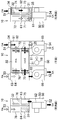
- FIG. 1 is a schematic configuration diagram of a humidity control apparatus according to the first embodiment.
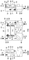
- 2A and 2B are refrigerant circuit diagrams illustrating the schematic configuration of the refrigerant circuit and the operation of the humidifying operation in the first embodiment.
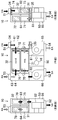
- FIG. 3 is a schematic configuration diagram of the humidity control apparatus showing the first operation of the humidifying operation in the first embodiment.
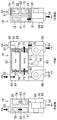
- FIG. 4 is a schematic configuration diagram of the humidity control apparatus showing the second operation of the humidifying operation in the first embodiment.
- 5A and 5B are refrigerant circuit diagrams illustrating a schematic configuration of a refrigerant circuit and an operation of a dehumidifying operation in the first embodiment.
- FIG. 6 is a schematic configuration diagram of the humidity control apparatus showing the first operation of the dehumidifying operation in the first embodiment.
- FIG. 7 is a schematic configuration diagram of a humidity control apparatus showing a second operation of the dehumidifying operation in the first embodiment.
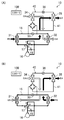
- FIGS. 8A and 8B are refrigerant circuit diagrams illustrating the schematic configuration of the refrigerant circuit and the operation of the humidifying operation in the second embodiment.
- FIGS. 9A and 9B are refrigerant circuit diagrams illustrating the schematic configuration of the refrigerant circuit and the humidifying operation in the third embodiment.
- Embodiment 1 of the Invention The humidity control apparatus (10) of Embodiment 1 supplies dehumidified or humidified air to the room.
- the humidity control apparatus (10) of this embodiment includes a casing (50).
- a refrigerant circuit (15) is accommodated in the casing (50).
- the refrigerant circuit (15) includes a first adsorption heat exchanger (31), a second adsorption heat exchanger (32), a first auxiliary heat exchanger (34), a second auxiliary heat exchanger (35), a compression Machine (16) is provided. Details of the refrigerant circuit (15) will be described later.
- the casing (50) is formed in a flat rectangular parallelepiped shape having a low height.
- an exhaust port (54) is opened at a position on the right side, and an air supply port (52) is opened at a position on the left side.
- an air supply port (52) is opened at a position on the left side.
- the outside air inlet (51) is opened at the right side and the inside air inlet (53) is opened at the left side.
- the internal space of the casing (50) is divided into two parts, the front side and the back side.
- the space on the front side in the casing (50) is further divided into three on the left and right.
- the right side space constitutes the exhaust side flow path (65)
- the left side space constitutes the air supply side flow path (66)
- the central space accommodates the compressor (16) inside.
- the air supply side flow path (66) houses the air supply fan (82) therein and communicates with the room through the air supply port (52).
- the exhaust side flow path (65) houses the exhaust fan (81) and communicates with the outside through the exhaust port (54).
- a second auxiliary heat exchanger (35) is erected in the exhaust side flow path (65). The air flowing into the exhaust side flow path (65) passes through the second auxiliary heat exchanger (35) and is then sucked into the exhaust fan (81).
- the space on the back side in the casing (50) is also divided into three on the left and right.
- the right space is partitioned vertically, the upper space constituting the upper right channel (61) and the lower space constituting the lower right channel (62).
- the upper right channel (61) communicates with the exhaust side channel (65).
- the lower right channel (62) communicates with the outside via the outside air inlet (51).
- a first auxiliary heat exchanger (34) is erected in the lower right channel (62).
- the air flowing into the lower right channel (62) first passes through the first auxiliary heat exchanger (34).
- the left space is divided into upper and lower parts, and the upper space constitutes the upper left channel (63) and the lower space constitutes the lower left channel (64).
- the upper left channel (63) communicates with the air supply side channel (66).
- the lower left channel (64) communicates with the room through the room air inlet (53).
- the central space is partitioned front and back.
- the first adsorption heat exchanger (31) is housed in the front space
- the second adsorption heat exchanger (32) is housed in the rear space, among the central spaces partitioned forward and backward.
- the first adsorption heat exchanger (31) and the second adsorption heat exchanger (32) are installed in a substantially horizontal posture so as to partition the accommodated space vertically.
- the open / close type dampers (71 to 78) are provided on each of the two partition plates that divide the back side of the casing (50) left and right.
- a first upper right damper (71) and a second upper right damper (72) are installed side by side at the upper part, and a first lower right damper (73) and a second lower right damper ( 74) are installed side by side.
- the upper right channel (61) communicates with the space above the first adsorption heat exchanger (31)
- the second upper right damper (72) is opened, the upper right channel (61) Communicates with the space above the second adsorption heat exchanger (32).
- the lower right channel (62) communicates with the space below the first adsorption heat exchanger (31), and when the second lower right damper (74) is opened, the lower right channel (62) communicates with the lower space of the second adsorption heat exchanger (32).
- a first upper left damper (75) and a second upper left damper (76) are arranged side by side on the upper part, and a first lower left damper (77) and a second lower left damper (78) are arranged below the lower part of the partition plate.
- the upper left channel (63) communicates with the space above the first adsorption heat exchanger (31)
- the second upper left damper (76) is opened, the upper left channel (63) Communicates with the space above the second adsorption heat exchanger (32).
- the lower left channel (64) communicates with the lower space of the first adsorption heat exchanger (31), and when the second lower left damper (78) is opened, the lower left channel (64) ) Communicates with the lower space of the second adsorption heat exchanger (32).
- the upper right channel (61), the lower right channel (62), the upper left channel (63), the lower left channel (64), the exhaust side channel (65), And the supply side flow path (66) is formed.
- These flow paths (61 to 66) can switch the air flow path together with the space for storing the first adsorption heat exchanger (31) and the space for storing the second adsorption heat exchanger (32).
- An air passage is formed.
- the refrigerant circuit (15) includes a compressor (16), a first adsorption heat exchanger (31), a second adsorption heat exchanger (32), and an electric expansion valve (33). ) And a four-way selector valve (17).
- An auxiliary circuit (40) is connected in parallel to the electric expansion valve (33) in the refrigerant circuit (15).
- the compressor (16) has a discharge side connected to a first port of the four-way switching valve (17) and a suction side connected to a second port of the four-way switching valve (17).
- the first adsorption heat exchanger (31), the electric expansion valve (33), and the second adsorption are sequentially arranged from the third port to the fourth port of the four-way switching valve (17).
- a heat exchanger (32) is connected in series.
- a communication path provided with an on-off valve (18) is connected between the discharge side and the suction side of the compressor (16).
- the auxiliary circuit (40) is configured as a bridge circuit having a unidirectional passage (41) constituting a unidirectional flow path according to the present invention.
- the bridge circuit four pipe lines each provided with a check valve are connected in a bridge shape, and a pair of opposing connection parts among the four connection parts are connected to the refrigerant circuit (15), while other A pair of connecting portions are connected to one end and the other end of the one-way passage (41), respectively.
- Each of the first adsorption heat exchanger (31), the second adsorption heat exchanger (32), the first auxiliary heat exchanger (34), and the second auxiliary heat exchanger (35) includes a heat transfer tube, a number of fins, It is a cross fin type fin-and-tube heat exchanger composed of In the first and second adsorption heat exchangers (31, 32), an adsorbent is supported on the surface of the fin. In the first and second adsorption heat exchangers (31, 32), the air passing between the fins contacts the adsorbent on the fin surface. Note that zeolite, silica gel, or the like is used as the adsorbent.
- the four-way switching valve (17) includes a first state (state shown in FIG. 2A) in which the first port and the third port communicate with each other and the second port and the fourth port communicate with each other, The mode is switched to the second state (the state shown in FIG. 2B) in which the port and the fourth port communicate with each other and the second port and the third port communicate with each other.
- the humidity control device (10) is a controller that controls the operation of various devices (compressor, electric expansion valve, four-way switching valve, fan, etc.) for constituting the refrigerant circuit (15) and the auxiliary circuit (40). (100).
- a humidifying operation and a dehumidifying operation are performed.
- the air supply fan (82) and the exhaust fan (81) are operated by the controller (100).
- the air supply fan (82) outdoor air is taken into the casing (50) from the outside air inlet (51).
- the exhaust fan (81) room air is taken into the casing (50) from the inside air suction port (53).
- the first operation and the second operation are alternately repeated.
- the first operation during humidification operation will be described.
- a regeneration operation for the first adsorption heat exchanger (31) and an adsorption operation for the second adsorption heat exchanger (32) are performed.
- the four-way switching valve (17) is set to the first state by the controller (100), and the electric expansion valve (33) and the electric motor
- the opening degree of the expansion valve (36) is adjusted as appropriate.
- the refrigerant discharged from the compressor (16) flows into the first adsorption heat exchanger (31), and dissipates heat to the outdoor air and condenses in the first adsorption heat exchanger (31). To do.
- Part of the condensed refrigerant flows into the auxiliary circuit (40) connected in parallel to the electric expansion valve (33), and the rest flows into the electric expansion valve (33). Depressurized.
- the auxiliary circuit (40) is configured as a bridge circuit. Therefore, the refrigerant flowing into the auxiliary circuit (40) always flows in one direction through the one-way passage (41) of the bridge circuit. Specifically, the refrigerant flowing into the first auxiliary heat exchanger (34) dissipates heat to the outdoor air, condenses, and is decompressed when passing through the electric expansion valve (36). The decompressed refrigerant flows into the second auxiliary heat exchanger (35), absorbs heat from the room air, and evaporates. The evaporated refrigerant joins the refrigerant decompressed by the electric expansion valve (33) in the refrigerant circuit (15).
- the merged refrigerant flows into the second adsorption heat exchanger (32) and absorbs heat from the room air to evaporate.
- the evaporated refrigerant is sucked into the compressor (16) and compressed.
- the first adsorption heat exchanger (31) and the first auxiliary heat exchanger (34) serve as a condenser
- the second adsorption heat exchanger (32) and The second auxiliary heat exchanger (35) serves as an evaporator.
- the first lower right damper (73) and the second upper right damper (72) are in the open state, and the first upper right damper (71) and the second lower right damper are in the open state. (74) is closed. Further, the first upper left damper (75) and the second lower left damper (78) are opened, and the first lower left damper (77) and the second upper left damper (76) are closed.
- the second adsorption heat exchanger (32) moisture in the room air is adsorbed by the adsorbent to dehumidify the room air, and the heat of adsorption generated at that time is absorbed by the refrigerant.
- the room air that has flowed into the exhaust side flow path (65) exchanges heat with the refrigerant when passing through the second auxiliary heat exchanger (35), and radiates heat to the refrigerant. Thereafter, the room air is discharged from the exhaust port (54) to the outside of the room.
- the outdoor air flows through the first lower right damper (73) to the lower side of the first adsorption heat exchanger (31), and moves from the bottom to the first adsorption heat exchanger (31). Pass through.
- the first adsorption heat exchanger (31) moisture is desorbed from the adsorbent heated by the refrigerant, and the desorbed moisture is given to the outdoor air.
- the outdoor air humidified by the first adsorption heat exchanger (31) flows into the upper left flow path (63) through the first upper left damper (75), and is supplied after passing through the supply side flow path (66). It is supplied into the room from the mouth (52).
- the second operation during humidification operation will be described.
- an adsorption operation for the first adsorption heat exchanger (31) and a regeneration operation for the second adsorption heat exchanger (32) are performed.
- the four-way selector valve (17) is set to the second state by the controller (100), and the electric expansion valve (33) and the electric motor
- the opening degree of the expansion valve (36) is adjusted as appropriate.
- the refrigerant discharged from the compressor (16) flows into the second adsorption heat exchanger (32), dissipates heat to the outdoor air, and condenses.
- Part of the condensed refrigerant flows into the auxiliary circuit (40) connected in parallel to the electric expansion valve (33), and the rest flows into the electric expansion valve (33). Depressurized.
- the auxiliary circuit (40) is configured as a bridge circuit. Therefore, the refrigerant flowing into the auxiliary circuit (40) always flows in one direction through the one-way passage (41) of the bridge circuit. Specifically, the refrigerant flowing into the first auxiliary heat exchanger (34) dissipates heat to the outdoor air, condenses, and is decompressed when passing through the electric expansion valve (36). The decompressed refrigerant flows into the second auxiliary heat exchanger (35), absorbs heat from the room air, and evaporates. The evaporated refrigerant joins the refrigerant decompressed by the electric expansion valve (33) in the refrigerant circuit (15).
- the merged refrigerant flows into the first adsorption heat exchanger (31), absorbs heat from the room air, and evaporates.
- the evaporated refrigerant is sucked into the compressor (16) and compressed.
- the second adsorption heat exchanger (32) and the first auxiliary heat exchanger (34) serve as a condenser, and the first adsorption heat exchanger (31) and The second auxiliary heat exchanger (35) serves as an evaporator.
- the first upper right damper (71) and the second lower right damper (74) are opened, and the first lower right damper (73) and the second upper right damper are opened. (72) is closed. Further, the first lower left damper (77) and the second upper left damper (76) are opened, and the first upper left damper (75) and the second lower left damper (78) are closed.
- the first adsorption heat exchanger (31) moisture in the room air is adsorbed by the adsorbent to dehumidify the room air, and the heat of adsorption generated at that time is absorbed by the refrigerant.
- the room air that has flowed into the exhaust side flow path (65) exchanges heat with the refrigerant when passing through the second auxiliary heat exchanger (35), and radiates heat to the refrigerant. Thereafter, the room air is discharged from the exhaust port (54) to the outside of the room.
- the outdoor air flows through the second lower right damper (74) to the lower side of the second adsorption heat exchanger (32), and moves from the bottom to the second adsorption heat exchanger (32). Pass through.
- the second adsorption heat exchanger (32) moisture is desorbed from the adsorbent heated by the refrigerant, and the desorbed moisture is given to the outdoor air.
- the outdoor air humidified by the second adsorption heat exchanger (32) flows into the upper left channel (63) through the second upper left damper (76), and is supplied after passing through the supply side channel (66). It is supplied into the room from the mouth (52).
- the first adsorption heat exchanger (31) serves as a moisture removal adsorption heat exchanger that functions as a condenser.
- the second adsorption is performed.
- the heat exchanger (32) serves as a moisture adsorption heat exchanger that functions as a condenser.
- the first auxiliary heat exchanger (34) serves as a condenser
- the second auxiliary heat exchanger (35) serves as an evaporator.
- the first auxiliary heat exchanger (34) serving as a condenser is upstream of the first adsorption heat exchanger (31) serving as a dehumidifying adsorption heat exchanger for outdoor air flow.
- the first auxiliary heat exchanger (34) serving as a condenser is disposed upstream of the second adsorption heat exchanger (32) serving as a dehumidifying adsorption heat exchanger for outdoor air flow. Will be located.
- the first auxiliary heat exchanger (34) is located upstream of the dehumidifying adsorption heat exchanger in the flow of outdoor air in the air passage during the humidifying operation, and functions as a condenser to heat the outdoor air. It becomes a preheating heat exchanger.
- the outdoor air preheated by the preheating heat exchanger is supplied to the dehumidifying adsorption heat exchanger, is humidified by the dehumidifying adsorption heat exchanger, and is supplied indoors.
- outdoor air first exchanges heat with the refrigerant when passing through the preheating heat exchanger and absorbs heat from the refrigerant. Thereby, the relative humidity of outdoor air falls.
- the outdoor air passes through the moisture-absorbing adsorption heat exchanger.
- moisture desorption adsorption heat exchanger moisture is desorbed from the adsorbent heated by the refrigerant, and the desorbed moisture is given to the outdoor air.
- the outdoor air passing through the dehumidifying adsorption heat exchanger is preheated in the preheating heat exchanger and the relative humidity is lowered, so that it is desorbed from the adsorbent of the dehumidifying adsorption heat exchanger. Therefore, much of the desorbed moisture is contained in the outdoor air. Therefore, the indoor air is sufficiently humidified by supplying outdoor air to which moisture has been sufficiently imparted in the dehumidifying adsorption heat exchanger.
- the second auxiliary heat exchanger (35) serving as an evaporator is disposed downstream of the second auxiliary heat exchanger (35) serving as a moisture absorption heat exchanger for indoor air flow.
- the second auxiliary heat exchanger (35) serving as an evaporator is located downstream of the first adsorption heat exchanger (31) serving as a hygroscopic adsorption heat exchanger for the flow of room air. It will be. That is, the second auxiliary heat exchanger (35) is located downstream of the hygroscopic adsorption heat exchanger of the flow of room air in the air passage during the humidifying operation, and functions as an evaporator to heat the room air.
- the room air dehumidified by the moisture absorption heat exchanger is supplied to the heat recovery heat exchanger, and the refrigerant is absorbed by the refrigerant in the heat recovery heat exchanger and supplied to the room.
- the room air first passes through the hygroscopic adsorption heat exchanger. At this time, moisture in the room air is adsorbed by the adsorbent, and the room air is dehumidified. Then, the heat of adsorption generated at that time is absorbed by the refrigerant.
- the room air deprived of moisture by the moisture absorption heat exchanger exchanges heat with the refrigerant when passing through the heat recovery heat exchanger (and dissipates heat to the refrigerant, and is then discharged outside the room.
- ⁇ Dehumidifying operation> In the humidity control apparatus (10) during the dehumidifying operation, the air supply fan (82) and the exhaust fan (81) are operated by the controller (100). When the air supply fan (82) is operated, outdoor air is taken into the casing (50) from the outside air inlet (51). When the exhaust fan (81) is operated, room air is taken into the casing (50) from the inside air suction port (53). In the humidity control apparatus (10) during the dehumidifying operation, the first operation and the second operation are alternately repeated.
- the first operation during dehumidifying operation will be described.
- a regeneration operation for the first adsorption heat exchanger (31) and an adsorption operation for the second adsorption heat exchanger (32) are performed.
- the four-way selector valve (17) is set to the first state by the controller (100), and the electric expansion valve (36) is predetermined. And the opening degree of the electric expansion valve (33) is appropriately adjusted.
- the refrigerant discharged from the compressor (16) flows into the first adsorption heat exchanger (31) and radiates and condenses to the indoor air in the first adsorption heat exchanger (31). To do.
- the condensed refrigerant flows into the electric expansion valve (33) and is decompressed by the electric expansion valve (33).
- the decompressed refrigerant flows into the second adsorption heat exchanger (32), and evaporates by absorbing heat from outdoor air in the second adsorption heat exchanger (32).
- the evaporated refrigerant is sucked into the compressor (16) and compressed.
- the electric expansion valve (36) is set to a predetermined minimum opening, the refrigerant condensed in the first adsorption heat exchanger (31) hardly flows into the auxiliary circuit (40). However, a small amount of refrigerant flows into the auxiliary circuit (40).
- the first upper right damper (71) and the second lower right damper (74) are opened, and the first lower right damper (73) and the second upper right damper (74) are opened.
- the damper (72) is closed.
- the first lower left damper (77) and the second upper left damper (76) are opened, and the first upper left damper (75) and the second lower left damper (78) are closed.
- the outdoor air flowing into the lower right channel (62) from the outside air inlet (51) passes through the first auxiliary heat exchanger (34) and then passes through the second lower right damper (74) to perform the second adsorption heat exchange. It flows into the lower side of the vessel (32) and passes through the second adsorption heat exchanger (32) from the bottom to the top.
- the second adsorption heat exchanger (32) moisture in the outdoor air is adsorbed by the adsorbent to dehumidify the outdoor air, and the heat of adsorption generated at that time is absorbed by the refrigerant.
- the outdoor air dehumidified by the second adsorption heat exchanger (32) flows into the upper left channel (63) through the second upper left damper (76), and is supplied after passing through the supply side channel (66). It is supplied into the room from the mouth (52).
- the refrigerant hardly flows into the first auxiliary heat exchanger (34). Therefore, when the outdoor air passes through the first auxiliary heat exchanger (34), the outdoor air hardly exchanges heat with the refrigerant.
- the first adsorption heat exchanger (31) moisture is desorbed from the adsorbent heated by the refrigerant, and the desorbed moisture is given to the room air.
- the second operation during the dehumidifying operation will be described.
- an adsorption operation for the first adsorption heat exchanger (31) and a regeneration operation for the second adsorption heat exchanger (32) are performed.
- the controller (100) sets the four-way switching valve (17) to the second state, and the electric expansion valve (36) is predetermined. And the opening degree of the electric expansion valve (33) is appropriately adjusted.
- the refrigerant discharged from the compressor (16) flows into the second adsorption heat exchanger (32) and radiates and condenses to room air in the second adsorption heat exchanger (32). To do.
- the condensed refrigerant flows into the electric expansion valve (33) and is decompressed by the electric expansion valve (33).
- the decompressed refrigerant flows into the first adsorption heat exchanger (31), evaporates by absorbing heat from outdoor air in the first adsorption heat exchanger (31). The evaporated refrigerant is sucked into the compressor (16) and compressed.
- the electric expansion valve (36) is set to a predetermined minimum opening, the refrigerant condensed in the second adsorption heat exchanger (32) hardly flows into the auxiliary circuit (40). However, a small amount of refrigerant flows into the auxiliary circuit (40).
- the first lower right damper (73) and the second upper right damper (72) are opened, and the first upper right damper (71) and the second lower right damper are opened.
- the damper (74) is closed.
- the first upper left damper (75) and the second lower left damper (78) are opened, and the first lower left damper (77) and the second upper left damper (76) are closed.
- the outdoor air flowing into the lower right channel (62) from the outside air inlet (51) passes through the first auxiliary heat exchanger (34) and then passes through the first lower right damper (73) to perform the first adsorption heat exchange. It flows into the lower side of the vessel (31) and passes through the first adsorption heat exchanger (31) from the bottom to the top.
- the first adsorption heat exchanger (31) moisture in the outdoor air is adsorbed by the adsorbent and the outdoor air is dehumidified, and the adsorption heat generated at that time is absorbed by the refrigerant.
- the outdoor air dehumidified by the first adsorption heat exchanger (31) flows into the upper left channel (63) through the first upper left damper (75), and is supplied after passing through the supply side channel (66). It is supplied into the room from the mouth (52).
- the refrigerant hardly flows into the first auxiliary heat exchanger (34). Therefore, when the outdoor air passes through the first auxiliary heat exchanger (34), the outdoor air hardly exchanges heat with the refrigerant.
- the second adsorption heat exchanger (32) moisture is desorbed from the adsorbent heated by the refrigerant, and the desorbed moisture is given to the room air.
- the humidity control apparatus (10) in the humidity control apparatus (10) during the humidifying operation, the outdoor air is heated by the first auxiliary heat exchanger (34) serving as a preheating heat exchanger, and then the first and second The moisture absorption adsorption heat exchanger of the second adsorption heat exchanger (31, 32) was allowed to pass through. Therefore, most of the moisture desorbed from the adsorbent of the moisture-absorbing adsorption heat exchanger can be included in the outdoor air even at a low outdoor temperature. Therefore, the room can be sufficiently humidified.
- the room air is dehumidified by the hygroscopic adsorption heat exchanger of the first and second adsorption heat exchangers (31, 32) and then becomes a heat recovery heat exchanger.
- the second auxiliary heat exchanger (35) was passed through. Therefore, moisture in the room air does not condense in the second auxiliary heat exchanger (35), and the refrigerant absorbs heat sufficiently from the room air while sufficiently collecting moisture in the room air in the hygroscopic adsorption heat exchanger. It can be recovered. Therefore, according to the above configuration, the room can be sufficiently humidified even at a low outside air temperature.
- humidification operation is used together with heating mainly in winter.
- the temperature of the outdoor air after humidification supplied to the room becomes lower than the room temperature. May increase the heating load in the room.
- the humidity control apparatus (10) outdoor air can be heated to some extent in the first auxiliary heat exchanger (34) serving as a preheating heat exchanger.
- the refrigerant recovers heat from the indoor air not only in the moisture absorption heat exchanger but also in the second auxiliary heat exchanger (35) serving as a heat recovery heat exchanger.
- the amount of heat released from the refrigerant in the moisture-absorbing adsorption heat exchanger and the first auxiliary heat exchanger (34) increases. Therefore, according to the humidity control apparatus (10), even during the humidification operation at a low outdoor temperature, it is possible to sufficiently secure the heat radiation amount of the refrigerant with respect to the outdoor air. Can be suppressed.
- the refrigerant circuit includes a first auxiliary heat exchanger (34) that serves as a preheating heat exchanger, an expansion valve (36), and a second auxiliary heat exchanger that serves as a heat recovery heat exchanger.
- An auxiliary circuit (40) is connected in series with (35).
- the one-way passage (41) of the auxiliary circuit (40) is provided with a first auxiliary heat exchanger (34) serving as a preheating heat exchanger, an expansion valve (36), and heat recovery heat.
- a second auxiliary heat exchanger (35) serving as an exchanger is provided. Therefore, even if the refrigerant circulation direction of the refrigerant circuit (15) is reversed, the refrigerant flows in one direction in the one-way passage (41), so that the first auxiliary heat exchanger (34) and the second auxiliary heat exchanger (35) does not switch between the preheating heat exchanger and the heat recovery heat exchanger, the first auxiliary heat exchanger (34) is always the preheating heat exchanger, and the second auxiliary heat exchanger (35) is the heat.
- the auxiliary circuit (40) having the one-way passage (41) through which the refrigerant flows in one direction even when the refrigerant circulation direction in the refrigerant circuit (15) is reversed is provided by the bridge circuit.
- the auxiliary circuit (40) can be easily configured.
- the expansion valve (36) of the auxiliary circuit (40) is opened to a predetermined minimum opening so that the refrigerant flows in the auxiliary circuit (40) slightly.
- the accumulation of refrigerant in the first auxiliary heat exchanger (34) can be suppressed. Therefore, it is possible to suppress a decrease in efficiency of the refrigeration cycle due to a decrease in the refrigerant circulation amount in the refrigerant circuit (15).
- Embodiment 2 of the Invention The humidity control apparatus (10) of the second embodiment is obtained by changing the circuit configuration of the humidity control apparatus (10) of the first embodiment.
- the auxiliary circuit (40) is configured by a bypass passage (42) that connects the discharge side and the suction side of the compressor (16).
- the bypass passage (42) has one end connected to a middle portion of the discharge pipe connecting the discharge side of the compressor (16) and the first port of the four-way switching valve (17), and the other end.
- the suction pipe is connected to the suction pipe connecting the suction side of the compressor (16) and the second port of the four-way switching valve (17).
- a first auxiliary heat exchanger (34), an expansion valve (36), and a second auxiliary heat exchanger (35) are sequentially arranged from the discharge side to the suction side of the compressor (16). Connected in series.
- the four-way switching valve (17) is switched and the refrigerant circulation direction in the refrigerant circuit (15) is changed. Even if it is changed, it constitutes a one-way flow path in which the refrigerant flows in one direction.
- the first auxiliary heat exchanger (34) is always a condenser
- the second auxiliary heat exchanger (35) is an evaporator.
- the controller (100) sets the four-way switching valve (17) to the first state, and the electric expansion valve (33) of the refrigerant circuit (15). ) And the opening degree of the electric expansion valve (36) of the auxiliary circuit (40) is appropriately adjusted.
- the refrigerant discharged from the compressor (16) partially flows into the bypass passage (42) of the auxiliary circuit (40) connected to the discharge pipe, and the rest is the four-way switching valve ( It passes through 17) and flows to the first adsorption heat exchanger (31) side.
- the bypass passage (42) the refrigerant passes through the first auxiliary heat exchanger (34), the electric expansion valve (36), and the second auxiliary heat exchanger (35) in this order.
- the refrigerant that has radiated and condensed the outdoor air in the first auxiliary heat exchanger (34) is depressurized by the electric expansion valve (36), then absorbs heat from the indoor air in the second auxiliary heat exchanger (35) and evaporates. To do.
- the evaporated refrigerant flows into the suction pipe of the compressor (16) of the refrigerant circuit (15).
- the refrigerant passes through the first adsorption heat exchanger (31), the electric expansion valve (33), and the second adsorption heat exchanger (32) in this order.
- the refrigerant that has radiated and condensed the outdoor air in the first adsorption heat exchanger (31) is depressurized in the electric expansion valve (33), and then absorbs heat from the indoor air in the second adsorption heat exchanger (32) and evaporates.
- the evaporated refrigerant merges with the refrigerant from the bypass passage (42) in the suction pipe of the compressor (16), and is sucked into the compressor (16) and compressed.
- the indoor air taken in from the room is converted into the second adsorption heat exchanger (32) and the second auxiliary heat exchanger (35).
- the room air is dehumidified by the moisture in the room air being adsorbed by the adsorbent in the second adsorption heat exchanger (32), and the heat of adsorption generated at that time is absorbed by the refrigerant.
- the room air dehumidified by the second adsorption heat exchanger (32) is absorbed by the refrigerant when passing through the second auxiliary heat exchanger (35), and then discharged outside the room.
- outdoor air taken in from the outside passes through the first auxiliary heat exchanger (34) and the first adsorption heat exchanger (31) in this order and is supplied to the room.
- the outdoor air is heated by the refrigerant when passing through the first auxiliary heat exchanger (34)
- the outdoor air is heated by the refrigerant in the first adsorption heat exchanger (31) and is given moisture desorbed from the adsorbent. Humidified and then supplied indoors.
- the controller (100) sets the four-way switching valve (17) to the second state, and the electric expansion valve (33) of the refrigerant circuit (15). ) And the opening degree of the electric expansion valve (36) of the auxiliary circuit (40) is appropriately adjusted.
- the refrigerant discharged from the compressor (16) partially flows into the bypass passage (42) of the auxiliary circuit (40) connected to the discharge pipe, and the rest is the four-way switching valve ( It passes through 17) and flows to the second adsorption heat exchanger (32) side.
- the bypass passage (42) the refrigerant passes through the first auxiliary heat exchanger (34), the electric expansion valve (36), and the second auxiliary heat exchanger (35) in this order.
- the refrigerant that has radiated and condensed the outdoor air in the first auxiliary heat exchanger (34) is depressurized by the electric expansion valve (36), then absorbs heat from the indoor air in the second auxiliary heat exchanger (35) and evaporates. To do.
- the evaporated refrigerant flows into the suction pipe of the compressor (16) of the refrigerant circuit (15).
- the refrigerant passes through the second adsorption heat exchanger (32), the electric expansion valve (33), and the first adsorption heat exchanger (31) in this order.
- the refrigerant that has radiated and condensed the outdoor air in the second adsorption heat exchanger (32) is depressurized in the electric expansion valve (33), and then absorbs heat from the indoor air in the first adsorption heat exchanger (31) and evaporates.
- the evaporated refrigerant merges with the refrigerant from the bypass passage (42) in the suction pipe of the compressor (16), and is sucked into the compressor (16) and compressed.
- the indoor air taken in from the room is converted into the first adsorption heat exchanger (31) and the second auxiliary heat exchanger (35).
- the room air is dehumidified in the first adsorption heat exchanger (31) by the moisture in the room air being adsorbed by the adsorbent, and the heat of adsorption generated at that time is absorbed by the refrigerant.
- the room air dehumidified by the first adsorption heat exchanger (31) is absorbed by the refrigerant when passing through the second auxiliary heat exchanger (35), and then discharged outside the room.
- outdoor air taken in from the outside passes through the first auxiliary heat exchanger (34) and the second adsorption heat exchanger (32) in this order and is supplied to the room.
- the outdoor air is heated by the refrigerant when passing through the first auxiliary heat exchanger (34), and then is heated by the refrigerant in the second adsorption heat exchanger (32) and is given moisture desorbed from the adsorbent. Humidified and then supplied indoors.
- the operation of the humidity control apparatus (10) during the dehumidifying operation is performed by setting the electric expansion valve (36) to a predetermined minimum opening so that only a small amount of refrigerant flows into the auxiliary circuit (40).
- the operation is the same as the operation during the humidifying operation except that the air flow in the operation and the second operation is reversed to supply the dehumidified outdoor air to the room and the humidified indoor air is discharged to the outside.
- the first adsorption heat exchanger (31) serves as a moisture removal adsorption heat exchanger that functions as a condenser
- the second adsorption is performed.
- the heat exchanger (32) serves as a moisture adsorption heat exchanger that functions as a condenser.
- the first auxiliary heat exchanger (34) serves as a condenser
- the second auxiliary heat exchanger (35) serves as an evaporator.
- the first auxiliary heat exchanger (34) serving as a condenser is upstream of the first adsorption heat exchanger (31) serving as a dehumidifying adsorption heat exchanger for outdoor air flow.
- the first auxiliary heat exchanger (34) serving as a condenser is disposed upstream of the second adsorption heat exchanger (32) serving as a dehumidifying adsorption heat exchanger for outdoor air flow. Will be located.
- the first auxiliary heat exchanger (34) is located upstream of the dehumidifying adsorption heat exchanger in the flow of outdoor air in the air passage during the humidifying operation, and functions as a condenser to heat the outdoor air. It becomes a preheating heat exchanger.
- the outdoor air preheated by the first auxiliary heat exchanger (34) is supplied to the dehumidifying adsorption heat exchanger, is humidified by the dehumidifying adsorption heat exchanger, and is supplied to the room.
- the second auxiliary heat exchanger (35) serving as an evaporator is disposed downstream of the second auxiliary heat exchanger (35) serving as a moisture absorption heat exchanger for indoor air flow.
- the second auxiliary heat exchanger (35) serving as an evaporator is located downstream of the first adsorption heat exchanger (31) serving as a hygroscopic adsorption heat exchanger for the flow of room air. It will be. That is, the second auxiliary heat exchanger (35) is located downstream of the hygroscopic adsorption heat exchanger of the flow of room air in the air passage during the humidifying operation, and functions as an evaporator to heat the room air.
- the room air dehumidified by the moisture absorption heat exchanger is supplied to the second auxiliary heat exchanger, and is absorbed by the refrigerant in the second auxiliary heat exchanger and supplied to the room.
- Embodiment 3 of the Invention The humidity control apparatus (10) of the third embodiment is obtained by changing the circuit configuration and the air passage of the humidity control apparatus (10) of the first embodiment.
- the auxiliary circuit (40) is connected to each of the first adsorption heat exchanger (31) and the second adsorption heat exchanger (32). It is constituted by a bypass passage (43) for connecting the gas pipes.
- the bypass passage (43) has one end connected to the middle part of the gas pipe connecting the first adsorption heat exchanger (31) and the third port of the four-way switching valve (17), and the other end. Is connected to the middle part of the suction pipe connecting the second adsorption heat exchanger (32) and the fourth port of the four-way switching valve (17).
- the bypass passage (43) includes a first auxiliary heat exchanger (34), an expansion valve (36), and a second auxiliary heat exchanger from the third port side to the fourth port side of the four-way switching valve (17). (35) are connected in series.
- the refrigerant flow direction is reversed according to the refrigerant circulation direction in the refrigerant circuit (15).
- the first auxiliary heat exchanger (34) becomes a condenser and the second auxiliary heat exchanger (35) becomes an evaporator.
- the second auxiliary heat exchanger (35) becomes a condenser, and the first auxiliary heat exchanger (34) becomes an evaporator.
- the controller (100) sets the four-way switching valve (17) to the first state, and the electric expansion valve (33) of the refrigerant circuit (15). ) And the opening degree of the electric expansion valve (36) of the auxiliary circuit (40) is appropriately adjusted.
- the refrigerant discharged from the compressor (16) passes through the four-way switching valve (17) and flows to the first adsorption heat exchanger (31) side, and a part thereof is the auxiliary circuit (40 ) And the remainder flow into the first adsorption heat exchanger (31).
- the refrigerant passes through the first auxiliary heat exchanger (34), the electric expansion valve (36), and the second auxiliary heat exchanger (35) in this order.
- the refrigerant that has radiated and condensed the outdoor air in the first auxiliary heat exchanger (34) is depressurized by the electric expansion valve (36), then absorbs heat from the indoor air in the second auxiliary heat exchanger (35) and evaporates. To do.
- the evaporated refrigerant flows into the gas pipe connected to the second adsorption heat exchanger (32) of the refrigerant circuit (15).
- the refrigerant passes through the first adsorption heat exchanger (31), the electric expansion valve (33), and the second adsorption heat exchanger (32) in this order.
- the refrigerant that has radiated and condensed the outdoor air in the first adsorption heat exchanger (31) is depressurized in the electric expansion valve (33), and then absorbs heat from the indoor air in the second adsorption heat exchanger (32) and evaporates. To do.
- the evaporated refrigerant merges with the refrigerant from the bypass passage (43), and is sucked into the compressor (16) and compressed.
- Embodiment 3 when the refrigerant flows in the refrigerant circuit (15) and the auxiliary circuit (40), an air passage is formed so that air flows as follows.
- the indoor air taken in from the room passes through the second adsorption heat exchanger (32) and the second auxiliary heat exchanger (35) in this order and is discharged outside the room.
- the room air is dehumidified by the moisture in the room air being adsorbed by the adsorbent in the second adsorption heat exchanger (32), and the heat of adsorption generated at that time is absorbed by the refrigerant.
- the room air dehumidified by the second adsorption heat exchanger (32) is absorbed by the refrigerant when passing through the second auxiliary heat exchanger (35), and then discharged outside the room.
- outdoor air taken in from the outside passes through the first auxiliary heat exchanger (34) and the first adsorption heat exchanger (31) in this order and is supplied to the room.
- the outdoor air is heated by the refrigerant when passing through the first auxiliary heat exchanger (34)
- the outdoor air is heated by the refrigerant in the first adsorption heat exchanger (31) and is given moisture desorbed from the adsorbent. Humidified and then supplied indoors.
- the controller (100) sets the four-way switching valve (17) to the second state, and the electric expansion valve (33) of the refrigerant circuit (15). ) And the opening degree of the electric expansion valve (36) of the auxiliary circuit (40) is appropriately adjusted.
- the refrigerant discharged from the compressor (16) passes through the four-way switching valve (17) and flows to the second adsorption heat exchanger (32) side, and a part thereof is the auxiliary circuit (40 ) And the rest flow into the second adsorption heat exchanger (32).
- the refrigerant passes through the second auxiliary heat exchanger (35), the electric expansion valve (36), and the first auxiliary heat exchanger (34) in this order.
- the refrigerant that has radiated and condensed the outdoor air in the second auxiliary heat exchanger (35) is depressurized by the electric expansion valve (36), and then absorbs heat from the indoor air in the first auxiliary heat exchanger (34) and evaporates. To do.
- the evaporated refrigerant flows into the gas pipe connected to the first adsorption heat exchanger (31) of the refrigerant circuit (15).
- the refrigerant passes through the second adsorption heat exchanger (32), the electric expansion valve (33), and the first adsorption heat exchanger (31) in this order.
- the refrigerant that has radiated and condensed the outdoor air in the second adsorption heat exchanger (32) is depressurized in the electric expansion valve (33), and then absorbs heat from the indoor air in the first adsorption heat exchanger (31) and evaporates. To do.
- the evaporated refrigerant merges with the refrigerant from the bypass passage (43), and is sucked into the compressor (16) and compressed.
- the air passage of the third embodiment is formed so that air flows as follows when the refrigerant flows in the refrigerant circuit (15) and the auxiliary circuit (40) as described above.
- the indoor air taken in from the room passes through the first adsorption heat exchanger (31) and the first auxiliary heat exchanger (34) in this order and is discharged outside the room.
- the room air is dehumidified in the first adsorption heat exchanger (31) by the moisture in the room air being adsorbed by the adsorbent, and the heat of adsorption generated at that time is absorbed by the refrigerant.
- the room air dehumidified by the first adsorption heat exchanger (31) is absorbed by the refrigerant when passing through the first auxiliary heat exchanger (34), and then discharged outside the room.
- outdoor air taken in from the outside passes through the second auxiliary heat exchanger (35) and the second adsorption heat exchanger (32) in this order and is supplied to the room.
- the outdoor air is heated by the refrigerant when passing through the second auxiliary heat exchanger (35), and is then heated by the refrigerant in the second adsorption heat exchanger (32) and is given moisture desorbed from the adsorbent. Humidified and then supplied indoors.
- the operation of the humidity control apparatus (10) during the dehumidifying operation is performed by setting the electric expansion valve (36) to a predetermined minimum opening so that only a small amount of refrigerant flows into the auxiliary circuit (40).
- the operation is the same as the operation during the humidifying operation except that the air flow in the second operation is reversed to supply the dehumidified outdoor air to the room and the humidified indoor air is discharged to the outside.
- the first adsorption heat exchanger (31) serves as a moisture removal adsorption heat exchanger that functions as a condenser
- the second adsorption is performed.
- the heat exchanger (32) serves as a moisture adsorption heat exchanger that functions as a condenser.
- the first auxiliary heat exchanger (34) serves as a condenser
- the second auxiliary heat exchanger (35) serves as an evaporator.
- the second auxiliary heat exchanger (35) serves as a condenser
- the first auxiliary heat exchanger (34) serves as an evaporator.
- the first auxiliary heat exchanger (34) serving as a condenser is upstream of the first adsorption heat exchanger (31) serving as a dehumidifying adsorption heat exchanger for outdoor air flow.
- the second auxiliary heat exchanger (35) serving as a condenser is disposed upstream of the second adsorption heat exchanger (32) serving as a dehumidifying adsorption heat exchanger for outdoor air flow.
- the first auxiliary heat exchanger (34) serves as a preheating heat exchanger during the first operation during the humidifying operation
- the second auxiliary heat exchanger (35) serves as the preheating heat exchanger during the second operation. It becomes.
- the outdoor air preheated by the preheating heat exchanger is supplied to the dehumidifying adsorption heat exchanger, is humidified by the dehumidifying adsorption heat exchanger, and is supplied indoors.
- the Rukoto is also supplied outdoors.
- the second auxiliary heat exchanger (35) serving as an evaporator is disposed downstream of the second auxiliary heat exchanger (35) serving as a moisture absorption heat exchanger for indoor air flow.
- the first adsorption heat exchanger (31) serving as an evaporator is located downstream of the second auxiliary heat exchanger (35) serving as a moisture absorption adsorption heat exchanger for the flow of indoor air.
- the second auxiliary heat exchanger (35) serves as a heat recovery heat exchanger during the first operation during the humidifying operation
- the first auxiliary heat exchanger (34) serves as the heat recovery heat during the second operation. It becomes an exchanger.
- the room air dehumidified by the moisture absorption heat exchanger is supplied to the heat recovery heat exchanger, and the refrigerant is absorbed by the refrigerant in the heat recovery heat exchanger and supplied to the room.
- a material that mainly adsorbs water vapor such as silica gel or zeolite
- a material that adsorbs and absorbs water vapor may be used as the adsorbent.
- an organic polymer material having hygroscopicity can be used as the adsorbent.
- a plurality of polymer main chains having hydrophilic polar groups in the molecule are cross-linked with each other, and the plurality of polymer main chains cross-linked with each other form a three-dimensional structure. Forming.
- Such adsorbents swell by trapping (ie, absorbing moisture) water vapor.
- the mechanism by which the adsorbent swells by absorbing moisture is presumed as follows.
- this adsorbent absorbs moisture
- water vapor is adsorbed around the hydrophilic polar group, and the electric force generated by the reaction between the hydrophilic polar group and water vapor acts on the polymer main chain.
- the polymer main chain is deformed.
- water vapor is taken into the gap between the deformed polymer main chains by capillary force, and when the water vapor enters, a three-dimensional structure composed of a plurality of polymer main chains swells, resulting in an increase in the volume of the adsorbent. .
- both the phenomenon that water vapor is adsorbed by the adsorbent and the phenomenon that water vapor is absorbed by the adsorbent occur. That is, water vapor is sorbed on the adsorbent. Further, the water vapor captured by the adsorbent enters not only the surface of the three-dimensional structure composed of a plurality of polymer main chains cross-linked with each other but also into the interior thereof. As a result, a large amount of water vapor is trapped in this adsorbent as compared with zeolite that only adsorbs water vapor on the surface.
- the adsorbent shrinks by releasing water vapor (that is, moisture release).
- water vapor that is, moisture release.
- the material used as the adsorbent is not limited to the above-described material as long as it swells by absorbing moisture and contracts by releasing moisture.
- an ion-exchange resin having hygroscopicity may be used. Good.
- the present invention is useful for a humidity control apparatus that adjusts indoor humidity using an adsorbent.
Landscapes
- Engineering & Computer Science (AREA)
- Chemical & Material Sciences (AREA)
- Mechanical Engineering (AREA)
- General Engineering & Computer Science (AREA)
- Combustion & Propulsion (AREA)
- Thermal Sciences (AREA)
- Physics & Mathematics (AREA)
- Analytical Chemistry (AREA)
- General Chemical & Material Sciences (AREA)
- Oil, Petroleum & Natural Gas (AREA)
- Chemical Kinetics & Catalysis (AREA)
- Central Air Conditioning (AREA)
- Compression-Type Refrigeration Machines With Reversible Cycles (AREA)
- Drying Of Gases (AREA)
Abstract
調湿装置(10)は、室外空気が凝縮器となる放湿吸着熱交換器を通過して室内に供給され、室内空気が蒸発器となる吸湿吸着熱交換器を通過して室外に排出される加湿運転を行う。この調湿装置(10)に、加湿運転の際に、空気通路における室外空気の流れの放湿吸着熱交換器の上流側に位置し且つ冷媒回路(15)において凝縮器として機能して室外空気を加熱する予熱熱交換器(34)と、加湿運転の際に、空気通路における室内空気の流れの吸湿吸着熱交換器の下流側に位置し且つ冷媒回路(15)において蒸発器として機能して室内空気の熱を回収する熱回収熱交換器(35)とを設ける。
Description
本発明は、吸着剤を用いて室内の湿度を調節する調湿装置に関するものである。
従来から、吸着剤を用いて室内の湿度を調節する調湿装置が知られている。特許文献1には、この種の調湿装置として、吸着剤が担持された2つの吸着熱交換器を用いて室内の湿度を調節するものが開示されている。
上記調湿装置では、圧縮機と膨張機構と2つの吸着熱交換器が接続されて冷媒循環方向が可逆に構成された冷媒回路と、室内空気及び室外空気の一方の空気が上記2つの吸着熱交換器のうちの凝縮器として機能する放湿吸着熱交換器を通過し、他方の空気が蒸発器として機能する吸湿吸着熱交換器を通過するように冷媒回路での冷媒循環方向に応じて空気の流通経路が切り換わるように構成された空気通路とを備えている。そして、上記調湿装置では、室外空気が放湿吸着熱交換器を通過して室内に供給される一方、室内空気が吸湿吸着熱交換器を通過して室外に排出される加湿運転が行われる。
ところで、冷凍サイクルでは、理論的には、蒸発器と圧縮機とで冷媒に吸収された熱量が凝縮器において冷媒から放出される。ところが、上記調湿装置において蒸発器として機能する吸湿吸着熱交換器では、室内空気の除湿を主目的としているため、冷媒の吸熱量を十分に確保できないおそれがあった。一方、凝縮器として機能する放湿吸着熱交換器では吸着剤の再生等を行うためにある程度の熱量を確保しなければならない。そのため、吸湿吸着熱交換器での冷媒の吸熱量の不足分を圧縮機で冷媒に付与される熱量で補う必要が生じ、圧縮機での消費電力が増大して効率の低下を招くおそれがあった。
そこで、下記特許文献1に記載の調湿装置では、冷媒回路の2つの吸着熱交換器と膨張機構とのそれぞれの間に空気熱交換器を接続して、加湿運転の際に、一方の空気熱交換器を室外空気によって冷媒を過冷却する過冷却器として機能させ、他方の空気熱交換器を室内空気から熱回収する熱回収熱交換器として機能させている。これにより、加湿運転の際に、過冷却熱交換器において冷媒を過冷却すると共に吸湿吸着熱交換器だけでなく熱回収熱交換器においても排気空気から熱量を回収することができる。従って、加湿運転の際に、室外空気に対する必要放熱量を十分に確保することができ、圧縮機で冷媒に付与される熱量で吸湿吸着熱交換器における吸熱量の不足分を補う必要がないため、効率の低下を抑制することができる。
また、上記調湿装置では、過冷却器は室外空気流れにおいて、熱回収熱交換器は室内空気流れにおいて、共に吸着熱交換器の下流側に配置されるか、又は共に吸着熱交換器の上流側に配置されていた。
ところで、加湿運転は、室外気温が低下する冬季に暖房と併用されることが多いが、室外気温が著しく低い低外気温時に上記加湿運転を行うと、室外空気の相対湿度が高いために、放湿吸着熱交換器の吸着剤から脱離された水分が室外空気に含まれ難くなり、室内の加湿が十分に行えなくなるおそれがあった。そのため、低外気温時の加湿運転の際には、過冷却器が室外空気流れの放湿吸着熱交換器の上流側に位置して、室外空気が放湿吸着熱交換器を通過する前に過冷却器において予め冷媒によって加熱されることが好ましい。このように室外空気を予め加熱してから放湿吸着熱交換器を通過させることにより、放湿吸着熱交換器の吸着剤から脱離した水分の多くを室外空気に含ませることができる。従って、室内の加湿を十分に行うことができる。
しかしながら、上記調湿装置では、上述のように過冷却器が室外空気流れの放湿吸着熱交換器の上流側に位置する際には、熱回収熱交換器が室内空気流れの吸湿吸着熱交換器の上流側に位置することとなる。このように熱回収熱交換器が吸湿吸着熱交換器の上流側に位置すると、室内空気に含まれる水分が熱回収熱交換器を通過する際に多量に結露してしまい、吸湿吸着熱交換器の吸着剤において室内空気の水分を十分に回収できなくなるために、室内の加湿を十分に行えなくなるおそれがあった。
一方、上記調湿装置において、熱回収熱交換器が室内空気流れの吸湿吸着熱交換器の下流側に位置する際には、過冷却器が室外空気流れの放湿吸着熱交換器の下流側に位置することとなる。そのため、室外空気が放湿吸着熱交換器を通過する前に過冷却器において加熱することができなくなるため、室内の加湿を十分に行えなくなるおそれがあった。
本発明は、かかる点に鑑みてなされたものであり、その目的は、低外気温時にも室内の加湿を十分に行うことができる調湿装置を提供することにある。
第1の発明は、圧縮機(16)と膨張機構(33)と吸着剤をそれぞれ担持する2つの吸着熱交換器(31,32)とが配管接続されて冷媒循環方向が可逆に構成されて蒸気圧縮式の冷凍サイクルを行う冷媒回路(15)と、室内空気及び室外空気を取り込むと共に、一方の空気が上記2つの吸着熱交換器(31,32)のうちの凝縮器として機能する放湿吸着熱交換器を通過し、他方の空気が蒸発器として機能する吸湿吸着熱交換器を通過するように上記冷媒回路(15)での冷媒循環方向に応じて空気の流通経路が切り換わるように構成された空気通路とを備え、上記室外空気が上記放湿吸着熱交換器を通過して室内に供給される一方、上記室内空気が上記吸湿吸着熱交換器を通過して室外に排出される加湿運転を行う調湿装置であって、上記冷媒回路(15)に接続されると共に、上記加湿運転の際に、上記空気通路における上記室外空気の流れの上記放湿吸着熱交換器の上流側に位置し且つ凝縮器として機能して上記室外空気を加熱する予熱熱交換器(34,35)と、上記冷媒回路に接続されると共に、上記加湿運転の際に、上記空気通路における上記室内空気の流れの上記吸湿吸着熱交換器の下流側に位置し且つ蒸発器として機能して上記室内空気の熱を回収する熱回収熱交換器(35,34)とを備えている。
第1の発明では、加湿運転の際に、調湿装置に取り込まれた室外空気は、凝縮器として機能する予熱熱交換器(34,35)、凝縮器として機能する放湿吸着熱交換器の順に通過した後、室内に供給される。具体的には、室外空気は、まず、予熱熱交換器(34,35)を通過する際に冷媒と熱交換して該冷媒から吸熱する。これにより、室外空気の相対湿度が低下する。次に、室外空気は、放湿吸着熱交換器を通過する。このとき、放湿吸着熱交換器では、冷媒で加熱された吸着剤から水分が脱離し、この脱離した水分が室外空気に付与される。なお、上述のように、放湿吸着熱交換器を通過する室外空気は、予熱熱交換器(34,35)において予め加熱されて相対湿度が低下しているため、放湿吸着熱交換器の吸着剤から脱離した水分が含まれ易くなり、脱離した水分の多くが室外空気に含まれることとなる。そのため、放湿吸着熱交換器において水分が十分に付与された室外空気が室内に供給されることによって、室内が十分に加湿される。
一方、加湿運転の際に、調湿装置に取り込まれた室内空気は、蒸発器として機能する吸湿吸着熱交換器、蒸発器として機能する熱回収熱交換器(35,34)の順に通過した後、室外へ排出される。具体的には、室内空気は、まず、吸湿吸着熱交換器を通過する。このとき、室内空気中の水分は吸着剤に吸着され、室内空気が除湿される。そして、その際に生じた吸着熱が冷媒に吸熱される。吸湿吸着熱交換器で水分を奪われた室内空気は、熱回収熱交換器(35,34)を通過する際に冷媒と熱交換して該冷媒へ放熱した後、室外へ排出される。
第2の発明は、第1の発明において、上記冷媒回路(15)には、上記予熱熱交換器(34,35)と膨張弁(36)と上記熱回収熱交換器(35,34)とが順に直列に接続された補助回路(40)が設けられている。
第2の発明では、補助回路(40)の膨張弁(36)が閉鎖する又は最小開度まで絞られると、予熱熱交換器(34,35)及び熱回収熱交換器(35,34)への冷媒の流入が阻止される又は微量な冷媒のみが流入することとなる。
第3の発明は、第2の発明において、上記補助回路(40)は、上記冷媒回路(15)での冷媒循環方向が逆転しても、冷媒が一方向に流通する一方向流路(41,42)を有し、上記予熱熱交換器(34)と上記膨張弁(36)と上記熱回収熱交換器(35)とは上記一方向流路(41,42)に設けられている。
第3の発明では、予熱熱交換器(34)と膨張弁(36)と熱回収熱交換器(35)とが、冷媒回路(15)において冷媒循環方向が逆転しても冷媒が一方向に流れる一方向流路(41,42)に設けられている。そのため、冷媒循環方向が変更されても、1つの空気熱交換器が冷媒回路(15)における冷媒循環方向の変更に応じて予熱熱交換器(34)と熱回収熱交換器(35)とに切り換わることがなく、常に一方の空気熱交換器が予熱熱交換器(34)となり、他方の熱交換器が熱回収熱交換器(35)となる。
第4の発明は、第3の発明において、上記補助回路(40)は、上記一方向流路(41)を有するブリッジ回路に構成されている。
第4の発明では、補助回路(40)が、予熱熱交換器(34)と膨張弁(36)と熱回収熱交換器(35)とが順に直列に接続された一方向流路(41)を有するブリッジ回路によって構成されている。
第5の発明は、第4の発明において、上記室外空気が上記吸湿吸着熱交換器を通過して室内に供給される一方、上記室内空気が上記放湿吸着熱交換器を通過して室外に排出される除湿運転を行うように構成され、上記除湿運転の際に、上記膨張弁(36)を所定の最小開度に開く制御部(100)を備えている。
ところで、除湿運転の際には、予熱熱交換器(34)と熱回収熱交換器(35)に冷媒を流す必要がないが、膨張弁(36)を閉鎖して完全に冷媒の流通を阻止すると、予熱熱交換器(34)に冷媒が溜まり込んでしまって冷媒回路(15)における冷媒循環量が低減されるおそれがある。
そこで、第5の発明では、除湿運転の際に、上述のように膨張弁(36)を所定の最小開度に開くことにより、補助回路(40)における冷媒の流通を僅かに担保している。
第1の発明によれば、加湿運転中の調湿装置において、室外空気を予熱熱交換器(34,35)で冷媒によって加熱した後に放湿吸着熱交換器を通過させることとした。そのため、低外気温時においても、放湿吸着熱交換器の吸着剤から脱離した水分の多くを室外空気に含ませることができる。よって、室内を十分に加湿することができる。また、加湿運転中の調湿装置において、室内空気を吸湿吸着熱交換器で除湿した後に熱回収熱交換器(35,34)を通過させることとした。そのため、室内空気中の水分が熱回収熱交換器(35,34)で結露することがなく、吸湿吸着熱交換器において室内空気中の水分を十分に回収しつつ、室内空気から十分に冷媒に熱回収することができる。従って、上記構成によれば、低外気温時においても、室内を十分に加湿することが可能となる。
ところで、加湿運転は主に冬季に暖房と併用されるが、外気温度が著しく低い低外気温時に加湿運転を行うと、室内へ供給される加湿後の室外空気の温度が室内温度よりも低くなって室内の暖房負荷の増大を招くおそれがある。
しかしながら、第1の発明では、予熱熱交換器(34,35)において室外空気をある程度加熱することができる。また、第1の発明では、蒸発器として機能する吸湿吸着熱交換器だけでなく熱回収熱交換器(35,34)においても冷媒が室内空気から熱量を回収することとしたため、凝縮器として機能する放湿吸着熱交換器及び予熱熱交換器(34,35)における冷媒の放熱量が増大する。従って、第1の発明によれば、低外気温時における加湿運転中であっても、室外空気に対する冷媒の放熱量を十分に確保することができるため、室内の暖房負荷の増大を抑制することができる。
また、第2の発明によれば、予熱熱交換器(34,35)での室外空気の予熱及び熱回収熱交換器(35,34)での室内空気から冷媒への熱回収が不必要な場合に、補助回路(40)の膨張弁(36)を閉鎖する又は最小開度まで絞ることにより、予熱熱交換器(34,35)及び熱回収熱交換器(35,34)における無駄な圧力損失を防止することができる。よって、冷凍サイクルの効率低下を抑制することができる。
また、第3の発明によれば、冷媒循環方向が逆転しても、一方向流路(41,42)には冷媒が一方向に流通するため、1つの空気熱交換器において予熱熱交換器(34,35)と熱回収熱交換器(35,34)とに切り換わることがなく、常に一方の空気熱交換器が予熱熱交換器(34)となり、他方の空気熱交換器が熱回収熱交換器(35)となる。1つの空気熱交換器が予熱熱交換器(34)と熱回収熱交換器(35)とに切り換わると熱容量損失を生じてしまうが、上述のように構成することにより、このような熱容量損失の発生を防止できる。
また、第4の発明によれば、冷媒回路(15)における冷媒循環方向が逆転しても冷媒が一方向に流れる一方向流路(41)を有する補助回路(40)を容易に構成することができる。
また、第5の発明によれば、除湿運転の際に、補助回路(40)の膨張弁(36)を所定の最小開度に開いて補助回路(40)における冷媒の流通を僅かに担保することにより、予熱熱交換器(34)への冷媒の溜まり込みを抑制することができる。従って、冷媒回路(15)における冷媒循環量の低下による冷凍サイクルの効率低下を抑制することができる。
以下、本発明の実施形態を図面に基づいて詳細に説明する。
《発明の実施形態1》
本実施形態1の調湿装置(10)は、除湿し又は加湿した空気を室内へ供給するものである。
本実施形態1の調湿装置(10)は、除湿し又は加湿した空気を室内へ供給するものである。
〈調湿装置の全体構成〉
上記調湿装置(10)の構成について、図1を参照しながら説明する。なお、以下の説明で用いる「上」「下」「左」「右」「前」「後」「手前」「奥」は、いずれも本実施形態の調湿装置(10)を前面側から見た場合のものを意味している。
上記調湿装置(10)の構成について、図1を参照しながら説明する。なお、以下の説明で用いる「上」「下」「左」「右」「前」「後」「手前」「奥」は、いずれも本実施形態の調湿装置(10)を前面側から見た場合のものを意味している。
図1に示すように、本実施形態の調湿装置(10)は、ケーシング(50)を備えている。該ケーシング(50)には、冷媒回路(15)が収納されている。該冷媒回路(15)には、第1吸着熱交換器(31)、第2吸着熱交換器(32)、第1補助熱交換器(34)、第2補助熱交換器(35)、圧縮機(16)などが設けられている。冷媒回路(15)の詳細については後述する。
上記ケーシング(50)は、高さの低い扁平な直方体状に形成されている。ケーシング(50)の前面では、右寄りの位置に排気口(54)が、左寄りの位置に給気口(52)がそれぞれ開口している。ケーシング(50)の背面では、右寄りの位置に外気吸込口(51)が、左寄りの位置に内気吸込口(53)がそれぞれ開口している。
ケーシング(50)の内部空間は、前面側と背面側の2つに仕切られている。ケーシング(50)内の前面側の空間は、更に左右に3つに仕切られている。そのうち、右側の空間は排気側流路(65)を構成し、左側の空間は給気側流路(66)を構成する一方、中央の空間は内部に圧縮機(16)が収納されている。給気側流路(66)は、内部に給気ファン(82)が収納されると共に、給気口(52)を介して室内に連通している。排気側流路(65)は、内部に排気ファン(81)が収納されると共に、排気口(54)を介して室外に連通している。また、排気側流路(65)には、第2補助熱交換器(35)が立設されている。排気側流路(65)へ流入した空気は、第2補助熱交換器(35)を通過してから排気ファン(81)へ吸い込まれる。
ケーシング(50)内の背面側の空間も、左右に3つに仕切られている。そのうち、右側の空間は、上下に仕切られており、上側の空間が右上流路(61)を、下側の空間が右下流路(62)をそれぞれ構成している。右上流路(61)は、排気側流路(65)に連通している。右下流路(62)は、外気吸込口(51)を介して室外に連通している。右下流路(62)には、第1補助熱交換器(34)が立設されている。右下流路(62)に流入した空気は、まず第1補助熱交換器(34)を通過する。一方、左側の空間は、上下に仕切られており、上側の空間が左上流路(63)を、下側の空間が左下流路(64)をそれぞれ構成している。左上流路(63)は、給気側流路(66)に連通している。左下流路(64)は、内気吸込口(53)を介して室内に連通している。
左右に仕切られたケーシング(50)内の背面側の空間のうち、中央の空間は、前後に仕切られている。この前後に仕切られた中央の空間のうち、前面側の空間には第1吸着熱交換器(31)が、背面側の空間には第2吸着熱交換器(32)がそれぞれ収納されている。第1吸着熱交換器(31)及び第2吸着熱交換器(32)は、収納された空間を上下に仕切るように、ほぼ水平姿勢で設置されている。
ケーシング(50)内の背面側を左右に仕切る2枚の仕切板には、それぞれに開閉式のダンパ(71~78)が4つずつ設けられている。
右側の仕切板において、その上部には第1右上ダンパ(71)と第2右上ダンパ(72)が並んで設置され、その下部には第1右下ダンパ(73)と第2右下ダンパ(74)が並んで設置される。第1右上ダンパ(71)を開くと右上流路(61)が第1吸着熱交換器(31)の上側の空間と連通し、第2右上ダンパ(72)を開くと右上流路(61)が第2吸着熱交換器(32)の上側の空間と連通する。第1右下ダンパ(73)を開くと右下流路(62)が第1吸着熱交換器(31)の下側の空間と連通し、第2右下ダンパ(74)を開くと右下流路(62)が第2吸着熱交換器(32)の下側の空間と連通する。
左側の仕切板において、その上部には第1左上ダンパ(75)と第2左上ダンパ(76)が並んで設置され、その下部には第1左下ダンパ(77)と第2左下ダンパ(78)が並んで設置される。第1左上ダンパ(75)を開くと左上流路(63)が第1吸着熱交換器(31)の上側の空間と連通し、第2左上ダンパ(76)を開くと左上流路(63)が第2吸着熱交換器(32)の上側の空間と連通する。第1左下ダンパ(77)を開くと左下流路(64)が第1吸着熱交換器(31)の下側の空間と連通し、第2左下ダンパ(78)を開くと左下流路(64)が第2吸着熱交換器(32)の下側の空間と連通する。
上述のように、上記ケーシング(50)内には、右上流路(61)、右下流路(62)、左上流路(63)、左下流路(64)、排気側流路(65)、及び給気側流路(66)が形成されている。これらの流路(61~66)は、第1吸着熱交換器(31)が収納される空間及び第2吸着熱交換器(32)が収納される空間と共に、空気の流通経路が切換可能な空気通路を構成している。
〈冷媒回路の構成〉
図2に示すように、上記冷媒回路(15)には、圧縮機(16)と、第1吸着熱交換器(31)と、第2吸着熱交換器(32)と、電動膨張弁(33)と、四路切換弁(17)とが設けられている。また、冷媒回路(15)には、補助回路(40)が電動膨張弁(33)に並列に接続されている。
図2に示すように、上記冷媒回路(15)には、圧縮機(16)と、第1吸着熱交換器(31)と、第2吸着熱交換器(32)と、電動膨張弁(33)と、四路切換弁(17)とが設けられている。また、冷媒回路(15)には、補助回路(40)が電動膨張弁(33)に並列に接続されている。
上記冷媒回路(15)において、圧縮機(16)は、吐出側が四路切換弁(17)の第1ポートに、吸入側が四路切換弁(17)の第2ポートにそれぞれ接続されている。また、上記冷媒回路(15)では、四路切換弁(17)の第3ポートから第4ポートへ向かって順に、第1吸着熱交換器(31)と電動膨張弁(33)と第2吸着熱交換器(32)とが直列に接続されている。また、圧縮機(16)の吐出側と吸入側との間には開閉弁(18)が設けられた連通路が接続されている。
上記補助回路(40)は、本発明に係る一方向流路を構成する一方向通路(41)を有するブリッジ回路に構成されている。ブリッジ回路は、逆止弁がそれぞれ設けられた4つの管路がブリッジ状に接続され、4つの接続部のうちの対向する一対の接続部が冷媒回路(15)に接続される一方、他の一対の接続部が一方向通路(41)の一端と他端とにそれぞれ接続されている。このような構成により、四路切換弁(17)が切り換わって冷媒回路(15)における冷媒循環方向が変更されても一方向通路(41)には冷媒が一方向に流通することとなる。また、一方向通路(41)には、上流側から下流側に向かって順に、第1補助熱交換器(34)と、電動膨張弁(36)と、第2補助熱交換器(35)とが直列に接続されている。
第1吸着熱交換器(31)、第2吸着熱交換器(32)、第1補助熱交換器(34)及び第2補助熱交換器(35)は、いずれも伝熱管と多数のフィンとで構成されたクロスフィン型のフィン・アンド・チューブ熱交換器である。第1及び第2吸着熱交換器(31,32)では、フィンの表面に吸着剤が担持されている。第1及び第2吸着熱交換器(31,32)では、フィンの間を通過する空気がフィン表面の吸着剤と接触する。なお、吸着剤としては、ゼオライトやシリカゲル等が用いられる。一方、第1補助熱交換器(34)及び第2補助熱交換器(35)の表面には吸着剤が担持されておらず、第1補助熱交換器(34)及び第2補助熱交換器(35)は空気熱交換器を構成している。
上記四路切換弁(17)は、第1ポートと第3ポートが互いに連通して第2ポートと第4ポートが互いに連通する第1状態(図2(A)に示す状態)と、第1ポートと第4ポートが互いに連通して第2ポートと第3ポートが互いに連通する第2状態(図2(B)に示す状態)とに切り換わる。
また、調湿装置(10)は、冷媒回路(15)及び補助回路(40)を構成するための各種機器(圧縮機、電動膨張弁、四路切換弁、ファン等)の動作を制御するコントローラ(100)を備えている。
-運転動作-
本実施形態の調湿装置(10)では、加湿運転と除湿運転とが行われる。
本実施形態の調湿装置(10)では、加湿運転と除湿運転とが行われる。
〈加湿運転〉
加湿運転中の調湿装置(10)では、コントローラ(100)によって給気ファン(82)及び排気ファン(81)が運転される。給気ファン(82)を運転すると、室外空気が外気吸込口(51)からケーシング(50)内へ取り込まれる。排気ファン(81)を運転すると、室内空気が内気吸込口(53)からケーシング(50)内へ取り込まれる。また、加湿運転中の調湿装置(10)では、第1動作と第2動作とが交互に繰り返される。
加湿運転中の調湿装置(10)では、コントローラ(100)によって給気ファン(82)及び排気ファン(81)が運転される。給気ファン(82)を運転すると、室外空気が外気吸込口(51)からケーシング(50)内へ取り込まれる。排気ファン(81)を運転すると、室内空気が内気吸込口(53)からケーシング(50)内へ取り込まれる。また、加湿運転中の調湿装置(10)では、第1動作と第2動作とが交互に繰り返される。
加湿運転時の第1動作について説明する。この第1動作では、第1吸着熱交換器(31)についての再生動作と、第2吸着熱交換器(32)についての吸着動作とが行われる。
第1動作中の冷媒回路(15)では、図2(A)に示すように、コントローラ(100)によって四路切換弁(17)が第1状態に設定され、電動膨張弁(33)及び電動膨張弁(36)の開度が適宜調節される。冷媒回路(15)において、圧縮機(16)から吐出された冷媒は、第1吸着熱交換器(31)に流入し、該第1吸着熱交換器(31)で室外空気に放熱して凝縮する。凝縮後の冷媒の一部は、電動膨張弁(33)に並列に接続された補助回路(40)に流入し、残りは電動膨張弁(33)に流入して該電動膨張弁(33)において減圧される。
ここで、上述のように、補助回路(40)はブリッジ回路に構成されている。そのため、補助回路(40)に流入した冷媒は、ブリッジ回路の一方向通路(41)を常に一方向に流通する。具体的には、第1補助熱交換器(34)に流入した冷媒は、室外空気に放熱して凝縮し、電動膨張弁(36)を通過する際に減圧される。減圧後の冷媒は、第2補助熱交換器(35)に流入して室内空気から吸熱して蒸発する。蒸発後の冷媒は、冷媒回路(15)において電動膨張弁(33)で減圧された冷媒に合流する。
合流後の冷媒は、第2吸着熱交換器(32)へ流入して室内空気から吸熱して蒸発する。蒸発後の冷媒は、圧縮機(16)へ吸入されて圧縮される。
このように、第1動作中の冷媒回路(15)では、第1吸着熱交換器(31)及び第1補助熱交換器(34)が凝縮器となり、第2吸着熱交換器(32)及び第2補助熱交換器(35)が蒸発器となる。
また、第1動作中には、図3に示すように、第1右下ダンパ(73)及び第2右上ダンパ(72)が開状態となり、第1右上ダンパ(71)及び第2右下ダンパ(74)が閉状態となる。また、第1左上ダンパ(75)及び第2左下ダンパ(78)が開状態となり、第1左下ダンパ(77)及び第2左上ダンパ(76)が閉状態となる。
内気吸込口(53)から左下流路(64)へ流入した室内空気は、第2左下ダンパ(78)を通って第2吸着熱交換器(32)の下側へ流入し、第2吸着熱交換器(32)を下から上へ向かって通過する。第2吸着熱交換器(32)では、室内空気中の水分が吸着剤に吸着されて室内空気が除湿され、その際に生じた吸着熱が冷媒に吸熱される。第2吸着熱交換器(32)で水分を奪われた室内空気は、第2右上ダンパ(72)を通って右上流路(61)へ流入し、その後に排気側流路(65)へ流入する。排気側流路(65)へ流入した室内空気は、第2補助熱交換器(35)を通過する際に冷媒と熱交換し、この冷媒へ放熱する。その後、室内空気は、排気口(54)から室外へ排出される。
外気吸込口(51)から右下流路(62)へ流入した室外空気は、第1補助熱交換器(34)を通過する際に冷媒と熱交換し、冷媒から吸熱して昇温する。昇温後の室外空気は、第1右下ダンパ(73)を通って第1吸着熱交換器(31)の下側へ流入し、第1吸着熱交換器(31)を下から上へ向かって通過する。第1吸着熱交換器(31)では、冷媒で加熱された吸着剤から水分が脱離し、この脱離した水分が室外空気に付与される。第1吸着熱交換器(31)で加湿された室外空気は、第1左上ダンパ(75)を通って左上流路(63)へ流入し、給気側流路(66)を通過後に給気口(52)から室内へ供給される。
加湿運転時の第2動作について説明する。この第2動作では、第1吸着熱交換器(31)についての吸着動作と、第2吸着熱交換器(32)についての再生動作とが行われる。
第2動作中の冷媒回路(15)では、図2(B)に示すように、コントローラ(100)によって四路切換弁(17)が第2状態に設定され、電動膨張弁(33)及び電動膨張弁(36)の開度が適宜調節される。冷媒回路(15)において、圧縮機(16)から吐出された冷媒は、第2吸着熱交換器(32)に流入して室外空気に放熱して凝縮する。凝縮後の冷媒の一部は、電動膨張弁(33)に並列に接続された補助回路(40)に流入し、残りは電動膨張弁(33)に流入して該電動膨張弁(33)において減圧される。
ここで、上述のように、補助回路(40)はブリッジ回路に構成されている。そのため、補助回路(40)に流入した冷媒は、ブリッジ回路の一方向通路(41)を常に一方向に流通する。具体的には、第1補助熱交換器(34)に流入した冷媒は、室外空気に放熱して凝縮し、電動膨張弁(36)を通過する際に減圧される。減圧後の冷媒は、第2補助熱交換器(35)に流入して室内空気から吸熱して蒸発する。蒸発後の冷媒は、冷媒回路(15)において電動膨張弁(33)で減圧された冷媒に合流する。
合流後の冷媒は、第1吸着熱交換器(31)へ流入して室内空気から吸熱して蒸発する。蒸発後の冷媒は、圧縮機(16)へ吸入されて圧縮される。
このように、第2動作中の冷媒回路(15)では、第2吸着熱交換器(32)及び第1補助熱交換器(34)が凝縮器となり、第1吸着熱交換器(31)及び第2補助熱交換器(35)が蒸発器となる。
また、第2動作中には、図4に示すように、第1右上ダンパ(71)及び第2右下ダンパ(74)が開状態となり、第1右下ダンパ(73)及び第2右上ダンパ(72)が閉状態となる。また、第1左下ダンパ(77)及び第2左上ダンパ(76)が開状態となり、第1左上ダンパ(75)及び第2左下ダンパ(78)が閉状態となる。
内気吸込口(53)から左下流路(64)へ流入した室内空気は、第1左下ダンパ(77)を通って第1吸着熱交換器(31)の下側へ流入し、第1吸着熱交換器(31)を下から上へ向かって通過する。第1吸着熱交換器(31)では、室内空気中の水分が吸着剤に吸着されて室内空気が除湿され、その際に生じた吸着熱が冷媒に吸熱される。第1吸着熱交換器(31)で水分を奪われた室内空気は、第1右上ダンパ(71)を通って右上流路(61)へ流入し、その後に排気側流路(65)へ流入する。排気側流路(65)へ流入した室内空気は、第2補助熱交換器(35)を通過する際に冷媒と熱交換し、この冷媒へ放熱する。その後、室内空気は、排気口(54)から室外へ排出される。
外気吸込口(51)から右下流路(62)へ流入した室外空気は、第1補助熱交換器(34)を通過する際に冷媒と熱交換し、冷媒から吸熱して昇温する。昇温後の室外空気は、第2右下ダンパ(74)を通って第2吸着熱交換器(32)の下側へ流入し、第2吸着熱交換器(32)を下から上へ向かって通過する。第2吸着熱交換器(32)では、冷媒で加熱された吸着剤から水分が脱離し、この脱離した水分が室外空気に付与される。第2吸着熱交換器(32)で加湿された室外空気は、第2左上ダンパ(76)を通って左上流路(63)へ流入し、給気側流路(66)を通過後に給気口(52)から室内へ供給される。
このように、本実施形態1では、加湿運転中の第1動作では、第1吸着熱交換器(31)が凝縮器として機能する放湿吸着熱交換器となり、第2動作では、第2吸着熱交換器(32)が凝縮器として機能する放湿吸着熱交換器となる。また、加湿運転中の第1動作においても第2動作においても、第1補助熱交換器(34)は凝縮器となり、第2補助熱交換器(35)は蒸発器となる。
そして、加湿運転中の第1動作では、凝縮器となる第1補助熱交換器(34)が室外空気の流れの放湿吸着熱交換器となる第1吸着熱交換器(31)の上流側に位置する一方、第2動作では、凝縮器となる第1補助熱交換器(34)が室外空気の流れの放湿吸着熱交換器となる第2吸着熱交換器(32)の上流側に位置することとなる。つまり、第1補助熱交換器(34)は、加湿運転の際に、空気通路における室外空気の流れの放湿吸着熱交換器の上流側に位置し且つ凝縮器として機能して室外空気を加熱する予熱熱交換器となる。そして、加湿運転中には、予熱熱交換器で予熱された室外空気が放湿吸着熱交換器に供給され、該放湿吸着熱交換器において加湿されて室内へ供給されることとなる。
具体的には、室外空気は、まず、予熱熱交換器を通過する際に冷媒と熱交換して該冷媒から吸熱する。これにより、室外空気の相対湿度が低下する。次に、室外空気は、放湿吸着熱交換器を通過する。このとき、放湿吸着熱交換器では、冷媒で加熱された吸着剤から水分が脱離し、この脱離した水分が室外空気に付与される。なお、上述のように、放湿吸着熱交換器を通過する室外空気は、予熱熱交換器において予め加熱されて相対湿度が低下しているため、放湿吸着熱交換器の吸着剤から脱離した水分が含まれ易くなり、脱離した水分の多くが室外空気に含まれることとなる。そのため、放湿吸着熱交換器において水分が十分に付与された室外空気が室内に供給されることによって、室内が十分に加湿される。
一方、加湿運転中の第1動作では、蒸発器となる第2補助熱交換器(35)が室内空気の流れの吸湿吸着熱交換器となる第2補助熱交換器(35)の下流側に位置する一方、第2動作では、蒸発器となる第2補助熱交換器(35)が室内空気の流れの吸湿吸着熱交換器となる第1吸着熱交換器(31)の下流側に位置することとなる。つまり、第2補助熱交換器(35)は、加湿運転の際に、空気通路における室内空気の流れの吸湿吸着熱交換器の下流側に位置し且つ蒸発器として機能して室内空気の熱を回収する熱回収熱交換器となる。そして、加湿運転中には、吸湿吸着熱交換器で除湿された室内空気が熱回収熱交換器に供給され、該熱回収熱交換器において冷媒に吸熱されて室内へ供給されることとなる。
具体的には、室内空気は、まず、吸湿吸着熱交換器を通過する。このとき、室内空気中の水分は吸着剤に吸着され、室内空気が除湿される。そして、その際に生じた吸着熱が冷媒に吸熱される。吸湿吸着熱交換器で水分を奪われた室内空気は、熱回収熱交換器(を通過する際に冷媒と熱交換して該冷媒へ放熱した後、室外へ排出される。
〈除湿運転〉
除湿運転中の調湿装置(10)では、コントローラ(100)によって給気ファン(82)及び排気ファン(81)が運転される。給気ファン(82)を運転すると、室外空気が外気吸込口(51)からケーシング(50)内へ取り込まれる。排気ファン(81)を運転すると、室内空気が内気吸込口(53)からケーシング(50)内へ取り込まれる。また、除湿運転中の調湿装置(10)では、第1動作と第2動作とが交互に繰り返される。
除湿運転中の調湿装置(10)では、コントローラ(100)によって給気ファン(82)及び排気ファン(81)が運転される。給気ファン(82)を運転すると、室外空気が外気吸込口(51)からケーシング(50)内へ取り込まれる。排気ファン(81)を運転すると、室内空気が内気吸込口(53)からケーシング(50)内へ取り込まれる。また、除湿運転中の調湿装置(10)では、第1動作と第2動作とが交互に繰り返される。
除湿運転時の第1動作について説明する。この第1動作では、第1吸着熱交換器(31)についての再生動作と、第2吸着熱交換器(32)についての吸着動作とが行われる。
第1動作中の冷媒回路(15)では、図5(A)に示すように、コントローラ(100)によって四路切換弁(17)が第1状態に設定され、電動膨張弁(36)が所定の最低開度に設定され、電動膨張弁(33)の開度が適宜調節される。冷媒回路(15)において、圧縮機(16)から吐出された冷媒は、第1吸着熱交換器(31)に流入し、該第1吸着熱交換器(31)で室内空気に放熱して凝縮する。凝縮後の冷媒は、電動膨張弁(33)に流入して該電動膨張弁(33)において減圧される。減圧後の冷媒は、第2吸着熱交換器(32)へ流入し、該第2吸着熱交換器(32)で室外空気から吸熱して蒸発する。蒸発後の冷媒は、圧縮機(16)へ吸入されて圧縮される。
なお、除湿運転では、電動膨張弁(36)が所定の最小開度に設定されているため、第1吸着熱交換器(31)において凝縮後の冷媒は、ほとんど補助回路(40)に流入しないが、微量の冷媒が補助回路(40)に流入する。
また、この第1動作中には、図6に示すように、第1右上ダンパ(71)及び第2右下ダンパ(74)が開状態となり、第1右下ダンパ(73)及び第2右上ダンパ(72)が閉状態となる。また、第1左下ダンパ(77)及び第2左上ダンパ(76)が開状態となり、第1左上ダンパ(75)及び第2左下ダンパ(78)が閉状態となる。
外気吸込口(51)から右下流路(62)へ流入した室外空気は、第1補助熱交換器(34)を通過した後に、第2右下ダンパ(74)を通って第2吸着熱交換器(32)の下側へ流入し、第2吸着熱交換器(32)を下から上へ向かって通過する。第2吸着熱交換器(32)では、室外空気中の水分が吸着剤に吸着されて室外空気が除湿され、その際に生じた吸着熱が冷媒に吸熱される。第2吸着熱交換器(32)で除湿された室外空気は、第2左上ダンパ(76)を通って左上流路(63)へ流入し、給気側流路(66)を通過後に給気口(52)から室内へ供給される。
なお、上述のように、第1補助熱交換器(34)にはほとんど冷媒が流入しない。そのため、室外空気が第1補助熱交換器(34)を通過する際に、室外空気は冷媒とほとんど熱交換しない。
内気吸込口(53)から左下流路(64)へ流入した室内空気は、第1左下ダンパ(77)を通って第1吸着熱交換器(31)の下側へ流入し、第1吸着熱交換器(31)を下から上へ向かって通過する。第1吸着熱交換器(31)では、冷媒で加熱された吸着剤から水分が脱離し、この脱離した水分が室内空気に付与される。第1吸着熱交換器(31)から脱離した水分は、室内空気と共に第1右上ダンパ(71)を通って右上流路(61)へ流入し、その後に排気側流路(65)へ流入する。排気側流路(65)へ流入した室内空気は、第2補助熱交換器(35)を通過した後に、排気口(54)から室外へ排出される。
なお、上述のように、第2補助熱交換器(35)にはほとんど冷媒が流入しない。そのため、室内空気が第2補助熱交換器(35)を通過する際に、室内空気は冷媒とほとんど熱交換しない。
除湿運転時の第2動作について説明する。この第2動作では、第1吸着熱交換器(31)についての吸着動作と、第2吸着熱交換器(32)についての再生動作とが行われる。
第2動作中の冷媒回路(15)では、図5(B)に示すように、コントローラ(100)によって四路切換弁(17)が第2状態に設定され、電動膨張弁(36)が所定の最低開度に設定され、電動膨張弁(33)の開度が適宜調節される。冷媒回路(15)において、圧縮機(16)から吐出された冷媒は、第2吸着熱交換器(32)に流入し、該第2吸着熱交換器(32)で室内空気に放熱して凝縮する。凝縮後の冷媒は、電動膨張弁(33)に流入して該電動膨張弁(33)において減圧される。減圧後の冷媒は、第1吸着熱交換器(31)へ流入し、該第1吸着熱交換器(31)で室外空気から吸熱して蒸発する。蒸発後の冷媒は、圧縮機(16)へ吸入されて圧縮される。
なお、除湿運転では、電動膨張弁(36)が所定の最小開度に設定されているため、第2吸着熱交換器(32)において凝縮後の冷媒は、ほとんど補助回路(40)に流入しないが、微量の冷媒が補助回路(40)に流入する。
また、この第2動作中には、図7に示すように、第1右下ダンパ(73)及び第2右上ダンパ(72)が開状態となり、第1右上ダンパ(71)及び第2右下ダンパ(74)が閉状態となる。また、第1左上ダンパ(75)及び第2左下ダンパ(78)が開状態となり、第1左下ダンパ(77)及び第2左上ダンパ(76)が閉状態となる。
外気吸込口(51)から右下流路(62)へ流入した室外空気は、第1補助熱交換器(34)を通過した後に、第1右下ダンパ(73)を通って第1吸着熱交換器(31)の下側へ流入し、第1吸着熱交換器(31)を下から上へ向かって通過する。第1吸着熱交換器(31)では、室外空気中の水分が吸着剤に吸着されて室外空気が除湿され、その際に生じた吸着熱が冷媒に吸熱される。第1吸着熱交換器(31)で除湿された室外空気は、第1左上ダンパ(75)を通って左上流路(63)へ流入し、給気側流路(66)を通過後に給気口(52)から室内へ供給される。
なお、上述のように、第1補助熱交換器(34)にはほとんど冷媒が流入しない。そのため、室外空気が第1補助熱交換器(34)を通過する際に、室外空気は冷媒とほとんど熱交換しない。
内気吸込口(53)から左下流路(64)へ流入した室内空気は、第2左下ダンパ(78)を通って第2吸着熱交換器(32)の下側へ流入し、第2吸着熱交換器(32)を下から上へ向かって通過する。第2吸着熱交換器(32)では、冷媒で加熱された吸着剤から水分が脱離し、この脱離した水分が室内空気に付与される。第2吸着熱交換器(32)から脱離した水分は、室内空気と共に第2右上ダンパ(72)を通って右上流路(61)へ流入し、その後に排気側流路(65)へ流入する。排気側流路(65)へ流入した室内空気は、第2補助熱交換器(35)を通過下後に、排気口(54)から室外へ排出される。
なお、上述のように、第2補助熱交換器(35)にはほとんど冷媒が流入しない。そのため、室内空気が第2補助熱交換器(35)を通過する際に、室内空気は冷媒とほとんど熱交換しない。
-実施形態1の効果-
上記調湿装置(10)によれば、加湿運転中の調湿装置(10)において、室外空気を予熱熱交換器となる第1補助熱交換器(34)で冷媒によって加熱した後に第1及び第2吸着熱交換器(31,32)のうちの放湿吸着熱交換器を通過させることとした。そのため、低外気温時においても、放湿吸着熱交換器の吸着剤から脱離した水分の多くを室外空気に含ませることができる。よって、室内を十分に加湿することができる。また、加湿運転中の調湿装置(10)において、室内空気を第1及び第2吸着熱交換器(31,32)のうちの吸湿吸着熱交換器で除湿した後に熱回収熱交換器となる第2補助熱交換器(35)を通過させることとした。そのため、室内空気中の水分が第2補助熱交換器(35)で結露することがなく、吸湿吸着熱交換器において室内空気中の水分を十分に回収しつつ、室内空気から十分に冷媒に熱回収することができる。従って、上記構成によれば、低外気温時においても、室内を十分に加湿することが可能となる。
上記調湿装置(10)によれば、加湿運転中の調湿装置(10)において、室外空気を予熱熱交換器となる第1補助熱交換器(34)で冷媒によって加熱した後に第1及び第2吸着熱交換器(31,32)のうちの放湿吸着熱交換器を通過させることとした。そのため、低外気温時においても、放湿吸着熱交換器の吸着剤から脱離した水分の多くを室外空気に含ませることができる。よって、室内を十分に加湿することができる。また、加湿運転中の調湿装置(10)において、室内空気を第1及び第2吸着熱交換器(31,32)のうちの吸湿吸着熱交換器で除湿した後に熱回収熱交換器となる第2補助熱交換器(35)を通過させることとした。そのため、室内空気中の水分が第2補助熱交換器(35)で結露することがなく、吸湿吸着熱交換器において室内空気中の水分を十分に回収しつつ、室内空気から十分に冷媒に熱回収することができる。従って、上記構成によれば、低外気温時においても、室内を十分に加湿することが可能となる。
ところで、加湿運転は主に冬季に暖房と併用されるが、外気温度が著しく低い低外気温時に加湿運転を行うと、室内へ供給される加湿後の室外空気の温度が室内温度よりも低くなって室内の暖房負荷の増大を招くおそれがある。
しかしながら、上記調湿装置(10)では、予熱熱交換器となる第1補助熱交換器(34)において室外空気をある程度加熱することができる。また、上記調湿装置(10)では、吸湿吸着熱交換器だけでなく熱回収熱交換器となる第2補助熱交換器(35)においても冷媒が室内空気から熱量を回収することとしたため、放湿吸着熱交換器及び第1補助熱交換器(34)における冷媒の放熱量が増大する。従って、上記調湿装置(10)によれば、低外気温時における加湿運転中であっても、室外空気に対する冷媒の放熱量を十分に確保することができるため、室内の暖房負荷の増大を抑制することができる。
また、上記調湿装置(10)では、冷媒回路に、予熱熱交換器となる第1補助熱交換器(34)と膨張弁(36)と熱回収熱交換器となる第2補助熱交換器(35)とが順に直列に接続された補助回路(40)を設けている。その結果、室外空気の予熱及び室内空気から冷媒への熱回収が不必要な場合に、補助回路(40)の膨張弁(36)を閉鎖する又は最小開度まで絞ることにより、第1補助熱交換器(34)及び第2補助熱交換器(35)における無駄な圧力損失を防止することができる。よって、冷凍サイクルの効率低下を抑制することができる。
また、上記調湿装置(10)では、上記補助回路(40)の一方向通路(41)に予熱熱交換器となる第1補助熱交換器(34)と膨張弁(36)と熱回収熱交換器となる第2補助熱交換器(35)を設けることとしている。そのため、冷媒回路(15)の冷媒循環方向が逆転しても、一方向通路(41)には冷媒が一方向に流通するため、第1補助熱交換器(34)及び第2補助熱交換器(35)が予熱熱交換器と熱回収熱交換器とに切り換わることがなく、常に第1補助熱交換器(34)が予熱熱交換器となり、第2補助熱交換器(35)が熱回収熱交換器となる。第1補助熱交換器(34)及び第2補助熱交換器(35)が冷媒回路(15)の冷媒循環方向の逆転に応じて予熱熱交換器と熱回収熱交換器とに切り換わると、切換後に熱容量損失を生じてしまうが、上述のように構成することにより、このような熱容量損失の発生を防止できる。
また、上記調湿装置(10)によれば、冷媒回路(15)における冷媒循環方向が逆転しても冷媒が一方向に流れる一方向通路(41)を有する補助回路(40)をブリッジ回路によって構成することにより、補助回路(40)を容易に構成することができる。
また、上記調湿装置(10)によれば、除湿運転の際に、補助回路(40)の膨張弁(36)を所定の最小開度に開いて補助回路(40)における冷媒の流通を僅かに担保することにより、第1補助熱交換器(34)への冷媒の溜まり込みを抑制することができる。従って、冷媒回路(15)における冷媒循環量の低下による冷凍サイクルの効率低下を抑制することができる。
《発明の実施形態2》
実施形態2の調湿装置(10)は、実施形態1の調湿装置(10)の回路構成を変更したものである。
実施形態2の調湿装置(10)は、実施形態1の調湿装置(10)の回路構成を変更したものである。
図8に示すように、実施形態2の調湿装置(10)では、補助回路(40)が圧縮機(16)の吐出側と吸入側とを接続するバイパス通路(42)によって構成されている。具体的には、バイパス通路(42)は、一端が圧縮機(16)の吐出側と四路切換弁(17)の第1ポートとを接続する吐出配管の中途部に接続され、他端が圧縮機(16)の吸入側と四路切換弁(17)の第2ポートとを接続する吸入配管の中途部に接続されている。バイパス通路(42)には、圧縮機(16)の吐出側から吸入側に向かって第1補助熱交換器(34)と膨張弁(36)と第2補助熱交換器(35)とが順に直列に接続されている。
バイパス通路(42)は、このように圧縮機(16)の吐出配管と吸入配管とに接続されることにより、四路切換弁(17)が切り換わって冷媒回路(15)における冷媒循環方向が変更されても冷媒が一方向に流通する一方向流路を構成する。これにより、本実施形態においても、冷媒回路(15)における冷媒循環方向に関わりなく、常に第1補助熱交換器(34)が凝縮器となり、第2補助熱交換器(35)が蒸発器となる。
図8(A)に示すように、加湿運転時の第1動作では、コントローラ(100)によって四路切換弁(17)が第1状態に設定され、冷媒回路(15)の電動膨張弁(33)及び補助回路(40)の電動膨張弁(36)の開度が適宜調節される。
冷媒回路(15)において、圧縮機(16)から吐出された冷媒は、一部が吐出配管に接続された補助回路(40)のバイパス通路(42)に流入し、残りは四路切換弁(17)を通過して第1吸着熱交換器(31)側へ流れる。バイパス通路(42)では、第1補助熱交換器(34)、電動膨張弁(36)、第2補助熱交換器(35)の順に冷媒が通過する。第1補助熱交換器(34)で室外空気に放熱して凝縮した冷媒は、電動膨張弁(36)で減圧された後、第2補助熱交換器(35)で室内空気から吸熱して蒸発する。蒸発後の冷媒は、冷媒回路(15)の圧縮機(16)の吸入配管に流入する。一方、冷媒回路(15)では、第1吸着熱交換器(31)、電動膨張弁(33)、第2吸着熱交換器(32)の順に冷媒が通過する。第1吸着熱交換器(31)で室外空気に放熱して凝縮した冷媒は、電動膨張弁(33)において減圧された後、第2吸着熱交換器(32)で室内空気から吸熱して蒸発する。蒸発後の冷媒は、圧縮機(16)の吸入配管においてバイパス通路(42)からの冷媒と合流し、圧縮機(16)へ吸入されて圧縮される。
上述のように冷媒回路(15)及び補助回路(40)において冷媒が流通する際に、室内から取り込まれた室内空気は、第2吸着熱交換器(32)、第2補助熱交換器(35)の順に通過して室外へ排出される。室内空気は、第2吸着熱交換器(32)において室内空気中の水分が吸着剤に吸着されて除湿され、その際に生じた吸着熱は冷媒に吸熱される。第2吸着熱交換器(32)で除湿された室内空気は、第2補助熱交換器(35)を通過する際に冷媒に吸熱された後、室外へ排出される。一方、室外から取り込まれた室外空気は、第1補助熱交換器(34)、第1吸着熱交換器(31)の順に通過して室内へ供給される。室外空気は、第1補助熱交換器(34)を通過する際に冷媒によって加熱された後、第1吸着熱交換器(31)において冷媒で加熱されて吸着剤から脱離した水分が付与されて加湿され、その後、室内へ供給される。
図8(B)に示すように、加湿運転時の第2動作では、コントローラ(100)によって四路切換弁(17)が第2状態に設定され、冷媒回路(15)の電動膨張弁(33)及び補助回路(40)の電動膨張弁(36)の開度が適宜調節される。
冷媒回路(15)において、圧縮機(16)から吐出された冷媒は、一部が吐出配管に接続された補助回路(40)のバイパス通路(42)に流入し、残りは四路切換弁(17)を通過して第2吸着熱交換器(32)側へ流れる。バイパス通路(42)では、第1補助熱交換器(34)、電動膨張弁(36)、第2補助熱交換器(35)の順に冷媒が通過する。第1補助熱交換器(34)で室外空気に放熱して凝縮した冷媒は、電動膨張弁(36)で減圧された後、第2補助熱交換器(35)で室内空気から吸熱して蒸発する。蒸発後の冷媒は、冷媒回路(15)の圧縮機(16)の吸入配管に流入する。一方、冷媒回路(15)では、第2吸着熱交換器(32)、電動膨張弁(33)、第1吸着熱交換器(31)の順に冷媒が通過する。第2吸着熱交換器(32)で室外空気に放熱して凝縮した冷媒は、電動膨張弁(33)において減圧された後、第1吸着熱交換器(31)で室内空気から吸熱して蒸発する。蒸発後の冷媒は、圧縮機(16)の吸入配管においてバイパス通路(42)からの冷媒と合流し、圧縮機(16)へ吸入されて圧縮される。
上述のように冷媒回路(15)及び補助回路(40)において冷媒が流通する際に、室内から取り込まれた室内空気は、第1吸着熱交換器(31)、第2補助熱交換器(35)の順に通過して室外へ排出される。室内空気は、第1吸着熱交換器(31)において室内空気中の水分が吸着剤に吸着されて除湿され、その際に生じた吸着熱は冷媒に吸熱される。第1吸着熱交換器(31)で除湿された室内空気は、第2補助熱交換器(35)を通過する際に冷媒に吸熱された後、室外へ排出される。一方、室外から取り込まれた室外空気は、第1補助熱交換器(34)、第2吸着熱交換器(32)の順に通過して室内へ供給される。室外空気は、第1補助熱交換器(34)を通過する際に冷媒によって加熱された後、第2吸着熱交換器(32)において冷媒で加熱されて吸着剤から脱離した水分が付与されて加湿され、その後、室内へ供給される。
なお、除湿運転中における調湿装置(10)の動作は、電動膨張弁(36)を所定の最小開度に設定して補助回路(40)へ微量な冷媒のみが流入するようにし、第1動作と第2動作の空気の流れを逆転させて除湿した室外空気を室内へ供給して加湿した室内空気を室外へ排出する点を除けば加湿運転中の動作と同様である。
このように、本実施形態においても、加湿運転中の第1動作では、第1吸着熱交換器(31)が凝縮器として機能する放湿吸着熱交換器となり、第2動作では、第2吸着熱交換器(32)が凝縮器として機能する放湿吸着熱交換器となる。また、加湿運転中の第1動作においても第2動作においても、第1補助熱交換器(34)は凝縮器となり、第2補助熱交換器(35)は蒸発器となる。
そして、加湿運転中の第1動作では、凝縮器となる第1補助熱交換器(34)が室外空気の流れの放湿吸着熱交換器となる第1吸着熱交換器(31)の上流側に位置する一方、第2動作では、凝縮器となる第1補助熱交換器(34)が室外空気の流れの放湿吸着熱交換器となる第2吸着熱交換器(32)の上流側に位置することとなる。つまり、第1補助熱交換器(34)は、加湿運転の際に、空気通路における室外空気の流れの放湿吸着熱交換器の上流側に位置し且つ凝縮器として機能して室外空気を加熱する予熱熱交換器となる。その結果、第1補助熱交換器(34)で予熱された室外空気が放湿吸着熱交換器に供給され、該放湿吸着熱交換器において加湿されて室内へ供給されることとなる。
一方、加湿運転中の第1動作では、蒸発器となる第2補助熱交換器(35)が室内空気の流れの吸湿吸着熱交換器となる第2補助熱交換器(35)の下流側に位置する一方、第2動作では、蒸発器となる第2補助熱交換器(35)が室内空気の流れの吸湿吸着熱交換器となる第1吸着熱交換器(31)の下流側に位置することとなる。つまり、第2補助熱交換器(35)は、加湿運転の際に、空気通路における室内空気の流れの吸湿吸着熱交換器の下流側に位置し且つ蒸発器として機能して室内空気の熱を回収する熱回収熱交換器となる。その結果、吸湿吸着熱交換器で除湿された室内空気が第2補助熱交換器に供給され、該第2補助熱交換器において冷媒に吸熱されて室内へ供給されることとなる。
以上より、実施形態2においても実施形態1と同様の効果を奏することができる。
《発明の実施形態3》
実施形態3の調湿装置(10)は、実施形態1の調湿装置(10)の回路構成及び空気通路を変更したものである。
実施形態3の調湿装置(10)は、実施形態1の調湿装置(10)の回路構成及び空気通路を変更したものである。
図9に示すように、実施形態3の調湿装置(10)では、補助回路(40)が、第1吸着熱交換器(31)及び第2吸着熱交換器(32)のそれぞれに接続されたガス配管どうしを接続するバイパス通路(43)によって構成されている。具体的には、バイパス通路(43)は、一端が第1吸着熱交換器(31)と四路切換弁(17)の第3ポートとを接続するガス配管の中途部に接続され、他端が第2吸着熱交換器(32)と四路切換弁(17)の第4ポートとを接続する吸入配管の中途部に接続されている。バイパス通路(43)には、四路切換弁(17)の第3ポート側から第4ポート側に向かって第1補助熱交換器(34)と膨張弁(36)と第2補助熱交換器(35)とが順に直列に接続されている。
バイパス通路(43)は、本実施形態では、冷媒回路(15)における冷媒循環方向に応じて冷媒の流通方向が逆転する。これにより、本実施形態では、四路切換弁(17)が第1状態となると、第1補助熱交換器(34)が凝縮器となり、第2補助熱交換器(35)が蒸発器となる。一方、四路切換弁(17)が第2状態となると、第2補助熱交換器(35)が凝縮器となり、第1補助熱交換器(34)が蒸発器となる。
図9(A)に示すように、加湿運転時の第1動作では、コントローラ(100)によって四路切換弁(17)が第1状態に設定され、冷媒回路(15)の電動膨張弁(33)及び補助回路(40)の電動膨張弁(36)の開度が適宜調節される。
冷媒回路(15)において、圧縮機(16)から吐出された冷媒は、四路切換弁(17)を通過して第1吸着熱交換器(31)側へ流れ、一部が補助回路(40)のバイパス通路(43)に流入し、残りが第1吸着熱交換器(31)に流入する。バイパス通路(43)では、第1補助熱交換器(34)、電動膨張弁(36)、第2補助熱交換器(35)の順に冷媒が通過する。第1補助熱交換器(34)で室外空気に放熱して凝縮した冷媒は、電動膨張弁(36)で減圧された後、第2補助熱交換器(35)で室内空気から吸熱して蒸発する。蒸発後の冷媒は、冷媒回路(15)の第2吸着熱交換器(32)に接続されたガス配管に流入する。一方、冷媒回路(15)では、第1吸着熱交換器(31)、電動膨張弁(33)、第2吸着熱交換器(32)の順に冷媒が通過する。第1吸着熱交換器(31)で室外空気に放熱して凝縮した冷媒は、電動膨張弁(33)において減圧された後、第2吸着熱交換器(32)で室内空気から吸熱して蒸発する。蒸発後の冷媒は、バイパス通路(43)からの冷媒と合流し、圧縮機(16)へ吸入されて圧縮される。
実施形態3では、上述のように冷媒回路(15)及び補助回路(40)において冷媒が流通する際に、以下のように空気が流れるように空気通路が形成されている。
室内から取り込まれた室内空気は、第2吸着熱交換器(32)、第2補助熱交換器(35)の順に通過して室外へ排出される。室内空気は、第2吸着熱交換器(32)において室内空気中の水分が吸着剤に吸着されて除湿され、その際に生じた吸着熱は冷媒に吸熱される。第2吸着熱交換器(32)で除湿された室内空気は、第2補助熱交換器(35)を通過する際に冷媒に吸熱された後、室外へ排出される。一方、室外から取り込まれた室外空気は、第1補助熱交換器(34)、第1吸着熱交換器(31)の順に通過して室内へ供給される。室外空気は、第1補助熱交換器(34)を通過する際に冷媒によって加熱された後、第1吸着熱交換器(31)において冷媒で加熱されて吸着剤から脱離した水分が付与されて加湿され、その後、室内へ供給される。
図9(B)に示すように、加湿運転時の第2動作では、コントローラ(100)によって四路切換弁(17)が第2状態に設定され、冷媒回路(15)の電動膨張弁(33)及び補助回路(40)の電動膨張弁(36)の開度が適宜調節される。
冷媒回路(15)において、圧縮機(16)から吐出された冷媒は、四路切換弁(17)を通過して第2吸着熱交換器(32)側へ流れ、一部が補助回路(40)のバイパス通路(43)に流入し、残りが第2吸着熱交換器(32)に流入する。バイパス通路(43)では、第2補助熱交換器(35)、電動膨張弁(36)、第1補助熱交換器(34)の順に冷媒が通過する。第2補助熱交換器(35)で室外空気に放熱して凝縮した冷媒は、電動膨張弁(36)で減圧された後、第1補助熱交換器(34)で室内空気から吸熱して蒸発する。蒸発後の冷媒は、冷媒回路(15)の第1吸着熱交換器(31)に接続されたガス配管に流入する。一方、冷媒回路(15)では、第2吸着熱交換器(32)、電動膨張弁(33)、第1吸着熱交換器(31)の順に冷媒が通過する。第2吸着熱交換器(32)で室外空気に放熱して凝縮した冷媒は、電動膨張弁(33)において減圧された後、第1吸着熱交換器(31)で室内空気から吸熱して蒸発する。蒸発後の冷媒は、バイパス通路(43)からの冷媒と合流し、圧縮機(16)へ吸入されて圧縮される。
また、実施形態3の上記空気通路は、上述のように冷媒回路(15)及び補助回路(40)において冷媒が流通する際に、以下のように空気が流れるように形成されている。
室内から取り込まれた室内空気は、第1吸着熱交換器(31)、第1補助熱交換器(34)の順に通過して室外へ排出される。室内空気は、第1吸着熱交換器(31)において室内空気中の水分が吸着剤に吸着されて除湿され、その際に生じた吸着熱は冷媒に吸熱される。第1吸着熱交換器(31)で除湿された室内空気は、第1補助熱交換器(34)を通過する際に冷媒に吸熱された後、室外へ排出される。一方、室外から取り込まれた室外空気は、第2補助熱交換器(35)、第2吸着熱交換器(32)の順に通過して室内へ供給される。室外空気は、第2補助熱交換器(35)を通過する際に冷媒によって加熱された後、第2吸着熱交換器(32)において冷媒で加熱されて吸着剤から脱離した水分が付与されて加湿され、その後、室内へ供給される。
除湿運転中における調湿装置(10)の動作は、電動膨張弁(36)を所定の最小開度に設定して補助回路(40)へ微量な冷媒のみが流入するようにし、第1動作と第2動作の空気の流れを逆転させて除湿した室外空気を室内へ供給して加湿した室内空気を室外へ排出する点を除けば加湿運転中の動作と同様である。
このように、本実施形態においても、加湿運転中の第1動作では、第1吸着熱交換器(31)が凝縮器として機能する放湿吸着熱交換器となり、第2動作では、第2吸着熱交換器(32)が凝縮器として機能する放湿吸着熱交換器となる。また、本実施形態では、加湿運転中の第1動作では第1補助熱交換器(34)が凝縮器となり、第2補助熱交換器(35)は蒸発器となる。一方、加湿運転中の第2動作では、第2補助熱交換器(35)が凝縮器となり、第1補助熱交換器(34)が蒸発器となる。
そして、加湿運転中の第1動作では、凝縮器となる第1補助熱交換器(34)が室外空気の流れの放湿吸着熱交換器となる第1吸着熱交換器(31)の上流側に位置する一方、第2動作では、凝縮器となる第2補助熱交換器(35)が室外空気の流れの放湿吸着熱交換器となる第2吸着熱交換器(32)の上流側に位置することとなる。つまり、加湿運転中の第1動作の際には第1補助熱交換器(34)が予熱熱交換器となり、第2動作の際には第2補助熱交換器(35)が予熱熱交換器となる。そして、本実施形態においても、加湿運転中には、予熱熱交換器で予熱された室外空気が放湿吸着熱交換器に供給され、該放湿吸着熱交換器において加湿されて室内へ供給されることとなる。
一方、加湿運転中の第1動作では、蒸発器となる第2補助熱交換器(35)が室内空気の流れの吸湿吸着熱交換器となる第2補助熱交換器(35)の下流側に位置する一方、第2動作では、蒸発器となる第1吸着熱交換器(31)が室内空気の流れの吸湿吸着熱交換器となる第2補助熱交換器(35)の下流側に位置することとなる。つまり、加湿運転中の第1動作の際には第2補助熱交換器(35)が熱回収熱交換器となり、第2動作の際には第1補助熱交換器(34)が熱回収熱交換器となる。そして、本実施形態においても、吸湿吸着熱交換器で除湿された室内空気が熱回収熱交換器に供給され、該熱回収熱交換器において冷媒に吸熱されて室内へ供給されることとなる。
以上より、実施形態3においても実施形態1と同様の効果を奏することができる。
《その他の実施形態》
上記実施形態については、以下のような構成としてもよい。
上記実施形態については、以下のような構成としてもよい。
上記各実施形態では、吸着剤として、シリカゲルやゼオライト等の主に水蒸気の吸着を行う材料だけでなく、水蒸気の吸着と吸収の両方を行う材料を用いてもよい。具体的には、例えば、吸湿性を有する有機高分子材料が吸着剤として用いることができる。吸着剤として用いられる有機高分子材料では、分子中に親水性の極性基を有する複数の高分子主鎖が互いに架橋されており、互いに架橋された複数の高分子主鎖が三次元構造体を形成している。このような吸着剤は、水蒸気を捕捉(即ち、吸湿)することによって膨潤する。この吸着剤が吸湿することによって膨潤するメカニズムは、以下のようなものと推測される。つまり、この吸着剤が吸湿する際には、親水性の極性基の回りに水蒸気が吸着され、親水性の極性基と水蒸気が反応することで生じた電気的な力が高分子主鎖に作用し、その結果、高分子主鎖が変形する。そして、変形した高分子主鎖同士の隙間へ水蒸気が毛細管力によって取り込まれ、水蒸気が入り込むことによって複数の高分子主鎖からなる三次元構造体が膨らみ、その結果、吸着剤の体積が増加する。
このように、上記吸着剤では、水蒸気が吸着剤に吸着される現象と、水蒸気が吸着剤に吸収される現象の両方が起こる。つまり、この吸着剤には、水蒸気が収着される。また、この吸着剤に捕捉された水蒸気は、互いに架橋された複数の高分子主鎖からなる三次元構造体の表面だけでなく、その内部にまで入り込む。その結果、この吸着剤には、表面に水蒸気を吸着するだけのゼオライト等に比べ、多量の水蒸気が捕捉される。
また、上記吸着剤は、水蒸気を放出(即ち、放湿)することによって収縮する。つまり、この吸着剤が放湿する際には、高分子主鎖同士の隙間に捕捉された水の量が減少し、複数の高分子主鎖で構成された三次元構造体の形状が元に戻ることにより、吸着剤の体積が減少する。
なお、上記吸着剤として用いられる材料は、吸湿することによって膨潤して放湿することによって収縮するものであれば上述した材料に限定されず、例えば、吸湿性を有するイオン交換樹脂であってもよい。
なお、以上の実施形態は、本質的に好ましい例示であって、本発明、その適用物、あるいはその用途の範囲を制限することを意図するものではない。
以上説明したように、本発明は、吸着剤を用いて室内の湿度を調節する調湿装置について有用である。
10 調湿装置
15 冷媒回路
16 圧縮機
31 第1吸着熱交換器(吸着熱交換器)
32 第2吸着熱交換器(吸着熱交換器)
33 電動膨張弁(膨張機構)
34 第1補助熱交換器(予熱熱交換器、熱回収熱交換器)
35 第2補助熱交換器(熱回収熱交換器、予熱熱交換器)
36 電動膨張弁(膨張弁)
40 補助回路
41 一方向通路(一方向流路)
42 バイパス通路(一方向流路)
100 コントローラ(制御部)
15 冷媒回路
16 圧縮機
31 第1吸着熱交換器(吸着熱交換器)
32 第2吸着熱交換器(吸着熱交換器)
33 電動膨張弁(膨張機構)
34 第1補助熱交換器(予熱熱交換器、熱回収熱交換器)
35 第2補助熱交換器(熱回収熱交換器、予熱熱交換器)
36 電動膨張弁(膨張弁)
40 補助回路
41 一方向通路(一方向流路)
42 バイパス通路(一方向流路)
100 コントローラ(制御部)
Claims (5)
- 圧縮機(16)と膨張機構(33)と吸着剤をそれぞれ担持する2つの吸着熱交換器(31,32)とが配管接続されて冷媒循環方向が可逆に構成されて蒸気圧縮式の冷凍サイクルを行う冷媒回路(15)と、
室内空気及び室外空気を取り込むと共に、一方の空気が上記2つの吸着熱交換器(31,32)のうちの凝縮器として機能する放湿吸着熱交換器を通過し、他方の空気が蒸発器として機能する吸湿吸着熱交換器を通過するように上記冷媒回路(15)での冷媒循環方向に応じて空気の流通経路が切り換わるように構成された空気通路とを備え、
上記室外空気が上記放湿吸着熱交換器を通過して室内に供給される一方、上記室内空気が上記吸湿吸着熱交換器を通過して室外に排出される加湿運転を行う調湿装置であって、
上記冷媒回路(15)に接続されると共に、上記加湿運転の際に、上記空気通路における上記室外空気の流れの上記放湿吸着熱交換器の上流側に位置し且つ凝縮器として機能して上記室外空気を加熱する予熱熱交換器(34,35)と、
上記冷媒回路に接続されると共に、上記加湿運転の際に、上記空気通路における上記室内空気の流れの上記吸湿吸着熱交換器の下流側に位置し且つ蒸発器として機能して上記室内空気の熱を回収する熱回収熱交換器(35,34)とを備えている
ことを特徴とする調湿装置。 - 請求項1において、
上記冷媒回路(15)には、上記予熱熱交換器(34,35)と膨張弁(36)と上記熱回収熱交換器(35,34)とが順に直列に接続された補助回路(40)が設けられている
ことを特徴とする調湿装置。 - 請求項2において、
上記補助回路(40)は、上記冷媒回路(15)での冷媒循環方向が逆転しても、冷媒が一方向に流通する一方向流路(41,42)を有し、上記予熱熱交換器(34)と上記膨張弁(36)と上記熱回収熱交換器(35)とは上記一方向流路(41,42)に設けられている
ことを特徴とする調湿装置。 - 請求項3において、
上記補助回路(40)は、上記一方向流路(41)を有するブリッジ回路に構成されている
ことを特徴とする調湿装置。 - 請求項4において、
上記室外空気が上記吸湿吸着熱交換器を通過して室内に供給される一方、上記室内空気が上記放湿吸着熱交換器を通過して室外に排出される除湿運転を行うように構成され、
上記除湿運転の際に、上記膨張弁(36)を所定の最小開度に開く制御部(100)を備えている
ことを特徴とする調湿装置。
Priority Applications (4)
| Application Number | Priority Date | Filing Date | Title |
|---|---|---|---|
| ES12844109.4T ES2627534T3 (es) | 2011-10-27 | 2012-10-16 | Dispositivo de control de humedad |
| EP12844109.4A EP2772697B1 (en) | 2011-10-27 | 2012-10-16 | Humidity control device |
| US14/351,755 US9470427B2 (en) | 2011-10-27 | 2012-10-16 | Humidity control apparatus |
| CN201280052758.9A CN103906978B (zh) | 2011-10-27 | 2012-10-16 | 调湿装置 |
Applications Claiming Priority (2)
| Application Number | Priority Date | Filing Date | Title |
|---|---|---|---|
| JP2011-236146 | 2011-10-27 | ||
| JP2011236146A JP5786646B2 (ja) | 2011-10-27 | 2011-10-27 | 調湿装置 |
Publications (1)
| Publication Number | Publication Date |
|---|---|
| WO2013061539A1 true WO2013061539A1 (ja) | 2013-05-02 |
Family
ID=48167395
Family Applications (1)
| Application Number | Title | Priority Date | Filing Date |
|---|---|---|---|
| PCT/JP2012/006608 WO2013061539A1 (ja) | 2011-10-27 | 2012-10-16 | 調湿装置 |
Country Status (6)
| Country | Link |
|---|---|
| US (1) | US9470427B2 (ja) |
| EP (1) | EP2772697B1 (ja) |
| JP (1) | JP5786646B2 (ja) |
| CN (1) | CN103906978B (ja) |
| ES (1) | ES2627534T3 (ja) |
| WO (1) | WO2013061539A1 (ja) |
Families Citing this family (10)
| Publication number | Priority date | Publication date | Assignee | Title |
|---|---|---|---|---|
| JP5885781B2 (ja) * | 2013-06-28 | 2016-03-15 | ダイキン工業株式会社 | 除湿装置および除湿システム |
| KR20160086693A (ko) * | 2015-01-12 | 2016-07-20 | 엘지전자 주식회사 | 공기조화기장치 |
| KR101667979B1 (ko) * | 2015-06-19 | 2016-10-21 | 한국생산기술연구원 | 제습 및 가습 기능을 갖는 공기조화기와 이를 이용한 제습냉방 및 가습난방 방법 |
| ITUB20160682A1 (it) * | 2016-03-01 | 2017-09-01 | Evolving Living Innovation Center Elic S R L | Apparecchiatura a pompa di calore per il ricambio dell’aria in locali domestici e suo metodo di funzionamento |
| CN106016514A (zh) * | 2016-05-12 | 2016-10-12 | 上海交通大学 | 温湿度弱关联控制单元式空调系统及使用方法 |
| JP2019066153A (ja) * | 2017-10-05 | 2019-04-25 | 株式会社デンソー | 調湿装置 |
| KR20210013425A (ko) * | 2019-07-24 | 2021-02-04 | 현대자동차주식회사 | 차량용 공조시스템 |
| CN112161333B (zh) * | 2020-10-13 | 2024-03-29 | 珠海格力电器股份有限公司 | 加湿结构、空调室内机、空调器及其控制方法 |
| KR102461052B1 (ko) * | 2021-03-08 | 2022-10-31 | 주식회사 에어라클 | 프리히팅 기능을 포함하는 다목적 전열교환기 및 이의 제어방법 |
| KR102327078B1 (ko) * | 2021-03-08 | 2021-11-17 | 주식회사 에어라클 | 다목적 전열교환기 및 이의 제어방법 |
Citations (3)
| Publication number | Priority date | Publication date | Assignee | Title |
|---|---|---|---|---|
| JP2005291535A (ja) | 2004-03-31 | 2005-10-20 | Daikin Ind Ltd | 調湿装置 |
| JP2008039219A (ja) * | 2006-08-02 | 2008-02-21 | Daikin Ind Ltd | 空気調和装置 |
| JP2011080694A (ja) * | 2009-10-07 | 2011-04-21 | Mitsubishi Electric Corp | 空気調和装置 |
Family Cites Families (8)
| Publication number | Priority date | Publication date | Assignee | Title |
|---|---|---|---|---|
| US5517828A (en) * | 1995-01-25 | 1996-05-21 | Engelhard/Icc | Hybrid air-conditioning system and method of operating the same |
| JP3596547B2 (ja) * | 2003-03-10 | 2004-12-02 | ダイキン工業株式会社 | 調湿装置 |
| JP3668785B2 (ja) * | 2003-10-09 | 2005-07-06 | ダイキン工業株式会社 | 空気調和装置 |
| JP3861902B2 (ja) * | 2004-09-09 | 2006-12-27 | ダイキン工業株式会社 | 調湿装置 |
| JP3864982B2 (ja) * | 2005-05-30 | 2007-01-10 | ダイキン工業株式会社 | 空調システム |
| JP3992051B2 (ja) * | 2005-05-30 | 2007-10-17 | ダイキン工業株式会社 | 空調システム |
| JP2010054135A (ja) | 2008-08-28 | 2010-03-11 | Univ Of Tokyo | 乾式デシカント装置及び空気熱源ヒートポンプ装置 |
| JP4466774B2 (ja) * | 2008-09-10 | 2010-05-26 | ダイキン工業株式会社 | 調湿装置 |
-
2011
- 2011-10-27 JP JP2011236146A patent/JP5786646B2/ja active Active
-
2012
- 2012-10-16 CN CN201280052758.9A patent/CN103906978B/zh active Active
- 2012-10-16 WO PCT/JP2012/006608 patent/WO2013061539A1/ja active Application Filing
- 2012-10-16 US US14/351,755 patent/US9470427B2/en active Active
- 2012-10-16 EP EP12844109.4A patent/EP2772697B1/en active Active
- 2012-10-16 ES ES12844109.4T patent/ES2627534T3/es active Active
Patent Citations (3)
| Publication number | Priority date | Publication date | Assignee | Title |
|---|---|---|---|---|
| JP2005291535A (ja) | 2004-03-31 | 2005-10-20 | Daikin Ind Ltd | 調湿装置 |
| JP2008039219A (ja) * | 2006-08-02 | 2008-02-21 | Daikin Ind Ltd | 空気調和装置 |
| JP2011080694A (ja) * | 2009-10-07 | 2011-04-21 | Mitsubishi Electric Corp | 空気調和装置 |
Non-Patent Citations (1)
| Title |
|---|
| See also references of EP2772697A4 * |
Also Published As
| Publication number | Publication date |
|---|---|
| ES2627534T3 (es) | 2017-07-28 |
| EP2772697A4 (en) | 2016-01-06 |
| CN103906978A (zh) | 2014-07-02 |
| JP5786646B2 (ja) | 2015-09-30 |
| US20140230480A1 (en) | 2014-08-21 |
| EP2772697B1 (en) | 2017-05-24 |
| JP2013092336A (ja) | 2013-05-16 |
| EP2772697A1 (en) | 2014-09-03 |
| CN103906978B (zh) | 2016-12-28 |
| US9470427B2 (en) | 2016-10-18 |
Similar Documents
| Publication | Publication Date | Title |
|---|---|---|
| JP5786646B2 (ja) | 調湿装置 | |
| JP4466774B2 (ja) | 調湿装置 | |
| JP3668763B2 (ja) | 空気調和装置 | |
| JP4321650B2 (ja) | 調湿装置 | |
| JP3891207B2 (ja) | 調湿装置 | |
| AU2005231293B2 (en) | Heat exchanger | |
| WO2005095868A1 (ja) | 調湿装置 | |
| WO2005103577A1 (ja) | 調湿装置 | |
| JP4075950B2 (ja) | 空気調和装置 | |
| JP3695417B2 (ja) | 調湿装置 | |
| JP4525138B2 (ja) | 調湿装置 | |
| AU2004258010B2 (en) | Humidity control system | |
| WO2005095880A1 (ja) | 熱交換器 | |
| JP6051039B2 (ja) | 除湿システム | |
| JP2005134005A (ja) | 調湿装置 | |
| JP3788468B2 (ja) | 調湿装置 | |
| JP4529530B2 (ja) | 調湿装置 | |
| JP2013064590A (ja) | 調湿装置 | |
| WO2005098322A1 (ja) | 調湿装置 | |
| JP4273829B2 (ja) | 調湿装置 | |
| JP4273818B2 (ja) | 調湿装置 | |
| JP2014126268A (ja) | 除湿システム | |
| JP5402194B2 (ja) | 吸着熱交換器 |
Legal Events
| Date | Code | Title | Description |
|---|---|---|---|
| 121 | Ep: the epo has been informed by wipo that ep was designated in this application |
Ref document number: 12844109 Country of ref document: EP Kind code of ref document: A1 |
|
| WWE | Wipo information: entry into national phase |
Ref document number: 14351755 Country of ref document: US |
|
| REEP | Request for entry into the european phase |
Ref document number: 2012844109 Country of ref document: EP |
|
| WWE | Wipo information: entry into national phase |
Ref document number: 2012844109 Country of ref document: EP |
|
| NENP | Non-entry into the national phase |
Ref country code: DE |