WO2013054848A1 - アクチュエータ制御装置、レンズ鏡筒、及び撮像装置 - Google Patents
アクチュエータ制御装置、レンズ鏡筒、及び撮像装置 Download PDFInfo
- Publication number
- WO2013054848A1 WO2013054848A1 PCT/JP2012/076328 JP2012076328W WO2013054848A1 WO 2013054848 A1 WO2013054848 A1 WO 2013054848A1 JP 2012076328 W JP2012076328 W JP 2012076328W WO 2013054848 A1 WO2013054848 A1 WO 2013054848A1
- Authority
- WO
- WIPO (PCT)
- Prior art keywords
- unit
- phase difference
- vibration actuator
- actuator
- speed
- Prior art date
- Legal status (The legal status is an assumption and is not a legal conclusion. Google has not performed a legal analysis and makes no representation as to the accuracy of the status listed.)
- Ceased
Links
Images




Classifications
-
- H—ELECTRICITY
- H02—GENERATION; CONVERSION OR DISTRIBUTION OF ELECTRIC POWER
- H02N—ELECTRIC MACHINES NOT OTHERWISE PROVIDED FOR
- H02N2/00—Electric machines in general using piezoelectric effect, electrostriction or magnetostriction
- H02N2/10—Electric machines in general using piezoelectric effect, electrostriction or magnetostriction producing rotary motion, e.g. rotary motors
- H02N2/14—Drive circuits; Control arrangements or methods
- H02N2/142—Small signal circuits; Means for controlling position or derived quantities, e.g. speed, torque, starting, stopping, reversing
-
- G—PHYSICS
- G02—OPTICS
- G02B—OPTICAL ELEMENTS, SYSTEMS OR APPARATUS
- G02B7/00—Mountings, adjusting means, or light-tight connections, for optical elements
- G02B7/02—Mountings, adjusting means, or light-tight connections, for optical elements for lenses
- G02B7/04—Mountings, adjusting means, or light-tight connections, for optical elements for lenses with mechanism for focusing or varying magnification
- G02B7/08—Mountings, adjusting means, or light-tight connections, for optical elements for lenses with mechanism for focusing or varying magnification adapted to co-operate with a remote control mechanism
-
- H—ELECTRICITY
- H02—GENERATION; CONVERSION OR DISTRIBUTION OF ELECTRIC POWER
- H02N—ELECTRIC MACHINES NOT OTHERWISE PROVIDED FOR
- H02N2/00—Electric machines in general using piezoelectric effect, electrostriction or magnetostriction
- H02N2/10—Electric machines in general using piezoelectric effect, electrostriction or magnetostriction producing rotary motion, e.g. rotary motors
- H02N2/14—Drive circuits; Control arrangements or methods
- H02N2/145—Large signal circuits, e.g. final stages
- H02N2/147—Multi-phase circuits
Definitions
- the present invention relates to an actuator control device, a lens barrel, and an imaging device.
- the vibration actuator generates a progressive vibration wave on the vibration surface of the elastic body by utilizing expansion and contraction of the piezoelectric body. Due to this progressive vibration wave, an elliptical motion is generated on the drive surface, and the movable element pressed against the wavefront of the elliptical motion is driven (see, for example, Patent Document 1).
- Such a vibration actuator is characterized by having a high torque even at a low rotation. Therefore, when such a vibration actuator is mounted on the drive device, the gear of the drive device can be omitted. Therefore, there are advantages that noise due to gears can be reduced and positioning accuracy can be improved.
- a minute sound may be generated when the vibration actuator is driven.
- AF autofocus
- a minute sound may be generated when the drive signal is turned on in order to start driving the vibration actuator.
- the vibration actuator operates in the forward direction ⁇ stop once and set the phase difference of the drive signal ⁇ drive in the opposite direction ⁇ stop once and set the phase difference of the drive signal ⁇ ... .
- the vibration actuator is temporarily stopped and driven again, there is a problem that a minute sound is generated and taken into a microphone for detecting sound.
- An object of an aspect of the present invention is to provide an actuator control device, a lens barrel, and an imaging device that can reduce sound generated when a vibration actuator is driven.
- the drive circuit unit that supplies drive signals having different phases to the vibration actuator, the phase difference of the drive signals, and the information related to the rotation of the vibration actuator are associated with the drive. It is an actuator control apparatus provided with the phase control part which controls the phase difference of a signal.
- the drive circuit unit that supplies two drive signals to the vibration actuator, and the unstable region information indicating the phase difference range in which the operation of the vibration actuator becomes unstable in the two drive signals.
- the actuator control device further includes a phase control unit that controls the speed of the vibration actuator by changing the phase difference more greatly.
- a drive circuit unit that supplies a first drive signal and a second drive signal to a vibration actuator, and a phase difference between the first drive signal and the second drive signal are controlled.
- a phase control unit for controlling the speed of the vibration actuator, and the drive circuit unit outputs a first drive signal from the secondary winding, with a DC power supply connected to the primary winding.
- a direct current power source is connected to the first transformer unit, the primary side winding, the second transformer unit outputting the second drive signal from the secondary side winding, and the first transformer unit
- a first switch that switches a current flowing through the secondary winding between a conductive state and a non-conductive state; and a current that flows through the secondary winding of the first transformer is switched between a conductive state and a non-conductive state.
- the phase control unit adjusts the timing at which the first switch unit and the third switch unit are in the non-conductive state, whereby the first drive signal and the second switch unit are adjusted.
- An actuator control device that controls the phase difference with a drive signal.
- an aspect of the present invention is a lens barrel including the actuator control device.
- an aspect of the present invention is an imaging device including the actuator control device.
- FIG. 1 is a schematic block diagram illustrating the imaging apparatus 100 according to the present embodiment.
- an imaging apparatus 100 for example, an electronic camera
- an imaging device 1 includes an imaging device 1, an AFE (Analog Front End) circuit unit 2, an image processing unit 3, an audio detection unit 4, an operation unit 5, a buffer memory unit 6, and a memory unit. 7, a monitor 8, a recording I / F (interface) unit 9, an imaging control unit 10, and a lens barrel 200.
- the imaging apparatus 100 can be connected to a PC (personal computer) 500 that is an external device.
- PC personal computer
- the image sensor 1 converts, for example, an optical image formed on the light receiving surface into an electric signal (analog image signal) and supplies the electric signal to the AFE circuit unit 2. That is, the imaging device 1 generates an analog image signal by photoelectrically converting a subject image by a light beam that has passed through the lens barrel 200.
- the light-receiving surface of the image sensor 1 is composed of a plurality of image sensors arranged in a grid, such as a CCD (Charge Coupled Device) image sensor, and each image sensor converts an imaged optical image to a voltage value. Convert to
- the AFE circuit unit 2 performs gain adjustment (signal amplification according to ISO sensitivity) for the analog image signal supplied from the image sensor 1. Specifically, the AFE circuit unit 2 changes the imaging sensitivity within a predetermined range in accordance with a sensitivity setting instruction supplied from the imaging control unit 10. The AFE circuit unit 2 further converts the image signal after the analog processing into digital data (image data) by a built-in A / D conversion circuit. The AFE circuit unit 2 supplies the converted digital data (image data) to the image processing unit 3.
- the image processing unit 3 performs various types of image processing on the image data supplied from the AFE circuit unit 2 or the image data stored in the buffer memory unit 6.
- the sound detection unit 4 includes a microphone and a signal amplification unit. The sound detection unit 4 mainly detects and captures sound from the subject direction when capturing a moving image. The voice detection unit 4 supplies the detected voice data to the imaging control unit 10.
- the voice detection unit 4 may be a built-in microphone of the imaging apparatus 100 or an external microphone attached to a contact point of the imaging apparatus 100. When the external microphone is attached, the voice detection unit 4 detects that the external microphone is attached.
- the operation unit 5 includes, for example, a power switch, a mode dial, a cross key, a determination button, a release button, and other operation keys.
- the operation unit 5 receives a user operation input by being operated by the user, and outputs an operation signal corresponding to each operation to the imaging control unit 10. Settings for still image capturing and moving image capturing are set by the operation unit 5.
- the buffer memory unit 6 temporarily stores image data in the pre-process and post-process of image processing by the image processing unit 3.
- the memory unit 7 stores a series of image data subjected to image processing.
- the memory unit 7 may store various information used by the imaging control unit 10 such as imaging conditions.
- the monitor 8 is a liquid crystal display, for example, and displays image data captured by the operation of the operation unit 5, an operation screen, and the like in accordance with an instruction supplied from the imaging control unit 10.
- the recording I / F unit 9 is connected to a removable memory card 400 and performs writing (recording), reading, or erasing of image data on the memory card 400.
- the imaging control unit 10 performs overall control of operations performed by the imaging apparatus 100 by a CPU (Central processing unit) executing a program stored in a ROM (Read Only Memory). For example, the imaging control unit 10 instructs the lens barrel 200 to drive the lens unit 21 as an AF (autofocus) operation, performs AE (automatic exposure) operation control, or auto white balance control.
- a CPU Central processing unit
- ROM Read Only Memory
- the lens barrel 200 includes a plurality of optical lenses, and forms a subject image on the light receiving surface of the image sensor 1.
- the lens barrel 200 includes a lens unit 21, a vibration actuator 22, and an actuator control device 300.
- the lens barrel 200 may be detachable from the imaging apparatus 100.
- the lens unit 21 is an optical lens system including a plurality of optical lenses. Of the plurality of optical lenses, an AF optical lens (hereinafter referred to as an AF lens) is driven by driving the vibration actuator 22.
- the lens unit 21 is illustrated as a single lens in a simplified manner.
- the vibration actuator 22 drives the AF lens of the lens unit 21 based on the two drive signals supplied from the actuator control device 300.
- the actuator control device 300 includes a drive circuit unit 23, an encoder 24, an in-lens memory unit 25, and a control unit 26.
- the actuator control device 300 controls the driving amount of the lens unit 21 based on an instruction from the imaging control unit 10.
- the drive circuit unit 23 supplies two drive signals to the vibration actuator 22 based on the control signal supplied from the control unit 26.
- the encoder 24 (speed detection unit) detects the operation of the vibration actuator 22. That is, the encoder 24 detects the speed (rotational speed) and position of the vibration actuator 22.
- the encoder 24 supplies the detected speed information (rotational speed information) and position of the vibration actuator 22 to the control unit 26.
- the in-lens memory unit 25 is a storage unit that is read or written from the control unit 26.
- the in-lens memory unit 25 stores information in which the phase difference between the two drive signals supplied from the drive circuit unit 23 is associated with the speed of the vibration actuator 22.
- the information relating the phase difference between the two drive signals and the speed of the vibration actuator 22 includes unstable region information indicating a phase difference range in which the operation of the vibration actuator 22 becomes unstable (described later). (See FIG. 4).
- Information relating the phase difference between the two drive signals and the speed of the vibration actuator 22 may be stored in the in-lens memory unit 25 in advance.
- the speed information detected by the encoder 24 and the phase difference between the two drive signals may be stored in the in-lens memory unit 25 in association with each other.
- the control unit 26 controls the vibration actuator 22 by the CPU executing a program stored in the ROM.
- the control unit 26 controls the vibration actuator 22 according to the control signal supplied from the imaging control unit 10.
- the control unit 26 includes a phase control unit 261 and a frequency control unit 262.
- the control unit 26 selectively uses the phase control unit 261 and the frequency control unit 262 to control the speed of the vibration actuator 22.
- the control unit 26 controls the speed of the vibration actuator 22 using the phase control unit 261 during moving image capturing.
- the phase control unit 261 controls the speed of the vibration actuator 22 by controlling the phase difference between the two drive signals supplied to the drive circuit unit 23 according to the control signal supplied from the imaging control unit 10. That is, the phase control unit 261 controls the phase difference between the two drive signals based on the information that associates the phase difference between the two drive signals supplied to the drive circuit unit 23 and the speed of the vibration actuator 22, so that the vibration is generated.
- the speed of the actuator 22 is controlled.
- information relating the phase difference between the two drive signals and the speed of the vibration actuator 22 is stored in the in-lens memory unit 25, and the phase control unit 261 determines the phase difference between the two drive signals and the vibration actuator 22. Information associated with the speed is read from the in-lens memory unit 25.
- the phase control unit 261 controls the vibration actuator 22 in another phase difference range when controlling the vibration actuator 22 in the phase difference range where the operation of the vibration actuator 22 becomes unstable based on the unstable region information.
- the amount of change (or rate of change) in the phase difference between the two drive signals is made larger than in the case of doing so.
- the other phase difference range refers to a phase difference range excluding the phase difference range in which the operation of the vibration actuator 22 becomes unstable in the phase difference range for controlling the vibration actuator 22.
- the unstable region information indicates a phase difference range in which the operation of the vibration actuator 22 becomes unstable in two drive signals.
- phase control unit 261 is based on information relating the speed of the vibration actuator 22 detected by the encoder 24 (speed detection unit) and the phase difference between the two drive signals and the speed of the vibration actuator 22.
- the speed of the vibration actuator 22 is controlled by controlling the phase difference between the two drive signals.
- the phase control unit 261 changes the phase difference between the two drive signals.
- the speed information of the corresponding vibration actuator 22 is acquired from the encoder 24.
- the phase control unit 261 associates the speed information detected by the encoder 24 (speed detection unit) with the phase difference between the two drive signals and stores them in the in-lens memory unit 25.
- the case where the above-described information is updated is a case where there is a significant difference between the information stored in the in-lens memory unit 25 and the information detected by the encoder 24 due to aging or temperature change.
- the frequency control unit 262 controls the speed of the vibration actuator 22 by controlling the frequency of two drive signals supplied to the drive circuit unit 23.
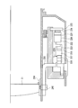
- FIG. 2 is a cross-sectional view showing the configuration of the lens barrel 200 in the present embodiment.
- the lens barrel 200 fixes the vibrator 220 side and drives the lens unit 21.
- the vibrator 220 (vibration wave motor) includes an electromechanical conversion element (hereinafter referred to as a piezoelectric body 221) such as a piezoelectric element or an electrostrictive element that converts electrical energy into kinetic energy, and a piezoelectric body 221. And an elastic body 222 joined.
- the vibrator 220 generates a traveling wave according to the two drive signals supplied from the drive circuit unit 23. In this embodiment, the traveling wave will be described as nine traveling waves as an example.
- the elastic body 222 is made of a metal material having a high resonance sharpness, and its shape is an annular shape.
- the elastic body 222 has a groove on the opposite surface to which the piezoelectric body 221 is bonded, and the tip surface of the protruding portion (the place where there is no groove) serves as a drive surface.
- the driving surface of the elastic body 222 is in pressure contact with the moving element 223.
- the reason for cutting the groove in the elastic body 222 is to make the neutral surface of the traveling wave as close to the piezoelectric body 221 as possible, thereby amplifying the amplitude of the traveling wave on the drive surface of the elastic body 222.
- the portion of the elastic body 222 that is not cut is referred to as a base portion in this embodiment.
- the piezoelectric body 221 is joined to the surface of the base portion opposite to the groove side.
- the drive surface of the elastic body 222 is subjected to a lubricious surface treatment.
- the piezoelectric body 221 is divided into two phases (A phase and B phase) along the circumferential direction. In each of the two phases (A phase and B phase), elements in which the polarization alternates every 1 ⁇ 2 wavelength are arranged.
- the A phase and the B phase of the piezoelectric body 221 are arranged so that an interval of 1 ⁇ 4 wavelength is left between the A phase and the B phase of the piezoelectric body 221.
- the mover 223 is made of, for example, a light metal such as aluminum, and the surface of the sliding surface is subjected to a surface treatment for improving wear resistance.
- the elastic body 222 and the mover 223 are pressed against each other by the force generated from the pressure member 224, and the mover 223 rotates in response to the traveling wave of the elastic body 222.
- the pressure member 224 is located between the piezoelectric body side of the vibrator 220 and the fixing member 225 so that the elastic body 222 and the moving element 223 are pressed against each other.
- the output shaft 227 is coupled to the mover 223 via a rubber member 226.
- the output shaft 227 rotates integrally with the mover 223. That is, the rotational force of the mover 223 is transmitted to the output shaft 227 via the rubber member 226.
- the rubber member 226 is disposed between the output shaft 227 and the mover 223.
- the rubber member 226 is made of, for example, butyl rubber or the like, and absorbs vibration for preventing the vibration from the mover 223 from being transmitted to the output shaft 227 and the function of coupling the mover 223 and the output shaft 227 by rubber adhesiveness. With function.
- the rotational force of the output shaft 227 is transmitted to the planetary roller 228.
- the planetary roller 228 is disposed on the outer periphery of the planetary ring 229.
- the planetary roller 228 is rotated by the rotational force of the output shaft 227 to rotate the planetary ring 229.
- the cam ring 230 is rotated by the rotation of the planetary ring 229. That is, the movement of the vibrator 220 is transmitted to the cam ring 230 via the moving element 223, the output shaft 227, and the planetary roller 228, and the cam ring 230 is rotated.
- the cam ring 230 has a key groove obliquely corresponding to the circumferential direction, and a fixing pin 240 is inserted into the key groove.
- the fixing pin 240 is fixed to the focus ring 250. As the cam ring 230 rotates, the focus ring 250 advances straight in the optical axis direction.
- a magnetic tape and a magnetic sensor are arranged as the encoder 24 between the moving element 223 and the cam ring 230, and the rotational speed of the moving element 223 is detected.
- the drive circuit unit 23 is mounted in a gap between the lens chamber and the lens outer frame.
- the vibrator 220 as the drive source moves.
- the mover 223 rotates.
- This rotational movement is transmitted to the cam ring 230, and the cam ring 230 rotates, whereby the AF lens of the lens unit 21 is driven in the optical axis direction.
- the imaging apparatus 100 captures an image corresponding to a moving image in the configuration illustrated in FIGS. 1 and 2.
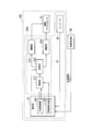
- FIG. 3 is a schematic block diagram showing the lens barrel 200 in the present embodiment.
- the lens barrel 200 includes a vibration actuator 22 and an actuator control device 300.
- the actuator control device 300 includes a drive circuit unit 23, an encoder 24, and a control unit 26.
- the same components as those in FIG. The lens unit 21 and the lens memory unit 25 are not shown.
- the drive circuit unit 23 includes an oscillation unit 231, a phase shift unit 232, and amplification units (233, 234).
- the oscillation unit 231 generates a drive signal having a desired frequency based on the control signals supplied from the phase control unit 261 and the frequency control unit 262 of the control unit 26.
- the oscillator 231 changes the frequency of the drive signal based on the control signal supplied from the frequency controller 262.
- the phase shift unit 232 divides the drive signal generated by the oscillation unit 231 into two drive signals having different phases.
- the phase shift unit 232 supplies the two drive signals to the amplification units 233 and 234.
- the amplification units (233, 234) boost the two drive signals divided by the phase shift unit 232 to desired voltages, respectively.
- the amplifying units (233, 234) supply the two boosted drive signals to the vibrator 220 of the vibration actuator 22. When these two drive signals are supplied, the vibrator 220 generates a traveling wave and drives the moving element 223.
- the encoder 24 (speed detection unit) is constituted by a magnetic encoder or the like, and detects the position and speed of a driving object (for example, the output shaft 227, the cam ring 230, etc.) driven by driving the moving element 223.
- the position information and speed information thus obtained are output to the control unit 26 as electrical signals (detection signals).
- the control unit 26 indirectly obtains the position information and speed information of the AF lens of the lens unit 21 based on the position information and speed information detected by the encoder 24.
- the control unit 26 controls driving of the vibration actuator 22 based on imaging information supplied from the lens barrel 200 or the imaging control unit 10 of the imaging device 100.
- the control unit 26 obtains position information and speed information of the driven object based on the detection signal output from the encoder 24.
- the control unit 26 performs control so that, for example, the AF lens of the lens unit 21 is positioned at the target position from the position information and speed information of the driven object. That is, based on the position information and the speed information, the control unit 26 uses the frequencies of the two drive signals by the oscillation unit 231, the phase difference between the two drive signals by the phase shift unit 232, and the amplification units (233 and 234).
- the voltage of the two drive signals is controlled.
- the control unit 26 finely controls the frequency and phase difference between the two drive signals based on the shooting information (still image mode / moving image mode, etc.).
- the photographing information is supplied from the lens barrel 200 or the imaging control unit 10 of the imaging device 100.
- the control unit 26 includes a phase control unit 261 that controls the phase difference between the two drive signals and a frequency control unit 262 that controls the frequency of the two drive signals.
- the control unit 26 selectively uses the phase control unit 261 and the frequency control unit 262 to control the speed of the vibration actuator 22. Further, the control unit 26 uses the phase control unit 261 to speed the vibration actuator 22 when capturing a moving image based on the shooting information supplied from the lens barrel 200 or the imaging control unit 10 of the imaging device 100. To control.
- the target position of the lens for AF of the lens unit 21 is transmitted to the control unit 26 based on a control signal (imaging information) supplied from the lens barrel 200 or the imaging control unit 10 of the imaging device 100.
- the control unit 26 controls the oscillating unit 231 and the phase shift unit 232 so that the lens unit 21 becomes the target position of the AF lens.
- the oscillating unit 231 generates a drive signal.
- the phase shifter 232 divides the drive signal generated by the oscillator 231 into two drive signals having a phase difference of 90 degrees.
- the phase shifter 232 supplies the two divided drive signals to the amplifiers (233, 234), respectively.
- the amplifying units (233, 234) amplify the supplied drive signal to a desired voltage and output it to the vibration actuator 22.
- Two drive signals output from the amplifying units are applied to the piezoelectric body 221 of the vibrator 220.
- the piezoelectric body 221 is excited by two drive signals. Due to the excitation, a ninth-order bending vibration is generated in the elastic body 222.
- the piezoelectric body 221 is divided into an A phase and a B phase, and two drive signals are applied to the A phase and the B phase, respectively.
- the positional phase of the ninth-order bending vibration generated from the A phase and the ninth-order bending vibration generated from the B phase are shifted by 1 ⁇ 4 wavelength. Further, the phase A drive signal and the phase B drive signal are 90 degrees out of phase. As a result, the two bending vibrations are combined into nine traveling waves.
- the phase difference value ⁇ 90 degrees is an ideal value, and the traveling wave shape is disturbed even at the intermediate value, but the traveling wave is generated.
- elliptical motion occurs at the wavefront of the traveling wave generated in the elastic body 222. Therefore, the moving element 223 that is in pressure contact with the driving surface of the elastic body 222 is frictionally driven by this elliptical motion.
- An encoder 24 is disposed on a driven object (for example, the output shaft 227, the cam ring 230, or the like) driven by driving the moving element 223. The encoder 24 detects the position and speed (rotational speed) of the driven object, and outputs the detected position information and speed information to the control unit 26 as detection signals.
- the control unit 26 obtains the current position and current speed of the lens unit 21 in the AF lens based on the detection signal supplied from the encoder 24.
- the frequency control unit 262 of the control unit 26 controls the frequency of the drive signal output from the oscillation unit 231 based on the position information, speed information, and target position information of the AF lens of the lens unit 21.
- the phase control unit 261 of the control unit 26 When driving the AF lens in the positive direction (for example, the left direction in FIG. 2), the phase control unit 261 of the control unit 26 outputs two drive signals (frequency voltage signal) output from the phase shift unit 232. ) Is controlled to a + (plus) value, for example, +90 degrees.
- the phase control unit 261 When the AF lens is driven in the reverse direction (for example, the right direction in FIG. 2), the phase control unit 261 has a phase difference between the two drive signals (frequency voltage signals) output from the phase shift unit 232. Is controlled to a ⁇ (minus) value, for example, ⁇ 90 degrees.
- the control unit 26 obtains the current shooting mode in the imaging device 100 by a control signal (imaging information) supplied from the imaging control unit 10 of the imaging device 100.
- the current shooting mode is, for example, a still image mode for capturing a still image or a moving image mode for capturing a moving image.
- the control unit 26 uses the frequency control unit 262 to control the frequency of the drive signal output from the oscillation unit 231 when in the still image mode. Further, the control unit 26 uses the phase control unit 261 to calculate the frequency of the drive signal output from the oscillation unit 231 and the phase difference between the two drive signals output from the phase shift unit 232 in the moving image mode. Control. That is, the control unit 26 selectively uses the phase control unit 261 and the frequency control unit 262 to control the speed of the vibration actuator 22. Further, the control unit 26 controls the speed of the vibration actuator 22 using the phase control unit 261 during moving image capturing.
- the phase control unit 261 changes the phase difference between the two drive signals output from the phase shift unit 232 to change the position of the AF lens and Control the speed.
- the phase control unit 261 controls the phase difference between the two drive signals based on information relating the phase difference between the two drive signals to be supplied to the drive circuit unit 23 and the speed of the vibration actuator 22 to thereby vibrate.
- the speed of the actuator 22 is controlled.
- information relating the phase difference between the two drive signals and the speed of the vibration actuator 22 is stored in the in-lens memory unit 25, and the phase control unit 261 determines the phase difference between the two drive signals and the vibration actuator 22.
- Information associated with the speed is read from the in-lens memory unit 25.
- the phase control unit 261 is output from the phase shift unit 232 based on the position information, speed information, and target position information of the lens unit 21 detected by the encoder 24 in the AF lens.
- the phase difference between the two drive signals is controlled. That is, the phase control unit 261 controls the phase difference between the two drive signals based on the above-described information read from the in-lens memory unit 25 and the speed information of the vibration actuator 22 detected by the encoder 24. Thereby, the phase control unit 261 controls the speed of the vibration actuator 22.
- FIG. 4 is a graph showing an example of the characteristics of the vibration actuator 22 in the present embodiment.
- the graph shows the relationship between the phase difference between the two drive signals and the rotation speed (rotation speed) of the vibration actuator 22.
- the vertical axis indicates the rotation speed [rpm] (times per minute) of the vibration actuator 22, and the horizontal axis indicates the phase difference [degree] between the two drive signals.
- the phase difference between the two drive signals indicates a region where the vibration actuator 22 operates stably.
- the phase difference between the two drive signals indicates a region where the vibration actuator 22 does not operate.
- the speed (rotational speed) of the vibration actuator 22 is 0 rpm.
- the speed (rotational speed) of the vibration actuator 22 is 0 rpm until the phase difference between the two drive signals is about ⁇ 5 degrees. That is, the vibration actuator 22 does not operate in the phase difference range ( ⁇ 5 degrees to +5 degrees) between the two drive signals in the waveform 202.
- the vibration actuator 22 rotates in the positive rotation direction.
- the phase difference between the two drive signals indicates a region where the vibration actuator 22 operates stably in the positive rotation direction.
- the vibration actuator 22 rotates in the negative rotation direction.
- the phase difference between the two drive signals indicates a region where the vibration actuator 22 operates stably in the negative rotation direction.
- the speed (rotational speed) of the vibration actuator 22 is maximized.
- the operation (rotation) of the vibration actuator 22 is unstable, and may repeatedly rotate or stop at a low speed.
- a region where the operation (rotation) of the vibration actuator 22 is unstable is referred to as an unstable region. That is, the unstable region indicates a phase difference range where the operation of the vibration actuator 22 becomes unstable.
- the unstable region (rotational speed unstable region 204) indicates a phase difference range from about ⁇ 20 degrees to about ⁇ 5 degrees and a phase difference range from about +5 degrees to about +15 degrees. Note that the unstable region may have different phase difference ranges between the positive rotation direction and the negative rotation direction. Therefore, the phase control unit 261 may perform different control in the positive rotation direction and the negative rotation direction based on the unstable region.
- the actuator control device 300 information associating the phase difference between the two drive signals and the speed of the vibration actuator 22 as shown in FIG. 4 is stored in the in-lens memory unit 25.
- the phase control unit 261 controls the phase difference between the two drive signals based on information relating the phase difference between the two drive signals stored in the in-lens memory unit 25 and the speed of the vibration actuator 22 to thereby vibrate.
- the speed of the actuator 22 is controlled.
- the information stored in the in-lens memory unit 25 includes an unstable region (information) indicating a phase difference range in which the operation of the vibration actuator 22 becomes unstable.
- the phase control unit 261 controls the speed of the vibration actuator 22 by controlling the phase difference between the two drive signals based on the unstable region stored in the in-lens memory unit 25.
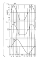
- FIG. 5 is a diagram illustrating an operation of the actuator control device 300 according to the present embodiment.
- FIG. 5A is a graph showing the relationship between time and the phase difference between two drive signals in the actuator control device 300.
- the vertical axis indicates the phase difference [degree] between two drive signals
- the horizontal axis indicates time.
- a waveform 205 shows a change in the phase difference between the two drive signals.
- FIG. 5B is a graph showing the relationship between time and the speed of the vibration actuator 22 in the actuator control device 300.
- the vertical axis indicates the speed (rotational speed) [rpm] of the vibration actuator 22
- the horizontal axis indicates time.
- a waveform 206 indicates a change in the speed of the vibration actuator 22.
- FIG. 5C is a graph showing the relationship between time and the position of the AF lens of the lens unit 21 in the actuator control device 300.
- the vertical axis indicates the position of the AF lens
- the horizontal axis indicates time.
- a waveform 207 indicates a change in the position of the AF lens.
- the time scale of time on the horizontal axis is common and corresponds to each other.
- an operation when the imaging apparatus 100 is in a moving image mode for capturing a moving image is shown.
- the vibration actuator 22 is supplied with two drive signals having a constant frequency and a phase difference of 0 degree immediately before the moving image is captured. A case where output is stopped will be described.
- the phase control unit 261 will be described assuming that information and an unstable region (information) in which the phase difference between the two drive signals and the speed of the vibration actuator 22 are associated with each other are read from the in-lens memory unit 25 in advance.
- the phase control unit 261 controls the phase difference between the two drive signals to 0 degrees. Therefore, in the waveform 205, the phase difference between the two drive signals is 0 degrees, in the waveform 206, the speed of the vibration actuator 22 is 0 rpm, and in the waveform 207, the position of the AF lens is 0. That is, the vibration actuator 22 is in a stopped state.
- the imaging control unit 10 instructs the control unit 26 to move the AF lens to a target position (for example, position L1).
- the phase control unit 261 is based on the information that associates the phase difference between the two drive signals read from the in-lens memory unit 25 with the speed of the vibration actuator 22 and the unstable region (information), and the phase difference between the two drive signals. Start controlling.
- the phase control unit 261 increases the amount of change in the phase difference between the two drive signals compared to the amount of change in the phase difference in the period from time t2 to time t3. This is to avoid using the vibration actuator 22 in an unstable region (rotation unstable region). That is, the phase control unit 261 performs control so that the time during which the phase difference between the two drive signals passes through the unstable region (the time for driving the vibration actuator 22 in the unstable region) is shortened. That is, when the vibration actuator 22 is controlled in the unstable region, the phase control unit 261 changes the phase difference between the two drive signals more than when the vibration actuator 22 is controlled in the phase difference range excluding the unstable region.
- the phase difference range excluding the unstable region refers to the phase difference range excluding the unstable region in the phase difference range controlled by the phase control unit 261.
- the unstable region is described as a range where the phase difference is +5 degrees to +30 degrees and a phase difference is ⁇ 5 degrees to ⁇ 30 degrees.
- the phase difference between the two drive signals changes sharply from 0 degree to +30 degrees.
- the speed of the vibration actuator 22 changes in the positive direction in accordance with the change in the phase difference between the two drive signals.
- the phase control unit 261 gradually widens the phase difference between the two drive signals and increases the speed of the vibration actuator 22.
- the phase controller 261 linearly changes the phase difference between the two drive signals from +30 degrees to +90 degrees.
- the phase difference between the two drive signals changes from +30 degrees to +90 degrees.
- the speed of the vibration actuator 22 changes more slowly than the speed change in the unstable region.
- the position of the AF lens gradually approaches the target position L1.
- phase control unit 261 sets the phase difference between the two drive signals to +90 degrees and sets the speed of the vibration actuator 22 to the maximum speed.
- the phase control unit 261 has approached the target position L1, so that the phase difference between the two drive signals is gradually narrowed to reduce the speed of the vibration actuator 22.
- the phase control unit 261 changes the phase difference between the two drive signals from +90 degrees to +30 degrees.
- the waveform 205 the phase difference between the two drive signals changes from +90 degrees to +30 degrees.
- the speed of the vibration actuator 22 is gradually reduced.
- the position of the AF lens gradually approaches the target position L1.
- the phase control unit 261 fixes the phase difference between the two drive signals with a phase difference slightly larger than the unstable region in order to bring the target position L1 close to the target position L1, and an AF lens. Is moved closer to the target position L1.
- the phase control unit 261 increases the amount of change in the phase difference between the two drive signals compared to the amount of change in the phase difference in the period from time t4 to time t5. This is to avoid using the vibration actuator 22 in an unstable region (rotation unstable region). That is, the phase control unit 261 performs control so as to shorten the time (the driving time) that the phase difference between the two drive signals passes through the unstable region. That is, when the vibration actuator 22 is controlled in the unstable region, the phase control unit 261 changes the phase difference between the two drive signals more than when the vibration actuator 22 is controlled in the phase difference range excluding the unstable region. Increase Thereby, in the waveform 205, the phase difference between the two drive signals changes steeply from +30 degrees to 0 degrees.
- the phase control unit 261 has reached the target position L1, and therefore sets the phase difference between the two drive signals to 0 degrees. Therefore, in the waveform 205, the phase difference between the two drive signals is 0 degrees, in the waveform 206, the speed of the vibration actuator 22 is 0 rpm, and in the waveform 207, the position of the AF lens is 0. That is, the vibration actuator 22 stops and the AF lens stops at the target position L1. In this state, the two drive signals are continuously supplied to the vibration actuator 22 with the phase difference being 0 degree.
- the phase control unit 261 performs the same control as in the period from t0 to t8 by reversing the sign of the phase difference between the two drive signals.
- the target position of the AF lens is the position L2.
- the phase control unit 261 again performs the same control as in the period from t0 to t8.
- the target position of the AF lens is position 0.
- the AF lens returns to the initial position 0.
- the phase control unit 261 stores the above-described phase difference control stored in the in-lens memory unit 25, the information relating the phase difference between the two drive signals and the speed of the vibration actuator 22, and the unstable region (information). Based on the above, the phase difference between the two drive signals is controlled. Further, the phase control unit 261 controls the phase difference between the two drive signals based on the speed information and position information of the vibration actuator 22 detected by the encoder 24. In addition, since the rotationally unstable region may have a difference depending on the direction of rotation, different values may be stored in the in-lens memory unit 25 in both the positive and negative rotational directions.
- the phase control unit 261 controls the phase difference between the two drive signals based on the information that associates the phase difference between the two drive signals and the speed of the vibration actuator 22, and thereby the speed of the vibration actuator 22. To control. Thereby, since a deceleration pattern can be assumed in advance, the vibration actuator 22 can be accurately controlled while shortening the operation time. Since the useless operation of the vibration actuator 22 can be reduced, it is possible to reduce the sound generated when the vibration actuator 22 is driven.
- the phase control unit 261 controls the speed of the vibration actuator 22 based on the phase difference between the two drive signals. The two drive signals continue to be supplied to the vibration actuator 22 with the phase difference being 0 degrees even when the vibration actuator 22 is in a stopped state.
- the actuator control device 300, the lens barrel 200, and the imaging device 100 can reduce the sound that is generated when the vibration actuator 22 is driven.
- the phase control unit 261 controls the vibration actuator 22 in another phase difference range when controlling the vibration actuator 22 in the phase difference range where the operation of the vibration actuator 22 becomes unstable based on the unstable region information.
- the amount of change in the phase difference between the two drive signals is made larger than in the case of doing so. That is, the phase control unit 261 performs control so as to shorten the time (the driving time) that the phase difference between the two drive signals passes through the unstable region. Thereby, the sound produced when driving the vibration actuator 22 in the unstable region can be reduced.
- the actuator control device 300 includes an encoder 24 (speed detection unit) that detects the speed of the vibration actuator.
- the phase control unit 261 determines the position of the two drive signals based on the information relating the phase difference between the two drive signals and the speed of the vibration actuator 22 and the speed of the vibration actuator 22 detected by the encoder 24.
- the speed of the vibration actuator 22 is controlled by controlling the phase difference. Accordingly, the phase control unit 261 can control the speed of the vibration actuator 22 while grasping the speed of the vibration actuator 22 and the position of the AF lens. Therefore, the actuator control device 300 can control the vibration actuator 22 with higher accuracy while shortening the operation time. Therefore, since the useless operation of the vibration actuator 22 can be reduced, the sound generated when the vibration actuator 22 is driven can be further reduced.
- the phase control unit 261 compares information that associates the phase difference between the two drive signals and the speed of the vibration actuator 22 with information stored in the in-lens memory unit 25. If there is a significant deviation, the stored information can be updated.
- the phase control unit 261 changes the phase difference between the two drive signals.
- the speed information of the corresponding vibration actuator 22 is acquired from the encoder 24.
- the phase control unit 261 associates the speed information detected by the encoder 24 (speed detection unit) with the phase difference between the two drive signals and stores them in the in-lens memory unit 25. Thereby, the phase control unit 261 can control the vibration actuator 22 based on the latest information. Therefore, the actuator control device 300 can further reduce the sound generated when the vibration actuator 22 is driven even when the characteristics of the vibration actuator 22 change due to aging or temperature change.
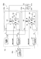
- FIG. 6 is a schematic block diagram showing the actuator control device 300a in the present embodiment.
- the actuator control device 300a includes a drive circuit unit 23a and a phase control unit 261a.
- the actuator control device 300a includes the encoder 24, the in-lens memory unit 25, and the control unit 26 as in the actuator control device 300 shown in FIG. 1, but is not shown in FIG.
- the drive circuit unit 23a generates two drive signals based on the control signal supplied from the phase control unit 261a via the signal lines P1 and P2.
- the drive circuit unit 23a outputs the two generated drive signals to the vibration actuator 22 via the signal lines C1 and C2. That is, the drive circuit unit 23 a supplies two drive signals (a first drive signal and a second drive signal) to the vibration actuator 22.
- the drive circuit unit 23a includes an amplification unit (233a, 234a), a DC power supply circuit unit 235, and a switching control circuit unit (236, 237).
- the amplifying unit 233a amplifies the signal on the signal line B1 and outputs the amplified signal to the signal line C1.
- the amplifying unit 233a includes a transformer unit 331, an NMOS transistor (N-channel metal oxide semiconductor field effect transistor) (332, 333), a diode (334, 335), and an inverter 336.
- the transformer unit 331 first transformer unit
- one terminal of the primary side winding is connected to the signal line A, and the other terminal is connected to the node N1.
- the transformer unit 331 has one terminal of the secondary winding connected to the signal line C1 and the other terminal connected to the node N2.
- the transformer unit 331 connects the DC power supplied from the DC power supply circuit unit 235 to the primary side winding, and outputs a drive signal (first drive signal) from the secondary side winding.
- the drive signal (first drive signal) output from the transformer unit 331 is supplied to the piezoelectric body 221a of the vibration actuator 22 via the signal line C1.
- the NMOS transistor 332 (first switch portion) has a source terminal connected to the ground, a drain terminal connected to the node N1, and a gate terminal connected to the signal line B1.
- the NMOS transistor 332 switches the current I1 flowing through the primary side winding of the transformer unit 331 between a conduction state and a non-conduction state.
- the NMOS transistor 333 (second switch portion) has a source terminal connected to the ground, a drain terminal connected to the node N2, and a gate terminal connected to the node N3.
- the NMOS transistor 333 switches the current flowing through the secondary winding of the transformer unit 331 between a conductive state and a non-conductive state.
- the diode 334 has an anode terminal connected to the ground and a cathode terminal connected to the node N1.
- the diode 335 has an anode terminal connected to the ground and a cathode terminal connected to the node N2.
- Inverter 336 has an input terminal connected to signal line B1, and an output terminal connected to node N3. The inverter 336 logically inverts the signal of the signal line B1 and outputs it.
- the amplifying unit 234a amplifies the signal on the signal line B2 and outputs the amplified signal to the signal line C2.
- the amplifying unit 234a includes a transformer unit 341, NMOS transistors (342, 343), diodes (344, 345), and an inverter 346.
- the transformer unit 341 second transformer unit
- one terminal of the primary winding is connected to the signal line A, and the other terminal is connected to the node N4.
- the transformer unit 341 one terminal of the secondary side winding is connected to the signal line C2, and the other terminal is connected to the node N5.
- the transformer unit 341 connects the DC power supplied from the DC power supply circuit unit 235 to the primary side winding, and outputs a drive signal (second drive signal) from the secondary side winding.
- the drive signal (second drive signal) output from the transformer unit 341 is supplied to the piezoelectric body 221b of the vibration actuator 22 via the signal line C2.
- the NMOS transistor 342 (third switch unit) has a source terminal connected to the ground, a drain terminal connected to the node N4, and a gate terminal connected to the signal line B2.
- the NMOS transistor 342 switches the current I2 flowing through the primary winding of the transformer unit 341 between a conductive state and a non-conductive state.
- the NMOS transistor 343 (fourth switch unit) has a source terminal connected to the ground, a drain terminal connected to the node N5, and a gate terminal connected to the node N6.
- the NMOS transistor 343 switches the current flowing through the secondary winding of the transformer unit 341 between a conductive state and a non-conductive state.
- the diode 344 has an anode terminal connected to the ground and a cathode terminal connected to the node N4.
- the diode 345 has an anode terminal connected to the ground and a cathode terminal connected to the node N5.
- Inverter 346 has an input terminal connected to signal line B2, and an output terminal connected to node N6. The inverter 346 inverts the signal of the signal line B2 and outputs it.
- the switching control circuit unit 236 outputs an output signal for controlling the conduction state of the NMOS transistors (332, 333) of the amplification unit 233a based on the drive signal supplied from the pulse generation circuit unit 263 via the signal line P1. Output to B1.
- the switching control circuit unit 237 outputs an output signal for controlling the conduction state of the NMOS transistors (342, 343) of the amplification unit 234a based on the drive signal supplied from the pulse generation circuit unit 263 via the signal line P2. Output to B2.
- the phase control unit 261a is included in the control unit 26, and controls the vibration actuator 22 when the CPU executes a program stored in the ROM.
- the phase controller 261a controls the speed of the vibration actuator 22 by controlling the phase difference between the two drive signals (the first drive signal and the second drive signal). That is, the phase control unit 261a controls the phase difference between the two drive signals by adjusting the timing at which the NMOS transistor 332 and the NMOS transistor 342 are turned off.
- the phase control unit 261a controls the phase difference between the two drive signals by changing the timing at which one of the NMOS transistor 332 and the NMOS transistor 342 is turned off.
- phase control unit 261a includes a part of the oscillation unit 231 and the phase shift unit 232 as the pulse generation circuit unit 263.
- the pulse generation circuit unit 263 operates the vibration actuator 22 at a desired speed N. Therefore, the pulse generation circuit unit 263 generates a drive signal having a drive frequency f corresponding to a desired speed N.
- the pulse generation circuit unit 263 divides the drive signal having the drive frequency f into two drive signals and outputs them to the signal lines P1 and P2. Further, the pulse generation circuit unit 263 controls the phase difference between the two drive signals.
- FIG. 7 is a schematic block diagram showing the switching control circuit unit 236 in the present embodiment.
- the switching control circuit unit 236 includes a resistance element (361, 364), a diode 362, a Schmitt trigger buffer 363, a capacitor 365, a Schmitt trigger inverter 366, a flip-flop 367, an inverter 368, and a NAND gate 369.
- the resistance element 361 is connected between the node N1 that is the drive waveform feedback signal line and the input terminal of the Schmitt trigger buffer 363.
- the diode 362 has an anode terminal connected to the input terminal of the Schmitt trigger buffer 363 and a cathode terminal connected to the power supply line of the logic circuit.
- the Schmitt trigger buffer 363 is connected between the resistance element 361 and the resistance element 364, and performs waveform shaping of the drive waveform feedback signal.
- the resistance element 364 is connected between the output terminal of the Schmitt trigger buffer 363 and the input terminal of the Schmitt trigger inverter 366.
- the capacitor 365 has one terminal connected to the ground and the other terminal connected to the input terminal of the Schmitt trigger inverter 366.
- the resistance element 364 and the capacitor 365 function as a low-pass filter that cuts a high frequency component of the drive waveform feedback signal.
- the Schmitt trigger inverter 366 has an input terminal connected to the resistance element 364 and an output terminal connected to the CLK (clock) terminal of the flip-flop 367.
- the Schmitt trigger inverter 366 shapes the waveform of the low-pass filter output from the resistor element 364 and the capacitor 365, performs logical inversion, and outputs the resultant signal as the CLK signal of the flip-flop 367.
- the drive waveform feedback signal supplied from the primary winding of the transformer unit 331 is subjected to waveform shaping and logic via the resistance element 361, the diode 362, the Schmitt trigger buffer 363, the resistance element 364, and the Schmitt trigger inverter 366. Inverted.
- the inverter 368 has an input terminal connected to the signal line P1 and an output terminal connected to the PRE terminal of the flip-flop 367.
- the inverter 368 logically inverts the signal supplied from the pulse generation circuit unit 263 via the signal line P1 and supplies the inverted signal as the PRE signal (set signal) of the flip-flop 367.
- the flip-flop 367 has a D terminal connected to the ground, a CLR terminal connected to the motor ON / OFF signal line, and a Q terminal connected to one of the input terminals of the NAND gate 369.
- the motor ON / OFF signal is a signal that is supplied from the control unit 26 and switches whether to supply a drive signal to the vibration actuator 22.
- the flip-flop 367 is set and outputs the H state to the Q output when the signal of the signal line P1 is in the H (high) state. Further, when the signal on the signal line P1 is in the L (low) state, the flip-flop 367 outputs the L state to the Q output when the drive waveform feedback signal changes from the H state to the L state.
- the NAND gate 369 has one input terminal connected to the Q terminal of the flip-flop 367, the other input terminal connected to the inverter 368, and the output terminal connected to the signal line B1.
- the switching control circuit unit 237 has the same configuration as the switching control circuit unit 236 shown in FIG. However, in the switching control circuit unit 237, the signal line P2 is connected instead of the signal line P1, and the signal line B2 is connected instead of the signal line B1. In the switching control circuit unit 237, a drive waveform feedback signal supplied from the primary side winding of the transformer unit 341 is connected instead of the drive waveform feedback signal supplied from the primary side winding of the transformer unit 331.
- the basic operation of the actuator control device 300a is the same as that of the actuator control device 300 in the first embodiment.
- the operation of the actuator control device 300a differs from the operation of the actuator control device 300 in that the configuration of the drive circuit unit 23a is different and the phase control unit 261a includes a pulse generation circuit unit 263.
- the control unit 26 uses the pulse generation circuit unit 263 of the phase control unit 261a to control the frequency and phase difference between the two drive signals (signals of the signal lines P1 and P2).
- the pulse generation circuit unit 263 operates the vibration actuator 22 at a desired speed N. Therefore, the pulse generation circuit unit 263 generates a drive signal having a drive frequency f corresponding to a desired speed N.
- the pulse generation circuit unit 263 divides the drive signal having the drive frequency f into two drive signals (pulse signals) and outputs them to the signal lines P1 and P2.
- the pulse signal of the signal line P1 output from the pulse generation circuit unit 263 becomes a signal of the signal line B1 through the switching control circuit unit 236, and the NMOS transistors (332, 333) of the amplification unit 233a are turned on or off. Switch. By controlling the NMOS transistors (332, 333) to be switched between a conductive state and a non-conductive state, a boosted drive signal having the same frequency f as the pulse signal of the signal line P1 is applied to the secondary winding of the transformer unit 331. Is output to the signal line C1.
- the pulse signal of the signal line P2 output from the pulse generation circuit unit 263 becomes a signal of the signal line B2 through the switching control circuit unit 237, and the NMOS transistors (342, 343) of the amplification unit 234a are turned on or off. Switch to state.
- the NMOS transistors (342, 343) By controlling the NMOS transistors (342, 343) to be switched between the conductive state and the non-conductive state, the boosted drive signal having the same frequency f as the pulse signal of the signal line P2 is applied to the secondary winding of the transformer unit 341. Is output to the signal line C2.
- the two boosted drive signals generated in the secondary windings of the transformer units 331 and 341 are supplied to the piezoelectric bodies (221a and 221b) via the signal lines C1 and C2, respectively.
- the piezoelectric bodies (221a, 221b) vibrate at the same frequency f as the pulse signal output from the pulse generation circuit unit 263.
- the signals (two drive signals) of the signal lines C1 and C2 are out of phase based on the control by the phase control unit 261a.
- the phase difference between the signals on the signal lines C1 and C2 (two drive signals) is adjusted by adjusting the timing at which the NMOS transistor 332 and the NMOS transistor 342 are turned off by the pulse signal output from the pulse generation circuit unit 263. Be controlled.
- the vibration actuator 22 is driven by supplying signals (two drive signals) of the signal lines C1 and C2 to the piezoelectric bodies (221a and 221a).
- the actuator control device 300a when the vibration actuator 22 is driven, the secondary winding of the transformer 331 (or 341) and the piezoelectric body 221a (or 221a) are connected in series at the cycle of the drive frequency f.
- the NMOS transistor 333 (or 343) provided on the circuit is turned off for a certain period. Thereby, free vibration generated between the transformer 331 (or 341) and the piezoelectric body 221a (or 221b) is suppressed.
- the phase difference between the two drive signals is controlled by varying the time during which the NMOS transistors (333, 343) of the primary windings in the two transformer units (331, 341) are turned on. To do. That is, in the signal of the signal line B1 and the signal of the signal line B2, the control is performed such that the time (period) of the L state (non-conduction state) is made equal and the time (period) of the H state (conduction state) is different. This is performed by the phase controller 261a. Actually, the pulse generation circuit unit 263 of the phase control unit 261a adjusts the timing of the signals on the signal lines P1 and P2.
- the pulse generation circuit unit 263 is realized by adjusting the conduction state time of the NMOS transistors (333, 343). That is, the pulse generation circuit unit 263 adjusts the timing at which the NMOS transistors (333, 343) are turned off.
- the pulse generation circuit unit 263 performs control to add a phase difference to the drive signal of the signal line C2 with respect to the drive signal of the signal line C1 that constantly outputs a specific frequency.
- the pulse generation circuit unit 263 gradually changes the time during which the NMOS transistor 343 is turned on by the signal on the signal line B2. Thereby, a phase difference can be made between the drive signal of the signal line C1 and the drive signal of the signal line C2.
- the two boosted drive signals are roughly divided into a half-wave rectification portion and a time proportional portion, respectively. That is, in the actuator control device 300a, the phase difference between the two drive signals can be changed by adjusting the time proportional part in the drive signal of the signal line C2 out of the two parts.
- the reason for not changing the stepwise phase difference is to realize smooth speed control that makes use of the phase difference and to reduce abnormal noise that occurs rarely when the stepwise phase difference is changed. It is.
- FIG. 8 shows waveforms in the drive signals of the signal lines C1 and C2 with the phase difference as described above.
- FIG. 8 is a diagram illustrating an example of control of the actuator control device 300a in the present embodiment.
- the graph shows phase difference control in the drive signals (two drive signals) of the signal lines C1 and C2.
- the horizontal axis represents time
- the vertical axis represents the voltage [V] of the drive signal.
- a waveform 208 shows the drive signals of the signal lines C1 and C2 when the phase difference is 0 degree. Since the phase difference is 0 degree, the two drive signals overlap.
- a waveform 209 shows a drive signal of the signal line C2 when the phase difference is ⁇ 90 degrees.
- a waveform 210 shows the drive signal of the signal line C2 when the phase difference is gradually changed from ⁇ 90 degrees to ⁇ 60 degrees. In the waveform 210, it can be seen that the conduction time of the NMOS transistor 343 is gradually changed, the phase difference changes from ⁇ 90 degrees to ⁇ 60 degrees, and the difference from the waveform 209 increases. Note that the pulse generation circuit unit 263 realizes the control of the phase difference in the driving signals of the signal lines C1 and C2 described above by, for example, software processing by the CPU.
- the drive circuit unit 23a includes the transformer unit 331 (first transformer unit), the transformer unit 341 (second transformer unit), and the NMOS transistor 332 (first switch unit). ), An NMOS transistor 333 (second switch portion), an NMOS transistor 342 (third switch portion), and an NMOS transistor 343 (fourth switch portion).
- the transformer unit 331 connects a DC power source to the primary side winding, and outputs a first drive signal from the secondary side winding.
- the transformer unit 341 connects a DC power source to the primary side winding and outputs a second drive signal from the secondary side winding.
- the NMOS transistor 332 switches the current flowing through the primary winding of the transformer unit 331 between a conductive state and a non-conductive state.
- the NMOS transistor 342 switches the current flowing through the primary winding of the transformer unit 341 between a conductive state and a non-conductive state.
- phase control unit 261a adjusts the time (period) during which the NMOS transistor 332 and the NMOS transistor 342 are in a conductive state, whereby two drive signals (a first drive signal and a second drive signal) are changed. Control the phase difference.
- the pulse generation circuit unit 263 of the phase control unit 261a adjusts the timing at which the NMOS transistor 332 and the NMOS transistor 342 are in a non-conducting state, whereby two drive signals (first drive signal and second drive signal). Control the phase difference between the signal and
- the two drive signals are continuously supplied to the vibration actuator 22 with the phase difference being 0 degrees even when the vibration actuator 22 is stopped. That is, it is possible to reduce the sound generated in the piezoelectric body 221 when applying or stopping the drive voltages of the two drive signals. Therefore, it is possible to reduce the sound generated when the vibration actuator 22 is driven. As a result, the actuator control device 300a can reduce the sound generated when the vibration actuator 22 is driven.
- the pulse generation circuit unit 263 changes the timing at which one of the NMOS transistor 332 and the NMOS transistor 342 becomes non-conductive.
- the actuator control device 300a can gradually change the phase difference between the two drive signals. Therefore, in the speed of the vibration actuator 22, smooth control utilizing the phase difference can be realized, and unusual noise that occurs rarely when the stepwise phase difference is changed can be reduced.
- the present invention is not limited to the above embodiments, and can be modified without departing from the spirit of the present invention.
- the mode in which unstable region information is included in the information that associates the phase difference between the two drive signals with the speed of the vibration actuator 22 has been described.
- the unstable area information may be stored in the in-lens memory unit 25 alone.
- the phase control unit 261 controls the speed of the vibration actuator 22 by changing the phase difference between the two drive signals based on the unstable region information read from the in-lens memory unit 25.
- the encoder 24 stores both information relating the phase difference between the two drive signals and the speed of the vibration actuator 22 and controls the speed of the vibration actuator 22.
- the form of detecting the speed of the vibration actuator 22 has been described, but other forms may be used.
- the actuator control device 300 may include two encoders, a first encoder and a second encoder.
- the first encoder first speed detection unit
- the second encoder second speed detection unit
- the first encoder may detect the speed and position of the vibration actuator 22 when controlling the speed of the vibration actuator 22.
- the second encoder second speed detection unit
- the in-lens memory unit 25 has been described as being provided in the actuator control device 300 (or 300a). However, it may be provided outside the actuator control device 300 (or 300a). Even if the actuator control device 300 (or 300a) is configured to include the in-lens memory unit 25 outside, it is possible to reduce the sound generated when the vibration actuator 22 is driven as in the above embodiments.
- the phase control unit 261a controls the phase difference between the two drive signals based on the information that associates the phase difference between the two drive signals and the speed of the vibration actuator 22 to thereby vibrate.
- the speed of the actuator 22 may be controlled.
- the phase control unit 261a performs the vibration actuator in the phase difference range excluding the unstable region.
- the amount of change in the phase difference between the two drive signals may be made larger than in the case of controlling 22.
- the mode in which the phase control of the two drive signals by the phase control unit 261 (or 261a) is performed when a moving image is captured has been described. However, it may be applied when capturing a still image. Further, the mode of driving the AF lens of the lens unit 21 has been described. However, the phase control of the two drive signals by the phase controller 261 (or 261a) may be driven by another actuator using a vibration actuator.
- the present invention may be applied to a vibration actuator for zoom and a vibration actuator for VR (Vibration Reduction). Even in this case, the sound generated when the vibration actuator 22 is driven can be reduced as in the above embodiments.
- the mode in which the pulse generation circuit unit 263 adjusts the time proportional portion in the drive signal of the signal line C2 to change the phase difference has been described.
- the time proportional part in the drive signal of the signal line C1 may be adjusted, or the time proportional part may be relatively adjusted in both the drive signals of the signal lines C1 and C2. That is, the pulse generation circuit unit 263 may change the phase difference by relatively changing both the drive signals of the signal lines C1 and C2. Even in this case, the sound generated when the vibration actuator 22 is driven can be reduced as in the second embodiment.
- control unit 26 selectively controls the speed of the vibration actuator 22 using the phase control unit 261 and the frequency control unit 262.
- the present invention is not limited to this. Absent.
- the phase controller 261 and the frequency controller 262 may be used in combination to control the speed of the vibration actuator 22.
- the vibration actuator 22 may be controlled differently in the positive rotation direction and the negative rotation direction.
- each unit of the actuator control device 300 may be realized by dedicated hardware.
- Each unit of the actuator control device 300 (or 300a) is configured by a memory and a CPU, and each function of the actuator control device 300 (or 300a) may be realized by a program.
- the above-described actuator control device 300 (or 300a) has a computer system inside.
- the process of driving the vibration actuator 22 described above is stored in a computer-readable recording medium in the form of a program, and the above process is performed by the computer reading and executing this program.
- the computer-readable recording medium means a magnetic disk, a magneto-optical disk, a CD-ROM, a DVD-ROM, a semiconductor memory, or the like.
- the computer program may be distributed to the computer via a communication line, and the computer that has received the distribution may execute the program.
Landscapes
- Physics & Mathematics (AREA)
- General Physics & Mathematics (AREA)
- Optics & Photonics (AREA)
- Studio Devices (AREA)
- General Electrical Machinery Utilizing Piezoelectricity, Electrostriction Or Magnetostriction (AREA)
- Lens Barrels (AREA)
Abstract
アクチュエータ制御装置(300)は、振動アクチュエータ(22)に位相の異なる駆動信号を供給する駆動回路部(23)と、前記駆動信号の位相差と、前記振動アクチュエータ(22)の回転に関する情報と、を関連付けた関連情報に基づいて、前記駆動信号の位相差を制御する位相制御部(261)とを備える。
Description
本発明は、アクチュエータ制御装置、レンズ鏡筒、及び撮像装置に関する。
本願は、2011年10月12日に出願された日本国特願2011-224921号に基づき優先権を主張し、その内容をここに援用する。
本願は、2011年10月12日に出願された日本国特願2011-224921号に基づき優先権を主張し、その内容をここに援用する。
振動アクチュエータは、圧電体の伸縮を利用して弾性体の振動面に進行性振動波を発生させる。この進行性振動波によって、駆動面に楕円運動が生じ、楕円運動の波頭に加圧接触された移動子が駆動される(例えば、特許文献1を参照)。
このような振動アクチュエータは、低回転においても高いトルクを有する特徴がある。
そのため、このような振動アクチュエータを駆動装置に搭載した場合に、駆動装置のギアを省略することができる。そのため、ギアによる騒音を低減させたり、位置決め精度を向上させたりできるといった利点がある。
このような振動アクチュエータは、低回転においても高いトルクを有する特徴がある。
そのため、このような振動アクチュエータを駆動装置に搭載した場合に、駆動装置のギアを省略することができる。そのため、ギアによる騒音を低減させたり、位置決め精度を向上させたりできるといった利点がある。
一方で、このような振動アクチュエータは、写真フィルムを用いた撮像装置(カメラ)の交換レンズ用として利用されてきた。しかし、近年、電子カメラの進歩により、電子カメラの交換レンズ用に、その利用がシフトしてきている。このような電子カメラ(撮像装置)では、静止画の撮像の他にも、動画の撮像も行うことが可能である。動画の撮像を行う場合には、動画の撮像と同時に音声の取り込みが行えることが、市場から要望されている。
しかしながら、特許文献1に示される振動アクチュエータを用いた電子カメラ(撮像装置)では、振動アクチュエータを駆動する際に微小な音が発生する場合がある。例えば、オートフォーカス(以下、AFという)によりレンズを駆動させようとした場合、振動アクチュエータの駆動を開始するために駆動信号をON状態にする際に、微小な音が発生することがある。動画の撮像と同時に音声の取り込む場合に、この微小な音が、音声を検出するマイクに取り込まれてしまうという問題がある。
特に動画を撮像する際に、AFレンズを小刻みに前後させて、適正な焦点位置を追従させる動作(ウォブリング動作)を行う場合がある。この場合には、振動アクチュエータは、正方向に駆動→一旦止めて駆動信号の位相差設定→反対方向に駆動→一旦止めて駆動信号の位相差設定→・・・・の繰り返し、という動作をする。このように振動アクチュエータを一旦止めて、再び駆動させる際に、微小な音が発生して、音声を検出するマイクに取り込まれてしまうという問題がある。
特に動画を撮像する際に、AFレンズを小刻みに前後させて、適正な焦点位置を追従させる動作(ウォブリング動作)を行う場合がある。この場合には、振動アクチュエータは、正方向に駆動→一旦止めて駆動信号の位相差設定→反対方向に駆動→一旦止めて駆動信号の位相差設定→・・・・の繰り返し、という動作をする。このように振動アクチュエータを一旦止めて、再び駆動させる際に、微小な音が発生して、音声を検出するマイクに取り込まれてしまうという問題がある。
本発明の態様の目的は、振動アクチュエータを駆動する際に生じる音を低減することができるアクチュエータ制御装置、レンズ鏡筒、及び撮像装置を提供することにある。
本発明の態様は、振動アクチュエータに位相の異なる駆動信号を供給する駆動回路部と、前記駆動信号の位相差と、前記振動アクチュエータの回転に関する情報と、を関連付けた関連情報に基づいて、前記駆動信号の位相差を制御する位相制御部とを備えることを特徴とするアクチュエータ制御装置である。
また、本発明の態様は、振動アクチュエータに2つの駆動信号を供給する駆動回路部と、前記2つの駆動信号において、前記振動アクチュエータの動作が不安定になる位相差範囲を示す不安定領域情報に基づいて、前記動作が不安定になる前記位相差範囲において前記振動アクチュエータを制御する場合には、前記動作が不安定になる前記位相差範囲を除いた位相差範囲で前記振動アクチュエータを制御する場合よりも、位相差を大きく変化させて、前記振動アクチュエータの速度を制御する位相制御部とを備えることを特徴とするアクチュエータ制御装置である。
また、本発明の態様は、振動アクチュエータに第1の駆動信号及び第2の駆動信号を供給する駆動回路部と、前記第1の駆動信号と前記第2の駆動信号との位相差を制御して、前記振動アクチュエータの速度を制御する位相制御部とを備え、前記駆動回路部は、1次側巻線に直流電源が接続され、2次側巻線から前記第1の駆動信号を出力する第1のトランス部と、1次側巻線に直流電源が接続され、2次側巻線から前記第2の駆動信号を出力する第2のトランス部と、前記第1のトランス部の前記1次側巻線に流れる電流を導通状態と非導通状態とに切り替える第1のスイッチ部と、前記第1のトランス部の前記2次側巻線に流れる電流を導通状態と非導通状態とに切り替える第2のスイッチ部と、前記第2のトランス部の前記1次側巻線に流れる電流を導通状態と非導通状態とに切り替える第3のスイッチ部と、前記第2のトランス部の前記2次側巻線に流れる電流を導通状態と非導通状態とに切り替える第4のスイッチ部とを備え、前記位相制御部は、前記第1のスイッチ部と前記第3のスイッチ部とが前記非導通状態となるタイミングを調整することにより、前記第1の駆動信号と前記第2の駆動信号との前記位相差を制御することを特徴とするアクチュエータ制御装置である。
また、本発明の態様は、上記アクチュエータ制御装置を備えることを特徴とするレンズ鏡筒である。
また、本発明の態様は、上記アクチュエータ制御装置を備えることを特徴とする撮像装置である。
本発明の態様によれば、振動アクチュエータを駆動する際に生じる音を低減することができる。
<第1実施形態>
以下、本発明の一実施形態によるアクチュエータ制御装置、レンズ鏡筒及び撮像装置について図面を参照して説明する。
図1は、本実施形態による撮像装置100を示す概略ブロック図である。
図1において、撮像装置100(例えば、電子カメラ)は、撮像素子1、AFE(Analog Front End)回路部2、画像処理部3、音声検出部4、操作部5、バッファメモリ部6、メモリ部7、モニタ8、記録I/F(インターフェイス)部9、撮像制御部10及びレンズ鏡筒200を備える。また、撮像装置100は、外部機器であるPC(パーソナルコンピュータ)500との接続が可能になっている。
以下、本発明の一実施形態によるアクチュエータ制御装置、レンズ鏡筒及び撮像装置について図面を参照して説明する。
図1は、本実施形態による撮像装置100を示す概略ブロック図である。
図1において、撮像装置100(例えば、電子カメラ)は、撮像素子1、AFE(Analog Front End)回路部2、画像処理部3、音声検出部4、操作部5、バッファメモリ部6、メモリ部7、モニタ8、記録I/F(インターフェイス)部9、撮像制御部10及びレンズ鏡筒200を備える。また、撮像装置100は、外部機器であるPC(パーソナルコンピュータ)500との接続が可能になっている。
撮像素子1は、例えば、受光面に結像した光学像を電気信号(アナログ画像信号)に変換して、AFE回路部2に供給する。つまり、撮像素子1は、レンズ鏡筒200を通過した光束による被写体像を光電変換してアナログ画像信号を生成する。撮像素子1の受光面は、例えば、CCD(Charge Coupled Device)イメージセンサなどの格子状に配置されている複数のイメージセンサで構成され、それぞれのイメージセンサは、結像された光学像を電圧値に変換する。
AFE回路部2は、撮像素子1から供給されたアナログ画像信号に対するゲイン調整(ISO感度に応じて信号増幅)を行う。具体的には、AFE回路部2は、撮像制御部10から供給される感度設定指示に応じて、撮像感度を所定範囲内で変更する。AFE回路部2は、さらに、内蔵するA/D変換回路によってアナログ処理後の画像信号をデジタルデータ(画像データ)に変換する。AFE回路部2は、変換したデジタルデータ(画像データ)を画像処理部3に供給する。
画像処理部3は、AFE回路部2から供給された画像データ又はバッファメモリ部6に記憶されている画像データに対して、各種の画像処理を行う。
音声検出部4は、マイクと信号増幅部とから構成され、主に動画を撮像する際に被写体方向からの音声を検出して取り込む。音声検出部4は、検出した音声データを撮像制御部10に供給する。音声検出部4は、撮像装置100の内蔵マイクの場合と、外部マイクを撮像装置100の接点に取り付ける場合とがある。音声検出部4は、外部マイクを取り付けた場合には、外部マイクを取り付けたことを検知するようになっている。
音声検出部4は、マイクと信号増幅部とから構成され、主に動画を撮像する際に被写体方向からの音声を検出して取り込む。音声検出部4は、検出した音声データを撮像制御部10に供給する。音声検出部4は、撮像装置100の内蔵マイクの場合と、外部マイクを撮像装置100の接点に取り付ける場合とがある。音声検出部4は、外部マイクを取り付けた場合には、外部マイクを取り付けたことを検知するようになっている。
操作部5は、例えば、電源スイッチ、モードダイヤル、十字キー、決定ボタン、レリーズボタン、及びその他の操作キーを含む。操作部5は、ユーザによって操作されることでユーザの操作入力を受け付け、各操作に応じた操作信号を撮像制御部10に出力する。静止画撮像や動画撮像の設定は、操作部5により設定される。
バッファメモリ部6は、画像処理部3による画像処理の前工程や後工程での画像データを一時的に記憶する。
メモリ部7は、画像処理した一連の画像データを記憶する。また、メモリ部7は、撮像条件など、撮像制御部10が用いる各種情報を記憶してもよい。
バッファメモリ部6は、画像処理部3による画像処理の前工程や後工程での画像データを一時的に記憶する。
メモリ部7は、画像処理した一連の画像データを記憶する。また、メモリ部7は、撮像条件など、撮像制御部10が用いる各種情報を記憶してもよい。
モニタ8は、例えば液晶ディスプレイであって、撮像制御部10から供給される指示に応じて、操作部5の操作によって撮像された画像データや、操作画面等を表示する。
記録I/F部9は、取り外しが可能なメモリカード400と接続され、このメモリカード400への画像データの書込み(記録)、読み出し、又は消去を行う。
記録I/F部9は、取り外しが可能なメモリカード400と接続され、このメモリカード400への画像データの書込み(記録)、読み出し、又は消去を行う。
撮像制御部10は、CPU(Central processing unit)がROM(Read Only Memory)に記憶されたプログラムを実行することによって、撮像装置100が行う動作を統括的に制御する。例えば、撮像制御部10は、AF(オートフォーカス)動作としてレンズ鏡筒200にレンズ部21の駆動量を指示、AE(自動露出)動作制御、又はオートホワイトバランス制御などを行う。
レンズ鏡筒200は、複数の光学レンズにより構成され、被写体像を撮像素子1の受光面に結像させる。レンズ鏡筒200は、レンズ部21、振動アクチュエータ22、及びアクチュエータ制御装置300を備える。なお、レンズ鏡筒200は、撮像装置100から着脱可能になってもよい。
レンズ部21は、複数の光学レンズを含む光学レンズ系である。また、複数の光学レンズの内、AF用の光学レンズ(以下、AF用レンズという)は、振動アクチュエータ22の駆動により駆動される。図1では、レンズ部21は、簡略化して単レンズとして図示する。
振動アクチュエータ22は、アクチュエータ制御装置300から供給される2つの駆動信号に基づいて、レンズ部21のAF用レンズを駆動する。
レンズ部21は、複数の光学レンズを含む光学レンズ系である。また、複数の光学レンズの内、AF用の光学レンズ(以下、AF用レンズという)は、振動アクチュエータ22の駆動により駆動される。図1では、レンズ部21は、簡略化して単レンズとして図示する。
振動アクチュエータ22は、アクチュエータ制御装置300から供給される2つの駆動信号に基づいて、レンズ部21のAF用レンズを駆動する。
アクチュエータ制御装置300は、駆動回路部23、エンコーダ24、レンズ内メモリ部25、及び制御部26を備える。アクチュエータ制御装置300は、撮像制御部10の指示に基づいて、レンズ部21の駆動量を制御する。
駆動回路部23は、制御部26から供給される制御信号に基づいて、振動アクチュエータ22に2つの駆動信号を供給する。
エンコーダ24(速度検出部)は、振動アクチュエータ22の動作を検出する。すなわち、エンコーダ24は、振動アクチュエータ22の速度(回転速度)及び位置を検出する。エンコーダ24は、検出した振動アクチュエータ22の速度情報(回転速度情報)及び位置を制御部26に供給する。
駆動回路部23は、制御部26から供給される制御信号に基づいて、振動アクチュエータ22に2つの駆動信号を供給する。
エンコーダ24(速度検出部)は、振動アクチュエータ22の動作を検出する。すなわち、エンコーダ24は、振動アクチュエータ22の速度(回転速度)及び位置を検出する。エンコーダ24は、検出した振動アクチュエータ22の速度情報(回転速度情報)及び位置を制御部26に供給する。
レンズ内メモリ部25は、制御部26から読み出し、又は書き込みされる記憶部である。レンズ内メモリ部25は、駆動回路部23が供給する2つの駆動信号の位相差と振動アクチュエータ22の速度とを関連付けた情報を記憶する。なお、2つの駆動信号の位相差と振動アクチュエータ22の速度とを関連付けた情報には、振動アクチュエータ22の動作が不安定になる位相差範囲を示す不安定領域情報が含まれる(後述で説明する図4を参照)。また、2つの駆動信号の位相差と振動アクチュエータ22の速度とを関連付けた情報は、レンズ内メモリ部25に予め記憶させておいてもよい。また、駆動回路部23が供給する2つの駆動信号の位相差と振動アクチュエータ22の速度とを関連付けた情報と、エンコーダ24によって検出された情報とに著しいずれが生じた場合などの検査時に、エンコーダ24によって検出された速度情報と2つの駆動信号の位相差とを関連付けてレンズ内メモリ部25に記憶してもよい。
制御部26は、CPUがROMに記憶されたプログラムを実行することによって、振動アクチュエータ22を制御する。制御部26は、撮像制御部10から供給される制御信号に応じて、振動アクチュエータ22を制御する。
また、制御部26は、位相制御部261及び周波数制御部262を備える。制御部26は、位相制御部261と周波数制御部262とを選択的に使用して振動アクチュエータ22の速度を制御する。なお、制御部26は、動画撮像中に位相制御部261を使用して振動アクチュエータ22の速度を制御する。
また、制御部26は、位相制御部261及び周波数制御部262を備える。制御部26は、位相制御部261と周波数制御部262とを選択的に使用して振動アクチュエータ22の速度を制御する。なお、制御部26は、動画撮像中に位相制御部261を使用して振動アクチュエータ22の速度を制御する。
位相制御部261は、撮像制御部10から供給される制御信号に応じて、駆動回路部23に供給させる2つの駆動信号の位相差を制御して、振動アクチュエータ22の速度を制御する。つまり、位相制御部261は、駆動回路部23に供給させる2つの駆動信号の位相差と振動アクチュエータ22の速度とを関連付けた情報に基づいて、2つの駆動信号の位相差を制御して、振動アクチュエータ22の速度を制御する。ここで、2つの駆動信号の位相差と振動アクチュエータ22の速度とを関連付けた情報は、レンズ内メモリ部25に記憶され、位相制御部261は、2つの駆動信号の位相差と振動アクチュエータ22の速度とを関連付けた情報をレンズ内メモリ部25から読み出す。
また、位相制御部261は、不安定領域情報に基づいて、振動アクチュエータ22の動作が不安定になる位相差範囲において振動アクチュエータ22を制御する場合に、他の位相差範囲で振動アクチュエータ22を制御する場合よりも、2つの駆動信号の位相差の変化量(あるいは変化率)を大きくする。ここで、他の位相差範囲とは、振動アクチュエータ22を制御する位相差範囲において、振動アクチュエータ22の動作が不安定になる位相差範囲を除く位相差範囲を示す。また、不安定領域情報とは、2つの駆動信号において、振動アクチュエータ22の動作が不安定になる位相差範囲を示す。
また、位相制御部261は、エンコーダ24(速度検出部)によって検出された振動アクチュエータ22の速度と、2つの駆動信号の位相差と振動アクチュエータ22の速度とを関連付けた情報とに基づいて、2つの駆動信号の位相差を制御して、振動アクチュエータ22の速度を制御する。
また、位相制御部261は、エンコーダ24(速度検出部)によって検出された振動アクチュエータ22の速度と、2つの駆動信号の位相差と振動アクチュエータ22の速度とを関連付けた情報とに基づいて、2つの駆動信号の位相差を制御して、振動アクチュエータ22の速度を制御する。
また、レンズ内メモリ部25が記憶する2つの駆動信号の位相差と振動アクチュエータ22の速度とを関連付けた情報を更新する場合には、位相制御部261は、2つの駆動信号の位相差を変化させて、対応する振動アクチュエータ22の速度情報をエンコーダ24から取得する。位相制御部261は、エンコーダ24(速度検出部)によって検出された速度情報と2つの駆動信号の位相差とを関連付けてレンズ内メモリ部25に記憶させる。
なお、上述の情報を更新する場合とは、経年変化や温度変化などにより、レンズ内メモリ部25に記憶される情報とエンコーダ24によって検出された情報とに著しいずれが生じた場合である。
なお、上述の情報を更新する場合とは、経年変化や温度変化などにより、レンズ内メモリ部25に記憶される情報とエンコーダ24によって検出された情報とに著しいずれが生じた場合である。
周波数制御部262は、駆動回路部23に供給させる2つの駆動信号の周波数を制御して、振動アクチュエータ22の速度を制御する。
図2は、本実施形態におけるレンズ鏡筒200の構成を示す断面図である。
図2において、レンズ鏡筒200は、振動子220側を固定し、レンズ部21を駆動する。
振動子220(振動波モータ)は、電気エネルギ-を運動エネルギ-に変換する圧電素子や電歪素子等を例とした電気機械変換素子(以下、圧電体221と称する)と、圧電体221を接合した弾性体222とを備える。振動子220は、駆動回路部23から供給される2つの駆動信号に応じて進行波を発生する。進行波は、本実施形態では一例として9波の進行波として説明する。
図2において、レンズ鏡筒200は、振動子220側を固定し、レンズ部21を駆動する。
振動子220(振動波モータ)は、電気エネルギ-を運動エネルギ-に変換する圧電素子や電歪素子等を例とした電気機械変換素子(以下、圧電体221と称する)と、圧電体221を接合した弾性体222とを備える。振動子220は、駆動回路部23から供給される2つの駆動信号に応じて進行波を発生する。進行波は、本実施形態では一例として9波の進行波として説明する。
弾性体222は、共振先鋭度が大きな金属材料から成り、その形状は、円環形状である。弾性体222は、圧電体221が接合される反対面には溝が切ってあり、突起部分(溝がない箇所)の先端面が駆動面となる。弾性体222の駆動面は、移動子223に加圧接触される。なお、弾性体222に溝を切る理由は、進行波の中立面をできる限り圧電体221側に近づけ、これにより、弾性体222の駆動面における進行波の振幅を増幅させるためである。弾性体222の溝の切っていない部分を本実施形態ではベース部と呼ぶ。そのベース部の溝側とは反対面に圧電体221を接合する。弾性体222の駆動面には、潤滑性の表面処理がなされている。
圧電体221は、円周方向に沿って2つの相(A相、B相)に分かれている。2つの相(A相、B相)の各相において、分極が1/2波長毎に交互となった要素が並べられている。圧電体221のA相とB相との間に1/4波長分間隔が空くように、圧電体221のA相とB相とは配置される。
移動子223は、例えば、アルミニウムなどの軽金属からなり、摺動面の表面には耐摩耗性向上のための表面処理がなされている。弾性体222と移動子223とは、加圧部材224から発生する力で圧接されており、弾性体222の進行波に対応して移動子223は回転する。
加圧部材224は、振動子220の圧電体側と固定部材225との間にあり、弾性体222と移動子223とを圧接されるようになっている。
移動子223は、例えば、アルミニウムなどの軽金属からなり、摺動面の表面には耐摩耗性向上のための表面処理がなされている。弾性体222と移動子223とは、加圧部材224から発生する力で圧接されており、弾性体222の進行波に対応して移動子223は回転する。
加圧部材224は、振動子220の圧電体側と固定部材225との間にあり、弾性体222と移動子223とを圧接されるようになっている。
出力軸227は、ゴム部材226を介して移動子223に結合される。出力軸227は、移動子223と一体に回転する。つまり、移動子223の回転力は、ゴム部材226を介して出力軸227に伝達される。
ゴム部材226は、出力軸227と移動子223との間に配置される。ゴム部材226は、例えば、ブチルゴム等からなり、ゴムによる粘着性により移動子223と出力軸227とを結合する機能と、移動子223からの振動を出力軸227に伝えないための振動を吸収する機能とを持つ。
ゴム部材226は、出力軸227と移動子223との間に配置される。ゴム部材226は、例えば、ブチルゴム等からなり、ゴムによる粘着性により移動子223と出力軸227とを結合する機能と、移動子223からの振動を出力軸227に伝えないための振動を吸収する機能とを持つ。
また、出力軸227の回転力は、遊星コロ228に伝達される。
遊星コロ228は、遊星リング229の外周に配置される。遊星コロ228は、出力軸227の回転力により回転し、遊星リング229を回転させる。遊星リング229の回転により、カム環230が回転する。つまり、振動子220の動きが、移動子223、出力軸227、及び遊星コロ228を介してカム環230に伝達され、カム環230を回転させる。
カム環230には、周方向に対応して斜めにキー溝があり、そのキー溝に固定ピン240が挿入される。固定ピン240は、フォーカス環250に固定されている。カム環230が回転することにより、フォーカス環250は、光軸方向に直進する。
遊星コロ228は、遊星リング229の外周に配置される。遊星コロ228は、出力軸227の回転力により回転し、遊星リング229を回転させる。遊星リング229の回転により、カム環230が回転する。つまり、振動子220の動きが、移動子223、出力軸227、及び遊星コロ228を介してカム環230に伝達され、カム環230を回転させる。
カム環230には、周方向に対応して斜めにキー溝があり、そのキー溝に固定ピン240が挿入される。固定ピン240は、フォーカス環250に固定されている。カム環230が回転することにより、フォーカス環250は、光軸方向に直進する。
なお、移動子223とカム環230との間にエンコーダ24として磁気テープと磁気センサーとが配置され、移動子223の回転速度を検出する。また、駆動回路部23は、レンズ室とレンズ外枠との間の隙間に搭載される。
このように、圧電体221の2つの相(A相、B相)に、駆動回路部23から駆動信号(2つの駆動信号)がそれぞれ供給されると、駆動源である振動子220が運動し、移動子223が回転運動する。この回転運動が、カム環230に伝達され、カム環230が回転することにより、レンズ部21のAF用レンズが光軸方向に駆動する。
撮像装置100は、図1及び図2に示される構成において、動画に対応した画像を取り込む。
撮像装置100は、図1及び図2に示される構成において、動画に対応した画像を取り込む。
図3は、本実施形態におけるレンズ鏡筒200を示す概略ブロック図である。
図3において、レンズ鏡筒200は、振動アクチュエータ22及びアクチュエータ制御装置300を備える。アクチュエータ制御装置300は、駆動回路部23、エンコーダ24、及び制御部26を備える。図3において、図1と同じ構成には同一の符号を付す。また、レンズ部21及びレンズ内メモリ部25は図示を省略する。
図3において、レンズ鏡筒200は、振動アクチュエータ22及びアクチュエータ制御装置300を備える。アクチュエータ制御装置300は、駆動回路部23、エンコーダ24、及び制御部26を備える。図3において、図1と同じ構成には同一の符号を付す。また、レンズ部21及びレンズ内メモリ部25は図示を省略する。
駆動回路部23は、発振部231、移相部232、及び増幅部(233、234)を備える。
発振部231は、制御部26の位相制御部261及び周波数制御部262から供給される制御信号に基づいて、所望の周波数の駆動信号を発生する。発振部231は、周波数制御部262から供給される制御信号に基づいて、駆動信号の周波数を変更する。
移相部232は、発振部231によって生成された駆動信号を位相の異なる2つの駆動信号に分ける。移相部232は、この2つの駆動信号を増幅部233及び234に供給する。
発振部231は、制御部26の位相制御部261及び周波数制御部262から供給される制御信号に基づいて、所望の周波数の駆動信号を発生する。発振部231は、周波数制御部262から供給される制御信号に基づいて、駆動信号の周波数を変更する。
移相部232は、発振部231によって生成された駆動信号を位相の異なる2つの駆動信号に分ける。移相部232は、この2つの駆動信号を増幅部233及び234に供給する。
増幅部(233、234)は、移相部232によって分けられた2つの駆動信号をそれぞれ所望の電圧に昇圧する。増幅部(233、234)は、昇圧した2つの駆動信号を振動アクチュエータ22の振動子220に供給する。この2つの駆動信号が供給されることにより、振動子220は、進行波を発生し、移動子223を駆動させる。
エンコーダ24(速度検出部)は、磁気エンコ-ダ等により構成され、移動子223の駆動によって駆動された駆動物(例えば、出力軸227やカム環230など)の位置や速度を検出し、検出した位置情報と速度情報とを電気信号(検出信号)として制御部26に出力する。制御部26は、エンコーダ24によって検出した位置情報と速度情報とに基づいて、間接的にレンズ部21のAF用レンズの位置情報と速度情報とを得る。
制御部26は、レンズ鏡筒200内又は撮像装置100の撮像制御部10から供給される撮像情報に基づいて、振動アクチュエータ22の駆動を制御する。制御部26は、エンコーダ24から出力された検出信号に基づいて、駆動物の位置情報と速度情報とを得る。
制御部26は、駆動物の位置情報と速度情報とから、例えば、レンズ部21のAF用レンズが目標位置に位置決めされるように制御を行う。つまり、制御部26は、位置情報と速度情報とに基づいて、発振部231による2つの駆動信号の周波数、移相部232による2つの駆動信号の位相差、及び増幅部(233、234)による2つの駆動信号の電圧を制御する。
また、制御部26は、撮影情報(静止画モード/動画モード等)に基づいて、2つの駆動信号の周波数や位相差をきめ細かに制御する。この撮影情報は、レンズ鏡筒200内又は撮像装置100の撮像制御部10から供給される。
制御部26は、駆動物の位置情報と速度情報とから、例えば、レンズ部21のAF用レンズが目標位置に位置決めされるように制御を行う。つまり、制御部26は、位置情報と速度情報とに基づいて、発振部231による2つの駆動信号の周波数、移相部232による2つの駆動信号の位相差、及び増幅部(233、234)による2つの駆動信号の電圧を制御する。
また、制御部26は、撮影情報(静止画モード/動画モード等)に基づいて、2つの駆動信号の周波数や位相差をきめ細かに制御する。この撮影情報は、レンズ鏡筒200内又は撮像装置100の撮像制御部10から供給される。
なお、制御部26は、2つの駆動信号の位相差を制御する位相制御部261及び2つの駆動信号の周波数を制御する周波数制御部262を備える。制御部26は、位相制御部261と周波数制御部262とを選択的に使用して振動アクチュエータ22の速度を制御する。また、制御部26は、レンズ鏡筒200内又は撮像装置100の撮像制御部10から供給される撮影情報に基づいて動画を撮像する場合に、位相制御部261を使用して振動アクチュエータ22の速度を制御する。
次に、本実施形態の動作について説明する。
まず、図1、図2、及び図3に示されるアクチュエータ制御装置300及びレンズ鏡筒200の動作について説明する。
まず、図1、図2、及び図3に示されるアクチュエータ制御装置300及びレンズ鏡筒200の動作について説明する。
まず、制御部26には、レンズ鏡筒200内又は撮像装置100の撮像制御部10から供給される制御信号(撮像情報)に基づいて、レンズ部21のAF用レンズの目標位置が伝達される。制御部26は、レンズ部21がAF用レンズの目標位置になるように、発振部231及び移相部232を制御する。これにより、発振部231は、駆動信号を発生する。また、移相部232は、発振部231が生成した駆動信号を90度位相の異なる2つの駆動信号に分割する。移相部232は、分割した2つの駆動信号をそれぞれ増幅部(233、234)に供給する。増幅部(233、234)は、供給された駆動信号を所望の電圧に増幅して、振動アクチュエータ22に出力する。
増幅部(233、234)から出力された2つの駆動信号は、振動子220の圧電体221に印加される。圧電体221は、2つの駆動信号により励振される。その励振によって弾性体222には9次の曲げ振動が発生する。圧電体221は、A相とB相とに分けられており、2つの駆動信号はA相とB相とにそれぞれ印加される。A相から発生する9次曲げ振動とB相から発生する9次曲げ振動とは、位置的な位相が1/4波長ずれるようになっている。また、A相駆動信号とB相駆動信号とは、90度位相がずれている。これらにより、2つの曲げ振動は合成され、9波の進行波となる。
なお、位相差の値±90度は、理想的な値であり、その中間値でも進行波の形状は乱れているが、進行波は発生する。
また、弾性体222に発生する進行波の波頭には、楕円運動が生じる。従って、弾性体222の駆動面に加圧接触された移動子223は、この楕円運動によって摩擦的に駆動される。移動子223の駆動により駆動された駆動物(例えば、出力軸227やカム環230など)には、エンコーダ24が配置されている。エンコーダ24は、駆動物の位置及び速度(回転速度)を検出し、検出した位置情報と速度情報とを検出信号として制御部26に出力する。
また、弾性体222に発生する進行波の波頭には、楕円運動が生じる。従って、弾性体222の駆動面に加圧接触された移動子223は、この楕円運動によって摩擦的に駆動される。移動子223の駆動により駆動された駆動物(例えば、出力軸227やカム環230など)には、エンコーダ24が配置されている。エンコーダ24は、駆動物の位置及び速度(回転速度)を検出し、検出した位置情報と速度情報とを検出信号として制御部26に出力する。
制御部26は、エンコーダ24から供給された検出信号に基づいて、レンズ部21のAF用レンズにおける現在の位置と現在の速度とを得る。制御部26の周波数制御部262は、レンズ部21のAF用レンズにおけるこれらの位置情報、速度情報及び目標位置情報に基づいて、発振部231から出力される駆動信号の周波数を制御する。
また、AF用レンズを正方向(例えば、図2における左方向)に駆動する場合には、制御部26の位相制御部261は、移相部232から出力される2つの駆動信号(周波電圧信号)の位相差を+(プラス)値、例えば+90度、に制御する。また、AF用レンズを逆方向(例えば、図2における右方向)に駆動する場合には、位相制御部261は、移相部232から出力される2つの駆動信号(周波電圧信号)の位相差を-(マイナス)値、例えば-90度、に制御する。
一方、制御部26は、撮像装置100の撮像制御部10から供給される制御信号(撮像情報)によって、撮像装置100における現在の撮影モードを得る。現在の撮影モードとは、例えば、静止画を撮像する静止画モードや動画を撮像する動画モードのことである。
制御部26は、静止画モードである場合には、周波数制御部262を用いて、発振部231から出力される駆動信号の周波数を制御する。また、制御部26は、動画モードである場合に、位相制御部261を用いて、発振部231から出力される駆動信号の周波数及び移相部232から出力される2つの駆動信号の位相差を制御する。つまり、制御部26は、位相制御部261と周波数制御部262とを選択的に使用して振動アクチュエータ22の速度を制御する。また、制御部26は、動画撮像中に位相制御部261を使用して振動アクチュエータ22の速度を制御する。
制御部26は、静止画モードである場合には、周波数制御部262を用いて、発振部231から出力される駆動信号の周波数を制御する。また、制御部26は、動画モードである場合に、位相制御部261を用いて、発振部231から出力される駆動信号の周波数及び移相部232から出力される2つの駆動信号の位相差を制御する。つまり、制御部26は、位相制御部261と周波数制御部262とを選択的に使用して振動アクチュエータ22の速度を制御する。また、制御部26は、動画撮像中に位相制御部261を使用して振動アクチュエータ22の速度を制御する。
特に、動画モードにおいて、小刻みにAF用レンズを前後させるウォブリング動作では、位相制御部261は、移相部232から出力される2つの駆動信号の位相差を変更して、AF用レンズの位置及び速度を制御する。
なお、位相制御部261は、駆動回路部23に供給させる2つの駆動信号の位相差と振動アクチュエータ22の速度とを関連付けた情報に基づいて、2つの駆動信号の位相差を制御して、振動アクチュエータ22の速度を制御する。ここで、2つの駆動信号の位相差と振動アクチュエータ22の速度とを関連付けた情報は、レンズ内メモリ部25に記憶され、位相制御部261は、2つの駆動信号の位相差と振動アクチュエータ22の速度とを関連付けた情報をレンズ内メモリ部25から読み出す。
また、位相制御部261は、周波数制御部262と同様に、エンコーダ24によって検出されたレンズ部21のAF用レンズにおける位置情報、速度情報及び目標位置情報に基づいて、移相部232から出力される2つの駆動信号の位相差を制御する。つまり、位相制御部261は、レンズ内メモリ部25から読み出した上述の情報と、エンコーダ24によって検出された振動アクチュエータ22の速度情報とに基づいて、2つの駆動信号の位相差を制御する。これにより、位相制御部261は、振動アクチュエータ22の速度を制御する。
また、位相制御部261は、周波数制御部262と同様に、エンコーダ24によって検出されたレンズ部21のAF用レンズにおける位置情報、速度情報及び目標位置情報に基づいて、移相部232から出力される2つの駆動信号の位相差を制御する。つまり、位相制御部261は、レンズ内メモリ部25から読み出した上述の情報と、エンコーダ24によって検出された振動アクチュエータ22の速度情報とに基づいて、2つの駆動信号の位相差を制御する。これにより、位相制御部261は、振動アクチュエータ22の速度を制御する。
次に、レンズ内メモリ部25に記憶される2つの駆動信号の位相差と振動アクチュエータ22の速度とを関連付けた情報について説明する。
図4は、本実施形態における振動アクチュエータ22の特性の一例を示すグラフである。
図4において、グラフは、2つの駆動信号の位相差と振動アクチュエータ22の回転速度(回転数)との関係を示す。また、グラフにおいて、縦軸は、振動アクチュエータ22の回転数[rpm](回毎分)を示し、横軸は、2つの駆動信号の位相差[度]を示す。
図4は、本実施形態における振動アクチュエータ22の特性の一例を示すグラフである。
図4において、グラフは、2つの駆動信号の位相差と振動アクチュエータ22の回転速度(回転数)との関係を示す。また、グラフにおいて、縦軸は、振動アクチュエータ22の回転数[rpm](回毎分)を示し、横軸は、2つの駆動信号の位相差[度]を示す。
波形201及び波形203においては、2つの駆動信号の位相差は、安定して振動アクチュエータ22が動作する領域を示す。また、波形202において、2つの駆動信号の位相差は、振動アクチュエータ22が動作しない領域を示す。
波形202において、2つの駆動信号の位相差が0度である場合、振動アクチュエータ22の速度(回転速度)は、0rpmである。また、2つの駆動信号の位相差が±5度程度まで、振動アクチュエータ22の速度(回転速度)は、0rpmである。つまり、波形202における2つの駆動信号の位相差範囲(-5度~+5度)では、振動アクチュエータ22は、動作しない。
波形202において、2つの駆動信号の位相差が0度である場合、振動アクチュエータ22の速度(回転速度)は、0rpmである。また、2つの駆動信号の位相差が±5度程度まで、振動アクチュエータ22の速度(回転速度)は、0rpmである。つまり、波形202における2つの駆動信号の位相差範囲(-5度~+5度)では、振動アクチュエータ22は、動作しない。
また、2つの駆動信号の位相差を0度から正の方向に変化させると、振動アクチュエータ22は、正回転方向に回転する。波形203において、2つの駆動信号の位相差は、正回転方向において振動アクチュエータ22が安定して動作する領域を示す。波形203において、2つの駆動信号の位相差が+90度である場合に、振動アクチュエータ22の速度(回転速度)は、最大となる。
また、2つの駆動信号の位相差を0度から負の方向に変化させると、振動アクチュエータ22は、負回転方向に回転する。波形201において、2つの駆動信号の位相差は、負回転方向において振動アクチュエータ22が安定して動作する領域を示す。波形201において、2つの駆動信号の位相差が-90度である場合に、振動アクチュエータ22の速度(回転速度)は、最大となる。
また、2つの駆動信号の位相差を0度から負の方向に変化させると、振動アクチュエータ22は、負回転方向に回転する。波形201において、2つの駆動信号の位相差は、負回転方向において振動アクチュエータ22が安定して動作する領域を示す。波形201において、2つの駆動信号の位相差が-90度である場合に、振動アクチュエータ22の速度(回転速度)は、最大となる。
また、2つの駆動信号の位相差が+10度付近及び-10度付近では、振動アクチュエータ22の動作(回転)が不安定で、低速で回転したり止まったりを繰り返すことがある。この振動アクチュエータ22の動作(回転)が不安定な領域を不安定領域という。すなわち、不安定領域とは、振動アクチュエータ22の動作が不安定になる位相差範囲を示す。図4における一例では、不安定領域(回転数不安定領域204)は、約-20度から約―5度までの位相差範囲、及び約+5度から約+15度までの位相差範囲を示す。なお、不安定領域は、正回転方向と負回転方向とで異なる位相差範囲になる場合もある。そのため、位相制御部261は、不安定領域に基づいて、正回転方向と負回転方向とで異なる制御を行ってもよい。
アクチュエータ制御装置300では、図4に示されるような、2つの駆動信号の位相差と振動アクチュエータ22の速度とを関連付けた情報が、レンズ内メモリ部25に記憶されている。位相制御部261は、レンズ内メモリ部25に記憶された2つの駆動信号の位相差と振動アクチュエータ22の速度とを関連付けた情報に基づいて、2つの駆動信号の位相差を制御して、振動アクチュエータ22の速度を制御する。
また、レンズ内メモリ部25に記憶される情報には、振動アクチュエータ22の動作が不安定になる位相差範囲を示す不安定領域(情報)が含まれる。位相制御部261は、レンズ内メモリ部25に記憶された不安定領域に基づいて、2つの駆動信号の位相差を制御して、振動アクチュエータ22の速度を制御する。
また、レンズ内メモリ部25に記憶される情報には、振動アクチュエータ22の動作が不安定になる位相差範囲を示す不安定領域(情報)が含まれる。位相制御部261は、レンズ内メモリ部25に記憶された不安定領域に基づいて、2つの駆動信号の位相差を制御して、振動アクチュエータ22の速度を制御する。
次に、図5を用いて、アクチュエータ制御装置300が振動アクチュエータ22の速度を制御する動作について、詳細に説明する。
図5は、本実施形態におけるアクチュエータ制御装置300の動作を示す図である。
図5(a)は、アクチュエータ制御装置300において、時間と2つの駆動信号の位相差との関係を示すグラフである。このグラフにおいて、縦軸は、2つの駆動信号の位相差[度]を示し、横軸は、時間を示す。また、波形205は、2つの駆動信号の位相差の変化を示す。
図5は、本実施形態におけるアクチュエータ制御装置300の動作を示す図である。
図5(a)は、アクチュエータ制御装置300において、時間と2つの駆動信号の位相差との関係を示すグラフである。このグラフにおいて、縦軸は、2つの駆動信号の位相差[度]を示し、横軸は、時間を示す。また、波形205は、2つの駆動信号の位相差の変化を示す。
また、図5(b)は、アクチュエータ制御装置300において、時間と振動アクチュエータ22の速度との関係を示すグラフである。このグラフにおいて、縦軸は、振動アクチュエータ22の速度(回転速度)[rpm]を示し、横軸は、時間を示す。また、波形206は、振動アクチュエータ22の速度の変化を示す。
また、図5(c)は、アクチュエータ制御装置300において、時間とレンズ部21のAF用レンズの位置との関係を示すグラフである。このグラフにおいて、縦軸は、AF用レンズの位置を示し、横軸は、時間を示す。また、波形207は、AF用レンズの位置の変化を示す。
なお、図5(a)から図5(c)において、横軸の時間のタイムスケールは共通であり、それぞれ対応している。また、撮像装置100が、動画を撮像する動画モードである場合の動作を示す。なお、図5においては、振動アクチュエータ22には、動画を撮像する直前より一定周波数で位相差0度の2つの駆動信号が供給されており、動画の撮像が終了した後、2つの駆動信号の出力を停止する場合について説明する。また、位相制御部261は、レンズ内メモリ部25から2つの駆動信号の位相差と振動アクチュエータ22の速度とを関連付けた情報及び不安定領域(情報)を予め読み出しているものとして説明する。
なお、図5(a)から図5(c)において、横軸の時間のタイムスケールは共通であり、それぞれ対応している。また、撮像装置100が、動画を撮像する動画モードである場合の動作を示す。なお、図5においては、振動アクチュエータ22には、動画を撮像する直前より一定周波数で位相差0度の2つの駆動信号が供給されており、動画の撮像が終了した後、2つの駆動信号の出力を停止する場合について説明する。また、位相制御部261は、レンズ内メモリ部25から2つの駆動信号の位相差と振動アクチュエータ22の速度とを関連付けた情報及び不安定領域(情報)を予め読み出しているものとして説明する。
時刻0から時刻t1までの期間において、位相制御部261は、2つの駆動信号の位相差を0度に制御する。従って、波形205では2つの駆動信号の位相差が0度を、波形206では振動アクチュエータ22の速度が0rpmを、波形207ではAF用レンズの位置が0をそれぞれ示す。つまり、振動アクチュエータ22は、停止した状態である。
時刻t1において、撮像制御部10から制御部26にある目標位置(例えば、位置L1)にAF用レンズを移動させる指示がある。位相制御部261は、レンズ内メモリ部25から読み出した2つの駆動信号の位相差と振動アクチュエータ22の速度とを関連付けた情報及び不安定領域(情報)に基づいて、2つの駆動信号の位相差の制御を開始する。
時刻t1から時刻t2までの期間において、位相制御部261は、2つの駆動信号の位相差の変化量を、 時刻t2から時刻t3までの期間における位相差の変化量に比べて大きくする。これは、振動アクチュエータ22の不安定領域(回転不安定領域)での使用を避けるためである。つまり、位相制御部261は、2つの駆動信号の位相差が不安定領域を通過する時間(不安定領域で振動アクチュエータ22を駆動する時間)を短くするように制御を行う。すなわち、位相制御部261は、不安定領域において振動アクチュエータ22を制御する場合に、不安定領域を除く位相差範囲で振動アクチュエータ22を制御する場合よりも、2つの駆動信号の位相差の変化量を大きくする。なお、不安定領域を除く位相差範囲とは、位相制御部261が制御する位相差範囲の中で、不安定領域を除いた位相差範囲を示す。なお、図5において、不安定領域は、例えば、位相差が+5度から+30度の範囲及び位相差が-5度から-30度の範囲として説明する。
これにより、波形205では、2つの駆動信号の位相差が0度から+30度に急峻に変化する。また、波形206では、振動アクチュエータ22の速度が2つの駆動信号の位相差を変化に応じて、正の方向に変化する。
これにより、波形205では、2つの駆動信号の位相差が0度から+30度に急峻に変化する。また、波形206では、振動アクチュエータ22の速度が2つの駆動信号の位相差を変化に応じて、正の方向に変化する。
時刻t2から時刻t3までの期間において、位相制御部261は、2つの駆動信号の位相差を徐々に広げ、振動アクチュエータ22の速度を上げる。ここでは、位相制御部261は、2つの駆動信号の位相差を+30度から+90度まで線形的に変化させる。
これにより、波形205では、2つの駆動信号の位相差が+30度から+90度まで変化する。また、波形206では、振動アクチュエータ22の速度が不安定領域における速度変化よりも緩やかに変化する。また、波形207では、AF用レンズの位置が徐々に目標位置L1に近づいて行く。
これにより、波形205では、2つの駆動信号の位相差が+30度から+90度まで変化する。また、波形206では、振動アクチュエータ22の速度が不安定領域における速度変化よりも緩やかに変化する。また、波形207では、AF用レンズの位置が徐々に目標位置L1に近づいて行く。
時刻t3から時刻t4までの期間において、位相制御部261は、2つの駆動信号の位相差を+90度として、振動アクチュエータ22の速度を最大速度にする。
時刻t4から時刻t5までの期間において、位相制御部261は、目標位置L1に近づいてきたため、2つの駆動信号の位相差を徐々に狭め、振動アクチュエータ22の速度を下げる。ここでは、位相制御部261は、2つの駆動信号の位相差を+90度から+30度まで変化させる。
これにより、波形205では、2つの駆動信号の位相差が+90度から+30度まで変化する。また、波形206では、振動アクチュエータ22の速度が緩やかに減速する。また、波形207では、AF用レンズの位置が徐々に目標位置L1に近づいて行く。
これにより、波形205では、2つの駆動信号の位相差が+90度から+30度まで変化する。また、波形206では、振動アクチュエータ22の速度が緩やかに減速する。また、波形207では、AF用レンズの位置が徐々に目標位置L1に近づいて行く。
時刻t5から時刻t6までの期間において、位相制御部261は、目標位置L1に精度良く近づけるために、2つの駆動信号の位相差を不安定領域より少し大きな位相差で固定して、AF用レンズの位置を目標位置L1に近づける。
時刻t6から時刻t7までの期間において、位相制御部261は、2つの駆動信号の位相差の変化量を、時刻t4から時刻t5までの期間における位相差の変化量に比べて大きくする。これは、振動アクチュエータ22の不安定領域(回転不安定領域)での使用を避けるためである。つまり、位相制御部261は、2つの駆動信号の位相差が不安定領域を通過する時間(駆動する時間)を短くするように制御を行う。すなわち、位相制御部261は、不安定領域において振動アクチュエータ22を制御する場合に、不安定領域を除く位相差範囲で振動アクチュエータ22を制御する場合よりも、2つの駆動信号の位相差の変化量を大きくする。
これにより、波形205では、2つの駆動信号の位相差が+30度から0度に急峻に変化する。
これにより、波形205では、2つの駆動信号の位相差が+30度から0度に急峻に変化する。
時刻t7から時刻t8までの期間において、位相制御部261は、目標位置L1に到達したため、2つの駆動信号の位相差を0度にする。従って、波形205では2つの駆動信号の位相差が0度を、波形206では振動アクチュエータ22の速度が0rpmを、波形207ではAF用レンズの位置が0をそれぞれ示す。つまり、振動アクチュエータ22は停止し、AF用レンズは、目標位置L1に停止する。
なお、この状態において、2つの駆動信号は、位相差を0度のまま振動アクチュエータ22に供給され続ける。
なお、この状態において、2つの駆動信号は、位相差を0度のまま振動アクチュエータ22に供給され続ける。
続くt8からt14までの期間において、位相制御部261は、2つの駆動信号の位相差の正負を逆にして、t0からt8までの期間と同様の制御を行う。なお、この場合、AF用レンズの目標位置は、位置L2である。
また、t14からt20までの期間において、位相制御部261は、t0からt8までの期間と同様の制御を再度行う。なお、この場合、AF用レンズの目標位置は、位置0である。これにより、AF用レンズは、初期の位置0に戻る。
また、t14からt20までの期間において、位相制御部261は、t0からt8までの期間と同様の制御を再度行う。なお、この場合、AF用レンズの目標位置は、位置0である。これにより、AF用レンズは、初期の位置0に戻る。
なお、位相制御部261は、上述の位相差の制御をレンズ内メモリ部25に記憶された、2つの駆動信号の位相差と振動アクチュエータ22の速度とを関連付けた情報及び不安定領域(情報)に基づいて、2つの駆動信号の位相差を制御する。また、位相制御部261は、エンコーダ24によって検出された振動アクチュエータ22の速度情報及び位置情報に基づいて、2つの駆動信号の位相差を制御する。
また、回転不安定領域は、回転の方向によって、差を持つことがあるため、正負の両回転方向に別々の値をレンズ内メモリ部25に記憶させてもよい。
また、回転不安定領域は、回転の方向によって、差を持つことがあるため、正負の両回転方向に別々の値をレンズ内メモリ部25に記憶させてもよい。
以上のように、位相制御部261が、2つの駆動信号の位相差と振動アクチュエータ22の速度とを関連付けた情報に基づいて、2つの駆動信号の位相差を制御して、振動アクチュエータ22の速度を制御する。これにより、事前に減速パターンが想定できるため、動作時間を短くしながら精度良く振動アクチュエータ22を制御可能である。
振動アクチュエータ22の無駄な動作を低減できるため、振動アクチュエータ22を駆動する際に生じる音を低減することができる。
また、位相制御部261は、2つの駆動信号の位相差により振動アクチュエータ22の速度を制御する。2つの駆動信号は、振動アクチュエータ22が停止状態になる場合においても、位相差を0度のまま振動アクチュエータ22に供給され続ける。つまり、2つの駆動信号の駆動電圧を印加又は停止する際に圧電体221で発生する音を低減することができる。結果として、アクチュエータ制御装置300、レンズ鏡筒200、及び撮像装置100は、振動アクチュエータ22を駆動する際に生じる音を低減することができる。
振動アクチュエータ22の無駄な動作を低減できるため、振動アクチュエータ22を駆動する際に生じる音を低減することができる。
また、位相制御部261は、2つの駆動信号の位相差により振動アクチュエータ22の速度を制御する。2つの駆動信号は、振動アクチュエータ22が停止状態になる場合においても、位相差を0度のまま振動アクチュエータ22に供給され続ける。つまり、2つの駆動信号の駆動電圧を印加又は停止する際に圧電体221で発生する音を低減することができる。結果として、アクチュエータ制御装置300、レンズ鏡筒200、及び撮像装置100は、振動アクチュエータ22を駆動する際に生じる音を低減することができる。
また、位相制御部261は、不安定領域情報に基づいて、振動アクチュエータ22の動作が不安定になる位相差範囲において振動アクチュエータ22を制御する場合に、他の位相差範囲で振動アクチュエータ22を制御する場合よりも、2つの駆動信号の位相差の変化量を大きくする。つまり、位相制御部261は、2つの駆動信号の位相差が不安定領域を通過する時間(駆動する時間)を短くするように制御を行う。これにより、不安定領域において振動アクチュエータ22を駆動する際に生じる音を低減することができる。
また、アクチュエータ制御装置300は、振動アクチュエータの速度を検出するエンコーダ24(速度検出部)を備える。そして、位相制御部261は、2つの駆動信号の位相差と振動アクチュエータ22の速度とを関連付けた情報と、エンコーダ24によって検出された振動アクチュエータ22の速度とに基づいて、2つの駆動信号の位相差を制御して、振動アクチュエータ22の速度を制御する。これにより、位相制御部261は、振動アクチュエータ22の速度とAF用レンズの位置とを把握しながら、振動アクチュエータ22の速度を制御することができる。そのため、アクチュエータ制御装置300は、動作時間を短くしながらさらに精度良く振動アクチュエータ22を制御することができる。よって、振動アクチュエータ22の無駄な動作を低減できるため、振動アクチュエータ22を駆動する際に生じる音をさらに低減することができる。
また、位相制御部261は、振動アクチュエータ22を駆動する際に、2つの駆動信号の位相差と振動アクチュエータ22の速度とを関連付けた情報と、レンズ内メモリ部25に記憶される情報との比較を行い、著しいずれがある場合は記憶される情報を更新可能である。レンズ内メモリ部25が記憶する2つの駆動信号の位相差と振動アクチュエータ22の速度とを関連付けた情報を更新する場合には、位相制御部261は、2つの駆動信号の位相差を変化させて、対応する振動アクチュエータ22の速度情報をエンコーダ24から取得する。位相制御部261は、エンコーダ24(速度検出部)によって検出された速度情報と2つの駆動信号の位相差とを関連付けてレンズ内メモリ部25に記憶させる。これにより、位相制御部261は、最新の情報に基づいて、振動アクチュエータ22を制御することができる。したがって、アクチュエータ制御装置300は、経年変化や温度変化によって、振動アクチュエータ22の特性が変化した場合においても、振動アクチュエータ22を駆動する際に生じる音をさらに低減することができる。
<第2の実施形態>
次に、本発明の別の一実施形態によるアクチュエータ制御装置について図面を参照して説明する。
図6は、本実施形態におけるアクチュエータ制御装置300aを示す概略ブロック図である。
図6において、アクチュエータ制御装置300aは、駆動回路部23a及び位相制御部261aを備える。なお、アクチュエータ制御装置300aは、図1に示されるアクチュエータ制御装置300と同様に、エンコーダ24、レンズ内メモリ部25、及び制御部26を備えるが、図6では図示を省略する。
次に、本発明の別の一実施形態によるアクチュエータ制御装置について図面を参照して説明する。
図6は、本実施形態におけるアクチュエータ制御装置300aを示す概略ブロック図である。
図6において、アクチュエータ制御装置300aは、駆動回路部23a及び位相制御部261aを備える。なお、アクチュエータ制御装置300aは、図1に示されるアクチュエータ制御装置300と同様に、エンコーダ24、レンズ内メモリ部25、及び制御部26を備えるが、図6では図示を省略する。
駆動回路部23aは、位相制御部261aから信号線P1及びP2を介して供給される制御信号に基づいて、2つの駆動信号を生成する。駆動回路部23aは、生成した2つの駆動信号を信号線C1及びC2を介して振動アクチュエータ22に出力する。すなわち、駆動回路部23aは、振動アクチュエータ22に2つの駆動信号(第1の駆動信号及び第2の駆動信号)を供給する。
また、駆動回路部23aは、増幅部(233a、234a)、直流電源回路部235、及びスイッチング制御回路部(236、237)を備える。
また、駆動回路部23aは、増幅部(233a、234a)、直流電源回路部235、及びスイッチング制御回路部(236、237)を備える。
増幅部233aは、信号線B1の信号を増幅して信号線C1に出力する。増幅部233aは、トランス部331、NMOSトランジスタ(Nチャネル型金属酸化膜半導体電界効果トランジスタ)(332、333)、ダイオード(334、335)及びインバータ336を備える。
トランス部331(第1のトランス部)は、1次側巻線の一方の端子が信号線Aに、他方の端子がノードN1に接続される。また、トランス部331は、2次側巻線の一方の端子が信号線C1に、他方の端子がノードN2に接続される。トランス部331は、1次側巻線に直流電源回路部235から供給される直流電源を接続し、2次側巻線から駆動信号(第1の駆動信号)を出力する。トランス部331から出力された駆動信号(第1の駆動信号)は、信号線C1を介して振動アクチュエータ22の圧電体221aに供給される。
トランス部331(第1のトランス部)は、1次側巻線の一方の端子が信号線Aに、他方の端子がノードN1に接続される。また、トランス部331は、2次側巻線の一方の端子が信号線C1に、他方の端子がノードN2に接続される。トランス部331は、1次側巻線に直流電源回路部235から供給される直流電源を接続し、2次側巻線から駆動信号(第1の駆動信号)を出力する。トランス部331から出力された駆動信号(第1の駆動信号)は、信号線C1を介して振動アクチュエータ22の圧電体221aに供給される。
NMOSトランジスタ332(第1のスイッチ部)は、ソース端子がグランドに、ドレイン端子がノードN1に、ゲート端子が信号線B1に接続される。NMOSトランジスタ332は、トランス部331の1次側巻線に流れる電流I1を導通状態と非導通状態とに切り替える。
NMOSトランジスタ333(第2のスイッチ部)は、ソース端子がグランドに、ドレイン端子がノードN2に、ゲート端子がノードN3に接続される。NMOSトランジスタ333は、トランス部331の2次側巻線に流れる電流を導通状態と非導通状態とに切り替える。
NMOSトランジスタ333(第2のスイッチ部)は、ソース端子がグランドに、ドレイン端子がノードN2に、ゲート端子がノードN3に接続される。NMOSトランジスタ333は、トランス部331の2次側巻線に流れる電流を導通状態と非導通状態とに切り替える。
ダイオード334は、アノード端子がグランドに、カソード端子がノードN1に接続される。
ダイオード335は、アノード端子がグランドに、カソード端子がノードN2に接続される。
インバータ336は、入力端子が信号線B1に、出力端子がノードN3に接続される。インバータ336は、信号線B1の信号を論理反転して出力する。
ダイオード335は、アノード端子がグランドに、カソード端子がノードN2に接続される。
インバータ336は、入力端子が信号線B1に、出力端子がノードN3に接続される。インバータ336は、信号線B1の信号を論理反転して出力する。
増幅部234aは、信号線B2の信号を増幅して信号線C2に出力する。増幅部234aは、トランス部341、NMOSトランジスタ(342、343)、ダイオード(344、345)及びインバータ346を備える。
トランス部341(第2のトランス部)は、1次側巻線の一方の端子が信号線Aに、他方の端子がノードN4に接続される。また、トランス部341は、2次側巻線の一方の端子が信号線C2に、他方の端子がノードN5に接続される。トランス部341は、1次側巻線に直流電源回路部235から供給される直流電源を接続し、2次側巻線から駆動信号(第2の駆動信号)を出力する。トランス部341から出力された駆動信号(第2の駆動信号)は、信号線C2を介して振動アクチュエータ22の圧電体221bに供給される。
トランス部341(第2のトランス部)は、1次側巻線の一方の端子が信号線Aに、他方の端子がノードN4に接続される。また、トランス部341は、2次側巻線の一方の端子が信号線C2に、他方の端子がノードN5に接続される。トランス部341は、1次側巻線に直流電源回路部235から供給される直流電源を接続し、2次側巻線から駆動信号(第2の駆動信号)を出力する。トランス部341から出力された駆動信号(第2の駆動信号)は、信号線C2を介して振動アクチュエータ22の圧電体221bに供給される。
NMOSトランジスタ342(第3のスイッチ部)は、ソース端子がグランドに、ドレイン端子がノードN4に、ゲート端子が信号線B2に接続される。NMOSトランジスタ342は、トランス部341の1次側巻線に流れる電流I2を導通状態と非導通状態とに切り替える。
NMOSトランジスタ343(第4のスイッチ部)は、ソース端子がグランドに、ドレイン端子がノードN5に、ゲート端子がノードN6に接続される。NMOSトランジスタ343は、トランス部341の2次側巻線に流れる電流を導通状態と非導通状態とに切り替える。
NMOSトランジスタ343(第4のスイッチ部)は、ソース端子がグランドに、ドレイン端子がノードN5に、ゲート端子がノードN6に接続される。NMOSトランジスタ343は、トランス部341の2次側巻線に流れる電流を導通状態と非導通状態とに切り替える。
ダイオード344は、アノード端子がグランドに、カソード端子がノードN4に接続される。
ダイオード345は、アノード端子がグランドに、カソード端子がノードN5に接続される。
インバータ346は、入力端子が信号線B2に、出力端子がノードN6に接続される。インバータ346は、信号線B2の信号を論理反転して出力する。
ダイオード345は、アノード端子がグランドに、カソード端子がノードN5に接続される。
インバータ346は、入力端子が信号線B2に、出力端子がノードN6に接続される。インバータ346は、信号線B2の信号を論理反転して出力する。
スイッチング制御回路部236は、信号線P1を介してパルス発生回路部263から供給される駆動信号に基づいて、増幅部233aのNMOSトランジスタ(332、333)の導通状態を制御する出力信号を信号線B1に出力する。
スイッチング制御回路部237は、信号線P2を介してパルス発生回路部263から供給される駆動信号に基づいて、増幅部234aのNMOSトランジスタ(342、343)の導通状態を制御する出力信号を信号線B2に出力する。
スイッチング制御回路部237は、信号線P2を介してパルス発生回路部263から供給される駆動信号に基づいて、増幅部234aのNMOSトランジスタ(342、343)の導通状態を制御する出力信号を信号線B2に出力する。
位相制御部261aは、制御部26に含まれ、CPUがROMに記憶されたプログラムを実行することによって、振動アクチュエータ22を制御する。位相制御部261aは、2つの駆動信号(第1の駆動信号と第2の駆動信号)との位相差を制御して、振動アクチュエータ22の速度を制御する。つまり、位相制御部261aは、NMOSトランジスタ332とNMOSトランジスタ342とが非導通状態となるタイミングを調整することにより、2つの駆動信号の位相差を制御する。また、位相制御部261aは、NMOSトランジスタ332又はNMOSトランジスタ342のいずれか一方が非導通状態となるタイミングを変更することにより、2つの駆動信号の位相差を制御する。
なお、位相制御部261aにおいて、基本的な機能は、第1の実施形態における位相制御部261と同様である。しかし、位相制御部261aでは、発振部231及び移相部232の一部をパルス発生回路部263として備える。
パルス発生回路部263は、振動アクチュエータ22を所望の速度Nで動作させる。そのため、パルス発生回路部263は、所望の速度Nに対応した駆動周波数fの駆動信号を生成する。また、パルス発生回路部263は、駆動周波数fの駆動信号を2つの駆動信号に分割し、信号線P1、P2に出力する。また、パルス発生回路部263は、2つの駆動信号の位相差を制御する。
パルス発生回路部263は、振動アクチュエータ22を所望の速度Nで動作させる。そのため、パルス発生回路部263は、所望の速度Nに対応した駆動周波数fの駆動信号を生成する。また、パルス発生回路部263は、駆動周波数fの駆動信号を2つの駆動信号に分割し、信号線P1、P2に出力する。また、パルス発生回路部263は、2つの駆動信号の位相差を制御する。
図7は、本実施形態におけるスイッチング制御回路部236を示す概略ブロック図である。
図7において、スイッチング制御回路部236は、抵抗素子(361、364)、ダイオード362、シュミットトリガバッファ363、コンデンサ365、シュミットトリガインバータ366、フリップフロップ367、インバータ368、及びNANDゲート369を備える。
図7において、スイッチング制御回路部236は、抵抗素子(361、364)、ダイオード362、シュミットトリガバッファ363、コンデンサ365、シュミットトリガインバータ366、フリップフロップ367、インバータ368、及びNANDゲート369を備える。
抵抗素子361は、駆動波形帰還信号線であるノードN1とシュミットトリガバッファ363の入力端子との間に接続される。
ダイオード362は、アノード端子がシュミットトリガバッファ363の入力端子に、カソード端子がロジック回路の電源線に接続される。
シュミットトリガバッファ363は、抵抗素子361と抵抗素子364との間に接続され、駆動波形帰還信号の波形整形を行う。
ダイオード362は、アノード端子がシュミットトリガバッファ363の入力端子に、カソード端子がロジック回路の電源線に接続される。
シュミットトリガバッファ363は、抵抗素子361と抵抗素子364との間に接続され、駆動波形帰還信号の波形整形を行う。
抵抗素子364は、シュミットトリガバッファ363の出力端子とシュミットトリガインバータ366の入力端子との間に接続される。
コンデンサ365は、一方の端子がグランドに、他方の端子がシュミットトリガインバータ366の入力端子に接続される。
抵抗素子364及びコンデンサ365は、駆動波形帰還信号の高周波数成分をカットするローパスフィルタとして機能する。
シュミットトリガインバータ366は、入力端子が抵抗素子364に、出力端子がフリップフロップ367のCLK(クロック)端子に接続される。シュミットトリガインバータ366は、抵抗素子364及びコンデンサ365によるローパスフィルタの出力を波形整形し、論理反転を行ってフリップフロップ367のCLK信号として出力する。
コンデンサ365は、一方の端子がグランドに、他方の端子がシュミットトリガインバータ366の入力端子に接続される。
抵抗素子364及びコンデンサ365は、駆動波形帰還信号の高周波数成分をカットするローパスフィルタとして機能する。
シュミットトリガインバータ366は、入力端子が抵抗素子364に、出力端子がフリップフロップ367のCLK(クロック)端子に接続される。シュミットトリガインバータ366は、抵抗素子364及びコンデンサ365によるローパスフィルタの出力を波形整形し、論理反転を行ってフリップフロップ367のCLK信号として出力する。
つまり、トランス部331の1次側巻から供給される駆動波形帰還信号は、抵抗素子361、ダイオード362、シュミットトリガバッファ363、抵抗素子364、及びシュミットトリガインバータ366を介して、波形整形、及び論理反転される。
インバータ368は、入力端子が信号線P1に、出力端子がフリップフロップ367のPRE端子に接続される。インバータ368は、パルス発生回路部263から信号線P1を介して供給される信号を論理反転して、フリップフロップ367のPRE信号(セット信号)として供給する。
フリップフロップ367は、D端子がグランドに、CLR端子が、モータON/OFF信号線に、Q端子がNANDゲート369の入力端子の一方にそれぞれ接続される。なお、モータON/OFF信号は、制御部26から供給され、振動アクチュエータ22に駆動信号を供給するか否かを切り替える信号である。
フリップフロップ367は、信号線P1の信号がH(ハイ)状態である場合に、セットされてQ出力にH状態を出力する。また、フリップフロップ367は、信号線P1の信号がL(ロウ)状態である場合に、駆動波形帰還信号がH状態からL状態に変わると、Q出力にL状態を出力する。
フリップフロップ367は、信号線P1の信号がH(ハイ)状態である場合に、セットされてQ出力にH状態を出力する。また、フリップフロップ367は、信号線P1の信号がL(ロウ)状態である場合に、駆動波形帰還信号がH状態からL状態に変わると、Q出力にL状態を出力する。
NANDゲート369は、一方の入力端子がフリップフロップ367のQ端子に、他方の入力端子がインバータ368に、出力端子が信号線B1にそれぞれ接続される。
なお、スイッチング制御回路部237も図7に示されるスイッチング制御回路部236と同様の構成である。たたし、スイッチング制御回路部237では、信号線P1の代わりに信号線P2が接続され、信号線B1の代わりに信号線B2が接続される。また、スイッチング制御回路部237では、トランス部331の1次側巻から供給される駆動波形帰還信号の代わりに、トランス部341の1次側巻から供給される駆動波形帰還信号が接続される。
次に、本実施形態におけるアクチュエータ制御装置300aの動作について説明する。
アクチュエータ制御装置300aの基本的な動作は、第1の実施形態におけるアクチュエータ制御装置300と同様である。アクチュエータ制御装置300aの動作は、駆動回路部23aの構成が異なる点と位相制御部261aがパルス発生回路部263を備える点とにおいて、アクチュエータ制御装置300の動作と異なる。
アクチュエータ制御装置300aの基本的な動作は、第1の実施形態におけるアクチュエータ制御装置300と同様である。アクチュエータ制御装置300aの動作は、駆動回路部23aの構成が異なる点と位相制御部261aがパルス発生回路部263を備える点とにおいて、アクチュエータ制御装置300の動作と異なる。
制御部26は、位相制御部261aのパルス発生回路部263を用いて、2つの駆動信号(信号線P1、P2の信号)の周波数及び位相差を制御する。パルス発生回路部263は、振動アクチュエータ22を所望の速度Nで動作させる。そのため、パルス発生回路部263は、所望の速度Nに対応した駆動周波数fの駆動信号を生成する。また、パルス発生回路部263は、駆動周波数fの駆動信号を2つの駆動信号(パルス信号)に分割し、信号線P1、P2に出力する。
パルス発生回路部263から出力された信号線P1のパルス信号は、スイッチング制御回路部236を経て信号線B1の信号となり、増幅部233aのNMOSトランジスタ(332、333)を導通状態又は非導通状態に切り替える。NMOSトランジスタ(332、333)が導通状態又は非導通状態に切り替えられる制御が行われることにより、トランス部331の2次側巻線に信号線P1のパルス信号と同じ周波数fの昇圧された駆動信号が信号線C1に出力される。
また、パルス発生回路部263から出力された信号線P2のパルス信号は、スイッチング制御回路部237を経て信号線B2の信号となり、増幅部234aのNMOSトランジスタ(342、343)を導通状態又は非導通状態に切り替える。NMOSトランジスタ(342、343)が導通状態又は非導通状態に切り替えられる制御が行われることにより、トランス部341の2次側巻線に信号線P2のパルス信号と同じ周波数fの昇圧された駆動信号が信号線C2に出力される。
トランス部331及び341の2次側巻線に発生する昇圧された2つの駆動信号は、信号線C1、C2を介して圧電体(221a、221b)にそれぞれ供給される。圧電体(221a、221b)は、パルス発生回路部263から出力されるパルス信号と同じ周波数fで振動する。また、信号線C1、C2の信号(2つの駆動信号)は、位相制御部261aによる制御に基づいて、位相がずれている。信号線C1、C2の信号(2つの駆動信号)の位相差は、パルス発生回路部263から出力されるパルス信号によりNMOSトランジスタ332とNMOSトランジスタ342とが非導通状態となるタイミングを調整することで制御される。圧電体(221a、221a)に信号線C1、C2の信号(2つの駆動信号)が供給されることにより、振動アクチュエータ22が駆動される。
なお、アクチュエータ制御装置300aでは、振動アクチュエータ22が駆動される場合に、駆動周波数fの周期においてトランス部331(又は、341)の2次側巻線と圧電体221a(又は、221a)との直列回路上に設けられたNMOSトランジスタ333(又は343)を一定期間、非導通状態する。これによりトランス部331(又は、341)と圧電体221a(又は、221b)との間で発生する自由振動を抑えるようにしている。
アクチュエータ制御装置300aでは、2つのトランス部(331、341)における1次側巻線のNMOSトランジスタ(333、343)を導通状態にさせる時間を異ならせることにより、2つの駆動信号の位相差を制御する。つまり、信号線B1の信号と信号線B2の信号とにおいて、L状態(非導通状態)の時間(期間)を等しくして、H状態(導通状態)の時間(期間)を異ならせるという制御を位相制御部261aが行なう。
実際には、位相制御部261aのパルス発生回路部263が、信号線P1、P2の信号におけるタイミングを調整する。つまり、パルス発生回路部263が、NMOSトランジスタ(333、343)の導通状態時間も調整することによって実現される。すなわち、パルス発生回路部263は、NMOSトランジスタ(333、343)が非導通状態となるタイミングを調整する。
実際には、位相制御部261aのパルス発生回路部263が、信号線P1、P2の信号におけるタイミングを調整する。つまり、パルス発生回路部263が、NMOSトランジスタ(333、343)の導通状態時間も調整することによって実現される。すなわち、パルス発生回路部263は、NMOSトランジスタ(333、343)が非導通状態となるタイミングを調整する。
例えば、パルス発生回路部263は、特定の周波数を常に出し続ける信号線C1の駆動信号に対して、信号線C2の駆動信号に位相差をつける制御を行う。この場合、パルス発生回路部263は、信号線B2の信号によるNMOSトランジスタ343の導通状態の時間を徐々に変更する。これにより、信号線C1の駆動信号と信号線C2の駆動信号とに位相差をつけることができる。この昇圧された2つの駆動信号は、それぞれ半波整流部分と時間比例部分とに大きく2つに分けられる。すなわち、アクチュエータ制御装置300aでは、2つの部分の内、信号線C2の駆動信号における時間比例部分を調整することにより、2つの駆動信号の位相差を変更することができる。
ここでステップ的な位相差変更を行なわない理由は、位相差を生かした滑らかな速度制御を実現するためと、ステップ的な位相差変更を行なった際に稀に発生する異音を低減するためとである。
上述のようにして位相差をつけた信号線C1、C2の駆動信号における波形を図8に示す。
図8は、本実施形態におけるアクチュエータ制御装置300aの制御の一例を示す図である。図8において、グラフは、信号線C1、C2の駆動信号(2つの駆動信号)における、位相差制御を示す。図8のグラフにおいて、横軸は、時間を示し、縦軸は、駆動信号の電圧[V]を示す。
図8は、本実施形態におけるアクチュエータ制御装置300aの制御の一例を示す図である。図8において、グラフは、信号線C1、C2の駆動信号(2つの駆動信号)における、位相差制御を示す。図8のグラフにおいて、横軸は、時間を示し、縦軸は、駆動信号の電圧[V]を示す。
波形208は、位相差が0度である場合における信号線C1及びC2の駆動信号を示す。位相差が0度であるため、2つの駆動信号は、重なっている。
波形209は、位相差が-90度である場合における信号線C2の駆動信号を示す。
波形210は、位相差を-90度から-60度に徐々に変更した場合における信号線C2の駆動信号を示す。波形210において、NMOSトランジスタ343の導通状態の時間を徐々に変更され、位相差が-90度から-60度まで変化し、波形209と差が大きくなって行くことがわかる。
なお、パルス発生回路部263は、上述の信号線C1、C2の駆動信号における位相差の制御を、例えば、CPUによるソフト処理によって実現する。
波形209は、位相差が-90度である場合における信号線C2の駆動信号を示す。
波形210は、位相差を-90度から-60度に徐々に変更した場合における信号線C2の駆動信号を示す。波形210において、NMOSトランジスタ343の導通状態の時間を徐々に変更され、位相差が-90度から-60度まで変化し、波形209と差が大きくなって行くことがわかる。
なお、パルス発生回路部263は、上述の信号線C1、C2の駆動信号における位相差の制御を、例えば、CPUによるソフト処理によって実現する。
以上のように、アクチュエータ制御装置300aは、駆動回路部23aが、トランス部331(第1のトランス部)と、トランス部341(第2のトランス部)と、NMOSトランジスタ332(第1のスイッチ部)と、NMOSトランジスタ333(第2のスイッチ部)と、NMOSトランジスタ342(第3のスイッチ部)と、NMOSトランジスタ343(第4のスイッチ部)とを備える。トランス部331は、1次側巻線に直流電源を接続し、2次側巻線から第1の駆動信号を出力する。トランス部341は、1次側巻線に直流電源を接続し、2次側巻線から第2の駆動信号を出力する。NMOSトランジスタ332は、トランス部331の1次側巻線に流れる電流を導通状態と非導通状態とに切り替える。NMOSトランジスタ342は、トランス部341の1次側巻線に流れる電流を導通状態と非導通状態とに切り替える。
また、位相制御部261aが、NMOSトランジスタ332とNMOSトランジスタ342とが導通状態となる時間(期間)を調整することにより、2つの駆動信号(第1の駆動信号と第2の駆動信号と)の位相差を制御する。すなわち、位相制御部261aのパルス発生回路部263は、NMOSトランジスタ332とNMOSトランジスタ342とが非導通状態となるタイミングを調整することにより、2つの駆動信号(第1の駆動信号と第2の駆動信号と)の位相差を制御する。
これにより、2つの駆動信号は、振動アクチュエータ22が停止状態になる場合においても、位相差を0度のまま振動アクチュエータ22に供給され続ける。つまり、2つの駆動信号の駆動電圧を印加又は停止する際に圧電体221で発生する音を低減することができる。従って、振動アクチュエータ22を駆動する際に生じる音を低減することができる。結果として、アクチュエータ制御装置300aは、振動アクチュエータ22を駆動する際に生じる音を低減することができる。
また、パルス発生回路部263は、NMOSトランジスタ332又はNMOSトランジスタ342とのいずれか一方が非導通状態となるタイミングを変更する。これにより、NMOSトランジスタ332とNMOSトランジスタ342とが導通状態となる時間(期間)を調整することによって、アクチュエータ制御装置300aでは、2つの駆動信号の位相差を徐々に変更することができる。そのため、振動アクチュエータ22の速度において、位相差を生かした滑らかな制御が実現でき、ステップ的な位相差変更を行なった際に稀に発生する異音を低減することができる。
なお、本発明は、上記の各実施形態に限定されるものではなく、本発明の趣旨を逸脱しない範囲で変更可能である。上記第1実施形態において、2つの駆動信号の位相差と振動アクチュエータ22の速度とを関連付けた情報には、不安定領域情報が含まれる形態を説明した。しかし、不安定領域情報が単独でレンズ内メモリ部25に記憶される形態でもよい。
この場合、位相制御部261は、レンズ内メモリ部25から読み出した不安定領域情報に基づいて、2つの駆動信号の位相差を変化させて、振動アクチュエータ22の速度を制御する。
この場合、位相制御部261は、レンズ内メモリ部25から読み出した不安定領域情報に基づいて、2つの駆動信号の位相差を変化させて、振動アクチュエータ22の速度を制御する。
また、上記第1実施形態において、エンコーダ24は、2つの駆動信号の位相差と振動アクチュエータ22の速度とを関連付けた情報を記憶する際と、振動アクチュエータ22の速度を制御する際との両方において、振動アクチュエータ22の速度を検出する形態を説明したが、他の形態でもよい。例えば、アクチュエータ制御装置300は、第1のエンコーダと第2のエンコーダとの2つのエンコーダを備える形態でもよい。この場合、第1のエンコーダ(第1の速度検出部)が、振動アクチュエータ22の速度を制御する際に、振動アクチュエータ22の速度及び位置を検出してもよい。また、第2のエンコーダ(第2の速度検出部)が、2つの駆動信号の位相差と振動アクチュエータ22の速度とを関連付けた情報を記憶する際に振動アクチュエータ22の速度を検出してもよい。
また、上記の各実施形態において、レンズ内メモリ部25は、アクチュエータ制御装置300(又は300a)に備える形態を説明した。しかし、アクチュエータ制御装置300(又は300a)の外部に備える形態でもよい。アクチュエータ制御装置300(又は300a)は、外部にレンズ内メモリ部25を備える形態であっても、上記の各実施形態と同様に振動アクチュエータ22を駆動する際に生じる音を低減することができる。
また、上記第2実施形態において、位相制御部261aは、2つの駆動信号の位相差と振動アクチュエータ22の速度とを関連付けた情報に基づいて、2つの駆動信号の位相差を制御して、振動アクチュエータ22の速度を制御してもよい。また、位相制御部261aは、不安定領域情報に基づいて、振動アクチュエータ22の動作が不安定になる位相差範囲において振動アクチュエータ22を制御する場合に、不安定領域を除く位相差範囲で振動アクチュエータ22を制御する場合よりも、2つの駆動信号の位相差の変化量を大きくすることとしてもよい。これにより、第2実施形態においても、第1の実施形態と同様な効果が期待できる。
また、上記の各実施形態において、動画を撮像する場合に、位相制御部261(又は261a)による2つの駆動信号の位相差制御を行う形態を説明した。しかし、静止画を撮像する際に適用してもよい。また、レンズ部21のAF用レンズを駆動する形態を説明した。しかし、位相制御部261(又は261a)による2つの駆動信号の位相差制御を他の駆動物を振動アクチュエータで駆動する形態でもよい。例えば、ズーム用の振動アクチュエータや、VR(Vibration Reduction)用の振動アクチュエータに適用してもよい。この場合においても上記の各実施形態と同様に振動アクチュエータ22を駆動する際に生じる音を低減することができる。
また、上記第2実施形態において、パルス発生回路部263が信号線C2の駆動信号における時間比例部分を調整して位相差を変更する形態を説明した。しかし、信号線C1の駆動信号における時間比例部分を調整する形態でもよいし、信号線C1及びC2の駆動信号両方において相対的に時間比例部分を調整する形態でもよい。つまり、パルス発生回路部263は、信号線C1及びC2の駆動信号両方を相対的に変化させて位相差を変更してもよい。この場合においても、第2実施形態と同様に振動アクチュエータ22を駆動する際に生じる音を低減できる。
また、上記第1実施形態において、制御部26が位相制御部261と周波数制御部262とを選択的に使用して振動アクチュエータ22の速度を制御する形態を説明したが、これに限定さるものではない。例えば、位相制御部261と周波数制御部262とを組み合わせて用いて、振動アクチュエータ22の速度が制御される形態でもよい。また、上記第1実施形態において、振動アクチュエータ22の正回転方向と負回転方向とで異なる制御が行われる形態でもよい。
なお、上記の各実施形態において、アクチュエータ制御装置300(又は300a)の各部は、専用のハードウェアによって実現されてもよい。また、アクチュエータ制御装置300(又は300a)の各部は、メモリ及びCPUにより構成され、アクチュエータ制御装置300(又は300a)の各機能は、プログラムによって実現されてもよい。
なお、上述のアクチュエータ制御装置300(又は300a)は内部に、コンピュータシステムを有している。そして、上述した振動アクチュエータ22を駆動する処理過程は、プログラムの形式でコンピュータ読み取り可能な記録媒体に記憶されており、このプログラムをコンピュータが読み出して実行することによって、上記処理が行われる。ここでコンピュータ読み取り可能な記録媒体とは、磁気ディスク、光磁気ディスク、CD-ROM、DVD-ROM、半導体メモリ等をいう。また、このコンピュータプログラムを通信回線によってコンピュータに配信し、この配信を受けたコンピュータが当該プログラムを実行するようにしてもよい。
22…振動アクチュエータ、23、23a…駆動回路部、24…エンコーダ、25…レンズ内メモリ部、26…制御部、100…撮像装置、200…レンズ鏡筒、261、261a…位相制御部、262…周波数制御部、300、300a…アクチュエータ制御装置、331、341…トランス部、332、333、342、343…NMOSトランジスタ
Claims (12)
- 振動アクチュエータに位相の異なる駆動信号を供給する駆動回路部と、
前記駆動信号の位相差と、前記振動アクチュエータの回転に関する情報と、を関連付けた関連情報に基づいて、前記駆動信号の位相差を制御する位相制御部と
を備えることを特徴とするアクチュエータ制御装置。 - 前記情報には、前記振動アクチュエータの動作が不安定になる位相差範囲を示す不安定領域情報が含まれ、
前記位相制御部は、
前記不安定領域情報に基づいて前記動作が不安定になる位相差範囲で前記振動アクチュエータを制御する場合には、前記動作が不安定になる前記位相差範囲を除いた位相差範囲で前記振動アクチュエータを制御する場合よりも、位相差の変化量を大きくする
ことを特徴とする請求項1に記載のアクチュエータ制御装置。 - 前記アクチュエータ制御装置は、
前記振動アクチュエータの速度を検出する第1の速度検出部を備え、
前記位相制御部は、
前記第1の速度検出部によって検出された前記振動アクチュエータの速度と前記情報とに基づいて、前記2つの駆動信号の位相差を制御して、前記振動アクチュエータの速度を制御する
ことを特徴とする請求項1又は請求項2に記載のアクチュエータ制御装置。 - 前記アクチュエータ制御装置は、
前記振動アクチュエータの速度を検出する第2の速度検出部を備え、
前記位相制御部は、
前記第2の速度検出部によって検出された速度情報と前記2つの駆動信号の位相差とを関連付けて記憶部に記憶させる
ことを特徴とする請求項1から請求項3のいずれか1項に記載のアクチュエータ制御装置。 - 前記アクチュエータ制御装置は、
前記2つの駆動信号の周波数を制御して、前記振動アクチュエータの速度を制御する周波数制御部と、
前記位相制御部と前記周波数制御部とを選択的に使用して前記振動アクチュエータの速度を制御する制御部と
を備えることを特徴とする請求項1から請求項4のいずれか1項に記載のアクチュエータ制御装置。 - 前記制御部は、
動画撮像中に前記位相制御部を使用して前記振動アクチュエータの速度を制御する
ことを特徴とする請求項5に記載のアクチュエータ制御装置。 - 前記2つの駆動信号には、第1の駆動信号と第2の駆動信号とが含まれ、
前記駆動回路部は、
1次側巻線に直流電源が接続され、2次側巻線から前記第1の駆動信号を出力する第1のトランス部と、
1次側巻線に直流電源が接続され、2次側巻線から前記第2の駆動信号を出力する第2のトランス部と、
前記第1のトランス部の前記1次側巻線に流れる電流を導通状態と非導通状態とに切り替える第1のスイッチ部と、
前記第1のトランス部の前記2次側巻線に流れる電流を導通状態と非導通状態とに切り替える第2のスイッチ部と、
前記第2のトランス部の前記1次側巻線に流れる電流を導通状態と非導通状態とに切り替える第3のスイッチ部と、
前記第2のトランス部の前記2次側巻線に流れる電流を導通状態と非導通状態とに切り替える第4のスイッチ部と
を備え、
前記位相制御部は、
前記第1のスイッチ部と前記第3のスイッチ部とが前記非導通状態となるタイミングを調整することにより、前記位相差を制御する
ことを特徴とする請求項1から請求項6のいずれか1項にアクチュエータ制御装置。 - 前記位相制御部は、
前記第1のスイッチ部又は前記第3のスイッチ部のいずれか一方が前記非導通状態となる前記タイミングを変更することにより、前記位相差を制御する
ことを特徴とする請求項7に記載のアクチュエータ制御装置。 - 振動アクチュエータに2つの駆動信号を供給する駆動回路部と、
前記2つの駆動信号において、前記振動アクチュエータの動作が不安定になる位相差範囲を示す不安定領域情報に基づいて、前記動作が不安定になる前記位相差範囲において前記振動アクチュエータを制御する場合には、前記動作が不安定になる前記位相差範囲を除いた位相差範囲で前記振動アクチュエータを制御する場合よりも、位相差を大きく変化させて、前記振動アクチュエータの速度を制御する位相制御部と
を備えることを特徴とするアクチュエータ制御装置。 - 振動アクチュエータに第1の駆動信号及び第2の駆動信号を供給する駆動回路部と、
前記第1の駆動信号と前記第2の駆動信号との位相差を制御して、前記振動アクチュエータの速度を制御する位相制御部と
を備え、
前記駆動回路部は、
1次側巻線に直流電源が接続され、2次側巻線から前記第1の駆動信号を出力する第1のトランス部と、
1次側巻線に直流電源が接続され、2次側巻線から前記第2の駆動信号を出力する第2のトランス部と、
前記第1のトランス部の前記1次側巻線に流れる電流を導通状態と非導通状態とに切り替える第1のスイッチ部と、
前記第1のトランス部の前記2次側巻線に流れる電流を導通状態と非導通状態とに切り替える第2のスイッチ部と、
前記第2のトランス部の前記1次側巻線に流れる電流を導通状態と非導通状態とに切り替える第3のスイッチ部と、
前記第2のトランス部の前記2次側巻線に流れる電流を導通状態と非導通状態とに切り替える第4のスイッチ部と
を備え、
前記位相制御部は、
前記第1のスイッチ部と前記第3のスイッチ部とが前記非導通状態となるタイミングを調整することにより、前記第1の駆動信号と前記第2の駆動信号との前記位相差を制御する
ことを特徴とするアクチュエータ制御装置。 - 請求項1から請求項10のいずれか1項に記載のアクチュエータ制御装置を備えることを特徴とするレンズ鏡筒。
- 請求項1から請求項10のいずれか1項に記載のアクチュエータ制御装置を備えることを特徴とする撮像装置。
Applications Claiming Priority (2)
| Application Number | Priority Date | Filing Date | Title |
|---|---|---|---|
| JP2011-224921 | 2011-10-12 | ||
| JP2011224921 | 2011-10-12 |
Publications (1)
| Publication Number | Publication Date |
|---|---|
| WO2013054848A1 true WO2013054848A1 (ja) | 2013-04-18 |
Family
ID=48081899
Family Applications (1)
| Application Number | Title | Priority Date | Filing Date |
|---|---|---|---|
| PCT/JP2012/076328 Ceased WO2013054848A1 (ja) | 2011-10-12 | 2012-10-11 | アクチュエータ制御装置、レンズ鏡筒、及び撮像装置 |
Country Status (1)
| Country | Link |
|---|---|
| WO (1) | WO2013054848A1 (ja) |
Citations (2)
| Publication number | Priority date | Publication date | Assignee | Title |
|---|---|---|---|---|
| JP2003304692A (ja) * | 2002-04-10 | 2003-10-24 | Double Giken Kk | 超音波モータとその制御プログラム |
| JP2010011716A (ja) * | 2008-06-30 | 2010-01-14 | Canon Inc | 振動型モータ制御装置及びそれを用いた光学機器 |
-
2012
- 2012-10-11 WO PCT/JP2012/076328 patent/WO2013054848A1/ja not_active Ceased
Patent Citations (2)
| Publication number | Priority date | Publication date | Assignee | Title |
|---|---|---|---|---|
| JP2003304692A (ja) * | 2002-04-10 | 2003-10-24 | Double Giken Kk | 超音波モータとその制御プログラム |
| JP2010011716A (ja) * | 2008-06-30 | 2010-01-14 | Canon Inc | 振動型モータ制御装置及びそれを用いた光学機器 |
Similar Documents
| Publication | Publication Date | Title |
|---|---|---|
| US10871700B2 (en) | Drive apparatus, drive method, and optical device | |
| US9184677B2 (en) | Driving device, lens barrel, and image capturing apparatus | |
| US20120268642A1 (en) | Driving apparatus and imaging apparatus using the same | |
| JP5927977B2 (ja) | アクチュエータ装置、レンズ鏡筒およびカメラ | |
| US20090003818A1 (en) | Apparatus for auto focusing | |
| JP6671883B2 (ja) | 振動型アクチュエータの制御装置とその制御方法、振動装置、交換用レンズ、撮像装置、及び自動ステージ | |
| JP2015080287A (ja) | 駆動制御装置、撮像装置および駆動制御方法 | |
| JP5446448B2 (ja) | レンズ鏡筒及び撮像装置 | |
| JP5910165B2 (ja) | カメラ | |
| JP2014233174A (ja) | 振動波モータの駆動装置、光学機器及び振動波モータの駆動方法 | |
| JP5998971B2 (ja) | レンズ鏡筒 | |
| JP2007133277A (ja) | デジタルカメラ用自動合焦装置 | |
| JP6314449B2 (ja) | 振動波モータの駆動装置、レンズ鏡筒及びカメラ | |
| WO2013125635A1 (ja) | アクチュエータ装置、レンズ鏡筒およびカメラ | |
| CN102570897B (zh) | 驱动装置、透镜镜筒以及摄影装置 | |
| JP6579207B2 (ja) | 振動波モータ、レンズ鏡筒及びカメラ | |
| JP6079126B2 (ja) | 振動アクチュエータの駆動装置及び光学機器 | |
| JP2014233166A (ja) | 振動アクチュエータの駆動装置、振動アクチュエータおよび光学機器 | |
| JP2013171239A (ja) | 電子カメラおよびレンズ鏡筒 | |
| JP6435600B2 (ja) | 振動アクチュエータ、レンズ鏡筒及びカメラ | |
| JP2010051057A (ja) | 駆動装置及び光学装置 | |
| JP2014236578A (ja) | 振動波モータの駆動装置、レンズ鏡筒、カメラ及び駆動方法 | |
| WO2015163406A1 (ja) | 駆動装置および駆動方法ならびに撮像装置 | |
| JP2013188069A (ja) | 電子カメラおよびレンズ鏡筒 | |
| JP2010051058A (ja) | 駆動装置及び光学装置 |
Legal Events
| Date | Code | Title | Description |
|---|---|---|---|
| 121 | Ep: the epo has been informed by wipo that ep was designated in this application |
Ref document number: 12839644 Country of ref document: EP Kind code of ref document: A1 |
|
| NENP | Non-entry into the national phase |
Ref country code: DE |
|
| 122 | Ep: pct application non-entry in european phase |
Ref document number: 12839644 Country of ref document: EP Kind code of ref document: A1 |
|
| NENP | Non-entry into the national phase |
Ref country code: JP |