WO2013054598A1 - 発熱装置 - Google Patents
発熱装置 Download PDFInfo
- Publication number
- WO2013054598A1 WO2013054598A1 PCT/JP2012/071378 JP2012071378W WO2013054598A1 WO 2013054598 A1 WO2013054598 A1 WO 2013054598A1 JP 2012071378 W JP2012071378 W JP 2012071378W WO 2013054598 A1 WO2013054598 A1 WO 2013054598A1
- Authority
- WO
- WIPO (PCT)
- Prior art keywords
- resistance value
- heating element
- energization
- temperature
- deterioration
- Prior art date
Links
Images


Classifications
-
- H—ELECTRICITY
- H05—ELECTRIC TECHNIQUES NOT OTHERWISE PROVIDED FOR
- H05B—ELECTRIC HEATING; ELECTRIC LIGHT SOURCES NOT OTHERWISE PROVIDED FOR; CIRCUIT ARRANGEMENTS FOR ELECTRIC LIGHT SOURCES, IN GENERAL
- H05B1/00—Details of electric heating devices
- H05B1/02—Automatic switching arrangements specially adapted to apparatus ; Control of heating devices
- H05B1/0227—Applications
- H05B1/023—Industrial applications
- H05B1/0236—Industrial applications for vehicles
-
- F—MECHANICAL ENGINEERING; LIGHTING; HEATING; WEAPONS; BLASTING
- F02—COMBUSTION ENGINES; HOT-GAS OR COMBUSTION-PRODUCT ENGINE PLANTS
- F02P—IGNITION, OTHER THAN COMPRESSION IGNITION, FOR INTERNAL-COMBUSTION ENGINES; TESTING OF IGNITION TIMING IN COMPRESSION-IGNITION ENGINES
- F02P19/00—Incandescent ignition, e.g. during starting of internal combustion engines; Combination of incandescent and spark ignition
- F02P19/02—Incandescent ignition, e.g. during starting of internal combustion engines; Combination of incandescent and spark ignition electric, e.g. layout of circuits of apparatus having glowing plugs
- F02P19/021—Incandescent ignition, e.g. during starting of internal combustion engines; Combination of incandescent and spark ignition electric, e.g. layout of circuits of apparatus having glowing plugs characterised by power delivery controls
-
- F—MECHANICAL ENGINEERING; LIGHTING; HEATING; WEAPONS; BLASTING
- F02—COMBUSTION ENGINES; HOT-GAS OR COMBUSTION-PRODUCT ENGINE PLANTS
- F02P—IGNITION, OTHER THAN COMPRESSION IGNITION, FOR INTERNAL-COMBUSTION ENGINES; TESTING OF IGNITION TIMING IN COMPRESSION-IGNITION ENGINES
- F02P19/00—Incandescent ignition, e.g. during starting of internal combustion engines; Combination of incandescent and spark ignition
- F02P19/02—Incandescent ignition, e.g. during starting of internal combustion engines; Combination of incandescent and spark ignition electric, e.g. layout of circuits of apparatus having glowing plugs
- F02P19/027—Safety devices, e.g. for diagnosing the glow plugs or the related circuits
-
- F—MECHANICAL ENGINEERING; LIGHTING; HEATING; WEAPONS; BLASTING
- F23—COMBUSTION APPARATUS; COMBUSTION PROCESSES
- F23Q—IGNITION; EXTINGUISHING-DEVICES
- F23Q7/00—Incandescent ignition; Igniters using electrically-produced heat, e.g. lighters for cigarettes; Electrically-heated glowing plugs
- F23Q7/001—Glowing plugs for internal-combustion engines
-
- F—MECHANICAL ENGINEERING; LIGHTING; HEATING; WEAPONS; BLASTING
- F02—COMBUSTION ENGINES; HOT-GAS OR COMBUSTION-PRODUCT ENGINE PLANTS
- F02P—IGNITION, OTHER THAN COMPRESSION IGNITION, FOR INTERNAL-COMBUSTION ENGINES; TESTING OF IGNITION TIMING IN COMPRESSION-IGNITION ENGINES
- F02P19/00—Incandescent ignition, e.g. during starting of internal combustion engines; Combination of incandescent and spark ignition
- F02P19/02—Incandescent ignition, e.g. during starting of internal combustion engines; Combination of incandescent and spark ignition electric, e.g. layout of circuits of apparatus having glowing plugs
- F02P19/021—Incandescent ignition, e.g. during starting of internal combustion engines; Combination of incandescent and spark ignition electric, e.g. layout of circuits of apparatus having glowing plugs characterised by power delivery controls
- F02P19/022—Incandescent ignition, e.g. during starting of internal combustion engines; Combination of incandescent and spark ignition electric, e.g. layout of circuits of apparatus having glowing plugs characterised by power delivery controls using intermittent current supply
-
- F—MECHANICAL ENGINEERING; LIGHTING; HEATING; WEAPONS; BLASTING
- F02—COMBUSTION ENGINES; HOT-GAS OR COMBUSTION-PRODUCT ENGINE PLANTS
- F02P—IGNITION, OTHER THAN COMPRESSION IGNITION, FOR INTERNAL-COMBUSTION ENGINES; TESTING OF IGNITION TIMING IN COMPRESSION-IGNITION ENGINES
- F02P19/00—Incandescent ignition, e.g. during starting of internal combustion engines; Combination of incandescent and spark ignition
- F02P19/02—Incandescent ignition, e.g. during starting of internal combustion engines; Combination of incandescent and spark ignition electric, e.g. layout of circuits of apparatus having glowing plugs
- F02P19/021—Incandescent ignition, e.g. during starting of internal combustion engines; Combination of incandescent and spark ignition electric, e.g. layout of circuits of apparatus having glowing plugs characterised by power delivery controls
- F02P19/023—Individual control of the glow plugs
-
- F—MECHANICAL ENGINEERING; LIGHTING; HEATING; WEAPONS; BLASTING
- F02—COMBUSTION ENGINES; HOT-GAS OR COMBUSTION-PRODUCT ENGINE PLANTS
- F02P—IGNITION, OTHER THAN COMPRESSION IGNITION, FOR INTERNAL-COMBUSTION ENGINES; TESTING OF IGNITION TIMING IN COMPRESSION-IGNITION ENGINES
- F02P19/00—Incandescent ignition, e.g. during starting of internal combustion engines; Combination of incandescent and spark ignition
- F02P19/02—Incandescent ignition, e.g. during starting of internal combustion engines; Combination of incandescent and spark ignition electric, e.g. layout of circuits of apparatus having glowing plugs
- F02P19/025—Incandescent ignition, e.g. during starting of internal combustion engines; Combination of incandescent and spark ignition electric, e.g. layout of circuits of apparatus having glowing plugs with means for determining glow plug temperature or glow plug resistance
-
- H—ELECTRICITY
- H05—ELECTRIC TECHNIQUES NOT OTHERWISE PROVIDED FOR
- H05B—ELECTRIC HEATING; ELECTRIC LIGHT SOURCES NOT OTHERWISE PROVIDED FOR; CIRCUIT ARRANGEMENTS FOR ELECTRIC LIGHT SOURCES, IN GENERAL
- H05B2203/00—Aspects relating to Ohmic resistive heating covered by group H05B3/00
- H05B2203/02—Heaters using heating elements having a positive temperature coefficient
-
- H—ELECTRICITY
- H05—ELECTRIC TECHNIQUES NOT OTHERWISE PROVIDED FOR
- H05B—ELECTRIC HEATING; ELECTRIC LIGHT SOURCES NOT OTHERWISE PROVIDED FOR; CIRCUIT ARRANGEMENTS FOR ELECTRIC LIGHT SOURCES, IN GENERAL
- H05B2203/00—Aspects relating to Ohmic resistive heating covered by group H05B3/00
- H05B2203/027—Heaters specially adapted for glow plug igniters
Definitions
- the present invention has a heat generating device having a heat generating element that generates heat upon energization and whose resistance value changes with a positive correlation according to its own heat generation temperature, and an energization control module that controls the power supply from the power source to the heat generating element.
- a glow plug provided for each cylinder of a diesel combustion engine is used as a heating element, and the heating element and the energization control module are substantially cylindrical. This is suitable for the control unit integrated glow plug housed integrally in the housing.
- an abnormality detection device for detecting an abnormal disconnection or an overcurrent abnormality of a glow plug that assists ignition of a diesel combustion engine
- a current sensor or a shunt resistor is connected between the glow plug and a switch means for controlling energization to the glow plug.
- a device for providing a current detection means such as the above, calculating the resistance value of the glow plug from the current flowing through the glow plug and the voltage applied to the glow plug, and detecting deterioration of the glow plug or disconnection abnormality.
- Japanese Patent Laid-Open No. 2004-260688 discloses detection means for detecting a detection value corresponding to the resistance of the glow plug by energizing the glow plug that preheats the internal combustion engine, and energizing the glow plug immediately after the operation of the internal combustion engine is stopped.
- a glow plug deterioration determination device including determination means for determining deterioration of the glow plug based on the detection value detected by the detection means.
- a first voltage output means for converting a current flowing through a heater into a voltage and outputting a first voltage value, and a second voltage value connected to a power source and corresponding to the voltage of the power source are output.
- a heater deterioration detection apparatus including a comparison determination unit is disclosed.
- Patent Document 3 for a heater having a heating resistor that generates heat when energized and its resistance value changes with a positive correlation according to its own temperature change, the resistance value of the heating resistor becomes a target resistance value.
- a heater energization control device that controls energization of the heating resistor by a resistance value control system that controls energization so as to coincide with each other, and the heat generation when the drive of the internal combustion engine to which the heater is attached is stopped is stopped
- electrification control apparatus of the heater characterized in that a current supply control means for controlling the energization of the heating resistor is disclosed.
- the resistance value slightly increases with use, it is detected in a state where it can reach the target temperature and is not actually deteriorated. If the resistance value exceeds a certain threshold value, it may be erroneously determined as being deteriorated. Conversely, in the case of a glow plug with a low initial resistance value, the target temperature cannot be reached. Despite deterioration, the original initial resistance is low, so even if the resistance value increases with use, if it does not exceed a certain threshold, it may be erroneously determined as normal. there were.
- energization to a plurality of glow plugs provided for each cylinder of the internal combustion engine is controlled by one energization control device.
- the average supplied by PWM control with the glow plug having the lowest resistance value within the rating as a reference The voltage V AVG is determined, and power determined by V AVG 2 / R GP is supplied. For this reason, even if it is possible to avoid overheating of the glow plug having a low resistance value among the plurality of glow plugs, there is a possibility that the ultimate temperature and the temperature rising rate of the glow plug having a high resistance value may be reduced.
- the glow plug energization control apparatus as disclosed in Patent Document 3 uses environmental information such as engine water temperature, so the control method is complicated, requires a CPU with high processing capacity, an interrupt timer, and the like, and has a circuit scale. Therefore, the size of the apparatus is inevitably increased, and it may be difficult to mount various electronic control apparatuses in a highly integrated engine room.
- the plug current applied to the flow plug or the plug applied to the glow plug is used to control the heat generation temperature of the glow plug more accurately or to detect an abnormality of the glow plug.
- the voltage is A / D converted and transmitted to the ECU side, and calculation processing is performed on the ECU side for use in stopping the glow plug energization control device and for temperature correction. It is exchanged between the glow plug energization control device and the ECU. Since the amount of data to be processed is enormous, a high-performance CPU is required, and high-speed data communication means such as CAN is required, which inevitably increases manufacturing costs.
- the present invention has an extremely simple configuration and excellent mountability, and in addition, when a plurality of heating elements are used at the same time, the accuracy depends on individual differences of individual heating elements that are unavoidably present. It is an object of the present invention to provide a control unit-integrated heat generating device capable of determining the presence or absence of deterioration and controlling the temperature of each heat generating element independently and accurately.
- a heating element that generates heat when energized and whose resistance value changes with a positive correlation in accordance with its own temperature change, and a power source so that the resistance value of the heating element matches a target resistance value.
- a heating control device for controlling the power supply to the heating element, wherein the heating element and the power supply control module are integrally housed in a housing, and the power supply control module measures in advance.
- a reference resistance value storage means for storing the resistance value of the heating element at a predetermined target temperature as a reference resistance value, and the resistance value of the heating element when energized is lower than the reference resistance value with the reference resistance value as a threshold value.
- a heating element that generates heat when energized and whose resistance value changes with a positive correlation in accordance with its own temperature change, and a power source so that the resistance value of the heating element matches a target resistance value.
- a heating control device for controlling the power supply to the heating element from above, wherein the heating element and the control module are integrally housed in a housing, and the power supply control module measures in advance Reference resistance value storage means for storing the resistance value of the heating element at a predetermined target temperature as a reference resistance value, and when the resistance value of the heating element during energization falls below the reference resistance value with the reference resistance value as a threshold value Maintains energization, and when the resistance value of the heating element exceeds the reference resistance value, the energization is stopped and the change in resistance value accompanying the temperature change of the heating element is reflected in the energization control.
- the resistance value change reflecting means is calculated by multiplying the initial power value applied to the heating element in a steady state at a predetermined temperature measured in advance by a predetermined ratio, and is applied to the heating element at a predetermined deterioration limit temperature.
- Deterioration determining means for determining deterioration using a power value at the time of deterioration assumed to be applied as a threshold value.
- the reference resistance value is provided as a resistor that can be adjusted by electrical trimming.
- the electrical trimming is performed by digital trimming using a zener zap or a polysilicon fuse.
- the heating element is a glow plug provided for each cylinder of the internal combustion engine.
- the deterioration determination is performed either before cranking the internal combustion engine, immediately after the internal combustion engine is stopped, or at an idle stop.
- the heating element and the energization control module are integrated, and even if there is an individual difference in the resistance value of the heating element in the manufacturing stage, the heating element is provided for each heating device according to the individual difference.
- the reference resistance value can be set, and when the resistance value change reflecting means reflects the change in the resistance value due to the temperature change to the energization control, the accuracy is independently determined without depending on the state of other heat generating devices. Temperature control is possible.
- the temperature control is performed by the temperature change reflecting means so that the resistance value of the heating element matches the reference resistance value.
- the effective power decreases, and even if the actual heat generation temperature decreases, the effective power value becomes equal to or less than the above-described deterioration power value by the deterioration determining means.
- the heat generation temperature is likely to be lower than the usable limit temperature, it can be determined that the temperature has deteriorated.
- the sixth aspect of the present invention it is possible to determine the deterioration of the glow plug with high accuracy without being affected by the operating state of the internal combustion engine.
- (A) is a block diagram which shows the outline
- (b) is a control part which controls each electricity supply to the several glow plug provided for every cylinder of the internal combustion engine independently, respectively. It is a block diagram which shows the whole outline
- 1 shows the structure of the control unit integrated glow plug shown in FIG. 1
- (a) is a longitudinal sectional view of the structure of the control unit integrated glow plug shown in FIG. 1
- (b) is an A- in FIG.
- FIG. 4 is a characteristic diagram showing the correlation between the temperature of a glow plug to which the present invention is applied and the plug resistance value, where R INT indicates a resistance temperature characteristic in an initial state (initial state resistance temperature characteristic), and R ACT is constant. The resistance temperature characteristic in the state after time use is shown, and RWRN indicates the resistance temperature characteristic in the deteriorated state.
- FIG. 4 is a time chart of a heat generating device to which the present invention is applied, wherein (a) is a time chart showing a drive signal in the heat generating device to which the present invention is applied, (b) is a time chart showing changes in plug resistance, and (c) ) Is a time chart showing the determination result of the temperature change reflecting means, (d) is a time chart showing the operating state of the semiconductor switching element when the temperature change is fed back, (e) is a time chart showing a change in energization current, f) is a time chart showing changes in the heat generation temperature.
- the steady control mode of the heat generating device to which the present invention is applied it is a time chart in which the time from the initial state to the deteriorated state is arranged in time series, (a) is a time chart showing a drive signal, (b) is a plug (C) is a time chart showing the determination result of the temperature change reflecting means, (d) is a time chart showing the operating state of the semiconductor switching element when the temperature change is fed back, and (e) is a time chart showing the resistance change.
- 5 is a time chart showing a change in energization current
- (f) is a time chart showing a change in average power
- (g) is a time chart showing a change in heat generation temperature.
- a heating element 10 provided for each cylinder of an internal combustion engine (not shown) is used as a heating element, and an energization control module 20 that controls energization from the power source 6 to the heating element 10 is provided in the housing 30.
- the control unit integrated glow plug 1 housed integrally will be described.
- a heating element 10 that generates heat when energized and whose resistance value changes with a positive correlation according to its own temperature change, and its resistance
- the energization control module 20 that controls energization from the power source 6 to the heating element 10 so that the value R GP matches the target resistance value RTRG and the heating element 10 are integrally housed in a substantially cylindrical housing 30.
- the energization control module 20 stores a reference resistance value storage unit 231 that stores a resistance value of the heating element 10 at a predetermined target temperature TTRG measured in advance as a reference resistance value RC , and a reference resistance value RC as a threshold value.
- a resistance value change with reduction comprises a resistance value change reflecting unit 233 for reflecting the conduction control.
- the energization control module 20 is calculated by multiplying the initial power value P INT applied to the heating element in a steady state at a predetermined temperature measured in advance by a predetermined ratio, and generates heat at a predetermined deterioration limit temperature T WRN .
- Deterioration determination means 234 for determining deterioration using a power value P WRN at the time of deterioration assumed to be applied to the body 10 as a power threshold value P REF .
- self-diagnosis means for outputting a self-diagnosis signal DI As a specific power value P WRN at the time of deterioration, a value obtained by multiplying an initial power value P INT required for realizing the target temperature TTRG at the time of manufacture by a certain ratio (for example, 90%). Can be used.
- a heating element 10 (1 to n) provided for each cylinder of an internal combustion engine 8 (not shown) and generating heat by energization, and an engine control unit (ECU) 7
- a drive signal SI for determining the target temperature TTRG corresponding to the operating condition of the engine 8 is output, and in synchronization with the drive signal SI, energization from the power source 6 to the heating element 10 (1 to n) is performed as a reference resistance.
- An energization control module 20 (1 to n) for controlling by comparing the RC and the actually detected plug resistance R GP is housed in the integrated housing portion 30 (1 to n) , and is configured as a connector.
- the control unit-integrated glow plug 1 connected to the ECU 7 through the connector terminals (41, 42, 43) housed in the unit 40 (1 to n) will be described.
- the semiconductor switching element 21, the drive circuit unit 22, and the heating element control IC 23 are accommodated in the mold package 200, and the power input terminal 201 and the drive signal input terminal 202 are included.
- the self-diagnosis signal output terminal 203, the output terminal 204, and the ground terminal 205 are drawn out.
- an N-channel power MOSFET is used for the semiconductor switching element 21 (hereinafter referred to as MOS 21 as appropriate).
- the MOS 21 has a plurality of control MOSs 210 (hereinafter referred to as main MOSs 210) for controlling opening and closing of a large current flowing through the heating element 10, and a part of the MOS 21 is for detecting the current flowing through the heating element 10.
- the current MOS is used as a current detection MOS 211 (hereinafter referred to as a sense MOS 211).
- the main MOS 210 and the sense MOS 211 form a current mirror circuit, and a current detection resistor 212 is formed by being connected to the sense MOS 211. .
- the current detection resistor 212 is connected via a sense terminal SEN to a heating element control IC 23 including a deterioration determination unit 234 that is a main part of the present invention.
- the drive circuit unit (DRV) 22 includes a boosting unit such as a charge pump, for example, and, for example, a duty ratio T for causing the ECU 7 to generate a target temperature TTRG according to the operating state of the engine 8. in synchronization with the fall of the driving signal output SI to determine the oN / T, to drive the MOS 21, and outputs a voltage boosted to a predetermined drive voltage V GG.
- a boosting unit such as a charge pump, for example, and, for example, a duty ratio T for causing the ECU 7 to generate a target temperature TTRG according to the operating state of the engine 8. in synchronization with the fall of the driving signal output SI to determine the oN / T, to drive the MOS 21, and outputs a voltage boosted to a predetermined drive voltage V GG.
- FIGS. 6 and 7 an example is shown in which energization is started in synchronization with the fall of the drive signal SI.
- Hi, Lo of the drive signal SI is shown.
- the side on which the MOS 21 is driven can be changed as appropriate.
- the charge pump includes, for example, an operational amplifier 220, a charge capacitor 222, an output capacitor 224, and diodes 221, 223.
- an operational amplifier 220 By switching the operational amplifier 220, charging and discharging of the power supply voltage V B to the charge capacitor 222 are repeated.
- discharging by superimposing the energy stored in 224, applying a gate voltage V GG boosted to twice the voltage or the like of the power supply voltage V B as the drive voltage V GG between the gate and source of the current-controlled semiconductor device 21 To do.
- FIG. 1A shows a charge pump including an operational amplifier 220, diodes 221 and 223, and capacitors 222 and 224 as boosting means.
- the boosting method is limited. Instead, a so-called chopper type DC-DC converter combining a choke coil, a capacitor, a diode, or the like, a flyback type DC-DC converter including a step-up transformer, or the like may be used.
- the heating element control IC 23 which is a main part of the present invention, includes a resistance value calculation unit 230, a reference resistance value storage unit (reference resistance forming unit) 231, a reference resistance adjustment unit (Zener zap circuit) 232, and a resistance value change.
- the reflecting means (F / B means) 233, the initial power reference resistance, the initial power reference resistance adjusting means (Zener zap circuit), and the deterioration determining means 234 are configured.
- the resistance value calculating means 230 includes the plug current I GP detected by the current detection resistor 212 and the plug voltage V GP applied from the semiconductor switching element 21 to the heating element 10 (the source voltage V SS of the semiconductor switching element 21).
- the plug resistance value R GP of the heating element 10 is calculated from the above.
- the current I GP when calculating the resistance value R GP is detected by the sense MOS 211, but the current detection method is not limited in the present invention.
- the resistance value R GP of the heating element 10 can be detected with higher accuracy.
- the plug resistance value R GP of the heating element 10 is determined by the inherent resistance temperature characteristic of the heating element 10, and there is a certain correlation between the heating temperature of the heating element 10 and the plug resistance R GP .
- the control unit-integrated glow plug 1 when the control unit-integrated glow plug 1 is manufactured, that is, after the heating element 10 and the energization control unit module 20 are connected, the heating element 10 is energized to raise the temperature to a predetermined target temperature (T 1 ).
- the resistance value is measured by an external measuring instrument, and is stored as a reference resistance value RC in a reference resistance value storage unit (reference resistance forming unit) 231 (hereinafter referred to as MEM 231) by an external signal.
- the resistance value may be measured by a single heating element 10 not connected to the connection module 20, and the value may be stored in the MEM 231 of the control module 20.
- Resistance change reflecting unit (F / B means) 233 compares the reference resistance value R C stored in MEM231, the plug resistance R GP detected when the actual heating element 10 is used, its The result is fed back to the drive circuit unit 22.
- the heating temperature of the heating element 10 is controlled by opening and closing the semiconductor switching element 21 so as to maintain the reference resistance value RC based on the reference resistance value RC corresponding to each resistance temperature characteristic, Compared to the case where energization control is performed on a plurality of glow plugs under uniform conditions, it is possible to control to a desired heat generation temperature with higher accuracy.
- the heating element 10 when used for a long time, a phenomenon such as migration in which the metal used for the electrode diffuses into the insulator or the conductive component moves between the heating element and the insulator. Or the contact resistance increases due to electrode peeling / oxidation, etc., and the plug resistance RGP increases.
- the temperature has deteriorated when the heat generation temperature has decreased from a target temperature T TRG (for example, 1250 ° C.) to a deterioration limit temperature T WRN (for example, 1150 ° C.) that has decreased by a certain value ⁇ T (for example, 100 ° C.) or more.
- T TRG target temperature
- T WRN deterioration limit temperature
- the controller-integrated glow plug 1 of the present invention controls the temperature by controlling the energization so that the plug resistance value R GP matches the reference resistance value RC without measuring the actual heat generation temperature. Therefore, the presence or absence of deterioration cannot be detected by the actual heating temperature of the heating element 10.
- the current value I GP changes depending on the battery voltage (power supply voltage) + B, it is not possible to ensure the accuracy of determining the deterioration based on the average current. Therefore, the change of the effective power P ACT when being controlled to plug resistance R GP so that the target temperature T TRG matches the reference resistance value R C, for example, the initial reference in the initial target temperature T TRG
- the electric power value P INT is stored as an initial electric power reference resistance value R PINT by electrical trimming, and is determined to be deteriorated when the electric power value P INT changes from the value to a predetermined value or more and becomes a predetermined electric power threshold value P REF or less.
- the feature of the present invention is that the resistance value R GP of the heating element 10 is not calculated and the deterioration is determined by determining the threshold value as in the conventional case, but the deterioration determination is not performed, but the resistance value R GP of the heating element 10 is constant.
- the resistance value R GP of the heating element 10 is constant.
- the initial power reference resistance value R PINT is provided as a resistor that can be adjusted by electrical trimming using the reference resistance adjusting means 232.
- the electrical trimming is performed by digital trimming using a zener zap or a polysilicon fuse.
- the reference resistance value RC may be given using a memory.
- a microcomputer is required, and the circuit scale is greatly increased.
- the control unit-integrated glow plug 1 includes a housing 30 formed in a substantially cylindrical shape, a heating element 10 provided on the distal end side thereof, an energization control module 20 accommodated in the housing, and a connector portion for connecting to the outside.
- 40 is a structure assembled integrally with 40.
- the heating element 10 may be a so-called metal heater 10 as shown in FIG. 2 (d) or a so-called ceramic heater 10a as shown in FIG. 2 (e).
- a heating coil 102 made of a metal resistance wire coil and a control coil 104 are connected in series inside a substantially bottomed cylindrical metal protective tube 103 that is open at the proximal end and closed at the distal end.
- the grounding part 101 housed together with the insulating material 100 such as powder and provided on the distal end side of the heating coil 102 is electrically connected to the metal protective tube 103, and on the proximal end side of the control coil 103, An input terminal 106 is connected to achieve conduction.
- the heating coil 102 and the control coil 103 are formed so as to have a predetermined specific resistance using, for example, a known resistance material such as Fe—Cr—Al alloy, Fe—Cr alloy, Ni—Cr alloy.
- the ceramic heater 10a includes a ceramic resistor 102a formed in a substantially U shape, a pair of lead portions 103a and 104a for conducting the ceramic resistor 102a and the outside, and an insulator 100a formed in a substantially column shape covering these.
- One end of a lead portion 103a connected to one end portion of the ceramic resistor 102a is drawn out in the side surface direction of the insulator 100a to form a ground terminal 101a, and the other end portion of the ceramic resistor 102a
- the leading end of the lead 104a connected to the lead is pulled out to the base end of the insulator 100a to form an input terminal 105a.
- the input terminal 105a is connected to the energization control module 20 through the input terminal fitting 106a. It has been.
- a conductive ceramic material made of a mixed sintered body of silicon nitride and tungsten carbide is used for example.
- the lead portions 103a and 104a are made of a heat resistant metal material such as tungsten.
- An insulating ceramic material such as silicon nitride is used for the insulator 100a.
- the metal heater 10 or the ceramic heater 10a is held and fixed by a substantially cylindrical heating element holding member.
- the heating element holding member is made of, for example, a metal material such as SUS (Stainless steel in Japan Industrial Standards), is formed in a substantially cylindrical shape, holds and fixes the metal heater 10 or the ceramic heater 10a inside, and is made of metal.
- the protective tube 103 or the ground terminal 101 a is electrically connected, and one end of the heating element 10 is grounded to the engine via the housing 30.
- the metal protective tube 103 and the heating element holding member are fixed to each other by a known method such as laser welding, brazing or screw tightening.
- the insulator 100a and the heating element holding member are fixed by a known method such as fitting and brazing.
- the housing 30 includes a housing base 300 formed in a substantially cylindrical shape. At the distal end side of the housing 30, a distal end side cylindrical portion for holding the heating element holding member is formed, and the proximal end side cylinder upper portion of the heating element holding member is inserted and fixed by welding or the like.
- a screw portion 303 is formed on the outer periphery of the housing 30 to be screwed and fixed to the combustion chamber of the engine.
- a connector portion 40 that houses the energization control module 20 on the inner side and is connected to the outside is fixed to the base end portion of the housing 30.
- a hexagonal portion 304 for screwing the screw portion 303 is formed on the outer periphery on the proximal end side of the housing 30.
- the connector portion 40 is fixed to the proximal end side of the housing 30 so as to be covered with a substantially cylindrical collar.
- the connector part 40 is comprised by the resin molding part formed in the substantially cylindrical shape using the thermoplastic resin etc., and the connector terminals 41, 42, and 43 for fixing the inside and aiming at the connection with the exterior.
- a fitting portion 401 is formed which is formed in a substantially cylindrical shape and fits with a mating connector for connection to the outside.
- a terminal fixing portion in which connector terminals 41, 42, 43 for connection to the outside are insert-molded is formed in the middle of the connector portion 40.
- the connector terminals 41, 42, and 43 for connection to the outside are a power input terminal 41, a drive signal input terminal 42, and a self-diagnosis signal output terminal 43, respectively. You can increase or decrease the number.
- zener connector terminal for achieving the connection between the zener zap input terminal T ZP1, T ZP2 and external case of adjusting the resistance value of the reference resistance value R C the zener zap trimming.
- these zener zap connector terminals may be shared with the drive signal input terminal 42, the self-diagnosis signal output terminal 43, or the power input terminal 41.
- a distal end side partition portion that partitions a control module housing space for housing the energization control module 20 is formed.
- the power input terminal 41, the drive signal input terminal 42, and the self-diagnosis signal output terminal 43 are respectively a power input terminal 201, a drive signal input terminal 202, and a drive signal input terminal 202 of the energization control module 20.
- the self-diagnosis signal output terminal 203 is connected.
- the output terminal 204 (source terminal V SS ) of the energization control module 20 is connected to the heating elements 10 and 10 a via the energizing middle shaft 24, and the GND terminal 205 is connected to the housing 30 via the grounding terminal 250. In addition, the engine is grounded via the housing 30.
- the MOS 21, DRV 22, JDG 23, etc. of the energization control module 20 having a circuit configuration as shown in FIG. 1 are integrally accommodated in the resin molding part 200 by epoxy resin or the like and placed outside the package.
- the lead frame is pulled out, and the power input terminal 41 (BAT), the drive signal input terminal 42 (SI), the self-diagnosis signal output terminal 43 (DI), the output terminal 204 (V SS ), and the ground terminal 205 (GND) It is formed.
- the energization control module 20 is represented by a so-called DIP type (Dual Inline Package type) package.
- DIP type Dual Inline Package type
- the package structure of the energization control module 20 is not limited, and so-called SIP is used.
- a structure used for a type (Single Inline Package type) or other known IC packages can be appropriately adopted.
- a small discrete semiconductor element package capable of mounting both a power MOSFET and a control IC for example, a thin resin of about 10 mm ⁇ 17 mm ⁇ 4.5 mm
- a so-called TO-220 type package in which terminals arranged in the order of input terminal, ground, and output terminal are drawn out from one of the mold packages is desirable.
- FIG. 1 shows the relationship between the heater temperature and the resistance value of the heating element in the steady state, i.e., when the heater temperature and the resistance value are saturated after a certain period of time when power is applied to the heating element.
- Initial state resistance temperature characteristic R INT to be confirmed is indicated by a one-dot chain line
- resistance temperature characteristic R ACT after use for a certain period of time is indicated by a broken line
- resistance temperature characteristic R WRN at the time of deterioration in a deteriorated state after long-term use is indicated by a solid line Yes.
- the slope of the resistance temperature characteristic does not change between the initial state and the deteriorated state, and the parallel movement is performed so that the resistance value with respect to the same temperature becomes high. For this reason, when the resistance value with respect to the target temperature TTRG in the initial state is set to the reference resistance value RC , if the energization control is performed so as to maintain the reference resistance value RC , the heat generation temperature decreases, and the allowable limit temperature It is necessary to determine that the state that has decreased to T WRN is a deteriorated state and perform processing such as an abnormality warning.
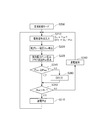
- FIG. 4 shows a flowchart in the initial temperature raising mode (M INT ).
- M INT initial temperature increase mode
- step S100 the initial temperature increase mode
- step S110 the step Proceeding to the heating element energization process of S120, energization of the heating element 10 is started.
- the plug resistance value calculation process in step S140 the plug resistance value R GP is calculated from the plug current I GP and the plug voltage V GP .
- the plug resistance value R GP is compared with the reference resistance value RC with respect to the target temperature in the initial state, and whether or not the reference resistance RC has been reached, that is, the heating element 10 It is determined whether or not the heat generation temperature has reached the target temperature.
- step S200 If the plug resistance value R GP is less than or equal to the reference resistance value RC , the determination is No, and the process returns to step S110 to maintain the initial temperature increase mode (M INT ). If the plug resistance value R GP is greater than the reference resistance value RC , the determination is Yes, the initial temperature rise mode (M INT ) is terminated, and the routine proceeds to the steady control mode in step S200.
- a preheating control mode ( MPRE ) in steps S121, S122, and S123 may be performed in order to prevent overheating.
- the reference resistance value slightly lower resistance than R C preheating target temperature, for example, a value corresponding to 1000 ° C.
- R C preheating target temperature
- R CH preheat control mode switching reference resistance value
- preheat control mode switching determination in step S121 fever in stroke compared with the plug resistance R GP preheating control mode changeover reference resistance value R CH, when the plug resistance R GP is below the preheating control mode switching reference resistance value R CH is determined No, early
- the process proceeds to an initial temperature raising mode maintenance process in step S123, and power exceeding the rating is applied with a duty of approximately 100%.
- the preheating control mode (M PRE ) control is performed by the on / off control so that the constant temperature is lower than the target temperature, for example, for a time of about 1 second.
- the preheating control mode M PRE can be performed by performing the processing according to the flow of steps S1221 to S1225.
- step S1221 it is determined whether or not a predetermined time tref has elapsed since the start of the preheating control mode. If the predetermined time has not elapsed (t ⁇ t ref ), the determination becomes Yes, and the process proceeds to the energization necessity determination process in step S1222, and the necessity of energization is determined by comparing R GP and R CH .
- step S1222 If R GP > R CH in step S1222, the determination is yes, and the process proceeds to step S1223, where energization is turned off. If R GP ⁇ R CH , the determination is no, the process proceeds to step S1224, and energization is turned on. Further, the process proceeds to a resistance value calculation process in step S1225, R GP is calculated again, and the process returns to step S1221 to repeat the loop. When a predetermined time elapses from the start of the preheating control mode, the preheating mode is terminated and the process proceeds to the main routine.
- the temperature is maintained at a target temperature, for example, about 250 ° C. lower than 1250 ° C. for a period of time, and then the temperature rising process (transition mode) to the steady control mode (M CST ) MTRN ) is prevented from overheating. Further, in the initial temperature raising mode (M INT ), the plug resistance value R GP changes every moment as the temperature rises, so the deterioration determination is not performed.
- the preheating control mode (M PRE ) is not limited to a single temperature.
- a plurality of preheating control modes may be provided such that the first preheating target temperature is 1000 ° C. and the second preheating target temperature is 1100 ° C. good.
- Information on the plug resistance R GP needs to be transmitted, and the amount of information increases, resulting in the same problem as in the prior art.
- the first preheating reference resistance and the second preheating resistance corresponding to each target temperature are processed so that they can be processed independently in the control module 20.
- the preheating reference resistance is prepared in the control module 20.
- the control unit-integrated glow plugs 1 (1 to n) provided for each cylinder are provided with independent energization control modules 20, and each glow plug 1 (1 to n).
- the heating elements 10 (1 to n) are independently energized, self-cylinder position determining means for detecting the own cylinder position and drive delay means for shifting the timing of energization start according to the cylinder position are provided. It is desirable to provide it.
- FIG. 5 shows a flowchart in the steady control mode.
- the stationary control mode in step S200 along with energization control in accordance with the reference resistance value R C of the individual heating elements 10 with power control in accordance with the drive signal SI is performed is performed, warning of abnormality by judging the deterioration state be able to.
- the steady control mode of step S200 is started, the input of the drive signal SI is detected in the drive signal input confirmation process of step S210, the process proceeds to the heating element energization process of step S220, and the heating element 10 is energized.
- step S220 the plug current I GP and the plug voltage V GP flowing in the heating element 10 are detected. Then the effective power plug resistance value calculation process of step S230, the effective power value P ACT and the plug resistance R GP is calculated from the plug current I GP and the plug voltage V GP.
- the presence or absence of deterioration is determined as a threshold value by comparing the effective power value PACT and the power threshold value PREF .
- the power threshold value P REF uses a degradation-time power value P WRN that has decreased to a certain value, for example, 90%, relative to the initial reference power value P INT in the initial state.
- step S240 the effective power value P ACT is higher than the power threshold value P REF is determined not to have deteriorated, the determination Yes, and the resistance value change reflecting unit step S250 (F / Proceed to step B).
- the effective power value P ACT is lower than the power threshold value P REF (e.g., when it becomes less than 90% of the initial reference power value P INT)
- determine that has deteriorated Thus, the determination is No, and the process proceeds to an abnormality diagnosis signal output process in step S260.
- the plug resistance value R GP is compared with the reference resistance value RC in order to feed back the change in the plug resistance value, and the plug resistance value R GP is used as the reference resistance value. If it exceeds RC , the determination becomes Yes, and the process proceeds to an energization stop process of Step 270. If the plug resistance value R GP is equal to or less than the reference resistance value RC , the determination is No, and the process proceeds to the energization maintenance process of Step 280.
- step S270 energization is stopped assuming that the heat generation temperature of the heating element 10 has reached the target value, and the process returns to step S210.
- step S280 energization is maintained assuming that the heat generation temperature of the heating element 10 has not reached the target value.
- step S210 By repeating step S210 to step S280, the energization is controlled, and the plug resistance value RGP close to the individual reference resistance value RC of each glow plug 1 (1 to n) is maintained.
- a self-diagnosis signal DI indicating a deterioration abnormality is output. For example, a warning lamp is lit to notify the driver of the deterioration abnormality, prompt replacement, or energize the heating element 10. A treatment according to necessity such as stopping is performed.
- the drive signal SI determines the duty ratio for determining the target temperature TTRG according to the driving situation, and rises according to the determination result of the necessity of energization detected by the resistance value change reflecting means 233 as described above.
- the MOS 21 is opened and closed in synchronization with the edge or the falling edge.
- the energization is performed at a duty according to SI (for example, 90% duty) until the end of energization of one pulse, and at the rise of the next drive signal SI.
- SI for example, 90% duty
- the reference resistor RC is used as a reference for switching between stopping and executing the energization of the heating element 10, but the MOS 21 is actually opened and closed. This is because, when the determination result (JDG) shown in FIG. 6C is in an off state, if the drive signal SI rises, the MOS 21 is turned off in synchronization with this, and the determination result (JDG) is on. If the drive signal SI falls in the state, the MOS 21 is turned on in synchronization therewith.
- the temperature change at that time is caused by the plug resistance R as shown in FIG. 6 (e).
- F / B control is performed in the control module 20 so as to make the plug resistance R GP coincide with the reference resistance RC in a self-contained manner, as in the conventional case.
- the temperature of the heating element 10 can be matched with the target temperature TTRG without using the engine water temperature or other temperature information.
- FIG. 7 shows a time chart in which the state from the initial state to the deteriorated state is arranged in time series in the steady control mode of the heat generating device to which the present invention is applied.
- the set driving signal SI corresponding to the target temperature T TRG is output.
- the heating element 10 gradually deteriorates with long-term use, and the resistance value R GP with respect to a constant heating temperature gradually increases.
- the reference resistance is started after energization is started in synchronization with the fall of the drive signal SI.
- the timing of exceeding RC gradually becomes earlier, and the maximum value of the resistance value RGP that rises in one cycle when energized at a constant duty ratio also increases. For this reason, in the deteriorated state, the time during which the plug resistance R GP is higher than the reference resistance RC becomes longer, and the number of times the MOS 21 is turned off increases as shown in FIG.
- the plug current I GP is lowered as shown in FIG. 7 (e), and the effective power P ACT is gradually lowered as shown in FIG. 7 (f).
- the effective power P ACT is deteriorated when the effective power P ACT changes more than a predetermined value relative to the initial reference power value P INT for the predetermined temperature in the initial state and becomes equal to or lower than the power threshold value P REF .
- the heat generation temperature T is maintained at the target temperature TTRG, and with the progress of deterioration, the heat generation temperature T decreases by ⁇ T or more and eventually becomes the deterioration limit temperature T WRN or less.
- the self-diagnosis signal DI indicating the deterioration abnormality is output.
- the reference resistance value RC and the initial reference power value P INT of each heating element 10 are stored in the MEM 232 at the time of manufacture, and based on these, the energization control and the deterioration abnormality determination are made, so the deterioration state of other glow plugs The temperature is accurately maintained without being affected by the deterioration, and a deterioration abnormality is warned at an appropriate time.
- the energization control method in the afterglow control mode will be described.
- the deterioration determination is performed in the steady control mode when performing so-called pre-glow control in which the control unit-integrated glow plug 1 is energized to assist ignition of the internal combustion engine.
- the deterioration determination of the control unit integrated glow plug of the present invention can be performed.
- the deterioration can be determined according to a flow almost similar to that in the steady control mode.
- the second deterioration current I WRN2 is used as a threshold for comparison with the plug current I GP.
- the resistance value change reflecting means (F / B process) in step S350 performs threshold determination by comparing with the second reference resistance value RC2 calculated from the plug resistance value RGP and the reference resistance value RC .
- the second degradation time of the power value P WRN2 and second reference resistance value R C2 in proportion thereto also low used.
- the deterioration determination of the glow plug is performed within a limited time immediately after the energization is stopped.
- the steady control mode and the after glow control mode are used. Since it is always performed during this period, it is possible to quickly detect and respond to deterioration abnormality.
- FIG. 9A is a characteristic diagram showing a temperature control state when the preheating control mode of the control unit integrated glow plug 1 of the present invention is not performed, and FIG. 9B is a case where the preheating control mode is performed.
- FIG. 9C is a characteristic diagram showing the temperature control state in the afterglow control mode.
- the temperature is raised quickly by substantially 100% duty or overpower supply, and further, the mode is lower than the first target temperature T 1.
- the switching temperature T CH switching from the early temperature increase control to the temperature increase suppression control is performed, so that the excessive temperature increase of the glow plug is suppressed, and after reaching the first target temperature, in the steady control mode.
- the energization control that is fed back to the drive signal is performed using the reference resistance RC according to the resistance temperature characteristic of the threshold as a threshold, the temperature is accurately maintained, the deterioration is always judged during the steady control mode period, and the deterioration abnormality is detected at an early stage
- the afterglow control mode the temperature can be accurately maintained at the second target temperature, and the deterioration abnormality is always determined during the afterglow control period. It is possible to perform the early deterioration anomaly detection in the.
- the preheating control mode M PRE when executed, as shown in FIG. 9B, the temperature is kept lower than the target temperature for a certain period of time, so that overheating is reliably prevented. , then, via a transition mode M TRN, shifts to the steady control mode M CST, is maintained at the target temperature. In this case, the deterioration determination is performed in a state where the temperature of either the preheating control mode M PRE or the steady control mode MCST is stable.
- the method of performing the deterioration determination simultaneously with the energization control in the steady control mode and the afterglow control mode has been described.
- disturbance due to the driving situation is excluded, and the presence or absence of deterioration is more accurately detected.
- a deterioration determination method for detection a method is shown in which the deterioration determination is performed either before cranking, immediately after the internal combustion engine is stopped, or at an idle stop.
- step S400 in the operation status confirmation process in step S400, for example, information indicating the operation status such as the engine speed NE is read, and in the deterioration determination availability determination process in step S410, the operation read in step S400. Based on the information indicating the situation, it is determined whether it is before cranking, immediately after the internal combustion engine is stopped, or at the time of idling stop.
- step S430 the process proceeds to the deterioration determination step in step S430, or before cranking, immediately after the internal combustion engine is stopped, or If it is not during idle stop, the determination is No, and the process returns to step S400 without performing deterioration determination.
- step S430 the plug current I GP flowing through the heating element 10, and a plug voltage V GP applied to the heating element 10, the effective power value P ACT is calculated, this The comparison is made with a predetermined power threshold value PREF .
- the above deterioration determination may always be performed on the glow plug side, and the operation state of the engine may be determined on the ECU side and selectively used.
- the semiconductor switching element 21 is an N-channel power MOSFET.
- the present invention is not limited to this, and a configuration in which a P-channel power MOSFET is provided on the high side may be used.
- the P-channel power MOSFET has a larger on-resistance than the N-channel MOSFET, but the drive circuit 22 does not need a gate voltage boosting means such as a charge pump.
- an N-channel power MOSFET may be provided on the downstream side of the load and driven to open and close by a low side driver.
- a voltage is applied to the glow plug other than during the operation, but it is not necessary to provide a boosting means such as a charge pump in the drive circuit unit 22, and the circuit can be simplified.
Landscapes
- Engineering & Computer Science (AREA)
- Chemical & Material Sciences (AREA)
- Combustion & Propulsion (AREA)
- Mechanical Engineering (AREA)
- General Engineering & Computer Science (AREA)
- Control Of Resistance Heating (AREA)
Abstract
通電により発熱する発熱体(10)と、その抵抗値RGPが目標抵抗値RTRGに一致するように通電制御する通電制御モジュール(20)とを有する発熱装置(1)であって、通電制御モジュール(20)とを略筒状のハウジング(30)内に一体的に収容すると共に、通電制御モジュール(20)が、所定の目標温度TTRGにおける抵抗値を基準抵抗値RCとして記憶する基準抵抗値記憶手段(232)と、通電時における発熱体(10)の抵抗値RGPが基準抵抗値RCを下回るときは通電を維持し、基準抵抗値RCを超えるときには通電を停止して発熱体(10)の温度変化に伴う抵抗値変化を通電制御に反映させる抵抗値変化反映手段(233)と、初期電力値PINTに対して所定の比率を掛けて算出される劣化時電力値PWRNを電力閾値PREFとして劣化判定する劣化判定手段(234)とを具備する。
Description
本発明は、通電により発熱すると共に、その抵抗値が自己の発熱温度に応じて正の相関をもって変化する発熱体と、電源からその発熱体への通電を制御する通電制御モジュールとを有する発熱装置に関し、簡易な構成により安定した通電制御と速やかな劣化異常検出とを実現し、特に、ディーゼル燃焼機関の気筒毎に設けたグロープラグを発熱体とし、発熱体と通電制御モジュールとが略筒状のハウジング内に一体的に収容された制御部一体型グロープラグに好適なものである。
従来、ディーゼル燃焼機関の着火を補助するグロープラグの断線異常や過電流異常等を検出する異常検出装置として、グロープラグとグロープラグへの通電を制御するスイッチ手段との間に電流センサやシャント抵抗等の電流検出手段を設けて、グロープラグに流れる電流とグロープラグに印加される電圧とから、グロープラグの抵抗値を算出し、グロープラグの劣化や断線異常を検出する装置が知られている。
特許文献1には、内燃機関を予熱するグロープラグへの通電により、前記グロープラグの抵抗に応じた検出値を検出する検出手段と、前記内燃機関の運転停止直後に、前記グロープラグに通電し、前記検出手段により検出した前記検出値に基づいて前記グロープラグの劣化を判定する判定手段とを備えたグロープラグ劣化判定装置が開示されている。
特許文献2には、ヒータに流れる電流を電圧に変換して第一電圧値を出力する第一電圧出力手段と、電源に接続されて、前記電源の電圧に対応する第二電圧値を出力する第二電圧出力手段と、前記第一電圧出力手段および前記第二電圧出力手段からそれぞれ出力される第一電圧値と第二電圧値とを比較することで、前記ヒータの劣化の有無を判別する比較判別手段とを備えたヒータ劣化検出装置が開示されている。
特許文献3には、通電によって発熱すると共に、自己の温度変化に応じて自己の抵抗値が正の相関をもって変化する発熱抵抗体を有するヒータについて、前記発熱抵抗体の抵抗値が目標抵抗値に一致するように通電を制御する抵抗値制御方式によって前記発熱抵抗体に対する通電を制御するヒータの通電制御装置であって、前記ヒータが取り付けられる内燃機関の駆動が停止されているときに、前記発熱抵抗体に通電して前記発熱抵抗体の第1抵抗値を取得する第1取得手段と、前記第1抵抗値を取得する際に、前記ヒータが使用される環境に応じた環境温度の情報を取得する環境情報取得手段と、前記第1抵抗値および前記環境温度の情報に基づいて、前記目標抵抗値を算出する算出手段と、前記内燃機関の駆動時に、前記算出手段によって算出された前記目標抵抗値に一致するように、前記発熱抵抗体への通電を制御する通電制御手段とを備えたことを特徴とするヒータの通電制御装置が開示されている。
特許文献1、2にあるような従来の劣化判定装置では、グロープラグに流れる電流を検出するための電流検出手段、及び、劣化を判定するための閾値を与える基準として、シャント抵抗等が用いられている。
また、グロープラグの抵抗値には不可避的に個体差が存在する。このため、一定の抵抗値を有するシャント抵抗を用いて検出したグロープラグに流れるプラグ電流と、グロープラグに印加された電圧とから算出された抵抗値と、一定の抵抗値を有する基準抵抗との比較によって劣化状態を閾値判定したのでは、グロープラグの抵抗値の個体差が無視されることになる。
例えば、初期抵抗が高いグロープラグの場合、使用に伴い僅かに抵抗値が上昇したときに、目標温度に到達させることが可能な状態で、実際には劣化していないにも拘わらず、検出される抵抗値が一定の閾値を超えた場合には、劣化していると誤って判定される虞があり、それとは逆に、初期抵抗値が低いグロープラグの場合、目標温度に到達できないほどに劣化しているにも拘わらず、元々の初期抵抗が低いために、使用に伴い抵抗値が上昇しても、一定の閾値を超えていない場合には、正常と誤って判定されたりする虞があった。
さらに、従来のグロープラグ通電制御装置においては、内燃機関の気筒毎に設けた複数のグロープラグへの通電を一つの通電制御装置によって制御している。このような構成において、それぞれのグロープラグの抵抗値には個体差があるので、過昇温を回避するためには、定格内で最も低い抵抗値のグロープラグを基準としてPWM制御により供給する平均電圧VAVGを決定し、VAVG
2/RGPで決まる電力が供給されることになる。
このため、複数のグロープラグの内、抵抗値の低いグロープラグの過昇温を回避できても、抵抗値の高いグロープラグの到達温度及び昇温速度の低下を招く虞もある。
このため、複数のグロープラグの内、抵抗値の低いグロープラグの過昇温を回避できても、抵抗値の高いグロープラグの到達温度及び昇温速度の低下を招く虞もある。
さらに、特許文献3にあるようなグロープラグ通電制御装置では、エンジン水温等の環境情報を利用しているので制御方法が複雑で、高い演算処理能力のCPUや割り込みタイマ等を必要とし、回路規模が大きくなり、装置の大型化が避けられず、様々な電子制御装置が高度に集約されたエンジンルーム内への搭載が困難となる虞がある。
加えて、従来のグロープラグ通電制御装置では、より精度良くグロープラグの発熱温度を制御したり、グロープラグの異常を検出したりするために、フロープラグ流れるプラグ電流やグロープラグに印加されるプラグ電圧をA/D変換してECU側に送信し、ECU側で演算処理を行ってグロープラグ通電制御装置の停止や温度補正に利用しており、グロープラグ通電制御装置とECUとの間で授受するデータ量が膨大となるため、高性能のCPUが必要となったり、CAN等の高速のデータ通信手段が必要となったりして、製造コストの増加が避けられなかった。
また、特許文献3にあるような方式により、一定の目標電力を印加したのでは、スワールの影響を受け、実際の発熱温度が目標温度より低下してしまうという大きな問題があった。
そこで、本発明は、かかる実情に鑑み、構成が極めて簡易で搭載性に優れ、しかも、同時に複数の発熱体が用いられる場合に、不可避的に存在する個々の発熱体の個体差に応じて精度良くそれぞれの劣化の有無を判定すると共に、各発熱体をそれぞれ独立して精度良く温度制御可能な制御部一体型発熱装置を提供することを目的とする。
そこで、本発明は、かかる実情に鑑み、構成が極めて簡易で搭載性に優れ、しかも、同時に複数の発熱体が用いられる場合に、不可避的に存在する個々の発熱体の個体差に応じて精度良くそれぞれの劣化の有無を判定すると共に、各発熱体をそれぞれ独立して精度良く温度制御可能な制御部一体型発熱装置を提供することを目的とする。
請求項1の発明では、通電により発熱すると共に、その抵抗値が自己の温度変化に応じて正の相関をもって変化する発熱体と、該発熱体の抵抗値が目標抵抗値に一致するように電源から上記発熱体への通電を制御する通電制御モジュールとを有する発熱装置であって、上記発熱体と上記通電制御モジュールとをハウジング内に一体的に収容すると共に、上記通電制御モジュールが、予め計測した所定の目標温度における上記発熱体の抵抗値を基準抵抗値として記憶する基準抵抗値記憶手段と、上記基準抵抗値を閾値として、通電時における上記発熱体の抵抗値が上記基準抵抗値を下回るときは通電を維持し、上記発熱体の抵抗値が上記基準抵抗値を超えるときには通電を停止して上記発熱体の温度変化に伴う抵抗値変化を通電制御に反映させる抵抗値変化反映手段と、を具備する。
請求項2の発明では、通電により発熱すると共に、その抵抗値が自己の温度変化に応じて正の相関をもって変化する発熱体と、該発熱体の抵抗値が目標抵抗値に一致するように電源から上記発熱体への通電を制御する通電制御モジュールとを有する発熱装置であって、上記発熱体と上記制御モジュールとをハウジング内に一体的に収容すると共に、上記通電制御モジュールが、予め計測した所定の目標温度における上記発熱体の抵抗値を基準抵抗値として記憶する基準抵抗値記憶手段と、上記基準抵抗値を閾値として、通電時における上記発熱体の抵抗値が上記基準抵抗値を下回るときは通電を維持し、上記発熱体の抵抗値が上記基準抵抗値を超えるときには通電を停止して上記発熱体の温度変化に伴う抵抗値変化を通電制御に反映させる抵抗値変化反映手段と、予め計測した所定の温度における定常状態での上記発熱体に印加される初期電力値に対して所定の比率を掛けて算出され、所定の劣化限界温度において上記発熱体に印加されると想定される劣化時電力値を閾値として劣化判定する劣化判定手段とを具備する。
請求項3の発明では、上記基準抵抗値を電気的トリミングによって調整可能な抵抗として設ける。
請求項4の発明では、上記電気的トリミングがツェナーザップ又はポリシリコンヒューズによるデジタルトリミングによって行われる。
請求項5の発明では、上記発熱体が内燃機関の気筒毎に設けたグロープラグである。
請求項6の発明では、上記劣化判定が内燃機関のクランキング前、内燃機関の停止直後、あるいはアイドルストップ時のいずれかで行われる。
請求項1の発明によれば、発熱体と通電制御モジュールとが一体となっており、製造段階で発熱体の抵抗値に個体差が生じていても、その個体差に応じて発熱装置毎に上記基準抵抗値を設定することができ、上記抵抗値変化反映手段によって温度変化に伴う抵抗値変化を通電制御に反映する際に他の発熱装置の状態に左右されることなく、独立して精度の高い温度制御が可能となる。
また、従来のように、エンジン水温などの外部からの情報を利用することなく、自己完結的に温度制御が可能であるため、構造を極めて簡素化することが可能で、製造コストの低減を図ることができる上に、搭載性にも優れている。
請求項2の発明によれば、請求項1の発明と同様の効果に加え、上記温度変化反映手段によって、発熱体の抵抗値を上記基準抵抗値に一致させるように温度制御が図られた場合に、長期の使用によって、発熱体の抵抗値が上昇すると、実効電力が小さくなり、実際の発熱温度が低くなったとしても、上記劣化判定手段によって、実効電力値が上記劣化時電力値以下となり、発熱温度が使用可能な限界温度以下となる虞があるときに劣化と判定することができ、従来のように外部環境情報等を利用したり、外部の演算処理装置等との間で多くの情報を交換したり、外部の演算処理装置によって劣化判定をしたりする必要がなく、簡易な構成により、自己完結的に劣化の有無を検出し、速やかに劣化異常に対する処置を図ることができる。
請求項3の発明によれば、通電制御モジュールを構成する素子の一部を利用して所望の基準抵抗値を形成することが可能となり、上記通電制御モジュールの体格を大きくすることがなく、高精度に温度制御が可能で、簡易な構成で劣化異常の有無を判定可能な制御部一体型発熱装置が実現できる。
請求項4の発明によれば、上記発熱体の個体差に応じた上記基準抵抗値をデジタルトリミングにより容易に精度良く調整することが可能となる。
請求項5の発明によれば、複数のグロープラグの間で個体差があっても、互いに影響されることなく、それぞれ独立して精度良く温度制御が可能で、しかも、速やかに劣化の有無を判定できるので極めて簡易な構成により、信頼性の高い制御部一体型グロープラグが実現できる。
請求項6の発明によれば、内燃機関の運転状態の影響を受けることなく、グロープラグの劣化判定を高精度に行うことが可能となる。
[規則91に基づく訂正 29.08.2012]
(a)は、本発明の実施形態における発熱装置の概要を示す構成図、(b)は、内燃機関の気筒毎に設けられた複数のグロープラグへの通電をそれぞれ独立して制御する制御部一体型グロープラグの全体概要を示す構成図である。
図1に示した制御部一体型グロープラグの構造を示し、(a)は図1に示した制御部一体型グロープラグの構造の縦断面図、(b)は本図(a)中A-Aに沿った横断面図、(c)は本発明を適用し得るグロープラグとして用いられる、いわゆるメタルヒータの概要を示す縦断面図、(d)は本発明を適用し得るグロープラグとして用いられる、いわゆるセラミックヒータの概要を示す縦断面図である。
本発明の適用されるグロープラグの温度とプラグ抵抗値との相関を示す特性図であって、RINTは、初期状態における抵抗温度特性(初期状態抵抗温度特性)を示し、RACTは、一定時間使用後の状態における抵抗温度特性を示し、RWRNは、劣化状態の抵抗温度特性を示す。
本発明の発熱装置に用いられる初期昇温制御方法を示すフローチャートである。
本発明の発熱装置に用いられる定常制御方法を示すフローチャートである。
本発明の適用される発熱装置のタイムチャートであって、(a)は本発明の適用される発熱装置における駆動信号を示すタイムチャート、(b)はプラグ抵抗の変化を示すタイムチャート、(c)は温度変化反映手段の判定結果を示すタイムチャート、(d)は温度変化をフィードバックした時の半導体開閉素子の作動状態を示すタイムチャート、(e)は通電電流の変化を示すタイムチャート、(f)は発熱温度の変化を示すタイムチャートである。
本発明の適用される発熱装置の定常制御モードにおいて、初期状態から劣化状態に至るまでを時系列に並べたタイムチャートであって、(a)は駆動信号を示すタイムチャート、(b)はプラグ抵抗の変化を示すタイムチャート、(c)は温度変化反映手段の判定結果を示すタイムチャート、(d)は温度変化をフィードバックした時の半導体開閉素子の作動状態を示すタイムチャート、(e)は通電電流の変化を示すタイムチャート、(f)は平均電力の変化を示すタイムチャート、(g)は発熱温度の変化を示すタイムチャートである。
本発明の発熱装置に用いられるアフターグロー制御方法を示すフローチャートである。
本発明の効果を示し、(a)は本発明の発熱装置での定常制御モードにおける温度制御状態を示す特性図、(b)は本発明の発熱装置での予熱制御モードにおける温度制御状態を示す特性図、(c)は本発明の発熱装置でのアフターグロー制御モードにおける温度制御状態を示す特性図である。
本発明の発熱装置での劣化判定の要否を決定するためのフローチャートである。
本発明の実施形態における発熱装置として、図略の内燃機関の気筒毎に設けた発熱体10を発熱体とし、電源6から発熱体10へ通電を制御する通電制御モジュール20とをハウジング30内に一体的に収容した制御部一体型グロープラグ1について説明する。
図1に示すように、本実施形態における制御部一体型グロープラグ1では、通電により発熱すると共に、その抵抗値が自己の温度変化に応じて正の相関をもって変化する発熱体10と、その抵抗値RGPが目標抵抗値RTRGに一致するように電源6から発熱体10への通電を制御する通電制御モジュール20と、発熱体10とを略筒状のハウジング30内に一体的に収容すると共に、通電制御モジュール20が、予め計測した所定の目標温度TTRGにおける発熱体10の抵抗値を基準抵抗値RCとして記憶する基準抵抗値記憶手段231と、基準抵抗値RCを閾値として、通電時における発熱体10の抵抗値RGPが基準抵抗値RCを下回るときは通電を維持し、基準抵抗値RCを超えるときには通電を停止して発熱体10の温度変化に伴う抵抗値変化を通電制御に反映させる抵抗値変化反映手段233を具備している。
さらに、通電制御モジュール20は、予め計測した所定の温度において定常状態で発熱体に印加される初期電力値PINTに対して所定の比率を掛けて算出され、所定の劣化限界温度TWRNにおいて発熱体10に印加されると想定される劣化時電力値PWRNを電力閾値PREFとして劣化判定する劣化判定手段234とを具備している。
本実施形態における劣化判定手段234は、発熱体10の抵抗値RGPを基準抵抗値RCに一致させるようにフィードバック制御した場合において、標温度TTRGの基準となる目標電力PTRGに対して、実際に発熱体10に流れるプラグ電流IGP及び発熱体10に印加されるプラグ電圧VGPの値から算出した実効電力値PACTが所定の劣化時電力値PWRN以下となった場合を劣化と判定し、自己診断信号DIを出力する自己診断手段とが設けられている。
具体的な劣化時電力値PWRNとして、製造時の目標温度TTRGを実現するのに必要とされる初期電力値PINTに対して、一定の割合(例えば、90%)を掛けた値を用いることができる。
具体的な劣化時電力値PWRNとして、製造時の目標温度TTRGを実現するのに必要とされる初期電力値PINTに対して、一定の割合(例えば、90%)を掛けた値を用いることができる。
図1を参照して本発明の実施形態における発熱装置として、図略の内燃機関8の気筒毎に設けられ通電により発熱する発熱体10(1~n)と、エンジン制御装置(ECU)7から、機関8の運転状況に応じた目標温度TTRGを決定するための駆動信号SIが出力され、駆動信号SIに同期して、電源6から発熱体10(1~n)への通電を基準抵抗RCと実際に検出されたプラグ抵抗RGPとの比較によって制御するための通電制御モジュール20(1~n)とが一体的ハウジング部30(1~n)内に収容されて構成され、コネクタ部40(1~n)内に収容されたコネクタ端子(41、42、43)を介してECU7に接続された制御部一体型グロープラグ1について説明する。
通電制御部モジュール20(1~n)は、少なくとも、半導体開閉素子21と、駆動回路部22と、発熱体制御IC23とがモールドパッケージ200内に収容され、電源入力端子201、駆動信号入力端子202、自己診断信号出力端子203、出力端子204、接地端子205の各端子が引き出されている。
本実施形態においては、半導体開閉素子21には、NチャンネルパワーMOSFETが用いられている(以下、適宜、MOS21と称す。)。
MOS21は、発熱体10に流れる大電流を開閉制御するため複数の制御用MOS210(以下、メインMOS210と称す。)を有しており、その一部を発熱体10に流れる電流を検出するための電流検出用MOS211(以下、センスMOS211と称す。)として用いており、メインMOS210とセンスMOS211とでカレントミラー回路を構成しており、センスMOS211に接続して電流検出用抵抗212が形成されている。
MOS21は、発熱体10に流れる大電流を開閉制御するため複数の制御用MOS210(以下、メインMOS210と称す。)を有しており、その一部を発熱体10に流れる電流を検出するための電流検出用MOS211(以下、センスMOS211と称す。)として用いており、メインMOS210とセンスMOS211とでカレントミラー回路を構成しており、センスMOS211に接続して電流検出用抵抗212が形成されている。
電流検出用抵抗212は、センス端子SENを介して本発明の要部である劣化判定手段234を備える発熱体制御IC23に接続されている。
駆動回路部(DRV)22は、本実施形態においては、例えばチャージポンプ等の昇圧手段を具備し、例えば、ECU7から機関8の運転状況に応じた目標温度TTRGを発熱させるためのデューティ比TON/Tを決定すべく出力された駆動信号SIの立ち下がりに同期して、MOS21を駆動すべく、所定の駆動電圧VGGに昇圧した電圧を出力する。
なお、後述するタイムチャートでは、図6、図7に示すように、駆動信号SIの立ち下がりに同期して通電を開始する例を示しているが、本発明において、駆動信号SIのHi、Loいずれの側でMOS21を駆動するかは適宜変更可能である。
チャージポンプは、例えば、オペアンプ220、チャージコンデンサ222、出力コンデンサ224、ダイオード221、223によって構成され、オペアンプ220のスイッチングにより、チャージコンデンサ222への電源電圧VBの充電と放電とを繰り返し、出力コンデンサ224に蓄えたエネルギを重畳して放電することにより、駆動電圧VGGとして電源電圧VBの2倍の電圧等に昇圧したゲート電圧VGGを通電制御用半導体素子21のゲート・ソース間に印加する。
さらに、図1(a)には、昇圧手段として、オペアンプ220と、ダイオード221、223と、コンデンサ222、224とによって構成されたチャージポンプを示したが、本発明において、昇圧方式を限定するものではなく、チョークコイル、コンデンサ、ダイオード等を組み合わせた、いわゆるチョッパ型のDC-DCコンバータや、昇圧トランス等を含むフライバック型のDC-DCコンバータ等を用いても良い。
本発明の要部である、発熱体制御IC23は、抵抗値演算手段230と、基準抵抗値記憶部(基準抵抗形成部)231と、基準抵抗調整手段(ツェナーザップ回路)232と、抵抗値変化反映手段(F/B手段)233と、初期電力基準抵抗と、初期電力基準抵抗調整手段(ツェナーザップ回路)と劣化判定手段234とによって構成されている。抵抗値演算手段230は、上述の電流検出用抵抗212によって検出されたプラグ電流IGPと、半導体開閉素子21から発熱体10に印加されるプラグ電圧VGP(半導体開閉素子21のソース電圧VSSに等しい。)とから、発熱体10のプラグ抵抗値RGPを算出する。
また、本実施形態においては、抵抗値RGPを算出の際の電流IGPをセンスMOS211により検出する例を示しているが、本発明において電流検出方法を限定するものではない。
例えば、MOS21がオフとなっている状態で、発熱体制御IC23側から発熱体10に数10mA~数100mAの比較的低い値で定電流を印加したときに発生するプラグ電圧VGPを検出することによって、より高い精度で発熱体10の抵抗値RGPを検出することができる。
例えば、MOS21がオフとなっている状態で、発熱体制御IC23側から発熱体10に数10mA~数100mAの比較的低い値で定電流を印加したときに発生するプラグ電圧VGPを検出することによって、より高い精度で発熱体10の抵抗値RGPを検出することができる。
発熱体10のプラグ抵抗値RGPは、発熱体10の固有の抵抗温度特性によって決まり、発熱体10の発熱温度とプラグ抵抗RGPとの間には一定の相関がある。
そこで、制御部一体型グロープラグ1の製造時、すなわち発熱体10と通電制御部モジュール20とを接続後に、発熱体10へ通電を行い、所定の目標温度(T1)に昇温させたときの抵抗値を外部の計測器により計測し、これを基準抵抗値RCとして基準抵抗値記憶部(基準抵抗形成部)231(以下、MEM231と称す。)に外部からの信号により記憶させる。
なお、発熱体10の製造時に、接続モジュール20を接続しない発熱体10の単体で抵抗値を測定し、その値を制御モジュール20のMEM231に記憶させるようにしても良い。
抵抗値変化反映手段(F/B手段)233は、MEM231に記憶した基準抵抗値RCと、実際に発熱体10が使用されているときに検出されたプラグ抵抗RGPとを比較し、その結果を駆動回路部22にフィードバックする。
発熱体10の発熱温度を個々の抵抗温度特性に応じた基準抵抗値RCに基づいて、基準抵抗値RCを維持するように、半導体開閉素子21を開閉して通電制御しているので、複数のグロープラグを一律の条件で通電制御する場合に比べて、より高い精度で所望の発熱温度に制御できる。
ところが、発熱体10は、長期にわたって使用を続けると、電極に使用している金属が絶縁体内へ拡散したり、発熱体と絶縁体との間で導電性成分が移動したりするマイグレーション等の現象を引き起こしたり、電極の剥離・酸化等により接触抵抗が増加したりしてプラグ抵抗RGPが上昇する。
そこで、目標温度TTRG(例えば、1250℃)から一定値ΔT(例えば、100℃)以上低下した劣化限界温度TWRN(例えば、1150℃)まで発熱温度が低下したときに劣化と判定する。
しかし、本発明の制御部一体型グロープラグ1では、実際の発熱温度を測定することなく、プラグ抵抗値RGPを基準抵抗値RCに一致させるように通電制御することにより温度制御するものであるから、実際の発熱体10の発熱温度によって劣化の有無を検出することができない。
また、電流値IGPはバッテリ電圧(電源電圧)+Bによって変化するので平均電流によって劣化判定することは精度を確保することができない。
そこで、目標温度TTRGとなるようにプラグ抵抗RGPが基準抵抗値RCと一致するように制御されているときの実効電力PACTの変化を、例えば、初期の目標温度TTRGにおける初期基準電力値PINTを電気的トリミングによって初期電力基準抵抗値RPINTとして記憶し、その値から一定以上変化し、所定の電力閾値PREF以下となったことを以って劣化と判断する。
そこで、目標温度TTRGとなるようにプラグ抵抗RGPが基準抵抗値RCと一致するように制御されているときの実効電力PACTの変化を、例えば、初期の目標温度TTRGにおける初期基準電力値PINTを電気的トリミングによって初期電力基準抵抗値RPINTとして記憶し、その値から一定以上変化し、所定の電力閾値PREF以下となったことを以って劣化と判断する。
本発明の特徴は、従来のように、発熱体10の抵抗値RGPを算出してこれを閾値判定して劣化判定を行なうのではなく、発熱体10の抵抗値RGPが一定の基準抵抗値RCと一致するように通電制御を行うことにより、発熱温度を一定に維持しようとしたときに、発熱体10の劣化に伴い、所定の温度に対する抵抗値RGPが上昇し、実効電力PACTが低下することを検出することによって劣化検出を行っている点にある。
この際の劣化判定の基準となる初期基準電力値PINTを記憶するためにトリミング可能な抵抗あるいはメモリ等の記憶素子を用いることにより、個体差に応じて高精度に劣化判定をすることが可能となっている。
具体的には、初期電力基準抵抗値RPINTを、基準抵抗調整手段232を用いて電気的トリミングによって調整可能な抵抗として設ける。
具体的には、初期電力基準抵抗値RPINTを、基準抵抗調整手段232を用いて電気的トリミングによって調整可能な抵抗として設ける。
さらに具体的には、電気的トリミングとしてツェナーザップ又はポリシリコンヒューズによるデジタルトリミングによって行う。
また、メモリを使って基準抵抗値RCを与えても良い。ただし、この場合にはマイコンが必要となり、回路規模が大幅に増大する点に留意すべきである。
また、メモリを使って基準抵抗値RCを与えても良い。ただし、この場合にはマイコンが必要となり、回路規模が大幅に増大する点に留意すべきである。
図2を参照して、本発明の発熱装置の実施形態における制御部一体型グロープラグ1の構造的な特徴について説明する。
制御部一体型グロープラグ1は、略筒状に形成したハウジング30と、その先端側に設けた発熱体10と、ハウジング内に収容された通電制御モジュール20と、外部との接続を図るコネクタ部40とが一体的に組み付けられた構造となっている。
制御部一体型グロープラグ1は、略筒状に形成したハウジング30と、その先端側に設けた発熱体10と、ハウジング内に収容された通電制御モジュール20と、外部との接続を図るコネクタ部40とが一体的に組み付けられた構造となっている。
本発明において、発熱体10は、図2(d)に示すようないわゆる、メタルヒータ10を用いても良いし、図2(e)に示すような、いわゆるセラミックヒータ10aを用いても良い。
メタルヒータ10は、基端側が開口し先端側が閉塞する略有底筒状の金属製保護管103の内側に、金属抵抗線コイルからなる発熱コイル102と制御コイル104とが直列に接続され、マグネシア粉末等の絶縁材料100と共に収容され、発熱コイル102の先端側に設けた接地部101において、金属製保護管103に電気的に接続され、制御コイル103の基端側で、通電制御モジュール20との導通を図る入力端子106が接続されている。発熱コイル102及び制御コイル103には、例えば、Fe-Cr-Al合金、Fe-Cr合金、Ni-Cr合金等の公知の抵抗材料が用いられ所定の比抵抗となるように形成されている。
セラミックヒータ10aは、略U字形に形成されたセラミック抵抗体102aと、セラミック抵抗体102aと外部との導通を図る一対のリード部103a、104aと、これらを覆い略柱状に形成された絶縁体100aとによって構成され、セラミック抵抗体102aの一方の端部に接続されたリード部103aの一端が絶縁体100aの側面方向に引き出され、接地端子101aが形成され、セラミック抵抗体102aの他方の端部に接続されたリード部104aの先端が、絶縁体100aの基端部に引き出され、入力端子105aが形成され、入力端子105aは、入力端子金具106aを介して通電制御モジュール20との導通が図られている。
セラミック抵抗体102aには、例えば、窒化珪素と、炭化タングステンの混合焼結体からなる導電性セラミック材料が用いられている。
セラミック抵抗体102aには、例えば、窒化珪素と、炭化タングステンの混合焼結体からなる導電性セラミック材料が用いられている。
また、リード部103a、104aには、タングステンなどの耐熱性金属材料が用いられている。
絶縁体100aには、窒化珪素等の絶縁性セラミック材料が用いられている。
メタルヒータ10又はセラミックヒータ10aは、略筒状の発熱体保持部材によって保持・固定されている。
絶縁体100aには、窒化珪素等の絶縁性セラミック材料が用いられている。
メタルヒータ10又はセラミックヒータ10aは、略筒状の発熱体保持部材によって保持・固定されている。
発熱体保持部材は、例えば、SUS(Stainless steel in Japanese Industrial Standards)等の金属材料からなり、略筒状に形成され、その内側にメタルヒータ10又はセラミックヒータ10aを保持、固定すると共に、金属製保護管103、又は、接地端子101aと電気的に接続され、発熱体10の一端がハウジング30を介してエンジンに接地状態となっている。
メタルヒータ10の場合、金属保護管103と発熱体保持部材とは、レーザ溶接、ロウ付け、ネジ締め等の公知の方法によって、互いに固定されている。
セラミックヒータ10aの場合、絶縁体100aと発熱体保持部材とは、嵌め合い、及び、ロウ付け等公知の方法によって固定されている。
セラミックヒータ10aの場合、絶縁体100aと発熱体保持部材とは、嵌め合い、及び、ロウ付け等公知の方法によって固定されている。
ハウジング30は、略筒状に形成されたハウジング基体300からなる。
ハウジング30の先端側には、発熱体保持部材を保持するための先端側筒状部が形成され、発熱体保持部材の基端側筒上部が挿嵌され、溶接等により固定されている。
ハウジング30の外周には、機関の燃焼室に螺結固定するためのネジ部303が形成されている。
ハウジング30の基端部には、内側に通電制御モジュール20を収容すると共に外部への接続を図るコネクタ部40が固定されている。
ハウジング30の基端側外周には、ネジ部303を螺結するための六角部304が形成されている。
ハウジング30の先端側には、発熱体保持部材を保持するための先端側筒状部が形成され、発熱体保持部材の基端側筒上部が挿嵌され、溶接等により固定されている。
ハウジング30の外周には、機関の燃焼室に螺結固定するためのネジ部303が形成されている。
ハウジング30の基端部には、内側に通電制御モジュール20を収容すると共に外部への接続を図るコネクタ部40が固定されている。
ハウジング30の基端側外周には、ネジ部303を螺結するための六角部304が形成されている。
コネクタ部40は、略筒状のカラーに覆われるようにしてハウジング30の基端側に固定されている。
コネクタ部40は、熱可塑性樹脂等を用いて略筒状に形成された樹脂成形部とその内側に固定され外部との接続を図るためのコネクタ端子41、42、43とによって構成されている。コネクタ部40の基端側には、略筒状に形成され、外部との接続を図る相手側コネクタと嵌合する嵌合部401が形成されている。コネクタ部40の中腹には、外部との接続を図るコネクタ端子41、42、43がインサート成型された端子固定部が形成されている。なお、外部との接続を図るコネクタ端子41、42、43は、それぞれ、電源入力用端子41、駆動信号入力用端子42、自己診断信号出力用端子43であるが、必要に応じてコネクタ端子の数を増減できる。
コネクタ部40は、熱可塑性樹脂等を用いて略筒状に形成された樹脂成形部とその内側に固定され外部との接続を図るためのコネクタ端子41、42、43とによって構成されている。コネクタ部40の基端側には、略筒状に形成され、外部との接続を図る相手側コネクタと嵌合する嵌合部401が形成されている。コネクタ部40の中腹には、外部との接続を図るコネクタ端子41、42、43がインサート成型された端子固定部が形成されている。なお、外部との接続を図るコネクタ端子41、42、43は、それぞれ、電源入力用端子41、駆動信号入力用端子42、自己診断信号出力用端子43であるが、必要に応じてコネクタ端子の数を増減できる。
例えば、基準抵抗値RCをツェナーザップトリミングによって抵抗値調整する場合のツェナーザップ用入力端子TZP1、TZP2と外部との接続を図るためのツェナーザップ用コネクタ端子を設けても良い。
なお、端子数を低減するため、これらのツェナーザップ用コネクタ端子は、駆動信号入力用端子42、自己診断信号出力用端子43あるいは電源入力用端子41と共通化しても良い。
コネクタ部40の先端側には、通電制御モジュール20を収容するための制御モジュール収容空間を区画する先端側隔壁部が形成されている。
コネクタ部40の先端側には、通電制御モジュール20を収容するための制御モジュール収容空間を区画する先端側隔壁部が形成されている。
図2(a)に示すように、電源入力用端子41、駆動信号入力用端子42、自己診断信号出力用端子43は、それぞれ、通電制御モジュール20の電源入力端子201、駆動信号入力端子202、自己診断信号出力端子203と接続されている。
さらに、通電制御モジュール20の出力端子204(ソース端子VSS)は、通電用中軸24を介して発熱体10、10aに接続され、GND端子205は、接地用ターミナル250を介してハウジング30に接続され、さらにハウジング30を介してエンジンに接地状態となっている。
本実施形態において、図1に示したように回路構成された通電制御モジュール20のMOS21、DRV22、JDG23等を、エポキシ樹脂等により、一体的に樹脂成形部200内に収容し、パッケージの外部にリードフレームを引き出して、電源入力端子41(BAT)、駆動信号入力用端子42(SI)、自己診断信号出力用端子43(DI)、出力端子204(VSS)、接地端子205(GND)が形成してある。
なお、図1においては、通電制御モジュール20を、いわゆるDIP型(Dual Inline Package型)のパッケージで表しているが、本発明において、通電制御モジュール20のパッケージ構造を限定するものではなく、いわゆるSIP型(Single Inline Package型)その他の公知のICパッケージに用いられる構造を適宜採用し得るものである。
なお、具体的には、グロープラグハウジング30内に実装するためには、パワーMOSFETと制御ICとを共に実装できる小型のディスクリート半導体素子用パッケージ、例えば、10mm×17mm×4.5mm程度の薄い樹脂モールドのパッケージの片方から、入力端子、グランド、出力端子の順に並んだ端子が引き出された、いわゆるTO-220型パッケージが望ましい。
ここで、図3を参照して本発明の制御部一体型グロープラグ1に用いられる発熱体10の温度特性について説明する。
本図は、定常状態、すなわち、発熱体にある電力を印加して、ある時間経過後にヒータ温度と抵抗値が飽和した状態におけるヒータ温度と発熱体の抵抗値との関係を示し、製造段階で確認される初期状態抵抗温度特性RINTを一点鎖線で示し、一定時間使用後の抵抗温度特性RACTを破線で示し、長期使用後の劣化状態における劣化時抵抗温度特性RWRNを実線で示している。
本図は、定常状態、すなわち、発熱体にある電力を印加して、ある時間経過後にヒータ温度と抵抗値が飽和した状態におけるヒータ温度と発熱体の抵抗値との関係を示し、製造段階で確認される初期状態抵抗温度特性RINTを一点鎖線で示し、一定時間使用後の抵抗温度特性RACTを破線で示し、長期使用後の劣化状態における劣化時抵抗温度特性RWRNを実線で示している。
本図に示すように、初期状態と劣化状態とでは、抵抗温度特性の傾きは変化せず、同一温度に対する抵抗値が高くなるように平行移動している。
このため、初期状態における目標温度TTRGに対する抵抗値を基準抵抗値RCとしたとき、基準抵抗値RCを維持しようと通電制御されると、発熱温度が低下することになり、許容限界温度TWRNまで低下した状態を劣化状態と判断し、異常警告等の処理を施す必要がある。
このため、初期状態における目標温度TTRGに対する抵抗値を基準抵抗値RCとしたとき、基準抵抗値RCを維持しようと通電制御されると、発熱温度が低下することになり、許容限界温度TWRNまで低下した状態を劣化状態と判断し、異常警告等の処理を施す必要がある。
図4、図5を参照して、本発明の制御部一体型グロープラグ1の通電制御方法並びに劣化判定方法について説明する。
図4に初期昇温モード(MINT)におけるフローチャートを示す。
キースイッチSWが入れられると、ステップS100の初期昇温モード(MINT)が開始され、ステップS110の駆動信号入力確認行程において、ECU30から出力された駆動信号SIの入力が検出されると、ステップS120の発熱体通電行程に進み、発熱体10への通電が開始される。
図4に初期昇温モード(MINT)におけるフローチャートを示す。
キースイッチSWが入れられると、ステップS100の初期昇温モード(MINT)が開始され、ステップS110の駆動信号入力確認行程において、ECU30から出力された駆動信号SIの入力が検出されると、ステップS120の発熱体通電行程に進み、発熱体10への通電が開始される。
次いでステップS130の電流・電圧検出行程においては、発熱体10に流れるプラグ電流IGP、プラグ電圧VGPが検出される。
次いでステップS140のプラグ抵抗値算出行程では、プラグ電流IGPとプラグ電圧VGPとからプラグ抵抗値RGPが算出される。
次いでステップS150のモード切換判定行程では、プラグ抵抗値RGPと初期状態における目標温度に対する基準抵抗値RCとを比較し、基準抵抗RCに到達しているか否か、即ち、発熱体10の発熱温度が目標温度に到達しているか否かが判定される。
次いでステップS140のプラグ抵抗値算出行程では、プラグ電流IGPとプラグ電圧VGPとからプラグ抵抗値RGPが算出される。
次いでステップS150のモード切換判定行程では、プラグ抵抗値RGPと初期状態における目標温度に対する基準抵抗値RCとを比較し、基準抵抗RCに到達しているか否か、即ち、発熱体10の発熱温度が目標温度に到達しているか否かが判定される。
プラグ抵抗値RGPが基準抵抗値RC以下の場合には判定Noとなり、ステップS110に戻り初期昇温モード(MINT)が維持される。
プラグ抵抗値RGPが基準抵抗値RCより大きくなった場合には判定Yesとなり、初期昇温モード(MINT)を終了し、ステップS200の定常制御モードに進む。
プラグ抵抗値RGPが基準抵抗値RCより大きくなった場合には判定Yesとなり、初期昇温モード(MINT)を終了し、ステップS200の定常制御モードに進む。
なお、ステップS120の発熱体通電行程において、過昇温を防止するため、S121、S122、S123による予熱制御モード(MPRE)を実施しても良い。
具体的には、基準抵抗値RCよりも僅かに低い抵抗値(予熱目標温度、例えば1000℃に相当する値)を予熱制御モード切換基準抵抗値RCHとし、ステップS121の予熱制御モード切換判定行程において、プラグ抵抗RGPと予熱制御モード切換基準抵抗値RCHとを比較し、プラグ抵抗RGPが予熱制御モード切換基準抵抗値RCH以下である場合には、判定Noとなり、早期に発熱体10を予熱目標温度に昇温すべく、ステップS123の初期昇温モード維持行程に進み、略100%のデューティで定格を超える電力を印加する。
具体的には、基準抵抗値RCよりも僅かに低い抵抗値(予熱目標温度、例えば1000℃に相当する値)を予熱制御モード切換基準抵抗値RCHとし、ステップS121の予熱制御モード切換判定行程において、プラグ抵抗RGPと予熱制御モード切換基準抵抗値RCHとを比較し、プラグ抵抗RGPが予熱制御モード切換基準抵抗値RCH以下である場合には、判定Noとなり、早期に発熱体10を予熱目標温度に昇温すべく、ステップS123の初期昇温モード維持行程に進み、略100%のデューティで定格を超える電力を印加する。
ステップS121の予熱制御モード切換判定行程において、プラグ抵抗RGPが予熱制御モード切換基準抵抗値RCHを超える場合には、判定Yesとなり、ステップS122の予熱制御モード(MPRE)に進み、予熱制御モード切換基準抵抗値RCHを閾値として、オンオフ制御により、例えば1秒程度の時間だけ、目標温度よりも低い定温度となるように予熱制御モード(MPRE)制御が行われる。
具体的には、例えばステップS1221~ステップS1225のフローに従った処理を実施することにより、予熱制御モードMPREを実施できる。
具体的には、例えばステップS1221~ステップS1225のフローに従った処理を実施することにより、予熱制御モードMPREを実施できる。
ステップS1221のタイムアップ判定行程において、予熱制御モード開始から一定時間tref経過したか否かが判定される。
一定時間経過前(t<tref)なら判定Yesとなり、ステップS1222の通電要否判定行程に進み、RGPとRCHとの比較により、通電の要否が判定される。
一定時間経過前(t<tref)なら判定Yesとなり、ステップS1222の通電要否判定行程に進み、RGPとRCHとの比較により、通電の要否が判定される。
ステップS1222でRGP>RCHなら判定Yesとなり、ステップS1223に進み、通電オフとなり、RGP≦RCHなら、判定Noとなり、ステップS1224に進み、通電オンとなる。さらに、ステップS1225の抵抗値算出行程に進み、再度RGPが算出され、ステップS1221に戻りループが繰り返される。
予熱制御モード開始から一定時間経過すると予熱モードを終了し、メインルーチンに移動する。
予熱制御モード開始から一定時間経過すると予熱モードを終了し、メインルーチンに移動する。
ステップS122の予熱制御モード(MPRE)では、目標温度、例えば1250℃よりも250℃程度低い温度にある時間保持されることでその後の定常制御モード(MCST)への昇温過程(遷移モードMTRN)での過昇温が抑制される。
また、初期昇温モード(MINT)においては、プラグ抵抗値RGPが温度上昇と共に刻々と変化するため、劣化判定は行わない。
また、初期昇温モード(MINT)においては、プラグ抵抗値RGPが温度上昇と共に刻々と変化するため、劣化判定は行わない。
なお、予熱制御モード(MPRE)は一つの温度だけでなく、例えば第1の予熱目標温度を1000℃、第2の予熱目標温度を1100℃というようにして複数の予熱制御モードを設けても良い。
この場合において、駆動信号SIのデューティ比を変えることによって、第1の予熱目標温度と第2の予熱目標温度とを切り換えることも可能であるが、そのような構成としたのでは、ECU7側にプラグ抵抗RGPの情報を送信することを要し、情報量が増大化し、従来と同様の問題を生じてしまうことになる。
この場合において、駆動信号SIのデューティ比を変えることによって、第1の予熱目標温度と第2の予熱目標温度とを切り換えることも可能であるが、そのような構成としたのでは、ECU7側にプラグ抵抗RGPの情報を送信することを要し、情報量が増大化し、従来と同様の問題を生じてしまうことになる。
そこで、本発明においては、このような複数の予熱制御モードを設けた場合においても、制御モジュール20内で独立して処理できるよう、それぞれの目標温度に応じた第1の予熱基準抵抗と第2の予熱基準抵抗とを制御モジュール20内に用意する。
予熱モードにおいて予熱目標温度が一つの場合と同様に、プラグ抵抗RGPとこれらの基準抵抗値との比較によって上述のステップS121又はステップS150と同様に通電の要否を判定し、プラグ抵抗RGPがそれぞれの基準抵抗値に一致するようにMOS21を開閉して通電制御を行うようにすれば、ECU7側の処理に頼ることなく制御モジュール20側で自己完結的に処理を行うことができる。
さらに、本発明において、電源に十分な容量が確保できる場合には必要ないが、複数の発熱体10(1~n)への通電が同時期に開始されると大きな突入電流が重なって電源6の負担が大きくなり、昇温速度が遅くなる場合がある。
そこで、本発明の発熱装置のように、気筒毎に設けた制御部一体型グロープラグ1(1~n)が、それぞれ独立の通電制御モジュール20を具備し、各グロープラグ1(1~n)の発熱体10(1~n)が独立して通電制御される場合においては、自己の気筒位置を検出する自己気筒位置判定手段及び、気筒位置に応じて通電開始のタイミングをずらす駆動遅延手段を設けるのが望ましい。
図5に定常制御モードにおけるフローチャートを示す。
ステップS200の定常制御モードでは、駆動信号SIにしたがって通電制御が行われると共に個々の発熱体10の基準抵抗値RCに応じた通電制御が行われると共に、劣化状態を判定して異常を警告することができる。
ステップS200の定常制御モードが開始されると、ステップS210の駆動信号入力確認行程で駆動信号SIの入力が検出され、ステップS220の発熱体通電行程に進み、発熱体10への通電が行われる。
ステップS200の定常制御モードでは、駆動信号SIにしたがって通電制御が行われると共に個々の発熱体10の基準抵抗値RCに応じた通電制御が行われると共に、劣化状態を判定して異常を警告することができる。
ステップS200の定常制御モードが開始されると、ステップS210の駆動信号入力確認行程で駆動信号SIの入力が検出され、ステップS220の発熱体通電行程に進み、発熱体10への通電が行われる。
ステップS220の電流・電圧検出行程においては、発熱体10に流れるプラグ電流IGP、プラグ電圧VGPが検出される。
次いでステップS230の実効電力・プラグ抵抗値算出行程では、プラグ電流IGPとプラグ電圧VGPとから実効電力値PACT及びプラグ抵抗値RGPが算出される。
次いでステップS230の実効電力・プラグ抵抗値算出行程では、プラグ電流IGPとプラグ電圧VGPとから実効電力値PACT及びプラグ抵抗値RGPが算出される。
次いでステップ240の劣化行程では、実効電力値PACTと電力閾値PREFとの比較によって劣化の有無が閾値判定される。
なお、電力閾値PREFは、初期状態における初期基準電力値PINTに対して一定以上、例えば、90%に低下した劣化時電力値PWRNを用いる。
なお、電力閾値PREFは、初期状態における初期基準電力値PINTに対して一定以上、例えば、90%に低下した劣化時電力値PWRNを用いる。
ステップS240の劣化判定行程において、実効電力値PACTが、電力閾値PREFよりも高い場合には、劣化していないものと判定され、判定Yesとなり、ステップS250の抵抗値変化反映手段(F/B行程)に進む。
ステップS240の劣化判定行程において、実効電力値PACTが電力閾値PREFよりも低い場合(例えば、初期基準電力値PINTの90%以下となった場合)には、劣化しているものと判定され、判定Noとなり、ステップS260の異常診断信号出力行程に進む。
ステップS240の劣化判定行程において、実効電力値PACTが電力閾値PREFよりも低い場合(例えば、初期基準電力値PINTの90%以下となった場合)には、劣化しているものと判定され、判定Noとなり、ステップS260の異常診断信号出力行程に進む。
ステップS250の抵抗値変化反映手段(F/B行程)では、プラグ抵抗値の変化をフィードバックするためプラグ抵抗値RGPと基準抵抗値RCとが比較され、プラグ抵抗値RGPが基準抵抗値RCを超える場合には判定Yesとなり、ステップ270の通電停止行程に進み、プラグ抵抗値RGPが基準抵抗値RC以下の場合には判定Noとなり、ステップ280の通電維持行程に進む。
ステップS270の通電停止行程では、発熱体10の発熱温度が目標値に到達しているものとして通電を停止し、ステップS210に戻る。
ステップS280の通電維持行程では、発熱体10の発熱温度が、目標値に到達していないものとして通電が維持される。
ステップS280の通電維持行程では、発熱体10の発熱温度が、目標値に到達していないものとして通電が維持される。
ステップS210からステップS280が繰り返されることにより、通電が制御され、各グロープラグ1(1~n)の個別の基準抵抗値RCに近いプラグ抵抗値RGPに維持される。
ステップS260の異常診断信号出力行程では、劣化異常を示す自己診断信号DIが出力され、例えば、警告灯を点灯して運転者に劣化異常を知らせ、交換を促したり、発熱体10への通電を停止したりする等の必要に応じた処置がなされる。
ステップS260の異常診断信号出力行程では、劣化異常を示す自己診断信号DIが出力され、例えば、警告灯を点灯して運転者に劣化異常を知らせ、交換を促したり、発熱体10への通電を停止したりする等の必要に応じた処置がなされる。
ここで、図6を参照して本発明の実施形態に係る発熱装置としての制御部一体型グロープラグ1の作動について説明する。なお、本図においては、予熱モードを実施しない場合の制御結果を示している。
駆動信号SIは、運転状況に応じた目標温度TTRGを決定するためのデューティ比を決定すると共に、上述の如く、抵抗値変化反映手段233によって検出された通電要否の判定結果にしたがって、立ち上がりエッジ、又は、立ち下がりエッジに同期してMOS21の開閉を切り換える。
駆動信号SIは、運転状況に応じた目標温度TTRGを決定するためのデューティ比を決定すると共に、上述の如く、抵抗値変化反映手段233によって検出された通電要否の判定結果にしたがって、立ち上がりエッジ、又は、立ち下がりエッジに同期してMOS21の開閉を切り換える。
図6(a)に示すようにECU7から駆動信号SIが入力されると、駆動信号SIの立ち下がりに同期して、図6(b)に示すように、発熱体10への通電が開始され、発熱温度が上昇する。
上述の如く、プラグ抵抗がRcを超えたときに、ステップS250の判定結果はYesとなり、このとき、図6(c)に示すように抵抗値変化反映手段233の出力を0とし、発熱体10への通電を行わないようにする。
上述の如く、プラグ抵抗がRcを超えたときに、ステップS250の判定結果はYesとなり、このとき、図6(c)に示すように抵抗値変化反映手段233の出力を0とし、発熱体10への通電を行わないようにする。
しかし、発熱体10への通電を直ちに遮断するのではなく、1パルスの通電が終わるまでは、SIに従ったデューティ(例えば90%デューティ)で通電を行い、次の駆動信号SIの立ち上がりで、MOS21を開いて発熱体10への通電を遮断し、プラグ抵抗が低下してRc以下となったら、ステップS250の判定結果はNoとなり、発熱体10への通電を再開させるよう、抵抗値変化反映手段233の出力を1とし、次の駆動信号SIの立ち下がりに同期してMOS21を閉じて発熱体10への通電を行う。
このように、本発明においては、図6(b)に示すように基準抵抗RCを発熱体10への通電の停止と実行とを切り替える基準に利用しているが、実際にMOS21が開閉されるのは、図6(c)に示す判定結果(JDG)がオフの状態の時に、駆動信号SIの立ち上がりがあると、これに同期してMOS21がオフとなり、判定結果(JDG)がオンの状態の時に駆動信号SIの立ち下がりがあると、これに同期してMOS21がオンとなる。
したがって、図6(d)に示すように、駆動信号SIの立ち上がり又は立ち下がりのエッジに同期して行われるので、その時の温度変化は、本図6(e)に示すように、プラグ抵抗RGPの変化から僅かに遅れて追従することになるが、制御モジュール20内で自己完結的にプラグ抵抗RGPを基準抵抗RCに一致させるようにF/B制御することで、従来のように、エンジン水温や他の温度情報を利用しなくても発熱体10の温度を目標温度TTRGに一致させることができる。
ここで、図7を参照して、本発明の発熱装置に用いられる劣化判定方向について説明する。
図7は、本発明の適用される発熱装置の定常制御モードにおいて、初期状態から劣化状態に至るまでを時系列に並べたタイムチャートを示している。
図7は、本発明の適用される発熱装置の定常制御モードにおいて、初期状態から劣化状態に至るまでを時系列に並べたタイムチャートを示している。
図7(a)に示すように、発熱体10の劣化状態に拘わらず、ECU7からは、目標温度TTRGに応じた設定された駆動信号SIが出力されている。
図3に示したように、発熱体10は長期の使用により、徐々に劣化し、一定の発熱温度に対する抵抗値RGPが徐々に上昇する。
図3に示したように、発熱体10は長期の使用により、徐々に劣化し、一定の発熱温度に対する抵抗値RGPが徐々に上昇する。
劣化の進行と共に発熱体10の抵抗値RGPが上昇すると、図7(b),図7(c)に示すように、駆動信号SIの立ち下がりに同期して通電を開始してから基準抵抗RCを超えるタイミングが徐々に早くなり、また、一定のデューティ比で通電したときに、一周期の間に上昇する抵抗値RGPの最大値も高くなる。
このため、劣化状態においては、プラグ抵抗RGPが基準抵抗RCよりも高くなる時間が長くなり、図7(d)に示すようにMOS21がオフとなる回数が多くなる。
このため、劣化状態においては、プラグ抵抗RGPが基準抵抗RCよりも高くなる時間が長くなり、図7(d)に示すようにMOS21がオフとなる回数が多くなる。
したがって、図7(e)に示すようにプラグ電流IGPは低くなり、図7(f)に示すように、実行電力PACTも徐々に低下することになる。
このとき、実効電力PACTが、予め計測した、初期状態における所定温度に対する初期基準電力値PINTに対して一定以上変化し、電力閾値PREF以下となった場合に劣化と判定される。
このとき、実効電力PACTが、予め計測した、初期状態における所定温度に対する初期基準電力値PINTに対して一定以上変化し、電力閾値PREF以下となった場合に劣化と判定される。
図7(e)に示すように、初期状態においては、発熱温度Tが目標温度TTRGに維持され、劣化の進行と共に、発熱温度TがΔT以上低下し、やがて劣化限界温度TWRN以下となり、上述の如く劣化異常を示す自己診断信号DIが出力される。
製造時において個々の発熱体10の基準抵抗値RC及び初期基準電力値PINTがMEM232に記憶され、これらに基づいて、通電制御並びに劣化異常判定がなされるため、他のグロープラグの劣化状態に影響されることなく正確に温度維持が図られ、適切な時期に劣化異常が警告されることになる。
製造時において個々の発熱体10の基準抵抗値RC及び初期基準電力値PINTがMEM232に記憶され、これらに基づいて、通電制御並びに劣化異常判定がなされるため、他のグロープラグの劣化状態に影響されることなく正確に温度維持が図られ、適切な時期に劣化異常が警告されることになる。
図8を参照して、アフターグロー制御モードにおける通電制御方法について説明する。
上記実施形態においては、内燃機関の着火を補助するために制御部一体型グロープラグ1への通電を行う、いわゆるプレグロー制御を行う際に定常制御モードにおいて劣化判定を行ったが、失火防止やエミッション低減を目的としたアフターグロー制御モードにおいても本発明の制御部一体型グロープラグの劣化判定を行うこともできる。
上記実施形態においては、内燃機関の着火を補助するために制御部一体型グロープラグ1への通電を行う、いわゆるプレグロー制御を行う際に定常制御モードにおいて劣化判定を行ったが、失火防止やエミッション低減を目的としたアフターグロー制御モードにおいても本発明の制御部一体型グロープラグの劣化判定を行うこともできる。
この場合において、定常制御モードとほぼ同様のフローに従って劣化判定することができるが、ステップS340の劣化判定行程において、プラグ電流IGPの比較対照とする閾値として、第2の劣化時電流IWRN2を用い、ステップS350の抵抗値変化反映手段(F/B行程)では、プラグ抵抗値RGPと基準抵抗値RCから算出した第2の基準抵抗値RC2と比較して閾値判定を行う。
アフターグロー制御モードにおいては、定常制御モードよりも目標温度が低くなるため、これに比例して第2の劣化時電力値PWRN2及び第2の基準抵抗値RC2も低い値が用いられる。
従来の劣化判定装置では、グロープラグの劣化判定は、通電停止直後の極限られた時間内に行われていたが、本発明の制御部一体型グロープラグ1では、定常制御モード及びアフターグロー制御モードの間常時実施されているので速やかに劣化異常を検出して対応することができる。
従来の劣化判定装置では、グロープラグの劣化判定は、通電停止直後の極限られた時間内に行われていたが、本発明の制御部一体型グロープラグ1では、定常制御モード及びアフターグロー制御モードの間常時実施されているので速やかに劣化異常を検出して対応することができる。
図9(a)は、本発明の制御部一体型グロープラグ1の予熱制御モードを実施しない場合の温度制御状態を示す特性図であり、図9(b)は、予熱制御モードを実施する場合の温度制御状態を示す特性図であり、図9(c)は、アフターグロー制御モードにおける温度制御状態を示す特性図である。
図9(a)に示すように、初期昇温モード(MINT)においては、略100%デューティ又は過電力供給によって早期に昇温を図り、さらに、第1の目標温度T1よりも低いモード切換温度TCHにおいて、早期昇温制御から昇温抑制制御に切換られるため、グロープラグの過昇温が抑制され、第1の目標温度に到達した後は、定常制御モードにおいて、個々のグロープラグの抵抗温度特性に応じた基準抵抗RCを閾値として、駆動信号にフィードバックした通電制御が行われるため正確に温度維持がなされ、定常制御モード期間中常時劣化判定が実施され早期に劣化異常が検出でき、アフターグロー制御モードにおいても第2の目標温度に正確に温度維持を図ることができる上に、アフターグロー制御期間中常時劣化異常判定を行うことで早期に劣化異常の検出を行うことができる。
なお、上述の如く、予熱制御モードMPREを実施する場合には、図9(b)に示すように、目標温度よりも低い温度で一定時間保持されることにより確実に過昇温が防止され、その後、遷移モードMTRNを経て、定常制御モードMCSTに移行し、目標温度に維持される。また、この場合において、劣化判定は、予熱制御モードMPRE及び定常制御モードMCSTのいずれかの温度が安定した状態で実施される。
図10を参照して、劣化検出を行うのにより望ましい時期とその判定方法について説明する。
上記実施形態においては、定常制御モード及びアフターグロー制御モードにおいて通電制御と同時に劣化判定を行う方法を示したが、本実施例においては、運転状況による外乱を排除し、より精度良く劣化の有無を検出するための劣化判定方法として、劣化判定をクランキング前、又は、内燃機関の停止直後、あるいはアイドルストップ時のいずれかにおいて実施する方法を示す。
上記実施形態においては、定常制御モード及びアフターグロー制御モードにおいて通電制御と同時に劣化判定を行う方法を示したが、本実施例においては、運転状況による外乱を排除し、より精度良く劣化の有無を検出するための劣化判定方法として、劣化判定をクランキング前、又は、内燃機関の停止直後、あるいはアイドルストップ時のいずれかにおいて実施する方法を示す。
例えば、クランキング時においては、スタータモータに大きな突入電流が流れ、バッテリ電圧の変動を伴う。このため発熱体10に流れる電流IGPがバッテリ電圧+Bの変動によって大きく変化するため、精度良くプラグ抵抗RGPを検出することが困難となる。また、エンジン運転時等においても、バッテリ電圧の変動を伴う虞があり、精度良くプラグ抵抗RGPを検出することが困難となる。
したがって、本発明の劣化判定は、内燃機関8のクランキング前、又は、内燃機関の停止直後、あるいはアイドルストップ時のいずれかで行うのが望ましい。
したがって、本発明の劣化判定は、内燃機関8のクランキング前、又は、内燃機関の停止直後、あるいはアイドルストップ時のいずれかで行うのが望ましい。
図10に示すように、ステップS400の運転状況確認行程において、例えば、エンジン回転数NE等の運転状況を示す情報が読み込まれ、ステップS410の劣化判定可否判定行程では、スッテップS400で読み込まれた運転状況を示す情報に基づいて、クランキング前、又は、内燃機関の停止直後、あるいはアイドルストップ時のいずれかであるかが判断される。
クランキング前、又は、内燃機関の停止直後、あるいはアイドルストップ時のいずれかである場合には判定Yesとなり、ステップS430の劣化判定行程に進み、クランキング前、又は、内燃機関の停止直後、あるいはアイドルストップ時のいずれでもない場合には、判定Noとなり、劣化判定を行うことなくステップS400に戻る。
ステップS430の劣化判定行程では、上記実施形態と同様、発熱体10に流れるプラグ電流IGPと、発熱体10に印加されるプラグ電圧VGPとから、実効電力値PACTが算出され、これを所定の電力閾値PREFと比較判定する。
なお上記劣化判定はグロープラグ側では常時実施し、ECU側でエンジンの運転状態を判定して選択的に使用してもよい。
なお、本実施形態においては、NチャンネルパワーMOSFETを負荷の上流側に配設し、ハイサイドドライバによって開閉駆動される例を示したが、本発明において、半導体開閉素子21は、NチャンネルパワーMOSFETに限定されるものではなく、PチャンネルパワーMOSFETをハイサイドに設けた構成でも良い。
一般に、PチャンネルパワーMOSFETは、NチャンネルMOSFETに比べて、オン抵抗が大きいことが知られているが、駆動回路22にチャージポンプ等のゲート電圧昇圧手段が不要となる。
なお、本実施形態においては、NチャンネルパワーMOSFETを負荷の上流側に配設し、ハイサイドドライバによって開閉駆動される例を示したが、本発明において、半導体開閉素子21は、NチャンネルパワーMOSFETに限定されるものではなく、PチャンネルパワーMOSFETをハイサイドに設けた構成でも良い。
一般に、PチャンネルパワーMOSFETは、NチャンネルMOSFETに比べて、オン抵抗が大きいことが知られているが、駆動回路22にチャージポンプ等のゲート電圧昇圧手段が不要となる。
また、NチャンネルパワーMOSFETを負荷の下流側に設けて、ローサイドドライバによって開閉駆動するようにしても良い。この場合は、グロープラグには動作中以外にも電圧が印加される問題があるが、駆動回路部22にチャージポンプ等の昇圧手段を設ける必要がなく、回路を簡素化できる。
1 制御部一体型グロープラグ(発熱装置)
10 グロープラグ(発熱体)
20 通電制御モジュール
200 モールドパッケージ
201 電源入力端子
202 駆動信号入力端子
203 自己診断信号出力端子
204 出力端子
205 接地端子
21 半導体開閉素子
210 制御用MOS
211 電流検出用MOS(ミラー回路部)
212 電流検出用抵抗(ツェナーザップ抵抗)
22 駆動回路部(DRV)
220 オペアンプ
221、223 ダイオード
222、224 コンデンサ
23 発熱体制御IC
230 抵抗値演算手段(電流・電圧検出部)
231 基準抵抗値記憶部(基準抵抗形成部)
232 基準抵抗調整手段(ツェナーザップ回路)
233 抵抗値変化反映手段(F/B手段)
234 劣化判定手段
30 ハウジング部
40 コネクタ部
41 電源入力用端子
42 駆動信号入力用端子
43 自己診断信号出力用端子
6 電源
7 エンジン制御装置(ECU)
8 内燃機関
SI 駆動信号
PACT 実効電力
PINT 初期基準電力値
PREF (劣化時の)電力閾値
PWRN 劣化時電力値
RC 基準抵抗値
RCH 予熱制御モード切換基準抵抗値
TZP1、TZP2 ツェナーザップ用入力端子
MINT 初期昇温モード
MPRE 予熱制御モード
MTRN 遷移モード
MCST 定常制御モード
Claims (6)
- 通電により発熱すると共に、その抵抗値が自己の温度変化に応じて正の相関をもって変化する発熱体(10)と、該発熱体(10)の抵抗値が目標抵抗値に一致するように電源から上記発熱体への通電を制御する通電制御モジュール(20)とを有する発熱装置(1)であって、
上記発熱体(10)と上記制御モジュール(20)とをハウジング(30)内に一体的に収容すると共に、
上記通電制御モジュール(20)が予め計測した所定の目標温度における上記発熱体(10)の抵抗値を、基準抵抗値として記憶する基準抵抗値記憶手段(231)と、
上記基準抵抗値を閾値として、通電時における上記発熱体(10)の抵抗値が上記基準抵抗値を下回るときは通電を維持し、上記発熱体(10)の抵抗値が上記基準抵抗値を超えるときには通電を停止して、上記発熱体(10)の温度変化に伴う抵抗値変化を通電制御に反映させる抵抗値変化反映手段(233)と、を具備することを特徴とする発熱装置(1)。 - 通電により発熱すると共に、その抵抗値が自己の温度変化に応じて正の相関をもって変化する発熱体(10)と、該発熱体(10)の抵抗値が目標抵抗値に一致するように電源から上記発熱体(10)への通電を制御する通電制御モジュール(20)とを有する発熱装置(1)であって、
上記発熱体(10)と上記通電制御モジュール(20)とをハウジング(30)内に一体的に収容すると共に、上記通電制御モジュール(20)が、予め計測した所定の目標温度における上記発熱体の抵抗値を基準抵抗値として記憶する基準抵抗値記憶手段(231)と、
上記基準抵抗値を閾値として、通電時における上記発熱体(10)の抵抗値が上記基準抵抗値を下回るときは通電を維持し、上記発熱体(10)の抵抗値が上記基準抵抗値を超えるときには通電を停止して上記発熱体(10)の温度変化に伴う抵抗値変化を通電制御に反映させる抵抗値変化反映手段(233)と、
予め計測した所定の温度における定常状態での上記発熱体(10)に印加される初期電力値に対して所定の比率を掛けて算出され、所定の劣化限界温度において上記発熱体(10)に印加されると想定される劣化時電力値を閾値として劣化判定する劣化判定手段(234)と、を具備することを特徴とする発熱装置(1)。 - 上記基準抵抗値を、電気的トリミングによって調整可能な抵抗として設けたことを特徴とする請求項1又は2に記載の発熱装置。
- 上記電気的トリミングが、ツェナーザップ又はポリシリコンヒューズによるデジタルトリミングによって行われることを特徴とする請求項3に記載の発熱装置。
- 上記発熱体(10)が内燃機関(8)の気筒毎に設けたグロープラグであることを特徴とする請求項1ないし4のいずれかに記載の発熱装置。
- 上記劣化判定手段(234)は、上記劣化判定を内燃機関(8)のクランキング前、内燃機関(8)の停止直後、あるいはアイドルストップ時のいずれかで実行することを特徴とする請求項2に記載の発熱装置。
Priority Applications (2)
| Application Number | Priority Date | Filing Date | Title |
|---|---|---|---|
| CN201280049575.1A CN103875308B (zh) | 2011-10-11 | 2012-08-24 | 发热装置 |
| EP12839896.3A EP2768276B1 (en) | 2011-10-11 | 2012-08-24 | Heating device |
Applications Claiming Priority (2)
| Application Number | Priority Date | Filing Date | Title |
|---|---|---|---|
| JP2011224286A JP5884390B2 (ja) | 2011-10-11 | 2011-10-11 | 発熱装置 |
| JP2011-224286 | 2011-10-11 |
Publications (1)
| Publication Number | Publication Date |
|---|---|
| WO2013054598A1 true WO2013054598A1 (ja) | 2013-04-18 |
Family
ID=48081658
Family Applications (1)
| Application Number | Title | Priority Date | Filing Date |
|---|---|---|---|
| PCT/JP2012/071378 WO2013054598A1 (ja) | 2011-10-11 | 2012-08-24 | 発熱装置 |
Country Status (4)
| Country | Link |
|---|---|
| EP (1) | EP2768276B1 (ja) |
| JP (1) | JP5884390B2 (ja) |
| CN (1) | CN103875308B (ja) |
| WO (1) | WO2013054598A1 (ja) |
Cited By (3)
| Publication number | Priority date | Publication date | Assignee | Title |
|---|---|---|---|---|
| EP2947310A1 (en) * | 2014-05-19 | 2015-11-25 | NGK Spark Plug Co., Ltd. | Energization control apparatus for a glow plug |
| US10280892B2 (en) * | 2017-04-27 | 2019-05-07 | Borgwarner Ludwigsburg Gmbh | Method for controlling the temperature of glow plugs |
| CN114578136A (zh) * | 2022-03-11 | 2022-06-03 | 辽宁省鑫源温控技术有限公司 | 一种电采暖负载异常的检测方法 |
Families Citing this family (10)
| Publication number | Priority date | Publication date | Assignee | Title |
|---|---|---|---|---|
| WO2012081448A1 (ja) * | 2010-12-16 | 2012-06-21 | ボッシュ株式会社 | グロープラグ駆動制御方法及びグロープラグ駆動制御装置 |
| DE102016109039A1 (de) * | 2016-02-17 | 2017-08-17 | Dbk David + Baader Gmbh | Elektrische Vorrichtung, insbesondere Heizer, sowie Vorrichtung und Verfahren zur Ansteuerung einer elektrischen Vorrichtung |
| JP6874719B2 (ja) * | 2018-03-02 | 2021-05-19 | オムロン株式会社 | 加熱装置及び加熱装置の異常検知方法 |
| JP2020035008A (ja) * | 2018-08-27 | 2020-03-05 | オムロン株式会社 | 温度制御システム、温度制御方法、およびプログラム |
| JP6988744B2 (ja) * | 2018-08-31 | 2022-01-05 | オムロン株式会社 | 温度制御システム、温度制御方法、およびプログラム |
| CN109900964B (zh) * | 2019-02-28 | 2021-10-22 | 深圳麦克韦尔科技有限公司 | 发热体的常温初始阻值标定方法和系统 |
| CN112649094B (zh) * | 2020-10-28 | 2022-12-02 | 深圳市吉迩科技有限公司 | 调温方法及气溶胶产生装置 |
| JP2022135161A (ja) * | 2021-03-04 | 2022-09-15 | オムロン株式会社 | 異常判定装置 |
| KR20240014484A (ko) * | 2021-07-09 | 2024-02-01 | 오므론 가부시키가이샤 | 이상 판정 장치, 이상 판정 방법 및 이상 판정 시스템 |
| TWI841942B (zh) * | 2021-07-09 | 2024-05-11 | 日商歐姆龍股份有限公司 | 異常判定裝置、異常判定方法以及異常判定系統 |
Citations (11)
| Publication number | Priority date | Publication date | Assignee | Title |
|---|---|---|---|---|
| JPS585476A (ja) * | 1981-06-30 | 1983-01-12 | Isuzu Motors Ltd | 急加熱グロ−プラグの制御装置 |
| JP2000502426A (ja) * | 1996-10-18 | 2000-02-29 | キャタピラー インコーポレイテッド | グロープラグの交流制御装置および方法 |
| JP2003240240A (ja) * | 2002-02-15 | 2003-08-27 | Denso Corp | グロープラグ |
| JP2004232907A (ja) * | 2003-01-29 | 2004-08-19 | Ngk Spark Plug Co Ltd | グロープラグ通電制御装置及びグロープラグ通電制御方法 |
| JP2006153293A (ja) * | 2004-11-25 | 2006-06-15 | Denso Corp | グロープラグ |
| JP2008064547A (ja) * | 2006-09-06 | 2008-03-21 | Sharp Corp | 光学式エンコーダ |
| JP2009036092A (ja) | 2007-08-01 | 2009-02-19 | Denso Corp | グロープラグ劣化判定装置 |
| JP2009191842A (ja) | 2008-01-15 | 2009-08-27 | Denso Corp | ヒータ劣化検出装置およびグロープラグ通電制御装置 |
| JP2009194187A (ja) * | 2008-02-15 | 2009-08-27 | Sharp Corp | ポリシリコンヒューズと、そのポリシリコンヒューズの製造方法、および、そのポリシリコンヒューズを用いた半導体装置と光電変換装置。 |
| JP2010065980A (ja) * | 2008-09-12 | 2010-03-25 | Ngk Spark Plug Co Ltd | ヒータ通電制御装置及びヒータ通電制御方法 |
| JP2010127487A (ja) | 2008-11-25 | 2010-06-10 | Ngk Spark Plug Co Ltd | ヒータの通電制御装置 |
Family Cites Families (4)
| Publication number | Priority date | Publication date | Assignee | Title |
|---|---|---|---|---|
| DE19944193A1 (de) * | 1999-09-15 | 2001-04-19 | Bosch Gmbh Robert | Glühstiftkerze |
| DE102006052634A1 (de) * | 2006-11-08 | 2008-05-15 | Robert Bosch Gmbh | Kraftstoffheizer |
| DE102008007397A1 (de) * | 2008-02-04 | 2009-08-06 | Robert Bosch Gmbh | Verfahren zur Überwachung von wenigstens einer Glühstiftkerze eines Brennkraftmotors und Vorrichtung hierzu |
| JP4956486B2 (ja) * | 2008-05-30 | 2012-06-20 | 日本特殊陶業株式会社 | グロープラグ通電制御装置及びグロープラグ通電制御システム |
-
2011
- 2011-10-11 JP JP2011224286A patent/JP5884390B2/ja active Active
-
2012
- 2012-08-24 WO PCT/JP2012/071378 patent/WO2013054598A1/ja active Application Filing
- 2012-08-24 EP EP12839896.3A patent/EP2768276B1/en active Active
- 2012-08-24 CN CN201280049575.1A patent/CN103875308B/zh not_active Expired - Fee Related
Patent Citations (11)
| Publication number | Priority date | Publication date | Assignee | Title |
|---|---|---|---|---|
| JPS585476A (ja) * | 1981-06-30 | 1983-01-12 | Isuzu Motors Ltd | 急加熱グロ−プラグの制御装置 |
| JP2000502426A (ja) * | 1996-10-18 | 2000-02-29 | キャタピラー インコーポレイテッド | グロープラグの交流制御装置および方法 |
| JP2003240240A (ja) * | 2002-02-15 | 2003-08-27 | Denso Corp | グロープラグ |
| JP2004232907A (ja) * | 2003-01-29 | 2004-08-19 | Ngk Spark Plug Co Ltd | グロープラグ通電制御装置及びグロープラグ通電制御方法 |
| JP2006153293A (ja) * | 2004-11-25 | 2006-06-15 | Denso Corp | グロープラグ |
| JP2008064547A (ja) * | 2006-09-06 | 2008-03-21 | Sharp Corp | 光学式エンコーダ |
| JP2009036092A (ja) | 2007-08-01 | 2009-02-19 | Denso Corp | グロープラグ劣化判定装置 |
| JP2009191842A (ja) | 2008-01-15 | 2009-08-27 | Denso Corp | ヒータ劣化検出装置およびグロープラグ通電制御装置 |
| JP2009194187A (ja) * | 2008-02-15 | 2009-08-27 | Sharp Corp | ポリシリコンヒューズと、そのポリシリコンヒューズの製造方法、および、そのポリシリコンヒューズを用いた半導体装置と光電変換装置。 |
| JP2010065980A (ja) * | 2008-09-12 | 2010-03-25 | Ngk Spark Plug Co Ltd | ヒータ通電制御装置及びヒータ通電制御方法 |
| JP2010127487A (ja) | 2008-11-25 | 2010-06-10 | Ngk Spark Plug Co Ltd | ヒータの通電制御装置 |
Non-Patent Citations (1)
| Title |
|---|
| See also references of EP2768276A4 * |
Cited By (3)
| Publication number | Priority date | Publication date | Assignee | Title |
|---|---|---|---|---|
| EP2947310A1 (en) * | 2014-05-19 | 2015-11-25 | NGK Spark Plug Co., Ltd. | Energization control apparatus for a glow plug |
| US10280892B2 (en) * | 2017-04-27 | 2019-05-07 | Borgwarner Ludwigsburg Gmbh | Method for controlling the temperature of glow plugs |
| CN114578136A (zh) * | 2022-03-11 | 2022-06-03 | 辽宁省鑫源温控技术有限公司 | 一种电采暖负载异常的检测方法 |
Also Published As
| Publication number | Publication date |
|---|---|
| EP2768276A1 (en) | 2014-08-20 |
| CN103875308A (zh) | 2014-06-18 |
| EP2768276B1 (en) | 2016-09-28 |
| JP5884390B2 (ja) | 2016-03-15 |
| EP2768276A4 (en) | 2015-07-01 |
| JP2013084478A (ja) | 2013-05-09 |
| CN103875308B (zh) | 2016-03-23 |
Similar Documents
| Publication | Publication Date | Title |
|---|---|---|
| WO2013054598A1 (ja) | 発熱装置 | |
| US8450982B2 (en) | Charge control circuit and charge controlling semiconductor integrated circuit | |
| US8644045B2 (en) | Temperature controlled voltage conversion device | |
| US20060049163A1 (en) | Controller of glow plug and glow plug | |
| WO2015080270A1 (ja) | 点火装置 | |
| JP4483587B2 (ja) | 多重放電点火システム | |
| EP1860752A1 (en) | Charging apparatus | |
| JPH099695A (ja) | 車両用電源装置 | |
| US9515584B2 (en) | Converter for an electric motor | |
| US20120085327A1 (en) | Internal-combustion-engine electronic control system | |
| JP2009038218A (ja) | 発光ダイオード駆動回路 | |
| US9850875B2 (en) | Ignition system and method for operating an ignition system | |
| JP5948740B2 (ja) | 制御部一体型グロープラグとその通電制御方法 | |
| JP5874052B2 (ja) | 電源装置、点灯装置、灯具、車両 | |
| US20160201637A1 (en) | Ignition device | |
| US10424902B2 (en) | Ignition device | |
| JP2008043015A (ja) | 熱電変換装置、熱電モジュールの制御方法 | |
| JP2005158870A (ja) | 負荷制御装置 | |
| KR100668599B1 (ko) | 디젤엔진의 예열플러그 제어장치 및 그 방법 | |
| JP4972035B2 (ja) | グロープラグ通電制御装置及びグロープラグ通電制御システム | |
| JP5540841B2 (ja) | グロープラグ通電制御装置 | |
| US8878385B2 (en) | Apparatus for controlling power supplied to discharge lamp in response to command supplied from outside the apparatus | |
| US10070506B2 (en) | Ignitor-arrangement | |
| JP2014165951A (ja) | 電流変更装置 | |
| JP2014025447A (ja) | グロープラグの通電制御装置及びグロープラグの通電制御方法 |
Legal Events
| Date | Code | Title | Description |
|---|---|---|---|
| WWE | Wipo information: entry into national phase |
Ref document number: 201280049575.1 Country of ref document: CN |
|
| 121 | Ep: the epo has been informed by wipo that ep was designated in this application |
Ref document number: 12839896 Country of ref document: EP Kind code of ref document: A1 |
|
| REEP | Request for entry into the european phase |
Ref document number: 2012839896 Country of ref document: EP |
|
| WWE | Wipo information: entry into national phase |
Ref document number: 2012839896 Country of ref document: EP |
|
| NENP | Non-entry into the national phase |
Ref country code: DE |