WO2013047278A1 - 医用画像処理装置、医用画像処理方法、プログラム - Google Patents
医用画像処理装置、医用画像処理方法、プログラム Download PDFInfo
- Publication number
- WO2013047278A1 WO2013047278A1 PCT/JP2012/073877 JP2012073877W WO2013047278A1 WO 2013047278 A1 WO2013047278 A1 WO 2013047278A1 JP 2012073877 W JP2012073877 W JP 2012073877W WO 2013047278 A1 WO2013047278 A1 WO 2013047278A1
- Authority
- WO
- WIPO (PCT)
- Prior art keywords
- image
- division
- tissue
- gray matter
- subject
- Prior art date
Links
Images


Classifications
-
- A—HUMAN NECESSITIES
- A61—MEDICAL OR VETERINARY SCIENCE; HYGIENE
- A61B—DIAGNOSIS; SURGERY; IDENTIFICATION
- A61B5/00—Measuring for diagnostic purposes; Identification of persons
- A61B5/0033—Features or image-related aspects of imaging apparatus classified in A61B5/00, e.g. for MRI, optical tomography or impedance tomography apparatus; arrangements of imaging apparatus in a room
- A61B5/004—Features or image-related aspects of imaging apparatus classified in A61B5/00, e.g. for MRI, optical tomography or impedance tomography apparatus; arrangements of imaging apparatus in a room adapted for image acquisition of a particular organ or body part
- A61B5/0042—Features or image-related aspects of imaging apparatus classified in A61B5/00, e.g. for MRI, optical tomography or impedance tomography apparatus; arrangements of imaging apparatus in a room adapted for image acquisition of a particular organ or body part for the brain
-
- A—HUMAN NECESSITIES
- A61—MEDICAL OR VETERINARY SCIENCE; HYGIENE
- A61B—DIAGNOSIS; SURGERY; IDENTIFICATION
- A61B5/00—Measuring for diagnostic purposes; Identification of persons
- A61B5/05—Detecting, measuring or recording for diagnosis by means of electric currents or magnetic fields; Measuring using microwaves or radio waves
- A61B5/055—Detecting, measuring or recording for diagnosis by means of electric currents or magnetic fields; Measuring using microwaves or radio waves involving electronic [EMR] or nuclear [NMR] magnetic resonance, e.g. magnetic resonance imaging
-
- G—PHYSICS
- G06—COMPUTING; CALCULATING OR COUNTING
- G06T—IMAGE DATA PROCESSING OR GENERATION, IN GENERAL
- G06T7/00—Image analysis
- G06T7/0002—Inspection of images, e.g. flaw detection
- G06T7/0012—Biomedical image inspection
- G06T7/0014—Biomedical image inspection using an image reference approach
-
- G—PHYSICS
- G06—COMPUTING; CALCULATING OR COUNTING
- G06T—IMAGE DATA PROCESSING OR GENERATION, IN GENERAL
- G06T2207/00—Indexing scheme for image analysis or image enhancement
- G06T2207/10—Image acquisition modality
- G06T2207/10072—Tomographic images
- G06T2207/10088—Magnetic resonance imaging [MRI]
-
- G—PHYSICS
- G06—COMPUTING; CALCULATING OR COUNTING
- G06T—IMAGE DATA PROCESSING OR GENERATION, IN GENERAL
- G06T2207/00—Indexing scheme for image analysis or image enhancement
- G06T2207/30—Subject of image; Context of image processing
- G06T2207/30004—Biomedical image processing
- G06T2207/30016—Brain
Definitions
- the present invention relates to a medical image processing apparatus or the like that performs diagnosis support for each disease by inputting a brain image captured by MRI (Magnetic Resonance Imaging) and performing image processing.
- MRI Magnetic Resonance Imaging
- VDRAD registered trademark
- the Z-score is a value indicating how many standard deviations are separated from the average value as a result of statistically comparing the subject image and the average image of healthy persons.
- the Z-score map like thermography, indicates the distribution of Z-scores by colors according to the values of the Z-scores, and displays them superimposed on the brain image of the subject. The Z-score map allows the diagnostician to visually confirm the degree of atrophy.
- the VBM is a technology that performs image processing on a brain image acquired by imaging the head of a subject, in units of voxels that are three-dimensional pixels.
- DARTEL is superior to the previous VBM in the accuracy of the processing of spatial standardization, and is expected as a technique for improving the diagnostic ability by image statistical analysis of Alzheimer's disease.
- the process of spatial standardization refers to a global correction to the size of the whole brain and a local to partial size in order to absorb the anatomical differences of the brain image existing among individuals. Correction is made.
- MRI brain images (especially T1-weighted MRI brain images) contain three types of tissues: gray gray matter corresponding to nerve cells, white matter corresponding to brighter nerve fibers, and cerebrospinal fluid near black. .
- DARTEL it is possible to accurately evaluate the degree of lesion or atrophy that is an abnormality of white matter extracted by tissue division from an MRI brain image of a subject (see Patent Document 2).
- division error in the process of tissue division, gray matter tissue and white matter tissue may not be accurately divided due to various reasons (hereinafter, such a case is referred to as "division error").
- VBM the old VBM was used, it was possible to easily determine that a division error has occurred by checking the Z score map. For example, in the case where a portion where the degree of atrophy is advanced in the Z-score map is red, if a division error occurs, the whole brain becomes red, including the region other than the vicinity of the hippocampus para-rotation. That is, it can be understood that the Z score was calculated as an abnormal value due to the division error, and it was possible to easily determine that the division error has occurred.
- the present invention has been made in view of the above-described problems, and it is an object of the present invention to provide a diagnostician that a division error may occur or a division error may occur in the process of tissue division. It is providing a medical image processing apparatus etc. which can be notified.
- an input means for inputting a subject's brain image
- a division means for performing tissue division processing on the subject's brain image to divide gray matter tissue
- health Diagnosis based on the statistical comparison between the memory means for storing the image group of the gray matter tissue of the person and the image of the gray matter tissue of the subject obtained by the dividing means and the image group of the gray matter tissue of the healthy person
- Output means for outputting support information, voxel values of the gray matter tissue according to the brain image of the subject, and statistical values for each voxel of the gray matter tissue according to the brain image group in which the tissue division processing is normally performed
- an identification unit that identifies whether the division result by the division unit is normal or not.
- the diagnostician it is possible to notify the diagnostician that a division error has occurred or a division error may have occurred in the process of tissue division.
- a division error since the segmentation result by tissue segmentation processing is automatically identified, no load is placed on the diagnostician.
- the discrimination means in the first invention compares the absolute Z score of the voxel value of the gray matter tissue according to the brain image of the subject with a predetermined threshold value, so that the division result by the division means is normal. It is desirable to identify whether or not. By this, it is possible to accurately identify the division result by the tissue division processing.
- the first invention further comprises warning means for outputting warning information when the identification means determines that the information is not normal.
- the diagnostician does not make a diagnosis without noticing the division error.
- the first invention preferably further comprises display means for displaying the division result by the division means when the identification means judges that the result is not normal. As a result, the diagnostician does not feel bothersome.
- an input step of inputting a subject's brain image a division step of performing tissue division processing on the subject's brain image to divide gray matter tissue, and the subject obtained by the division step.
- the identification step is provided.
- the diagnostician it is possible to notify the diagnostician that a division error has occurred or a division error may have occurred in the process of tissue division.
- a division error since the segmentation result by tissue segmentation processing is automatically identified, no load is placed on the diagnostician.
- a computer comprising: input means for inputting a brain image of a subject; division means for performing tissue division processing on the brain image of the subject; and dividing gray matter tissue; Outputting diagnostic support information on the basis of a statistical comparison between the image of the gray matter tissue of the subject obtained by the dividing means and the image group of the gray matter tissue of the healthy person, Based on output means, voxel values of the gray matter tissue according to a brain image of the subject, and statistical values for each voxel of the gray matter tissue according to a brain image group for which the tissue division processing has been normally performed. It is a program for functioning as an identification means which identifies whether the division result by the said division means is normal.
- the medical image processing apparatus of the first invention can be obtained by installing the program of the third invention on a general-purpose computer, and the medical image processing method of the second invention can be executed.
- a medical image processing apparatus etc. capable of notifying a diagnostician that a division error has occurred or a division error may have occurred in the process of tissue division.
- Block diagram showing an outline of a medical image processing apparatus Flow chart showing pre-processing of medical image processing method
- Normal example of tissue division result and division error example Flow chart showing tissue division result identification processing of medical image processing method
- Diagram showing the frequency distribution of the evaluation value and the threshold for each aspect of the division result Graph showing discrimination performance of segmentation error Chart showing sensitivity and specificity when the threshold is 0.8
- FIG. 1 is a block diagram showing an outline of a medical image processing apparatus.
- the medical image processing apparatus 1 is constructed by installing a program for causing a computer to execute the medical image processing method in the embodiment of the present invention. First, the hardware configuration of the computer will be described.
- the computer includes a control unit, a storage unit, a display unit, an input unit, an input / output interface (I / O), and the like.
- the control unit is a CPU (Central Processing Unit), ROM (Read Only Memory), RAM (Random Access Memory), etc.
- the CPU calls a program stored in a storage unit, a ROM, a recording medium or the like to a work memory area on the RAM and executes the program to drive and control each device, and realizes a process to be described later performed by a computer.
- the ROM is a non-volatile memory and permanently holds a computer boot program, a program such as a BIOS, data and the like.
- the RAM is a volatile memory, and temporarily stores programs, data and the like loaded from a storage unit, a ROM, a recording medium, etc., and includes a work area used by the control unit 21 to perform various processes.
- the storage unit is, for example, an HDD (Hard Disk Drive), and stores a program executed by the control unit, data necessary for program execution, an OS (Operating System), and the like.
- a control program corresponding to the OS and an application program for causing a computer to execute processing to be described later are stored.
- Each of these program codes is read by the control unit as needed, transferred to the RAM, read by the CPU, and executed as various means.
- the display unit includes a display device such as a liquid crystal panel, and a logic circuit (video adapter or the like) for realizing a video function of a computer in cooperation with the display device.
- the input unit inputs data, and includes, for example, an input device such as a keyboard, a pointing device such as a mouse, and a numeric keypad. Operation instructions, operation instructions, data input, and the like can be performed on the computer via the input unit.
- the display unit and the input unit may be integrated as in a touch panel display.
- the I / O is a port or the like for connecting a peripheral device (for example, a printer, a network device, etc.) to a computer.
- the computer transmits / receives data to / from peripheral devices via I / O. Further, the computer transmits / receives data to / from an imaging device (for example, an MRI or the like) of a medical image or a medical image management server or the like via a network device or the like.
- the medical image processing apparatus 1 includes a user interface unit 10, a processing unit 20, and a database unit 30.
- the user interface unit 10 has an image input function 11 for inputting an MRI image as an input image, and a result output function 12 for displaying the result processed by the processing unit 20.
- the processing unit 20 identifies whether the result of the image processing function 21 is normal or not, the image processing function 21 for processing the MRI image input from the user interface unit 10, the statistical processing function 22 for performing various statistical arithmetic processing and the like. And an identification processing function 23 for
- the medical image processing apparatus 1 includes (1) diagnosis support information output processing for outputting diagnosis support information based on an MRI brain image of a subject, and (2) images included in the diagnosis support information output processing.
- the diagnosis by the diagnostician is supported by performing an image processing result identification process that identifies whether the result of the process is normal or not and outputs the warning information if the result of the image process is not normal.
- FIG. 2 is a flowchart showing pre-processing of the medical image processing method.
- a template to be used in the spatial standardization of step 23 in the diagnostic support information generation processing of FIG. 3 is generated.
- the medical image processing apparatus 1 inputs T1-weighted MRI brain images (subject images in FIG. 2) relating to as many normal persons as possible.
- the MRI brain image acquired from each subject is preprocessed. Specifically, for example, 100 to 200 T1-weighted MRI images captured in slices of a predetermined thickness so as to include the entire brain of the subject are input. Further, the slice image is resampled in advance so that the lengths of the sides of the voxels in each slice image are equal to each other in advance.
- a voxel is a coordinate unit of an image having "thickness" and corresponds to a pixel in a two-dimensional image.
- the MRI brain image subjected to such pre-processing is input, it is checked whether the imaging direction and resolution of the slice image conform to the conditions set in the system in advance.
- the medical image processing apparatus 1 performs the spatial alignment process (step 11).
- the medical image processing apparatus 1 performs tissue division processing (step 12), extracts the white matter tissue and the gray matter tissue, and creates the white matter image and the gray matter image.
- tissue division processing is described as dividing white matter tissue and gray matter tissue, if the gray matter tissue can be correctly divided, the gray matter tissue of the subject obtained by the tissue division treatment is It is possible to output diagnosis support information based on a statistical comparison between an image and an image group of gray matter tissue of a healthy subject. Therefore, tissue division processing is sufficient if it at least divides gray matter tissue.
- the medical image processing apparatus 1 performs a process of extracting each of the white matter tissue and the gray matter tissue by paying attention to the difference between the signal values. This process is described in JP-A-2005-237441 (Patent Document 1). In the present embodiment, integrated tissue division processing is performed with higher extraction accuracy than the method performed in Patent Document 1.
- the integrated tissue segmentation process is a tissue segmentation method in which standardization, tissue segmentation, and correction of signal nonuniformity are incorporated into one model. For details, see “J.
- the integrated tissue division processing is characterized in that in addition to the white matter image and the gray matter image, a conversion field indicating the correspondence between the coordinates of the MRI image and the coordinates of the standard brain is created.
- the conversion site is used in the standardization described later.
- the medical image processing apparatus 1 acquires white matter images and gray matter images, in which white matter and gray matter are three-dimensionally extracted in advance, as a large number of samples by tissue division from MRI brain images of many healthy persons. Do.
- the medical image processing apparatus 1 divides the MRI brain images of a large number of healthy persons into tissue and creates white matter images from which white matter is extracted as samples, and spatial standardization among all created samples A white matter template is created according to (step 13). Similarly, the medical image processing apparatus 1 divides the MRI brain images of a large number of healthy persons into tissue and creates gray matter images from which gray matter is extracted as samples, and the gray matter is obtained by spatial standardization among all the samples. Create a template
- the medical image processing apparatus 1 creates a stratified template according to the attributes of the subject such as age and gender for each of the white matter and gray matter, and the white matter brain image template 31 in the database unit 30. , Save as gray matter brain image template 32.
- the medical image processing apparatus 1 performs the diagnostic support information creation process shown in FIG. 3 on the premise that the white and gray material templates created as described above are prepared for each age and gender.
- the white and gray templates will be referred to as Dartel templates.
- the medical image processing apparatus 1 inputs a subject image, and resamples the slice image so that the lengths of the sides of the voxels in the slice images become equal in advance. Then, the medical image processing apparatus 1 performs the process of spatial alignment in the same manner as in the case of step 11 in the pre-processing (step 21).
- the medical image processing apparatus 1 After the above spatial alignment is completed, the medical image processing apparatus 1 performs tissue division processing (step 22). This tissue division processing is the same as in the case of step 12 in the pre-processing.
- the medical image processing apparatus 1 extracts white matter and gray matter, and creates a white matter image and a gray matter image of the subject respectively.
- the medical image processing apparatus 1 performs processing of spatial standardization on the white matter image and gray matter image of the subject created as described above (step 23).
- the Dartell algorithm is applied to the spatial standardization performed here, as in step 13 in the pre-processing.
- the process of spatial standardization is a global correction to the size of the whole brain and a local correction to the partial size in order to absorb the anatomical differences of the brain images that exist between individuals. To do.
- the description will focus on gray matter, but substantially the same processing is performed in the case of white matter.
- Step 23 The process of spatial standardization in Dartel in step 23 is configured by the process of the following three steps.
- Step 23-1) Initial Position Determination Process
- Step 23-2) Conversion Process to Dartel Template
- Step 23-3) Conversion Process to Standard Brain Template
- the medical image processing apparatus 1 uses the conversion field to the standard brain obtained by the integrated tissue division process described above to perform an initial process on gray matter images and white matter images. Perform processing to determine the position. In this processing, since rigid body transformation is performed, it is a feature that the shape of the image does not change.
- the medical image processing apparatus 1 uses the Dartell algorithm to fit the shape of the image on which Step 23-1 is executed to the Dartell template.
- the medical image processing apparatus 1 performs a process for matching the image fitted to the Dartel template in step 23-2 to the standard brain template.
- the transformation field from the Dartell template to the standard brain template is obtained in advance, and transformation to the standard brain coordinate system is performed using the transformation field.
- step 23-2 and step 23-3 by performing normalization while holding the sum of signal values of each voxel, volume information is held, so that it is possible to measure the volume after standardization. .
- step 23-1 linear conversion is performed, and in steps 23-2 and 23-3, linear conversion and non-linear conversion are performed.
- the medical image processing apparatus 1 uses linear transformation and non-linear transformation to determine an error from the average gray matter brain image template 32 created in step 12 read from the database unit 30. Perform image processing to minimize the sum of squares of In this spatial standardization process, first, global correction of the position, size, and angle by linear conversion is performed, and then correction of the shape such as local unevenness is performed by nonlinear conversion.
- the linear transformation performed here is an affine transformation similar to the alignment in step 11.
- a deformation field representing local displacement is estimated in each of the x direction and the y direction, and the original image is transformed by this deformation field.
- the process of step 23-2 is a process of combining the image to be processed with the Dartel template created in step 13 as a template.
- the template used is sharp because it is created with high accuracy by applying the Dartell algorithm.
- the individual processing objects are adapted to a close form without individual differences by spatial standardization, the accuracy of spatial standardization can be improved, and the shapes among individuals become similar, but atrophy Etc. will be reflected in the local density.
- the medical image processing apparatus 1 performs three-dimensional convolution (convolution) of a three-dimensional brain image and a three-dimensional Gaussian function. This corresponds to sequentially performing one-dimensional convolution in the x, y, z directions. By performing smoothing in this manner, individual differences that do not completely match in the spatial standardization process can be reduced.
- step 23 brain volume information is stored. Therefore, before performing the next density value correction, the integral value of the region of interest (ROI: Regions Of Interest) described later is measured as a volume for the white and gray matter processing result images, and used as diagnosis support information. You may.
- ROI Regions Of Interest
- the voxel values of the whole brain are corrected in order to conform to the distribution of voxel values in the image group of a healthy person used as a standard when performing comparison later on the normalized brain image subjected to image smoothing as described above Perform density value correction.
- the medical image processing apparatus 1 performs statistical comparison with the healthy subject group (step 25).
- an MRI brain image of gray matter (white matter) of a subject who has been standardized through the respective processes of steps 21 to 24 above, and a healthy person who is collected in advance and stored in the database unit 30 as the healthy person image database 33 We perform comparison test with MRI brain image group of gray matter (white matter) of. It is desirable that the group of normal person images to be used be composed of those close to the subject's age.
- the medical image processing apparatus 1 performs a comparative test of 1: N (N is the total number of healthy person images) in a healthy person image group and voxel units, and a statistically significant difference is seen (abnormal Detect voxels (estimated).
- Z ( ⁇ -x) / ⁇ (1)
- Z Z score
- ⁇ average of corresponding voxel values of normal subject image group
- x voxel value of subject image
- ⁇ standard deviation of corresponding voxel value of normal subject image group.
- the Z score is a value obtained by scaling the difference between the voxel value of the subject image and the voxel value average of the corresponding voxel of the normal subject image group by the standard deviation, which is the gray matter (white matter) volume It indicates the degree of relative decline.
- the healthy person image database 33 used in step 25 is the spatial alignment of steps 21 to 24 ⁇ tissue division processing of gray matter (white matter) ⁇ space for each of a group of images of healthy persons separately collected in advance
- the respective processes such as dynamic standardization ⁇ image smoothing are sequentially performed to be similarly created and stored.
- these collected healthy person images are classified according to age, for example, every 5 years or every 10 years, and the storage unit stores the average value and standard deviation calculated for each group It is possible to perform a test by Z score by storing in.
- the medical image processing apparatus 1 performs ROI analysis (step 26).
- This is a method of setting a region of interest (ROI) of a predetermined size on an image when determining the presence or absence of an abnormality using a brain image, and on the brain image, it is noted that it is related to a specific disease.
- the comparison is performed by setting an ROI of a predetermined size at the specific site being processed.
- This analysis method is, as described in Patent Document 1, an ROI corresponding to a disease (vocal specific ROI 34) with respect to voxels of coordinate positions at which a significant difference is found with a healthy person by statistical processing and its Z score. To determine the degree of disease.
- the features are the following two points.
- An ROI (disease-specific ROI 34) is prepared as standardized image data corresponding to each disease of Alzheimer's disease, and each ROI is considered in the brain image data of the subject for the disease considered from the symptom of the subject. Is applied (set), and the most superior one based on the Z score in this ROI is taken as the diagnosis result.
- characteristics in the patient group having the disease A are obtained in advance, and the subject is determined to be the disease A when the values of the parameters of the subject match.
- diagnosis support information Such a determination result is output as diagnosis support information.
- the Z score and the value of each parameter are also output as diagnosis support information.
- a Z-score map that indicates the distribution of Z-scores by a color corresponding to the value of the Z-scores and is superimposed on the brain image of the subject is displayed as diagnosis support information.
- the diagnosis support information is displayed, for example, on the display unit of the medical image processing apparatus 1.
- the medical image processing apparatus 1 in the present embodiment executes an image processing result identification process (step 27) before outputting the diagnosis support information.
- the image processing result identification process will be described later with reference to FIG.
- the medical image processing apparatus 1 performs diagnosis support information output processing.
- the process of tissue division may cause a division error in which gray matter tissue and white matter tissue are not correctly divided due to various reasons.
- the processing results of the medical image processing apparatus 1 to which DARTEL is applied in most cases, even if the diagnostician visually checks the Z score map, it is not possible to determine whether or not a division error has occurred.
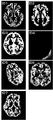
- FIG. 4 shows a normal example of tissue division results and a division error example.
- ID1 to ID7 are images of axial (cross-sectional) slices, and in each case, the site of gray matter is shown as white, and the other areas are shown as black.
- ID1 is a normal example
- ID2 to ID7 are division errors. There are various causes of the division error, such as the subject moving at the time of imaging, the imaging position being shifted, and the imaging condition being incorrect.
- Image with insufficient contrast of gray matter and white matter ⁇ Image with undesirable SN ratio (signal to noise ratio) (image with noticeable noise) ⁇ Image with signal unevenness ⁇ Image with artifact (due to magnetic susceptibility, body movement, aliasing, etc.) ⁇ Image with too wide imaging range ⁇ Image in which degeneration of tissue such as white matter infarction occurs in a wide area
- the image of ID2 contains a lot of white matter. This can be understood by observing in comparison with the image of ID1.
- image of ID2 in the tissue division processing, a portion that should originally be extracted as white matter is extracted as gray matter.
- the image of ID4 shows almost no gray matter. This can be understood by observing in comparison with the image of ID1.
- the portion that should originally be extracted as gray matter has been extracted as white matter and cerebrospinal fluid.
- the image of ID5 has a large deviation of the entire shape and position. This can be understood by observing in comparison with the image of ID1. In the image of ID5, it seems that the imaging position was incorrect.
- ID6 is extremely noisy and blurry. This can be understood by observing in comparison with the image of ID1. In the image of ID6, it seems that the imaging condition was incorrect.
- ID7 The image of ID7 is widespread and missing. This can be understood by observing in comparison with the image of ID1. In the image of ID7, it is assumed that the imaging range was incorrect or some imaging data were missing.
- the image processing result identification processing shown in FIG. 5 automatically identifies whether the division result as shown in FIG. 4 is normal or not, and a division error occurs. It provides a mechanism to notify the diagnostician if there is a possibility that a split error or division error has occurred.
- FIG. 5 is a flowchart showing tissue division result identification processing of the medical image processing method.
- the tissue division result identification process is performed before outputting the diagnostic support information (see step 27 in FIG. 3).
- the medical image processing apparatus 1 selects a gray matter image of a subject (hereinafter, also referred to as “target subject”) which is a target of the diagnosis support information creation process (step 31).
- the gray matter image selected in step 31 is, for example, an image of an axial (cross section) slice passing through the origin of the MNI (Montreal Neurological Institute) coordinate system. This image crosses the area around the hippocampus (region of interest in this embodiment).
- the gray matter image identified in step 31 is not limited to this example, and may be an image of another slice.
- the gray-quality image specified in step 31 is not limited to one, but may be plural.
- the medical image processing apparatus 1 smoothes the gray matter image of the subject identified in step 31 (step 32).
- the smoothing here is the same as the image smoothing process in step 24 of FIG.
- the smoothing in step 32 is performed using, for example, a three-dimensional Gaussian kernel.
- the FWHM (half width) of the filter used for this smoothing is about 8 mm.
- the smoothing in step 32 is a process for removing the fine structure of gray matter to a certain extent and for equalizing the smoothness of the image group and the image group registered in the tissue division normal image database 35.
- tissue division normal image database 35 an gray matter image (hereinafter also referred to as "tissue division normal image") in which the tissue division processing in step 22 of FIG. 3 has been normally executed is registered.
- the medical image processing apparatus 1 performs smoothing similar to the smoothing performed on the gray matter image of the subject in step 32 on the tissue division normal image, and then registers the tissue division normal image database 35.
- the medical image processing apparatus 1 calculates an evaluation value for the image smoothed in step 32 in accordance with a previously-defined evaluation function (step 33).
- the evaluation function include the following.
- the x-axis and the y-axis are axes constituting an axial (cross section).
- the z-axis is an axis perpendicular to the subject's body axis, ie, axial (cross-sectional).
- Input (x, y) is a voxel value of voxel (x, y) in the gray matter image of the target subject, with the position of the z axis fixed.
- input (x, y, z) is a voxel value of voxel (x, y, z) in the gray matter image of the target subject.
- the mean (x, y) is an average value for each voxel (x, y) of the image group registered in the tissue division normal image database 35 with the position of the z axis fixed.
- mean (x, y, z) is an average value for each voxel (x, y, z) of the image group registered in the tissue division normal image database 35.
- SD (x, y) is a standard deviation for each voxel (x, y) of the image group registered in the tissue division normal image database 35 with the position of the z axis fixed.
- mean (x, y, z) is a standard deviation for each voxel (x, y, z) of the image group registered in the tissue division normal image database 35.
- X is the number of voxels in the x-axis direction.
- Y is the number of voxels in the y-axis direction.
- Z is the number of voxels in the z-axis direction.
- the medical image processing apparatus 1 When using the evaluation functions based on the equations (4), (6) and (8), the medical image processing apparatus 1 specifies one slice of gray matter image of the subject in step 31. On the other hand, when using the evaluation function based on the equations (5), (7) and (9), the medical image processing apparatus 1 determines the number of sheets matching the value of Z (the number of voxels in the z-axis direction) in step 31 Identify as a gray matter image of the subject subject. Even when only one gray matter image of the subject is used, it is possible to identify the division result with high accuracy, as described later with reference to FIGS. 6 to 8.
- the tissue division normal image itself is not used. Therefore, instead of storing the voxel values of each tissue division normal image in the tissue division normal image database 35, statistical values for each voxel of the tissue division normal image group (for example, mean (x, y), mean ( It is also possible to store x, y, z), SD (x, y), SD (x, y, z), etc. In the latter case, since the tissue division normal image itself is not stored, medical information of each subject can be reliably protected.
- the medical image processing apparatus 1 compares the evaluation value calculated in step 33 with a predefined threshold to identify a division result (step 34).
- the definition method of the threshold will be described later with reference to FIGS. 6 to 8.
- the medical image processing apparatus 1 When the medical image processing apparatus 1 identifies that the division result is normal (“normal” at step 35), the user confirms that the identification result is correct and instructs to register via the input unit (step The voxel values of the gray matter image of the target subject (but the image after being smoothed in step 32) are registered in the tissue division normal image database 35 (step 37). That is, the medical image processing apparatus 1 reflects, on the tissue division normal image database 35, voxel values of gray matter tissue relating to the brain image of the subject identified as normal in step 34. On the other hand, when the user confirms that the identification result is not correct and instructs not to register via the input unit (“NO” in step 36), the medical image processing apparatus 1 ends the process.
- the medical image processing apparatus 1 registers the voxel value of the gray matter tissue of the target subject. In place of, the following process is performed. That is, the medical image processing apparatus 1 reflects the voxel value of the gray matter image of the target subject on the statistical value of each voxel of the tissue division normal image group which has already been stored. Then, the medical image processing apparatus 1 registers, in the tissue division normal image database 35, a statistical value in which the voxel value of the gray matter image of the target subject is reflected.
- the medical image processing apparatus 1 identifies that the division result is not normal (“not normal” in step 35), it warns that the division result is not normal (step 38).
- a warning means for example, it is conceivable to display a message that the division result is not normal on the display unit or to output by sound.
- the message that the division result is not normal “Check segment results!” (Please confirm the division result!) Or “Probable sgment error! "(there is a possibility of division error!) and the like.
- screens displaying these messages include a processing result display screen including a Z score map, a report output screen of diagnosis support information, and the like.
- the medical image processing apparatus 1 displays a division result display screen indicating the division result (step 39).
- a division result display screen indicating the division result
- an image before division, a white matter image, a cerebrospinal fluid image and the like are displayed on the division result display screen.
- the medical image processing apparatus 1 displays the division result display screen indicating the division result only when it is determined that the division result is not normal.
- the medical image processing apparatus 1 performs image processing result identification processing.
- the definition method of the threshold in FIG. 5 will be described with reference to FIGS. 6 to 8.
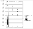
- FIG. 6 is a diagram showing the frequency distribution of evaluation values and the threshold for each aspect of the division result.
- FIG. 7 is a graph showing the discrimination performance of the division error.
- FIG. 8 is a diagram showing sensitivity and specificity when the threshold value is 0.8.
- FIGS. 6 to 8 each prepare a plurality of division results according to the normal example and the division error example shown in FIG. 4 and define the threshold.
- the number of data of each division result is as follows.
- the horizontal axis is an ID for identifying an aspect of the division result
- the vertical axis is an evaluation value calculated in step 33 of FIG. 5.
- the evaluation value shown in FIG. 6 is obtained by the evaluation function of equation (6).
- the plot of the example where the division result is normal is surrounded by a solid rectangle, and the division result is surrounded by the dotted rectangle.
- the identification is performed based on the threshold value of 0.8, and the identification result is regarded as an error if it is equal to or more than the threshold value, and the identification result is regarded as normal if it is less than the threshold value.
- the threshold value is defined as 0.8 in FIG. 6
- the horizontal axis is the evaluation value (or threshold)
- the vertical axis is the sensitivity / specificity.
- the sensitivity is a value defined as “probability of correctly determining one that should be determined as positive (in the present embodiment,“ the division result is not normal ”) as positive” for a certain test. “Sensitivity is high (high sensitivity)” means “it is likely to be correctly judged as positive to be judged positive” or “may be erroneously judged to be negative as to be judged positive” Means low.
- the specificity is a expression that is paired with the sensitivity, and as shown in FIG. 7, is determined by the balance with the sensitivity.
- the specificity is a value defined as “probability of correctly determining negative as to be negative (in this embodiment,“ division result is normal ”)” for a certain test.
- High specificity means that "what is to be judged as negative is likely to be correctly judged as negative", or "what is to be judged as negative is erroneously judged as positive. It means that the possibility is low.
- a division error occurs in the process of tissue division or division in order to eliminate the possibility of causing a serious misdiagnosis if the diagnosis is made without being aware of the division error.
- the purpose is to notify the diagnostician that an error may have occurred. Therefore, it is desirable to define the threshold value so as to have high sensitivity, that is, to set the value that should be determined as "the division result is not normal” to be correctly determined as "the division result is not normal”. .
- the threshold is 0.8.
- the medical image processing apparatus 1 can notify the diagnostician that a division error has occurred or a division error may have occurred in the tissue division process.
- the medical image processing apparatus 1 automatically identifies the division result by the tissue division processing, no load is placed on the diagnostician.
- the medical image processing apparatus 1 identifies that the division result by the tissue division processing is not normal, the warning information that the division error is generated or the division error may be generated together with the diagnostic support information. Because the diagnostician does not notice the division error, he / she does not make a diagnosis.
- the medical image processing apparatus 1 displays the division result display screen indicating the division result only when the division result by the tissue division processing is identified as not normal, the diagnostician does not feel bothersome .
- the medical image processing apparatus 1 stores voxel values of gray matter tissue or statistical values for each voxel in the tissue group normal image database 34 according to the brain image group for which the tissue division processing has been normally performed, Since the voxel values of the gray matter tissue related to the brain image of the identified subject are reflected in the tissue division normal image database 34, the accuracy of the process of calculating the evaluation value is improved, and hence the accuracy of the identification process is improved.
- the tissue division normal image database 35 collectively stores all data without considering the subject's attributes, imaging conditions, etc.
- the tissue division normal image database 35 includes the subject's It may be stored separately for each attribute or imaging condition.
- the attributes of the subject are, for example, gender and age.
- the imaging conditions are MRI model name, magnetic field strength, number of voxels, FOV (Field Of View) size, slice thickness, imaging time, TR (Repetition Time), TE (Echo Time), FA (Flip Angle), etc. .
- the medical image processing apparatus 1 divides and calculates the statistical value for each voxel for each attribute of the subject and the imaging condition. Then, when calculating the evaluation value in step 33 of FIG. 5, the medical image processing apparatus 1 evaluates the statistical value for each voxel according to the attribute of the target subject and the imaging condition when the brain image of the target subject is captured. Assign to a function
Abstract
【課題】組織分割の処理において分割エラーが生じている或いは分割エラーが生じている可能性があることを診断者に通知することが可能な医用画像処理装置等を提供する。 【解決手段】医用画像処理装置1は、対象被験者の灰白質画像を特定し(S31)、灰白質画像の平滑化を行い(S32)、例えば絶対Zスコアを算出するための評価関数に従って、評価値を算出する(S33)。次に、医用画像処理装置1は、評価値と予め定義された閾値とを比較し、分割結果を識別し(S34)、分割結果が正常ではないと識別した場合(S35の「正常ではない」)、分割結果が正常ではない旨を警告するとともに(S38)、分割結果を示す分割結果表示画面を表示する(S39)。
Description
本発明は、MRI(Magnetic Resonance Imaging)によって撮像された脳画像を入力し、画像処理を行うことにより、疾患別の診断支援を行う医用画像処理装置等に関するものである。
本発明者らは、早期AD(Alzheimer’s Disease)診断支援システムであるVSRAD(登録商標)(Voxel-Based Specific Regional Analysis System for Alzheimer’s
Disease)を開発している。VSRAD(登録商標)は、前駆期を含む早期アルツハイマー型認知症に特徴的にみられる海馬傍回付近(=関心領域)の萎縮の程度をMRI画像から読み取るための画像処理・統計解析ソフトウエアである。
Disease)を開発している。VSRAD(登録商標)は、前駆期を含む早期アルツハイマー型認知症に特徴的にみられる海馬傍回付近(=関心領域)の萎縮の程度をMRI画像から読み取るための画像処理・統計解析ソフトウエアである。
VSRAD(登録商標)では、関心領域の萎縮の程度を自動解析し、MRI脳画像にZスコアマップを重畳表示する。Zスコアとは、被験者画像と健常者平均画像を統計比較した結果、平均値からどれだけの標準偏差分離れているかを示す値である。Zスコアマップは、サーモグラフィのように、Zスコアの分布をZスコアの値に応じた色によって示し、被験者の脳画像に重ねて表示したものである。診断者は、Zスコアマップによって、萎縮の程度を視覚的に確認することができる。
VSRAD(登録商標)では、VBM(Voxel Based Morphometry)(特許文献1参照)やDARTEL(Diffeomorphic Anatomical Registration using Exponentiated Lie algebra)(特許文献2参照)といった技術を用いている。
VBMは、被験者の頭部を撮像して取得された脳画像を、3次元の画素であるボクセルを単位に画像処理を行う技術である。DARTELは、それまでのVBMに比べて、空間的標準化の処理の精度が優れており、アルツハイマー病の画像統計解析による診断能を向上させる技術として期待されている。ここで、空間的標準化の処理とは、個人の間に存在する脳画像の解剖学的な違いを吸収するために、脳全体の大きさに対する大局的な補正と、部分的な大きさに対する局所的な補正を行うものである。
MRI脳画像(特に、T1強調MRI脳画像)では、神経細胞に対応する灰色の灰白質、それより明るい神経線維に対応する白質、黒に近い脳脊髄液の3種類の組織が含まれている。DARTELを用いることによって、被験者のMRI脳画像から組織分割により抽出される白質の異常である病変や萎縮の程度を正確に評価することが可能となる(特許文献2参照)。
ところで、組織分割の処理は、様々な理由に起因して、灰白質組織と白質組織とが正確に分割されないことがある(以下、このような場合を「分割エラー」と称する。)。旧来のVBMを用いる場合、Zスコアマップを確認することによって、分割エラーが生じていることを容易に判別することが出来た。例えば、Zスコアマップにおいて、萎縮の程度が進んでいる箇所を赤色とする場合、分割エラーが生じていると、海馬傍回付近以外の領域も含めて、脳全体が赤色になる。つまり、分割エラーに起因してZスコアが異常な値として算出されたことが分かり、ひいては、分割エラーが生じていることを容易に判別することが出来た。
一方、DATELを用いる場合、旧来のVBMに比べると、空間的標準化の処理が非常に強力になっている為、分割エラーが生じていても、それらしいZスコアマップが表示されてしまう。つまり、分割エラーが生じていても、海馬傍回付近以外の領域も含めて、脳全体が赤色にならない場合がある。従って、DATELを用いる場合、Zスコアマップを確認しても、分割エラーが生じていることを判別することが難しい。そして、診断者が分割エラーに気付かずに診断を行ってしまうと、重大な誤診を招いてしまうという可能性があった。そこで、組織分割の処理において分割エラーが生じている或いは分割エラーが生じている可能性があることを診断者に通知する仕組みが望まれている。
本発明は、前述した問題点に鑑みてなされたもので、その目的とすることは、組織分割の処理において分割エラーが生じている或いは分割エラーが生じている可能性があることを診断者に通知することが可能な医用画像処理装置等を提供することである。
前述した目的を達成するために第1の発明は、被験者の脳画像を入力する入力手段と、前記被験者の脳画像に対して組織分割処理を行い、灰白質組織を分割する分割手段と、健常者の灰白質組織の画像群を保存する記憶手段と、前記分割手段により得られた前記被験者の灰白質組織の画像と前記健常者の灰白質組織の画像群との統計的比較に基づいて診断支援情報を出力する出力手段と、前記被験者の脳画像に係る前記灰白質組織のボクセル値と、前記組織分割処理が正常に行われた脳画像群に係る前記灰白質組織のボクセル毎の統計値とに基づいて、前記分割手段による分割結果が正常か否かを識別する識別手段と、を具備することを特徴とする医用画像処理装置である。第1の発明によって、組織分割の処理において分割エラーが生じている或いは分割エラーが生じている可能性があることを診断者に通知することが可能となる。特に、組織分割処理による分割結果を自動的に識別するので、診断者には全く負荷がかからない。
第1の発明における前記識別手段は、前記被験者の脳画像に係る前記灰白質組織のボクセル値の絶対Zスコアと、予め定義された閾値とを比較することによって、前記分割手段による分割結果が正常か否かを識別することが望ましい。これによって、組織分割処理による分割結果を精度良く識別することができる。
第1の発明は、前記組織分割処理が正常に行われた脳画像群に係る前記灰白質組織のボクセル値又はボクセル毎の統計値を記憶する記憶手段と、前記識別手段によって正常と識別された前記被験者の脳画像に係る前記灰白質組織のボクセル値を前記記憶手段に反映する反映手段と、を更に具備することが望ましい。これによって、評価値(絶対Zスコア)の算出処理の精度が向上し、ひいては、識別処理の精度が向上する。
第1の発明は、前記識別手段によって正常ではないと識別された場合、警告情報を出力する警告手段、を更に具備することが望ましい。これによって、診断者は、分割エラーに気付かずに診断を行ってしまうことがない。
第1の発明は、前記識別手段によって正常ではないと識別された場合、前記分割手段による分割結果を表示する表示手段、を更に具備することが望ましい。これによって、診断者は、煩わしさを感じることがない。
第2の発明は、被験者の脳画像を入力する入力ステップと、前記被験者の脳画像に対して組織分割処理を行い、灰白質組織を分割する分割ステップと、前記分割ステップにより得られた前記被験者の灰白質組織の画像と記憶手段に保存されている健常者の灰白質組織の画像群との統計的比較に基づいて診断支援情報を出力する出力ステップと、前記被験者の脳画像に係る前記灰白質組織のボクセル値と、前記組織分割処理が正常に行われた脳画像群に係る前記灰白質組織のボクセル毎の統計値とに基づいて、前記分割ステップによる分割結果が正常か否かを識別する識別ステップと、を含むことを特徴とする医用画像処理方法である。第2の発明によって、組織分割の処理において分割エラーが生じている或いは分割エラーが生じている可能性があることを診断者に通知することが可能となる。特に、組織分割処理による分割結果を自動的に識別するので、診断者には全く負荷がかからない。
第3の発明は、コンピュータを、被験者の脳画像を入力する入力手段と、前記被験者の脳画像に対して組織分割処理を行い、灰白質組織を分割する分割手段と、健常者の灰白質組織の画像群を保存する記憶手段と、前記分割手段により得られた前記被験者の灰白質組織の画像と前記健常者の灰白質組織の画像群との統計的比較に基づいて診断支援情報を出力する出力手段と、前記被験者の脳画像に係る前記灰白質組織のボクセル値と、前記組織分割処理が正常に行われた脳画像群に係る前記灰白質組織のボクセル毎の統計値とに基づいて、前記分割手段による分割結果が正常か否かを識別する識別手段と、して機能させるためのプログラムである。第3の発明のプログラムを汎用のコンピュータにインストールすることによって、第1の発明の医用画像処理装置を得ることができるとともに、第2の発明の医用画像処理方法を実行することができる。
本発明により、組織分割の処理において分割エラーが生じている或いは分割エラーが生じている可能性があることを診断者に通知することが可能な医用画像処理装置等を提供することができる。
以下図面に基づいて、本発明の実施形態を詳細に説明する。図1は、医用画像処理装置の概要を示すブロック図である。医用画像処理装置1は、コンピュータに、本発明の実施の形態における医用画像処理方法を実行させるためのプログラムがインストールされることによって構築される。最初に、コンピュータのハードウエア構成について説明する。
コンピュータは、制御部、記憶部、表示部、入力部、I/O(Input/Output interface)等を備える。制御部は、CPU(Central
Processing Unit)、ROM(Read Only Memory)、RAM(Random Access Memory)等から構成される。CPUは、記憶部、ROM、記録媒体等に格納されるプログラムをRAM上のワークメモリ領域に呼び出して実行し、各装置を駆動制御し、コンピュータが行う後述する処理を実現する。ROMは、不揮発性メモリであり、コンピュータのブートプログラムやBIOS等のプログラム、データ等を恒久的に保持している。RAMは、揮発性メモリであり、記憶部、ROM、記録媒体等からロードしたプログラム、データ等を一時的に保持するとともに、制御部21が各種処理を行う為に使用するワークエリアを備える。
Processing Unit)、ROM(Read Only Memory)、RAM(Random Access Memory)等から構成される。CPUは、記憶部、ROM、記録媒体等に格納されるプログラムをRAM上のワークメモリ領域に呼び出して実行し、各装置を駆動制御し、コンピュータが行う後述する処理を実現する。ROMは、不揮発性メモリであり、コンピュータのブートプログラムやBIOS等のプログラム、データ等を恒久的に保持している。RAMは、揮発性メモリであり、記憶部、ROM、記録媒体等からロードしたプログラム、データ等を一時的に保持するとともに、制御部21が各種処理を行う為に使用するワークエリアを備える。
記憶部は、例えば、HDD(Hard Disk Drive)であり、制御部が実行するプログラム、プログラム実行に必要なデータ、OS(Operating System)等が格納される。プログラムに関しては、OSに相当する制御プログラムや、後述する処理をコンピュータに実行させるためのアプリケーションプログラムが格納されている。これらの各プログラムコードは、制御部により必要に応じて読み出されてRAMに移され、CPUに読み出されて各種の手段として実行される。
表示部は、液晶パネル等のディスプレイ装置、ディスプレイ装置と連携してコンピュータのビデオ機能を実現するための論理回路等(ビデオアダプタ等)を有する。入力部は、データの入力を行い、例えば、キーボード、マウス等のポインティングデバイス、テンキー等の入力装置を有する。入力部を介して、コンピュータに対して、操作指示、動作指示、データ入力等を行うことができる。尚、表示部及び入力部は、タッチパネルディスプレイのように、一体となっていても良い。
I/Oは、コンピュータに周辺機器(例えば、プリンタ、ネットワーク機器等)を接続させるためのポート等である。コンピュータは、I/Oを介して周辺機器とのデータの送受信を行う。また、コンピュータは、ネットワーク機器等を介して、医用画像の撮像装置(例えば、MRI等)や医用画像管理サーバ等とのデータの送受信を行う。
次に、図1を参照しながら、医用画像処理装置1の機能について説明する。図1に示すように、医用画像処理装置1は、ユーザインタフェース部10、処理部20、及びデータベース部30を備えている。
ユーザインタフェース部10は、入力画像としてMRI画像を入力する画像入力機能11と、処理部20によって処理された結果を表示する結果出力機能12とを有する。
処理部20は、ユーザインタフェース部10から入力されたMRI画像を処理する画像処理機能21と、各種統計演算処理等を行う統計処理機能22と、画像処理機能21による結果が正常か否かを識別する識別処理機能23とを有する。
データベース部30には、処理部20による後述する処理に使用する白質脳画像テンプレート31、白質脳画像テンプレート32、健常者画像データベース33、疾患特異的ROI34、及び組織分割正常画像データベース35等が保存されている。
本実施形態における医用画像処理装置1は、(1)被験者のMRI脳画像を基に診断支援情報の出力等を行う診断支援情報出力処理、及び、(2)診断支援情報出力処理に含まれる画像処理の結果が正常か否かを識別し、画像処理の結果が正常ではない場合には警告情報の出力等を行う画像処理結果識別処理を行うことによって、診断者による診断を支援する。
以下では、診断支援情報出力処理の1例として、WO2011/040473号公報(特許文献2)に記載の第1実施形態を説明する。本実施の形態ではフローチャートのみを図に示し、処理の流れを説明する。
図2は、医用画像処理方法の事前処理を示すフローチャートである。図2の事前処理では、図3の診断支援情報作成処理におけるステップ23の空間的標準化において使用するテンプレートを作成する。
図2に示すように、医用画像処理装置1は、出来るだけ多くの健常者に係るT1強調MRI脳画像(図2では被験者画像)を入力する。
各被験者から取得したMRI脳画像については、前処理を行っておく。具体的には、被験者の脳全体を含むように所定の厚さのスライス状に撮像した、例えば100~200枚のT1強調MRI画像を入力とする。また、各スライス画像におけるボクセルの各辺の長さを予め等しくなるようにスライス画像のリサンプリングを行っておく。ここで、ボクセルは、「厚さ」を持つ画像の座標単位であり、2次元画像におけるピクセルに相当する。
このような前処理を行ったMRI脳画像を入力した後、そのスライス画像の撮像方向や解像度が、予めシステムに設定されている条件に適合しているか否かをチェックする。
以上のように、MRI脳画像が設定条件に適合して入力されていることが確認された場合には、医用画像処理装置1は、空間的位置合わせ処理を行う(ステップ11)。
これは、入力された脳画像を、標準的な脳画像と比較する際の精度を上げるために、アフィン変換によって空間的位置と角度の補正を行っていることに相当する。
以上の空間的位置合わせが終了した後、医用画像処理装置1は、組織分割処理を行い(ステップ12)、白質組織と灰白質組織とを各々抽出し、白質画像と灰白質画像を作成する。尚、本発明の実施の形態では、組織分割処理が白質組織と灰白質組織を分割するものとして説明するが、灰白質組織を正しく分割できれば、組織分割処理により得られた被験者の灰白質組織の画像と健常者の灰白質組織の画像群との統計的比較に基づいて診断支援情報を出力することが可能である。従って、組織分割処理は、少なくとも灰白質組織を分割するものであれば十分である。
入力されたT1強調MRI脳画像には、神経線維に対応する高い信号値を呈する白質、神経細胞に対応する中間の信号値を呈する灰白質、低い信号値を呈する脳脊髄液の3種類の組織が含まれている。そこで、医用画像処理装置1は、信号値の差に着目して白質組織と灰白質組織とを各々抽出する処理を行う。この処理については、特開2005-237441号公報(特許文献1)に説明されている。本実施の形態では、特許文献1において行っている手法よりも抽出精度が高い統合型組織分割処理を行う。統合型組織分割処理は、標準化、組織分割、信号不均一の補正を1つのモデルに組み込んだ組織分割手法である。詳しくは、「J.Ashburner and K. J. Friston. Unified segmentation. Neuro Image. 2005; 26: 839-851.」に記載されている。統合型組織分割処理では、白質画像および灰白質画像の他に、MRI画像の座標と標準脳の座標の対応関係を示す変換場が作成されるという特徴がある。変換場は後述する標準化において使用する。
このように、医用画像処理装置1は、予め多くの健常者のMRI脳画像から組織分割により、白質、灰白質が3次元的に抽出された白質画像、灰白質画像をそれぞれ多数のサンプルとして取得する。
以上のように、医用画像処理装置1は、多数の健常者のMRI脳画像をそれぞれ組織分割して白質が抽出された白質画像をサンプルとして作成し、作成された全てのサンプル間における空間的標準化により白質テンプレートを作成する(ステップ13)。同様に、医用画像処理装置1は、多数の健常者のMRI脳画像をそれぞれ組織分割して灰白質が抽出された灰白質画像をサンプルとして作成し、全てのサンプル間における空間的標準化により灰白質テンプレートを作成する。
ここで実行される空間的標準化には、ダーテル(DARTEL)・アルゴリズムが適用される。前述した通り、DARTELは、従来のVBMと比較して空間的標準化精度に優れており、アルツハイマー病の画像統計解析による診断能を向上させる技術として期待されている。また、DARTELの空間的標準化は従来の手法よりも精密に行われるため、灰白質だけではなく、白質をも評価対象とすることができる。
ステップ13のテンプレート作成処理では、医用画像処理装置1は、白質と灰白質それぞれについて、年齢や性別などの被験者の属性に応じた層別のテンプレートを作成し、データベース部30に白質脳画像テンプレート31、灰白質脳画像テンプレート32として保存する。
以上のようにして作成された白質と灰白質のテンプレートが、年齢別、性別毎に用意されていることを前提として、医用画像処理装置1は、図3に示す診断支援情報作成処理を行う。尚、以下では、白質と灰白質のテンプレートのことをダーテルテンプレートと呼ぶことにする。
図3は、医用画像処理方法の診断支援情報作成処理を示すフローチャートである。図3に示すように、診断支援情報作成処理では、診断対象の被験者に係るT1強調MRI脳画像を入力データとする。
図2の事前処理と同様、医用画像処理装置1は、被験者画像を入力し、各スライス画像におけるボクセルの各辺の長さを予め等しくなるようにスライス画像のリサンプリングを行う。そして、医用画像処理装置1は、空間的位置合わせの処理を、事前処理におけるステップ11の場合と同様に行う(ステップ21)。
以上の空間的位置合わせが終了した後、医用画像処理装置1は、組織分割処理を行う(ステップ22)。この組織分割処理は、事前処理におけるステップ12の場合と同様である。医用画像処理装置1は、白質と灰白質を抽出し、被験者の白質画像と灰白質画像をそれぞれ作成する。
以上のように作成された被験者の白質画像と灰白質画像に対して、医用画像処理装置1は、空間的標準化の処理を行う(ステップ23)。ここで行う空間的標準化には、事前処理におけるステップ13の場合と同様に、ダーテル・アルゴリズムが適用される。
この空間的標準化の処理は、個人の間に存在する脳画像の解剖学的な違いを吸収するために、脳全体の大きさに対する大局的な補正と、部分的な大きさに対する局所的な補正を行うものである。以下、便宜上、灰白質を中心に説明するが、白質の場合も実質的に同一の処理を行う。
ステップ23のダーテルでの空間的標準化の処理は、次の3つのステップの処理によって構成されている。
(ステップ23-1)初期位置決定処理
(ステップ23-2)ダーテルテンプレートへの変換処理
(ステップ23-3)標準脳テンプレートへの変換処理
(ステップ23-1)初期位置決定処理
(ステップ23-2)ダーテルテンプレートへの変換処理
(ステップ23-3)標準脳テンプレートへの変換処理
ステップ23-1の初期位置決定処理では、医用画像処理装置1は、前述した統合型組織分割処理によって得られる標準脳への変換場を使用して、灰白質画像、白質画像に対して、初期位置を決める処理を行う。この処理では、剛体変換を行うので、画像の形状は変わらないのが特徴である。
ステップ23-2のダーテルテンプレートへの変換処理では、医用画像処理装置1は、ステップ23-1が実行された画像に対して、ダーテル・アルゴリズムを用いて、ダーテルテンプレートに形状を合わせ込む。
ステップ23-2の標準脳テンプレートへの変換処理では、医用画像処理装置1は、ステップ23-2においてダーテルテンプレートに合わせ込まれた画像を、標準脳テンプレートに合わせ込む処理を行う。ダーテルテンプレートから標準脳テンプレートへの変換場を予め求めておき、その変換場を用いて標準脳座標系への変換を行う。
ステップ23-2とステップ23-3の処理では、各ボクセルの信号値の合計を保持したまま標準化を行うことによって、体積の情報が保持される為、標準化後に体積を計測することが可能となる。
ステップ23-1では線形変換、ステップ23-2及びステップ23-3では線形変換と非線形変換が行われる。ステップ23-2を例として説明すると、医用画像処理装置1は、線形変換と非線形変換を用いて、データベース部30から読み出したステップ12において作成された平均的な灰白質脳画像テンプレート32との誤差の平方和が最小になるように画像処理を行う。この空間的標準化処理では、初めに線形変換による位置や大きさ、角度の大局的な補正を行い、次に非線形変換によって局所的な凹凸等の形状の補正を行う。
ここで行われる線形変換は、ステップ11の位置合わせと同様のアフィン変換である。また、非線形変換は、x方向、y方向それぞれについて局所的な変位を表す変形場を推定し、この変形場によって元画像の変換を行うものである。
ステップ23-2の処理は、ステップ13において作成されたダーテルテンプレートを雛型として、処理対象画像を合わせ込む処理である。使用するテンプレートは、ダーテル・アルゴリズムを適用して高精度に作成されていることから、その形状がシャープである。
そのため、空間的標準化によって個々の処理対象が、個体差のない近い形に合わせ込まれるようになることから、空間的標準化の精度を向上でき、個体間での形状は同一に近くなるが、萎縮などは局所的な密度に反映されるようになる。
以上のように空間的標準化を施した白質画像と灰白質画像(以下、「標準化脳画像」とも言う。)に対して、医用画像処理装置1は、画像平滑化の処理を行う(ステップ24)。
これは、標準化脳画像のS/N比を向上させると共に、後に比較を行う際に標準として使用する健常者の画像群と画像のsmoothnessを等しくするための処理であり、3次元ガウシアンカーネルを使用して行う。この平滑化に使用するフィルタのFWHM(半値幅)は8mm程度とする。
具体的には、特許文献1に説明されているように、医用画像処理装置1は、3次元的脳画像と、3次元ガウシアン関数の3次元的な畳み込み(コンボリュージョン)を行う。これは、x、y、z各方向における1次元の畳み込みを逐次的に行うことに相当する。このように平滑化を行うことにより、空間的標準化処理において完全に一致しない個体差を低減させることができる。
ステップ23の処理では、脳の体積の情報が保存されている。そのため、次の濃度値補正を実行する前に、白質及び灰白質の処理結果画像について、全体又は後述する関心領域(ROI:Regions Of Interest)の積分値を体積として計測し、診断支援情報として活用しても良い。
以上のように画像平滑化を行った標準化脳画像に対して、後に比較を行う際に標準として使用する健常者の画像群におけるボクセル値の分布に合わせるために、脳全体のボクセル値を補正する濃度値補正を行う。
その後、医用画像処理装置1は、健常者群との統計的比較を行う(ステップ25)。ここでは、以上のステップ21~24の各処理を通して標準化を行った被験者の灰白質(白質)のMRI脳画像と、予め収集してデータベース部30に健常者画像データベース33として保存してある健常者の灰白質(白質)のMRI脳画像群との比較検定を行う。使用する健常者画像群は、被験者の年齢に近いものによって構成されていることが望ましい。
具体的には、医用画像処理装置1は、健常者画像群とボクセル単位で1:N(Nは健常者画像の総数)の比較検定を行い、統計的に有意な差が見られる(異常と推定される)ボクセルを検出する。
まず、全てのボクセルについて、それぞれ次式で表されるZスコアを算出する。
Z=(μ―x)/σ・・・(1)
ここで、Z:Zスコア、μ:健常者画像群の対応するボクセル値の平均、x:被験者画像のボクセル値、σ:健常者画像群の対応するボクセル値の標準偏差、である。
Z=(μ―x)/σ・・・(1)
ここで、Z:Zスコア、μ:健常者画像群の対応するボクセル値の平均、x:被験者画像のボクセル値、σ:健常者画像群の対応するボクセル値の標準偏差、である。
このように、Zスコアは、被験者画像のボクセル値と、健常者画像群の対応するボクセルのボクセル値平均との差を、標準偏差によってスケーリングした値であり、これは灰白質(白質)容積の相対的低下の度合を示すものである。
次に、適当な臨界値Z’を定め、Zスコアが、
Z’<Z・・・(2)
となるようなボクセルを求め、統計的に有意な差が見られるボクセルとする。臨界値には、約95%以上の確率で異常と推定できるZ’=2を用いる。また、健常者よりも容積が低下している部位全てを含む臨界値の指定法として、次式も用いる。
0<Z・・・(3)
Z’<Z・・・(2)
となるようなボクセルを求め、統計的に有意な差が見られるボクセルとする。臨界値には、約95%以上の確率で異常と推定できるZ’=2を用いる。また、健常者よりも容積が低下している部位全てを含む臨界値の指定法として、次式も用いる。
0<Z・・・(3)
なお、ステップ25において使用した健常者画像データベース33は、予め別途収集した健常者の画像群のそれぞれに対して、ステップ21~24の空間的位置合わせ→灰白質(白質)の組織分割処理→空間的標準化→画像平滑化等の各処理を順次行って同様に作成し、保存してあるものである。
また、この医用画像処理装置1においては、収集したこれらの健常者画像を、例えば5歳毎又は10歳毎というように年代別に分類し、それぞれの群について算出した平均値と標準偏差を記憶部に保存しておくことにより、Zスコアによる検定を行うことができる。
なお、このようにZスコアを使用する場合には、ボクセル毎に平均値と標準偏差のデータだけを持っていれば良いので、データ作成後は画像データ自体を保存しておく必要がないという利点もある。
以上のように、被験者の標準化脳画像に対して統計的比較を行った後、医用画像処理装置1は、ROI分析を行う(ステップ26)。
これは、脳画像を用いて異常の有無を判別する場合に、画像上に所定の大きさの関心領域(ROI)を設定する方法であり、脳画像上において、特定の疾患に関係するとして注目されている特定部位に所定の大きさのROIを設定して比較を行うものである。
この解析方法は、特許文献1に説明されているように、統計処理により健常者と有意な差が見られた座標位置のボクセルとそのZスコアについて、疾患に対応するROI(疾患特異的ROI34)を適用することにより、罹患している度合を求めるものである。その特徴は次の2点である。
(特徴1)アルツハイマー病の疾患毎に対応する標準化された画像データとしてのROI(疾患特異的ROI34)を用意しておき、被験者の症状から考えられる疾患について、被験者の脳画像データにそれぞれのROIを適用(設定)し、このROIにおけるZスコアに基づいて最も優位性の高いものを診断結果とする。
(特徴2)ROIの部分のみのZスコアによって疾患を判断するだけでなく、ROIを適用しない場合の脳全体のZスコアマップと、ROIを適用した部分のみのZスコアマップとの比較を行う。この目的は、脳全体の萎縮に対する注目部位の萎縮の度合を見ることにある。
ここでは、疾患A~Cの疾患別の特異的ROIが用意されている場合を例として、被験者がある疾患Aを罹患しているか否かを判別する方法を説明する。
ステップ25の統計的比較によって得られた被験者のZスコアマップに対して、疾患Aに対応するROIを用いて、(2)式及び(3)式を使って、以下の5つのパラメータを算出する。
P1=ROI部分において式(3)を満たすボクセルのZスコアの合計/ROI部分において式(3)を満たすボクセルの数
P2=脳全体において式(2)を満たすボクセルの数/脳全体のボクセル数
P3=ROI部分において式(2)を満たすボクセルの数/ROI部分のボクセル数
P4=P3/P2
P5=ROI部分における全てのボクセルの中で最大のZスコア
P1=ROI部分において式(3)を満たすボクセルのZスコアの合計/ROI部分において式(3)を満たすボクセルの数
P2=脳全体において式(2)を満たすボクセルの数/脳全体のボクセル数
P3=ROI部分において式(2)を満たすボクセルの数/ROI部分のボクセル数
P4=P3/P2
P5=ROI部分における全てのボクセルの中で最大のZスコア
P1~P5の5つのパラメータについて、予め疾患Aを有する患者群における特性を求めておき、被験者のパラメータの値がそれに合致する場合に、被験者は疾患Aであると判別する。
このような判別結果は、診断支援情報として出力される。また、Zスコアや各パラメータの値も、診断支援情報として出力される。また、サーモグラフィのように、Zスコアの分布をZスコアの値に応じた色によって示し、被験者の脳画像に重ねて表示するZスコアマップも、診断支援情報として出力される。診断支援情報は、例えば、医用画像処理装置1の表示部に表示される。
本実施形態における医用画像処理装置1は、診断支援情報を出力する前に、画像処理結果識別処理(ステップ27)を実行する。画像処理結果識別処理については、図5を参照しながら後述する。
以上の通り、医用画像処理装置1は、診断支援情報出力処理を行う。ところで、組織分割の処理は、様々な理由に起因して、灰白質組織と白質組織とが正確に分割されない分割エラーが生じることがある。DARTELを適用した医用画像処理装置1の処理結果では、ほとんどの場合、診断者が目視によってZスコアマップを確認しても、分割エラーの発生の有無を判別することができない。
図4は、組織分割結果の正常例及び分割エラー例である。ID1~ID7は、axial(横断面)スライスの画像であり、いずれも灰白質の部位を白色として示し、それ以外の部位を黒色として示している。ID1が正常例、ID2~ID7が分割エラー例である。分割エラーの原因は、撮像時に被験者が動いてしまったり、撮像位置がずれていたり、撮像条件が誤っていたりする等、様々である。
分割エラーが生じやすい画像としては、以下のような画像が挙げられる。
・灰白質と白質のコントラストが不十分な画像
・SN比(信号対雑音比)が好ましくない画像(ノイズが目立つ画像)
・信号ムラがある画像
・アーチファクト(磁化率、体動、折り返しなどに起因する)がある画像
・撮像範囲が広すぎる画像
・白質梗塞など組織の変性が広い領域で起きている画像
・灰白質と白質のコントラストが不十分な画像
・SN比(信号対雑音比)が好ましくない画像(ノイズが目立つ画像)
・信号ムラがある画像
・アーチファクト(磁化率、体動、折り返しなどに起因する)がある画像
・撮像範囲が広すぎる画像
・白質梗塞など組織の変性が広い領域で起きている画像
ID1の画像は、灰白質と白質の分割が正常に行われており、灰白質が正しく抽出されている。
ID2の画像は、白質が多く含まれている。これは、ID1の画像と比較して観察すると理解できる。ID2の画像では、組織分割処理において、本来は白質として抽出されるべき部分が、灰白質として抽出されてしまったものである。
ID3の画像は、脳脊髄液が多く含まれている。これは、ID1の画像と比較して観察すると理解できる。ID3の画像では、組織分割処理において、本来は脳脊髄液として抽出されるべき部分が、灰白質として抽出されてしまったものである。
ID4の画像は、灰白質がほとんど出ていない。これは、ID1の画像と比較して観察すると理解できる。ID4の画像では、組織分割処理において、本来は灰白質として抽出されるべき部分が、白質や脳脊髄液として抽出されてしまったものである。
ID5の画像は、全体の形状・位置の乖離が大きい。これは、ID1の画像と比較して観察すると理解できる。ID5の画像では、撮像位置が正しくなかったものと思われる。
ID6の画像は、ノイズ、ぼやけなどがひどい。これは、ID1の画像と比較して観察すると理解できる。ID6の画像では、撮像条件が正しくなかったものと思われる。
ID7の画像は、広範囲で欠けがある。これは、ID1の画像と比較して観察すると理解できる。ID7の画像では、撮影範囲が正しくなかったか、又は一部の撮像データに欠損があったものと思われる。
本実施形態における医用画像処理装置1では、図5に示す画像処理結果識別処理によって、図4に示すような分割結果に対して、正常か否かを自動的に識別し、分割エラーが生じている或いは分割エラーが生じている可能性があれば、その旨を診断者に通知する仕組みを提供する。
図5は、医用画像処理方法の組織分割結果識別処理を示すフローチャートである。組織分割結果識別処理は、診断支援情報を出力する前に実行される(図3のステップ27参照)。
図5に示すように、医用画像処理装置1は、診断支援情報作成処理の対象となった被験者(以下、「対象被験者」とも言う。)の灰白質画像を選択する(ステップ31)。
ステップ31において選択される灰白質画像は、例えば、MNI(Montreal Neurological Institute)座標系の原点を通るaxial(横断面)スライスの画像である。この画像は、海馬傍回付近(本実施形態における関心領域)を横断する。但し、ステップ31において特定される灰白質画像は、この例に限定されるわけではなく、他のスライスの画像であっても良い。また、ステップ31において特定される灰白質画像は、1枚に限らず、複数枚であっても良い。
次に、医用画像処理装置1は、ステップ31において特定された対象被験者の灰白質画像の平滑化を行う(ステップ32)。ここでの平滑化は、図3のステップ24における画像平滑化の処理と同様である。
ステップ32における平滑化は、例えば、3次元ガウシアンカーネルを使用して行う。この平滑化に使用するフィルタのFWHM(半値幅)は8mm程度とする。
ステップ32における平滑化は、灰白質の微細構造を一定程度除去するためと、組織分割正常画像データベース35に登録されている画像群と画像のsmoothnessを等しくするための処理である。組織分割正常画像データベース35には、図3のステップ22における組織分割処理が正常に実行された灰白質画像(以下、「組織分割正常画像」とも言う。)が登録されている。医用画像処理装置1は、組織分割正常画像に対して、ステップ32において対象被験者の灰白質画像に行った平滑化と同様の平滑化を行った後、組織分割正常画像データベース35に登録する。
次に、医用画像処理装置1は、ステップ32において平滑化された画像に対して、予め定義された評価関数に従って、評価値を算出する(ステップ33)。評価関数は、以下に示す例が挙げられる。


但し、x軸及びy軸は、axial(横断面)を構成する軸である。z軸は、被験者の体軸、すなわちaxial(横断面)と直交する軸である。
input(x,y)は、z軸の位置を固定し、対象被験者の灰白質画像におけるボクセル(x,y)のボクセル値である。input(x,y,z)は、対象被験者の灰白質画像におけるボクセル(x,y,z)のボクセル値である。
mean(x,y)は、z軸の位置を固定し、組織分割正常画像データベース35に登録されている画像群のボクセル(x,y)毎の平均値である。mean(x,y,z)は、組織分割正常画像データベース35に登録されている画像群のボクセル(x,y,z)毎の平均値である。
SD(x,y)は、z軸の位置を固定し、組織分割正常画像データベース35に登録されている画像群のボクセル(x,y)毎の標準偏差である。mean(x,y,z)は、組織分割正常画像データベース35に登録されている画像群のボクセル(x,y,z)毎の標準偏差である。
Xは、x軸方向のボクセル数である。Yは、y軸方向のボクセル数である。Zは、z軸方向のボクセル数である。
式(4)~式(9)に示す評価関数は、いずれも、式(1)に示すZスコアの数式に基づくものであり、かつ、値域が0以上である。そこで、式(4)~式(9)に示す評価関数、及び、式(4)~式(9)において分母=1とした評価関数によって算出される評価値を、「絶対Zスコア」と総称する。尚、評価値は、絶対Zスコアに限定されず、例えば、前述したP1~P5に基づく様々な変形例も考えられる。
式(4)、(6)及び(8)に基づく評価関数を用いる場合、医用画像処理装置1は、ステップ31において、対象被験者の灰白質画像を1スライス特定する。一方、式(5)、(7)及び(9)に基づく評価関数を用いる場合、医用画像処理装置1は、ステップ31において、Z(z軸方向のボクセル数)の値と一致する枚数を、対象被験者の灰白質画像として特定する。尚、対象被験者の灰白質画像を1枚だけ利用する場合であっても、図6~図8を参照しながら後述するように、分割結果を高精度に識別することが可能である。
このように、本実施形態では、組織分割正常画像そのものを利用するのではない。そこで、組織分割正常画像データベース35には、各組織分割正常画像のボクセル値を記憶することに代えて、組織分割正常画像群のボクセル毎の統計値(例えば、mean(x,y)、mean(x,y,z)、SD(x,y)、SD(x,y,z)等)を記憶するようにしても良い。後者の場合、組織分割正常画像そのものは記憶されないので、各被験者の医療情報を確実に保護することができる。
次に、医用画像処理装置1は、ステップ33において算出された評価値と、予め定義された閾値とを比較し、分割結果を識別する(ステップ34)。閾値の定義法は、図6~図8を参照しながら後述する。
医用画像処理装置1は、分割結果が正常と識別した場合(ステップ35の「正常」)、ユーザによってこの識別結果が正しいと確認され、入力部を介して登録する旨の指示がなされたら(ステップ36の「はい」)、対象被験者の灰白質画像(但し、ステップ32において平滑化された後の画像)のボクセル値を、組織分割正常画像データベース35に登録する(ステップ37)。つまり、医用画像処理装置1は、ステップ34において正常と識別された被験者の脳画像に係る灰白質組織のボクセル値を組織分割正常画像データベース35に反映する。一方、ユーザによってこの識別結果が正しくないと確認され、入力部を介して登録しない旨の指示がなされたら(ステップ36の「いいえ」)、医用画像処理装置1は、処理を終了する。
尚、組織分割正常画像データベース35に、組織分割正常画像群のボクセル毎の統計値を記憶するように構成する場合、医用画像処理装置1は、対象被験者の灰白質組織のボクセル値を登録することに代えて、次のような処理を行う。すなわち、医用画像処理装置1は、既に記憶されている組織分割正常画像群のボクセル毎の統計値に対して、対象被験者の灰白質画像のボクセル値を反映させる。そして、医用画像処理装置1は、対象被験者の灰白質画像のボクセル値が反映された統計値を、組織分割正常画像データベース35に登録する。
何れの場合(対象被験者の灰白質組織のボクセル値を登録する場合、及び対象被験者の灰白質画像のボクセル値が反映された統計値を登録する場合)であっても、評価値の算出処理に用いられる組織分割正常画像のボクセル毎の統計値は、より多くの画像群に基づいて自動的に更新されることになる。従って、評価値の算出処理の精度が向上し、ひいては、識別処理の精度が向上する。
一方、医用画像処理装置1は、分割結果が正常ではないと識別した場合(ステップ35の「正常ではない」)、分割結果が正常ではない旨を警告する(ステップ38)。警告手段としては、例えば、分割結果が正常ではない旨のメッセージを表示部に表示したり、音によって出力したりすることが考えられる。分割結果が正常ではない旨のメッセージの1例としては、「Check segment results!」(分割結果を確認して下さい!)や、「Probable
sgment error!」(分割エラーの可能性有り!)等が挙げられる。これらのメッセージを表示する画面は、Zスコアマップを含む処理結果表示画面や、診断支援情報のレポート出力画面等が挙げられる。
sgment error!」(分割エラーの可能性有り!)等が挙げられる。これらのメッセージを表示する画面は、Zスコアマップを含む処理結果表示画面や、診断支援情報のレポート出力画面等が挙げられる。
そして、医用画像処理装置1は、分割結果を示す分割結果表示画面を表示する(ステップ39)。ここで、分割結果表示画面には、図4に示すような灰白質画像に加えて、分割前画像、白質画像、脳脊髄液画像などが表示される。
診断支援情報作成処理の全体を通して考えると、分割結果は、診断支援情報を作成するための中間結果に過ぎない。従って、診断者は、何も問題がなければ、分割結果を確認する手順を省略したい。そこで、医用画像処理装置1は、分割結果が正常ではないと識別した場合のみ、分割結果を示す分割結果表示画面を表示する。
以上の通り、医用画像処理装置1は、画像処理結果識別処理を行う。以下では、図6~図8を参照しながら、図5における閾値の定義法を説明する。
図6は、分割結果の態様ごとの評価値の度数分布と閾値を示す図である。図7は、分割エラーの識別性能を示すグラフである。図8は、閾値が0.8の場合の感度及び特異度を示す図である。
図6~図8は、図4に示す正常例及び分割エラー例に従う分割結果を、それぞれ複数用意し、閾値の定義を行ったものである。図8に示すように、各分割結果のデータ数は以下の通りである。
・識別ID=1(分割結果は正常)の例:805件
・識別ID=2(白質が多く含まれる)の例:4件
・識別ID=3(脳脊髄液が多く含まれる)の例:13件
・識別ID=4(灰白質がほとんど出ない)の例:0件
・識別ID=5(全体の形状・位置の乖離が大きい)の例:8件
・識別ID=6(ノイズ・ぼやけがひどい)の例:4件
・識別ID=7(広範囲で欠けがある)の例:0件
・識別ID=1(分割結果は正常)の例:805件
・識別ID=2(白質が多く含まれる)の例:4件
・識別ID=3(脳脊髄液が多く含まれる)の例:13件
・識別ID=4(灰白質がほとんど出ない)の例:0件
・識別ID=5(全体の形状・位置の乖離が大きい)の例:8件
・識別ID=6(ノイズ・ぼやけがひどい)の例:4件
・識別ID=7(広範囲で欠けがある)の例:0件
尚、識別ID=4(灰白質がほとんど出ない)の例や識別ID=7(広範囲で欠けがある)の例は、Zスコアマップを目視にて確認することによって、分割エラーが生じているか否かを容易に判別することができたことから、本実施形態では考慮に入れていない。
図6の度数分布図は、横軸が分割結果の態様を識別するID、縦軸が図5のステップ33において算出される評価値である。図6に示す評価値は、式(6)の評価関数によって求めたものである。
図6では、分割結果が正常な例のプロットを実線の矩形によって囲み、分割結果がエラーの例のプロットを点線の矩形によって囲んでいる。図6では、閾値=0.8によって識別し、閾値以上であれば識別結果をエラーとし、閾値未満であれば識別結果を正常としている。
図6において閾値を0.8と定義した理由は、図7によって説明する。図7の識別性能のグラフは、横軸が評価値(或いは閾値)、縦軸が感度・特異度である。
感度とは、ある検査について「陽性(本実施形態では「分割結果が正常ではない」)と判定されるべきものを正しく陽性と判定する確率」として定義される値である。感度が高い(高感度である)とは、「陽性と判定されるべきものを正しく陽性と判定する可能性が高い」、或いは「陽性と判定されるべきものを間違って陰性と判定する可能性が低い」という意味である。
特異度は、感度と対となる表現であり、図7に示すように、感度との兼ね合いによって決まる。特異度とは、ある検査について「陰性(本実施形態では「分割結果が正常」)と判定されるべきものを正しく陰性と判定する確率」として定義される値である。特異度が高い(高特異度である)とは、「陰性と判定されるべきものを正しく陰性と判定する可能性が高い」、或いは「陰性と判定されるべきものを間違って陽性と判定する可能性が低い」という意味である。
本実施形態では、診断者が分割エラーに気付かずに診断を行ってしまうと、重大な誤診を招いてしまうという可能性を排除するために、組織分割の処理において分割エラーが生じている或いは分割エラーが生じている可能性があることを診断者に通知することが目的である。そこで、閾値は高感度となるように定義する、つまり、「分割結果が正常ではない」と判定されるべきものを正しく「分割結果が正常ではない」と判定するような値とすることが望ましい。
図7のグラフから、感度が100%となる中で、最も高特異度となる値を閾値として定義すると、閾値=0.8となる。
図8では、閾値=0.8としたときの感度及び特異度を示している。閾値=0.8であれば、識別ID=2~7の分割エラー例の全てを分割エラーと識別し、感度=100%となっている。また、識別ID=1の正常例についても、ほとんどが正常と識別し、高特異度(特異度=99.5%)となっている。
以上、本実施の形態における医用画像処理装置1によって、組織分割の処理において分割エラーが生じている或いは分割エラーが生じている可能性があることを診断者に通知することが可能となる。
特に、医用画像処理装置1は、組織分割処理による分割結果を自動的に識別するので、診断者には全く負荷がかからない。
また、医用画像処理装置1は、組織分割処理による分割結果を正常ではないと識別した場合、診断支援情報とともに、分割エラーが生じている或いは分割エラーが生じている可能性がある旨の警告情報を出力するので、診断者は、分割エラーに気付かずに診断を行ってしまうことがない。
また、医用画像処理装置1は、組織分割処理による分割結果を正常ではないと識別した場合にのみ、分割結果を示す分割結果表示画面を表示するので、診断者は、煩わしさを感じることがない。
また、医用画像処理装置1は、組織分割処理が正常に行われた脳画像群に係る灰白質組織のボクセル値又はボクセル毎の統計値を組織分割正常画像データベース34に記憶し、更に、正常と識別された対象被験者の脳画像に係る灰白質組織のボクセル値を組織分割正常画像データベース34に反映するので、評価値の算出処理の精度が向上し、ひいては、識別処理の精度が向上する。
尚、前述の説明では、組織分割正常画像データベース35には、被験者の属性や撮像条件等を考慮せずに全てを纏めて記憶するものとしたが、組織分割正常画像データベース35には、被験者の属性や撮像条件毎に分けて記憶するようにしても良い。被験者の属性は、例えば、性別や年齢等である。撮像条件は、MRI機種名、磁場強度、ボクセル数、FOV(Field Of View)の大きさ、スライス厚、撮像時間、TR(Repetition Time)、TE(Echo Time)、FA(Flip Angle)等である。この場合、医用画像処理装置1は、ボクセル毎の統計値を、被験者の属性や撮像条件毎に分けて算出する。そして、医用画像処理装置1は、図5のステップ33における評価値を算出する際、対象被験者の属性や、対象被験者の脳画像を撮像したときの撮像条件に応じたボクセル毎の統計値を評価関数に代入する。
以上、添付図面を参照しながら、本発明に係る医用画像処理装置等の好適な実施形態について説明したが、本発明はかかる例に限定されない。当業者であれば、本願で開示した技術的思想の範疇内において、各種の変更例又は修正例に想到し得ることは明らかであり、それらについても当然に本発明の技術的範囲に属するものと了解される。
1………医用画像処理装置
10………ユーザインタフェース部
11………画像入力機能
12………結果出力機能
20………処理部
21………画像処理機能
22………統計処理機能
23………識別処理機能
30………データベース部
31………白質脳画像テンプレート
32………灰白質脳画像テンプレート
33………健常者画像データベース
34………疾患特異的ROI
35………組織分割正常画像データベース
10………ユーザインタフェース部
11………画像入力機能
12………結果出力機能
20………処理部
21………画像処理機能
22………統計処理機能
23………識別処理機能
30………データベース部
31………白質脳画像テンプレート
32………灰白質脳画像テンプレート
33………健常者画像データベース
34………疾患特異的ROI
35………組織分割正常画像データベース
Claims (7)
- 被験者の脳画像を入力する入力手段と、
前記被験者の脳画像に対して組織分割処理を行い、灰白質組織を分割する分割手段と、
健常者の灰白質組織の画像群を保存する記憶手段と、
前記分割手段により得られた前記被験者の灰白質組織の画像と前記健常者の灰白質組織の画像群との統計的比較に基づいて診断支援情報を出力する出力手段と、
前記被験者の脳画像に係る前記灰白質組織のボクセル値と、前記組織分割処理が正常に行われた脳画像群に係る前記灰白質組織のボクセル毎の統計値とに基づいて、前記分割手段による分割結果が正常か否かを識別する識別手段と、
を具備することを特徴とする医用画像処理装置。 - 前記識別手段は、前記被験者の脳画像に係る前記灰白質組織のボクセル値の絶対Zスコアと、予め定義された閾値とを比較することによって、前記分割手段による分割結果が正常か否かを識別する
ことを特徴とする請求項1に記載の医用画像処理装置。 - 前記組織分割処理が正常に行われた脳画像群に係る前記灰白質組織のボクセル値又はボクセル毎の統計値を記憶する記憶手段と、
前記識別手段によって正常と識別された前記被験者の脳画像に係る前記灰白質組織のボクセル値を前記記憶手段に反映する反映手段と、
を更に具備することを特徴とする請求項1又は請求項2に記載の医用画像処理装置。 - 前記識別手段によって正常ではないと識別された場合、警告情報を出力する警告手段、
を更に具備することを特徴とする請求項1乃至請求項3に記載の医用画像処理装置。 - 前記識別手段によって正常ではないと識別された場合、前記分割手段による分割結果を表示する表示手段、
を更に具備することを特徴とする請求項1乃至請求項4に記載の医用画像処理装置。 - 被験者の脳画像を入力する入力ステップと、
前記被験者の脳画像に対して組織分割処理を行い、灰白質組織を分割する分割ステップと、
前記分割ステップにより得られた前記被験者の灰白質組織の画像と記憶手段に保存されている健常者の灰白質組織の画像群との統計的比較に基づいて診断支援情報を出力する出力ステップと、
前記被験者の脳画像に係る前記灰白質組織のボクセル値と、前記組織分割処理が正常に行われた脳画像群に係る前記灰白質組織のボクセル毎の統計値とに基づいて、前記分割ステップによる分割結果が正常か否かを識別する識別ステップと、
を含むことを特徴とする医用画像処理方法。 - コンピュータを、
被験者の脳画像を入力する入力手段と、
前記被験者の脳画像に対して組織分割処理を行い、灰白質組織を分割する分割手段と、
健常者の灰白質組織の画像群を保存する記憶手段と、
前記分割手段により得られた前記被験者の灰白質組織の画像と前記健常者の灰白質組織の画像群との統計的比較に基づいて診断支援情報を出力する出力手段と、
前記被験者の脳画像に係る前記灰白質組織のボクセル値と、前記組織分割処理が正常に行われた脳画像群に係る前記灰白質組織のボクセル毎の統計値とに基づいて、前記分割手段による分割結果が正常か否かを識別する識別手段と、
して機能させるためのプログラム。
Priority Applications (3)
| Application Number | Priority Date | Filing Date | Title |
|---|---|---|---|
| EP12837541.7A EP2762072B1 (en) | 2011-09-26 | 2012-09-19 | Medical image processing device, medical image processing method, program |
| CN201280046986.5A CN103826536B (zh) | 2011-09-26 | 2012-09-19 | 医用图像处理装置、医用图像处理方法 |
| US14/347,266 US9390509B2 (en) | 2011-09-26 | 2012-09-19 | Medical image processing device, medical image processing method, program |
Applications Claiming Priority (2)
| Application Number | Priority Date | Filing Date | Title |
|---|---|---|---|
| JP2011208436A JP5970766B2 (ja) | 2011-09-26 | 2011-09-26 | 医用画像処理装置、医用画像処理方法、プログラム |
| JP2011-208436 | 2011-09-26 |
Publications (1)
| Publication Number | Publication Date |
|---|---|
| WO2013047278A1 true WO2013047278A1 (ja) | 2013-04-04 |
Family
ID=47995310
Family Applications (1)
| Application Number | Title | Priority Date | Filing Date |
|---|---|---|---|
| PCT/JP2012/073877 WO2013047278A1 (ja) | 2011-09-26 | 2012-09-19 | 医用画像処理装置、医用画像処理方法、プログラム |
Country Status (5)
| Country | Link |
|---|---|
| US (1) | US9390509B2 (ja) |
| EP (1) | EP2762072B1 (ja) |
| JP (1) | JP5970766B2 (ja) |
| CN (1) | CN103826536B (ja) |
| WO (1) | WO2013047278A1 (ja) |
Cited By (1)
| Publication number | Priority date | Publication date | Assignee | Title |
|---|---|---|---|---|
| US10565711B2 (en) | 2015-05-18 | 2020-02-18 | Koninklijke Philips N.V. | Self-aware image segmentation methods and systems |
Families Citing this family (28)
| Publication number | Priority date | Publication date | Assignee | Title |
|---|---|---|---|---|
| US11361014B2 (en) | 2005-10-26 | 2022-06-14 | Cortica Ltd. | System and method for completing a user profile |
| US11216498B2 (en) | 2005-10-26 | 2022-01-04 | Cortica, Ltd. | System and method for generating signatures to three-dimensional multimedia data elements |
| WO2013102215A1 (en) * | 2011-12-30 | 2013-07-04 | The Johns Hopkins University | Bioimaging grid |
| JP6402437B2 (ja) * | 2013-09-20 | 2018-10-10 | 大日本印刷株式会社 | 培地情報登録システム、検査システム、衛生管理システム、及び、プログラム |
| JP2016064004A (ja) * | 2014-09-25 | 2016-04-28 | 大日本印刷株式会社 | 医用画像表示処理方法、医用画像表示処理装置およびプログラム |
| KR101665032B1 (ko) * | 2014-11-13 | 2016-10-11 | 삼성전자 주식회사 | 자기 공명 영상 장치 및 자기 공명 영상의 처리 방법 |
| CN105045220B (zh) * | 2015-05-08 | 2018-03-23 | 上海质晟生物科技有限公司 | 一种用于实验室诊断领域或工业生产领域的基于多变量z分数质量控制图的质量控制方法 |
| US11195043B2 (en) | 2015-12-15 | 2021-12-07 | Cortica, Ltd. | System and method for determining common patterns in multimedia content elements based on key points |
| EP3248543B8 (en) * | 2016-05-24 | 2024-02-21 | Siemens Healthineers AG | Apparatus and method for visualizing tissue macro- and microstructure for pathology evaluation in magnetic resonance imaging |
| CN106897993B (zh) * | 2017-01-12 | 2019-07-26 | 华东师范大学 | 基于定量磁化率成像人脑灰质核团概率图谱的构建方法 |
| CN108877922A (zh) * | 2017-05-15 | 2018-11-23 | 沈渊瑶 | 病变程度判断系统及其方法 |
| US10152571B1 (en) | 2017-05-25 | 2018-12-11 | Enlitic, Inc. | Chest x-ray differential diagnosis system |
| JP7140606B2 (ja) * | 2018-08-29 | 2022-09-21 | 富士フイルムヘルスケア株式会社 | 画像処理装置、画像処理方法、画像処理プログラム及び磁気共鳴イメージング装置 |
| US11126869B2 (en) | 2018-10-26 | 2021-09-21 | Cartica Ai Ltd. | Tracking after objects |
| US10943681B2 (en) | 2018-11-21 | 2021-03-09 | Enlitic, Inc. | Global multi-label generating system |
| US11145059B2 (en) | 2018-11-21 | 2021-10-12 | Enlitic, Inc. | Medical scan viewing system with enhanced training and methods for use therewith |
| US11457871B2 (en) | 2018-11-21 | 2022-10-04 | Enlitic, Inc. | Medical scan artifact detection system and methods for use therewith |
| US11282198B2 (en) | 2018-11-21 | 2022-03-22 | Enlitic, Inc. | Heat map generating system and methods for use therewith |
| JP7313165B2 (ja) * | 2019-03-18 | 2023-07-24 | 株式会社Erisa | アルツハイマー病生存分析装置及びアルツハイマー病生存分析プログラム |
| EP3712844B1 (en) * | 2019-03-20 | 2023-08-09 | Siemens Healthcare GmbH | Method and system for fast assessment of brain change normality |
| US11488290B2 (en) | 2019-03-31 | 2022-11-01 | Cortica Ltd. | Hybrid representation of a media unit |
| WO2020237242A1 (en) * | 2019-05-23 | 2020-11-26 | H. Lee Moffitt Cancer Center And Research Institute, Inc. | System and method of evaluating neural networks to segment medical images |
| TWI697686B (zh) | 2019-06-20 | 2020-07-01 | 臺北榮民總醫院 | 基於磁振造影分析腦組織成分的系統與方法 |
| US11462315B2 (en) | 2019-11-26 | 2022-10-04 | Enlitic, Inc. | Medical scan co-registration and methods for use therewith |
| CN112651924B (zh) * | 2020-12-04 | 2024-03-26 | 深圳博脑医疗科技有限公司 | 一种数据生成装置、方法、终端和存储介质 |
| US11669678B2 (en) | 2021-02-11 | 2023-06-06 | Enlitic, Inc. | System with report analysis and methods for use therewith |
| JP2022135392A (ja) * | 2021-03-05 | 2022-09-15 | コニカミノルタ株式会社 | 医用情報管理装置、医用情報管理方法および医用情報管理プログラム |
| DE102021209169A1 (de) | 2021-08-20 | 2023-02-23 | Siemens Healthcare Gmbh | Validierung KI-basierter Ergebnisdaten |
Citations (4)
| Publication number | Priority date | Publication date | Assignee | Title |
|---|---|---|---|---|
| JP2005237441A (ja) | 2004-02-24 | 2005-09-08 | Kokuritsu Seishin Shinkei Center | 脳疾患の診断支援方法及び装置 |
| WO2007023522A1 (ja) * | 2005-08-22 | 2007-03-01 | National Center Of Neurology And Psychiatry | 脳疾患の診断支援方法及び装置 |
| JP2009541838A (ja) * | 2006-06-23 | 2009-11-26 | コーニンクレッカ フィリップス エレクトロニクス エヌ ヴィ | 画像値を含む画像において閾値を定めるための方法、システム及び計算機プログラム |
| WO2011040473A1 (ja) | 2009-09-29 | 2011-04-07 | 大日本印刷株式会社 | 医用画像処理方法、装置およびプログラム |
Family Cites Families (11)
| Publication number | Priority date | Publication date | Assignee | Title |
|---|---|---|---|---|
| JP4022587B2 (ja) * | 2004-02-23 | 2007-12-19 | 国立精神・神経センター総長 | 脳疾患の診断支援方法及び装置 |
| US9101282B2 (en) * | 2005-09-22 | 2015-08-11 | Brainlab Ag | Brain tissue classification |
| WO2007114238A1 (ja) * | 2006-03-30 | 2007-10-11 | National University Corporation Shizuoka University | 脳萎縮判定装置、脳萎縮判定方法及び脳萎縮判定プログラム |
| GB2451416B (en) * | 2006-09-07 | 2010-05-19 | Siemens Molecular Imaging Ltd | ROI-based assessment of abnormality using transformation invariant features |
| JP5098393B2 (ja) * | 2007-03-28 | 2012-12-12 | 大日本印刷株式会社 | 関心領域決定装置 |
| SG188181A1 (en) * | 2008-02-29 | 2013-03-28 | Agency Science Tech & Res | A method and system for anatomy structure segmentation and modeling in an image |
| JP2010046103A (ja) * | 2008-08-19 | 2010-03-04 | Osaka Univ | 診断画像生成システム、診断画像生成プログラム、及び診断画像生成方法 |
| JP5532730B2 (ja) * | 2009-08-05 | 2014-06-25 | 大日本印刷株式会社 | Cnr測定装置,方法及びコンピュータプログラム |
| JP5229175B2 (ja) * | 2009-09-25 | 2013-07-03 | 大日本印刷株式会社 | 医用画像表示処理方法、装置およびプログラム |
| US9198599B2 (en) * | 2010-04-22 | 2015-12-01 | Hitachi Medical Corporation | Magnetic resonance imaging apparatus |
| EP2647335B1 (en) * | 2010-12-02 | 2020-06-03 | Dai Nippon Printing Co., Ltd. | Medical image processing device |
-
2011
- 2011-09-26 JP JP2011208436A patent/JP5970766B2/ja active Active
-
2012
- 2012-09-19 CN CN201280046986.5A patent/CN103826536B/zh active Active
- 2012-09-19 EP EP12837541.7A patent/EP2762072B1/en active Active
- 2012-09-19 WO PCT/JP2012/073877 patent/WO2013047278A1/ja active Application Filing
- 2012-09-19 US US14/347,266 patent/US9390509B2/en active Active
Patent Citations (4)
| Publication number | Priority date | Publication date | Assignee | Title |
|---|---|---|---|---|
| JP2005237441A (ja) | 2004-02-24 | 2005-09-08 | Kokuritsu Seishin Shinkei Center | 脳疾患の診断支援方法及び装置 |
| WO2007023522A1 (ja) * | 2005-08-22 | 2007-03-01 | National Center Of Neurology And Psychiatry | 脳疾患の診断支援方法及び装置 |
| JP2009541838A (ja) * | 2006-06-23 | 2009-11-26 | コーニンクレッカ フィリップス エレクトロニクス エヌ ヴィ | 画像値を含む画像において閾値を定めるための方法、システム及び計算機プログラム |
| WO2011040473A1 (ja) | 2009-09-29 | 2011-04-07 | 大日本印刷株式会社 | 医用画像処理方法、装置およびプログラム |
Non-Patent Citations (1)
| Title |
|---|
| J. ASHBURNER; K. J. FRISTON, UNIFIED SEGMENTATION. NEURO IMAGE, vol. 26, 2005, pages 839 - 851 |
Cited By (1)
| Publication number | Priority date | Publication date | Assignee | Title |
|---|---|---|---|---|
| US10565711B2 (en) | 2015-05-18 | 2020-02-18 | Koninklijke Philips N.V. | Self-aware image segmentation methods and systems |
Also Published As
| Publication number | Publication date |
|---|---|
| JP5970766B2 (ja) | 2016-08-17 |
| JP2013066632A (ja) | 2013-04-18 |
| EP2762072A1 (en) | 2014-08-06 |
| EP2762072B1 (en) | 2018-09-05 |
| CN103826536A (zh) | 2014-05-28 |
| CN103826536B (zh) | 2016-11-16 |
| EP2762072A4 (en) | 2015-03-11 |
| US9390509B2 (en) | 2016-07-12 |
| US20140341471A1 (en) | 2014-11-20 |
Similar Documents
| Publication | Publication Date | Title |
|---|---|---|
| WO2013047278A1 (ja) | 医用画像処理装置、医用画像処理方法、プログラム | |
| US8050734B2 (en) | Method and system for performing patient specific analysis of disease relevant changes of a disease in an anatomical structure | |
| US9613416B1 (en) | Methods, systems, and devices for automated analysis and management of medical scans | |
| JP4025823B2 (ja) | 脳疾患の診断支援方法及び装置 | |
| JP5468905B2 (ja) | 神経変性疾患の診断を支援するためのツール | |
| Kim et al. | Automatic hippocampal segmentation in temporal lobe epilepsy: impact of developmental abnormalities | |
| Tucholka et al. | An empirical comparison of surface-based and volume-based group studies in neuroimaging | |
| US10997475B2 (en) | COPD classification with machine-trained abnormality detection | |
| WO2007023522A1 (ja) | 脳疾患の診断支援方法及び装置 | |
| Dwyer et al. | Improved longitudinal gray and white matter atrophy assessment via application of a 4-dimensional hidden Markov random field model | |
| JP5098393B2 (ja) | 関心領域決定装置 | |
| US20120070044A1 (en) | System and method for analyzing and visualizing local clinical features | |
| US7684602B2 (en) | Method and system for local visualization for tubular structures | |
| US20130289395A1 (en) | Automatic quantification of asymmetry | |
| JP6273291B2 (ja) | 画像処理装置および方法 | |
| US20140307936A1 (en) | Method and apparatus for the assessment of medical images | |
| Zha et al. | Semiautomated ventilation defect quantification in exercise-induced bronchoconstriction using hyperpolarized helium-3 magnetic resonance imaging: a repeatability study | |
| US20150302599A1 (en) | System and method of automatically detecting tissue abnormalities | |
| JP4022587B2 (ja) | 脳疾患の診断支援方法及び装置 | |
| US9576376B2 (en) | Interactive method of locating a mirror line for use in determining asymmetry of an image | |
| WO2012061452A1 (en) | Automatic image-based calculation of a geometric feature | |
| Shakeri et al. | Statistical shape analysis of subcortical structures using spectral matching | |
| US20220284578A1 (en) | Image processing for stroke characterization | |
| US20240005506A1 (en) | Methods and systems for analyzing brain lesions with longitudinal 3d mri data | |
| Wittens et al. | Inter-and intra-scanner variability of automated brain volumetry on three magnetic resonance imaging systems in Alzheimer’s disease and controls |
Legal Events
| Date | Code | Title | Description |
|---|---|---|---|
| 121 | Ep: the epo has been informed by wipo that ep was designated in this application |
Ref document number: 12837541 Country of ref document: EP Kind code of ref document: A1 |
|
| NENP | Non-entry into the national phase |
Ref country code: DE |
|
| WWE | Wipo information: entry into national phase |
Ref document number: 14347266 Country of ref document: US |
|
| WWE | Wipo information: entry into national phase |
Ref document number: 2012837541 Country of ref document: EP |