WO2013047250A1 - レーザ光源ユニット及び光音響画像生成装置 - Google Patents
レーザ光源ユニット及び光音響画像生成装置 Download PDFInfo
- Publication number
- WO2013047250A1 WO2013047250A1 PCT/JP2012/073733 JP2012073733W WO2013047250A1 WO 2013047250 A1 WO2013047250 A1 WO 2013047250A1 JP 2012073733 W JP2012073733 W JP 2012073733W WO 2013047250 A1 WO2013047250 A1 WO 2013047250A1
- Authority
- WO
- WIPO (PCT)
- Prior art keywords
- wavelength
- laser light
- optical resonator
- photoacoustic
- light source
- Prior art date
- Legal status (The legal status is an assumption and is not a legal conclusion. Google has not performed a legal analysis and makes no representation as to the accuracy of the status listed.)
- Ceased
Links
Images


Classifications
-
- G—PHYSICS
- G01—MEASURING; TESTING
- G01N—INVESTIGATING OR ANALYSING MATERIALS BY DETERMINING THEIR CHEMICAL OR PHYSICAL PROPERTIES
- G01N29/00—Investigating or analysing materials by the use of ultrasonic, sonic or infrasonic waves; Visualisation of the interior of objects by transmitting ultrasonic or sonic waves through the object
- G01N29/22—Details, e.g. general constructional or apparatus details
- G01N29/24—Probes
- G01N29/2418—Probes using optoacoustic interaction with the material, e.g. laser radiation, photoacoustics
-
- A—HUMAN NECESSITIES
- A61—MEDICAL OR VETERINARY SCIENCE; HYGIENE
- A61B—DIAGNOSIS; SURGERY; IDENTIFICATION
- A61B5/00—Measuring for diagnostic purposes; Identification of persons
- A61B5/0093—Detecting, measuring or recording by applying one single type of energy and measuring its conversion into another type of energy
- A61B5/0095—Detecting, measuring or recording by applying one single type of energy and measuring its conversion into another type of energy by applying light and detecting acoustic waves, i.e. photoacoustic measurements
-
- G—PHYSICS
- G01—MEASURING; TESTING
- G01N—INVESTIGATING OR ANALYSING MATERIALS BY DETERMINING THEIR CHEMICAL OR PHYSICAL PROPERTIES
- G01N29/00—Investigating or analysing materials by the use of ultrasonic, sonic or infrasonic waves; Visualisation of the interior of objects by transmitting ultrasonic or sonic waves through the object
- G01N29/44—Processing the detected response signal, e.g. electronic circuits specially adapted therefor
- G01N29/46—Processing the detected response signal, e.g. electronic circuits specially adapted therefor by spectral analysis, e.g. Fourier analysis or wavelet analysis
-
- H—ELECTRICITY
- H01—ELECTRIC ELEMENTS
- H01S—DEVICES USING THE PROCESS OF LIGHT AMPLIFICATION BY STIMULATED EMISSION OF RADIATION [LASER] TO AMPLIFY OR GENERATE LIGHT; DEVICES USING STIMULATED EMISSION OF ELECTROMAGNETIC RADIATION IN WAVE RANGES OTHER THAN OPTICAL
- H01S3/00—Lasers, i.e. devices using stimulated emission of electromagnetic radiation in the infrared, visible or ultraviolet wave range
- H01S3/10—Controlling the intensity, frequency, phase, polarisation or direction of the emitted radiation, e.g. switching, gating, modulating or demodulating
- H01S3/105—Controlling the intensity, frequency, phase, polarisation or direction of the emitted radiation, e.g. switching, gating, modulating or demodulating by controlling the mutual position or the reflecting properties of the reflectors of the cavity, e.g. by controlling the cavity length
-
- H—ELECTRICITY
- H01—ELECTRIC ELEMENTS
- H01S—DEVICES USING THE PROCESS OF LIGHT AMPLIFICATION BY STIMULATED EMISSION OF RADIATION [LASER] TO AMPLIFY OR GENERATE LIGHT; DEVICES USING STIMULATED EMISSION OF ELECTROMAGNETIC RADIATION IN WAVE RANGES OTHER THAN OPTICAL
- H01S3/00—Lasers, i.e. devices using stimulated emission of electromagnetic radiation in the infrared, visible or ultraviolet wave range
- H01S3/10—Controlling the intensity, frequency, phase, polarisation or direction of the emitted radiation, e.g. switching, gating, modulating or demodulating
- H01S3/11—Mode locking; Q-switching; Other giant-pulse techniques, e.g. cavity dumping
- H01S3/1123—Q-switching
- H01S3/121—Q-switching using intracavity mechanical devices
- H01S3/123—Q-switching using intracavity mechanical devices using rotating mirrors
-
- A—HUMAN NECESSITIES
- A61—MEDICAL OR VETERINARY SCIENCE; HYGIENE
- A61B—DIAGNOSIS; SURGERY; IDENTIFICATION
- A61B2562/00—Details of sensors; Constructional details of sensor housings or probes; Accessories for sensors
- A61B2562/02—Details of sensors specially adapted for in-vivo measurements
- A61B2562/0233—Special features of optical sensors or probes classified in A61B5/00
-
- G—PHYSICS
- G01—MEASURING; TESTING
- G01N—INVESTIGATING OR ANALYSING MATERIALS BY DETERMINING THEIR CHEMICAL OR PHYSICAL PROPERTIES
- G01N2291/00—Indexing codes associated with group G01N29/00
- G01N2291/02—Indexing codes associated with the analysed material
- G01N2291/024—Mixtures
- G01N2291/02475—Tissue characterisation
-
- H—ELECTRICITY
- H01—ELECTRIC ELEMENTS
- H01S—DEVICES USING THE PROCESS OF LIGHT AMPLIFICATION BY STIMULATED EMISSION OF RADIATION [LASER] TO AMPLIFY OR GENERATE LIGHT; DEVICES USING STIMULATED EMISSION OF ELECTROMAGNETIC RADIATION IN WAVE RANGES OTHER THAN OPTICAL
- H01S3/00—Lasers, i.e. devices using stimulated emission of electromagnetic radiation in the infrared, visible or ultraviolet wave range
- H01S3/05—Construction or shape of optical resonators; Accommodation of active medium therein; Shape of active medium
- H01S3/08—Construction or shape of optical resonators or components thereof
- H01S3/08018—Mode suppression
- H01S3/08022—Longitudinal modes
- H01S3/08027—Longitudinal modes by a filter, e.g. a Fabry-Perot filter is used for wavelength setting
-
- H—ELECTRICITY
- H01—ELECTRIC ELEMENTS
- H01S—DEVICES USING THE PROCESS OF LIGHT AMPLIFICATION BY STIMULATED EMISSION OF RADIATION [LASER] TO AMPLIFY OR GENERATE LIGHT; DEVICES USING STIMULATED EMISSION OF ELECTROMAGNETIC RADIATION IN WAVE RANGES OTHER THAN OPTICAL
- H01S3/00—Lasers, i.e. devices using stimulated emission of electromagnetic radiation in the infrared, visible or ultraviolet wave range
- H01S3/09—Processes or apparatus for excitation, e.g. pumping
- H01S3/091—Processes or apparatus for excitation, e.g. pumping using optical pumping
- H01S3/0915—Processes or apparatus for excitation, e.g. pumping using optical pumping by incoherent light
- H01S3/092—Processes or apparatus for excitation, e.g. pumping using optical pumping by incoherent light of flash lamp
-
- H—ELECTRICITY
- H01—ELECTRIC ELEMENTS
- H01S—DEVICES USING THE PROCESS OF LIGHT AMPLIFICATION BY STIMULATED EMISSION OF RADIATION [LASER] TO AMPLIFY OR GENERATE LIGHT; DEVICES USING STIMULATED EMISSION OF ELECTROMAGNETIC RADIATION IN WAVE RANGES OTHER THAN OPTICAL
- H01S3/00—Lasers, i.e. devices using stimulated emission of electromagnetic radiation in the infrared, visible or ultraviolet wave range
- H01S3/10—Controlling the intensity, frequency, phase, polarisation or direction of the emitted radiation, e.g. switching, gating, modulating or demodulating
- H01S3/106—Controlling the intensity, frequency, phase, polarisation or direction of the emitted radiation, e.g. switching, gating, modulating or demodulating by controlling devices placed within the cavity
Definitions
- Patent Document 1 and Non-Patent Document 1 there is known a photoacoustic imaging apparatus that images the inside of a living body by using a photoacoustic effect.
- pulsed light such as pulsed laser light is applied to a living body.
- the living tissue that has absorbed the energy of the pulsed light expands in volume due to heat, and an acoustic wave is generated. It is possible to detect this acoustic wave with an ultrasonic probe or the like and visualize the inside of the living body based on the detected signal (photoacoustic signal).
- photoacoustic imaging method since an acoustic wave is generated in a specific light absorber, a specific tissue in a living body, for example, a blood vessel can be imaged.
- the switching time when the insertion loss in the optical resonator is switched from the first loss to the second loss along with the driving of the wavelength selecting means is from the generation delay time of the Q switch pulse. Too short.
- the condensing lens may set the beam diameter of light at the position of the wavelength selection means to 100 ⁇ m or less.
- the present invention is also a laser light source unit for emitting pulsed laser light of a plurality of different wavelengths, which is opposed to the laser rod, the excitation light source for irradiating the laser rod with excitation light, with the laser rod interposed therebetween.
- FIG. 2 is a block diagram showing the configuration of a laser light source unit according to the first embodiment.
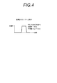
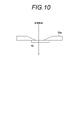
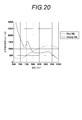
- the graph which shows the relationship between the wavelength in the permeation
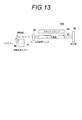
- the block diagram which shows a part of laser light source unit.
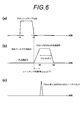
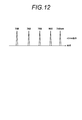
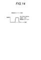
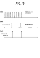
- the timing chart which shows the timing of flash lamp light emission, and the timing of pulsed laser radiation.
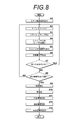
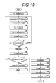
- the timing chart which shows pulsed laser radiation. 6 is a flowchart showing an operation procedure of the photoacoustic image generation apparatus according to the first embodiment.
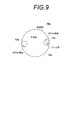
- the mirrors 53 and 54 face each other with the laser rod 51 interposed therebetween, and the mirrors 53 and 54 constitute an optical resonator.
- the mirror 54 is an output side mirror.
- a condensing lens 55 and a wavelength selection unit 56 are disposed in the optical resonator.
- the wavelength selection means 56 controls the wavelength of light resonating in the optical resonator to any one of a plurality of wavelengths to be emitted.
- the condenser lens 55 is disposed between the laser rod 51 and the wavelength selection unit 56, and converges the light incident from the laser rod 51 side and emits the light to the wavelength selection unit 56 side. That is, the condenser lens 55 reduces the beam diameter of the light traveling toward the wavelength selection means 56 in the optical resonator.
- the switching time when the insertion loss in the optical resonator switches from high loss to low loss with the driving of the wavelength selection means 56 is shorter than the generation delay time of the Q switch pulse.
- the transmission region (band pass filter) inserted in the light path is transmitted by switching the region inserted in the light path of the optical resonator from the non-transmission region to the transmission region (first or second band pass filter)
- the optical resonator can perform Q switch pulse oscillation at a wavelength corresponding to the wavelength of the light to be emitted.
- the insertion loss in the optical resonator Changes rapidly from high loss (low Q) to low loss (high Q), and Q switch pulse oscillation occurs (step A4).
- the first transmission region 71 selectively transmits light of wavelength 750 nm, so the laser light source unit 13 emits pulsed laser light of wavelength 750 nm.
- the light emission control unit 61 outputs a Q switch synchronization signal indicating the timing at which the Q switch is turned on, in other words, the timing at which the pulse laser light is emitted (step A5).
- the detection / logarithmic conversion means 28 performs detection / logarithmic conversion processing on the intensity information extracted in step A12.
- the photoacoustic image construction means 29 generates a photoacoustic image based on the phase information extracted in step A11 and the intensity information extracted in step A12 subjected to detection and logarithmic conversion processing ( Step A13). For example, the photoacoustic image constructing unit 29 determines the luminance (tone value) of each pixel in the distribution image of the light absorber based on the intensity information, and determines the color of each pixel based on the phase information. Generate an acoustic image. The generated photoacoustic image is displayed on the image display means 14.
- complex data in which either one of the first photoacoustic data obtained at two wavelengths and the second photoacoustic data is a real part and the other is an imaginary part is generated, and the complex data To generate a reconstructed image by the Fourier transform method.
- reconstruction can be efficiently performed as compared with the case where the first photoacoustic data and the second photoacoustic data are separately reconstructed.
- the pulse laser light of the first wavelength and the pulse laser light of the second wavelength are sequentially applied to the first partial area. Then, a second partial region is sequentially irradiated with pulsed laser light of a first wavelength and pulsed laser light of a second wavelength, and then a third wavelength region is subjected to a first wavelength. And the pulsed laser light of the second wavelength are sequentially irradiated.
- the pulsed laser light of the first wavelength and the pulsed laser light of the second wavelength are continuously irradiated to a certain partial region, and then the light is moved to the next partial region.
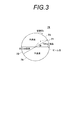
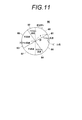
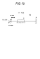
- FIG. 15 shows a part of a laser light source unit 13b using a mirror rotating body having two surfaces as a wavelength selection means.
- One surface of the wavelength selection means (mirror rotator) 56b selectively reflects light of wavelength 750 nm, and the other surface selectively reflects light of wavelength 800 nm.
- FIG. 17 shows a photoacoustic image generation apparatus according to a second embodiment of the present invention.
- the photoacoustic image generation apparatus 10a of this embodiment in addition to the configuration of the ultrasound unit 12 in the photoacoustic image generation apparatus 10 of the first embodiment shown in FIG.
- the photoacoustic image generation apparatus 10 according to the present embodiment is different from the first embodiment in that an ultrasonic image is generated in addition to the photoacoustic image.
- the other parts may be the same as in the first embodiment.
- the probe 11 in addition to the detection of the photoacoustic signal, performs the output (transmission) of the ultrasonic wave to the object and the detection (reception) of the reflected ultrasonic wave from the object to the transmitted ultrasonic wave.
- the trigger control circuit 30 sends an ultrasonic wave transmission trigger signal to the transmission control circuit 37 to instruct ultrasonic wave transmission.
- the transmission control circuit 37 causes the probe 11 to transmit an ultrasonic wave.
- the probe 11 detects the reflected ultrasound from the subject after transmitting the ultrasound.
- the control means 31 determines whether or not there is a remaining wavelength, that is, whether or not all pulse laser beams of a plurality of wavelengths to be emitted have been emitted (step B7). If there is a remaining wavelength, the process returns to step B2 to output pulse laser light of the next wavelength, and the trigger control circuit 30 outputs a flash lamp standby signal to the laser light source unit 13.
- the light emission control unit 61 sends a flash lamp control signal to the flash lamp 52 in step A3 to light the flash lamp 52.
- the photoacoustic image generation apparatus 10 executes steps B1 to B6 for each wavelength of the pulsed laser light to be irradiated to the subject, irradiates the pulsed laser light of each wavelength to the subject, and the photoacoustic from the subject Detect the signal. Steps B1 to B6 may be similar to steps A1 to A6 of FIG.
- the Q switch can be applied even if the beam diameter is large enough not to cause damage on the filter (> 100 ⁇ m).
- the Q-switch repetition is also undesirable for photoacoustics.
- the frequency of flash lamp emission with respect to the rotational frequency of the filter rotator may be lowered, and the Q switch repetition may be controlled to a desired rate to prevent the frequency of the Q switch pulse from rising excessively.
Landscapes
- Physics & Mathematics (AREA)
- Electromagnetism (AREA)
- Engineering & Computer Science (AREA)
- Health & Medical Sciences (AREA)
- Life Sciences & Earth Sciences (AREA)
- Optics & Photonics (AREA)
- Plasma & Fusion (AREA)
- Pathology (AREA)
- General Health & Medical Sciences (AREA)
- Biochemistry (AREA)
- Chemical & Material Sciences (AREA)
- Immunology (AREA)
- General Physics & Mathematics (AREA)
- Analytical Chemistry (AREA)
- Signal Processing (AREA)
- Molecular Biology (AREA)
- Acoustics & Sound (AREA)
- Public Health (AREA)
- Veterinary Medicine (AREA)
- Mathematical Physics (AREA)
- Biomedical Technology (AREA)
- Spectroscopy & Molecular Physics (AREA)
- Surgery (AREA)
- Biophysics (AREA)
- Medical Informatics (AREA)
- Animal Behavior & Ethology (AREA)
- Heart & Thoracic Surgery (AREA)
- Ultra Sonic Daignosis Equipment (AREA)
- Lasers (AREA)
- Investigating Or Analyzing Materials By The Use Of Ultrasonic Waves (AREA)
- Investigating Or Analysing Materials By Optical Means (AREA)
- Mechanical Light Control Or Optical Switches (AREA)
Priority Applications (3)
| Application Number | Priority Date | Filing Date | Title |
|---|---|---|---|
| CN201280047043.4A CN103828145A (zh) | 2011-09-27 | 2012-09-14 | 激光光源单元及光声图像生成装置 |
| EP12835594.8A EP2763248A4 (en) | 2011-09-27 | 2012-09-14 | LASER SOURCE UNIT AND OPTOACUSTIC IMAGE GENERATING DEVICE |
| US14/226,470 US20140202247A1 (en) | 2011-09-27 | 2014-03-26 | Laser source unit and photoacoustic image generation apparatus |
Applications Claiming Priority (4)
| Application Number | Priority Date | Filing Date | Title |
|---|---|---|---|
| JP2011-210143 | 2011-09-27 | ||
| JP2011210143 | 2011-09-27 | ||
| JP2012-198099 | 2012-09-10 | ||
| JP2012198099A JP5730253B2 (ja) | 2011-09-27 | 2012-09-10 | レーザ光源ユニット及び光音響画像生成装置 |
Related Child Applications (1)
| Application Number | Title | Priority Date | Filing Date |
|---|---|---|---|
| US14/226,470 Continuation US20140202247A1 (en) | 2011-09-27 | 2014-03-26 | Laser source unit and photoacoustic image generation apparatus |
Publications (1)
| Publication Number | Publication Date |
|---|---|
| WO2013047250A1 true WO2013047250A1 (ja) | 2013-04-04 |
Family
ID=47995283
Family Applications (1)
| Application Number | Title | Priority Date | Filing Date |
|---|---|---|---|
| PCT/JP2012/073733 Ceased WO2013047250A1 (ja) | 2011-09-27 | 2012-09-14 | レーザ光源ユニット及び光音響画像生成装置 |
Country Status (5)
| Country | Link |
|---|---|
| US (1) | US20140202247A1 (enExample) |
| EP (1) | EP2763248A4 (enExample) |
| JP (1) | JP5730253B2 (enExample) |
| CN (1) | CN103828145A (enExample) |
| WO (1) | WO2013047250A1 (enExample) |
Families Citing this family (15)
| Publication number | Priority date | Publication date | Assignee | Title |
|---|---|---|---|---|
| JP6207257B2 (ja) * | 2013-06-26 | 2017-10-04 | キヤノン株式会社 | 被検体情報取得およびレーザ装置 |
| JP6257190B2 (ja) * | 2013-07-09 | 2018-01-10 | キヤノン株式会社 | 被検体情報取得装置およびレーザー装置 |
| JP6411120B2 (ja) * | 2014-08-04 | 2018-10-24 | 株式会社アマダミヤチ | レーザ装置 |
| JP6452110B2 (ja) * | 2015-02-06 | 2019-01-16 | キヤノン株式会社 | 手持ち式プローブ |
| US10281369B2 (en) * | 2015-12-23 | 2019-05-07 | VOR, Inc. | Dual-image based bioimaging devices and techniques |
| EP3251578A1 (en) * | 2016-05-30 | 2017-12-06 | Leica Instruments (Singapore) Pte. Ltd. | Medical device for the observation of a partly fluorescent object, using a filter system with a transmission window |
| JP2018050776A (ja) * | 2016-09-27 | 2018-04-05 | キヤノン株式会社 | 光音響装置、情報処理方法、及びプログラム |
| JP2018050775A (ja) | 2016-09-27 | 2018-04-05 | キヤノン株式会社 | 光音響装置、情報処理方法、及びプログラム |
| JP6759032B2 (ja) | 2016-09-27 | 2020-09-23 | キヤノン株式会社 | 光音響装置、情報処理方法、及びプログラム |
| JP2018094279A (ja) * | 2016-12-16 | 2018-06-21 | 株式会社日立製作所 | 光音響型のカテーテル及び光音響型のカテーテルシステム |
| JP6448008B2 (ja) * | 2017-10-05 | 2019-01-09 | キヤノン株式会社 | 被検体情報取得装置およびレーザ装置 |
| CN108992042B (zh) * | 2018-08-16 | 2023-10-20 | 杭州麦依科技有限公司 | 一种便携式静脉显像仪及其控制方法 |
| JP6842126B2 (ja) * | 2019-05-10 | 2021-03-17 | 国立大学法人広島大学 | 振動解析システム、振動解析方法及びプログラム |
| CN110477852B (zh) * | 2019-08-02 | 2024-06-18 | 佛山科学技术学院 | 一种虹膜血管成像系统 |
| CA3235643A1 (en) * | 2021-10-21 | 2023-04-27 | Evident Canada, Inc. | Color representation of complex-valued ndt data |
Citations (8)
| Publication number | Priority date | Publication date | Assignee | Title |
|---|---|---|---|---|
| JPH1065238A (ja) | 1996-08-23 | 1998-03-06 | Mitsubishi Cable Ind Ltd | 固体レーザ装置 |
| JPH1065260A (ja) | 1996-08-23 | 1998-03-06 | Mitsubishi Cable Ind Ltd | 固体レーザ装置 |
| JP2000105464A (ja) * | 1998-09-29 | 2000-04-11 | Toshiba Corp | レーザ照射装置及び露光装置 |
| JP2001044548A (ja) * | 1999-01-14 | 2001-02-16 | Nippon Telegr & Teleph Corp <Ntt> | 光発生方法及び光源 |
| JP2005021380A (ja) | 2003-07-02 | 2005-01-27 | Toshiba Corp | 生体情報映像装置 |
| JP2007235063A (ja) | 2006-03-03 | 2007-09-13 | Tokyo Institute Of Technology | Qスイッチレーザおよびqスイッチ発振方法 |
| JP2010046215A (ja) | 2008-08-20 | 2010-03-04 | Canon Inc | 生体情報イメージング装置および生体情報イメージング方法 |
| JP2011083531A (ja) * | 2009-10-19 | 2011-04-28 | Canon Inc | 音響波測定装置、音響波画像化装置および音響波測定装置の制御方法 |
Family Cites Families (7)
| Publication number | Priority date | Publication date | Assignee | Title |
|---|---|---|---|---|
| US4809283A (en) * | 1988-02-26 | 1989-02-28 | Allied-Signal Inc. | Method of manufacturing chromium-doped beryllium aluminate laser rod and lasers incorporating the rods therein |
| JPH0311778A (ja) * | 1989-06-09 | 1991-01-21 | Matsushita Electric Ind Co Ltd | 半導体レーザ励起固体レーザ装置 |
| JPH09152640A (ja) * | 1995-11-30 | 1997-06-10 | Nidek Co Ltd | レ−ザ装置 |
| US5977538A (en) * | 1998-05-11 | 1999-11-02 | Imarx Pharmaceutical Corp. | Optoacoustic imaging system |
| EP1311189A4 (en) * | 2000-08-21 | 2005-03-09 | Euro Celtique Sa | Near-BLOOD GLUCOSE MONITORING DEVICE |
| JP4343594B2 (ja) * | 2003-06-23 | 2009-10-14 | オリンパス株式会社 | 内視鏡装置 |
| EP2034878A2 (en) * | 2006-06-23 | 2009-03-18 | Koninklijke Philips Electronics N.V. | Timing controller for combined photoacoustic and ultrasound imager |
-
2012
- 2012-09-10 JP JP2012198099A patent/JP5730253B2/ja active Active
- 2012-09-14 WO PCT/JP2012/073733 patent/WO2013047250A1/ja not_active Ceased
- 2012-09-14 CN CN201280047043.4A patent/CN103828145A/zh active Pending
- 2012-09-14 EP EP12835594.8A patent/EP2763248A4/en not_active Withdrawn
-
2014
- 2014-03-26 US US14/226,470 patent/US20140202247A1/en not_active Abandoned
Patent Citations (8)
| Publication number | Priority date | Publication date | Assignee | Title |
|---|---|---|---|---|
| JPH1065238A (ja) | 1996-08-23 | 1998-03-06 | Mitsubishi Cable Ind Ltd | 固体レーザ装置 |
| JPH1065260A (ja) | 1996-08-23 | 1998-03-06 | Mitsubishi Cable Ind Ltd | 固体レーザ装置 |
| JP2000105464A (ja) * | 1998-09-29 | 2000-04-11 | Toshiba Corp | レーザ照射装置及び露光装置 |
| JP2001044548A (ja) * | 1999-01-14 | 2001-02-16 | Nippon Telegr & Teleph Corp <Ntt> | 光発生方法及び光源 |
| JP2005021380A (ja) | 2003-07-02 | 2005-01-27 | Toshiba Corp | 生体情報映像装置 |
| JP2007235063A (ja) | 2006-03-03 | 2007-09-13 | Tokyo Institute Of Technology | Qスイッチレーザおよびqスイッチ発振方法 |
| JP2010046215A (ja) | 2008-08-20 | 2010-03-04 | Canon Inc | 生体情報イメージング装置および生体情報イメージング方法 |
| JP2011083531A (ja) * | 2009-10-19 | 2011-04-28 | Canon Inc | 音響波測定装置、音響波画像化装置および音響波測定装置の制御方法 |
Non-Patent Citations (3)
| Title |
|---|
| JONATHAN I. SPERL ET AL.: "Photoacoustic Image Reconstruction-A Quantitative Analysis", SPIE-OSA, vol. 6631, pages 663103 |
| See also references of EP2763248A4 |
| XUEDING WANG; JONATHAN CANNATA; DEREK DE BUSSCHERE; CHANGHONG HU; J. BRIAN FOWLKES; PAUL CARSON: "A High-Speed Photoacoustic Tomography System based on a Commercial Ultrasound and a Custom Transducer Array", PROC. SPIE, vol. 7564, 23 February 2010 (2010-02-23), pages 756424 |
Also Published As
| Publication number | Publication date |
|---|---|
| CN103828145A (zh) | 2014-05-28 |
| EP2763248A4 (en) | 2015-09-02 |
| JP5730253B2 (ja) | 2015-06-03 |
| EP2763248A1 (en) | 2014-08-06 |
| US20140202247A1 (en) | 2014-07-24 |
| JP2013084923A (ja) | 2013-05-09 |
Similar Documents
| Publication | Publication Date | Title |
|---|---|---|
| JP5730253B2 (ja) | レーザ光源ユニット及び光音響画像生成装置 | |
| JP5662973B2 (ja) | レーザ光源ユニット、その制御方法、光音響画像生成装置及び方法 | |
| JP5713968B2 (ja) | 光音響画像生成装置及び音響波ユニット | |
| EP2744053B1 (en) | Laser light source unit, control method for same, and device and method for generating photoacoustic image | |
| JP5681675B2 (ja) | 光音響画像生成装置及び音響波ユニット | |
| WO2012120889A1 (ja) | 断層画像生成装置及び方法 | |
| WO2012114729A1 (ja) | 光音響画像生成装置、及び方法 | |
| WO2012120885A1 (ja) | 光音響計測装置 | |
| JP5694991B2 (ja) | 光音響画像化方法および装置 | |
| JP2013214703A (ja) | レーザ装置及び光音響計測装置 | |
| JP2015029048A (ja) | レーザ装置及び光音響計測装置 | |
| JP2013106822A (ja) | 光音響画像生成装置および光音響画像生成方法 | |
| JP2013214722A (ja) | レーザ装置及び光音響計測装置 | |
| WO2013129105A1 (ja) | レーザ光源ユニット、その制御方法および光音響画像生成装置 | |
| JP2014064733A (ja) | 光音響計測装置 |
Legal Events
| Date | Code | Title | Description |
|---|---|---|---|
| 121 | Ep: the epo has been informed by wipo that ep was designated in this application |
Ref document number: 12835594 Country of ref document: EP Kind code of ref document: A1 |
|
| NENP | Non-entry into the national phase |
Ref country code: DE |
|
| WWE | Wipo information: entry into national phase |
Ref document number: 2012835594 Country of ref document: EP |