WO2013046897A1 - 立体画像表示システム - Google Patents
立体画像表示システム Download PDFInfo
- Publication number
- WO2013046897A1 WO2013046897A1 PCT/JP2012/069087 JP2012069087W WO2013046897A1 WO 2013046897 A1 WO2013046897 A1 WO 2013046897A1 JP 2012069087 W JP2012069087 W JP 2012069087W WO 2013046897 A1 WO2013046897 A1 WO 2013046897A1
- Authority
- WO
- WIPO (PCT)
- Prior art keywords
- group
- film
- acid
- carbon atoms
- retardation
- Prior art date
- Legal status (The legal status is an assumption and is not a legal conclusion. Google has not performed a legal analysis and makes no representation as to the accuracy of the status listed.)
- Ceased
Links
Images


Classifications
-
- G—PHYSICS
- G03—PHOTOGRAPHY; CINEMATOGRAPHY; ANALOGOUS TECHNIQUES USING WAVES OTHER THAN OPTICAL WAVES; ELECTROGRAPHY; HOLOGRAPHY
- G03B—APPARATUS OR ARRANGEMENTS FOR TAKING PHOTOGRAPHS OR FOR PROJECTING OR VIEWING THEM; APPARATUS OR ARRANGEMENTS EMPLOYING ANALOGOUS TECHNIQUES USING WAVES OTHER THAN OPTICAL WAVES; ACCESSORIES THEREFOR
- G03B35/00—Stereoscopic photography
- G03B35/18—Stereoscopic photography by simultaneous viewing
- G03B35/26—Stereoscopic photography by simultaneous viewing using polarised or coloured light separating different viewpoint images
-
- G—PHYSICS
- G02—OPTICS
- G02B—OPTICAL ELEMENTS, SYSTEMS OR APPARATUS
- G02B30/00—Optical systems or apparatus for producing three-dimensional [3D] effects, e.g. stereoscopic images
- G02B30/20—Optical systems or apparatus for producing three-dimensional [3D] effects, e.g. stereoscopic images by providing first and second parallax images to an observer's left and right eyes
- G02B30/22—Optical systems or apparatus for producing three-dimensional [3D] effects, e.g. stereoscopic images by providing first and second parallax images to an observer's left and right eyes of the stereoscopic type
- G02B30/25—Optical systems or apparatus for producing three-dimensional [3D] effects, e.g. stereoscopic images by providing first and second parallax images to an observer's left and right eyes of the stereoscopic type using polarisation techniques
Definitions
- the present invention relates to a stereoscopic image display system. More specifically, the present invention relates to a stereoscopic image display system with improved hue (color tone) change and crosstalk in an oblique direction, and more particularly, to a stereoscopic image display system provided with an organic electroluminescence element.
- a stretched film obtained by stretching a resin film is used as an optical material such as a component of a display device by utilizing its optical anisotropy.
- the stretched film is used as a retardation film for optical compensation such as anti-coloring and viewing angle expansion, or the stretched film and a polarizer are bonded together to be used as a polarizing plate. It has been known.
- organic electroluminescence display devices hereinafter also referred to as “organic EL display devices”
- stereoscopic image display devices In recent years, the retardation film has been required for improving the display quality of organic electroluminescence display devices (hereinafter also referred to as “organic EL display devices”) and stereoscopic image display devices.
- a self-luminous display device in which a light source corresponding to each color is turned on, such as an organic EL display device, it is not necessary to install a color filter that causes a reduction in contrast, so that the contrast can be further increased.
- a reflector such as an aluminum plate is provided on the back side of the display in order to increase the light extraction efficiency. Therefore, external light incident on the display is reflected by the reflector and the image is displayed. There is a problem of lowering the contrast. For this reason, it is known that the stretched film and a polarizer are bonded to form a circularly polarizing plate and used on the surface side of the display in order to improve contrast of light and darkness by preventing external light reflection (see Patent Document 1).
- the circularly polarizing plate needs to have the in-plane slow axis of the stretched film bonded at a desired angle with respect to the transmission axis of the polarizer, and has a phase difference value of 1 ⁇ 4 of the wavelength of the viewing light.
- a retardation film also referred to as a ⁇ / 4 retardation film or a ⁇ / 4 plate in this application
- An example is the combination.
- stereoscopic image display devices On the other hand, several methods are known for stereoscopic image display devices. One of them is a stereoscopic image viewing glasses with a liquid crystal shutter function. There is a method of allowing an observer to recognize a (three-dimensional: 3D) image. What is currently viewed as promising in this method is that the right-eye image and the left-eye image, which are parallax images, are alternately displayed in time series on the display that displays the image, and the observer uses glasses for viewing stereoscopic images. A method of wearing an image and viewing an image of a liquid crystal display device (see, for example, Patent Document 5).
- a stereoscopic image display device when viewing a stereoscopic (three-dimensional: 3D) image of a liquid crystal display device by wearing polarized glasses, the polarization angle of the polarized glasses and the angle of polarization emitted from the liquid crystal display device are determined from appropriate angles. There was a problem that the image was doubled when shifted. In order to prevent this, there is a need for a retardation film having a retardation value (also referred to as “retardation value”) that is 1 ⁇ 4 of the wavelength of the viewing light.
- retardation value also referred to as “retardation value”
- an organic EL stereoscopic image display device (hereinafter also referred to as “3D-OLED”) in which an organic EL light emitting element and a stereoscopic image display device are combined has become a new need in the market.
- the 3D-OLED has a problem that the hue (hue) change when viewed from an oblique direction is more remarkable than that of a normal (two-dimensional) organic EL display device.
- a polarizing plate protected with a retardation film having both in-plane retardation of ⁇ / 4 is pasted on a display device, and a ⁇ / 4 retardation film is also pasted on shutter glasses. It can be predicted from the prior art that a circularly polarizing plate is used.
- the present invention has been made in view of the above-described problems and situations, and a solution to that problem is a stereoscopic image display system with improved hue (color) change and crosstalk in an oblique direction, particularly an organic electroluminescence element.
- a stereoscopic image display system is provided.
- the present inventor has solved the above-mentioned problem by using a polarizing plate including a retardation film having specific optical characteristics in a stereoscopic image display device.
- the inventors have found that the problem can be solved, and have reached the present invention.
- a stereoscopic image display system comprising an image display device having at least a polarizing plate and a light emitting element and glasses having at least a polarizer, wherein the polarizing plate satisfies the following requirements (a) to (c): Stereoscopic image display system characterized by (A) On the both sides of the polarizer drawn out from the long roll, the retardation film having the following optical characteristics is drawn out from the long roll in the same direction as the long direction of the polarizer. It is formed by bonding.
- the slow axis of the retardation film bonded to both surfaces of the polarizer is in the direction between the two different from the longitudinal direction and the width direction of the polarizer, and is on both surfaces of the polarizer.
- the slow axes of the retardation film are bonded in directions orthogonal to each other.
- C The in-plane retardation value Ro of the retardation film and the retardation value Rt in the thickness direction measured at an optical wavelength of 550 nm under an environment of a temperature of 23 ° C. and a relative humidity of 55% are respectively represented by the following formulas ( 1) to (4) are satisfied.
- Rt (T1) represents the retardation value Rt in the thickness direction of the retardation film T1 bonded to the viewing side of the polarizer of the polarizing plate laminated on the light emitting element.
- Rt (T2) Represents the retardation value Rt in the thickness direction of the retardation film T2 bonded to the light emitting element side of the polarizer of the polarizing plate laminated on the light emitting element.
- an image display device with improved hue (color) change and crosstalk in an oblique direction, particularly a stereoscopic image display system provided with an organic electroluminescence element.
- the stereoscopic image display system of the present invention is a stereoscopic image display system including an image display device having at least a polarizing plate and a light-emitting element, and glasses having at least a polarizer. A) to (c) are satisfied.
- the light emitting element is an organic electroluminescence element from the viewpoint of the effect of the present invention.
- the retardation film contains a cellulose ester having a total acyl group substitution degree in the range of 2.0 to 2.6 because predetermined optical characteristics can be obtained.
- ⁇ is used to mean that the numerical values described before and after it are included as a lower limit value and an upper limit value.
- the stereoscopic image display system of the present invention is a stereoscopic image display system including an image display device having at least a polarizing plate and a light emitting element, and glasses having at least a polarizer, and the polarizing plate has the following requirements ( A) to (c) are satisfied.
- the retardation film having the following optical characteristics is drawn out from the long roll in the same direction as the long direction of the polarizer. It is formed by bonding.
- the slow axis of the retardation film bonded to both surfaces of the polarizer is in the direction between the two different from the longitudinal direction and the width direction of the polarizer, and is on both surfaces of the polarizer.
- the slow axes of the retardation film are bonded in directions orthogonal to each other.
- C The in-plane retardation value Ro of the retardation film and the retardation value Rt in the thickness direction measured at an optical wavelength of 550 nm under an environment of a temperature of 23 ° C. and a relative humidity of 55% are respectively represented by the following formulas ( 1) to (4) are satisfied.
- Rt (T2) Represents the retardation value Rt in the thickness direction of the retardation film T2 bonded to the light emitting element side of the polarizer of the polarizing plate laminated on the light emitting element.
- the said light emitting element is an organic electroluminescent element.
- the retardation film contains a cellulose ester having a total acyl group substitution degree in the range of 2.0 to 2.6 since the predetermined optical characteristics can be obtained.
- the polarizing plate according to the present invention has the following three roles.
- the above (a) and (b) are roles as a solution to a known problem.
- a ⁇ / 4 retardation film is bonded to one surface of the polarizer, and the other surface does not have a retardation value (particularly an in-plane retardation value).
- a polarizer protective film is bonded. At this time, the polarizer is bonded at an angle between the absorption axis of the polarizer and the slow axis of the ⁇ / 4 retardation film in the range of 25 to 65 °, preferably 45 °.
- the difference between (a) and (b) is whether the ⁇ / 4 retardation film is arranged on the viewing side or the display panel side with respect to the polarizer.
- the above-mentioned role can be achieved by arranging a ⁇ / 4 retardation film on the viewing side (T1) in (a) and on the panel side (T2) in (b).
- a circularly polarizing plate is required for shutter glasses for stereoscopic (3D) video.
- a ⁇ / 4 retardation film is bonded to both sides of the polarizer.
- the laminating direction is such that the angle formed by the absorption axis of the polarizer and the slow axis of the ⁇ / 4 retardation film is 45 °, and ⁇ / The slow axes of the four retardation films are orthogonal to each other.
- the means is (i) and (ii) above.
- the range of the retardation value Rt in the thickness direction required for the ⁇ / 4 retardation film disposed at T1 and T2 is slightly different as represented by the equations (2) and (3).
- the range of Rt required for the ⁇ / 4 retardation film of T1 is in the range of 20 to 250 nm, preferably in the range of 50 to 150 nm, and more preferably in the range of 60 to 100 nm.
- the range of Rt required for the ⁇ / 4 retardation film of T2 is in the range of 0 to 100 nm, preferably in the range of 10 to 80 nm, and more preferably in the range of 20 to 50 nm.
- a ⁇ / 4 retardation film outside this range is arranged at T2
- the color variation due to the viewing angle increases.
- Rt ratio value Rt (T2) / Rt (T1) of ⁇ / 4 retardation film of T1 and T2 is in the range of 0 to 1.7, preferably in the range of 0.1 to 1.2. More preferably, it is in the range of 0.4 to 1.0.
- the ⁇ / 4 retardation film (also referred to as “ ⁇ / 4 plate”) according to the present invention has a function of converting linearly polarized light having a specific wavelength into circularly polarized light (or converting circularly polarized light into linearly polarized light).
- the ⁇ / 4 retardation film has an in-plane retardation value Ro of about 1 ⁇ 4 for a predetermined wavelength of light (usually in the visible light region).
- Ro (550) measured at a wavelength of 550 nm is preferably in the range of 108 to 168 nm, Ro (550) is preferably 120 to 160 nm, and Ro (550) is 130. More preferably, it is ⁇ 150 nm.
- the ⁇ / 4 retardation film according to the present invention has a phase difference (retardation) of approximately 1 ⁇ 4 of the wavelength in the visible light wavelength range in order to obtain almost perfect circularly polarized light in the visible light wavelength range.
- a retardation film is preferred.
- a phase difference (retardation) of approximately 1 ⁇ 4 in the wavelength range of visible light is expressed by the following formula (I) measured at a wavelength of 450 nm.
- the difference Ro (550) ⁇ Ro (450) between the phase difference value Ro (450) and the phase difference value Ro (550) measured at a wavelength of 550 nm is preferably in the range of 2 to 34 nm. Is more preferable, and a range of 8 to 28 nm is particularly preferable.
- Formula (I): Ro (n x ⁇ n y ) ⁇ d
- Rt ⁇ (n x + n y ) / 2 ⁇ n z ⁇ ⁇ d
- n x, n y, n z is, 23 °C ⁇ 55% RH, say 450 nm
- Ny reffractive index in the direction perpendicular to the slow axis in the film plane
- nz reffractive index of the film in the thickness direction
- d is the thickness (nm) of the film.
- Retardation values Ro and Rt can be measured using an automatic birefringence meter.
- Ro and Rt are calculated by birefringence measurement at each wavelength in an environment of 23 ° C. and 55% RH.
- a circularly polarizing plate is obtained by laminating so that the angle between the slow axis of the ⁇ / 4 retardation film and the transmission axis of the polarizer described later is substantially 45 °.
- “Substantially 45 °” means a range of 40 to 50 °.
- the angle between the in-plane slow axis of the ⁇ / 4 retardation film and the transmission axis of the polarizer is preferably in the range of 41 to 49 °, more preferably in the range of 42 to 48 °, 43 A range of ⁇ 47 ° is more preferred, and a range of 44-46 ° is most preferred.
- the cellulose ester according to the present invention preferably has a total acyl group substitution degree in the range of 2.0 to 2.6, more preferably in the range of 2.2 to 2.5.
- the total acyl group substitution degree is the average value of the number of esterified (acylated) hydroxy groups (hydroxyl groups) among the three hydroxy groups (hydroxyl groups) of each anhydroglucose constituting the cellulose. Indicates a value in the range of 0-3.
- the part which is not substituted usually exists as a hydroxy group (hydroxyl group).
- substitution degree of the acyl group was determined by the method prescribed in ASTM-D817-96 (test method for cellulose acetate and the like).
- the number average molecular weight (Mn) of the cellulose ester according to the present invention is preferably in the range of 30,000 to 300,000, since the mechanical strength of the resulting film is strong. Further, 50,000 to 200,000 are preferably used.
- the ratio Mw / Mn of the weight average molecular weight (Mw) and the number average molecular weight (Mn) of the cellulose ester is preferably 1.4 to 3.0.
- the weight average molecular weight Mw and number average molecular weight Mn of the cellulose ester were measured using gel permeation chromatography (GPC).
- the measurement conditions are as follows.
- the cellulose as a raw material of the cellulose ester according to the present invention is not particularly limited, and examples thereof include cotton linter, wood pulp, and kenaf. Moreover, the cellulose ester obtained from them can be mixed and used in arbitrary ratios, respectively.
- the cellulose ester according to the present invention can be produced by a known method.
- cellulose is mixed with raw material cellulose, a predetermined organic acid (such as acetic acid), acid anhydride (such as acetic anhydride), and a catalyst (such as sulfuric acid) to esterify (acetylate) cellulose,
- a predetermined organic acid such as acetic acid
- acid anhydride such as acetic anhydride
- a catalyst such as sulfuric acid
- the ⁇ / 4 retardation film according to the present invention may contain calcium and magnesium.
- the total amount of calcium and magnesium and the amount of acetic acid preferably satisfy the following relational expression (a).
- the acid catalyst especially sulfuric acid
- It may be added as a hydroxide or metal salt (inorganic acid salt, organic acid salt).
- you may add as a metal oxide, a metal hydroxide, and a metal salt (inorganic acid salt, organic acid salt) at the time of optical film forming.
- acetic anhydride or acetic acid is used as a reaction solvent or an esterifying agent. Unreacted acetic anhydride is hydrolyzed by a reaction stopper (water, alcohol, acetic acid, etc.) to produce acetic acid.
- a reaction stopper water, alcohol, acetic acid, etc.
- the amount of acetic acid contained in the ⁇ / 4 retardation film refers to the total amount of residual acetic acid and free acetic acid.
- the total amount of calcium and magnesium contained in the ⁇ / 4 retardation film is preferably in the range of 5 to 130 ppm, more preferably in the range of 5 to 80 ppm, and still more preferably in the range of 5 to 50 ppm.
- the calcium and magnesium contained in the ⁇ / 4 retardation film can be quantified by a known method. For example, after the dried cellulose ester is completely burned, the ash is dissolved in hydrochloric acid and pretreated. It can be measured by the atomic absorption method after the measurement. The measured value is obtained in units of ppm as the calcium and magnesium contents in 1 g of the completely dry cellulose ester.
- the amount of acetic acid contained in the ⁇ / 4 retardation film is preferably in the range of 20 to 500 ppm, more preferably in the range of 25 to 250 ppm, and still more preferably in the range of 30 to 150 ppm.
- a known method can be used for quantification of acetic acid contained in the ⁇ / 4 retardation film.
- the following method can be used.
- the ⁇ / 4 retardation film is dissolved in methylene chloride, and methanol is added to perform reprecipitation.
- the amount of acetic acid can be obtained by filtering the supernatant and measuring the supernatant with gas chromatography.
- the melting point of the ⁇ / 4 retardation film according to the present invention is preferably in the range of 200 to 290 ° C.
- Methods for adjusting the melting point within the above range include controlling the degree of substitution of the cellulose ester or adding a plasticizer.
- the ⁇ / 4 retardation film according to the present invention can be used in combination with a thermoplastic resin other than the cellulose ester as long as the effects of the present invention are not impaired.
- thermoplastic resin refers to a resin that becomes soft when heated to the glass transition temperature or melting point and can be molded into the desired shape.
- thermoplastic resins polyethylene (PE), high density polyethylene, medium density polyethylene, low density polyethylene, polypropylene (PP), polyvinyl chloride (PVC), polyvinylidene chloride, polystyrene (PS), polyvinyl acetate (PVAc) Teflon (registered trademark) (polytetrafluoroethylene, PTFE), ABS resin (acrylonitrile butadiene styrene resin), AS resin, acrylic resin (PMMA), and the like can be used.
- PE polyethylene
- PVC polyvinyl chloride
- PS polyvinylidene chloride
- PS polystyrene
- PVAc polyvinyl acetate
- Teflon polytetrafluoroethylene
- AS resin acrylic resin
- PMMA acrylic resin
- PA polyamide
- nylon polyacetal
- PC polycarbonate
- m-PPE modified polyphenylene ether
- PBT polybutylene terephthalate
- PET Polyethylene terephthalate
- GF-PET glass fiber reinforced polyethylene terephthalate
- COP cyclic polyolefin
- polyphenylene sulfide PPS
- polytetrafluoroethylene PTFE
- polysulfone polyethersulfone
- amorphous polyarylate liquid crystal polymer
- polyether Ether ketone thermoplastic polyimide (PI)
- PAI polyamideimide
- the residual sulfuric acid content in the cellulose ester according to the present invention is preferably in the range of 0.1 to 40 ppm in terms of elemental sulfur. These are considered to be contained in the form of salts. If the residual sulfuric acid content exceeds 40 ppm, the deposit on the die lip during heat melting increases, such being undesirable. Moreover, since it becomes easy to fracture
- a smaller amount is preferable, but if it is less than 0.1, it is not preferable because the load of the cellulose ester washing process becomes too large, and it is not preferable because it may easily break. This is not well understood, although an increase in the number of washings may affect the resin. Further, the range of 0.1 to 30 ppm is preferable.
- the residual sulfuric acid content can be similarly measured by ASTM-D817-96.
- the total residual acid amount including other (such as acetic acid) residual acid is preferably 1000 ppm or less, more preferably 500 ppm or less, and even more preferably 100 ppm or less.
- a poor solvent such as methanol or ethanol, or, as a result, a mixed solvent of a poor solvent and a good solvent can be used if it is a poor solvent. Organic impurities can be removed.
- cellulose ester In order to improve the heat resistance, mechanical properties, optical properties, etc. of cellulose ester, it can be dissolved in a good solvent of cellulose ester and then reprecipitated in a poor solvent to remove low molecular weight components and other impurities of cellulose ester. it can. Furthermore, another polymer or a low molecular weight compound may be added after the reprecipitation treatment of the cellulose ester.
- the cellulose ester used in the present invention preferably has few bright spot foreign matters when formed into a film.
- a bright spot foreign material is an arrangement in which two polarizing plates are arranged orthogonally (crossed Nicols), a cellulose ester film is placed between them, light from the light source is applied from one side, and the cellulose ester film is applied from the other side. This is the point where the light from the light source appears to leak when observed.
- the polarizing plate used for the evaluation is desirably composed of a protective film having no bright spot foreign matter, and a polarizing plate using a glass plate for protecting the polarizer is preferably used.
- the cause of bright spot foreign matter is considered to be one of the causes of unacetylated or low acetylated cellulose contained in cellulose ester.
- Use of cellulose ester with little bright spot foreign substance and filtration of molten cellulose ester or cellulose ester solution It is also possible to remove the bright spot foreign matter through the filtration step in the same manner once in the solution state in at least one of the process of synthesizing the cellulose ester and the process of obtaining the precipitate. Since the molten resin has a high viscosity, the latter method is more efficient.
- 0.01 mm or more is preferably 200 pieces / cm 2 or less, more preferably 100 pieces / cm 2 or less, further preferably 50 pieces / cm 2 or less, and 30 pieces / cm 2 or less.
- the number is preferably 10 pieces / cm 2 or less, but most preferably none.
- the bright spots of 0.005 to 0.01 mm or less are preferably 200 pieces / cm 2 or less, more preferably 100 pieces / cm 2 or less, and 50 pieces / cm 2 or less.
- the number is preferably 30 pieces / cm 2 or less, more preferably 10 pieces / cm 2 or less, and most preferably none.
- the cellulose ester composition (also referred to as a dope) to which a plasticizer, an ultraviolet absorber, an antioxidant, a stabilizer and the like are added and mixed is filtered rather than filtering the cellulose ester alone.
- the cellulose ester may be dissolved in a solvent during the synthesis and reduced by filtration. Filtration is preferably performed with the viscosity of the melt containing the cellulose ester being 10,000 P or less, more preferably 5000 P or less, still more preferably 1000 P or less, and even more preferably 500 P or less.
- the filter medium conventionally known materials such as glass fibers, cellulose fibers, filter paper, and fluorine resins such as tetrafluoroethylene resin are preferably used, and ceramics and metals are particularly preferably used.
- the absolute filtration accuracy is preferably 50 ⁇ m or less, more preferably 30 ⁇ m or less, still more preferably 10 ⁇ m or less, and even more preferably 5 ⁇ m or less. These can be used in combination as appropriate.
- the filter medium can be either a surface type or a depth type, but the depth type is preferably used because it is relatively less clogged.
- the ⁇ / 4 retardation film according to the present invention may be obtained by appropriately mixing polymer components other than the cellulose ester resin.
- the polymer component to be mixed is preferably one having excellent compatibility with the cellulose ester, and the transmittance when formed into a film is preferably 80% or more, more preferably 90% or more, and further preferably 92% or more.
- Organic solvents that dissolve cellulose esters and are useful for forming cellulose ester solutions or dopes include chlorinated organic solvents and non-chlorinated organic solvents.
- Methylene chloride methylene chloride
- non-chlorine organic solvent examples include methyl acetate, ethyl acetate, amyl acetate, acetone, tetrahydrofuran, 1,3-dioxolane, 1,4-dioxane, cyclohexanone, ethyl formate, 2,2,2-trifluoroethanol, 2,2,3,3-hexafluoro-1-propanol, 1,3-difluoro-2-propanol, 1,1,1,3,3,3-hexafluoro-2-methyl-2-propanol, 1, Examples include 1,1,3,3,3-hexafluoro-2-propanol, 2,2,3,3,3-pentafluoro-1-propanol, and nitroethane.
- a dissolution method at room temperature can be used, but an insoluble material can be obtained by using a dissolution method such as a high-temperature dissolution method, a cooling dissolution method, or a high-pressure dissolution method. Can be reduced, which is preferable.
- Methylene chloride can be used for cellulose esters other than cellulose triacetate, but methyl acetate, ethyl acetate, and acetone are preferably used. Particularly preferred is methyl acetate.
- an organic solvent having good solubility with respect to the cellulose ester is referred to as a good solvent, and has a main effect on dissolution, and an organic solvent used in a large amount among them is a main (organic) solvent or a main ( Organic) solvent.
- the dope used in the present invention preferably contains an alcohol having 1 to 4 carbon atoms in the range of 1 to 40% by mass.
- these are gelling solvents that make dope film (web) gel when the dope is cast on a metal support and the solvent starts to evaporate and the ratio of alcohol increases, making the web strong and easy to peel off from the metal support. When these ratios are small, there is also a role of promoting the dissolution of the cellulose ester of the non-chlorine organic solvent.
- the alcohol having 1 to 4 carbon atoms include methanol, ethanol, n-propanol, iso-propanol, n-butanol, sec-butanol, and tert-butanol. Of these, ethanol is preferred because it has excellent dope stability, has a relatively low boiling point, and has good drying properties.
- These organic solvents are called poor solvents because they are not soluble in cellulose esters alone.
- the concentration of the cellulose ester in the dope is adjusted in the range of 15 to 30% by mass and the dope viscosity in the range of 100 to 500 Pa ⁇ s.
- Additives added to the dope include plasticizers, ultraviolet absorbers, retardation adjusting agents, antioxidants, deterioration inhibitors, peeling aids, surfactants, dyes, fine particles, and the like.
- additives other than fine particles may be added during the preparation of the cellulose ester solution, or may be added during the preparation of the fine particle dispersion. It is preferable to add a plasticizer, an antioxidant, an ultraviolet absorber, or the like that imparts heat and moisture resistance to the polarizing plate used in the liquid crystal image display device. The additive will be described below.
- R 1 to R 8 each independently represents a hydrogen atom, a substituted or unsubstituted alkylcarbonyl group, or a substituted or unsubstituted arylcarbonyl group, and R 1 to R 8 are mutually May be the same or different.
- the total average degree of substitution of the compound represented by the general formula (1) added to the cellulose ester film in the present invention is in the range of 6.1 to 6.9, and the range of the degree of substitution is 4.0 to 6.9. A range of 8.0 is preferable.
- the substitution degree distribution may be adjusted to the desired substitution degree by adjusting the esterification reaction time or mixing compounds having different substitution degrees.
- Plasticizer A compound known as a plasticizer is added to the ⁇ / 4 retardation film according to the present invention for the purpose of improving mechanical properties, imparting flexibility, imparting water absorption resistance, reducing water vapor transmission rate, adjusting retardation, etc.
- phosphoric acid esters and carboxylic acid esters are preferably used.
- the plasticizer is preferably contained in the ⁇ / 4 retardation film in the range of 1 to 40% by mass, particularly in the range of 1 to 30% by mass.
- phosphate ester examples include triphenyl phosphate, tricresyl phosphate, phenyl diphenyl phosphate, and the like.
- carboxylic acid esters examples include phthalic acid esters and citric acid esters; phthalic acid esters such as dimethyl phthalate, diethyl phosphate, dioctyl phthalate and diethyl hexyl phthalate; and citrate esters such as acetyl triethyl citrate and acetyl citrate. Mention may be made of tributyl. Other examples include butyl oleate, methylacetyl ricinoleate, dibutyl sebacate, and triacetin. Alkylphthalylalkyl glycolates are also preferably used for this purpose.
- the alkyl in the alkylphthalylalkyl glycolate is an alkyl group having 1 to 8 carbon atoms.
- alkyl phthalyl alkyl glycolates include methyl phthalyl methyl glycolate, ethyl phthalyl ethyl glycolate, propyl phthalyl propyl glycolate, butyl phthalyl butyl glycolate, octyl phthalyl octyl glycolate, methyl phthalyl ethyl glycolate, Ethyl phthalyl methyl glycolate, ethyl phthalyl propyl glycolate, propyl phthalyl ethyl glycolate, methyl phthalyl propyl glycolate, methyl phthalyl butyl glycolate, ethyl phthalyl butyl glycolate, butyl phthalyl methyl glycolate, butyl Phthalyl ethyl glycolate, propyl phthalyl butyl
- citrate plasticizers represented by the following compounds (CAE-1) to (CAE-3) described in Japanese Patent No. 3793184 as a plasticizer.
- Polyhydric alcohol esters are also preferably used.
- the polyhydric alcohol used in the ⁇ / 4 retardation film according to the present invention is represented by the following general formula (a).
- R 1 represents an n-valent organic group
- n represents a positive integer of 2 or more
- the OH group represents an alcoholic and / or phenolic hydroxy group (hydroxyl group).
- the polyhydric alcohol ester plasticizer is a plasticizer composed of an ester of a divalent or higher aliphatic polyhydric alcohol and a monocarboxylic acid, and preferably has an aromatic ring or a cycloalkyl ring in the molecule.
- a divalent to 20-valent aliphatic polyhydric alcohol ester is preferred.
- polyhydric alcohols examples include the following, but the present invention is not limited to these.
- Examples include 1,3,5-triol, pinacol, sorbitol, trimethylolpropane, trimethylolethane, and xylitol.
- monocarboxylic acid used for polyhydric alcohol ester there is no restriction
- Preferred examples of the monocarboxylic acid include the following, but the present invention is not limited to this.
- aliphatic monocarboxylic acid a fatty acid having a straight chain or a side chain having 1 to 32 carbon atoms can be preferably used.
- the number of carbon atoms is more preferably in the range of 1-20, and particularly preferably in the range of 1-10.
- acetic acid is contained, the compatibility with the cellulose ester is increased, and it is also preferable to use a mixture of acetic acid and another monocarboxylic acid.
- Preferred aliphatic monocarboxylic acids include acetic acid, propionic acid, butyric acid, valeric acid, caproic acid, enanthic acid, caprylic acid, pelargonic acid, capric acid, 2-ethyl-hexanoic acid, undecylic acid, lauric acid, tridecylic acid, Saturated fatty acids such as myristic acid, pentadecylic acid, palmitic acid, heptadecylic acid, stearic acid, nonadecanoic acid, arachidic acid, behenic acid, lignoceric acid, serotic acid, heptacosanoic acid, montanic acid, melicic acid, laccelic acid, undecylenic acid, olein Examples thereof include unsaturated fatty acids such as acid, sorbic acid, linoleic acid, linolenic acid, and arachidonic acid.
- Examples of preferred alicyclic monocarboxylic acids include cyclopentane carboxylic acid, cyclohexane carboxylic acid, cyclooctane carboxylic acid, and derivatives thereof.
- aromatic monocarboxylic acids examples include those in which an alkyl group is introduced into the benzene ring of benzoic acid such as benzoic acid and toluic acid, and two or more benzene rings such as biphenylcarboxylic acid, naphthalenecarboxylic acid, and tetralincarboxylic acid.
- benzoic acid and toluic acid examples include those in which an alkyl group is introduced into the benzene ring of benzoic acid such as benzoic acid and toluic acid, and two or more benzene rings such as biphenylcarboxylic acid, naphthalenecarboxylic acid, and tetralincarboxylic acid.
- the aromatic monocarboxylic acid which has, or those derivatives can be mentioned.
- Benzoic acid is particularly preferable.
- the molecular weight of the polyhydric alcohol ester is not particularly limited, but is preferably in the range of 300 to 1500, and more preferably in the range of 350 to 750. A higher molecular weight is preferred because it is less likely to volatilize, and a smaller one is preferred in terms of moisture permeability and compatibility with cellulose ester.
- the carboxylic acid used for the polyhydric alcohol ester may be one kind or a mixture of two or more kinds. Moreover, all the OH groups in the polyhydric alcohol may be esterified, or a part of the OH groups may be left as they are. JP-A-2006-113239, paragraphs [0058] to [0061]] can be referred to for specific examples of the polyhydric alcohol ester plasticizer used in the present invention.
- the polyhydric alcohol ester plasticizer used in the present invention is preferably contained in a range of 1 to 30% by mass, preferably 1 to 20% by mass with respect to the cellulose ester.
- a compound having a vapor pressure at 200 ° C. of 1400 Pa or less is preferable.
- the polyhydric alcohol ester plasticizer used in the present invention may be added together with the cellulose ester and the solvent during the preparation of the cellulose ester solution, or may be added during or after the solution preparation.
- an aromatic terminal ester plasticizer represented by the following general formula (b).
- benzene monocarboxylic acid component of the aromatic terminal ester plasticizer used in the present invention examples include, for example, benzoic acid, para-tert-butylbenzoic acid, orthotoluic acid, metatoluic acid, p-toluic acid, dimethylbenzoic acid, ethylbenzoic acid, There are normal propyl benzoic acid, aminobenzoic acid, acetoxybenzoic acid and the like, and these can be used as one kind or a mixture of two or more kinds, respectively.
- alkylene glycol component having 2 to 12 carbon atoms of the aromatic terminal ester plasticizer used in the present invention examples include ethylene glycol, 1,2-propylene glycol, 1,3-propylene glycol, 1,2-butanediol, , 3-butanediol, 2-methyl-1,3-propanediol, 1,4-butanediol, 1,5-pentanediol, 2,2-dimethyl-1,3-propanediol (neopentyl glycol), 2 , 2-diethyl-1,3-propanediol (3,3-dimethylolpentane), 2-n-butyl-2-ethyl-1,3propanediol (3,3-dimethylolheptane), 3-methyl- 1,5-pentanediol 1,6-hexanediol, 2,2,4-trimethyl-1,3-pentanediol, 2-ethyl There
- Examples of the oxyalkylene glycol component having 4 to 12 carbon atoms of the aromatic terminal ester include diethylene glycol, triethylene glycol, tetraethylene glycol, dipropylene glycol, tripropylene glycol, and the like. It can be used as a mixture of two or more.
- aryl glycol component having 6 to 12 carbon atoms of the aromatic terminal ester examples include hydroquinone, resorcin, bisphenol A, bisphenol F, bisphenol, etc., and these glycols are used as one kind or a mixture of two or more kinds. it can.
- alkylene dicarboxylic acid component having 4 to 12 carbon atoms of the aromatic terminal ester examples include succinic acid, maleic acid, fumaric acid, glutaric acid, adipic acid, azelaic acid, sebacic acid, and dodecanedicarboxylic acid. These are used as one kind or a mixture of two or more kinds.
- aryl dicarboxylic acid component having 6 to 12 carbon atoms examples include phthalic acid, terephthalic acid, 1,5-naphthalenedicarboxylic acid, 1,4-naphthalenedicarboxylic acid and the like.
- the number average molecular weight of the aromatic terminal ester plasticizer is preferably in the range of 300 to 2000, more preferably in the range of 500 to 1500.
- the acid value is 0.5 mgKOH / g or less, the hydroxy group (hydroxyl group) value is 25 mgKOH / g or less, more preferably the acid value is 0.3 mgKOH / g or less, and the hydroxy group (hydroxyl group) value is 15 mgKOH / g or less. Those are preferred.
- the acid value refers to the number of milligrams of potassium hydroxide necessary for neutralizing the acid (carboxy group present at the molecular end) contained in 1 g of the sample.
- the acid value and hydroxy group (hydroxyl group) value are measured in accordance with JIS K0070 (1992).
- Example No. 1 (Aromatic terminal ester sample)> A reaction vessel was charged with 820 parts (5 moles) of phthalic acid, 608 parts (8 moles) of 1,2-propylene glycol, 610 parts (5 moles) of benzoic acid, and 0.30 parts of tetraisopropyl titanate as a catalyst. While stirring in an air stream, a reflux condenser was attached to reflux the excess monohydric alcohol, and heating was continued in the range of 130 to 250 ° C. until the acid value became 2 or less, and the generated water was continuously removed. . Next, the distillate is removed under a reduced pressure of 6.65 ⁇ 10 3 Pa to 4 ⁇ 10 2 Pa or less in the range of 200 to 230 ° C., and then filtered to obtain an aromatic terminal ester having the following properties: Got.
- Viscosity 25 ° C., mPa ⁇ s); 19815 Acid value: 0.4 ⁇ Sample No. 2 (Aromatic terminal ester sample)> A sample was used except that 500 parts (3.5 moles) of adipic acid, 305 parts (2.5 moles) of benzoic acid, 583 parts (5.5 moles) of diethylene glycol, and 0.45 parts of tetraisopropyl titanate as a catalyst were used in the reaction vessel. No. In the same manner as in No. 1, an aromatic terminal ester having the following properties was obtained.
- Viscosity 25 ° C., mPa ⁇ s); 90 Acid value: 0.05 ⁇ Sample No. 3 (Aromatic terminal ester sample)> Sample No. except that 410 parts (2.5 moles) of phthalic acid, 610 parts (5 moles) of benzoic acid, 737 parts (5.5 moles) of dipropylene glycol and 0.40 parts of tetraisopropyl titanate as the catalyst were used in the reaction vessel. . In the same manner as in No. 1, an aromatic terminal ester plasticizer having the following properties was obtained.
- Viscosity 25 ° C., mPa ⁇ s
- 43400 Acid value 0.2 JP-A-2009-192681, paragraphs [0123] to [0124] can be referred to for specific examples of the aromatic terminal ester plasticizer used in the present invention.
- the content of the aromatic terminal ester plasticizer used in the present invention is preferably in the range of 1 to 20% by mass, particularly preferably in the range of 3 to 11% by mass in the cellulose ester film.
- the polyester polyol used in the present invention is a polymer having a terminal hydroxyl group that can be obtained by a condensation reaction between a dibasic acid or an ester-forming derivative thereof and glycol.
- the ester-forming derivative as used herein refers to an esterified dibasic acid, dibasic acid chloride, or dibasic acid anhydride.
- the polyester polyol is obtained by dehydration condensation reaction of aromatic dibasic acid and glycol, addition of glycol to aromatic anhydride dibasic acid and dehydration condensation reaction, or by alcohol removal of esterified product of aromatic dibasic acid and glycol. It can be obtained by a condensation reaction.
- an aromatic dicarboxylic acid having 10 to 16 carbon atoms or an ester-forming derivative thereof can be used.
- a benzene ring structure, a naphthalene ring structure, Dicarboxylic acids having an aromatic ring structure such as anthracene ring structure and ester-forming derivatives thereof can be used.
- orthophthalic acid having a substituent isophthalic acid having a substituent, terephthalic acid having a substituent, substituted Group-containing phthalic anhydride, 1,4-naphthalenedicarboxylic acid, 2,3-naphthalenedicarboxylic acid, 2,6-naphthalenedicarboxylic acid, 2,7-naphthalenedicarboxylic acid, 1,8-naphthalenedicarboxylic acid, 2,6 -Anthracene dicarboxylic acid and the like, esterified products thereof, acid chlorides, 1,8-naphth Etc.
- acid anhydrides of dicarboxylic acids can be mentioned acid anhydrides of dicarboxylic acids, these may have a substituent on the aromatic ring, can be used in combination used or two or more of these alone.
- 1,4-naphthalenedicarboxylic acid, 2,3-naphthalenedicarboxylic acid, 2,6-naphthalenedicarboxylic acid, 2,7-naphthalenedicarboxylic acid, 1,8-naphthalenedicarboxylic acid and esterified products thereof are preferable.
- Preferred are 2,3-naphthalenedicarboxylic acid, 2,6-naphthalenedicarboxylic acid and esterified products thereof, and particularly preferred are 2,6-naphthalenedicarboxylic acid and esterified products thereof.
- the average carbon number of the dibasic acid of the polyester polyol means the carbon number of the dibasic acid when the polyester polyol is polymerized using a single dibasic acid.
- the polyester polyol is polymerized using, it means the sum of the products of the carbon number of each dibasic acid and the molar fraction of the dibasic acid.
- the average number of carbon atoms of the dibasic acid used as a raw material for the polyester polyol is in the range of 10 to 16. If the average carbon number of the dibasic acid is 10 or more, the retardation is excellent. If the average carbon number is 16 or less, the compatibility with the cellulose ester is remarkably excellent.
- the dibasic acid preferably has an average carbon number of 10 to 14, more preferably an average carbon number of 10 to 12.
- the aromatic dibasic acid having 10 to 16 carbon atoms and other dibasic acids can be used in combination.
- the dibasic acid that can be used in combination is preferably a dicarboxylic acid having 4 to 9 carbon atoms or an ester-forming derivative thereof.
- a dicarboxylic acid having 4 to 9 carbon atoms or an ester-forming derivative thereof for example, succinic acid, glutaric acid, adipic acid, maleic acid, succinic anhydride, maleic anhydride, orthophthalic acid
- acids isophthalic acid, terephthalic acid, phthalic anhydride and the like, esterified products, and acid chlorides thereof.
- glycol examples include ethylene glycol, diethylene glycol, triethylene glycol, 1,2-propylene glycol, 1,3-propanediol, 2-methyl-1,3-propanediol, 1,2-butanediol, 1,3 -Butanediol, 1,4-butanediol, 2,3-butanediol, 1,5-pentanediol, neopentyl glycol, 1,2-cyclopentanediol, 1,3-cyclopentanediol, 1,4-cyclohexane Diols can be used alone or in combination of two or more, and ethylene glycol, diethylene glycol, 1,2-propylene glycol, 2-methyl-1,3-propanediol are preferable, and ethylene glycol, Diethylene glycol, 1 2-propylene glycol.
- the polyester polyol of the present invention is well known for 10 to 25 hours in the temperature range of 180 to 250 ° C., for example, in the presence of an esterification catalyst, if necessary, with the dibasic acid or their ester-forming derivatives and glycol. It can manufacture by making it esterify by a conventional method.
- a solvent such as toluene or xylene may be used, but a method using no solvent or glycol used as a raw material as a solvent is preferable.
- esterification catalyst for example, tetraisopropyl titanate, tetrabutyl titanate, p-toluenesulfonic acid, dibutyltin oxide and the like can be used.
- the esterification catalyst is preferably used in the range of 0.01 to 0.5 parts by mass with respect to 100 parts by mass of the total amount of dibasic acids or their ester-forming derivatives.
- the molar ratio when the dibasic acid or their ester-forming derivative is reacted with the glycol must be a molar ratio in which the terminal group of the polyester becomes a hydroxyl group, and therefore, 1 mol of the dibasic acid or their ester-forming derivative.
- glycol is 1.1 to 10 mol.
- glycol is 1.5 to 7 moles per mole of dibasic acid or ester-forming derivative thereof, and more preferably, per mole of dibasic acid or ester-forming derivative thereof.
- the glycol is 2-5 moles.
- the carboxy group terminal in the polyester polyol lowers the humidity stability, so that the content is preferably low.
- the acid value is preferably 5.0 or less, more preferably 1.0 or less, and particularly preferably 0.5 or less.
- the acid value means the number of milligrams of potassium hydroxide necessary for neutralizing the acid (carboxy group present in the sample) contained in 1 g of the sample.
- the acid value is measured according to JIS K0070.
- the polyester polyol preferably has a hydroxy group (hydroxyl group) value (OHV) in the range of 35 to 220 mg / g.
- the hydroxy group (hydroxyl group) value here means the number of milligrams of potassium hydroxide required to neutralize acetic acid bonded to the hydroxy group (hydroxyl group) when OH group contained in 1 g of a sample is acetylated.
- Acetic anhydride is used to acetylate OH groups in the sample, and unused acetic acid is titrated with a potassium hydroxide solution, and obtained from the difference from the initial titration value of acetic anhydride.
- the content of hydroxy group (hydroxyl group) in the polyester polyol is preferably 70% or more.
- the hydroxy group (hydroxyl group) content is preferably 70% or more, more preferably 90% or more, and most preferably 99% or more.
- a compound having a hydroxy group (hydroxyl group) content of 50% or less is not included in the polyester polyol because one of the end groups is substituted with a group other than the hydroxy group (hydroxyl group).
- the hydroxy group (hydroxyl group) content can be determined by the following formula (A).
- Formula (A): Y / X ⁇ 100 hydroxy group content (%)
- X Hydroxy group value (OHV) of the polyester polyol
- Y 1 / (number average molecular weight (Mn)) ⁇ 56 ⁇ 2 ⁇ 1000
- the polyester polyol preferably has a number average molecular weight within the range of 300 to 3,000, and more preferably has a number average molecular weight within the range of 350 to 2,000.
- the degree of dispersion of the molecular weight of the polyester polyol of the present invention is preferably in the range of 1.0 to 3.0, and more preferably in the range of 1.0 to 2.0. If the degree of dispersion is within the above range, a polyester polyol having excellent compatibility with the cellulose ester can be obtained.
- the polyester polyol preferably contains 50% or more of components having a molecular weight in the range of 300 to 1800. By setting the number average molecular weight within the above range, the compatibility can be greatly improved.
- the degree of dispersion and the component content within the above preferred ranges 2 to 5 mol of glycol is used per 1 mol of dibasic acid or ester-forming derivative thereof, and unreacted glycol is used.
- a method of distilling off under reduced pressure is preferred.
- the temperature to be distilled off under reduced pressure is preferably in the range of 100 to 200 ° C., more preferably in the range of 120 to 180 ° C., and particularly preferably in the range of 130 to 170 ° C.
- the degree of reduced pressure during distillation under reduced pressure is preferably in the range of 0.1 to 500 Torr, more preferably in the range of 0.5 to 200 Torr, and most preferably in the range of 1 to 100 Torr.
- Polyester polyol number average molecular weight (Mn) and dispersity can be measured using gel permeation chromatography (GPC).
- measurement conditions is as follows, but is not limited to this, and an equivalent measurement method can also be used.
- Solvent Tetrahydrofuran (THF) Column: TSKgel G2000HXL (Tosoh Co., Ltd. uses two connected) Column temperature: 40 ° C Sample concentration: 0.1% by mass Apparatus: HLC-8220 (manufactured by Tosoh Corporation) Flow rate: 1.0ml / min Calibration curve: A calibration curve by PStQuick F (manufactured by Tosoh Corporation) is used.
- the polyester polyol is preferably contained in the range of 5 to 30% by mass in the film. More preferably, it is in the range of 5 to 20% by mass.
- dibasic acids having 10 to 16 carbon atoms are shown below, but the present invention is not limited thereto.
- ultraviolet absorbers examples include oxybenzophenone compounds, benzotriazole compounds, salicylic acid ester compounds, benzophenone compounds, cyanoacrylate compounds, nickel complex compounds, triazine compounds, and the like. A benzotriazole-based compound with little coloring is preferable. Further, ultraviolet absorbers described in JP-A-10-182621, JP-A-8-337574, JP-A-2001-72782, JP-A-6-148430, JP-A-2002-31715, JP-A-2002-169020, 2002-2002. Polymer ultraviolet absorbers described in 47357, 2002-363420, and 2003-113317 are also preferably used.
- an ultraviolet absorber from the viewpoint of preventing the deterioration of polarizers and liquid crystals, it is excellent in the ability to absorb ultraviolet rays having a wavelength of 370 nm or less, and from the viewpoint of liquid crystal display properties, the absorption of visible light having a wavelength of 400 nm or more is small. Is preferred.
- UV absorbers useful in the present invention include 2- (2'-hydroxy-5'-methylphenyl) benzotriazole, 2- (2'-hydroxy-3 ', 5'-di-tert-butylphenyl) ) Benzotriazole, 2- (2'-hydroxy-3'-tert-butyl-5'-methylphenyl) benzotriazole, 2- (2'-hydroxy-3 ', 5'-di-tert-butylphenyl)- 5-chlorobenzotriazole, 2- (2′-hydroxy-3 ′-(3 ′′, 4 ′′, 5 ′′, 6 ′′ -tetrahydrophthalimidomethyl) -5′-methylphenyl) benzotriazole, 2,2-methylenebis ( 4- (1,1,3,3-tetramethylbutyl) -6- (2H-benzotriazol-2-yl) phenol), 2- (2'-hydroxy-3 ' tert-butyl-5'-methylphenyl) -5-chlorobenzotriazo
- TINUVIN 109 As commercially available products, TINUVIN 109, TINUVIN 171 and TINUVIN 326 (all manufactured by BASF Japan) can be preferably used.
- An example of the polymeric ultraviolet absorber is a reactive ultraviolet absorber RUVA-93 manufactured by Otsuka Chemical Co., Ltd.
- benzophenone compounds include 2,4-dihydroxybenzophenone, 2,2'-dihydroxy-4-methoxybenzophenone, 2-hydroxy-4-methoxy-5-sulfobenzophenone, bis (2-methoxy-4-hydroxy-) 5-benzoylphenylmethane) and the like, but are not limited thereto.
- the ultraviolet absorber described above preferably used in the present invention is preferably a benzotriazole-based ultraviolet absorber or a benzophenone-based ultraviolet absorber, which has high transparency and is excellent in the effect of preventing the deterioration of the polarizing plate and the liquid crystal element, and unnecessary coloring.
- a benzotriazole-based ultraviolet absorber with a lower content is particularly preferably used.
- the ultraviolet absorber can be added to the dope without limitation as long as it dissolves the ultraviolet absorber in the dope.
- the ultraviolet absorber is cellulose such as methylene chloride, methyl acetate, dioxolane and the like.
- Dope by dissolving in a good solvent for the ester, or a mixed solvent of a good solvent and a poor solvent such as a lower aliphatic alcohol (methanol, ethanol, propanol, butanol, etc.) and adding it to the cellulose ester solution as an ultraviolet absorber solution Is preferred.
- a lower aliphatic alcohol methanol, ethanol, propanol, butanol, etc.
- the content of the ultraviolet absorber is preferably in the range of 0.01 to 5% by mass, particularly preferably in the range of 0.5 to 3% by mass.
- antioxidant hindered phenol compounds are preferably used.
- 2,6-di-t-butyl-p-cresol, pentaerythrityl-tetrakis [3- (3,5-di-t-butyl-4-hydroxyphenyl) propionate], triethylene glycol-bis [3- (3-tert-butyl-5-methyl-4-hydroxyphenyl) propionate] is preferred.
- hydrazine-based metal deactivators such as N, N′-bis [3- (3,5-di-t-butyl-4-hydroxyphenyl) propionyl] hydrazine and tris (2,4-di-t A phosphorus processing stabilizer such as -butylphenyl phosphite may be used in combination.
- the amount of these compounds added is preferably in the range of 1 ppm to 1.0% by mass ratio with respect to the cellulose ester, and more preferably in the range of 10 to 1000 ppm.
- R 2 to R 5 each independently represent a hydrogen atom or a substituent
- R 6 represents a hydrogen atom or a substituent
- n 1 or 2.
- R 1 represents a substituent
- R 1 represents a divalent linking group.
- R 2 to R 5 each independently represent a hydrogen atom or a substituent.
- the substituent represented by R 2 to R 5 is not particularly limited, and examples thereof include alkyl groups (eg, methyl group, ethyl group, propyl group, isopropyl group, t-butyl group, pentyl group, hexyl group, octyl group).
- alkyl groups eg, methyl group, ethyl group, propyl group, isopropyl group, t-butyl group, pentyl group, hexyl group, octyl group).
- cycloalkyl group eg, cyclopentyl group, cyclohexyl group, etc.
- aryl group eg, phenyl group, naphthyl group, etc.
- acylamino group eg, acetylamino group, benzoylamino
- alkylthio group eg, methylthio group, ethylthio group, etc.
- arylthio group eg, phenylthio group, naphthylthio group, etc.
- alkenyl group eg, vinyl group, 2-propenyl group, 3-butenyl group, 1- Methyl-3-propenyl group, 3-pentenyl group, 1-methyl-3-butenyl group, 4-hexenyl group , Cyclohexenyl group etc.
- halogen atom eg fluorine atom, chlorine atom, bro
- Coxycarbonylamino group eg methoxycarbonylamino group, phenoxycarbonylamino group etc.
- alkoxycarbonyl group eg methoxycarbonyl group, ethoxycarbonyl group, phenoxycarbonyl etc.
- aryloxycarbonyl group eg phenoxycarbonyl group etc.
- R 2 to R 5 are preferably a hydrogen atom or an alkyl group.
- R 6 represents a hydrogen atom or a substituent, and examples of the substituent represented by R 6 include the same groups as the substituents represented by R 2 to R 5 .
- R 6 is preferably a hydrogen atom.
- n 1 or 2.
- R 1 when n is 1, R 1 represents a substituent, and when n is 2, R 1 represents a divalent linking group.
- R 1 represents a substituent examples of the substituent include the same groups as the substituents represented by R 2 to R 5 .
- R 1 represents a divalent linking group examples of the divalent linking group include an alkylene group that may have a substituent, an arylene group that may have a substituent, an oxygen atom, a nitrogen atom, and a sulfur atom. Or a combination of these linking groups.
- n is preferably 1, and R 1 at that time is preferably a substituted or unsubstituted phenyl group, and more preferably a phenyl group substituted with an alkyl group.
- the compounds represented by the general formula (L) can be used singly or in combination of two or more, and the blending amount thereof is appropriately selected within a range not impairing the object of the present invention. Is usually in the range of 0.001 to 10.0 parts by mass, preferably in the range of 0.01 to 5.0 parts by mass, and more preferably in the range of 0.1 to 3.0 parts by mass.
- Retardation adjuster As a compound to be added for adjusting the retardation, an aromatic compound having two or more aromatic rings as described in EP 911,656A2 can be used.
- the aromatic ring of the aromatic compound includes an aromatic heterocyclic ring in addition to the aromatic hydrocarbon ring. Particularly preferred is an aromatic heterocycle, and the aromatic heterocycle is generally an unsaturated heterocycle. Of these, a 1,3,5-triazine ring is particularly preferred.
- the number of aromatic rings contained in the aromatic compound is preferably 2 to 20, more preferably 2 to 12, still more preferably 2 to 8, and most preferably 3 to 6.
- the bonding relationship between two aromatic rings can be classified into (a) when forming a condensed ring, (b) when directly connecting with a single bond, and (c) when connecting via a linking group (for aromatic rings). , Spiro bonds cannot be formed).
- the bond relationship may be any of (a) to (c).
- Examples of the condensed ring of (a) include an indene ring, a naphthalene ring, an azulene ring, a fluorene ring, a phenanthrene ring, an anthracene ring, an acenaphthylene ring, a naphthacene ring, a pyrene ring, Indole ring, isoindole ring, benzofuran ring, benzothiophene ring, indolizine ring, benzoxazole ring, benzothiazole ring, benzimidazole ring, benzotriazole ring, purine ring, indazole ring, chromene ring, quinoline ring, isoquinoline ring, quinolidine Ring, quinazoline ring, cinnoline ring, quinoxaline ring, phthalazine ring, pter
- the single bond is preferably a bond between carbon atoms of two aromatic rings.
- Two aromatic rings may be bonded by two or more single bonds to form an aliphatic ring or a non-aromatic heterocyclic ring between the two aromatic rings.
- the linking group is also preferably bonded to carbon atoms of two aromatic rings.
- the linking group is preferably an alkylene group, an alkenylene group, an alkynylene group, —CO—, —O—, —NH—, —S—, or a combination thereof. Examples of linking groups composed of combinations are shown below. In addition, the relationship between the left and right in the following examples of the linking group may be reversed.
- the aromatic ring and the linking group may have a substituent.
- substituents include a halogen atom (F, Cl, Br, I), hydroxy, carboxy, cyano, amino, nitro, sulfo, carbamoyl, sulfamoyl, ureido, alkyl group, alkenyl group, alkynyl group, aliphatic acyl group , Aliphatic acyloxy group, alkoxy group, alkoxycarbonyl group, alkoxycarbonylamino group, alkylthio group, alkylsulfonyl group, aliphatic amide group, aliphatic sulfonamido group, aliphatic substituted amino group, aliphatic substituted carbamoyl group, aliphatic Substituted sulfamoyl groups, aliphatic substituted ureido groups and non-aromatic heterocyclic groups are included.
- a halogen atom
- the alkyl group preferably has 1 to 8 carbon atoms.
- a chain alkyl group is preferable to a cyclic alkyl group, and a linear alkyl group is particularly preferable.
- the alkyl group may further have a substituent (eg, hydroxy, carboxy, alkoxy group, alkyl-substituted amino group).
- Examples of alkyl groups (including substituted alkyl groups) include methyl, ethyl, n-butyl, n-hexyl, 2-hydroxyethyl, 4-carboxybutyl, 2-methoxyethyl and 2-diethylaminoethyl.
- the alkenyl group preferably has 2 to 8 carbon atoms.
- a chain alkenyl group is preferable to a cyclic alkenyl group, and a linear alkenyl group is particularly preferable.
- the alkenyl group may further have a substituent.
- alkenyl groups include vinyl, allyl and 1-hexenyl.
- the alkynyl group preferably has 2 to 8 carbon atoms.
- a chain alkynyl group is preferable to a cyclic alkynyl group, and a linear alkynyl group is particularly preferable.
- the alkynyl group may further have a substituent. Examples of the alkynyl group include ethynyl, 1-butynyl and 1-hexynyl.
- the aliphatic acyl group preferably has 1 to 10 carbon atoms.
- Examples of the aliphatic acyl group include acetyl, propanoyl and butanoyl.
- the number of carbon atoms in the aliphatic acyloxy group is preferably 1-10.
- Examples of the aliphatic acyloxy group include acetoxy.
- the number of carbon atoms of the alkoxy group is preferably 1-8.
- the alkoxy group may further have a substituent (eg, an alkoxy group).
- Examples of alkoxy groups (including substituted alkoxy groups) include methoxy, ethoxy, butoxy and methoxyethoxy.
- the number of carbon atoms in the alkoxycarbonyl group is preferably 2-10.
- alkoxycarbonyl group examples include methoxycarbonyl and ethoxycarbonyl.
- the number of carbon atoms of the alkoxycarbonylamino group is preferably 2-10.
- alkoxycarbonylamino group examples include methoxycarbonylamino and ethoxycarbonylamino.
- the alkylthio group preferably has 1 to 12 carbon atoms.
- Examples of the alkylthio group include methylthio, ethylthio and octylthio.
- the alkylsulfonyl group preferably has 1 to 8 carbon atoms.
- Examples of the alkylsulfonyl group include methanesulfonyl and ethanesulfonyl.
- the aliphatic amide group preferably has 1 to 10 carbon atoms. Examples of the aliphatic amide group include acetamide. The number of carbon atoms of the aliphatic sulfonamide group is preferably 1-8.
- Examples of the aliphatic sulfonamido group include methanesulfonamido, butanesulfonamido and n-octanesulfonamido.
- the number of carbon atoms of the aliphatic substituted amino group is preferably 1-10.
- Examples of the aliphatic substituted amino group include dimethylamino, diethylamino and 2-carboxyethylamino.
- the aliphatic substituted carbamoyl group preferably has 2 to 10 carbon atoms.
- Examples of the aliphatic substituted carbamoyl group include methylcarbamoyl and diethylcarbamoyl.
- the number of carbon atoms in the aliphatic substituted sulfamoyl group is preferably 1-8.
- Examples of the aliphatic substituted sulfamoyl group include methylsulfamoyl and diethylsulfamoyl.
- the number of carbon atoms in the aliphatic substituted ureido group is preferably 2 to 10.
- Examples of the aliphatic substituted ureido group include methylureido.
- non-aromatic heterocyclic groups include piperidino and morpholino.
- the molecular weight of the retardation adjusting agent is preferably 300 or more and 800 or less. This can arbitrarily select the polarity of the molecular structure from the viewpoint of suppressing the outflow at the time of use and processing of the polarizing plate.
- X 1 is a single bond, —NR 4 —, —O— or —S—
- X 2 is a single bond, —NR 5 —, —O— or —S—
- X 3 is a single bond, —NR 6 —, —O— or —S—
- R 1 , R 2 and R 3 are an alkyl group, an alkenyl group, an aryl group or a heterocyclic group
- R 4 , R 5 and R 6 are a hydrogen atom, an alkyl group, an alkenyl group, an aryl group, or a heterocyclic group.
- the compound represented by the general formula (R) is particularly preferably a melamine compound.
- X 1 , X 2 and X 3 are —NR 4 —, —NR 5 — and —NR 6 —, respectively, or X 1 , X 2 and X 3 3 is a single bond, and R 1 , R 2 and R 3 are heterocyclic groups having a free valence on the nitrogen atom.
- -X 1 -R 1 , -X 2 -R 2 and -X 3 -R 3 are preferably the same substituent.
- R 1 , R 2 and R 3 are particularly preferably aryl groups.
- R 4 , R 5 and R 6 are particularly preferably hydrogen atoms.
- the alkyl group is preferably a chain alkyl group rather than a cyclic alkyl group.
- a linear alkyl group is preferred to a branched alkyl group.
- the alkyl group preferably has 1 to 30 carbon atoms, more preferably 1 to 20, more preferably 1 to 10, still more preferably 1 to 8, still more preferably 1 to 6 is most preferred.
- the alkyl group may have a substituent.
- the substituent include a halogen atom, an alkoxy group (for example, each group such as methoxy, ethoxy, and epoxyethyloxy) and an acyloxy group (for example, acryloyloxy, methacryloyloxy).
- the alkenyl group is preferably a chain alkenyl group rather than a cyclic alkenyl group.
- a linear alkenyl group is preferable to a branched chain alkenyl group.
- the number of carbon atoms in the alkenyl group is preferably 2 to 30, more preferably 2 to 20, still more preferably 2 to 10, still more preferably 2 to 8, and further preferably 2 to 6 is most preferred.
- the alkenyl group may have a substituent.
- substituents include a halogen atom, an alkoxy group (for example, each group such as methoxy, ethoxy, and epoxyethyloxy) or an acyloxy group (for example, each group such as acryloyloxy and methacryloyloxy).
- the aryl group is preferably a phenyl group or a naphthyl group, and particularly preferably a phenyl group.
- the aryl group may have a substituent.
- substituents include, for example, a halogen atom, hydroxy, cyano, nitro, carboxy, alkyl group, alkenyl group, aryl group, alkoxy group, alkenyloxy group, aryloxy group, acyloxy group, alkoxycarbonyl group, alkenyloxy Carbonyl group, aryloxycarbonyl group, sulfamoyl, alkyl-substituted sulfamoyl group, alkenyl-substituted sulfamoyl group, aryl-substituted sulfamoyl group, sulfonamido group, carbamoyl, alkyl-substituted carbamoyl group, alkenyl-substituted carbamoyl group, aryl-substituted carbamoyl group, amide group, alkylthio Groups, alkenylthio groups, arylthio Group
- alkyl part of the alkoxy group, acyloxy group, alkoxycarbonyl group, alkyl-substituted sulfamoyl group, sulfonamido group, alkyl-substituted carbamoyl group, amide group, alkylthio group and acyl group are also synonymous with the alkyl group described above.
- the alkenyl group has the same meaning as the alkenyl group described above.
- alkenyl part of the alkenyloxy group, acyloxy group, alkenyloxycarbonyl group, alkenyl-substituted sulfamoyl group, sulfonamido group, alkenyl-substituted carbamoyl group, amide group, alkenylthio group and acyl group is also synonymous with the alkenyl group described above.
- aryl group examples include groups such as phenyl, ⁇ -naphthyl, ⁇ -naphthyl, 4-methoxyphenyl, 3,4-diethoxyphenyl, 4-octyloxyphenyl, and 4-dodecyloxyphenyl. Can be mentioned.
- aryloxy group examples include aryloxy group, acyloxy group, aryloxycarbonyl group, aryl-substituted sulfamoyl group, sulfonamido group, aryl-substituted carbamoyl group, amide group, arylthio group, and acyl group are the same as the above aryl group.
- the heterocyclic ring in the heterocyclic group having aromaticity is generally an unsaturated heterocyclic ring, preferably a heterocyclic ring having the largest number of double bonds.
- the heterocyclic ring is preferably a 5-membered ring, 6-membered ring or 7-membered ring, more preferably a 5-membered ring or 6-membered ring, and most preferably a 6-membered ring.
- the hetero atom in the heterocyclic ring is preferably an atom such as N, S or O, and particularly preferably an N atom.
- the aromatic heterocyclic ring is particularly preferably a pyridine ring (the heterocyclic group is, for example, each group such as 2-pyridyl or 4-pyridyl).
- the heterocyclic group may have a substituent. Examples of the substituent of the heterocyclic group are the same as the examples of the substituent of the aryl moiety.
- the heterocyclic group is preferably a heterocyclic group having a free valence on the nitrogen atom.
- the heterocyclic group having a free valence on the nitrogen atom is preferably a 5-membered ring, 6-membered ring or 7-membered ring, more preferably a 5-membered ring or 6-membered ring, and a 5-membered ring. Is most preferred.
- the heterocyclic group may have a plurality of nitrogen atoms.
- hetero atom in the heterocyclic group may have a hetero atom other than the nitrogen atom (for example, O atom, S atom).
- the heterocyclic group may have a substituent. Specific examples of the substituent of the heterocyclic group are the same as the specific examples of the substituent of the aryl moiety.
- heterocyclic group having a free valence on the nitrogen atom are shown below. JP-A-2006-113239, paragraphs [0143] to [0179] can be referred to for specific examples of the compound having a 1,3,5-triazine ring used in the present invention.
- two or more kinds of compounds having 1,3,5-triazine ring may be used in combination.
- Two or more kinds of discotic compounds for example, a compound having a 1,3,5-triazine ring and a compound having a porphyrin skeleton
- a compound having a 1,3,5-triazine ring and a compound having a porphyrin skeleton may be used in combination.
- a benzoic acid phenylester compound it is preferable to use at least 1 type of a benzoic acid phenylester compound as a retardation regulator, and it is preferable to add the benzoic acid phenylester compound shown by the following general formula (H) to a cellulose ester especially.
- R 1 , R 2 , R 3 , R 4 , R 5 , R 6 , R 7 , R 9 and R 10 each independently represents a hydrogen atom or a substituent, and R 1 , R 2 , At least one of R 3 , R 4 and R 5 represents an electron donating group, R 8 represents a hydrogen atom, an alkyl group having 1 to 4 carbon atoms, an alkenyl group having 2 to 6 carbon atoms, or 2 to 6 alkynyl groups, aryl groups having 6 to 12 carbon atoms, alkoxy groups having 1 to 12 carbon atoms, aryloxy groups having 6 to 12 carbon atoms, alkoxycarbonyl groups having 2 to 12 carbon atoms, acylamino having 2 to 12 carbon atoms Represents a group, a cyano group or a halogen atom.
- At least one of R 1 , R 2 , R 3 , R 4 and R 5 represents an electron donating group.
- one of R 1 , R 3 or R 5 is an electron donating group, and R 3 is more preferably an electron donating group.
- the electron donating group means one having Hammet's ⁇ p value of O or less
- Chem. Rev. , 91, 165 (1991) having a Hammett ⁇ p value of O or less is preferably applicable, and more preferably ⁇ 0.85 to 0. Examples thereof include an alkyl group, an alkoxy group, an amino group, and a hydroxy group (hydroxyl group).
- the electron donating group is preferably an alkyl group or an alkoxy group, more preferably an alkoxy group (preferably having 1 to 12 carbon atoms, more preferably 1 to 8 carbon atoms, still more preferably 1 to 6 carbon atoms, and particularly preferably 1 to 6 carbon atoms). Having 1 to 4 carbon atoms).
- R 1 is preferably a hydrogen atom or an electron donating group, more preferably an alkyl group, an alkoxy group, an amino group, or a hydroxy group (hydroxyl group), still more preferably an alkyl group having 1 to 4 carbon atoms, a carbon group
- R 1 is preferably a hydrogen atom or an electron donating group, more preferably an alkyl group, an alkoxy group, an amino group, or a hydroxy group (hydroxyl group), still more preferably an alkyl group having 1 to 4 carbon atoms, a carbon group
- R 2 is preferably a hydrogen atom, an alkyl group, an alkoxy group, an amino group, or a hydroxy group (hydroxyl group), more preferably a hydrogen atom, an alkyl group, or an alkoxy group, still more preferably a hydrogen atom, an alkyl group ( Preferably 1 to 4 carbon atoms, more preferably a methyl group), an alkoxy group (preferably 1 to 12 carbon atoms, more preferably 1 to 8 carbon atoms, still more preferably 1 to 6 carbon atoms, and particularly preferably carbon atoms). 1 to 4 carbon atoms. Particularly preferred are a hydrogen atom, a methyl group and a methoxy group.
- R 3 is preferably a hydrogen atom or an electron donating group, more preferably a hydrogen atom, an alkyl group, an alkoxy group, an amino group, or a hydroxy group (hydroxyl group), and still more preferably an alkyl group or an alkoxy group. Particularly preferably, it is an alkoxy group (preferably having 1 to 12 carbon atoms, more preferably 1 to 8 carbon atoms, still more preferably 1 to 6 carbon atoms, and particularly preferably 1 to 4 carbon atoms). Most preferred are n-propoxy group, ethoxy group and methoxy group.
- R 4 is preferably a hydrogen atom or an electron-donating group, more preferably a hydrogen atom, an alkyl group, an alkoxy group, an amino group, or a hydroxy group (hydroxyl group), still more preferably a hydrogen atom or a carbon number of 1 to An alkyl group having 4 carbon atoms and an alkoxy group having 1 to 12 carbon atoms (preferably having 1 to 12 carbon atoms, more preferably 1 to 8 carbon atoms, still more preferably 1 to 6 carbon atoms, and particularly preferably 1 to 4 carbon atoms). And particularly preferably a hydrogen atom, an alkyl group having 1 to 4 carbon atoms and an alkoxy group having 1 to 4 carbon atoms, and most preferably a hydrogen atom, a methyl group and a methoxy group.
- R 5 is preferably a hydrogen atom, an alkyl group, an alkoxy group, an amino group, or a hydroxy group (hydroxyl group), more preferably a hydrogen atom, an alkyl group, or an alkoxy group, still more preferably a hydrogen atom, an alkyl group ( Preferably it has 1 to 4 carbon atoms, more preferably a methyl group, and an alkoxy group (preferably 1 to 12 carbon atoms, more preferably 1 to 8 carbon atoms, still more preferably 1 to 6 carbon atoms, particularly preferably 1 to carbon atoms). 4). Particularly preferred are a hydrogen atom, a methyl group and a methoxy group.
- R 6 , R 7 , R 9 and R 10 are preferably a hydrogen atom, an alkyl group having 1 to 12 carbon atoms, an alkoxy group having 1 to 12 carbon atoms, or a halogen atom, more preferably a hydrogen atom or a halogen atom. And more preferably a hydrogen atom.
- R 8 is a hydrogen atom, an alkyl group having 1 to 4 carbon atoms, an alkynyl group having 2 to 6 carbon atoms, an aryl group having 6 to 12 carbon atoms, an alkoxy group having 1 to 12 carbon atoms, or an aryl having 6 to 12 carbon atoms Represents an oxy group, an alkoxycarbonyl group having 2 to 12 carbon atoms, an acylamino group having 2 to 12 carbon atoms, a cyano group or a halogen atom, and if possible, may have a substituent. Substituent T can be applied. Further, the substituent may be further substituted.
- R 8 is preferably an alkyl group having 1 to 4 carbon atoms, an alkynyl group having 2 to 6 carbon atoms, an aryl group having 6 to 12 carbon atoms, an alkoxy group having 1 to 12 carbon atoms, or an alkoxycarbonyl having 2 to 12 carbon atoms.
- a more preferred compound is a compound represented by the following general formula (HA).
- R 1 , R 2 , R 4 , R 5 , R 6 , R 7 , R 8 , R 9 and R 10 have the same meanings as those in general formula (H), The preferred range is also the same.
- R 11 represents an alkyl group having 1 to 12 carbon atoms.
- the alkyl group represented by R 11 may be linear or branched, and may further have a substituent, but is preferably an alkyl group having 1 to 12 carbon atoms, more preferably 1 to 8 carbon atoms.
- a more preferable compound is a compound represented by the following general formula (HB).
- R 1 , R 2 , R 4 , R 5 , R 6 , R 7 , R 9 , R 10 have the same meanings as those in general formula (H), and the preferred ranges are also the same. It is.
- R 11 has the same meaning as that in formula (HA), and the preferred range is also the same.
- X is an alkyl group having 1 to 4 carbon atoms, an alkynyl group having 2 to 6 carbon atoms, an aryl group having 6 to 12 carbon atoms, an alkoxy group having 1 to 12 carbon atoms, an aryloxy group having 6 to 12 carbon atoms, carbon Represents an alkoxycarbonyl group having 2 to 12 carbon atoms, an acylamino group having 2 to 12 carbon atoms, a cyano group, or a halogen atom.
- X is preferably an alkyl group, alkynyl group, aryl group, alkoxy group or aryloxy group, more preferably an aryl group or alkoxy group.
- Group, an aryloxy group, more preferably an alkoxy group preferably having 1 to 12 carbon atoms, more preferably 1 to 8 carbon atoms, still more preferably 1 to 6 carbon atoms, and particularly preferably 1 to 4 carbon atoms).
- X is preferably an alkynyl group, an aryl group, an alkoxycarbonyl group, or a cyano group, more preferably an aryl group (preferably Is a cyano group or an alkoxycarbonyl group (preferably 2 to 12 carbon atoms), more preferably an aryl group (preferably an aryl group having 6 to 12 carbon atoms, more preferably a phenyl group).
- a p-cyanophenyl group, and p-methoxyphenyl an alkoxycarbonyl group (preferably having a carbon number of 2 to 12, more preferably a carbon number of 2 to 6, even more preferably a carbon number of 2 to 4, particularly preferably methoxycarbonyl, Ethoxycarbonyl, n-propoxycarbonyl), cyano group, particularly preferably phenyl group, methoxy group A carbonyl group, an ethoxycarbonyl group, an n-propoxycarbonyl group, and a cyano group.
- an alkoxycarbonyl group preferably having a carbon number of 2 to 12, more preferably a carbon number of 2 to 6, even more preferably a carbon number of 2 to 4, particularly preferably methoxycarbonyl, Ethoxycarbonyl, n-propoxycarbonyl
- cyano group particularly preferably phenyl group, methoxy group A carbonyl group, an ethoxycarbonyl group, an n-propoxycarbony
- a more preferred compound is a compound represented by the following general formula (HC).
- R 1 , R 2 , R 4 , R 5 , R 11 and X have the same meanings as those in general formula (HB), and the preferred ranges are also the same.
- a particularly preferable compound is a compound represented by the following general formula (HD).
- R 2 , R 4 and R 5 have the same meanings as those in general formula (HC), and the preferred ranges are also the same.
- R 21 and R 22 each independently represents an alkyl group having 1 to 4 carbon atoms.
- X 1 represents an aryl group having 6 to 12 carbon atoms, an alkoxycarbonyl group having 2 to 12 carbon atoms, or a cyano group.
- R 21 represents an alkyl group having 1 to 4 carbon atoms, preferably an alkyl group having 1 to 3 carbon atoms, and more preferably an ethyl group or a methyl group.
- R 22 represents an alkyl group having 1 to 4 carbon atoms, preferably an alkyl group having 1 to 3 carbon atoms, more preferably an ethyl group or a methyl group, and still more preferably a methyl group.
- X 1 represents an aryl group having 6 to 12 carbon atoms, an alkoxycarbonyl group having 2 to 12 carbon atoms, or a cyano group, preferably an aryl group having 6 to 10 carbon atoms, an alkoxy group having 2 to 6 carbon atoms, or a cyano group. More preferably a phenyl group, a p-cyanophenyl group, a p-methoxyphenyl group, a methoxycarbonyl, an ethoxycarbonyl, an n-propoxycarbonyl, a cyano group, and still more preferably a phenyl group, a methoxycarbonyl group, an ethoxycarbonyl group. N-propoxycarbonyl group, cyano group.
- the most preferred compound is a compound represented by the following general formula (HE).
- R 2 , R 4 and R 5 have the same meanings as those in general formula (HD), and the preferred ranges are also the same.
- any one is a group represented by —OR 13 .
- R 13 is an alkyl group having 1 to 4 carbon atoms.
- R 21 , R 22 and X 1 have the same meanings as those in formula (HD), and preferred ranges are also the same.
- R 4 and R 5 are a group represented by —OR 13 , and more preferably, R 4 is a group represented by —OR 13 .
- R 13 represents an alkyl group having 1 to 4 carbon atoms, preferably an alkyl group having 1 to 3 carbon atoms, more preferably an ethyl group or a methyl group, and still more preferably a methyl group.
- substituent T examples include an alkyl group (preferably having 1 to 20 carbon atoms, more preferably 1 to 12 carbon atoms, and particularly preferably 1 to 8 carbon atoms, such as methyl, ethyl, iso-propyl, tert-butyl, and n-octyl, n-decyl, n-hexadecyl, cyclopropyl, cyclopentyl, cyclohexyl, etc.), an alkenyl group (preferably having 2 to 20 carbon atoms, more preferably 2 to 12 carbon atoms, and particularly preferably carbon number).
- alkyl group preferably having 1 to 20 carbon atoms, more preferably 1 to 12 carbon atoms, and particularly preferably 1 to 8 carbon atoms, such as methyl, ethyl, iso-propyl, tert-butyl, and n-octyl, n-decyl, n-hexadecyl,
- alkynyl group preferably having 2 to 20 carbon atoms, more preferably 2 to 12 carbon atoms, particularly preferably carbon number
- aryl group preferably having 6 to 3 carbon atoms
- a substituted or unsubstituted amino group preferably having 0 carbon atoms.
- carbon atoms particularly preferably 0 to 6 carbon atoms, such as amino, methylamino, dimethylamino, diethylamino, dibenzylamino, etc.
- an alkoxy group preferably carbon 1 to 20, more preferably 1 to 12 carbon atoms, particularly preferably 1 to 8 carbon atoms, such as methoxy, ethoxy, butoxy, etc.
- an aryloxy group preferably having 6 to 20 carbon atoms, More preferably, it has 6 to 16 carbon atoms, particularly preferably 6 to 12 carbon atoms, such as phenyloxy, 2-naphthyloxy and the like.
- An acyl group (preferably having 1 to 20 carbon atoms, more preferably 1 to 16 carbon atoms, particularly preferably 1 to 12 carbon atoms, and examples thereof include acetyl, benzoyl, formyl, and pivaloyl).
- An alkoxycarbonyl group (preferably having 2 to 20 carbon atoms, more preferably 2 to 16 carbon atoms, particularly preferably 2 to 12 carbon atoms, such as methoxycarbonyl, ethoxycarbonyl, etc.), an aryloxycarbonyl group (Preferably having 7 to 20 carbon atoms, more preferably having 7 to 16 carbon atoms, particularly preferably 7 to 10 carbon atoms, such as phenyloxycarbonyl), acyloxy group (preferably having 2 to 20 carbon atoms) More preferably 2 to 16 carbon atoms, particularly preferably 2 to 10 carbon atoms, such as acetoxy, Examples include benzoyloxy.
- An acylamino group (preferably having 2 to 20 carbon atoms, more preferably 2 to 16 carbon atoms, particularly preferably 2 to 10 carbon atoms, and examples thereof include acetylamino and benzoylamino), alkoxycarbonylamino group (Preferably having 2 to 20 carbon atoms, more preferably 2 to 16 carbon atoms, particularly preferably 2 to 12 carbon atoms such as methoxycarbonylamino), aryloxycarbonylamino group (preferably having carbon number) 7 to 20, more preferably 7 to 16 carbon atoms, particularly preferably 7 to 12 carbon atoms, such as phenyloxycarbonylamino, and the like, and sulfonylamino groups (preferably 1 to 20 carbon atoms, more preferably Has 1 to 16 carbon atoms, particularly preferably 1 to 12 carbon atoms.
- sulfamoyl groups preferably having 0 to 20 carbon atoms, more preferably 0 to 16 carbon atoms, particularly preferably 0 to 12 carbon atoms, such as sulfamoyl, methylsulfamoyl) , Dimethylsulfamoyl, phenylsulfamoyl, etc.
- a carbamoyl group preferably having 1 to 20 carbon atoms, more preferably 1 to 16 carbon atoms, and particularly preferably 1 to 12 carbon atoms.
- carbamoyl Methylcarbamoyl, diethylcarbamoyl, phenylcarbamoyl, etc.
- an alkylthio group preferably having 1 to 20 carbon atoms, more preferably 1 to 16 carbon atoms, particularly preferably 1 to 12 carbon atoms, such as methylthio, Ethylthio etc.
- arylthio group preferably Has 6 to 20 carbon atoms, more preferably 6 to 16 carbon atoms, particularly preferably 6 to 12 carbon atoms, such as phenylthio, and the like
- a sulfonyl group preferably 1 to 20 carbon atoms, more preferably 1 to 16 carbon atoms, particularly preferably 1 to 12 carbon atoms, such as mesyl, tosyl, etc.
- sulfinyl group preferably 1 to 20 carbon atoms, more preferably 1 to 16 carbon atoms, particularly preferably Has 1 to 12 carbon atoms, such as
- ureido, methylureido, phenylureido, etc. phosphoric acid amide groups (preferably having 1 to 20 carbon atoms, More preferably, it has 1 to 16 carbon atoms, particularly preferably 1 to 12 carbon atoms, and examples thereof include diethyl phosphoric acid amide and phenyl phosphoric acid amide.
- Hydroxy group mercapto group, halogen atom (eg fluorine atom, chlorine atom, bromine atom, iodine atom), cyano group, sulfo group, carboxy group, nitro group, hydroxamic acid group, sulfino group, hydrazino group, imino group, Heterocyclic group (preferably having 1 to 30 carbon atoms, more preferably 1 to 12 carbon atoms).
- halogen atom eg fluorine atom, chlorine atom, bromine atom, iodine atom
- cyano group eg fluorine atom, chlorine atom, bromine atom, iodine atom
- sulfo group carboxy group, nitro group, hydroxamic acid group, sulfino group, hydrazino group, imino group, Heterocyclic group (preferably having 1 to 30 carbon atoms, more preferably 1 to 12 carbon atoms).
- hetero atom examples include a nitrogen atom, an oxygen atom, a sulfur atom, specifically, for example, imidazolyl, pyridyl, quinolyl, furyl, piperidyl , Morpholino, benzoxazolyl, benzimidazolyl, benzthiazolyl, etc.), silyl group (preferably having 3 to 40 carbon atoms, more preferably 3 to 30 carbon atoms, particularly preferably 3 to 24 carbon atoms). For example, trimethylsilyl, triphenylsilyl, etc.)These substituents may be further substituted.
- substituents when there are two or more substituents, they may be the same or different. If possible, they may be linked together to form a ring.
- the compound represented by the general formula (H) used in the present invention can be synthesized by a general ester reaction of a substituted benzoic acid and a phenol derivative, and any reaction may be used as long as it is an ester bond forming reaction.
- Examples thereof include a method of converting a substituted benzoic acid to an acid halide and then condensing with phenol, a method of dehydrating condensation of a substituted benzoic acid and a phenol derivative using a condensing agent or a catalyst, and the like.
- reaction solvent examples include hydrocarbon solvents (preferably toluene and xylene), ether solvents (preferably dimethyl ether, tetrahydrofuran, dioxane and the like), ketone solvents, ester solvents, acetonitrile and dimethyl.
- hydrocarbon solvents preferably toluene and xylene
- ether solvents preferably dimethyl ether, tetrahydrofuran, dioxane and the like
- ketone solvents preferably dimethyl ether, tetrahydrofuran, dioxane and the like
- ester solvents acetonitrile and dimethyl.
- the reaction temperature is preferably in the range of 0 to 150 ° C, more preferably in the range of 0 to 100 ° C, still more preferably in the range of 0 to 90 ° C, particularly preferably in the range of 20 ° C to 90 ° C.
- a base either an organic base or an inorganic base may be used, preferably an organic base such as pyridine, tertiary alkylamine (preferably triethylamine, ethyldiisopropyl). Pyramine and the like).
- organic base such as pyridine, tertiary alkylamine (preferably triethylamine, ethyldiisopropyl). Pyramine and the like).
- the ⁇ / 4 retardation film according to the present invention preferably contains a rod-like compound having a maximum absorption wavelength ( ⁇ max) of the ultraviolet absorption spectrum of the solution shorter than 250 nm as a retardation adjusting agent.
- the rod-like compound preferably has at least one aromatic ring, and more preferably has at least two aromatic rings.
- the rod-like compound preferably has a linear molecular structure.
- the linear molecular structure means that the molecular structure of the rod-like compound is linear in the most thermodynamically stable structure.
- the most thermodynamically stable structure can be obtained by crystal structure analysis or molecular orbital calculation.
- molecular orbital calculation can be performed using molecular orbital calculation software (eg, WinMOPAC2000, manufactured by Fujitsu Limited) to obtain a molecular structure that minimizes the heat of formation of a compound.
- the molecular structure being linear means that the angle of the molecular structure is 140 degrees or more in the thermodynamically most stable structure obtained by calculation as described above.
- the rod-shaped compound preferably exhibits liquid crystallinity. More preferably, the rod-like compound exhibits liquid crystallinity upon heating (has thermotropic liquid crystallinity).
- the liquid crystal phase is preferably a nematic phase or a smectic phase.
- the rod-like compound is preferably a trans-1,4-cyclohexanedicarboxylic acid ester compound represented by the following general formula (T).
- Ar 1 and Ar 2 are each independently an aromatic group.
- the aromatic group includes an aryl group (aromatic hydrocarbon group), a substituted aryl group, an aromatic heterocyclic group, and a substituted aromatic heterocyclic group.
- An aryl group and a substituted aryl group are more preferable than an aromatic heterocyclic group and a substituted aromatic heterocyclic group.
- the heterocyclic ring of the aromatic heterocyclic group is generally unsaturated.
- the aromatic heterocycle is preferably a 5-membered ring, 6-membered ring or 7-membered ring, more preferably a 5-membered ring or 6-membered ring.
- Aromatic heterocycles generally have the most double bonds. As a hetero atom, a nitrogen atom, an oxygen atom or a sulfur atom is preferable, and a nitrogen atom or a sulfur atom is more preferable.
- aromatic heterocycles include furan ring, thiophene ring, pyrrole ring, oxazole ring, isoxazole ring, thiazole ring, isothiazole ring, imidazole ring, pyrazole ring, furazane ring, triazole ring, pyran ring, pyridine ring , Pyridazine ring, pyrimidine ring, pyrazine ring, and 1,3,5-triazine ring.
- a benzene ring As the aromatic ring of the aromatic group, a benzene ring, a furan ring, a thiophene ring, a pyrrole ring, an oxazole ring, a thiazole ring, an imidazole ring, a triazole ring, a pyridine ring, a pyrimidine ring and a pyrazine ring are preferable, and a benzene ring is particularly preferable. .
- substituent of the substituted aryl group and the substituted aromatic heterocyclic group include a halogen atom (F, Cl, Br, I), hydroxy, carboxy, cyano, amino, alkylamino group (eg, methylamino, ethylamino).
- substituent of the substituted aryl group and the substituted aromatic heterocyclic group examples include a halogen atom, cyano, carboxy, hydroxy, amino, alkyl-substituted amino group, acyl group, acyloxy group, amide group, alkoxycarbonyl group, alkoxy group, alkylthio And groups and alkyl groups are preferred.
- the alkyl moiety of the alkylamino group, alkoxycarbonyl group, alkoxy group, and alkylthio group and the alkyl group may further have a substituent.
- alkyl moieties and substituents of alkyl groups include halogen atoms, hydroxy, carboxy, cyano, amino, alkylamino groups, nitro, sulfo, carbamoyl, alkylcarbamoyl groups, sulfamoyl, alkylsulfamoyl groups, ureido, alkylureido Group, alkenyl group, alkynyl group, acyl group, acyloxy group, alkoxy group, aryloxy group, alkoxycarbonyl group, aryloxycarbonyl group, alkoxycarbonylamino group, alkylthio group, arylthio group, alkylsulfonyl group, amide group and non-aromatic An aromatic heterocyclic group is included.
- a halogen atom hydroxy, amino, alkylamino group, acyl group, acyloxy group, acylamino group, alkoxycarbonyl group and alkoxy group are preferable.
- L 1 represents a divalent linking group selected from the group consisting of an alkylene group, an alkenylene group, an alkynylene group, a divalent saturated heterocyclic group, —O—, —CO—, and combinations thereof. It is.
- the alkylene group may have a cyclic structure. As the cyclic alkylene group, cyclohexylene is preferable, and 1,4-cyclohexylene is particularly preferable.
- As the chain alkylene group a linear alkylene group is more preferable than a branched alkylene group.
- the alkylene group preferably has 1 to 20 carbon atoms, more preferably 1 to 15, more preferably 1 to 10, still more preferably 1 to 8, and still more preferably 1 to 15. 6 is most preferred.
- the alkenylene group and the alkynylene group preferably have a chain structure rather than a cyclic structure, and more preferably have a linear structure rather than a branched chain structure.
- the number of carbon atoms in the alkenylene group and alkynylene group is preferably 2 to 10, more preferably 2 to 8, still more preferably 2 to 6, and still more preferably 2 to 4. 2 (vinylene or ethynylene) is most preferred.
- the divalent saturated heterocyclic group preferably has a 3- to 9-membered heterocyclic ring.
- the hetero atom of the hetero ring is preferably an oxygen atom, a nitrogen atom, a boron atom, a sulfur atom, a silicon atom, a phosphorus atom or a germanium atom.
- saturated heterocycles include piperidine ring, piperazine ring, morpholine ring, pyrrolidine ring, imidazolidine ring, tetrahydrofuran ring, tetrahydropyran ring, 1,3-dioxane ring, 1,4-dioxane ring, tetrahydrothiophene ring, 1 , 3-thiazolidine ring, 1,3-oxazolidine ring, 1,3-dioxolane ring, 1,3-dithiolane ring and 1,3,2-dioxaborolane.
- Particularly preferred divalent saturated heterocyclic groups are piperazine-1,4-diylene, 1,3-dioxane-2,5-di
- Ar 1 -L 2 -XL 3 -Ar 2 Ar 1 and Ar 2 are each independently an aromatic group.
- the definition and examples of the aromatic group are the same as those of Ar 1 and Ar 2 in the general formula (T).
- L 2 and L 3 are each independently a divalent linking group selected from the group consisting of an alkylene group, —O—, —CO—, and combinations thereof.
- the alkylene group preferably has a chain structure rather than a cyclic structure, and more preferably has a linear structure rather than a branched chain structure.
- the number of carbon atoms of the alkylene group is preferably 1 to 10, more preferably 1 to 8, still more preferably 1 to 6, still more preferably 1 to 4, and 1 or Most preferred is 2 (methylene or ethylene).
- L 2 and L 3 are particularly preferably —O—CO— or —CO—O—.
- X is 1,4-cyclohexylene, vinylene or ethynylene.
- the rod-shaped compound preferably has a linear molecular structure. Therefore, the trans type is preferable to the cis type.
- Specific examples (2) and (3) have optical isomers (a total of four isomers) in addition to geometric isomers. As for geometric isomers, the trans type is similarly preferable to the cis type.
- the optical isomer is not particularly superior or inferior, and may be D, L, or a racemate.
- the central vinylene bond includes a trans type and a cis type. For the same reason as above, the trans type is preferable to the cis type.
- Two or more rod-like compounds having a maximum absorption wavelength ( ⁇ max) shorter than 250 nm in the ultraviolet absorption spectrum of the solution may be used in combination.
- the rod-like compound can be synthesized with reference to methods described in literature.
- fine particles can be contained in the ⁇ / 4 retardation film as a matting agent, whereby when the ⁇ / 4 retardation film is a long film, it can be easily conveyed and wound. .
- the particle size of the matting agent is preferably primary particles or secondary particles of 10 nm to 0.1 ⁇ m.
- a substantially spherical matting agent having a primary particle acicular ratio of 1.1 or less is preferably used.
- silicon dioxide is particularly preferable.
- Preferred fine particles of silicon dioxide for the present invention include, for example, Aerosil R972, R972V, R974, R812, 200, 200V, 300, R202, OX50, TT600 (Nippon Aerosil Co., Ltd.) manufactured by Nippon Aerosil Co., Ltd. What is marketed by a brand name can be mentioned, Aerosil 200V, R972, R972V, R974, R202, R812 can be used preferably.
- Examples of polymer fine particles include silicone resin, fluorine resin, and acrylic resin. Silicone resins are preferable, and those having a three-dimensional network structure are particularly preferable. Examples include Tospearl 103, 105, 108, 120, 145, 3120, and 240 (manufactured by Toshiba Silicone Co., Ltd.). Can do.
- the fine silicon dioxide particles preferably have a primary average particle diameter of 20 nm or less and an apparent specific gravity of 70 g / L or more.
- the average primary particle diameter is more preferably 5 to 16 nm, further preferably 5 to 12 nm. A smaller primary particle average diameter is preferred because haze is low.
- the apparent specific gravity is preferably 90 to 200 g / L or more, and more preferably 100 to 200 g / L or more. Higher apparent specific gravity makes it possible to produce a high-concentration fine particle dispersion, which is preferable because no haze or aggregates are generated.
- the addition amount of the matting agent in the present invention lambda / 4 phase difference film 1 m 2 per 0.01 ⁇ 1.0 g, more preferably 0.03 ⁇ 0.3 g, more preferably 0.08 ⁇ 0.16 g .
- thermal stabilizers such as inorganic fine particles such as kaolin, talc, diatomaceous earth, quartz, calcium carbonate, barium sulfate, titanium oxide, and alumina, and alkaline earth metal salts such as calcium and magnesium may be added.
- a surfactant, a peeling accelerator, an antistatic agent, a flame retardant, a lubricant, an oil agent and the like may be added.
- the long film original fabric used for producing the long stretched film can be obtained by a known method, for example, a solution cast molding method, an extrusion molding method, an inflation molding method, or the like.
- the solution cast molding method is excellent in the flatness and transparency of the film, and the extrusion molding method makes it easy to reduce the retardation Rt in the thickness direction after oblique stretching, and the amount of residual volatile components is small and the film dimensions are small. It is preferable because it is excellent in stability.
- This long film original fabric may be a single layer or a laminated film of two or more layers.
- the laminated film can be obtained by a known method such as a coextrusion molding method, a co-casting molding method, a film lamination method, or a coating method. Of these, the coextrusion molding method and the co-casting molding method are preferable.
- the thickness unevenness ⁇ m in the flow direction of the long film source supplied for stretching maintains the film take-up tension at the entrance of the oblique stretching tenter, which will be described later, and has optical characteristics such as orientation angle and retardation. From the viewpoint of stabilization, it is preferably less than 0.30 ⁇ m, preferably less than 0.25 ⁇ m, more preferably less than 0.20 ⁇ m.
- the thickness unevenness ⁇ m in the flow direction of the long film original becomes 0.30 ⁇ m or more, variations in optical properties such as retardation and orientation angle of the long stretched film are remarkably deteriorated.
- a film having a thickness gradient in the width direction may be supplied as the long film original.
- the film thickness gradient of the long film so that the film thickness can be made the most uniform at the position where stretching has been completed can be experienced by stretching films with varying thickness gradients experimentally. Can be obtained.
- the thickness gradient of the long film is adjusted so that, for example, the thickness of the end portion on the thick side is about 0.5 to 3% thicker than the end portion on the thin side. be able to.
- the width of the long film original fabric is not particularly limited, but may be in the range of 500 to 4000 mm, preferably in the range of 1000 to 3000 mm. Further, the total film thickness of the long original film is not particularly limited, but is preferably in the range of 20 to 400 ⁇ m, preferably in the range of 20 to 200 ⁇ m.
- a film obtained by a solution cast molding method or an extrusion molding method may be stretched transversely in the width direction or longitudinally stretched in the transport direction.
- the preferable elastic modulus at the stretching temperature during oblique stretching is expressed in terms of Young's modulus and is from 0.01 MPa to 5000 MPa, more preferably from 0.1 MPa to 500 MPa. If the elastic modulus is too low, the shrinkage rate during stretching and after stretching will be low, and wrinkles will be difficult to disappear. If it is too high, the tension applied during stretching will increase, and the strength of the part holding both side edges of the film will be increased. It is necessary to increase the load, and the load on the tenter in the subsequent process increases.
- An obliquely stretched tenter is used in order to impart an oblique orientation to an elongated long film original fabric subjected to stretching in the production method according to the present embodiment.
- the obliquely stretched tenter used in this embodiment can freely set the orientation angle of the film by variously changing the rail pattern and the conveyance speed of the film gripper, and further, the orientation axis of the film across the film width direction. It is preferable that the film stretching apparatus be capable of evenly orienting with high precision on the left and right sides and controlling the film thickness and retardation with high precision.
- FIGS. 2A and 2B are schematic views of a tenter capable of oblique stretching used in the method for producing a long stretched film according to the present embodiment.
- this is an example, and the present invention is not limited to this.
- the long film original 4 whose direction is controlled by the guide roller 12-1 on the tenter entrance side has a gripping tool (clip gripper) at the positions of the outer film holding start point 8-1 and the inner film holding start point 8-2. Part).
- a gripping tool clip gripper
- the pair of left and right film grippers are transported and stretched at the same speed in the diagonal direction indicated by the outer film gripping means trajectory 7-1 and the inner film gripping means trajectory 7-2 by the oblique stretching tenter 6.
- the gripping is released by the outer film gripping end point 9-1 and the inner film gripping end point 9-2, and the conveyance is controlled by the guide roller 12-2 on the tenter outlet side, whereby the obliquely stretched film 5 is formed.
- the long film original is obliquely stretched at an angle (feeding angle ⁇ i) in the film stretching direction 14-2 with respect to the film feeding direction 14-1.
- the traveling speed of the gripping tool can be selected as appropriate, but is usually in the range of 1 to 100 m / min.
- the pair of left and right film grippers having the same speed means that the travel speed of the pair of left and right grippers is substantially 1% or less of the travel speed.
- FIG. 2C is a schematic view of a tenter capable of oblique stretching used in the method for producing a long stretched film according to the present embodiment.
- this is an example, and the present invention is not limited to this.
- the pair of left and right grips that grips both ends of the film at the entrance of the tenter run at the same speed on the left and right rails in a zone where the distance between the left and right rails is constant in the initial stage of the tenter, and then the distance between the left and right rails is In the widening zone, the vehicle travels on the left and right rails at different speeds, and then travels on the left and right rails at a constant speed again in a zone where the distance between the left and right rails becomes equal.
- the long film original 4 whose direction is controlled by the guide roller 12-1 on the tenter entrance side is gripped by the gripping tool at the position of the outer film gripping start point 8-1 and the inner film gripping start point 8-2.
- the traveling speed of the left side gripping tool (hereinafter referred to as the high speed side gripping tool) is the same as the right side gripping tool (hereinafter referred to as the low speed side gripping).
- the high speed side gripping tool is again equal to the low speed side gripping tool.
- the pair of left and right gripping tools starts running again at the same speed.
- the pair of left and right clips travel on the left and right rails at a constant speed, the left gripper releases the film at the left grip end point 9-2, and then the right gripper at the right grip end point 9-1. The film is released and the oblique stretching is finished.
- FIG. 2D is a schematic view of a tenter capable of oblique stretching used in the method for producing a long stretched film according to the present embodiment.
- this is an example, and the present invention is not limited to this.
- a pair of left and right grips that grip both ends of the film at the entrance of the tenter travel on the left and right rails at different speeds in a zone where the distance between the left and right rails is constant in the initial stage of the tenter.
- the tenter shown in FIG. 2D is a tenter having a portion where the distance between the left and right rails is widened.
- a pair of left and right grips grip the film at the tenter inlet portions 8-1 and 8-2, and the left and right grips travel on the left and right rails at different speeds.
- the high-speed side gripping tool of the pair of left and right grips reaches the grip release point 9-2 at the tenter outlet, the paired low-speed side clips are positioned at 11-1, so The film held by the holding tool is stretched obliquely.
- the tenter shown in FIG. 2D is a tenter having a portion where the distance between the left and right rails is widened, but may not necessarily have a portion where the distance between the left and right rails is widened.
- the traveling speed of the gripper can be selected as appropriate, but is usually in the range of 1 to 100 m / min.
- the fact that the pair of left and right film grippers travel at different speeds means that the difference in travel speed between the pair of left and right grippers substantially exceeds 1% of the travel speed.
- the difference in travel speed between the pair of left and right grippers is preferably more than 1% of the travel speed and 50% or less, more preferably more than 1% of the travel speed and 30% or less, and more than 1% of the travel speed. 10% or less is more preferable.
- FIG. 2C a known tenter having a mechanism that changes the traveling speed of the gripping tool in the middle of the tenter can be used.
- the manufacturing method of the elongate stretched film which concerns on embodiment of this invention is performed using the tenter which can be diagonally stretched.
- This tenter is an apparatus that widens a long film original fabric in an oblique direction with respect to its traveling direction (moving direction of the middle point in the film width direction) in an environment heated by an oven.
- the tenter includes an oven, a pair of rails on the left and right on which a gripping tool for transporting the film travels, and a number of gripping tools that travel on the rails. Both ends of the film fed out from the film roll and sequentially supplied to the entrance portion of the tenter are gripped by a gripping tool, the film is guided into the oven, and the film is released from the gripping tool at the exit portion of the tenter.
- the film released from the gripping tool is wound around the core.
- Each of the pair of rails has an endless continuous track, and the gripping tool which has released the grip of the film at the exit portion of the tenter travels outside and is sequentially returned
- the tenter rail shape is asymmetrical or bilaterally symmetric depending on the orientation angle ⁇ , the draw ratio, etc. given to the long stretched film to be manufactured. Therefore, fine adjustment can be made manually or automatically.
- a long thermoplastic resin film is stretched, and the orientation angle ⁇ can be set to an arbitrary angle within a range of preferably 10 to 80 ° with respect to the winding direction after stretching. Yes.
- the traveling speed difference between the left and right gripping tools is appropriately selected according to the tenter stretching method.
- the diagonal stretch store can set the draw ratio according to this by setting arbitrary entrance width and exit width (below, the circled part of Drawing 2 is an example of a connection part).
- the traveling direction 14-1 at the tenter entrance of the long film original is different from the traveling direction 14-2 at the tenter exit side of the stretched film.
- the feeding angle ⁇ i is an angle formed by the traveling direction 14-1 at the tenter entrance and the traveling direction 14-2 on the tenter exit side of the stretched film.
- the traveling direction 14-1 at the tenter inlet of the long film is changed to a direction different from the traveling direction at the feeding angle ⁇ i in the tenter and conveyed. Is done. Thereafter, the transport direction is further changed, and finally, a trajectory that matches the traveling direction on the tenter exit side of the stretched film is taken.
- the feeding angle ⁇ i is 10 ° ⁇ i ⁇ 60 °, preferably 15 ° ⁇ i ⁇ 50 °. Is set. By setting the feeding angle ⁇ i in the above range, the variation in the optical characteristics in the width direction of the obtained film becomes good (smaller).
- the left and right gripping tools of the tenter are configured to travel at a constant speed with a constant distance from the front and rear gripping tools.
- the traveling direction of the long film original at the tenter entrance matches the angle at which the film is fed out from the tenter.
- the right and left gripping tools of the tenter run at different speeds.
- 3A to 3D are schematic diagrams showing the stretching direction in the oblique stretching tenter shown in FIGS. 2A to 2D of the present invention.
- the both ends of the transport film are gripped by the gripping tool for the first time, that is, from the grip start points A1 and A1 and pulled substantially perpendicular to the center line of the transport film on the introduction side.
- the straight line crosses the trajectory of the gripping means on the opposite side and starts at two points B1 (that is, the film grip start point on the opposite side) and the gripping tools at both ends are conveyed at a substantially constant speed
- A1 moves from A1 to A2 and A3 to the drawing end point An
- B1 similarly moves from B1 to B2 and B3 to the drawing end point Bn.
- the gripping portion An is gradually delayed with respect to Bn, so that the stretching direction is gradually inclined from the width direction.
- the substantial gripping end point of the present invention (the point that is released from the gripping tool that the gripped transport film was gripping) is the point at which either or both ends of the transport film are released from the gripping tool, That is, the grip end point Bx and a straight line drawn substantially perpendicularly to the center line of the transport film sent from Bx to the next process are defined as two points Ay that intersect the trajectory of the gripping means on the opposite side.
- the final film stretching direction angle is determined by the distance W (the distance between Bx and Ay) and the ratio of Ax and Ay.
- substantially vertical means within 90 ⁇ 1 °.
- LA is the travel distance from the grip start point to the grip end point on the tenter rail on the large turn side
- LB is the grip point from the grip start point to the grip end point on the small tenter rail path.
- LA ⁇ LB is the difference in distance that the pair of left and right grips travels on the tenter rail at the grip end point.
- the both ends of the transport film are gripped by the gripping tool for the first time, that is, from the grip start points C1 and C1 to be drawn substantially perpendicular to the center line of the transport film on the introduction side.
- the starting point is the point D1 where the straight line intersects the trajectory of the opposite gripping means (that is, the film grip start point on the opposite side), and the gripping tools at both ends grip different speeds, for example, the traveling speed of the gripping tool C.
- the drawing end point Cn moves from C1 to C2 and C3 every unit time, and D1 similarly moves from D1 to D2 and D3 to the drawing end point Dn.
- the gripping portion Dn is gradually delayed with respect to Cn, so that the stretching direction is gradually inclined from the width direction.
- the substantial grip end point of the present invention (the point released from the gripping tool held by the gripped transport film) is the end of the transport film gripped by the high-speed side gripping tool being released from the gripping tool.
- a point, that is, a grip end point Cx and a straight line drawn substantially perpendicularly to the center line of the transport film sent from Cx to the next process are defined as two points Dy intersecting the trajectory of the gripping means on the opposite side.
- the final film stretching direction angle is determined by the distance W between the grip end points (the distance between Cx and Dy) and the ratio between Dx and Dy.
- substantially vertical means within 90 ⁇ 1 °.
- LC is the travel distance from the grip start point to the grip end point on the high speed side tenter rail
- LD is the grip point on the low speed side tenter rail path from the grip start point to the grip end point.
- LC ⁇ LD is the difference in distance that the pair of left and right grips travels on the tenter rail at the grip end point.
- a linear distance from the grip start point A1 to B1 at which the transport film is first gripped by the gripping tool in the oblique stretching tenter is Lo, and the gripping tool when both of the gripping tools have passed through all stretching zones in the oblique stretching tenter.
- the draw ratio R is preferably in the range of 1.3 to 3.0, more preferably in the range of 1.5 to 2.5.
- the draw ratio is within this range, thickness unevenness in the width direction is reduced, which is preferable.
- the stretching zone of the oblique stretching tenter if the stretching temperature is differentiated in the width direction, the thickness unevenness in the width direction can be further improved.
- the film traveling in the oblique stretching tenter passes through an oven divided into a preheating zone, a lateral stretching zone, an oblique stretching zone, a holding zone, a cooling zone and the like in the tenter according to the rail pattern on which the film travels.
- only a part of the above zones is used, or any zone among the above zones is used several times. Or you may.
- Preheating zone / oblique stretching zone / holding zone / cooling zone Preheating zone / lateral stretching zone / oblique stretching zone / holding zone / cooling zone
- Preheating zone / oblique stretching zone / lateral stretching zone / holding zone / cooling zone Preheating zone / lateral stretching zone 1 / oblique stretching zone / transverse stretching zone 2 / holding zone / cooling zone preheating zone / transverse stretching zone 1 / oblique stretching zone 1 / transverse stretching zone 2 / oblique stretching zone 2 / holding zone / cooling zone
- In the entrance it refers to a section where the gripping tool that grips both ends of the film travels while maintaining a constant spacing.
- the transverse stretching zone refers to a section where the gap between the gripping tools that grip both ends of the film starts to reach a predetermined interval.
- the opening angle of the rail on which the gripping tools at both ends run may be opened at the same angle for both rails, or may be opened at different angles.
- the diagonally stretched zone refers to a gripping tool that grips both ends of the film, while the gripping tool spacing is kept constant or spreads, and then both gripping tools travel on the straight rail again after starting to run on the bending rail. Refers to the section until the beginning.
- the holding zone refers to a section in which the gripping tools at both ends travel while being parallel to each other during a period in which the interval between the gripping tools after the transverse stretching zone or the oblique stretching zone becomes constant again.
- the cooling zone refers to a section where the temperature in the zone is set to the glass transition temperature Tg ° C. or lower of the thermoplastic resin constituting the film in the section after the holding zone.
- a rail pattern that narrows the gap between the opposing grippers in advance may be used.
- the temperature of each zone is the glass transition temperature Tg of the thermoplastic resin
- the temperature of the preheating zone is in the range of Tg to Tg + 30 ° C
- the temperature of the stretching zone is in the range of Tg to Tg + 30 ° C
- the temperature of the cooling zone is Tg-30 to It is preferable to set in the range of Tg ° C.
- a temperature difference may be given in the width direction in the stretching zone.
- a method of adjusting the opening degree of the nozzle for sending warm air into the temperature-controlled room so as to make a difference in the width direction, or controlling the heating by arranging the heaters in the width direction is known. Can be used.
- the film is supported while being stretched, stretched in a state where the volatile content is 5% by volume or more, and then volatilized while shrinking. It is also preferable to reduce the fraction.
- To maintain the support of the film means to grip both side edges without impairing the film property of the film.
- the volatile content the state of 5% by volume or more may always be maintained in the stretching operation process, and the state of the volatile content is maintained at 5% by volume or more only in a part of the stretching operation process. May be. In the latter case, it is preferable that the entrance position is a starting point, and that the section of 50% or more of the entire stretching section and the volatile content rate are 12% by volume or more.
- the volatile fraction represents the volume of the volatile component contained per unit volume of the film, and is a value obtained by dividing the volatile component volume by the film volume.
- the guide roller closest to the entrance of the tenter is a driven roller that guides the running of the film, and is rotatably supported by bearings (not shown).
- Known materials can be used for the roller, but it is preferable to reduce the weight by applying a ceramic coat to prevent the film from being scratched or by applying chrome plating to a light metal such as aluminum. is there. This roller is provided to stabilize the track when the film travels.
- one of the rollers on the upstream side of this roller is nipped by pressing a rubber roller. This is because by using such a nip roller, it is possible to suppress fluctuations in the drawing tension in the film flow direction.
- a pair of bearing portions at both ends (left and right) of the guide roller closest to the entrance of the tenter are provided with a first tension detecting device and a second film tension detecting device for detecting the tension generated in the film in the roller.
- a load cell can be used as the film tension detection device.
- the load cell a known tensile or compression type can be used.
- a load cell is a device that detects a load acting on an applied point by converting it into an electrical signal using a strain gauge attached to the strain generating body.
- the load cell is installed on the left and right bearings of the guide roller closest to the entrance of the diagonally stretched tenter, so that the force that the running film exerts on the roller, i.e., the tension in the film traveling direction that is generated near both side edges of the film. It is detected independently on the left and right.
- a strain gauge may be directly attached to the support that constitutes the roller bearing portion, and the load, that is, the film tension may be detected based on the strain generated in the support. The relationship between the generated strain and the film tension is measured in advance and is known.
- the film tension detection device as described above is provided so that the tension in the vicinity of both side edges of the film in the guide roller closest to the entrance of the oblique stretching tenter is detected because the position and direction of the film is the same as that of the film stretching device.
- the position and direction of the entrance depending on the amount of deviation, there will be a difference in the tension near the side edges of the film in the guide roller closest to the entrance of the obliquely stretched tenter. This is because the degree of deviation is determined by detecting this tension difference.
- the load acting on the rollers will be roughly equal on the left and right, and if the positions are misaligned, the left and right films There is a difference in tension.
- a method for changing the film transport direction is required.
- a device for changing the film conveyance direction a known method such as an air flow roller can be used. It is preferable that a device (winding device, accumulator device, drive device, etc.) after the obliquely extending tenter exit is slidable in the lateral direction.
- FIG. 4 shows a pattern in which a long film original film once wound up in a roll shape is drawn out and obliquely stretched.
- FIG. 5 shows a pattern in which an oblique stretching process is continuously performed without winding a long film original.
- a film feeding device 16 In the figure, a film feeding device 16, a conveying direction changing device 17, a winding device 18, and a film forming device 19 are shown. In each figure, symbols indicating the same thing may be omitted.
- the film feeding device 16 is slidable and pivotable so that the film can be fed at a predetermined angle with respect to the obliquely stretched tenter inlet, or the film feeding device 16 is slidable, and the transport direction changing device It is preferable that the film can be sent out to the entrance of the obliquely stretched tenter by 17.
- the film feeding device 16 and the conveyance direction changing device 17 By configuring the film feeding device 16 and the conveyance direction changing device 17 in such a configuration, the width of the entire manufacturing apparatus can be further reduced, and the film feeding position and angle can be finely controlled. This makes it possible to obtain a long stretched film with small variations in film thickness and optical value.
- the film feeding device 16 and the transport direction changing device 17 movable, it is possible to effectively prevent the left and right clips from being caught in the film.
- the take-up tension T (N / m) of the stretched film is preferably adjusted between 100 N / m ⁇ T ⁇ 300 N / m, preferably 150 N / m ⁇ T ⁇ 250 N / m. .
- the take-up tension is 100 N / m or less, sagging and wrinkles of the film are easily generated, and the retardation and the profile in the width direction of the orientation axis are also deteriorated.
- the take-up tension is 300 N / m or more, the variation in the orientation angle in the width direction is deteriorated, and the width yield (taking efficiency in the width direction) is deteriorated.
- the fluctuation of the take-up tension T it is preferable to control the fluctuation of the take-up tension T with an accuracy of less than ⁇ 5%, preferably less than ⁇ 3%.
- the fluctuation of the take-up tension T is ⁇ 5% or more, the variation in the optical characteristics in the width direction and the flow direction becomes large.
- general PID control is performed so that the load applied to the first roller at the tenter outlet, that is, the film tension is measured and the value is kept constant.
- a method of controlling the rotation speed of the take-up roller by a method is mentioned.
- Examples of the method for measuring the load include a method in which a load cell is attached to a bearing portion of a roller and a load applied to the roller, that is, a film tension is measured.
- a load cell a known tensile type or compression type can be used.
- the stretched film is released from the tenter outlet after being gripped by the gripper, trimmed at both ends (both sides) of the film, and then wound around a winding core (winding roller) in order to produce a long stretched film.
- the wound body can be made.
- both ends of the film held by the tenter holding tool may be trimmed before being wound on the winding roller.
- the masking film may be overlapped and wound up at the same time, or at least one of the long stretched films, preferably while winding tape or the like on both ends. You may take it.
- the masking film is not particularly limited as long as it can protect the film, and examples thereof include a polyethylene terephthalate film, a polyethylene film, and a polypropylene film.
- the long stretched film obtained by the production method according to the embodiment of the present invention has an orientation angle ⁇ that is inclined in the range of, for example, 10 to 80 ° with respect to the winding direction, and has a width of at least 1300 mm.
- the variation of the in-plane retardation Ro in the direction is preferably 4 nm or less, and the variation of the orientation angle ⁇ is preferably 1.0 ° or less.
- the dispersion of the in-plane retardation Ro of the long stretched film obtained by the production method according to the embodiment of the present invention is 4 nm or less, preferably 3 nm or less, at least at 1300 mm in the width direction.
- the variation of the orientation angle ⁇ of the long stretched film obtained by the production method according to the embodiment of the present invention is 1.0 ° or less, preferably 0.80 ° or less, at least 1300 mm in the width direction. .
- a long stretched film with a variation in the orientation angle ⁇ exceeding 1.0 ° is bonded to a polarizer to obtain a circularly polarizing plate, and when this is installed in a liquid crystal display device, light leakage may occur and the contrast may be lowered. .
- the average thickness of the long stretched film obtained by the production method according to the embodiment of the present invention is preferably in the range of 20 to 80 ⁇ m, more preferably in the range of 30 to 60 ⁇ m, particularly preferably from the viewpoint of mechanical strength and the like. Is in the range of 30-40 ⁇ m.
- the thickness unevenness in the width direction affects the availability of winding, and is preferably 3 ⁇ m or less, and more preferably 2 ⁇ m or less.
- Hard coat layer It is preferable that a hard coat layer is provided on the ⁇ / 4 retardation film according to the present invention.
- the hard coat layer is preferably either a clear hard coat layer or an antiglare hard coat layer.
- the hard coat layer used in the present invention is provided on at least one surface of the ⁇ / 4 retardation film.
- an antireflection layer including at least a low refractive index layer is preferably provided on the hard coat layer.
- the antiglare hard coat layer used in the present invention preferably contains an antistatic agent, and examples of the antistatic agent include Sn, Ti, In, Al, Zn, Si, Mg, Ba, Mo, and W. And a conductive material containing at least one element selected from the group consisting of V and V as a main component and having a volume resistivity of 10 7 ⁇ ⁇ cm or less.
- antistatic agent examples include metal oxides and composite oxides having the above elements.
- the film thickness of the clear hard coat layer or the antiglare hard coat layer is preferably in the range of 0.5 ⁇ m to 15 ⁇ m, more preferably in the range of 1.0 ⁇ m to 7 ⁇ m. It is.
- the hard coat layer used in the present invention preferably contains an active energy ray-curable resin that is cured by irradiation with active energy rays such as ultraviolet rays.
- the active energy ray curable resin is a resin that is cured through a crosslinking reaction or the like by irradiation with an active energy ray such as an ultraviolet ray or an electron beam.
- an active energy ray such as an ultraviolet ray or an electron beam.
- Typical examples of the active energy ray curable resin include an ultraviolet curable resin and an electron beam curable resin, but a resin that is cured by irradiation with an active energy ray other than an ultraviolet ray or an electron beam may be used.
- Examples of the ultraviolet curable resin include an ultraviolet curable acrylic urethane resin, an ultraviolet curable polyester acrylate resin, an ultraviolet curable epoxy acrylate resin, an ultraviolet curable polyol acrylate resin, and an ultraviolet curable epoxy resin. be able to.
- the active energy ray used in the present invention can be used without limitation as long as it is an energy source that activates a compound such as ultraviolet ray, electron beam, ⁇ ray, etc., but ultraviolet ray and electron beam are preferable, especially easy handling and high energy. UV rays are preferred in that they can be easily obtained.
- the ultraviolet light source for photopolymerizing the ultraviolet reactive compound any light source that generates ultraviolet light can be used. For example, a low pressure mercury lamp, a medium pressure mercury lamp, a high pressure mercury lamp, an ultrahigh pressure mercury lamp, a carbon arc lamp, a metal halide lamp, a xenon lamp, or the like can be used.
- An ArF excimer laser, a KrF excimer laser, an excimer lamp, synchrotron radiation, or the like can also be used.
- the irradiation conditions vary depending on individual lamps, but the amount of light irradiated is preferably 20 mJ / cm 2 or more, more preferably in the range of 50 ⁇ 10000mJ / cm 2, particularly preferably in the range of 50 ⁇ 2000mJ / cm 2 .
- the active energy ray-reactive compound used in the present invention In order to initiate the photopolymerization or photocrosslinking reaction of the active energy ray-reactive compound used in the present invention, the active energy ray-reactive compound alone is initiated, but the polymerization induction period is long or the polymerization initiation is slow. Therefore, it is preferable to use a photosensitizer or a photoinitiator, which can accelerate the polymerization.
- the hard coat layer used in the present invention contains an active energy ray-curable resin
- a photoreaction initiator and a photosensitizer can be used at the time of irradiation with active energy rays.
- Examples of the ultraviolet curable resin include ADEKA OPTMER KR, BY series KR-400, KR-410, KR-550, KR-566, KR-567, BY-320B (above, manufactured by ADEKA Corporation), Koeihard A-101-KK, A-101-WS, C-302, C-401-N, C-501, M-101, M-102, T-102, D-102, NS-101, FT -102Q8, MAG-1-P20, AG-106, M-101-C (manufactured by Guangei Chemical Industry Co., Ltd.), Seika Beam PHC2210 (S), PHCX-9 (K-3), PHC2213, DP- 10, DP-20, DP-30, P1000, P1100, P1200, P1300, P1400, P1500, P1600, SCR900 (above, Dainichi Chemical Industries) Co., Ltd.), KRM7033, KRM7039, KRM7130, KRM7131
- the antireflection layer used in the present invention may have a single-layer structure consisting of only a low refractive index layer, but it is also preferable to provide a multilayer refractive index layer.
- a hard coat layer is provided on the ⁇ / 4 retardation film, and can be laminated on the surface in consideration of the refractive index, the film thickness, the number of layers, the layer order, and the like so that the reflectance is reduced by optical interference.
- the antireflection layer is composed of a combination of a high refractive index layer having a higher refractive index than that of the support and a low refractive index layer having a lower refractive index than that of the support, and particularly preferably from three or more refractive index layers.
- An anti-reflection layer comprising three layers having different refractive indexes from the support side, a medium refractive index layer (having a higher refractive index than the support or anti-glare hard coat layer, and having a higher refractive index than the high refractive index layer). It is preferable that the layers are laminated in the order of (low layer) / high refractive index layer / low refractive index layer.
- an antireflection layer having a layer structure of four or more layers in which two or more high refractive index layers and two or more low refractive index layers are alternately laminated is also preferably used.
- Examples of preferred layer configurations of the antireflection layer used in the present invention are shown below. Here, / indicates that the layers are arranged in layers.
- an antifouling layer may be further provided on the outermost low refractive index layer.
- the antifouling layer fluorine-containing organic compounds are preferably used.
- an intermediate layer may be provided as appropriate.
- an antistatic layer containing conductive polymer fine particles (for example, crosslinked cation fine particles) or metal oxide fine particles (for example, SnO 2 , ITO) is preferable.
- ⁇ Low refractive index layer> In the low refractive index layer used in the present invention, the following hollow spherical silica-based fine particles are preferably used.
- the hollow spherical fine particles are (I) composite particles comprising porous particles and a coating layer provided on the surface of the porous particles, or (II) having a cavity inside, and the content is a solvent, gas or porous Cavity particles filled with a substance. Note that the low refractive index layer only needs to contain either (I) composite particles or (II) hollow particles, or both.
- the cavity particles are particles having a cavity inside, and the cavity is surrounded by a particle wall.
- the cavity is filled with contents such as a solvent, a gas, or a porous material used at the time of preparation.
- the average particle diameter of such hollow spherical fine particles is desirably in the range of 5 to 300 nm, preferably in the range of 10 to 200 nm.
- the hollow spherical fine particles used are appropriately selected according to the thickness of the transparent film to be formed, and are in the range of 2/3 to 1/10 of the film thickness of the transparent film such as the low refractive index layer to be formed. Is desirable.
- These hollow spherical fine particles are preferably used in a state of being dispersed in an appropriate medium in order to form a low refractive index layer.
- an appropriate medium for example, water, alcohol (for example, methanol, ethanol, isopropyl alcohol), ketone (for example, methyl ethyl ketone, methyl isobutyl ketone), and ketone alcohol (for example, diacetone alcohol) are preferable.
- the refractive index of the inorganic fine particles thus obtained is as low as less than 1.42.
- Such inorganic fine particles are presumed to have a low refractive index because the porosity inside the porous particles is maintained or the inside is hollow.
- the refractive index of the low refractive index layer used in the present invention is preferably in the range of 1.30 to 1.50, and more preferably in the range of 1.35 to 1.44.
- the commercially available SiO 2 fine particles can be used.
- Specific examples of commercially available particles include P-4 manufactured by Catalyst Chemical Industry Co., Ltd.
- the content (mass) of the hollow spherical silica-based fine particles having an outer shell layer and porous or hollow inside in the low refractive index layer coating solution is preferably in the range of 10 to 80% by mass, more preferably 20 to 20% by mass. The range is 60% by mass.
- the low refractive index layer used in the present invention is applied by dip coating, air knife coating, curtain coating, roller coating, wire bar coating, gravure coating or extrusion coating (US Pat. No. 2,681,294). Can be formed. Two or more layers may be applied simultaneously. For the method of simultaneous application, US Pat. Nos. 2,761,791, 2,941,898, 3,508,947, 3,526,528 and Yuji Harasaki, Coating Engineering, page 253, It is described in Asakura Shoten (1973).
- the film thickness of the low refractive index layer used in the present invention is preferably in the range of 50 to 200 nm, more preferably 60 to 150 nm.
- ⁇ High refractive index layer and medium refractive index layer> it is preferable to provide a high refractive index layer between the hard coat layer and the low refractive index layer in order to reduce the reflectance.
- a middle refractive index layer between the docoat layer and the high refractive index layer.
- the refractive index of the high refractive index layer is preferably in the range of 1.55 to 2.30, and more preferably in the range of 1.57 to 2.20.
- the refractive index of the middle refractive index layer is adjusted to be an intermediate value between the refractive index of the support and the refractive index of the high refractive index layer.
- the refractive index of the middle refractive index layer is preferably in the range of 1.55 to 1.80.
- the thickness of the high refractive index layer and the middle refractive index layer is preferably in the range of 5 nm to 1 ⁇ m, more preferably in the range of 10 nm to 0.2 ⁇ m, and most preferably in the range of 30 to 100 nm. .
- the haze of the high refractive index layer and the medium refractive index layer is preferably 5% or less, more preferably 3% or less, and most preferably 1% or less.
- the strength of the high refractive index layer and the medium refractive index layer is preferably H or higher, more preferably 2H or higher, and most preferably 3H or higher, with a pencil hardness of 1 kg.
- a polymer having a relatively high refractive index for the medium refractive index layer and the high refractive index layer.
- the polymer having a high refractive index include polystyrene, styrene copolymer, polycarbonate, melamine resin, phenol resin, epoxy resin, and polyurethane obtained by reaction of cyclic (alicyclic or aromatic) isocyanate and polyol. .
- Polymers having other cyclic (aromatic, heterocyclic, and alicyclic) groups and polymers having halogen atoms other than fluorine as substituents can also be used with a high refractive index.
- each layer of the antireflection layer or coating liquid thereof includes a polymerization inhibitor, a leveling agent, a thickener, and an anti-coloring agent.
- An agent, an ultraviolet absorber, a silane coupling agent, an antistatic agent or an adhesion promoter may be added.
- the medium to high refractive index layer and the low refractive index layer used in the present invention it is preferable to irradiate active energy rays in order to promote hydrolysis or curing of the composition containing the metal alkoxide. More preferably, the active energy ray is irradiated every time each layer is coated.
- the active energy ray used in the present invention can be used without limitation as long as it is an energy source that activates a compound such as ultraviolet ray, electron beam, and ⁇ ray, but ultraviolet ray and electron beam are preferable, and handling is particularly simple and high energy. Ultraviolet rays are preferred because they can be easily obtained.
- the ultraviolet light source for photopolymerizing the ultraviolet reactive compound any light source that generates ultraviolet light can be used. For example, a low pressure mercury lamp, a medium pressure mercury lamp, a high pressure mercury lamp, an ultrahigh pressure mercury lamp, a carbon arc lamp, a metal halide lamp, a xenon lamp, or the like can be used.
- An ArF excimer laser, a KrF excimer laser, an excimer lamp, synchrotron radiation, or the like can also be used.
- the irradiation conditions vary depending on individual lamps, but the amount of light irradiated is preferably in the range of 20 ⁇ 10,000 / cm 2, more preferably, a 100mJ / cm 2 ⁇ 2,000mJ / cm 2, particularly preferably 400 to The range is 2,000 mJ / cm 2 .
- the multilayer antireflection layer may be irradiated one by one or may be irradiated after lamination. From the viewpoint of productivity, it is preferable to irradiate ultraviolet rays after laminating multiple layers.
- an electron beam can be used in the same manner.
- the electron beam 50 to 1000 keV, preferably 100 to 100, emitted from various electron beam accelerators such as cockroft walton type, bandegraph type, resonance transformer type, insulated core transformer type, linear type, dynamitron type, and high frequency type.
- An electron beam having an energy of 300 keV can be given.
- each refractive index layer constituting the antireflection layer is preferably in the range of 1 to 200 nm, and more preferably in the range of 5 to 150 nm. Depending on the refractive index of each layer, an appropriate film is used. It is preferable to select the thickness.
- the antireflection layer used in the present invention preferably has an average reflectance in the range of 450 to 650 nm of 1% or less, particularly preferably 0.5% or less.
- the minimum reflectance in this range is particularly preferably in the range of 0.00 to 0.3%.
- the refractive index and film thickness of the antireflection layer can be calculated and calculated by measuring the spectral reflectance.
- the reflective optical characteristic of the produced low reflection film can measure a reflectance on the conditions of a 5-degree regular reflection using a spectrophotometer. In this measurement method, after roughening the substrate surface on which the antireflection layer is not applied, a light absorption treatment is performed using a black spray to prevent reflection of light on the back surface of the film and reflectivity. Is measured.
- the transmittance at a transmittance of 550 nm is measured using a spectrophotometer with reference to air.
- the polarizing plate according to the present invention is characterized by satisfying the following (a) to (c).
- the polarizing plate has a ⁇ / 4 retardation film having the following optical characteristics on both sides of a polarizer drawn out from a long roll, and the long roll is in the same direction as the long direction of the polarizer. It is formed by being drawn out and pasted.
- a polarizer having an absorption axis or a transmission axis in the long direction and a ⁇ / 4 retardation film having a slow axis in an oblique direction are both in a long roll shape.
- a long roll-shaped circularly polarizing plate is formed with good productivity by bonding.
- the slow axis of the ⁇ / 4 retardation film bonded to both surfaces of the polarizer is in a direction between both the longer direction and the width direction of the polarizer, and The slow axes of the ⁇ / 4 retardation films on both sides are bonded in directions orthogonal to each other.
- the polarizing plate according to the present invention has a ⁇ / 4 retardation film on both sides of the polarizer and has a ⁇ / 4 position in an oblique direction with respect to a polarizer having an absorption axis or a transmission axis in the longitudinal direction.
- the slow axes of the retardation film By causing the slow axes of the retardation film to be bonded in a direction perpendicular to each other, the occurrence of crosstalk and the change in color are prevented.
- the ⁇ / 4 retardation films to be bonded to both sides of the polarizer are T1 and T2, respectively, when the retardation values satisfy the following relationship, the occurrence of crosstalk and the prevention of color change It has an effect.
- the in-plane retardation value Ro and the thickness direction retardation value Rt of the ⁇ / 4 retardation film measured at an optical wavelength of 550 nm in an environment of a temperature of 23 ° C. and a relative humidity of 55% are respectively represented by the following formulas ( 1) to (4) are satisfied.
- Rt (T2) Represents the retardation value Rt in the thickness direction of the retardation film T2 bonded to the light emitting element side of the polarizer of the polarizing plate laminated on the light emitting element.
- the polarizing plate according to the present invention is required to be used as a polarizing plate on the viewing side with respect to the liquid crystal cell of the liquid crystal display device from the viewpoint of preventing the occurrence of crosstalk and color change.
- a liquid crystal display device uses two polarizing plates with a liquid crystal cell sandwiched therebetween, but the polarizing plate located on the opposite side with respect to the polarizing plate according to the present invention is particularly limited. Although it is not a thing, it is preferable to use the polarizing plate of the following structures.
- the ⁇ / 4 retardation film, a polarizer, and an optical film are provided in this order, and the optical film is It is preferable to satisfy the following requirement (1) or (2).
- the in-plane retardation value Ro defined by the following formula (I) is in the range of 20 to 150 nm, and the retardation value Rt in the thickness direction defined by the following formula (II) is 70 to 400 nm. Is within the range.
- the in-plane retardation value Ro defined by the following formula (I) is in the range of 0 to 2 nm, and the retardation value Rt in the thickness direction defined by the following formula (II) is ⁇ 15 to It is in the range of 15 nm.
- Formula (I): Ro (n x ⁇ n y ) ⁇ d (nm)
- Formula (II): Rt ⁇ (n x + n y ) / 2 ⁇ n z ⁇ ⁇ d (nm)
- Ro represents the in-plane retardation value in the film at the measurement wavelength of 590 nm
- Rt (590) represents the retardation value in the thickness direction in the film at the measurement wavelength of 590 nm.
- d represents the thickness of the optical film (nm)
- n x represents the maximum refractive index in the plane of the film at a measurement wavelength of 590 nm, also referred to as a slow axis direction of the refractive index.
- n y represents a direction perpendicular refractive index to the slow axis in the film plane at a measurement wavelength of 590 nm
- n z represents the refractive index of the film in the thickness direction of 590 nm.
- the optical film, the polarizer, and the optical film are provided in this order.
- optical film for polarizing plate is a cellulose ester, a plasticizer, an ultraviolet absorber, an antioxidant, a retardation adjusting agent, a matting agent, an anti-degradation agent, and a release agent used in the ⁇ / 4 retardation film according to the present invention.
- Auxiliaries, surfactants and the like can be preferably used.
- the optical film bonded to the surface opposite to the surface where the ⁇ / 4 retardation film is bonded to the polarizer is the in-plane retardation value Ro defined by the above formula, the retardation in the thickness direction.
- Ro defined by the above formula
- the optical films have retardation values Ro and Rt in the range of 20 to 150 nm and 70 to 400 nm, respectively.
- Ro when used as an optical compensation film of a VA liquid crystal display device having a VA mode liquid crystal cell, Ro When the value is in the range of 30 to 100 nm and the Rt value is in the range of 70 to 250 nm when two optical compensation films are used in the VA liquid crystal display device, and when one optical film is used in the VA liquid crystal display device
- the Rt value is preferably in the range of 150 to 400 nm.
- optical film for example, a method of supporting a discotic liquid crystalline compound, which is a compound having negative uniaxiality, on a support (see, for example, JP-A-7-325221), positive optical anisotropy is achieved.
- a method in which a nematic type polymer liquid crystalline compound having a hybrid orientation in which the pretilt angle of liquid crystal molecules changes in the depth direction is supported on a support see, for example, JP-A-10-186356
- an optical film provided with an optically anisotropic layer on a support by a method for example, see JP-A-8-15681
- a conventional TAC film An optical film having a retardation film function by causing a retardation to develop by stretching a roulose derivative film, saponifying the film, and laminating a PVA polarizer (see, for example, JP-A-2003-270442)
- Examples include, but are not limited to, optical compensation films obtained by adding a retardation adjusting agent to a cellulose ester film to obtain a retardation film (see, for example, JP-A Nos. 2000-275434 and 2003-344655). Is not to be done.
- optical films are preferably polymer films, and are preferably easy to manufacture, optically uniform, and optically transparent. Any of these may be used, for example, cellulose ester film, polyester film, polycarbonate film, polyarylate film, polysulfone (including polyethersulfone) film, polyethylene terephthalate, polyethylene naphthalate.
- Polyester film such as polyethylene film, polypropylene film, cellophane, cellulose diacetate film, cellulose acetate butyrate film, polyvinylidene chloride film, polyvinyl alcohol film, ethylene vinyl alcohol film, syndiotactic polystyrene film, polycarbonate film, norbornene resin Film, polymethylpentene film, polyetherketone film, Examples include, but are not limited to, ether ketone imide films, polyamide films, fluororesin films, nylon films, cycloolefin polymer films, polyvinyl acetal resin films, polymethyl methacrylate films, and acrylic films. . As these films, films formed by a solution casting method or a melting method are preferably used.
- cellulose ester film, polycarbonate film, polysulfone (including polyethersulfone) and cycloolefin polymer film are preferred.
- cellulose ester film and cycloolefin polymer film are particularly advantageous in terms of production, cost and transparency. From the viewpoints of uniformity, adhesion and the like.
- commercially available cellulose ester films include Konica Minoltack KC8UX, KC4UX, KC5UX, KC8UCR3, KC8UCR4, KC8UCR5, KC8UY, KC4UY, KC12UR, KC16UR, KC4UE, KC8UE, KC4F Etc.) are preferably used.
- the most preferred optical film is a cellulose ester film stretched in the width direction of the film by a tenter device or the like.
- the optical film used in the present invention can also be used as a polarizing plate protective film used in a transverse electric field switching mode type (also referred to as IPS mode type) liquid crystal display device, in which case the retardation value is 0 nm ⁇
- IPS mode type transverse electric field switching mode type
- the optical film preferably contains an acrylic polymer containing a cellulose ester and having a weight average molecular weight in the range of 500 to 30,000.
- an ethylenically unsaturated monomer Xa having no aromatic ring and no hydrophilic group in the molecule Polymer X having a weight average molecular weight in the range of 5,000 to 30,000 obtained by copolymerization with ethylenically unsaturated monomer Xb having no aromatic ring in the molecule and having a hydrophilic group, more preferably an aromatic ring in the molecule
- an ethylenically unsaturated monomer Xa having no hydrophilic group and an ethylenically unsaturated monomer Xb having no hydrophilic ring in the molecule and having a hydrophilic group having a weight average molecular weight of 5,000 to 30,000
- the polymer X used in the present invention comprises an ethylenically unsaturated monomer Xa having no aromatic ring and a hydrophilic group in the molecule and an ethylenically unsaturated monomer Xb having no aromatic ring and having a hydrophilic group in the molecule.
- Xa is an acrylic or methacrylic monomer that does not have an aromatic ring and a hydrophilic group in the molecule
- Xb is an acrylic or methacrylic monomer that does not have an aromatic ring in the molecule and has a hydrophilic group.
- the polymer X used in the present invention is represented by the following general formula (X).
- R 1 and R 3 represent H or CH 3.
- R 2 represents an alkyl group having 1 to 12 carbon atoms or a cycloalkyl group.
- R 4 represents —CH 2 —, —C 2 H 4 —.
- Xc represents a monomer unit polymerizable to Xa and Xb
- a hydrophilic group means a group having a hydroxy group (hydroxyl group) or an ethylene oxide chain.
- Examples of the ethylenically unsaturated monomer Xa having no aromatic ring and no hydrophilic group in the molecule include methyl acrylate, ethyl acrylate, propyl acrylate (i-, n-), and butyl acrylate (n-, i- , S-, t-), pentyl acrylate (n-, i-, s-), hexyl acrylate (n-, i-), heptyl acrylate (n-, i-), octyl acrylate (n- I-), nonyl acrylate (n-, i-), myristyl acrylate (n-, i-), acrylic acid (2-ethylhexyl), acrylic acid ( ⁇ -caprolactone), acrylic acid (2-hydroxyethyl) ), Acrylic acid (2-ethoxyethyl), etc., or those obtained by replacing the above acrylic ester with a methacrylic ester.
- the ethylenically unsaturated monomer Xb having no aromatic ring in the molecule and having a hydrophilic group is preferably acrylic acid or methacrylic acid ester as a monomer unit having a hydroxy group (hydroxyl group).
- Acrylic acid (2-hydroxyethyl), methacrylic acid (2-hydroxyethyl), acrylic acid (2-hydroxypropyl), and acrylic acid (3-hydroxypropyl) are preferable.
- Xc is not particularly limited as long as it is an ethylenically unsaturated monomer other than Xa and Xb and copolymerizable, but preferably has no aromatic ring.
- the molar composition ratio m: n of Xa, Xb and Xc is preferably in the range of 99: 1 to 65:35, more preferably in the range of 95: 5 to 75:25.
- P of Xc is 0-10.
- Xc may be a plurality of monomer units.
- the molecular weight of the polymer X has a weight average molecular weight in the range of 5000 to 30000, and more preferably in the range of 8000 to 25000.
- the weight average molecular weight be 5000 or more because advantages such as little dimensional change of the optical film under high temperature and high humidity and less curling as a polarizing plate protective film can be obtained.
- the weight average molecular weight is 30000 or less, the compatibility with the cellulose ester is further improved, and bleeding out under high temperature and high humidity and further haze generation immediately after film formation are suppressed.
- the weight average molecular weight of the polymer X used in the present invention can be adjusted by a known molecular weight adjusting method.
- a molecular weight adjusting method include a method of adding a chain transfer agent such as carbon tetrachloride, lauryl mercaptan, octyl thioglycolate, and the like.
- the polymerization temperature is usually from room temperature to 130 ° C., preferably from 50 ° C. to 100 ° C., but this temperature or the polymerization reaction time can be adjusted.
- the method for measuring the weight average molecular weight can be as follows.
- Weight average molecular weight measurement method The weight average molecular weight Mw was measured using gel permeation chromatography.
- the measurement conditions are as follows.
- the polymer Y used in the present invention is a polymer having a weight average molecular weight of 500 or more and 3000 or less obtained by polymerizing an ethylenically unsaturated monomer Ya having no aromatic ring.
- a weight average molecular weight of 500 or more is preferable because the residual monomer of the polymer is reduced.
- Ya is preferably an acrylic or methacrylic monomer having no aromatic ring.
- the polymer Y used in the present invention is represented by the following general formula (Y).
- R 5 represents H or CH 3.
- R 6 represents an alkyl group or a cycloalkyl group having 1 to 12 carbon atoms.
- Yb is not particularly limited as long as it is an ethylenically unsaturated monomer copolymerizable with Ya.
- Yb may be plural.
- k + q 100, q is preferably 0-30.
- the ethylenically unsaturated monomer Ya constituting the polymer Y obtained by polymerizing an ethylenically unsaturated monomer having no aromatic ring is, for example, methyl acrylate, ethyl acrylate, propyl acrylate (i- , N-), butyl acrylate (n-, i-, s-, t-), pentyl acrylate (n-, i-, s-), hexyl acrylate (n-, i-), heptyl acrylate (N-, i-), octyl acrylate (n-, i-), nonyl acrylate (n-, i-), myristyl acrylate (n-, i-), cyclohexyl acrylate, acrylic acid (2- Ethyl hexyl), acrylic acid ( ⁇ -caprolactone), acrylic acid (2-hydroxyethyl), acrylic acid (2-hydroxypropyl), acrylic acid
- Yb is not particularly limited as long as it is an ethylenically unsaturated monomer copolymerizable with Ya.
- vinyl esters include vinyl acetate, vinyl propionate, vinyl butyrate, vinyl valerate, vinyl pivalate, and vinyl caproate.
- Vinyl caprate, vinyl laurate, vinyl myristate, vinyl palmitate, vinyl stearate, vinyl cyclohexanecarboxylate, vinyl octylate, vinyl methacrylate, vinyl crotonate, vinyl sorbate, vinyl cinnamate and the like are preferred.
- Yb may be plural.
- a method that can align the molecular weight as much as possible without increasing the molecular weight examples include a method using a peroxide polymerization initiator such as cumene peroxide and t-butyl hydroperoxide, a method using a polymerization initiator in a larger amount than usual polymerization, and a mercapto compound in addition to the polymerization initiator.
- a method using a chain transfer agent such as carbon tetrachloride a method using a polymerization terminator such as benzoquinone and dinitrobenzene in addition to the polymerization initiator, and further disclosed in JP 2000-128911 or 2000-344823.
- Examples include a compound having one thiol group and a secondary hydroxy group (hydroxyl group), or a bulk polymerization method using a polymerization catalyst in which the compound and an organometallic compound are used in combination.
- the polymer Y has a thiol group and a secondary group in the molecule.
- the polymerization method of using a compound having a Dorokishi group (hydroxyl group) as a chain transfer agent is preferred.
- the terminal of the polymer Y has a hydroxy group (hydroxyl group) and a thioether resulting from the polymerization catalyst and the chain transfer agent.
- the compatibility of Y and cellulose ester can be adjusted by this terminal residue.
- Polymers X and Y preferably have a hydroxy group (hydroxyl group) value in the range of 30 to 150 [mg KOH / g].
- hydroxy group (hydroxyl group) value is defined as the number of mg of potassium hydroxide required to neutralize acetic acid bonded to a hydroxy group (hydroxyl group) when 1 g of a sample is acetylated.
- sample Xg about 1 g
- 20 ml of an acetylating reagent a solution obtained by adding pyridine to 20 ml of acetic anhydride to 400 ml
- Hydroxyl group (hydroxyl group) value ⁇ (BC) ⁇ f ⁇ 28.05 / X ⁇ + D (Wherein B is the amount of 0.5 mol / L potassium hydroxide ethanol solution used in the blank test (ml), and C is the amount of 0.5 mol / L potassium hydroxide ethanol solution used in the titration (ml).
- the content of the polymer X and the polymer Y in the optical film is preferably in a range satisfying the following formulas (i) and (ii).
- a preferred range of formula (i) is in the range of 10 to 25% by weight.
- the polymer X and the polymer Y have a sufficient effect for reducing the retardation value Rt. Moreover, if it is 35 mass% or less as a total amount, adhesiveness with a polyvinyl alcohol-type polarizer will be favorable.
- Polymer X and polymer Y can be directly added and dissolved as a material constituting the dope, or can be added to the dope after being previously dissolved in an organic solvent for dissolving the cellulose ester.
- Examples of the polarizer preferably used in the polarizing plate according to the present invention include a polyvinyl alcohol polarizing film, which includes a polyvinyl alcohol film dyed with iodine and a dichroic dye dyed.
- a polyvinyl alcohol film a modified polyvinyl alcohol film modified with ethylene is preferably used.
- a polyvinyl alcohol aqueous solution is formed into a film and dyed by uniaxial stretching or dyed or uniaxially stretched and then preferably subjected to a durability treatment with a boron compound. The stretching is preferably performed by uniaxial stretching in the film forming direction, or in the direction of 45 ° obliquely with respect to the film forming direction in the same manner as the ⁇ / 4 retardation film described above.
- the film thickness of the polarizer is in the range of 5 to 40 ⁇ m, preferably in the range of 5 to 30 ⁇ m, particularly preferably in the range of 5 to 20 ⁇ m.
- On the surface of the polarizer one side of the ⁇ / 4 retardation film according to the present invention and the polarizing plate protective film B is bonded to form a polarizing plate.
- the polarizing plate can be produced by a general method.
- the ⁇ / 4 retardation film according to the present invention which has been subjected to alkali saponification treatment, is bonded to at least one surface of a polarizer prepared by immersing and stretching a polyvinyl alcohol film in an iodine solution using a completely saponified polyvinyl alcohol aqueous solution. It is preferable to match. On the other surface, the ⁇ / 4 retardation film is bonded.
- the polarizing plate can be constructed by further bonding a protective film on one side of the polarizing plate and a separate film on the other side.
- the protective film and the separate film are used for the purpose of protecting the polarizing plate at the time of shipping the polarizing plate and at the time of product inspection.
- the polarizing plate according to the present invention is a reflective type, transmissive type, transflective type LCD or TN type, STN type, OCB type, HAN type, VA type (PVA type, MVA type), IPS type, etc. Preferably used.
- the position of the polarizing plate according to the present invention in the liquid crystal display device needs to be arranged on the viewing side with respect to the liquid crystal cell, and the ⁇ / 4 retardation film according to the present invention is arranged on the viewing side. It is possible to greatly improve the visibility when linearly polarized light is converted into circularly polarized light and observed through an optical member having a polarizing action such as polarized sunglasses.
- the ⁇ / 4 retardation film according to the present invention can be used in various modes in a stereoscopic image display device.
- a stereoscopic image display device comprising a liquid crystal display device and liquid crystal shutter glasses, wherein the liquid crystal shutter glasses are provided with (1) a ⁇ / 4 retardation film, a liquid crystal cell, and a polarizer in this order.
- It can be used in a stereoscopic image display device characterized by being liquid crystal shutter glasses in which a ⁇ / 4 retardation film, a polarizer, a liquid crystal cell, and a polarizer are provided in this order.
- the front polarizing plate of the liquid crystal display device is provided with a ⁇ / 4 retardation film, a polarizer, a ⁇ / 4 retardation film, a liquid crystal cell, and a rear polarizing plate in this order. It is configured.
- the above aspect and configuration can reduce crosstalk or luminance reduction and color change when tilting the head when viewing stereoscopic (3D) video images, and maintain excellent visibility in the usage environment. Therefore, a stereoscopic image display device with higher durability against the use environment can be obtained.
- Organic electroluminescence device In the stereoscopic image display device of the present invention, various types of light-emitting elements can be used as the light-emitting elements, but it is preferable to use an organic electroluminescent element from the viewpoint that the effects of the present invention are remarkably exhibited.
- an organic electroluminescence device (organic EL image display device) can be used as the light emitting element.
- an organic EL image display device is formed by sequentially laminating a metal electrode 2a, an organic light emitting layer 3a, and a transparent electrode 4a on a transparent substrate 1a such as glass or plastic.
- Luminous body a transparent substrate 1a such as glass or plastic.
- the organic light emitting layers 3aR, 3aG, and 3aB are laminates of various organic thin films, which respectively represent a red light emitting layer (3aR), a green light emitting layer (3aG), and a blue light emitting layer (3aB).
- the organic EL image display device has an insulating film 5a on a transparent electrode 4a, and a circularly polarizing plate 10a is disposed on the insulating film 5a via an adhesive layer 6a.
- a ⁇ / 4 retardation film 9a and a ⁇ / 4 retardation film 7a on the organic light emitting layer 3a side (illuminator side) of the polarizer 8a are arranged on the viewing side of the polarizer 8a.
- holes and electrons are injected into the organic light-emitting layer by applying a voltage to the transparent electrode and the metal electrode, and the energy generated by recombination of these holes and electrons is reduced by the phosphor material. It emits light on the principle that it is excited and emits light when the excited fluorescent material returns to the ground state.
- the mechanism of recombination in the middle is the same as that of a general diode, and as can be predicted from this, the current and the emission intensity show strong nonlinearity with rectification with respect to the applied voltage.
- the organic EL image display device in order to extract light emitted from the organic light emitting layer, at least one of the electrodes must be transparent, and usually a transparent electrode formed of a transparent conductor such as indium tin oxide (ITO) is used. Used as the anode.
- ITO indium tin oxide
- metal electrodes such as Mg—Ag and Al—Li are used.
- the organic light emitting layer is formed of a very thin film having a thickness of about 10 nm. For this reason, the organic light emitting layer transmits light almost completely like the transparent electrode. As a result, light that is incident from the surface of the transparent substrate at the time of non-light emission, passes through the transparent electrode and the organic light emitting layer, and is reflected by the metal electrode is again emitted to the surface side of the transparent substrate.
- the display surface of the organic EL image display device looks like a mirror surface.
- an organic EL image display device comprising an organic electroluminescent illuminator comprising a transparent electrode on the surface side of an organic light emitting layer that emits light upon application of a voltage and a metal electrode on the back side of the organic light emitting layer, the surface of the transparent electrode While providing a polarizing plate on the side, a retardation plate (not shown) can be provided between the transparent electrode and the polarizing plate.
- the retardation plate and the polarizing plate have a function of polarizing light incident from the outside and reflected by the metal electrode, there is an effect that the mirror surface of the metal electrode is not visually recognized by the polarization action.
- the mirror surface of the metal electrode can be completely shielded by configuring the retardation plate with a quarter-wave plate and adjusting the angle formed by the polarization direction of the polarizing plate and the retardation plate to ⁇ / 4. .
- linearly polarized light becomes generally elliptically polarized light by the phase difference plate, but becomes circularly polarized light particularly when the phase difference plate is a quarter wavelength plate and the angle formed by the polarization direction of the polarizing plate and the phase difference plate is ⁇ / 4. .
- This circularly polarized light is transmitted through the transparent substrate, the transparent electrode, and the organic thin film, reflected by the metal electrode, is again transmitted through the organic thin film, the transparent electrode, and the transparent substrate, and becomes linearly polarized light again on the retardation plate. And since this linearly polarized light is orthogonal to the polarization direction of a polarizing plate, it cannot permeate
- Polyester A has a terminal toluic acid ester because the monocarboxylic acid is used in an amount twice as much as that of the dicarboxylic acid.
- Fine particles (Aerosil R972V manufactured by Nippon Aerosil Co., Ltd.) 11 parts by mass Ethanol 89 parts by mass The above was stirred and mixed with a dissolver for 50 minutes, and then dispersed with Manton Gorin.
- Fine particle additive solution 1 The fine particle dispersion 1 was slowly added to the dissolution tank containing methylene chloride with sufficient stirring. Further, the particles were dispersed by an attritor so that the secondary particles had a predetermined particle size. This was filtered through Finemet NF manufactured by Nippon Seisen Co., Ltd. to prepare a fine particle additive solution 1.
- a main dope having the following composition was prepared. First, methylene chloride and ethanol were added to the pressure dissolution tank. The cellulose ester was added to the pressure dissolution tank containing the solvent while stirring. This is completely dissolved with heating and stirring. This was designated as Azumi Filter Paper No. The main dope was prepared by filtration using 244.
- ⁇ Composition of main dope> Methylene chloride 340 parts by mass Ethanol 64 parts by mass Cellulose ester (acetyl group substitution degree 1.5, propionyl group substitution degree 0.9, total acyl group substitution degree 2.4, weight average molecular weight Mw 190,000) 100 parts by mass Compound 1-23 represented by the general formula (1) 7 parts by mass Polyester A 2.5 parts by mass UV absorber (Tinuvin 928 (manufactured by BASF Japan Ltd.)) 1.5 parts by mass Particulate additive solution 1 1 part by mass The above was put into a closed container and dissolved while stirring to prepare a dope. Next, using an endless belt casting apparatus, the dope was cast uniformly on a stainless steel belt support at a temperature of 33 ° C. and a width of 2000 mm. The temperature of the stainless steel belt was controlled at 30 ° C.
- the solvent was evaporated until the amount of residual solvent in the cast (cast) film reached 75%, and then peeled off from the stainless steel belt support with a peeling tension of 130 N / m.
- the peeled cellulose ester film was stretched in an oblique direction so that the slow axis formed 45 ° with the film width direction under the stretching conditions shown in Table 1 using the apparatus of FIG. .
- drying was terminated while the drying zone was conveyed by a number of rolls.
- the drying temperature was 130 ° C. and the transport tension was 100 N / m.
- a ⁇ / 4 retardation film A-1 having a dry film thickness of 40 ⁇ m and a winding number of 6000 m was obtained.
- the retardation film A-1 produced above was provided with the following intermediate layer and vertical alignment liquid crystal layer.
- This coating solution was applied to the retardation film 101 with a wire bar # 3, dried at 80 ° C. for 30 seconds, and then cured by irradiating with ultraviolet rays of 120 mJ / mm for 10 seconds.
- the film thickness of the intermediate layer after drying was 0.5 ⁇ m
- UV-polymerizable liquid crystal material UCL-018 manufactured by DIC Corporation
- PDL-018 manufactured by DIC Corporation
- Propylene glycol monomethyl ether 80 parts by mass
- Photopolymerization initiator (Lucirin TPO (manufactured by BASF Japan)) 0.04 parts by mass hindered amine LS-765 (Sankyo Lifetech Co., Ltd.) 0.02 parts by mass Sensitizer (Kayacure DETX, manufactured by Nippon Kayaku Co., Ltd.) 0.10 parts by mass Air interface side vertical alignment agent 1 0.01 parts by mass
- This anisotropic layer coating solution is subjected to direct orientation by a die coater.
- the film was applied on the film by adjusting the gap of the die coater so that the film thickness of the coating layer after drying was 0.5 ⁇ m. Thereafter, the film was heated in a constant temperature bath at 100 ° C. for 2 minutes to align the ultraviolet polymerizable liquid crystal material (rod-like liquid crystal compound).
- the coated film was irradiated with ultraviolet rays of 250 mJ / mm for 10 seconds at an oxygen concentration of 0.2% and a temperature of 28 ° C. to cure the polymerizable liquid crystal composition, thereby producing a retardation film B-1.
- ⁇ Production of ⁇ / 4 retardation films B-2 to 7> In the coating process of the anisotropic layer coating liquid in the method for producing the retardation film B-1, the total coating thickness after drying is as shown in Tables 1 to 3 (the thickness of the pC layer). Retardation films B-2 to B-7 were prepared in the same manner except that the gap of the die coater was adjusted so that
- a sodium hydroxide aqueous solution and ion-exchanged water are charged into a reaction apparatus equipped with a stirrer, a thermometer, and a reflux condenser, and bisphenol A and biscresol fluorene are dissolved at a ratio of 36:64 (mol%), and a small amount Of hydrosulfide was added.
- this polymer had a glass transition temperature (Tg) of 223 ° C. and a photoelastic constant of 43 Brewster.
- This copolymerized polycarbonate was dissolved in methylene chloride to prepare an 18% by mass dope solution.
- This dope solution was cast on a steel drum, which was continuously peeled off and dried, and this was obliquely stretched at a stretching temperature of 230 ° C. and a stretching ratio of 2.2 times with an oblique stretching machine.
- the obtained stretched polycarbonate film had a thickness of 50 ⁇ m, a winding number of 6000 m, and the residual solvent amount was 0.2% by mass.
- thermoplastic resin P1 (trade name “ZEONOR 1420”, manufactured by Nippon Zeon Co., Ltd., norbornene resin) were melted by an extruder and supplied to an extrusion die to produce an original film.
- the original film was stretched obliquely at a stretching temperature of 147 ° C. and a stretching ratio of 2.1 times so that the slow axis was inclined by 45 ° with respect to the longitudinal direction with a tenter stretching machine, and the number of windings was 6000 m.
- a cycloolefin polymer film was obtained.
- the ester compound 1 was obtained by making it dehydrate-condense for 15 hours, and distilling off unreacted propylene glycol under reduced pressure at 200 degreeC after completion
- the above ester compound 1 10 parts by mass Tinuvin 928 (manufactured by BASF Japan Ltd.) 2.5 parts by mass Methylene chloride 432 parts by mass Ethanol 38 parts by mass Azumi Filter Paper No. manufactured by Azumi Filter Paper Co., Ltd. 24 was used to prepare a dope.
- the belt was cast evenly on a stainless steel band support using a belt casting apparatus.
- the solvent was evaporated until the residual solvent amount reached 100%, and the stainless steel band support was peeled off.
- the solvent of the cellulose ester film web was evaporated at 35 ° C., slit to a width of 1.65 m, the width was held with a tenter, and the film was stretched obliquely at a stretching temperature of 170 ° C. and a stretching ratio of 1.3 times.
- the residual solvent amount at the start of drying was 20%.
- the film is dried for 15 minutes while being transported in a drying apparatus at 120 ° C. by a number of rolls, and then subjected to knurling with a width of 15 mm and a height of 10 ⁇ m at both ends of the film, and wound on a core to obtain a retardation film E. It was.
- the residual solvent amount of the retardation film E was 0.2%, the film thickness was 40 ⁇ m, and the number of turns was 6000 m.
- the draw ratio in the MD direction (conveyance direction) calculated from the rotational speed of the stainless steel band support and the operating speed of the tenter was 1.10 times (10% draw ratio).
- the retardation value Rt in the film thickness direction was calculated using the following formula.
- Formula (I): Ro (n x ⁇ n y ) ⁇ d
- Rt ⁇ (n x + n y ) / 2 ⁇ n z ⁇ ⁇ d
- n x, n y, n z is, 23 °C ⁇ 55% RH
- the refractive indices n x at 590 nm maximum refractive index in the plane of the film, also referred to as a slow axis direction of the refractive index.)
- N y reffractive index in the direction perpendicular to the slow axis in the film plane
- nz is the refractive index in the film thickness direction
- d is the thickness (nm) of the film.
- the in-plane slow axis direction is the direction of the refractive index n x.
- Each of the films prepared above was bonded to both sides of the polarizer using a fully saponified polyvinyl alcohol 5% aqueous solution as an adhesive. At that time, bonding was performed such that the transmission axis of the polarizer and the slow axis of the ⁇ / 4 retardation film were 45 degrees.
- Table 4 shows combinations of retardation films to be attached to both sides of the polarizer. A retardation film was bonded to both sides with a roll-to-roll to produce a polarizing plate.
- a reflective electrode made of chromium having a thickness of 80 nm is formed on a glass substrate by sputtering, ITO is formed on the reflective electrode as an anode by sputtering to a thickness of 40 nm, and the positive electrode is formed on the anode.
- Poly (3,4-ethylenedioxythiophene) -polystyrene sulfonate (PEDOT: PSS) is used as the hole transport layer by sputtering to a thickness of 80 nm, and a shadow mask is used on the hole transport layer to form each of the RGB light-emitting layers to 100 nm. The film thickness was formed.
- red light emitting layer tris (8-hydroxyquinolinate) aluminum (Alq 3 ) as a host and a light emitting compound [4- (dicyanomethylene) -2-methyl-6 (p-dimethylaminostyryl) -4H-pyran] (DCM ) Were co-evaporated (mass ratio 99: 1) to form a thickness of 100 nm.
- Alq 3 as a host and the light emitting compound coumarin 6 (Coumarin 6) were co-evaporated (mass ratio 99: 1) and formed to a thickness of 100 nm.
- the blue light-emitting layer was formed with a thickness of 100 nm by co-evaporating BAlq and a light-emitting compound Perylene as a host (mass ratio 90:10). Further, calcium is deposited to a thickness of 4 nm by vacuum deposition as a first cathode having a low work function so that electrons can be efficiently injected onto the light emitting layer, and a second cathode is formed on the first cathode. Aluminum was deposited to a thickness of 2 nm. Here, the aluminum used as the second cathode has a role to prevent calcium as the first cathode from being chemically altered when the transparent electrode formed thereon is formed by sputtering.
- an organic light emitting layer was obtained.
- a transparent conductive film was formed to a thickness of 80 nm on the cathode by sputtering.
- ITO was used as the transparent conductive film.
- an insulating film was formed by depositing 200 nm of silicon nitride on the transparent conductive film by a CVD method.
- the organic EL display device manufactured as described above was manufactured.
- the organic EL display device was produced by pasting so that the arrangement of T1 and T2 was matched.
- the produced 3D-organic EL display device was evaluated for crosstalk when the head was tilted when viewing 3D video, crosstalk when the head was not tilted after continuous lighting, antireflection function, and hue (color) variation. .
- the front antireflection function was evaluated based on the following criteria. ⁇ : When the produced EL display device is viewed, the image of itself and the background are not so visible. (Triangle
- Comparative Example 1 since the slow axes of the retardation films of T1 and T2 are arranged in parallel, the change in color when the display device is observed from an oblique direction cannot be suppressed, so that the color variation is remarkable. appear.
- Rt (T2) / Rt (T1) exceeds 1.7. This is because Rt of the retardation film A-4 of T2 exceeds 100 nm. When Rt of the retardation film of T2 exceeds 100 nm, the antireflection function is deteriorated.
- Rt (T2) / Rt (T1) exceeds 1.7. This is because Rt of the retardation film B-4 of T1 is less than 20 nm. If Rt of the T1 retardation film is less than 20 nm, crosstalk of the stereoscopic display image occurs. In particular, when the display device is viewed from an oblique direction, crosstalk is intensely seen.
- Rt (T2) / Rt (T1) is a negative value. This is because Rt of the retardation film A-4 of T2 has a negative value. If Rt of the retardation film of T2 has a negative value, the hue (hue) variation increases and the antireflection function also decreases.
- Rt of the retardation film A-5 of T1 exceeds 250 nm. If Rt of the retardation film of T1 exceeds 250 nm, crosstalk of the stereoscopic display image will occur remarkably. In particular, when the display device is viewed from an oblique direction, crosstalk is intensely seen.
- Rt of each of the retardation films of T1 and T2 is within the range described in claim 1, but the value of Rt (T2) / Rt (T1) exceeds 1.7. Yes. If the value of Rt (T2) / Rt (T1) exceeds 1.7, the hue (color) variation will increase.
- the stereoscopic image display system of the present invention is a stereoscopic image display system with improved hue (color) change and crosstalk in an oblique direction, and is particularly suitable for a stereoscopic image display system provided with an organic electroluminescence element.
Landscapes
- Physics & Mathematics (AREA)
- General Physics & Mathematics (AREA)
- Devices For Indicating Variable Information By Combining Individual Elements (AREA)
- Optics & Photonics (AREA)
- Stereoscopic And Panoramic Photography (AREA)
- Electroluminescent Light Sources (AREA)
- Polarising Elements (AREA)
Abstract
本発明の課題は、斜め方向の色相(色味)変化とクロストークを改善した立体画像表示システムを提供することである。 本発明の立体画像表示システムは、少なくとも偏光板(f、g、h)と発光素子(c)とを有する画像表示装置と、少なくとも偏光子を有する眼鏡とで構成される立体画像表示システムであって、前記偏光板(f、g、h)が、偏光子(g)と、偏光子(g)の視認側に貼合された位相差フィルムT1(h)と、偏光子(g)の発光素子側に貼合された位相差フィルムT2(f)とからなり、当該位相差フィルム(f、h)の遅相軸は互いに直交しており、当該位相差フィルムの面内位相差値Roと厚さ方向の位相差値Rtとが、式(1)~(4)を満たす。 式(1):108nm≦Ro≦168nm 式(2):20nm≦Rt(T1)≦250nm 式(3):0nm≦Rt(T2)≦100nm 式(4):0≦Rt(T2)/Rt(T1)≦1.7
Description
本発明は、立体画像表示システムに関する。より詳しくは、斜め方向の色相(色味)変化とクロストークを改善した立体画像表示システム、特に、有機エレクトロルミネッセンス素子が備えられた立体画像表示システムに関する。
樹脂フィルムを延伸してなる延伸フィルムは、その光学異方性を利用して、ディスプレイ装置の構成要素等の光学材料として用いられている。例えば、液晶表示装置において、当該延伸フィルムを着色防止、視野角拡大などの光学補償などのための位相差フィルムとして用いたり、当該延伸フィルムと偏光子とを貼り合わせて偏光板として用いたりすることが知られている。
そして、近年、前記位相差フィルムは、有機エレクトロルミネッセンス表示装置(以下「有機EL表示装置」ともいう。)や立体画像表示装置の表示品質の向上のためにも必要とされてきている。
有機EL表示装置のような各色に対応した光源がそれぞれ点灯する自発光表示装置では、コントラスト低減の要因となるカラーフィルターを設置する必要がないため、コントラストを更に高めることが可能である。
しかしながら、有機EL表示装置においては、光取り出し効率を高めるため、ディスプレイの背面側にアルミニウム板等の反射体が設けられるため、ディスプレイに入射した外光がこの反射体で反射されることで画像のコントラストを低下させる問題がある。そのため、外光反射防止による明暗コントラスト向上のために該延伸フィルムと偏光子とを貼り合わせて円偏光板とし、ディスプレイの表面側に用いることが知られている(特許文献1参照)。
上記の円偏光板は、偏光子の透過軸に対して、該延伸フィルムの面内遅相軸を所望の角度で貼り合わす必要があり、鑑賞光の波長の1/4の位相差値を持つ位相差フィルム(本願ではλ/4位相差フィルム、又はλ/4板とも呼称する。)を偏光子の透過軸に対して、位相差フィルムの面内遅相軸が45°のなす角度で貼合されることが例としてあげられる。
これに対し、所望の角度で斜め方向に延伸し、遅相軸がフィルムの長尺方向に対し、0°でも90°でもない方向に自在に制御可能な長尺の位相差フィルムの製造方法が種々提案されている(例えば特許文献2~4参照)。
一方、立体画像表示装置にはいくつかの方式が知られているが、その一つに液晶シャッター機能の付いた専用の立体画像視認用眼鏡を観測者が着用することで、二次元画像を立体(三次元:3D)画像として観測者に認識させる方式がある。この方式で現在有力視されているのが、画像を表示するディスプレイに視差画像である右眼用画像と左眼用画像とを時系列で交互に切り替えて映し出し、観測者は立体画像視認用眼鏡を着用して、液晶表示装置の画像を見るという方式である(例えば特許文献5参照。)。立体画像表示装置においては、偏光眼鏡を掛けて液晶表示装置の立体(三次元:3D)画像を鑑賞するときに、偏光眼鏡の偏光角度と液晶表示装置から発せられる偏光の角度が適正な角度からずれたときに画像が二重になるという問題があった。これを防止するために、鑑賞光の波長の1/4の位相差値(「リターデーション値」ともいう。)を有する位相差フィルムが必要とされている。
さらに近年、有機EL発光素子と立体画像表示装置が組み合わされた有機EL立体画像表示装置(以下「3D-OLED」ともいう。)が市場の新たなニーズになっている。
しかし、3D-OLEDには、斜め方向から見たときの色相(色味)変化が、通常(二次元)の有機EL表示装置よりも顕著に起こるという問題がある。この問題に対する解決手段として、両面がλ/4の面内位相差を持つ位相差フィルムで保護された偏光板を表示装置に貼合し、シャッター眼鏡にもλ/4位相差フィルムが貼合された円偏光板を用いるということが従来技術から予測できる。
しかし、上記の解決手段では上記の問題を十分に解決できないことが、本発明者の検討により明らかとなった。
本発明は、上記問題・状況に鑑みてなされたものであり、その解決課題は、斜め方向の色相(色味)変化とクロストークを改善した立体画像表示システム、特に、有機エレクトロルミネッセンス素子が備えられた立体画像表示システムを提供することである。
本発明者は、上記課題を解決すべく、上記問題の原因等について検討した結果、立体画像表示装置において、特定の光学特性を持つ位相差フィルムを備えた偏光板を用いることにより、上記課題を解決することができることを見出し本発明に至った。
すなわち、本発明に係る上記課題は、以下の手段により解決される。
1.少なくとも偏光板と発光素子とを有する画像表示装置と、少なくとも偏光子を有する眼鏡とで構成される立体画像表示システムであって、前記偏光板が、下記要件(a)~(c)を満たすことを特徴とする立体画像表示システム。
(a)前記偏光板は、長尺ロールから繰り出された偏光子の両面に、下記の光学特性を有する位相差フィルムが、当該偏光子の長尺方向と同じ方向に、長尺ロールから繰り出して貼合されて形成されたものである。
(b)前記偏光子の両面に貼合された位相差フィルムの遅相軸は、偏光子の長尺方向と幅手方向とは異なる両者の間の方向にあり、かつ偏光子の両面にある位相差フィルムの遅相軸が互いに直交する方向に貼合されている。
(c)温度23℃・相対湿度55%の環境下、光波長550nmで測定した、前記位相差フィルムの面内位相差値Roと厚さ方向の位相差値Rtとが、それぞれ、下記式(1)~(4)を満たす。
1.少なくとも偏光板と発光素子とを有する画像表示装置と、少なくとも偏光子を有する眼鏡とで構成される立体画像表示システムであって、前記偏光板が、下記要件(a)~(c)を満たすことを特徴とする立体画像表示システム。
(a)前記偏光板は、長尺ロールから繰り出された偏光子の両面に、下記の光学特性を有する位相差フィルムが、当該偏光子の長尺方向と同じ方向に、長尺ロールから繰り出して貼合されて形成されたものである。
(b)前記偏光子の両面に貼合された位相差フィルムの遅相軸は、偏光子の長尺方向と幅手方向とは異なる両者の間の方向にあり、かつ偏光子の両面にある位相差フィルムの遅相軸が互いに直交する方向に貼合されている。
(c)温度23℃・相対湿度55%の環境下、光波長550nmで測定した、前記位相差フィルムの面内位相差値Roと厚さ方向の位相差値Rtとが、それぞれ、下記式(1)~(4)を満たす。
式(1):108nm≦Ro≦168nm
式(2):20nm≦Rt(T1)≦250nm
式(3):0nm≦Rt(T2)≦100nm
式(4):0≦Rt(T2)/Rt(T1)≦1.7
(ただし、Rt(T1)は、前記発光素子に積層されている偏光板の偏光子の視認側に貼合された位相差フィルムT1の厚さ方向の位相差値Rtを表す。Rt(T2)は、前記発光素子に積層されている偏光板の偏光子の発光素子側に貼合された位相差フィルムT2の厚さ方向の位相差値Rtを表す。)
2.前記発光素子が、有機エレクトロルミネッセンス素子であることを特徴とする第1項に記載の立体画像表示システム。
3.前記位相差フィルムが、総アシル基置換度が2.0~2.6の範囲内にあるセルロースエステルを含有していることを特徴とする第1項又は第2項に記載の立体画像表示システム。
4.前記眼鏡が、液晶シャッター方式の眼鏡であることを特徴とする第1項から第3項までのいずれか一項に記載の立体画像表示システム。
式(2):20nm≦Rt(T1)≦250nm
式(3):0nm≦Rt(T2)≦100nm
式(4):0≦Rt(T2)/Rt(T1)≦1.7
(ただし、Rt(T1)は、前記発光素子に積層されている偏光板の偏光子の視認側に貼合された位相差フィルムT1の厚さ方向の位相差値Rtを表す。Rt(T2)は、前記発光素子に積層されている偏光板の偏光子の発光素子側に貼合された位相差フィルムT2の厚さ方向の位相差値Rtを表す。)
2.前記発光素子が、有機エレクトロルミネッセンス素子であることを特徴とする第1項に記載の立体画像表示システム。
3.前記位相差フィルムが、総アシル基置換度が2.0~2.6の範囲内にあるセルロースエステルを含有していることを特徴とする第1項又は第2項に記載の立体画像表示システム。
4.前記眼鏡が、液晶シャッター方式の眼鏡であることを特徴とする第1項から第3項までのいずれか一項に記載の立体画像表示システム。
本発明の上記手段により、斜め方向の色相(色味)変化とクロストークを改善した画像表示装置、特に、有機エレクトロルミネッセンス素子が備えられた立体画像表示システムを提供することができる。
本発明の立体画像表示システムは、少なくとも偏光板と発光素子とを有する画像表示装置と、少なくとも偏光子を有する眼鏡とで構成される立体画像表示システムであって、前記偏光板が、前記要件(a)~(c)を満たすことを特徴とする。
この特徴は、請求項1から請求項4までの請求項に係る発明に共通する技術的特徴である。
本発明の実施態様としては、本発明の効果発現の観点から、前記発光素子が、有機エレクトロルミネッセンス素子であることが好ましい。また、前記位相差フィルムが、総アシル基置換度が2.0~2.6の範囲内にあるセルロースエステルを含有していることが、所定の光学特性が得られることから、好ましい。
以下、本発明とその構成要素、及び本発明を実施するための形態・態様について詳細な説明をする。なお、本願において、「~」は、その前後に記載される数値を下限値及び上限値として含む意味で使用する。
(本発明の立体画像表示システムの概要)
本発明の立体画像表示システムは、少なくとも偏光板と発光素子とを有する画像表示装置と、少なくとも偏光子を有する眼鏡とで構成される立体画像表示システムであって、前記偏光板が、下記要件(a)~(c)を満たすことを特徴とする。
(a)前記偏光板は、長尺ロールから繰り出された偏光子の両面に、下記の光学特性を有する位相差フィルムが、当該偏光子の長尺方向と同じ方向に、長尺ロールから繰り出して貼合されて形成されたものである。
(b)前記偏光子の両面に貼合された位相差フィルムの遅相軸は、偏光子の長尺方向と幅手方向とは異なる両者の間の方向にあり、かつ偏光子の両面にある位相差フィルムの遅相軸が互いに直交する方向に貼合されている。
(c)温度23℃・相対湿度55%の環境下、光波長550nmで測定した、前記位相差フィルムの面内位相差値Roと厚さ方向の位相差値Rtとが、それぞれ、下記式(1)~(4)を満たす。
本発明の立体画像表示システムは、少なくとも偏光板と発光素子とを有する画像表示装置と、少なくとも偏光子を有する眼鏡とで構成される立体画像表示システムであって、前記偏光板が、下記要件(a)~(c)を満たすことを特徴とする。
(a)前記偏光板は、長尺ロールから繰り出された偏光子の両面に、下記の光学特性を有する位相差フィルムが、当該偏光子の長尺方向と同じ方向に、長尺ロールから繰り出して貼合されて形成されたものである。
(b)前記偏光子の両面に貼合された位相差フィルムの遅相軸は、偏光子の長尺方向と幅手方向とは異なる両者の間の方向にあり、かつ偏光子の両面にある位相差フィルムの遅相軸が互いに直交する方向に貼合されている。
(c)温度23℃・相対湿度55%の環境下、光波長550nmで測定した、前記位相差フィルムの面内位相差値Roと厚さ方向の位相差値Rtとが、それぞれ、下記式(1)~(4)を満たす。
式(1):108nm≦Ro≦168nm
式(2):20nm≦Rt(T1)≦250nm
式(3):0nm≦Rt(T2)≦100nm
式(4):0≦Rt(T2)/Rt(T1)≦1.7
(ただし、Rt(T1)は、前記発光素子に積層されている偏光板の偏光子の視認側に貼合された位相差フィルムT1の厚さ方向の位相差値Rtを表す。Rt(T2)は、前記発光素子に積層されている偏光板の偏光子の発光素子側に貼合された位相差フィルムT2の厚さ方向の位相差値Rtを表す。)
本発明においては、前記発光素子が、有機エレクトロルミネッセンス素子であることが好ましい。また、前記位相差フィルムが、総アシル基置換度が2.0~2.6の範囲内にあるセルロースエステルを含有していることが、上記所定の光学特性が得られることから、好ましい。
式(2):20nm≦Rt(T1)≦250nm
式(3):0nm≦Rt(T2)≦100nm
式(4):0≦Rt(T2)/Rt(T1)≦1.7
(ただし、Rt(T1)は、前記発光素子に積層されている偏光板の偏光子の視認側に貼合された位相差フィルムT1の厚さ方向の位相差値Rtを表す。Rt(T2)は、前記発光素子に積層されている偏光板の偏光子の発光素子側に貼合された位相差フィルムT2の厚さ方向の位相差値Rtを表す。)
本発明においては、前記発光素子が、有機エレクトロルミネッセンス素子であることが好ましい。また、前記位相差フィルムが、総アシル基置換度が2.0~2.6の範囲内にあるセルロースエステルを含有していることが、上記所定の光学特性が得られることから、好ましい。
〈偏光板の役割〉
本発明に係る前記偏光板には次の三つの役割がある。
本発明に係る前記偏光板には次の三つの役割がある。
(a)立体画像表示システムにおけるクロストーク防止機能を有する円偏光板としての役割
(b)有機EL表示装置における反射防止機能を有する円偏光板としての役割
(c)有機EL表示装置における視角による色相(色味)変化抑制機能を有する円偏光板としての役割
上記(a)及び(b)は、既に知られている問題に対する解決手段としての役割である。(a)及び(b)においては、共に、偏光子の片方の面に、λ/4位相差フィルムを貼合し、もう片方の面に位相差値(特に面内位相差値)を持たない偏光子保護フィルムを貼合する。このとき、偏光子の吸収軸とλ/4位相差フィルムの遅相軸とは25~65°の範囲、好ましくは45°のなす角度で貼合させる。
(b)有機EL表示装置における反射防止機能を有する円偏光板としての役割
(c)有機EL表示装置における視角による色相(色味)変化抑制機能を有する円偏光板としての役割
上記(a)及び(b)は、既に知られている問題に対する解決手段としての役割である。(a)及び(b)においては、共に、偏光子の片方の面に、λ/4位相差フィルムを貼合し、もう片方の面に位相差値(特に面内位相差値)を持たない偏光子保護フィルムを貼合する。このとき、偏光子の吸収軸とλ/4位相差フィルムの遅相軸とは25~65°の範囲、好ましくは45°のなす角度で貼合させる。
当該(a)と(b)で異なる点は、λ/4位相差フィルムを、偏光子に対して視認側に配置させるか表示パネル側に配置させるかという点である。前記(a)では視認側(T1)、前記(b)ではパネル側(T2)にλ/4位相差フィルムを配置させることで上記役割を果たすことができる。なお、前記(a)では、立体(3D)映像用のシャッター眼鏡にも円偏光板を必要とする。
しかし、前記(c)の視角による色相(色味)変化の抑制という課題と解決手段は、全く新しい視点である。有機EL表示装置の外光反射を防止するために円偏光板を配置させると、外光反射を防止することはできるが、一方、その円偏光板に貼合されているλ/4位相差フィルムの大きな面内位相差値によって、表示装置の視角による顕著な色相(色味)変動が発生してしまう。この問題は、上記(a)及び(b)の手段では解決できない。
しかしながら、上記(c)に係る問題については、本発明者の検討の結果、以下の手順・手段によって解決できることが分かった。
すなわち、(i)偏光子の両面にλ/4位相差フィルムを貼合する。(ii)貼合する方向は、偏光子の吸収軸とλ/4位相差フィルムの遅相軸とのなす角度を45°にし、かつ偏光子の片面にそれぞれ一枚ずつ貼合されたλ/4位相差フィルムの遅相軸は、互いに直交させる。
そもそも、図1の「従来の有機EL表示装置」のように円偏光板を配置させると、視角による色味変動が発生するのは、視角によって見かけの面内位相差値がλ/4の位相差値からずれてしまうため、外光が一度表示装置内部に入り込み、パネル内部で反射した光が円偏光板によってカットされるときに、視角によってはカットされない波長の光があるからである。
この問題を解決するためには、視角による見かけの面内位相差値がなるべくλ/4の位相差値からずれないようにすれば良い。その手段が上記の(i)と(ii)である。
ここで注意したいのは、二枚のλ/4位相差フィルムの遅相軸を直交させて積層したフィルムを偏光子の片面に貼合しても、本発明に係る課題を解決できないということである。それどころか、この構成にしてしまうと、円偏光板として、すなわち、反射防止フィルムやクロストーク防止フィルムとして機能しない。偏光子を挟んで二枚のλ/4位相差フィルムを、その遅相軸を直交させた位置でかつ偏光子の吸収軸とλ/4位相差フィルムの遅相軸を45°のなす角度で配置することで上記(c)に係る視角による色相(色味)変化の抑制という課題を解決することができる。
また、T1とT2に配置するλ/4位相差フィルムに求められる、厚さ方向の位相差値Rtの範囲は、式(2)及び(3)で表されるように若干異なる。
T1のλ/4位相差フィルムに求められるRtの範囲は、20~250nmの範囲であり、好ましくは50~150nmの範囲であり、更に好ましくは60~100nmの範囲である。
この範囲を外れたλ/4位相差フィルムをT1に配置させると、シャッター眼鏡を通してその3D-有機EL表示装置を見たときに、立体画像を表現する左目用と右目用の画像が両目に入ることによって起こる、クロストークが顕著に起こってしまう。
T2のλ/4位相差フィルムに求められるRtの範囲は、0~100nmの範囲であり、好ましくは10~80nmの範囲であり、更に好ましくは20~50nmの範囲である。この範囲を外れたλ/4位相差フィルムをT2に配置させると、シャッター眼鏡を通してその3D-有機EL表示装置を見たときに、視角による色味変動が大きくなる。
T1とT2のλ/4位相差フィルムのRtの比の値Rt(T2)/Rt(T1)は、0~1.7の範囲内であり、好ましくは0.1~1.2の範囲内であり、更に好ましくは0.4~1.0の範囲内である。
(λ/4位相差フィルム)
本発明に係るλ/4位相差フィルム(「λ/4板」ともいう。)とは、ある特定の波長の直線偏光を円偏光に(又は、円偏光を直線偏光に)変換する機能を有するものをいう。λ/4位相差フィルムは、所定の光の波長(通常、可視光領域)に対して、層の面内の位相差値Roが約1/4である。
本発明に係るλ/4位相差フィルム(「λ/4板」ともいう。)とは、ある特定の波長の直線偏光を円偏光に(又は、円偏光を直線偏光に)変換する機能を有するものをいう。λ/4位相差フィルムは、所定の光の波長(通常、可視光領域)に対して、層の面内の位相差値Roが約1/4である。
本発明に係るλ/4位相差フィルムは、波長550nmで測定したRo(550)が108~168nmの範囲内でありRo(550)が120~160nmであることが好ましく、Ro(550)が130~150nmであることがさらに好ましい。
本発明に係るλ/4位相差フィルムは、可視光の波長の範囲においてほぼ完全な円偏光を得るため、可視光の波長の範囲においておおむね波長の1/4の位相差(リターデーション)を有する位相差フィルムであることが好ましい。
「可視光の波長の範囲においておおむね1/4の位相差(リターデーション)」とは、波長400から700nmにおいて長波長ほど位相差が大きく、波長450nmで測定した下記式(I)で表される位相差値であるRo(450)と波長550nmで測定した位相差値であるRo(550)の差Ro(550)-Ro(450)が2~34nmの範囲であることが好ましく、4~32nmの範囲であることがより好ましく、8~28nmの範囲であることが特に好ましい。
式(I):Ro=(nx-ny)×d
式(II):Rt={(nx+ny)/2-nz}×d
式中、nx、ny、nzは、23℃・55%RH、450nm、550nm又は590nmにおける屈折率nx(フィルムの面内の最大の屈折率、遅相軸方向の屈折率ともいう。)、ny(フィルム面内で遅相軸に直交する方向の屈折率)、nz(厚さ方向におけるフィルムの屈折率)であり、dはフィルムの厚さ(nm)である。
式(II):Rt={(nx+ny)/2-nz}×d
式中、nx、ny、nzは、23℃・55%RH、450nm、550nm又は590nmにおける屈折率nx(フィルムの面内の最大の屈折率、遅相軸方向の屈折率ともいう。)、ny(フィルム面内で遅相軸に直交する方向の屈折率)、nz(厚さ方向におけるフィルムの屈折率)であり、dはフィルムの厚さ(nm)である。
リターデーション値Ro及びRtは、自動複屈折率計を用いて測定することができる。自動複屈折率計KOBRA-21ADH(王子計測機器(株)製)を用いて、23℃、55%RHの環境下で、各波長での複屈折率測定によりRo及びRtを算出する。
λ/4位相差フィルムの遅相軸と後述する偏光子の透過軸との角度が実質的に45°になるように積層すると円偏光板が得られる。「実質的に45°」とは、40~50°の範囲であることを意味する。λ/4位相差フィルムの面内の遅相軸と偏光子の透過軸との角度は、41~49°の範囲であることが好ましく、42~48°の範囲であることがより好ましく、43~47°の範囲であることが更に好ましく、44~46°の範囲であることが最も好ましい。
(セルロースエステル)
本発明に係るセルロースエステルは、総アシル基置換度が2.0~2.6の範囲内であることが好ましいが、2.2~2.5の範囲内であることがより好ましい。ここでいう総アシル基置換度は、セルロースを構成する各無水グルコースの有する3個のヒドロキシ基(水酸基)のうち、エステル化(アシル化)されているヒドロキシ基(水酸基)の数の平均値を示し、0~3の範囲内の値を示す。置換されていない部分は、通常ヒドロキシ基(水酸基)として存在しているものである。これらは公知の方法で合成することができる。
本発明に係るセルロースエステルは、総アシル基置換度が2.0~2.6の範囲内であることが好ましいが、2.2~2.5の範囲内であることがより好ましい。ここでいう総アシル基置換度は、セルロースを構成する各無水グルコースの有する3個のヒドロキシ基(水酸基)のうち、エステル化(アシル化)されているヒドロキシ基(水酸基)の数の平均値を示し、0~3の範囲内の値を示す。置換されていない部分は、通常ヒドロキシ基(水酸基)として存在しているものである。これらは公知の方法で合成することができる。
なお、アシル基の置換度は、ASTM-D817-96(セルロースアセテート等の試験方法)に規定の方法により求めたものである。
本発明に係るセルロースエステルの数平均分子量(Mn)は、30,000~300,000の範囲が、得られるフィルムの機械的強度が強く好ましい。更に50,000~200,000のものが好ましく用いられる。
セルロースエステルの重量平均分子量(Mw)と数平均分子量(Mn)の比Mw/Mnの値は、1.4~3.0であることが好ましい。
セルロースエステルの重量平均分子量Mw、数平均分子量Mnは、ゲルパーミエーションクロマトグラフィー(GPC)を用いて測定した。
測定条件は以下のとおりである。
溶媒: メチレンクロライド
カラム: Shodex K806、K805、K803G(昭和電工(株)製を3本接続して使用した)
カラム温度:25℃
試料濃度: 0.1質量%
検出器: RI Model 504(GLサイエンス社製)
ポンプ: L6000(日立製作所(株)製)
流量: 1.0ml/min
校正曲線: 標準ポリスチレンSTK standard ポリスチレン(東ソー(株)製)Mw=1000000~500の13サンプルによる校正曲線を使用した。13サンプルは、ほぼ等間隔に用いる。
カラム: Shodex K806、K805、K803G(昭和電工(株)製を3本接続して使用した)
カラム温度:25℃
試料濃度: 0.1質量%
検出器: RI Model 504(GLサイエンス社製)
ポンプ: L6000(日立製作所(株)製)
流量: 1.0ml/min
校正曲線: 標準ポリスチレンSTK standard ポリスチレン(東ソー(株)製)Mw=1000000~500の13サンプルによる校正曲線を使用した。13サンプルは、ほぼ等間隔に用いる。
本発明に係るセルロースエステルの原料のセルロースとしては、特に限定はないが、綿花リンター、木材パルプ、ケナフなどを挙げることができる。またそれらから得られたセルロースエステルはそれぞれ任意の割合で混合使用することができる。
本発明に係るセルロースエステルは、公知の方法により製造することができる。一般的には、原料のセルロースと所定の有機酸(酢酸など)と酸無水物(無水酢酸など)、触媒(硫酸など)と混合して、セルロースをエステル化(アセチル化)し、セルロースのトリエステル(アセチル化)ができるまで反応を進める。トリエステル(アセチル化)においてはグルコース単位の三個のヒドロキシ基(水酸基)は、有機酸のアセチル基で置換されている。次いで、セルロースのトリエステルを加水分解することで、所望のアセチル基置換度を有するセルロースエステルを合成する。その後、濾過、沈殿、水洗、脱水、乾燥などの工程を経て、セルロースエステルができあがる。
具体的には特開平10-45804号公報に記載の方法を参考にして合成することができる。
本発明に係るλ/4位相差フィルムには、カルシウム及びマグネシウムを含有させてもよいが、その場合、含まれるカルシウム及びマグネシウムの総量と酢酸量は下記関係式(a)を満たすことが好ましい。
関係式(a):1≦(酢酸量)/(カルシウム及びマグネシウムの総量)≦30
カルシウム及びマグネシウムは、λ/4位相差フィルムの原料となるセルロースエステルに含まれるが、セルロースエステル製造過程に添加される酸触媒(特に硫酸)を中和・安定化するため、金属酸化物、金属水酸化物、金属塩(無機酸塩、有機酸塩)として添加されてもよい。また、光学フィルム製膜時に金属酸化物、金属水酸化物、金属塩(無機酸塩、有機酸塩)として添加してもよい。
カルシウム及びマグネシウムは、λ/4位相差フィルムの原料となるセルロースエステルに含まれるが、セルロースエステル製造過程に添加される酸触媒(特に硫酸)を中和・安定化するため、金属酸化物、金属水酸化物、金属塩(無機酸塩、有機酸塩)として添加されてもよい。また、光学フィルム製膜時に金属酸化物、金属水酸化物、金属塩(無機酸塩、有機酸塩)として添加してもよい。
また、セルロースエステルは、製造過程において、反応溶媒やエステル化剤として無水酢酸、酢酸が用いられる。未反応の無水酢酸は反応停止剤(水、アルコール、酢酸等)により加水分解され酢酸を生じる。λ/4位相差フィルムに含まれる酢酸量は、それらの残留酢酸や、遊離酢酸の総量を指す。
上記関係式(a)において、酢酸量/(カルシウム及びマグネシウムの総量)が1より小さいとき、カルシウム及びマグネシウム金属塩による光散乱が生じ、コントラストを低下させてしまい好ましくない。また30より大きい時、λ/4位相差フィルムを偏光子に貼り合わせた後、酢酸により偏光子の劣化が促進され好ましくない。
λ/4位相差フィルムに含まれるカルシウム及びマグネシウムの総量は5~130ppmの範囲が好ましく、5~80ppmの範囲がより好ましく、5~50ppmの範囲が更に好ましい。
λ/4位相差フィルムに含まれるカルシウム及びマグネシウムの定量は、公知の方法を用いることができるが、例えば、乾燥したセルロースエステルを完全に燃焼させた後、灰分を塩酸に溶解して前処理を行った上で原子吸光法により測定することができる。測定値は絶乾状態のセルロースエステル1g中のカルシウム及びマグネシウム含有量としてppmを単位として得られる。
λ/4位相差フィルムに含まれる酢酸量は20~500ppmの範囲が好ましく、25~250ppmの範囲がより好ましく、30~150ppmの範囲が更に好ましい。
λ/4位相差フィルムに含まれる酢酸の定量は、公知の方法を用いることができるが、例えば、次のような方法を用いることができる。λ/4位相差フィルムを塩化メチレンに溶解し、さらにメタノールを加えて再沈殿を行う。上澄み液を濾過し、その上澄み液をガスクロマトグラフィーにて測定することで、酢酸量を得ることができる。
本発明においては、本発明に係るλ/4位相差フィルムの融点が200~290℃の範囲内にすることが好ましい。当該融点を上記範囲内に調整する方法としては、セルロースエステルの置換度を制御する、又は可塑剤を添加するなどがある。
なお、本発明に係るλ/4位相差フィルムには、本発明の効果を害しない限りにおいて、上記セルロースエステル以外の熱可塑性樹脂を併用することもできる。
ここで、「熱可塑性樹脂」とは、ガラス転移温度又は融点まで加熱することによって軟らかくなり、目的の形に成形できる樹脂のことをいう。
熱可塑性樹脂としては、ポリエチレン(PE)、高密度ポリエチレン、中密度ポリエチレン、低密度ポリエチレン、ポリプロピレン(PP)、ポリ塩化ビニル(PVC)、ポリ塩化ビニリデン、ポリスチレン(PS)、ポリ酢酸ビニル(PVAc)、テフロン(登録商標)(ポリテトラフルオロエチレン、PTFE)、ABS樹脂(アクリロニトリルブタジエンスチレン樹脂)、AS樹脂、アクリル樹脂(PMMA)等を用いることができる。
また、強度や壊れにくさを特に要求される場合、ポリアミド(PA)、ナイロン、ポリアセタール(POM)、ポリカーボネート(PC)、変性ポリフェニレンエーテル(m-PPE、変性PPE、PPO)、ポリブチレンテレフタレート(PBT)、ポリエチレンテレフタレート(PET)、グラスファイバー強化ポリエチレンテレフタレート(GF-PET)、環状ポリオレフィン(COP)等を用いることができる。
さらに、高い熱変形温度と長期使用できる特性を要求される場合は、ポリフェニレンスルファイド(PPS)、ポリテトラフロロエチレン(PTFE)、ポリスルホン、ポリエーテルサルフォン、非晶ポリアリレート、液晶ポリマー、ポリエーテルエーテルケトン、熱可塑性ポリイミド(PI)、ポリアミドイミド(PAI)等を用いることができる。
なお、本発明の用途にそって樹脂の種類、分子量の組み合わせを行うことが可能である。
また、工業的にはセルロースエステルは硫酸を触媒として合成されているが、この硫酸は完全には除去されておらず、残留する硫酸が溶融製膜時に各種の分解反応を引き起こし、得られるセルロースエステルフィルムの品質に影響を与えるため、本発明に係るセルロースエステル中の残留硫酸含有量は、硫黄元素換算で0.1~40ppmの範囲であることが好ましい。これらは塩の形で含有していると考えられる。残留硫酸含有量が40ppmを超えると熱溶融時のダイリップ部の付着物が増加するため好ましくない。また、熱延伸時や熱延伸後でのスリッティングの際に破断しやすくなるため好ましくない。少ない方が好ましいが、0.1未満とするにはセルロースエステルの洗浄工程の負担が大きくなり過ぎるため好ましくないだけでなく、逆に破断しやすくなることがあり好ましくない。これは洗浄回数が増えることが樹脂に影響を与えているのかもしれないがよく分かっていない。更に0.1~30ppmの範囲が好ましい。残留硫酸含有量は、同様にASTM-D817-96により測定することができる。
また、その他(酢酸等)の残留酸を含めたトータル残留酸量は1000ppm以下が好ましく、500ppm以下が更に好ましく、100ppm以下がより好ましい。
セルロースエステルの洗浄は、水に加えて、メタノール、エタノールのような貧溶媒、あるいは結果として貧溶媒であれば貧溶媒と良溶媒の混合溶媒を用いることができ、残留酸以外の無機物、低分子の有機不純物を除去することができる。
また、セルロースエステルの耐熱性、機械物性、光学物性等を向上させるため、セルロースエステルの良溶媒に溶解後、貧溶媒中に再沈殿させ、セルロースエステルの低分子量成分、その他不純物を除去することができる。更に、セルロースエステルの再沈殿処理の後、別のポリマーあるいは低分子化合物を添加してもよい。
また、本発明で用いられるセルロースエステルはフィルムにした時の輝点異物が少ないものであることが好ましい。輝点異物とは、二枚の偏光板を直交に配置し(クロスニコル)、この間にセルロースエステルフィルムを配置して、一方の面から光源の光を当てて、もう一方の面からセルロースエステルフィルムを観察した時に、光源の光が漏れて見える点のことである。このとき評価に用いる偏光板は輝点異物がない保護フィルムで構成されたものであることが望ましく、偏光子の保護にガラス板を使用したものが好ましく用いられる。輝点異物はセルロースエステルに含まれる未酢化若しくは低酢化度のセルロースがその原因の1つと考えられ、輝点異物の少ないセルロースエステルを用いることと、溶融したセルロースエステル若しくはセルロースエステル溶液を濾過すること、あるいはセルロースエステルの合成後期の過程や沈殿物を得る過程の少なくともいずれかにおいて、一度溶液状態として同様に濾過工程を経由して輝点異物を除去することもできる。溶融樹脂は粘度が高いため、後者の方法のほうが効率がよい。
フィルム膜厚が薄くなるほど単位面積当たりの輝点異物数は少なくなり、フィルムに含まれるセルロースエステルの含有量が少なくなるほど輝点異物は少なくなる傾向があるが、輝点異物は、輝点の直径0.01mm以上が200個/cm2以下であることが好ましく、更に100個/cm2以下であることが好ましく、50個/cm2以下であることが好ましく、30個/cm2以下であることが好ましく、10個/cm2以下であることが好ましいが、皆無であることが最も好ましい。また、0.005~0.01mm以下の輝点についても200個/cm2以下であることが好ましく、更に100個/cm2以下であることが好ましく、50個/cm2以下であることが好ましく、30個/cm2以下であることが好ましく、10個/cm2以下であることが好ましいが、皆無であることが最も好ましい。
輝点異物を濾過によって除去する場合、セルロースエステルを単独で濾過するよりも可塑剤、紫外線吸収剤、酸化防止剤、安定剤等を添加混合したセルロースエステル組成物(ドープともいう)を濾過することが輝点異物の除去効率が高く好ましい。もちろん、セルロースエステルの合成の際に溶媒に溶解させて濾過により低減させてもよい。濾過はセルロースエステルを含む溶融物の粘度が10000P以下で濾過されることが好ましく、更に好ましくは5000P以下が好ましく、1000P以下であることが更に好ましく、500P以下であることが更に好ましい。濾材としては、ガラス繊維、セルロース繊維、濾紙、四フッ化エチレン樹脂などの弗素樹脂等の従来公知のものが好ましく用いられるが、特にセラミックス、金属等が好ましく用いられる。絶対濾過精度としては50μm以下のものが好ましく用いられ、30μm以下のものが更に好ましく、10μm以下のものが更に好ましく、5μm以下のものが更に好ましく用いられる。これらは適宜組み合わせて使用することもできる。濾材はサーフェースタイプでもデプスタイプでも用いることができるが、デプスタイプの方が比較的目詰まりしにくく好ましく用いられる。
本発明に係るλ/4位相差フィルムはセルロースエステル樹脂以外の高分子成分を適宜混合したものでもよい。混合される高分子成分はセルロースエステルと相溶性に優れるものが好ましく、フィルムにした時の透過率が80%以上、更に好ましくは90%以上、更に好ましくは92%以上であることが好ましい。
(有機溶媒)
セルロースエステルを溶解しセルロースエステル溶液又はドープ形成に有用な有機溶媒としては、塩素系有機溶媒と非塩素系有機溶媒がある。塩素系の有機溶媒としてメチレンクロライド(塩化メチレン)を挙げることができ、セルロースエステル、特にセルローストリアセテートの溶解に適している。昨今の環境問題から非塩素系有機溶媒の使用が検討されている。非塩素系有機溶媒としては、例えば、酢酸メチル、酢酸エチル、酢酸アミル、アセトン、テトラヒドロフラン、1,3-ジオキソラン、1,4-ジオキサン、シクロヘキサノン、ギ酸エチル、2,2,2-トリフルオロエタノール、2,2,3,3-ヘキサフルオロ-1-プロパノール、1,3-ジフルオロ-2-プロパノール、1,1,1,3,3,3-ヘキサフルオロ-2-メチル-2-プロパノール、1,1,1,3,3,3-ヘキサフルオロ-2-プロパノール、2,2,3,3,3-ペンタフルオロ-1-プロパノール、ニトロエタン等を挙げることができる。これらの有機溶媒をセルローストリアセテートに対して使用する場合には、常温での溶解方法も使用可能であるが、高温溶解方法、冷却溶解方法、高圧溶解方法等の溶解方法を用いることにより不溶解物を少なくすることができるので好ましい。セルローストリアセテート以外のセルロースエステルに対しては、メチレンクロライドを用いることはできるが、酢酸メチル、酢酸エチル、アセトンが好ましく使用される。特に酢酸メチルが好ましい。本発明において、上記セルロースエステルに対して良好な溶解性を有する有機溶媒を良溶媒といい、また溶解に主たる効果を示し、その中で大量に使用する有機溶媒を主(有機)溶媒又は主たる(有機)溶媒という。
セルロースエステルを溶解しセルロースエステル溶液又はドープ形成に有用な有機溶媒としては、塩素系有機溶媒と非塩素系有機溶媒がある。塩素系の有機溶媒としてメチレンクロライド(塩化メチレン)を挙げることができ、セルロースエステル、特にセルローストリアセテートの溶解に適している。昨今の環境問題から非塩素系有機溶媒の使用が検討されている。非塩素系有機溶媒としては、例えば、酢酸メチル、酢酸エチル、酢酸アミル、アセトン、テトラヒドロフラン、1,3-ジオキソラン、1,4-ジオキサン、シクロヘキサノン、ギ酸エチル、2,2,2-トリフルオロエタノール、2,2,3,3-ヘキサフルオロ-1-プロパノール、1,3-ジフルオロ-2-プロパノール、1,1,1,3,3,3-ヘキサフルオロ-2-メチル-2-プロパノール、1,1,1,3,3,3-ヘキサフルオロ-2-プロパノール、2,2,3,3,3-ペンタフルオロ-1-プロパノール、ニトロエタン等を挙げることができる。これらの有機溶媒をセルローストリアセテートに対して使用する場合には、常温での溶解方法も使用可能であるが、高温溶解方法、冷却溶解方法、高圧溶解方法等の溶解方法を用いることにより不溶解物を少なくすることができるので好ましい。セルローストリアセテート以外のセルロースエステルに対しては、メチレンクロライドを用いることはできるが、酢酸メチル、酢酸エチル、アセトンが好ましく使用される。特に酢酸メチルが好ましい。本発明において、上記セルロースエステルに対して良好な溶解性を有する有機溶媒を良溶媒といい、また溶解に主たる効果を示し、その中で大量に使用する有機溶媒を主(有機)溶媒又は主たる(有機)溶媒という。
本発明に用いられるドープには、上記有機溶媒の他に、1~40質量%の範囲の炭素原子数1~4のアルコールを含有させることが好ましい。これらはドープを金属支持体に流延後溶媒が蒸発をし始めアルコールの比率が多くなるとドープ膜(ウェブ)がゲル化し、ウェブを丈夫にし金属支持体から剥離することを容易にするゲル化溶媒として用いられたり、これらの割合が少ない時は非塩素系有機溶媒のセルロースエステルの溶解を促進する役割もある。炭素原子数1~4のアルコールとしては、メタノール、エタノール、n-プロパノール、iso-プロパノール、n-ブタノール、sec-ブタノール、tert-ブタノールを挙げることができる。これらのうちドープの安定性に優れ、沸点も比較的低く、乾燥性もよいこと等からエタノールが好ましい。これらの有機溶媒は単独ではセルロースエステルに対して溶解性を有していないので貧溶媒という。
ドープ中のセルロースエステルの濃度は15~30質量%の範囲、ドープ粘度は100~500Pa・sの範囲に調製されることが良好なフィルム面品質を得る上で好ましい。
ドープ中に添加される添加剤としては、可塑剤、紫外線吸収剤、リターデーション調整剤、酸化防止剤、劣化防止剤、剥離助剤、界面活性剤、染料、微粒子等がある。本発明において、微粒子以外の添加剤についてはセルロースエステル溶液の調製の際に添加してもよいし、微粒子分散液の調製の際に添加してもよい。液晶画像表示装置に使用する偏光板には耐熱耐湿性を付与する可塑剤、酸化防止剤や紫外線吸収剤等を添加することが好ましい。下記に添加剤を説明する。
(一般式(1)で表される化合物)
本発明に用いられる一般式(1)で表される化合物を、以下に記載するが本発明はこれらに限定されない。
本発明に用いられる一般式(1)で表される化合物を、以下に記載するが本発明はこれらに限定されない。
一般式(1)中、R1~R8は、各々独立に、水素原子、置換又は無置換のアルキルカルボニル基、若しくは、置換又は無置換のアリールカルボニル基を表し、R1~R8は相互に同じであっても、異なっていてもよい。

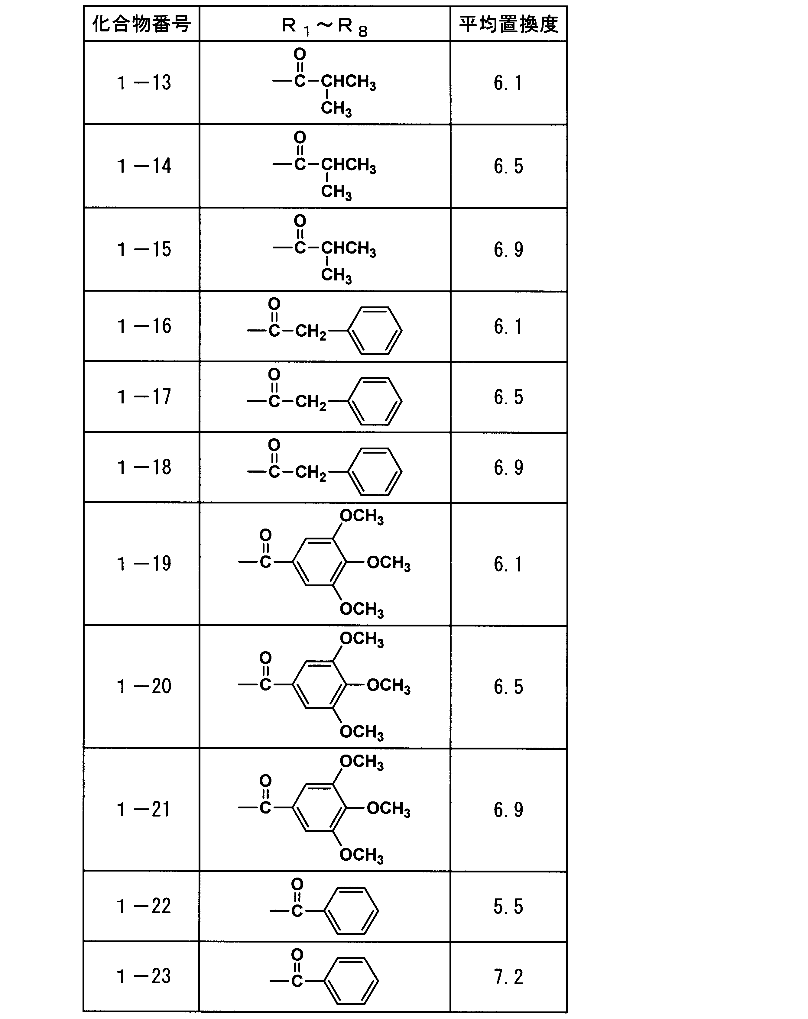
(合成例:本発明に用いられる化合物の合成)

撹拌装置、還流冷却器、温度計及び窒素ガス導入管を備えた四頭コルベンに、ショ糖34.2g(0.1モル)、無水安息香酸180.8g(0.8モル)、ピリジン379.7g(4.8モル)を仕込み、撹拌下に窒素ガス導入管から窒素ガスをバブリングさせながら昇温し、70℃で5時間エステル化反応を行った。次に、コルベン内を4×10²Pa以下に減圧し、60℃で過剰のピリジンを留去した後に、コルベン内を1.3×10Pa以下に減圧し、120℃まで昇温させ、無水安息香酸、生成した安息香酸の大部分を留去した。そして、次にトルエン1L、0.5質量%の炭酸ナトリウム水溶液300gを添加し、50℃で30分間撹拌後、静置して、トルエン層を分取した。最後に、分取したトルエン層に水100gを添加し、常温で30分間水洗後、トルエン層を分取し、減圧下(4×10²Pa以下)、60℃でトルエンを留去させ、化合物A-1、A-2、A-3、A-4及びA-5の混合物を得た。得られた混合物をHPLC及びLC-MASSで解析したところ、A-1が7質量%、A-2が58質量%、A-3が23質量%、A-4が9質量%、A-5が3質量%であった。なお、得られた混合物の一部をシリカゲルを用いたカラムクロマトグラフィーにより精製することで、それぞれ純度100%のA-1、A-2、A-3、A-4及びA-5を得た。
本発明でセルロースエステルフィルムに添加される、一般式(1)で表される化合物の総平均置換度は6.1~6.9の範囲であるが、当該置換度の範囲は4.0~8.0の範囲であることが好ましい。置換度分布は、エステル化反応時間の調節、又は置換度違いの化合物を混合することにより目的の置換度に調整してもよい。
(可塑剤)
本発明に係るλ/4位相差フィルムには、いわゆる可塑剤として知られる化合物を、機械的性質向上、柔軟性を付与、耐吸水性付与、水蒸気透過率低減、リターデーション調整等の目的で添加することが好ましく、例えばリン酸エステルやカルボン酸エステルが好ましく用いられる。
本発明に係るλ/4位相差フィルムには、いわゆる可塑剤として知られる化合物を、機械的性質向上、柔軟性を付与、耐吸水性付与、水蒸気透過率低減、リターデーション調整等の目的で添加することが好ましく、例えばリン酸エステルやカルボン酸エステルが好ましく用いられる。
可塑剤はλ/4位相差フィルム中に1~40質量%の範囲、特に1~30質量%の範囲含有することが好ましい。
リン酸エステルとしては、例えばトリフェニルホスフェート、トリクレジルホスフェート、フェニルジフェニルホスフェート等を挙げることができる。
カルボン酸エステルとしては、フタル酸エステル及びクエン酸エステル等、フタル酸エステルとしては、例えばジメチルフタレート、ジエチルホスフェート、ジオクチルフタレート及びジエチルヘキシルフタレート等、またクエン酸エステルとしてはクエン酸アセチルトリエチル及びクエン酸アセチルトリブチルを挙げることができる。またその他、オレイン酸ブチル、リシノール酸メチルアセチル、セバチン酸ジブチル、トリアセチン等も挙げられる。アルキルフタリルアルキルグリコレートもこの目的で好ましく用いられる。アルキルフタリルアルキルグリコレートのアルキルは炭素原子数1~8のアルキル基である。アルキルフタリルアルキルグリコレートとしてはメチルフタリルメチルグリコレート、エチルフタリルエチルグリコレート、プロピルフタリルプロピルグリコレート、ブチルフタリルブチルグリコレート、オクチルフタリルオクチルグリコレート、メチルフタリルエチルグリコレート、エチルフタリルメチルグリコレート、エチルフタリルプロピルグリコレート、プロピルフタリルエチルグリコレート、メチルフタリルプロピルグリコレート、メチルフタリルブチルグリコレート、エチルフタリルブチルグリコレート、ブチルフタリルメチルグリコレート、ブチルフタリルエチルグリコレート、プロピルフタリルブチルグリコレート、ブチルフタリルプロピルグリコレート、メチルフタリルオクチルグリコレート、エチルフタリルオクチルグリコレート、オクチルフタリルメチルグリコレート、オクチルフタリルエチルグリコレート等を挙げることができ、メチルフタリルメチルグリコレート、エチルフタリルエチルグリコレート、プロピルフタリルプロピルグリコレート、ブチルフタリルブチルグリコレート、オクチルフタリルオクチルグリコレートが好ましく用いられる。またこれらアルキルフタリルアルキルグリコレートを二種以上混合して使用してもよい。
また、可塑剤として特許第3793184号公報記載の下記化合物(CAE-1)~(CAE-3)で表されるクエン酸エステル系可塑剤を用いることも好ましい。



また、多価アルコールエステルも好ましく用いられる。
本発明に係るλ/4位相差フィルムに用いられる多価アルコールは次の一般式(a)で表される。
一般式(a):R1-(OH)n
ただし、R1はn価の有機基、nは2以上の正の整数、OH基はアルコール性、及び/又はフェノール性ヒドロキシ基(水酸基)を表す。
ただし、R1はn価の有機基、nは2以上の正の整数、OH基はアルコール性、及び/又はフェノール性ヒドロキシ基(水酸基)を表す。
多価アルコールエステル系可塑剤は2価以上の脂肪族多価アルコールとモノカルボン酸のエステルよりなる可塑剤であり、分子内に芳香環又はシクロアルキル環を有することが好ましい。好ましくは2~20価の脂肪族多価アルコールエステルである。
好ましい多価アルコールの例としては、例えば以下のようなものを挙げることができるが、本発明はこれらに限定されるものではない。アドニトール、アラビトール、エチレングリコール、ジエチレングリコール、トリエチレングリコール、テトラエチレングリコール、1,2-プロパンジオール、1,3-プロパンジオール、ジプロピレングリコール、トリプロピレングリコール、1,2-ブタンジオール、1,3-ブタンジオール、1,4-ブタンジオール、ジブチレングリコール、1,2,4-ブタントリオール、1,5-ペンタンジオール、1,6-ヘキサンジオール、ヘキサントリオール、ガラクチトール、マンニトール、3-メチルペンタン-1,3,5-トリオール、ピナコール、ソルビトール、トリメチロールプロパン、トリメチロールエタン、キシリトール等を挙げることができる。特に、トリエチレングリコール、テトラエチレングリコール、ジプロピレングリコール、トリプロピレングリコール、ソルビトール、トリメチロールプロパン、キシリトールが好ましい。
多価アルコールエステルに用いられるモノカルボン酸としては、特に制限はなく、公知の脂肪族モノカルボン酸、脂環族モノカルボン酸、芳香族モノカルボン酸等を用いることができる。脂環族モノカルボン酸、芳香族モノカルボン酸を用いると透湿性、保留性を向上させる点で好ましい。
好ましいモノカルボン酸の例としては以下のようなものを挙げることができるが、本発明はこれに限定されるものではない。
脂肪族モノカルボン酸としては、炭素数1~32の直鎖又は側鎖を有する脂肪酸を好ましく用いることができる。炭素数は1~20の範囲であることが更に好ましく、1~10の範囲であることが特に好ましい。酢酸を含有させるとセルロースエステルとの相溶性が増すため好ましく、酢酸と他のモノカルボン酸を混合して用いることも好ましい。
好ましい脂肪族モノカルボン酸としては、酢酸、プロピオン酸、酪酸、吉草酸、カプロン酸、エナント酸、カプリル酸、ペラルゴン酸、カプリン酸、2-エチル-ヘキサン酸、ウンデシル酸、ラウリン酸、トリデシル酸、ミリスチン酸、ペンタデシル酸、パルミチン酸、ヘプタデシル酸、ステアリン酸、ノナデカン酸、アラキン酸、ベヘン酸、リグノセリン酸、セロチン酸、ヘプタコサン酸、モンタン酸、メリシン酸、ラクセル酸等の飽和脂肪酸、ウンデシレン酸、オレイン酸、ソルビン酸、リノール酸、リノレン酸、アラキドン酸等の不飽和脂肪酸等を挙げることができる。
好ましい脂環族モノカルボン酸の例としては、シクロペンタンカルボン酸、シクロヘキサンカルボン酸、シクロオクタンカルボン酸、又はそれらの誘導体を挙げることができる。
好ましい芳香族モノカルボン酸の例としては、安息香酸、トルイル酸等の安息香酸のベンゼン環にアルキル基を導入したもの、ビフェニルカルボン酸、ナフタレンカルボン酸、テトラリンカルボン酸等のベンゼン環を2個以上有する芳香族モノカルボン酸、又はそれらの誘導体を挙げることができる。特に安息香酸が好ましい。
多価アルコールエステルの分子量は特に制限はないが、300~1500の範囲であることが好ましく、350~750の範囲であることが更に好ましい。分子量が大きい方が揮発し難くなるため好ましく、透湿性、セルロースエステルとの相溶性の点では小さい方が好ましい。
多価アルコールエステルに用いられるカルボン酸は一種類でもよいし、二種以上の混合であってもよい。また、多価アルコール中のOH基は、全てエステル化してもよいし、一部をOH基のままで残してもよい。
本発明に用いられる多価アルコールエステル系可塑剤の具体例は、特開2006-113239号公報段落〔0058〕~〔0061〕〕を参照することができる。
本発明に用いられる多価アルコールエステル系可塑剤の具体例は、特開2006-113239号公報段落〔0058〕~〔0061〕〕を参照することができる。
本発明に用いられる多価アルコールエステル系可塑剤は、セルロースエステルに対して1~30質量%の範囲、好ましくは1~20質量%の範囲となるように含まれていることが好ましい。また、延伸及び乾燥中のブリードアウト等を抑制させるため、200℃における蒸気圧が1400Pa以下の化合物であることが好ましい。
本発明に用いられる多価アルコールエステル系可塑剤は、セルロースエステル溶液の調製の際に、セルロースエステルや溶媒と共に添加してもよいし、溶液調製中や調製後に添加してもよい。
更に本発明では、下記一般式(b)で表される芳香族末端エステル系可塑剤を用いることが好ましい。
一般式(b):B-(G-A)n-G-B
(式中、Bはベンゼンモノカルボン酸残基、Gは炭素数2~12のアルキレングリコール残基又は炭素数6~12のアリールグリコール残基又は炭素数が4~12のオキシアルキレングリコール残基、Aは炭素数4~12のアルキレンジカルボン酸残基又は炭素数6~12のアリールジカルボン酸残基を表し、またnは1以上の整数を表す。)
一般式(b)中、Bで示されるベンゼンモノカルボン酸残基とGで示されるアルキレングリコール残基又はオキシアルキレングリコール残基又はアリールグリコール残基、Aで示されるアルキレンジカルボン酸残基又はアリールジカルボン酸残基とから構成されるものであり、通常のポリエステル系可塑剤と同様の反応により得られる。
(式中、Bはベンゼンモノカルボン酸残基、Gは炭素数2~12のアルキレングリコール残基又は炭素数6~12のアリールグリコール残基又は炭素数が4~12のオキシアルキレングリコール残基、Aは炭素数4~12のアルキレンジカルボン酸残基又は炭素数6~12のアリールジカルボン酸残基を表し、またnは1以上の整数を表す。)
一般式(b)中、Bで示されるベンゼンモノカルボン酸残基とGで示されるアルキレングリコール残基又はオキシアルキレングリコール残基又はアリールグリコール残基、Aで示されるアルキレンジカルボン酸残基又はアリールジカルボン酸残基とから構成されるものであり、通常のポリエステル系可塑剤と同様の反応により得られる。
本発明に用いられる芳香族末端エステル系可塑剤のベンゼンモノカルボン酸成分としては、例えば、安息香酸、パラターシャリブチル安息香酸、オルソトルイル酸、メタトルイル酸、パラトルイル酸、ジメチル安息香酸、エチル安息香酸、ノルマルプロピル安息香酸、アミノ安息香酸、アセトキシ安息香酸等があり、これらはそれぞれ一種又は二種以上の混合物として使用することができる。
本発明に用いられる芳香族末端エステル系可塑剤の炭素数2~12のアルキレングリコール成分としては、エチレングリコール、1,2-プロピレングリコール、1,3-プロピレングリコール、1,2-ブタンジオール、1,3-ブタンジオール、2-メチル-1,3-プロパンジオール、1,4-ブタンジオール、1,5-ペンタンジオール、2,2-ジメチル-1,3-プロパンジオール(ネオペンチルグリコール)、2,2-ジエチル-1,3-プロパンジオール(3,3-ジメチロ-ルペンタン)、2-n-ブチル-2-エチル-1,3プロパンジオール(3,3-ジメチロールヘプタン)、3-メチル-1,5-ペンタンジオール1,6-ヘキサンジオール、2,2,4-トリメチル-1,3-ペンタンジオール、2-エチル-1,3-ヘキサンジオール、2-メチル-1,8-オクタンジオール、1,9-ノナンジオール、1,10-デカンジオール、1,12-オクタデカンジオール等があり、これらのグリコールは、一種又は二種以上の混合物として使用される。
また、芳香族末端エステルの炭素数4~12のオキシアルキレングリコール成分としては、例えば、ジエチレングリコール、トリエチレングリコール、テトラエチレングリコール、ジプロピレングリコール、トリプロピレングリコール等があり、これらのグリコールは、一種又は二種以上の混合物として使用できる。
また、芳香族末端エステルの炭素数6~12のアリールグリコール成分としては、例えば、ハイドロキノン、レゾルシン、ビスフェノールA、ビスフェノールF、ビスフェノール等があり、これらのグリコールは、一種又は二種以上の混合物として使用できる。
芳香族末端エステルの炭素数4~12のアルキレンジカルボン酸成分としては、例えば、コハク酸、マレイン酸、フマール酸、グルタール酸、アジピン酸、アゼライン酸、セバシン酸、ドデカンジカルボン酸等があり、これらは、それぞれ一種又は二種以上の混合物として使用される。炭素数6~12のアリールジカルボン酸成分としては、フタル酸、テレフタル酸、1,5-ナフタレンジカルボン酸、1,4-ナフタレンジカルボン酸等がある。
芳香族末端エステル系可塑剤は、数平均分子量が、好ましくは300~2000の範囲、より好ましくは500~1500の範囲が好適である。また、その酸価は、0.5mgKOH/g以下、ヒドロキシ基(水酸基)価は25mgKOH/g以下、より好ましくは酸価0.3mgKOH/g以下、ヒドロキシ基(水酸基)価は15mgKOH/g以下のものが好適である。
〈芳香族末端エステルの酸価、ヒドロキシ基(水酸基)価〉
酸価とは、試料1g中に含まれる酸(分子末端に存在するカルボキシ基)を中和するために必要な水酸化カリウムのミリグラム数をいう。酸価及びヒドロキシ基(水酸基)価はJIS K0070(1992)に準拠して測定したものである。
酸価とは、試料1g中に含まれる酸(分子末端に存在するカルボキシ基)を中和するために必要な水酸化カリウムのミリグラム数をいう。酸価及びヒドロキシ基(水酸基)価はJIS K0070(1992)に準拠して測定したものである。
以下、本発明に用いられる芳香族末端エステル系可塑剤の合成例を示す。
〈サンプルNo.1(芳香族末端エステルサンプル)〉
反応容器に、フタル酸820部(5モル)、1,2-プロピレングリコール608部(8モル)、安息香酸610部(5モル)及び触媒としてテトライソプロピルチタネート0.30部を一括して仕込み窒素気流中で攪拌下、還流凝縮器を付して過剰の1価アルコールを還流させながら、酸価が2以下になるまで130~250℃の範囲で加熱を続け生成する水を連続的に除去した。次いで200~230℃の範囲で6.65×10³Pa~最終的に4×10²Pa以下の減圧下、留出分を除去し、この後濾過して次の性状を有する芳香族末端エステルを得た。
反応容器に、フタル酸820部(5モル)、1,2-プロピレングリコール608部(8モル)、安息香酸610部(5モル)及び触媒としてテトライソプロピルチタネート0.30部を一括して仕込み窒素気流中で攪拌下、還流凝縮器を付して過剰の1価アルコールを還流させながら、酸価が2以下になるまで130~250℃の範囲で加熱を続け生成する水を連続的に除去した。次いで200~230℃の範囲で6.65×10³Pa~最終的に4×10²Pa以下の減圧下、留出分を除去し、この後濾過して次の性状を有する芳香族末端エステルを得た。
粘度(25℃、mPa・s);19815
酸価 ;0.4
〈サンプルNo.2(芳香族末端エステルサンプル)〉
反応容器に、アジピン酸500部(3.5モル)、安息香酸305部(2.5モル)、ジエチレングリコール583部(5.5モル)及び触媒としてテトライソプロピルチタネート0.45部を用いる以外はサンプルNo.1と全く同様にして次の性状を有する芳香族末端エステルを得た。
酸価 ;0.4
〈サンプルNo.2(芳香族末端エステルサンプル)〉
反応容器に、アジピン酸500部(3.5モル)、安息香酸305部(2.5モル)、ジエチレングリコール583部(5.5モル)及び触媒としてテトライソプロピルチタネート0.45部を用いる以外はサンプルNo.1と全く同様にして次の性状を有する芳香族末端エステルを得た。
粘度(25℃、mPa・s);90
酸価 ;0.05
〈サンプルNo.3(芳香族末端エステルサンプル)〉
反応容器にフタル酸410部(2.5モル)、安息香酸610部(5モル)、ジプロピレングリコール737部(5.5モル)及び触媒としてテトライソプロピルチタネート0.40部を用いる以外はサンプルNo.1と全く同様にして次の性状を有する芳香族末端エステル系可塑剤を得た。
酸価 ;0.05
〈サンプルNo.3(芳香族末端エステルサンプル)〉
反応容器にフタル酸410部(2.5モル)、安息香酸610部(5モル)、ジプロピレングリコール737部(5.5モル)及び触媒としてテトライソプロピルチタネート0.40部を用いる以外はサンプルNo.1と全く同様にして次の性状を有する芳香族末端エステル系可塑剤を得た。
粘度(25℃、mPa・s);43400
酸価 ;0.2
本発明に用いられる芳香族末端エステル系可塑剤の具体例は、特開2009-192681号公報段落〔0123〕~〔0124〕〕を参照することができる。
酸価 ;0.2
本発明に用いられる芳香族末端エステル系可塑剤の具体例は、特開2009-192681号公報段落〔0123〕~〔0124〕〕を参照することができる。
本発明に用いられる芳香族末端エステル系可塑剤の含有量は、セルロースエステルフィルム中に1~20質量%の範囲含有することが好ましく、特に3~11質量%の範囲含有することが好ましい。
(ポリエステルポリオール)
本発明で使用されるポリエステルポリオールは、二塩基酸又はこれらのエステル形成性誘導体とグリコールとの縮合反応により得ることができる末端が水酸基となる重合体である。ここでいうエステル形成性誘導体とは、二塩基酸のエステル化物、二塩基酸クロライド、二塩基酸の無水物のことである。
(ポリエステルポリオール)
本発明で使用されるポリエステルポリオールは、二塩基酸又はこれらのエステル形成性誘導体とグリコールとの縮合反応により得ることができる末端が水酸基となる重合体である。ここでいうエステル形成性誘導体とは、二塩基酸のエステル化物、二塩基酸クロライド、二塩基酸の無水物のことである。
前記ポリエステルポリオールは、芳香族二塩基酸とグリコールとの脱水縮合反応、芳香族無水二塩基酸へのグリコールの付加及び脱水縮合反応、又は芳香族二塩基酸のエステル化物とグリコールとの脱アルコールによる縮合反応により得ることができる。
前記芳香族二塩基酸又はこれらのエステル形成性誘導体として、単独で10~16個の炭素原子を有する芳香族ジカルボン酸又はそのエステル形成性誘導体を使用できるが、例えばベンゼン環構造、ナフタレン環構造、アントラセン環構造等の芳香族環式構造を有するジカルボン酸やそのエステル形成性誘導体を使用することができ、例えば置換基を有するオルソフタル酸、置換基を有するイソフタル酸、置換基を有するテレフタル酸、置換基を有する無水フタル酸、1,4-ナフタレンジカルボン酸、2,3-ナフタレンジカルボン酸、2,6-ナフタレンジカルボン酸、2,7-ナフタレンジカルボン酸、1,8-ナフタレンジカルボン酸、2,6-アントラセンジカルボン酸等やこれらのエステル化物、及び酸塩化物、1,8-ナフタレンジカルボン酸の酸無水物等を挙げることができ、これらは芳香族環に置換基を有していても良く、これらを単独で使用又は二種以上併用できる。好ましくは、1,4-ナフタレンジカルボン酸、2,3-ナフタレンジカルボン酸、2,6-ナフタレンジカルボン酸、2,7-ナフタレンジカルボン酸、1,8-ナフタレンジカルボン酸及びそのエステル化物であり、更に好ましくは、2,3-ナフタレンジカルボン酸、2,6-ナフタレンジカルボン酸及びそのエステル化物であり、特に好ましくは、2,6-ナフタレンジカルボン酸及びそのエステル化物である。
前記ポリエステルポリオールの二塩基酸の炭素数の平均とは、単一の二塩基酸を用いてポリエステルポリオールを重合する場合は該二塩基酸の炭素数を意味するが、二種以上の二塩基酸を用いてポリエステルポリオールを重合する場合、それぞれの二塩基酸の炭素数とその二塩基酸のモル分率の積の合計を意味する。
本発明において、ポリエステルポリオールの原料として使用する二塩基酸の炭素数の平均が10~16の範囲であることが重要である。かかる二塩基酸の炭素数の平均が10以上であれば、リターデーションの発現性に優れ、炭素数の平均が16以下であれば、セルロースエステルとの相溶性が著しく優れる。二塩基酸として、好ましくは炭素数の平均が10~14であり、更に好ましくは炭素数の平均が10~12である。
前記炭素数の平均が10~16であれば、前記10~16個の炭素原子を有する芳香族二塩基酸とそれ以外の二塩基酸を併用することができる。
併用できる二塩基酸として、4~9個の炭素原子を有するジカルボン酸又はそのエステル形成性誘導体が好ましく、例えば、コハク酸、グルタル酸、アジピン酸、マレイン酸、無水コハク酸、無水マレイン酸、オルソフタル酸、イソフタル酸、テレフタル酸、無水フタル酸等やこれらのエステル化物、及び酸塩化物を挙げることができる。
前記グリコールとしては、例えばエチレングリコール、ジエチレングリコール、トリエチレングリコール、1,2-プロピレングリコール、1,3-プロパンジオール、2-メチル-1,3-プロパンジオール、1,2-ブタンジオール、1,3-ブタンジオール、1,4-ブタンジオール、2,3-ブタンジオール、1,5-ペンタンジオール、ネオペンチルグリコール、1,2-シクロペンタンジオール、1,3-シクロペンタンジオール、1,4-シクロヘキサンジオール等を単独で使用又は二種以上併用することができ、なかでもエチレングリコール、ジエチレングリコール、1,2-プロピレングリコール、2-メチル-1,3-プロパンジオールが好ましく、更に好ましくは、エチレングリコール、ジエチレングリコール、1,2-プロピレングリコールである。
本発明のポリエステルポリオールは、前記二塩基酸又はそれらのエステル形成性誘導体とグリコールを必要に応じてエステル化触媒の存在下で、例えば180~250℃の温度範囲内で、10~25時間、周知慣用の方法でエステル化反応させることによって製造することができる。
エステル化反応を行う際に、トルエン、キシレン等の溶媒を用いても良いが、無溶媒若しくは原料として使用するグリコールを溶媒として用いる方法が好ましい。
前記エステル化触媒としては、例えばテトライソプロピルチタネート、テトラブチルチタネート、p-トルエンスルホン酸、ジブチル錫オキサイド等を使用することができる。前記エステル化触媒は、二塩基酸又はそれらのエステル形成性誘導体の全量100質量部に対して0.01~0.5質量部の範囲使用することが好ましい。
二塩基酸又はそれらのエステル形成性誘導体とグリコールを反応させる際のモル比は、ポリエステルの末端基が水酸基となるモル比でなければならず、そのため二塩基酸又はそれらのエステル形成性誘導体1モルに対してグリコールは1.1~10モルである。好ましくは、二塩基酸又はそれらのエステル形成性誘導体1モルに対して、グリコールが1.5~7モルであり、更に好ましくは、二塩基酸又はそれらのエステル形成性誘導体1モルに対して、グリコールが2~5モルである。
一方、前記ポリエステルポリオール中に於けるカルボキシ基末端は、湿度安定性を低下させるため、その含有量は低い方が好ましい。具体的には、酸価5.0以下が好ましく、更に好ましくは1.0以下であり、特に好ましくは0.5以下である。
ここでいう酸価とは、試料1g中に含まれる酸(試料中に存在するカルボキシ基)を中和するために必要な水酸化カリウムのミリグラム数をいう。酸価はJIS K0070に準拠して測定したものである。
前記ポリエステルポリオールは、ヒドロキシ基(水酸基)価(OHV)が35~220mg/gの範囲であることが好ましい。ここでいうヒドロキシ基(水酸基)価とは、試料1g中に含まれるOH基をアセチル化したときに、ヒドロキシ基(水酸基)と結合した酢酸を中和するために要する水酸化カリウムのミリグラム数をいう。無水酢酸を用いて試料中のOH基をアセチル化し、使われなかった酢酸を水酸化カリウム溶液で滴定し、初期の無水酢酸の滴定値との差より求める。
前記ポリエステルポリオールのヒドロキシ基(水酸基)含有量は、70%以上であることが好ましい。ヒドロキシ基(水酸基)含有量が少ない場合、ポリエステルポリオールとセルロースエステルとの相溶性が低下する。このため、ヒドロキシ基(水酸基)含有量は、70%以上が好ましく、更に好ましくは90%以上であり、最も好ましくは99%以上である。
本発明において、ヒドロキシ基(水酸基)含有量が50%以下の化合物は、末端基の一方がヒドロキシ基(水酸基)以外の基で置換されているためポリエステルポリオールには含まれない。
前記ヒドロキシ基(水酸基)含有量は、下記の式(A)により求めることができる。
式(A):Y/X×100=ヒドロキシ基含有量(%)
X:前記ポリエステルポリオールのヒドロキシ基価(OHV)
Y:1/(数平均分子量(Mn))×56×2×1000
前記ポリエステルポリオールは、300~3000の範囲内の数平均分子量を有することが好ましく、350~2000の範囲の数平均分子量を有することがより好ましい。
X:前記ポリエステルポリオールのヒドロキシ基価(OHV)
Y:1/(数平均分子量(Mn))×56×2×1000
前記ポリエステルポリオールは、300~3000の範囲内の数平均分子量を有することが好ましく、350~2000の範囲の数平均分子量を有することがより好ましい。
また、本発明のポリエステルポリオールの分子量の分散度は1.0~3.0の範囲であることが好ましく、1.0~2.0の範囲であることが更に好ましい。分散度が上記範囲以内であれば、セルロースエステルとの相溶性に優れたポリエステルポリオールを得ることができる。
また、前記ポリエステルポリオールは、分子量が300~1800の範囲の成分を50%以上含有することが好ましい。数平均分子量を前記範囲とすることにより、相溶性を大幅に向上させることができる。
数平均分子量、分散度及び成分含有率を上記の好ましい範囲に制御する方法として、二塩基酸又はそれらのエステル形成性誘導体1モルに対してグリコールを2~5モル使用し、未反応のグリコールを減圧留去する方法が好ましい。減圧留去する温度は、100~200℃の範囲が好ましく、更に好ましくは120~180℃の範囲であり、特に好ましくは130~170℃の範囲が好ましい。減圧留去する際の減圧度は、0.1~500Torrの範囲が好ましく、更に好ましくは0.5~200Torrの範囲であり、最も好ましくは1~100Torrの範囲である。
ポリエステルポリオール数平均分子量(Mn)及び分散度は、ゲルパーミエーションクロマトグラフィー(GPC)を用いて測定することができる。
測定条件の一例は以下のとおりであるが、これに限られることはなく、同等の測定方法を用いることも可能である。
溶媒: テトラヒドロフラン(THF)
カラム: TSKgel G2000HXL(東ソー(株)製を2本接続して使用する)
カラム温度:40℃
試料濃度: 0.1質量%
装置: HLC-8220(東ソー(株)製)
流量: 1.0ml/min
校正曲線: PStQuick F(東ソー(株)製)による校正曲線を使用する。
カラム: TSKgel G2000HXL(東ソー(株)製を2本接続して使用する)
カラム温度:40℃
試料濃度: 0.1質量%
装置: HLC-8220(東ソー(株)製)
流量: 1.0ml/min
校正曲線: PStQuick F(東ソー(株)製)による校正曲線を使用する。
本発明の効果を得る上で、ポリエステルポリオールをフィルム中に5~30質量%の範囲含有することが好ましい。より好ましくは5~20質量%の範囲である。
以下に、炭素数が10~16である二塩基酸の具体例を示すが、本発明はこれに限定されない。
(1)2,6-ナフタレンジカルボン酸
(2)2,3-ナフタレンジカルボン酸
(3)2,6-アントラセンジカルボン酸
(4)2,6-ナフタレンジカルボン酸:コハク酸(75:25~99:1 モル比)
(5)2,6-ナフタレンジカルボン酸:テレフタル酸(50:50~99:1 モル比)
(6)2,3-ナフタレンジカルボン酸:コハク酸(75:25~99:1 モル比)
(7)2,3-ナフタレンジカルボン酸:テレフタル酸(50:50~99:1 モル比)
(8)2,6-アントラセンジカルボン酸:コハク酸(50:50~99:1 モル比)
(9)2,6-アントラセンジカルボン酸:テレフタル酸(25:75~99:1 モル比)
(10)2,6-ナフタレンジカルボン酸:アジピン酸(67:33~99:1 モル比)
(11)2,3-ナフタレンジカルボン酸:アジピン酸(67:33~99:1 モル比)
(12)2,6-アントラセンジカルボン酸:アジピン酸(40:60~99:1 モル比)
(紫外線吸収剤)
本発明に係るλ/4位相差フィルム及び光学フィルムには、紫外線吸収剤を含有させることができる。使用し得る紫外線吸収剤としては、例えば、オキシベンゾフェノン系化合物、ベンゾトリアゾール系化合物、サリチル酸エステル系化合物、ベンゾフェノン系化合物、シアノアクリレート系化合物、ニッケル錯塩系化合物、トリアジン系化合物等を挙げることができるが、着色の少ないベンゾトリアゾール系化合物が好ましい。また、特開平10-182621号、同8-337574号、特開2001-72782号記載の紫外線吸収剤、特開平6-148430号、特開2002-31715号、同2002-169020号、同2002-47357号、同2002-363420号、同2003-113317号記載の高分子紫外線吸収剤も好ましく用いられる。紫外線吸収剤としては、偏光子や液晶の劣化防止の観点から、波長370nm以下の紫外線の吸収能に優れており、かつ、液晶表示性の観点から、波長400nm以上の可視光の吸収が少ないものが好ましい。
(2)2,3-ナフタレンジカルボン酸
(3)2,6-アントラセンジカルボン酸
(4)2,6-ナフタレンジカルボン酸:コハク酸(75:25~99:1 モル比)
(5)2,6-ナフタレンジカルボン酸:テレフタル酸(50:50~99:1 モル比)
(6)2,3-ナフタレンジカルボン酸:コハク酸(75:25~99:1 モル比)
(7)2,3-ナフタレンジカルボン酸:テレフタル酸(50:50~99:1 モル比)
(8)2,6-アントラセンジカルボン酸:コハク酸(50:50~99:1 モル比)
(9)2,6-アントラセンジカルボン酸:テレフタル酸(25:75~99:1 モル比)
(10)2,6-ナフタレンジカルボン酸:アジピン酸(67:33~99:1 モル比)
(11)2,3-ナフタレンジカルボン酸:アジピン酸(67:33~99:1 モル比)
(12)2,6-アントラセンジカルボン酸:アジピン酸(40:60~99:1 モル比)
(紫外線吸収剤)
本発明に係るλ/4位相差フィルム及び光学フィルムには、紫外線吸収剤を含有させることができる。使用し得る紫外線吸収剤としては、例えば、オキシベンゾフェノン系化合物、ベンゾトリアゾール系化合物、サリチル酸エステル系化合物、ベンゾフェノン系化合物、シアノアクリレート系化合物、ニッケル錯塩系化合物、トリアジン系化合物等を挙げることができるが、着色の少ないベンゾトリアゾール系化合物が好ましい。また、特開平10-182621号、同8-337574号、特開2001-72782号記載の紫外線吸収剤、特開平6-148430号、特開2002-31715号、同2002-169020号、同2002-47357号、同2002-363420号、同2003-113317号記載の高分子紫外線吸収剤も好ましく用いられる。紫外線吸収剤としては、偏光子や液晶の劣化防止の観点から、波長370nm以下の紫外線の吸収能に優れており、かつ、液晶表示性の観点から、波長400nm以上の可視光の吸収が少ないものが好ましい。
本発明に有用な紫外線吸収剤の具体例として、2-(2′-ヒドロキシ-5′-メチルフェニル)ベンゾトリアゾール、2-(2′-ヒドロキシ-3′,5′-ジ-tert-ブチルフェニル)ベンゾトリアゾール、2-(2′-ヒドロキシ-3′-tert-ブチル-5′-メチルフェニル)ベンゾトリアゾール、2-(2′-ヒドロキシ-3′,5′-ジ-tert-ブチルフェニル)-5-クロロベンゾトリアゾール、2-(2′-ヒドロキシ-3′-(3″,4″,5″,6″-テトラヒドロフタルイミドメチル)-5′-メチルフェニル)ベンゾトリアゾール、2,2-メチレンビス(4-(1,1,3,3-テトラメチルブチル)-6-(2H-ベンゾトリアゾール-2-イル)フェノール)、2-(2′-ヒドロキシ-3′-tert-ブチル-5′-メチルフェニル)-5-クロロベンゾトリアゾール、2-(2H-ベンゾトリアゾール-2-イル)-6-(直鎖及び側鎖ドデシル)-4-メチルフェノール、オクチル-3-〔3-tert-ブチル-4-ヒドロキシ-5-(クロロ-2H-ベンゾトリアゾール-2-イル)フェニル〕プロピオネートと2-エチルヘキシル-3-〔3-tert-ブチル-4-ヒドロキシ-5-(5-クロロ-2H-ベンゾトリアゾール-2-イル)フェニル〕プロピオネートの混合物等を挙げることができるが、これらに限定されない。また、市販品として、チヌビン(TINUVIN)109、チヌビン(TINUVIN)171、チヌビン(TINUVIN)326(いずれもBASFジャパン社製)を好ましく使用できる。高分子紫外線吸収剤としては、大塚化学社製の反応型紫外線吸収剤RUVA-93を例として挙げることができる。
ベンゾフェノン系化合物の具体例として、2,4-ジヒドロキシベンゾフェノン、2,2′-ジヒドロキシ-4-メトキシベンゾフェノン、2-ヒドロキシ-4-メトキシ-5-スルホベンゾフェノン、ビス(2-メトキシ-4-ヒドロキシ-5-ベンゾイルフェニルメタン)等を挙げることができるが、これらに限定されない。
本発明で好ましく用いられる上記記載の紫外線吸収剤は、透明性が高く、偏光板や液晶素子の劣化を防ぐ効果に優れたベンゾトリアゾール系紫外線吸収剤やベンゾフェノン系紫外線吸収剤が好ましく、不要な着色がより少ないベンゾトリアゾール系紫外線吸収剤が特に好ましく用いられる。
紫外線吸収剤のドープへの添加方法は、ドープ中で紫外線吸収剤を溶解するようなものであれば制限なく使用できるが、本発明においては紫外線吸収剤をメチレンクロライド、酢酸メチル、ジオキソラン等のセルロースエステルに対する良溶媒、又は良溶媒と低級脂肪族アルコール(メタノール、エタノール、プロパノール、ブタノール等)のような貧溶媒との混合有機溶媒に溶解し紫外線吸収剤溶液としてセルロースエステル溶液に添加してドープとする方法が好ましい。この場合できるだけドープ溶媒組成と紫外線吸収剤溶液の溶媒組成とを同じとするか近づけることが好ましい。紫外線吸収剤の含有量は0.01~5質量%の範囲が好ましく、特に好ましくは0.5~3質量%の範囲である。
(酸化防止剤)
酸化防止剤としては、ヒンダードフェノール系の化合物が好ましく用いられ、例えば、2,6-ジ-t-ブチル-p-クレゾール、ペンタエリスリチル-テトラキス〔3-(3,5-ジ-t-ブチル-4-ヒドロキシフェニル)プロピオネート〕、トリエチレングリコール-ビス〔3-(3-t-ブチル-5-メチル-4-ヒドロキシフェニル)プロピオネート〕、1,6-ヘキサンジオール-ビス〔3-(3,5-ジ-t-ブチル-4-ヒドロキシフェニル)プロピオネート〕、2,4-ビス-(n-オクチルチオ)-6-(4-ヒドロキシ-3,5-ジ-t-ブチルアニリノ)-1,3,5-トリアジン、2,2-チオ-ジエチレンビス〔3-(3,5-ジ-t-ブチル-4-ヒドロキシフェニル)プロピオネート〕、オクタデシル-3-(3,5-ジ-t-ブチル-4-ヒドロキシフェニル)プロピオネート、N,N′-ヘキサメチレンビス(3,5-ジ-t-ブチル-4-ヒドロキシ-ヒドロシンナマミド)、1,3,5-トリメチル-2,4,6-トリス(3,5-ジ-t-ブチル-4-ヒドロキシベンジル)ベンゼン、トリス-(3,5-ジ-t-ブチル-4-ヒドロキシベンジル)-イソシアヌレイト等が挙げられる。特に2,6-ジ-t-ブチル-p-クレゾール、ペンタエリスリチル-テトラキス〔3-(3,5-ジ-t-ブチル-4-ヒドロキシフェニル)プロピオネート〕、トリエチレングリコール-ビス〔3-(3-t-ブチル-5-メチル-4-ヒドロキシフェニル)プロピオネート〕が好ましい。また例えば、N,N′-ビス〔3-(3,5-ジ-t-ブチル-4-ヒドロキシフェニル)プロピオニル〕ヒドラジン等のヒドラジン系の金属不活性剤やトリス(2,4-ジ-t-ブチルフェニル)フォスファイト等のリン系加工安定剤を併用してもよい。
酸化防止剤としては、ヒンダードフェノール系の化合物が好ましく用いられ、例えば、2,6-ジ-t-ブチル-p-クレゾール、ペンタエリスリチル-テトラキス〔3-(3,5-ジ-t-ブチル-4-ヒドロキシフェニル)プロピオネート〕、トリエチレングリコール-ビス〔3-(3-t-ブチル-5-メチル-4-ヒドロキシフェニル)プロピオネート〕、1,6-ヘキサンジオール-ビス〔3-(3,5-ジ-t-ブチル-4-ヒドロキシフェニル)プロピオネート〕、2,4-ビス-(n-オクチルチオ)-6-(4-ヒドロキシ-3,5-ジ-t-ブチルアニリノ)-1,3,5-トリアジン、2,2-チオ-ジエチレンビス〔3-(3,5-ジ-t-ブチル-4-ヒドロキシフェニル)プロピオネート〕、オクタデシル-3-(3,5-ジ-t-ブチル-4-ヒドロキシフェニル)プロピオネート、N,N′-ヘキサメチレンビス(3,5-ジ-t-ブチル-4-ヒドロキシ-ヒドロシンナマミド)、1,3,5-トリメチル-2,4,6-トリス(3,5-ジ-t-ブチル-4-ヒドロキシベンジル)ベンゼン、トリス-(3,5-ジ-t-ブチル-4-ヒドロキシベンジル)-イソシアヌレイト等が挙げられる。特に2,6-ジ-t-ブチル-p-クレゾール、ペンタエリスリチル-テトラキス〔3-(3,5-ジ-t-ブチル-4-ヒドロキシフェニル)プロピオネート〕、トリエチレングリコール-ビス〔3-(3-t-ブチル-5-メチル-4-ヒドロキシフェニル)プロピオネート〕が好ましい。また例えば、N,N′-ビス〔3-(3,5-ジ-t-ブチル-4-ヒドロキシフェニル)プロピオニル〕ヒドラジン等のヒドラジン系の金属不活性剤やトリス(2,4-ジ-t-ブチルフェニル)フォスファイト等のリン系加工安定剤を併用してもよい。
これらの化合物の添加量は、セルロースエステルに対して質量割合で1ppm~1.0%の範囲が好ましく、10~1000ppmの範囲が更に好ましい。
また、下記一般式(L)で表される化合物を用いることも好ましい。
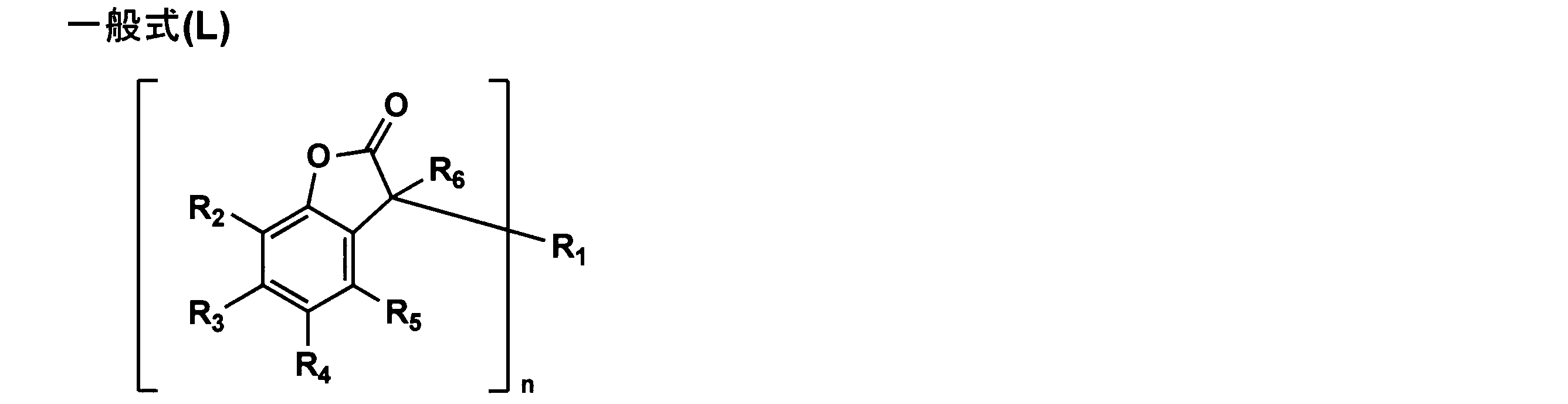
〔式中、R2~R5は各々互いに独立して水素原子又は置換基を表し、R6は水素原子又は置換基を表し、nは1又は2を表す。nが1であるとき、R1は置換基を表し、nが2であるとき、R1は2価の連結基を表す。〕
前記一般式(L)において、R2~R5は各々互いに独立して水素原子又は置換基を表す。R2~R5で表される置換基は、特に制限はないが、例えば、アルキル基(例えば、メチル基、エチル基、プロピル基、イソプロピル基、t-ブチル基、ペンチル基、ヘキシル基、オクチル基、ドデシル基、トリフルオロメチル基等)、シクロアルキル基(例えば、シクロペンチル基、シクロヘキシル基等)、アリール基(例えば、フェニル基、ナフチル基等)、アシルアミノ基(例えば、アセチルアミノ基、ベンゾイルアミノ基等)、アルキルチオ基(例えば、メチルチオ基、エチルチオ基等)、アリールチオ基(例えば、フェニルチオ基、ナフチルチオ基等)、アルケニル基(例えば、ビニル基、2-プロペニル基、3-ブテニル基、1-メチル-3-プロペニル基、3-ペンテニル基、1-メチル-3-ブテニル基、4-ヘキセニル基、シクロヘキセニル基等)、ハロゲン原子(例えば、フッ素原子、塩素原子、臭素原子、沃素原子等)、アルキニル基(例えば、プロパルギル基等)、複素環基(例えば、ピリジル基、チアゾリル基、オキサゾリル基、イミダゾリル基等)、アルキルスルホニル基(例えば、メチルスルホニル基、エチルスルホニル基等)、アリールスルホニル基(例えば、フェニルスルホニル基、ナフチルスルホニル基等)、アルキルスルフィニル基(例えば、メチルスルフィニル基等)、アリールスルフィニル基(例えば、フェニルスルフィニル基等)、ホスホノ基、アシル基(例えば、アセチル基、ピバロイル基、ベンゾイル基等)、カルバモイル基(例えば、アミノカルボニル基、メチルアミノカルボニル基、ジメチルアミノカルボニル基、ブチルアミノカルボニル基、シクロヘキシルアミノカルボニル基、フェニルアミノカルボニル基、2-ピリジルアミノカルボニル基等)、スルファモイル基(例えば、アミノスルホニル基、メチルアミノスルホニル基、ジメチルアミノスルホニル基、ブチルアミノスルホニル基、ヘキシルアミノスルホニル基、シクロヘキシルアミノスルホニル基、オクチルアミノスルホニル基、ドデシルアミノスルホニル基、フェニルアミノスルホニル基、ナフチルアミノスルホニル基、2-ピリジルアミノスルホニル基等)、スルホンアミド基(例えば、メタンスルホンアミド基、ベンゼンスルホンアミド基等)、シアノ基、アルコキシ基(例えば、メトキシ基、エトキシ基、プロポキシ基等)、アリールオキシ基(例えば、フェノキシ基、ナフチルオキシ基等)、複素環オキシ基、シロキシ基、アシルオキシ基(例えば、アセチルオキシ基、ベンゾイルオキシ基等)、スルホン酸基、スルホン酸の塩、アミノカルボニルオキシ基、アミノ基(例えば、アミノ基、エチルアミノ基、ジメチルアミノ基、ブチルアミノ基、シクロペンチルアミノ基、2-エチルヘキシルアミノ基、ドデシルアミノ基等)、アニリノ基(例えば、フェニルアミノ基、クロロフェニルアミノ基、トルイジノ基、アニシジノ基、ナフチルアミノ基、2-ピリジルアミノ基等)、イミド基、ウレイド基(例えば、メチルウレイド基、エチルウレイド基、ペンチルウレイド基、シクロヘキシルウレイド基、オクチルウレイド基、ドデシルウレイド基、フェニルウレイド基、ナフチルウレイド基、2-ピリジルアミノウレイド基等)、アルコキシカルボニルアミノ基(例えば、メトキシカルボニルアミノ基、フェノキシカルボニルアミノ基等)、アルコキシカルボニル基(例えば、メトキシカルボニル基、エトキシカルボニル基、フェノキシカルボニル等)、アリールオキシカルボニル基(例えば、フェノキシカルボニル基等)、複素環チオ基、チオウレイド基、カルボキシ基、カルボン酸の塩、ヒドロキシ基、メルカプト基、ニトロ基等の各基が挙げられる。これらの置換基は同様の置換基によって更に置換されていてもよい。
前記一般式(L)において、R2~R5は各々互いに独立して水素原子又は置換基を表す。R2~R5で表される置換基は、特に制限はないが、例えば、アルキル基(例えば、メチル基、エチル基、プロピル基、イソプロピル基、t-ブチル基、ペンチル基、ヘキシル基、オクチル基、ドデシル基、トリフルオロメチル基等)、シクロアルキル基(例えば、シクロペンチル基、シクロヘキシル基等)、アリール基(例えば、フェニル基、ナフチル基等)、アシルアミノ基(例えば、アセチルアミノ基、ベンゾイルアミノ基等)、アルキルチオ基(例えば、メチルチオ基、エチルチオ基等)、アリールチオ基(例えば、フェニルチオ基、ナフチルチオ基等)、アルケニル基(例えば、ビニル基、2-プロペニル基、3-ブテニル基、1-メチル-3-プロペニル基、3-ペンテニル基、1-メチル-3-ブテニル基、4-ヘキセニル基、シクロヘキセニル基等)、ハロゲン原子(例えば、フッ素原子、塩素原子、臭素原子、沃素原子等)、アルキニル基(例えば、プロパルギル基等)、複素環基(例えば、ピリジル基、チアゾリル基、オキサゾリル基、イミダゾリル基等)、アルキルスルホニル基(例えば、メチルスルホニル基、エチルスルホニル基等)、アリールスルホニル基(例えば、フェニルスルホニル基、ナフチルスルホニル基等)、アルキルスルフィニル基(例えば、メチルスルフィニル基等)、アリールスルフィニル基(例えば、フェニルスルフィニル基等)、ホスホノ基、アシル基(例えば、アセチル基、ピバロイル基、ベンゾイル基等)、カルバモイル基(例えば、アミノカルボニル基、メチルアミノカルボニル基、ジメチルアミノカルボニル基、ブチルアミノカルボニル基、シクロヘキシルアミノカルボニル基、フェニルアミノカルボニル基、2-ピリジルアミノカルボニル基等)、スルファモイル基(例えば、アミノスルホニル基、メチルアミノスルホニル基、ジメチルアミノスルホニル基、ブチルアミノスルホニル基、ヘキシルアミノスルホニル基、シクロヘキシルアミノスルホニル基、オクチルアミノスルホニル基、ドデシルアミノスルホニル基、フェニルアミノスルホニル基、ナフチルアミノスルホニル基、2-ピリジルアミノスルホニル基等)、スルホンアミド基(例えば、メタンスルホンアミド基、ベンゼンスルホンアミド基等)、シアノ基、アルコキシ基(例えば、メトキシ基、エトキシ基、プロポキシ基等)、アリールオキシ基(例えば、フェノキシ基、ナフチルオキシ基等)、複素環オキシ基、シロキシ基、アシルオキシ基(例えば、アセチルオキシ基、ベンゾイルオキシ基等)、スルホン酸基、スルホン酸の塩、アミノカルボニルオキシ基、アミノ基(例えば、アミノ基、エチルアミノ基、ジメチルアミノ基、ブチルアミノ基、シクロペンチルアミノ基、2-エチルヘキシルアミノ基、ドデシルアミノ基等)、アニリノ基(例えば、フェニルアミノ基、クロロフェニルアミノ基、トルイジノ基、アニシジノ基、ナフチルアミノ基、2-ピリジルアミノ基等)、イミド基、ウレイド基(例えば、メチルウレイド基、エチルウレイド基、ペンチルウレイド基、シクロヘキシルウレイド基、オクチルウレイド基、ドデシルウレイド基、フェニルウレイド基、ナフチルウレイド基、2-ピリジルアミノウレイド基等)、アルコキシカルボニルアミノ基(例えば、メトキシカルボニルアミノ基、フェノキシカルボニルアミノ基等)、アルコキシカルボニル基(例えば、メトキシカルボニル基、エトキシカルボニル基、フェノキシカルボニル等)、アリールオキシカルボニル基(例えば、フェノキシカルボニル基等)、複素環チオ基、チオウレイド基、カルボキシ基、カルボン酸の塩、ヒドロキシ基、メルカプト基、ニトロ基等の各基が挙げられる。これらの置換基は同様の置換基によって更に置換されていてもよい。
前記一般式(L)において、R2~R5は、水素原子又はアルキル基が好ましい。
前記一般式(L)において、R6は水素原子又は置換基を表し、R6で表される置換基は、R2~R5が表す置換基と同様な基を挙げることができる。
前記一般式(L)において、R6は水素原子が好ましい。
前記一般式(L)において、nは1又は2を表す。
前記一般式(L)において、nが1であるとき、R1は置換基を表し、nが2であるとき、R1は2価の連結基を表す。R1が置換基を表すとき、置換基としては、R2~R5が表す置換基と同様な基を挙げることができる。R1は2価の連結基を表すとき、2価の連結基として例えば、置換基を有しても良いアルキレン基、置換基を有しても良いアリーレン基、酸素原子、窒素原子、硫黄原子、あるいはこれらの連結基の組み合わせを挙げることができる。
前記一般式(L)において、nは1が好ましく、その時のR1は置換又は無置換のフェニル基が好ましく、アルキル基が置換したフェニル基が更に好ましい。
前記一般式(L)で表される化合物の具体例は、特開2009-109721号公報段落〔0070〕~〔0083〕を参照することができる。
前記一般式(L)で表される化合物は、それぞれ一種あるいは二種以上組み合わせて用いることができ、その配合量は本発明の目的を損なわない範囲で適宜選択されるが、セルロースエステル100質量部に対して、通常0.001~10.0質量部の範囲、好ましくは0.01~5.0質量部の範囲、更に好ましくは、0.1~3.0質量部の範囲である。
(リターデーション調整剤)
リターデーションを調整するために添加する化合物は、欧州特許911,656A2号明細書に記載されているような、二つ以上の芳香族環を有する芳香族化合物を使用することができる。
リターデーションを調整するために添加する化合物は、欧州特許911,656A2号明細書に記載されているような、二つ以上の芳香族環を有する芳香族化合物を使用することができる。
また二種類以上の芳香族化合物を併用してもよい。該芳香族化合物の芳香族環には、芳香族炭化水素環に加えて、芳香族性ヘテロ環を含む。芳香族性ヘテロ環であることが特に好ましく、芳香族性ヘテロ環は一般に、不飽和ヘテロ環である。中でも1,3,5-トリアジン環が特に好ましい。
芳香族化合物が有する芳香族環の数は2~20であることが好ましく、2~12であることがより好ましく、2~8であることが更に好ましく、3~6であることが最も好ましい。二つの芳香族環の結合関係は、(a)縮合環を形成する場合、(b)単結合で直結する場合及び(c)連結基を介して結合する場合に分類できる(芳香族環のため、スピロ結合は形成できない)。結合関係は、(a)~(c)のいずれでもよい。
(a)の縮合環(二つ以上の芳香族環の縮合環)の例には、インデン環、ナフタレン環、アズレン環、フルオレン環、フェナントレン環、アントラセン環、アセナフチレン環、ナフタセン環、ピレン環、インドール環、イソインドール環、ベンゾフラン環、ベンゾチオフェン環、インドリジン環、ベンゾオキサゾール環、ベンゾチアゾール環、ベンゾイミダゾール環、ベンゾトリアゾール環、プリン環、インダゾール環、クロメン環、キノリン環、イソキノリン環、キノリジン環、キナゾリン環、シンノリン環、キノキサリン環、フタラジン環、プテリジン環、カルバゾール環、アクリジン環、フェナントリジン環、キサンテン環、フェナジン環、フェノチアジン環、フェノキサチイン環、フェノキサジン環及びチアントレン環が含まれる。ナフタレン環、アズレン環、インドール環、ベンゾオキサゾール環、ベンゾチアゾール環、ベンゾイミダゾール環、ベンゾトリアゾール環及びキノリン環が好ましい。
(b)の単結合は、二つの芳香族環の炭素原子間の結合であることが好ましい。二以上の単結合で二つの芳香族環を結合して、二つの芳香族環の間に脂肪族環又は非芳香族性複素環を形成してもよい。
(c)の連結基も二つの芳香族環の炭素原子と結合することが好ましい。連結基は、アルキレン基、アルケニレン基、アルキニレン基、-CO-、-O-、-NH-、-S-又はそれらの組み合わせであることが好ましい。組み合わせからなる連結基の例を以下に示す。なお、以下の連結基の例の左右の関係は、逆になってもよい。
-CO-O-、-CO-NH-、-アルキレン-O-、-NH-CO-NH-、-NH-CO-O-、-O-CO-O-、-O-アルキレン-O-、-CO-アルケニレン-、-CO-アルケニレン-NH-、-CO-アルケニレン-O-、-アルキレン-CO-O-アルキレン-O-CO-アルキレン-、-O-アルキレン-CO-O-アルキレン-O-CO-アルキレン-O-、-O-CO-アルキレン-CO-O-、-NH-CO-アルケニレン-、-O-CO-アルケニレン-。
芳香族環及び連結基は置換基を有していてもよい。置換基の例には、ハロゲン原子(F、Cl、Br、I)、ヒドロキシ、カルボキシ、シアノ、アミノ、ニトロ、スルホ、カルバモイル、スルファモイル、ウレイド、アルキル基、アルケニル基、アルキニル基、脂肪族アシル基、脂肪族アシルオキシ基、アルコキシ基、アルコキシカルボニル基、アルコキシカルボニルアミノ基、アルキルチオ基、アルキルスルホニル基、脂肪族アミド基、脂肪族スルホンアミド基、脂肪族置換アミノ基、脂肪族置換カルバモイル基、脂肪族置換スルファモイル基、脂肪族置換ウレイド基及び非芳香族性複素環基が含まれる。
アルキル基の炭素原子数は1~8であることが好ましい。環状アルキル基よりも鎖状アルキル基の方が好ましく、直鎖状アルキル基が特に好ましい。アルキル基は、更に置換基(例、ヒドロキシ、カルボキシ、アルコキシ基、アルキル置換アミノ基)を有していてもよい。アルキル基の(置換アルキル基を含む)例には、メチル、エチル、n-ブチル、n-ヘキシル、2-ヒドロキシエチル、4-カルボキシブチル、2-メトキシエチル及び2-ジエチルアミノエチルが含まれる。アルケニル基の炭素原子数は、2~8であることが好ましい。環状アルケニル基よりも鎖状アルケニル基の方が好ましく、直鎖状アルケニル基が特に好ましい。アルケニル基は、更に置換基を有していてもよい。アルケニル基の例には、ビニル、アリル及び1-ヘキセニルが含まれる。アルキニル基の炭素原子数は、2~8であることが好ましい。環状アルキニル基よりも鎖状アルキニル基の方が好ましく、直鎖状アルキニル基が特に好ましい。アルキニル基は、更に置換基を有していてもよい。アルキニル基の例には、エチニル、1-ブチニル及び1-ヘキシニルが含まれる。
脂肪族アシル基の炭素原子数は1~10であることが好ましい。脂肪族アシル基の例には、アセチル、プロパノイル及びブタノイルが含まれる。脂肪族アシルオキシ基の炭素原子数は、1~10であることが好ましい。脂肪族アシルオキシ基の例には、アセトキシが含まれる。アルコキシ基の炭素原子数は1~8であることが好ましい。アルコキシ基は、更に置換基(例、アルコキシ基)を有していてもよい。アルコキシ基の(置換アルコキシ基を含む)例には、メトキシ、エトキシ、ブトキシ及びメトキシエトキシが含まれる。アルコキシカルボニル基の炭素原子数は2~10であることが好ましい。アルコキシカルボニル基の例には、メトキシカルボニル及びエトキシカルボニルが含まれる。アルコキシカルボニルアミノ基の炭素原子数は、2~10であることが好ましい。アルコキシカルボニルアミノ基の例には、メトキシカルボニルアミノ及びエトキシカルボニルアミノが含まれる。
アルキルチオ基の炭素原子数は1~12であることが好ましい。アルキルチオ基の例には、メチルチオ、エチルチオ及びオクチルチオが含まれる。アルキルスルホニル基の炭素原子数は、1~8であることが好ましい。アルキルスルホニル基の例には、メタンスルホニル及びエタンスルホニルが含まれる。脂肪族アミド基の炭素原子数は、1~10であることが好ましい。脂肪族アミド基の例には、アセトアミドが含まれる。脂肪族スルホンアミド基の炭素原子数は、1~8であることが好ましい。脂肪族スルホンアミド基の例には、メタンスルホンアミド、ブタンスルホンアミド及びn-オクタンスルホンアミドが含まれる。脂肪族置換アミノ基の炭素原子数は、1~10であることが好ましい。脂肪族置換アミノ基の例には、ジメチルアミノ、ジエチルアミノ及び2-カルボキシエチルアミノが含まれる。脂肪族置換カルバモイル基の炭素原子数は2~10であることが好ましい。脂肪族置換カルバモイル基の例には、メチルカルバモイル及びジエチルカルバモイルが含まれる。脂肪族置換スルファモイル基の炭素原子数は、1~8であることが好ましい。脂肪族置換スルファモイル基の例には、メチルスルファモイル及びジエチルスルファモイルが含まれる。脂肪族置換ウレイド基の炭素原子数は、2~10であることが好ましい。脂肪族置換ウレイド基の例には、メチルウレイドが含まれる。非芳香族性複素環基の例には、ピペリジノ及びモルホリノが含まれる。
リターデーション調整剤の分子量は、300以上800以下であることが好ましい。これは、使用時及び偏光板加工時における流出抑制の観点から、任意に分子構造の極性を選択することができる。
1,3,5-トリアジン環を有する化合物は、中でも、下記一般式(R)で表される化合物が好ましい。

一般式(R)において、X1は、単結合、-NR4-、-O-又は-S-であり;X2は単結合、-NR5-、-O-又は-S-であり;X3は単結合、-NR6-、-O-又は-S-であり;R1、R2及びR3はアルキル基、アルケニル基、アリール基又は複素環基であり;そして、R4、R5及びR6は、水素原子、アルキル基、アルケニル基、アリール基又は複素環基である。一般式(R)で表される化合物は、メラミン化合物であることが特に好ましい。
メラミン化合物では、一般式(R)において、X1、X2及びX3が、それぞれ、-NR4-、-NR5-及び-NR6-であるか、あるいは、X1、X2及びX3が単結合であり、かつ、R1、R2及びR3が窒素原子に遊離原子価を持つ複素環基である。-X1-R1、-X2-R2及び-X3-R3は、同一の置換基であることが好ましい。R1、R2及びR3は、アリール基であることが特に好ましい。R4、R5及びR6は、水素原子であることが特に好ましい。
上記アルキル基は、環状アルキル基よりも鎖状アルキル基である方が好ましい。分岐を有する鎖状アルキル基よりも、直鎖状アルキル基の方が好ましい。
アルキル基の炭素原子数は、1~30であることが好ましく、1~20であることがより好ましく、1~10であることが更に好ましく、1~8であることが更にまた好ましく、1~6であることが最も好ましい。アルキル基は置換基を有していてもよい。
置換基の具体例としては、例えばハロゲン原子、アルコキシ基(例えばメトキシ、エトキシ、エポキシエチルオキシ等の各基)及びアシルオキシ基(例えば、アクリロイルオキシ、メタクリロイルオキシ)等が挙げられる。上記アルケニル基は、環状アルケニル基よりも鎖状アルケニル基である方が好ましい。分岐を有する鎖状アルケニル基よりも、直鎖状アルケニル基の方が好ましい。アルケニル基の炭素原子数は、2~30であることが好ましく、2~20であることがより好ましく、2~10であることが更に好ましく、2~8であることが更にまた好ましく、2~6であることが最も好ましい。アルケニル基は、置換基を有していてもよい。
置換基の具体例としては、ハロゲン原子、アルコキシ基(例えば、メトキシ、エトキシ、エポキシエチルオキシ等の各基)又はアシルオキシ基(例えば、アクリロイルオキシ、メタクリロイルオキシ等の各基)が挙げられる。
上記アリール基は、フェニル基又はナフチル基であることが好ましく、フェニル基であることが特に好ましい。アリール基は置換基を有していてもよい。
置換基の具体例としては、例えば、ハロゲン原子、ヒドロキシ、シアノ、ニトロ、カルボキシ、アルキル基、アルケニル基、アリール基、アルコキシ基、アルケニルオキシ基、アリールオキシ基、アシルオキシ基、アルコキシカルボニル基、アルケニルオキシカルボニル基、アリールオキシカルボニル基、スルファモイル、アルキル置換スルファモイル基、アルケニル置換スルファモイル基、アリール置換スルファモイル基、スルホンアミド基、カルバモイル、アルキル置換カルバモイル基、アルケニル置換カルバモイル基、アリール置換カルバモイル基、アミド基、アルキルチオ基、アルケニルチオ基、アリールチオ基及びアシル基が含まれる。上記アルキル基は、前述したアルキル基と同義である。
アルコキシ基、アシルオキシ基、アルコキシカルボニル基、アルキル置換スルファモイル基、スルホンアミド基、アルキル置換カルバモイル基、アミド基、アルキルチオ基とアシル基のアルキル部分も、前述したアルキル基と同義である。
上記アルケニル基は、前述したアルケニル基と同義である。
アルケニルオキシ基、アシルオキシ基、アルケニルオキシカルボニル基、アルケニル置換スルファモイル基、スルホンアミド基、アルケニル置換カルバモイル基、アミド基、アルケニルチオ基及びアシル基のアルケニル部分も、前述したアルケニル基と同義である。
上記アリール基の具体例としては、例えば、フェニル、α-ナフチル、β-ナフチル、4-メトキシフェニル、3,4-ジエトキシフェニル、4-オクチルオキシフェニル又は4-ドデシルオキシフェニル等の各基が挙げられる。
アリールオキシ基、アシルオキシ基、アリールオキシカルボニル基、アリール置換スルファモイル基、スルホンアミド基、アリール置換カルバモイル基、アミド基、アリールチオ基及びアシル基の部分の例は、上記アリール基と同義である。
X1、X2又はX3が-NR-、-O-又は-S-である場合の複素環基は、芳香族性を有することが好ましい。
芳香族性を有する複素環基中の複素環としては、一般に不飽和複素環であり、好ましくは最多の二重結合を有する複素環である。複素環は、5員環、6員環又は7員環であることが好ましく、5員環又は6員環であることが更に好ましく、6員環であることが最も好ましい。
複素環中のヘテロ原子は、N、S又はO等の各原子であることが好ましく、N原子であることが特に好ましい。
芳香族性を有する複素環としては、ピリジン環(複素環基としては、例えば、2-ピリジル又は4-ピリジル等の各基)が特に好ましい。複素環基は、置換基を有していてもよい。複素環基の置換基の例は、上記アリール部分の置換基の例と同様である。
X1、X2又はX3が単結合である場合の複素環基は、窒素原子に遊離原子価を持つ複素環基であることが好ましい。窒素原子に遊離原子価を持つ複素環基は、5員環、6員環又は7員環であることが好ましく、5員環又は6員環であることが更に好ましく、5員環であることが最も好ましい。複素環基は、複数の窒素原子を有していてもよい。
また、複素環基中のヘテロ原子は、窒素原子以外のヘテロ原子(例えば、O原子、S原子)を有していてもよい。複素環基は、置換基を有していてもよい。複素環基の置換基の具体例は、上記アリール部分の置換基の具体例と同義である。
以下に、窒素原子に遊離原子価を持つ複素環基の具体例を示す。
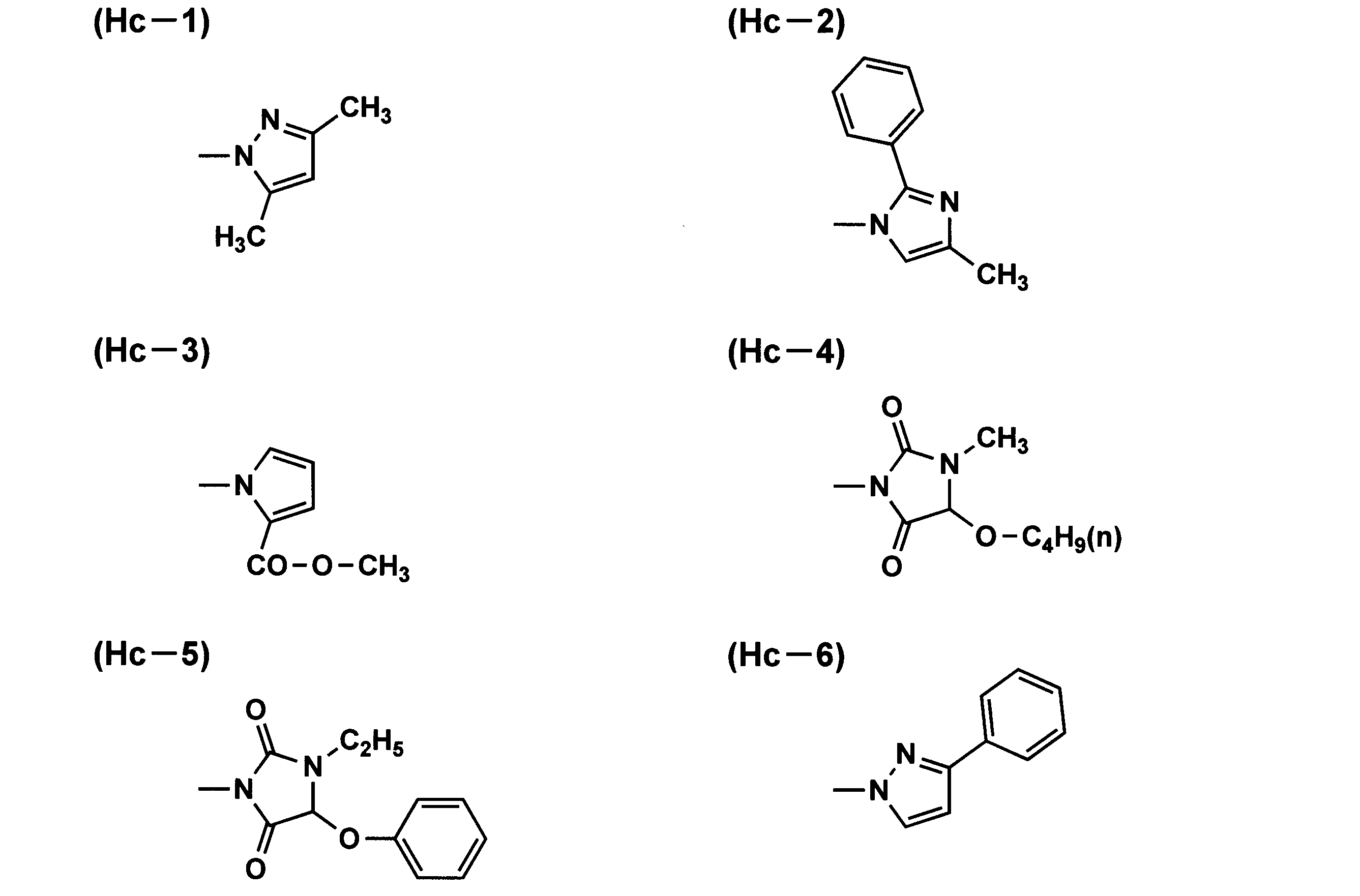

本発明に用いられる1,3,5-トリアジン環を有する化合物の具体例は、特開2006-113239号公報段落〔0143〕~〔0179〕を参照することができる。
本発明においては、二種類以上の1,3,5-トリアジン環を有する化合物を併用してもよい。二種類以上の円盤状化合物(例えば、1,3,5-トリアジン環を有する化合物とポルフィリン骨格を有する化合物)を併用してもよい。
本発明では、安息香酸フェニルエステル化合物の少なくとも一種をリターデーション調整剤として用いることが好ましく、中でも下記一般式(H)で示される安息香酸フェニルエステル化合物をセルロースエステルに添加することが好ましい。
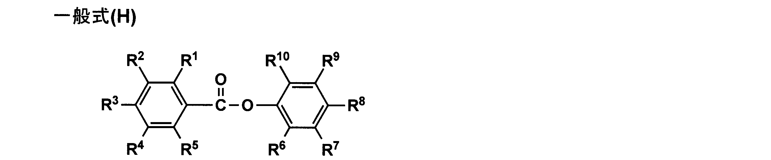
(式中、R1、R2、R3、R4、R5、R6、R7、R9及びR10は、それぞれ独立に、水素原子又は置換基を表し、R1、R2、R3、R4及びR5のうち少なくとも1つは電子供与性基を表す。R8は、水素原子、炭素数1~4のアルキル基、炭素数2~6のアルケニル基、炭素数2~6のアルキニル基、炭素数6~12のアリール基、炭素数1~12のアルコキシ基、炭素数6~12のアリールオキシ基、炭素数2~12のアルコキシカルボニル基、炭素数2~12のアシルアミノ基、シアノ基又はハロゲン原子を表す。)
一般式(H)の式中、R1、R2、R3、R4、R5、R6、R7、R9及びR10は、それぞれ独立に、水素原子、又は置換基を表し、置換基は後述の置換基Tが適用できる。
一般式(H)の式中、R1、R2、R3、R4、R5、R6、R7、R9及びR10は、それぞれ独立に、水素原子、又は置換基を表し、置換基は後述の置換基Tが適用できる。
R1、R2、R3、R4及びR5のうち少なくとも1つは電子供与性基を表す。好ましくはR1、R3又はR5のうちの1つが電子供与性基であり、R3が電子供与性基であることがより好ましい。
電子供与性基とは、Hammetのσp値がO以下のものを表し、Chem.Rev.,91,165(1991)記載のHammetのσp値がO以下のものが好ましく適用でき、より好ましくは、-0.85~0のものが用いられる。例えば、アルキル基、アルコキシ基、アミノ基、ヒドロキシ基(水酸基)などが挙げられる。
電子供与性基として好ましくは、アルキル基、アルコキシ基であり、より好ましくはアルコキシ基(好ましくは炭素数1~12、より好ましくは炭素数1~8、更に好ましくは炭素数1~6特に好ましくは炭素数1~4である)である。
R1として好ましくは、水素原子又は電子供与性基であり、より好ましくはアルキル基、アルコキシ基、アミノ基、ヒドロキシ基(水酸基)であり、更に好ましくは、炭素数1~4のアルキル基、炭素数1~12のアルコキシ基であり、特に好ましくはアルコキシ基(好ましくは炭素数1~12、より好ましくは炭素数1~8、更に好ましくは炭素数1~6、特に好ましくは炭素数1~4)であり、最も好ましくはメトキシ基である。
R2として好ましくは、水素原子、アルキル基、アルコキシ基、アミノ基、ヒドロキシ基(水酸基)であり、より好ましくは、水素原子、アルキル基、アルコキシ基であり、更に好ましくは水素原子、アルキル基(好ましくは炭素数1~4、より好ましくはメチル基である。)、アルコキシ基(好ましくは炭素数1~12、より好ましくは炭素数1~8、更に好ましくは炭素数1~6、特に好ましくは炭素数1~4)である。特に好ましくは水素原子、メチル基、メトキシ基である。
R3として好ましくは、水素原子又は電子供与性基であり、より好ましくは水素原子、アルキル基、アルコキシ基、アミノ基、ヒドロキシ基(水酸基)であり、更に好ましくは、アルキル基、アルコキシ基であり、特に好ましくはアルコキシ基(好ましくは炭素数1~12、より好ましくは炭素数1~8、更に好ましくは炭素数1~6、特に好ましくは炭素数1~4)である。最も好ましくはn-プロポキシ基、エトキシ基、メトキシ基である。
R4として好ましくは、水素原子又は電子供与性基であり、より好ましくは水素原子、アルキル基、アルコキシ基、アミノ基、ヒドロキシ基(水酸基)であり、更に好ましくは、水素原子、炭素数1~4のアルキル基、炭素数1~12のアルコキシ基(好ましくは炭素数1~12、より好ましくは炭素数1~8、更に好ましくは炭素数1~6、特に好ましくは炭素数1~4)であり、特に好ましくは水素原子、炭素数1~4のアルキル基、炭素数1~4のアルコキシ基であり、最も好ましくは水素原子、メチル基、メトキシ基である。
R5として好ましくは、水素原子、アルキル基、アルコキシ基、アミノ基、ヒドロキシ基(水酸基)であり、より好ましくは、水素原子、アルキル基、アルコキシ基であり、更に好ましくは水素原子、アルキル基(好ましくは炭素数1~4、より好ましくはメチル基)、アルコキシ基(好ましくは炭素数1~12、より好ましくは炭素数1~8、更に好ましくは炭素数1~6特に好ましくは炭素数1~4)である。特に好ましくは水素原子、メチル基、メトキシ基である。
R6、R7、R9及びR10として、好ましくは水素原子、炭素数1~12のアルキル基、炭素数1~12のアルコキシ基、ハロゲン原子であり、より好ましくは、水素原子、ハロゲン原子であり、更に好ましくは水素原子である。
R8は、水素原子、炭素数1~4のアルキル基、炭素数2~6のアルキニル基、炭素数6~12のアリール基、炭素数1~12のアルコキシ基、炭素数6~12のアリールオキシ基、炭素数2~12のアルコキシカルボニル基、炭素数2~12のアシルアミノ基、シアノ基又はハロゲン原子を表し、可能な場合には置換基を有してもよく、置換基としては後述の置換基Tが適用できる。また、置換基が更に置換してもよい。
R8として、好ましくは炭素数1~4のアルキル基、炭素数2~6のアルキニル基、炭素数6~12のアリール基、炭素数1~12のアルコキシ基、炭素数2~12のアルコキシカルボニル基、シアノ基であり、より好ましくは炭素数6~12のアリール基、炭素数1~12のアルコキシ基、炭素数2~12のアルコキシカルボニル基、シアノ基であり、更に好ましくは、炭素数1~6のアルコキシ基、炭素数6~12のアリール基、炭素数2~6のアルコキシカルボニル基、シアノ基であり、特に好ましくは、炭素数1~4のアルコキシ基、フェニル基、p-シアノフェニル基、p-メトキシフェニル基、炭素数2~4のアルコキシカルボニル基、シアノ基である。
一般式(H)で表される化合物のうち、より好ましい化合物は下記一般式(H-A)で表される化合物ある。

一般式(H-A)中、R1、R2、R4、R5、R6、R7、R8、R9及びR10は、それぞれ一般式(H)におけるそれらと同義であり、また好ましい範囲も同様である。
R11は、炭素数1~12のアルキル基を表す。R11で表されるアルキル基は直鎖でも分岐があってもよく、また更に置換基を有してもよいが、好ましくは炭素数1~12のアルキル基、より好ましくは炭素数1~8アルキル基、更に好ましくは炭素数1~6アルキル基、特に好ましくは炭素数1~4のアルキル基(例えば、メチル基、エチル基、n-プロピル基、iso-プロピル基、n-ブチル基、iso-ブチル基、tert-ブチル基などが挙げられる)を表す。
一般式(H)で表される化合物のうち、更に好ましい化合物は下記一般式(H-B)で表される化合物ある。

一般式(H-B)中、R1、R2、R4、R5、R6、R7、R9、R10は一般式(H)におけるそれらと同義であり、また好ましい範囲も同様である。
R11は、一般式(H-A)におけるそれと同義であり、また、好ましい範囲も同様である。
Xは、炭素数1~4のアルキル基、炭素数2~6のアルキニル基、炭素数6~12のアリール基、炭素数1~12のアルコキシ基、炭素数6~12のアリールオキシ基、炭素数2~12のアルコキシカルボニル基、炭素数2~12のアシルアミノ基、シアノ基又はハロゲン原子を表す。
R1、R2、R4、R5が全て水素原子の場合には、Xとして好ましくはアルキル基、アルキニル基、アリール基、アルコキシ基、アリールオキシ基であり、より好ましくは、アリール基、アルコキシ基、アリールオキシ基であり、更に好ましくはアルコキシ基(好ましくは炭素数1~12、より好ましくは炭素数1~8、更に好ましくは炭素数1~6、特に好ましくは炭素数1~4である。)であり、特に好ましくは、メトキシ基、エトキシ基、n-プロポキシ基、iso-プロポキシ基、n-ブトキシ基である。
R1、R2、R4、R5のうち少なくとも1つが置換基の場合には、Xとして好ましくはアルキニル基、アリール基、アルコキシカルボニル基、シアノ基、であり、より好ましくはアリール基(好ましくは炭素数6~12)、シアノ基、アルコキシカルボニル基(好ましくは炭素数2~12)であり、更に好ましくはアリール基(好ましくは炭素数6~12のアリール基であり、より好ましくはフェニル基、p-シアノフェニル基、p-メトキシフェニルである)、アルコキシカルボニル基(好ましくは炭素2~12、より好ましくは炭素数2~6、更に好ましくは炭素数2~4、特に好ましくはメトキシカルボニル、エトキシカルボニル、n-プロポキシカルボニルである)、シアノ基であり、特に好ましくは、フェニル基、メトキシカルボニル基、エトキシカルボニル基、n-プロポキシカルボニル基、シアノ基である。
一般式(H)で表される化合物のうち、更に好ましい化合物は下記一般式(H-C)で表される化合物ある。
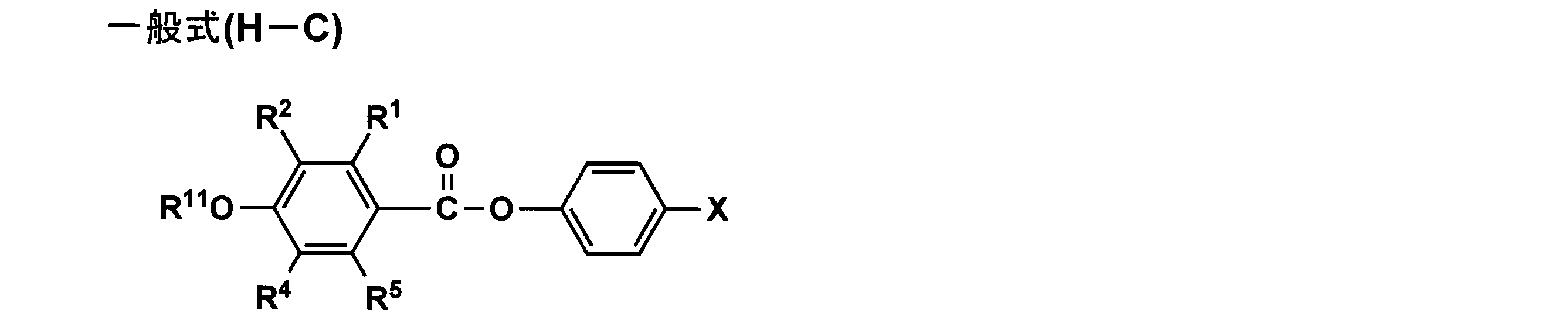
一般式(H-C)中、R1、R2、R4、R5、R11及びXは、一般式(H-B)におけるそれらと同義であり、また好ましい範囲も同様である。
一般式(H)で表される化合物の中で、特に好ましい化合物は下記一般式(H-D)で表される化合物である。

一般式(H-D)中、R2、R4及びR5は、一般式(H-C)におけるそれらと同義であり、また好ましい範囲も同様である。R21、R22は、それぞれ独立に、炭素数1~4のアルキル基を表す。X1は、炭素数6~12のアリール基、炭素数2~12のアルコキシカルボニル基、又はシアノ基を表す。
R21は、炭素数1~4のアルキル基を表し、好ましくは炭素数1~3のアルキル基であり、より好ましくはエチル基、メチル基である。
R22は、炭素数1~4のアルキル基を表し、好ましくは炭素数1~3のアルキル基であり、より好ましくはエチル基、メチル基であり、更に好ましくはメチル基である。
X1は、炭素数6~12のアリール基、炭素2~12アルコキシカルボニル基、又はシアノ基であり、好ましくは炭素数6~10のアリール基、炭素数2~6アルコキシカルボニル基、シアノ基であり、より好ましくはフェニル基、p-シアノフェニル基、p-メトキシフェニル基、メトキシカルボニル、エトキシカルボニル、n-プロポキシカルボニル、シアノ基であり、更に好ましくは、フェニル基、メトキシカルボニル基、エトキシカルボニル基、n-プロポキシカルボニル基、シアノ基である。
一般式(H)で表される化合物のうち、最も好ましい化合物は下記一般式(H-E)で表される化合物ある。
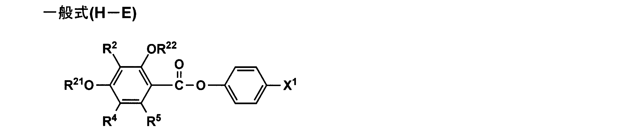
一般式(H-E)中、R2、R4及びR5は一般式(H-D)におけるそれらと同義であり、また好ましい範囲も同様である。ただし、いずれか1つは-OR13で表される基である。ここで、R13は炭素数1~4のアルキル基である。R21、R22、X1は一般式(H-D)におけるそれらと同義であり、また好ましい範囲も同様である。
好ましくは、R4及びR5の少なくともいずれかが-OR13で表される基であり、より好ましくはR4が-OR13で表される基であることである。
R13は炭素数1~4のアルキル基を表し、好ましくは炭素数1~3のアルキル基であり、より好ましくはエチル基、メチル基であり、更に好ましくはメチル基である。
以下に前述の置換基Tについて説明する。
置換基Tとしては例えばアルキル基(好ましくは炭素数1~20、より好ましくは炭素数1~12、特に好ましくは炭素数1~8であり、例えばメチル、エチル、iso-プロピル、tert-ブチル、n-オクチル、n-デシル、n-ヘキサデシル、シクロプロピル、シクロペンチル、シクロヘキシルなどが挙げられる。)、アルケニル基(好ましくは炭素数2~20、より好ましくは炭素数2~12、特に好ましくは炭素数2~8であり、例えばビニル、アリル、2-ブテニル、3-ペンテニルなどが挙げられる。)、アルキニル基(好ましくは炭素数2~20、より好ましくは炭素数2~12、特に好ましくは炭素数2~8であり、例えばプロパルギル、3-ペンチニルなどが挙げられる。)、アリール基(好ましくは炭素数6~30、より好ましくは炭素数6~20、特に好ましくは炭素数6~12であり、例えばフェニル、p-メチルフェニル、ナフチルなどが挙げられる。)、置換又は未置換のアミノ基(好ましくは炭素数0~20、より好ましくは炭素数0~10、特に好ましくは炭素数0~6であり、例えばアミノ、メチルアミノ、ジメチルアミノ、ジエチルアミノ、ジベンジルアミノなどが挙げられる。)、アルコキシ基(好ましくは炭素数1~20、より好ましくは炭素数1~12、特に好ましくは炭素数1~8であり、例えばメトキシ、エトキシ、ブトキシなどが挙げられる。)、アリールオキシ基(好ましくは炭素数6~20、より好ましくは炭素数6~16、特に好ましくは炭素数6~12であり、例えばフェニルオキシ、2-ナフチルオキシなどが挙げられる。)、アシル基(好ましくは炭素数1~20、より好ましくは炭素数1~16、特に好ましくは炭素数1~12であり、例えばアセチル、ベンゾイル、ホルミル、ピバロイルなどが挙げられる。)、アルコキシカルボニル基(好ましくは炭素数2~20、より好ましくは炭素数2~16、特に好ましくは炭素数2~12であり、例えばメトキシカルボニル、エトキシカルボニルなどが挙げられる。)、アリールオキシカルボニル基(好ましくは炭素数7~20、より好ましくは炭素数7~16、特に好ましくは炭素数7~10であり、例えばフェニルオキシカルボニルなどが挙げられる。)、アシルオキシ基(好ましくは炭素数2~20、より好ましくは炭素数2~16、特に好ましくは炭素数2~10であり、例えばアセトキシ、ベンゾイルオキシなどが挙げられる。)、アシルアミノ基(好ましくは炭素数2~20、より好ましくは炭素数2~16、特に好ましくは炭素数2~10であり、例えばアセチルアミノ、ベンゾイルアミノなどが挙げられる。)、アルコキシカルボニルアミノ基(好ましくは炭素数2~20、より好ましくは炭素数2~16、特に好ましくは炭素数2~12であり、例えばメトキシカルボニルアミノなどが挙げられる。)、アリールオキシカルボニルアミノ基(好ましくは炭素数7~20、より好ましくは炭素数7~16、特に好ましくは炭素数7~12であり、例えばフェニルオキシカルボニルアミノなどが挙げられる。)、スルホニルアミノ基(好ましくは炭素数1~20、より好ましくは炭素数1~16、特に好ましくは炭素数1~12であり、例えばメタンスルホニルアミノ、ベンゼンスルホニルアミノなどが挙げられる。)、スルファモイル基(好ましくは炭素数0~20、より好ましくは炭素数0~16、特に好ましくは炭素数0~12であり、例えばスルファモイル、メチルスルファモイル、ジメチルスルファモイル、フェニルスルファモイルなどが挙げられる。)、カルバモイル基(好ましくは炭素数1~20、より好ましくは炭素数1~16、特に好ましくは炭素数1~12であり、例えばカルバモイル、メチルカルバモイル、ジエチルカルバモイル、フェニルカルバモイルなどが挙げられる。)、アルキルチオ基(好ましくは炭素数1~20、より好ましくは炭素数1~16、特に好ましくは炭素数1~12であり、例えばメチルチオ、エチルチオなどが挙げられる。)、アリールチオ基(好ましくは炭素数6~20、より好ましくは炭素数6~16、特に好ましくは炭素数6~12であり、例えばフェニルチオなどが挙げられる。)、スルホニル基(好ましくは炭素数1~20、より好ましくは炭素数1~16、特に好ましくは炭素数1~12であり、例えばメシル、トシルなどが挙げられる。)、スルフィニル基(好ましくは炭素数1~20、より好ましくは炭素数1~16、特に好ましくは炭素数1~12であり、例えばメタンスルフィニル、ベンゼンスルフィニルなどが挙げられる。)、ウレイド基(好ましくは炭素数1~20、より好ましくは炭素数1~16、特に好ましくは炭素数1~12であり、例えばウレイド、メチルウレイド、フェニルウレイドなどが挙げられる。)、リン酸アミド基(好ましくは炭素数1~20、より好ましくは炭素数1~16、特に好ましくは炭素数1~12であり、例えばジエチルリン酸アミド、フェニルリン酸アミドなどが挙げられる。)、ヒドロキシ基、メルカプト基、ハロゲン原子(例えばフッ素原子、塩素原子、臭素原子、ヨウ素原子)、シアノ基、スルホ基、カルボキシ基、ニトロ基、ヒドロキサム酸基、スルフィノ基、ヒドラジノ基、イミノ基、ヘテロ環基(好ましくは炭素数1~30、より好ましくは1~12であり、ヘテロ原子としては、例えば窒素原子、酸素原子、硫黄原子、具体的には例えばイミダゾリル、ピリジル、キノリル、フリル、ピペリジル、モルホリノ、ベンゾオキサゾリル、ベンズイミダゾリル、ベンズチアゾリルなどが挙げられる。)、シリル基(好ましくは、炭素数3~40、より好ましくは炭素数3~30、特に好ましくは、炭素数3~24であり、例えば、トリメチルシリル、トリフェニルシリルなどが挙げられる)などが挙げられる。これらの置換基は更に置換されてもよい。
また、置換基が二つ以上ある場合は、同じでも異なってもよい。また、可能な場合には互いに連結して環を形成してもよい。
本発明に用いられる一般式(H)で表される化合物は、置換安息香酸とフェノール誘導体の一般的なエステル反応によって合成でき、エステル結合形成反応であればどのような反応を用いてもよい。例えば、置換安息香酸を酸ハロゲン化物に官能基変換した後、フェノールと縮合する方法、縮合剤あるいは触媒を用いて置換安息香酸とフェノール誘導体を脱水縮合する方法など挙げられる。
製造プロセス等を考慮すると置換安息香酸を酸ハロゲン化物に官能基変換した後、フェノールと縮合する方法が好ましい。
反応溶媒としては、炭化水素系溶媒(好ましくはトルエン、キシレンが挙げられる。)、エーテル系溶媒(好ましくはジメチルエーテル、テトラヒドロフラン、ジオキサンなどが挙げられる。)、ケトン系溶媒、エステル系溶媒、アセトニトリル、ジメチルホルムアミド、ジメチルアセトアミドなどを用いることができる。これらの溶媒は単独でも数種を混合して用いてもよく、反応溶媒として好ましくはトルエン、アセトニトリル、ジメチルホルムアミド、ジメチルアセトアミドである。
反応温度は、好ましくは0~150℃の範囲、より好ましくは0~100℃の範囲、更に好ましくは0~90℃の範囲であり、特に好ましくは20℃~90℃の範囲である。
本反応には塩基を用いないのが好ましく、塩基を用いる場合には有機塩基、無機塩基のどちらでもよく、好ましくは有機塩基であり、ピリジン、3級アルキルアミン(好ましくはトリエチルアミン、エチルジイソプルピルアミンなどが挙げられる)である。
本発明に用いられる安息香酸フェニルエステル化合物の具体例は、特開2006-154760号公報段落〔0183〕~〔0190〕を参照することができる。
更に、本発明に係るλ/4位相差フィルムは、溶液の紫外線吸収スペクトルの最大吸収波長(λmax)が250nmより短波長である棒状化合物をリターデーション調整剤として含有することが好ましい。
リターデーション調整剤の機能の観点では、棒状化合物は、少なくとも一つの芳香族環を有することが好ましく、少なくとも二つの芳香族環を有することが更に好ましい。棒状化合物は、直線的な分子構造を有することが好ましい。直線的な分子構造とは、熱力学的に最も安定な構造において棒状化合物の分子構造が直線的であることを意味する。熱力学的に最も安定な構造は、結晶構造解析又は分子軌道計算によって求めることができる。例えば、分子軌道計算ソフト(例、WinMOPAC2000、富士通(株)製)を用いて分子軌道計算を行い、化合物の生成熱が最も小さくなるような分子の構造を求めることができる。分子構造が直線的であるとは、上記のように計算して求められる熱力学的に最も安定な構造において、分子構造の角度が140度以上であることを意味する。棒状化合物は、液晶性を示すことが好ましい。棒状化合物は、加熱により液晶性を示す(サーモトロピック液晶性を有する)ことが更に好ましい。液晶相は、ネマティック相又はスメクティック相が好ましい。
棒状化合物としては、下記一般式(T)で表されるトランス-1,4-シクロヘキサンジカルボン酸エステル化合物が好ましい。
一般式(T):Ar1-L1-Ar2
一般式(T)において、Ar1及びAr2は、それぞれ独立に、芳香族基である。本明細書において、芳香族基は、アリール基(芳香族性炭化水素基)、置換アリール基、芳香族性ヘテロ環基及び置換芳香族性ヘテロ環基を含む。アリール基及び置換アリール基の方が、芳香族性ヘテロ環基及び置換芳香族性ヘテロ環基よりも好ましい。芳香族性ヘテロ環基のヘテロ環は、一般には不飽和である。芳香族性ヘテロ環は、5員環、6員環又は7員環であることが好ましく、5員環又は6員環であることが更に好ましい。芳香族性ヘテロ環は一般に最多の二重結合を有する。ヘテロ原子としては、窒素原子、酸素原子又は硫黄原子が好ましく、窒素原子又は硫黄原子が更に好ましい。芳香族性ヘテロ環の例には、フラン環、チオフェン環、ピロール環、オキサゾール環、イソオキサゾール環、チアゾール環、イソチアゾール環、イミダゾール環、ピラゾール環、フラザン環、トリアゾール環、ピラン環、ピリジン環、ピリダジン環、ピリミジン環、ピラジン環、及び1,3,5-トリアジン環が含まれる。芳香族基の芳香族環としては、ベンゼン環、フラン環、チオフェン環、ピロール環、オキサゾール環、チアゾール環、イミダゾール環、トリアゾール環、ピリジン環、ピリミジン環及びピラジン環が好ましく、ベンゼン環が特に好ましい。
一般式(T)において、Ar1及びAr2は、それぞれ独立に、芳香族基である。本明細書において、芳香族基は、アリール基(芳香族性炭化水素基)、置換アリール基、芳香族性ヘテロ環基及び置換芳香族性ヘテロ環基を含む。アリール基及び置換アリール基の方が、芳香族性ヘテロ環基及び置換芳香族性ヘテロ環基よりも好ましい。芳香族性ヘテロ環基のヘテロ環は、一般には不飽和である。芳香族性ヘテロ環は、5員環、6員環又は7員環であることが好ましく、5員環又は6員環であることが更に好ましい。芳香族性ヘテロ環は一般に最多の二重結合を有する。ヘテロ原子としては、窒素原子、酸素原子又は硫黄原子が好ましく、窒素原子又は硫黄原子が更に好ましい。芳香族性ヘテロ環の例には、フラン環、チオフェン環、ピロール環、オキサゾール環、イソオキサゾール環、チアゾール環、イソチアゾール環、イミダゾール環、ピラゾール環、フラザン環、トリアゾール環、ピラン環、ピリジン環、ピリダジン環、ピリミジン環、ピラジン環、及び1,3,5-トリアジン環が含まれる。芳香族基の芳香族環としては、ベンゼン環、フラン環、チオフェン環、ピロール環、オキサゾール環、チアゾール環、イミダゾール環、トリアゾール環、ピリジン環、ピリミジン環及びピラジン環が好ましく、ベンゼン環が特に好ましい。
置換アリール基及び置換芳香族性ヘテロ環基の置換基の例には、ハロゲン原子(F、Cl、Br、I)、ヒドロキシ、カルボキシ、シアノ、アミノ、アルキルアミノ基(例、メチルアミノ、エチルアミノ、ブチルアミノ、ジメチルアミノ)、ニトロ、スルホ、カルバモイル、アルキルカルバモイル基(例、N-メチルカルバモイル、N-エチルカルバモイル、N,N-ジメチルカルバモイル)、スルファモイル、アルキルスルファモイル基(例、N-メチルスルファモイル、N-エチルスルファモイル、N,N-ジメチルスルファモイル)、ウレイド、アルキルウレイド基(例、N-メチルウレイド、N,N-ジメチルウレイド、N,N,N′-トリメチルウレイド)、アルキル基(例、メチル、エチル、プロピル、ブチル、ペンチル、ヘプチル、オクチル、イソプロピル、s-ブチル、t-アミル、シクロヘキシル、シクロペンチル)、アルケニル基(例、ビニル、アリル、ヘキセニル)、アルキニル基(例、エチニル、ブチニル)、アシル基(例、ホルミル、アセチル、ブチリル、ヘキサノイル、ラウリル)、アシルオキシ基(例、アセトキシ、ブチリルオキシ、ヘキサノイルオキシ、ラウリルオキシ)、アルコキシ基(例、メトキシ、エトキシ、プロポキシ、ブトキシ、ペンチルオキシ、ヘプチルオキシ、オクチルオキシ)、アリールオキシ基(例、フェノキシ)、アルコキシカルボニル基(例、メトキシカルボニル、エトキシカルボニル、プロポキシカルボニル、ブトキシカルボニル、ペンチルオキシカルボニル、ヘプチルオキシカルボニル)、アリールオキシカルボニル基(例、フェノキシカルボニル)、アルコキシカルボニルアミノ基(例、ブトキシカルボニルアミノ、ヘキシルオキシカルボニルアミノ)、アルキルチオ基(例、メチルチオ、エチルチオ、プロピルチオ、ブチルチオ、ペンチルチオ、ヘプチルチオ、オクチルチオ)、アリールチオ基(例、フェニルチオ)、アルキルスルホニル基(例、メチルスルホニル、エチルスルホニル、プロピルスルホニル、ブチルスルホニル、ペンチルスルホニル、ヘプチルスルホニル、オクチルスルホニル)、アミド基(例、アセトアミド、ブチルアミド基、ヘキシルアミド、ラウリルアミド)及び非芳香族性複素環基(例、モルホリル、ピラジニル)が含まれる。
置換アリール基及び置換芳香族性ヘテロ環基の置換基としては、ハロゲン原子、シアノ、カルボキシ、ヒドロキシ、アミノ、アルキル置換アミノ基、アシル基、アシルオキシ基、アミド基、アルコキシカルボニル基、アルコキシ基、アルキルチオ基及びアルキル基が好ましい。アルキルアミノ基、アルコキシカルボニル基、アルコキシ基及びアルキルチオ基のアルキル部分とアルキル基とは、更に置換基を有していてもよい。アルキル部分及びアルキル基の置換基の例には、ハロゲン原子、ヒドロキシ、カルボキシ、シアノ、アミノ、アルキルアミノ基、ニトロ、スルホ、カルバモイル、アルキルカルバモイル基、スルファモイル、アルキルスルファモイル基、ウレイド、アルキルウレイド基、アルケニル基、アルキニル基、アシル基、アシルオキシ基、アルコキシ基、アリールオキシ基、アルコキシカルボニル基、アリールオキシカルボニル基、アルコキシカルボニルアミノ基、アルキルチオ基、アリールチオ基、アルキルスルホニル基、アミド基及び非芳香族性複素環基が含まれる。アルキル部分及びアルキル基の置換基としては、ハロゲン原子、ヒドロキシ、アミノ、アルキルアミノ基、アシル基、アシルオキシ基、アシルアミノ基、アルコキシカルボニル基及びアルコキシ基が好ましい。
一般式(T)において、L1は、アルキレン基、アルケニレン基、アルキニレン基、二価の飽和ヘテロ環基、-O-、-CO-及びそれらの組み合わせからなる群より選ばれる二価の連結基である。アルキレン基は、環状構造を有していてもよい。環状アルキレン基としては、シクロヘキシレンが好ましく、1,4-シクロヘキシレンが特に好ましい。鎖状アルキレン基としては、直鎖状アルキレン基の方が分岐を有するアルキレン基よりも好ましい。アルキレン基の炭素原子数は、1~20であることが好ましく、1~15であることがより好ましく、1~10であることが更に好ましく、1~8であることが更にまた好ましく、1~6であることが最も好ましい。
アルケニレン基及びアルキニレン基は、環状構造よりも鎖状構造を有することが好ましく、分岐を有する鎖状構造よりも直鎖状構造を有することが更に好ましい。アルケニレン基及びアルキニレン基の炭素原子数は、2~10であることが好ましく、2~8であることがより好ましく、2~6であることが更に好ましく、2~4であることが更にまた好ましく、2(ビニレン又はエチニレン)であることが最も好ましい。二価の飽和ヘテロ環基は、3員~9員のヘテロ環を有することが好ましい。ヘテロ環のヘテロ原子は、酸素原子、窒素原子、ホウ素原子、硫黄原子、ケイ素原子、リン原子又はゲルマニウム原子が好ましい。飽和ヘテロ環の例には、ピペリジン環、ピペラジン環、モルホリン環、ピロリジン環、イミダゾリジン環、テトラヒドロフラン環、テトラヒドロピラン環、1,3-ジオキサン環、1,4-ジオキサン環、テトラヒドロチオフェン環、1,3-チアゾリジン環、1,3-オキサゾリジン環、1,3-ジオキソラン環、1,3-ジチオラン環及び1,3,2-ジオキサボロランが含まれる。特に好ましい二価の飽和ヘテロ環基は、ピペラジン-1,4-ジイレン、1,3-ジオキサン-2,5-ジイレン及び1,3,2-ジオキサボロラン-2,5-ジイレンである。
組み合わせからなる二価の連結基の例を示す。
L-1:-O-CO-アルキレン基-CO-O-
L-2:-CO-O-アルキレン基-O-CO-
L-3:-O-CO-アルケニレン基-CO-O-
L-4:-CO-O-アルケニレン基-O-CO-
L-5:-O-CO-アルキニレン基-CO-O-
L-6:-CO-O-アルキニレン基-O-CO-
L-7:-O-CO-二価の飽和ヘテロ環基-CO-O-
L-8:-CO-O-二価の飽和ヘテロ環基-O-CO-
一般式(T)の分子構造において、L1を挟んで、Ar1とAr2とが形成する角度は、140度以上であることが好ましい。棒状化合物としては、下記一般式(U)で表される化合物が更に好ましい。
L-2:-CO-O-アルキレン基-O-CO-
L-3:-O-CO-アルケニレン基-CO-O-
L-4:-CO-O-アルケニレン基-O-CO-
L-5:-O-CO-アルキニレン基-CO-O-
L-6:-CO-O-アルキニレン基-O-CO-
L-7:-O-CO-二価の飽和ヘテロ環基-CO-O-
L-8:-CO-O-二価の飽和ヘテロ環基-O-CO-
一般式(T)の分子構造において、L1を挟んで、Ar1とAr2とが形成する角度は、140度以上であることが好ましい。棒状化合物としては、下記一般式(U)で表される化合物が更に好ましい。
一般式(U):Ar1-L2-X-L3-Ar2
一般式(U)において、Ar1及びAr2は、それぞれ独立に、芳香族基である。芳香族基の定義及び例は、一般式(T)のAr1及びAr2と同様である。
一般式(U)において、Ar1及びAr2は、それぞれ独立に、芳香族基である。芳香族基の定義及び例は、一般式(T)のAr1及びAr2と同様である。
一般式(U)において、L2及びL3は、それぞれ独立に、アルキレン基、-O-、-CO-及びそれらの組み合わせからなる群より選ばれる二価の連結基である。アルキレン基は、環状構造よりも鎖状構造を有することが好ましく、分岐を有する鎖状構造よりも直鎖状構造を有することが更に好ましい。アルキレン基の炭素原子数は、1~10であることが好ましく、1~8であることがより好ましく、1~6であることが更に好ましく、1~4であることが更にまた好ましく、1又は2(メチレン又はエチレン)であることが最も好ましい。L2及びL3は、-O-CO-又は-CO-O-であることが特に好ましい。
一般式(U)において、Xは、1,4-シクロヘキシレン、ビニレン又はエチニレンである。
棒状化合物は直線的な分子構造を有することが好ましい。そのため、トランス型の方がシス型よりも好ましい。具体例(2)及び(3)は、幾何異性体に加えて光学異性体(合計四種の異性体)を有する。幾何異性体については、同様にトランス型の方がシス型よりも好ましい。光学異性体については、特に優劣はなく、D、Lあるいはラセミ体のいずれでもよい。具体例(43)~(45)では、中心のビニレン結合にトランス型とシス型とがある。上記と同様の理由で、トランス型の方がシス型よりも好ましい。
本発明に用いられる棒状化合物の具体例は、特開2006-113239号公報段落〔0106〕~〔0112〕を参照できる。
溶液の紫外線吸収スペクトルにおいて最大吸収波長(λmax)が250nmより短波長である棒状化合物を、二種類以上併用してもよい。棒状化合物は、文献記載の方法を参照して合成できる。文献としては、Mol.Cryst.Liq.Cryst.,53巻、229頁(1979年)、同89巻、93頁(1982年)、同145巻、111頁(1987年)、同170巻、43頁(1989年)、J.Am.Chem.Soc.,113巻、1349頁(1991年)、同118巻、5346頁(1996年)、同92巻、1582頁(1970年)、J.Org.Chem.,40巻、420頁(1975年)、Tetrahedron、48巻16号、3437頁(1992年)を挙げることができる。
(マット剤)
本発明では、マット剤として微粒子をλ/4位相差フィルム中に含有させることができ、これによって、λ/4位相差フィルムが長尺フィルムの場合、搬送や巻き取りをしやすくすることができる。
本発明では、マット剤として微粒子をλ/4位相差フィルム中に含有させることができ、これによって、λ/4位相差フィルムが長尺フィルムの場合、搬送や巻き取りをしやすくすることができる。
マット剤の粒径は10nm~0.1μmの1次粒子若しくは2次粒子であるであることが好ましい。1次粒子の針状比は1.1以下の略球状のマット剤が好ましく用いられる。
微粒子としては、ケイ素を含むものが好ましく、特に二酸化珪素が好ましい。本発明に好ましい二酸化珪素の微粒子としては、例えば、日本アエロジル(株)製のアエロジルR972、R972V、R974、R812、200、200V、300、R202、OX50、TT600(以上日本アエロジル(株)製)の商品名で市販されているものを挙げることができ、アエロジル200V、R972、R972V、R974、R202、R812を好ましく用いることができる。ポリマーの微粒子の例として、シリコーン樹脂、弗素樹脂及びアクリル樹脂を挙げることができる。シリコーン樹脂が好ましく、特に三次元の網状構造を有するものが好ましく、例えば、トスパール103、同105、同108、同120、同145、同3120及び同240(東芝シリコーン(株)製)を挙げることができる。
二酸化珪素の微粒子は、1次平均粒子径が20nm以下であり、かつ見かけ比重が70g/L以上であるものが好ましい。1次粒子の平均径が5~16nmがより好ましく、5~12nmが更に好ましい。1次粒子の平均径が小さい方がヘイズが低く好ましい。見かけ比重は90~200g/L以上が好ましく、100~200g/L以上がより好ましい。見かけ比重が大きい程、高濃度の微粒子分散液を作ることが可能になり、ヘイズ、凝集物が発生せず好ましい。
本発明におけるマット剤の添加量は、λ/4位相差フィルム1m2当たり0.01~1.0gが好ましく、0.03~0.3gがより好ましく、0.08~0.16gが更に好ましい。
(その他の添加剤)
この他、カオリン、タルク、ケイソウ土、石英、炭酸カルシウム、硫酸バリウム、酸化チタン、アルミナ等の無機微粒子、カルシウム、マグネシウム等のアルカリ土類金属の塩等の熱安定剤を加えてもよい。更に界面活性剤、剥離促進剤、帯電防止剤、難燃剤、滑剤、油剤等も加えてもよい。
この他、カオリン、タルク、ケイソウ土、石英、炭酸カルシウム、硫酸バリウム、酸化チタン、アルミナ等の無機微粒子、カルシウム、マグネシウム等のアルカリ土類金属の塩等の熱安定剤を加えてもよい。更に界面活性剤、剥離促進剤、帯電防止剤、難燃剤、滑剤、油剤等も加えてもよい。
<長尺フィルム原反の製造方法>
長尺延伸フィルムを作製するために用いられる長尺フィルム原反は、公知の方法、例えば、溶液キャスト成形法、押出成形法、インフレーション成形法などによって得ることができる。これらのうち溶液キャスト成形法はフィルムの平面性、透明度に優れ、押出成形法は斜め延伸後の厚さ方向のリターデーションRtを小さくすることが容易となり、残留揮発性成分量が少なくフィルムの寸法安定性にも優れるので好ましい。この長尺フィルム原反は、単層若しくは2層以上の積層フィルムであってもよい。積層フィルムは共押出成形法、共流延成形法、フィルムラミネイション法、塗布法などの公知の方法で得ることができる。これらのうち共押出成形法、共流延成形法が好ましい。
長尺延伸フィルムを作製するために用いられる長尺フィルム原反は、公知の方法、例えば、溶液キャスト成形法、押出成形法、インフレーション成形法などによって得ることができる。これらのうち溶液キャスト成形法はフィルムの平面性、透明度に優れ、押出成形法は斜め延伸後の厚さ方向のリターデーションRtを小さくすることが容易となり、残留揮発性成分量が少なくフィルムの寸法安定性にも優れるので好ましい。この長尺フィルム原反は、単層若しくは2層以上の積層フィルムであってもよい。積層フィルムは共押出成形法、共流延成形法、フィルムラミネイション法、塗布法などの公知の方法で得ることができる。これらのうち共押出成形法、共流延成形法が好ましい。
本発明では、延伸に供給される長尺フィルム原反の流れ方向の厚さムラσmは、後述する斜め延伸テンター入口でのフィルムの引取張力を一定に保ち、配向角やリターデーションといった光学特性を安定させる観点から、0.30μm未満、好ましくは0.25μm未満、さらに好ましくは0.20μm未満であることが好ましい。長尺フィルム原反の流れ方向の厚さムラσmが0.30μm以上となると長尺延伸フィルムのリターデーションや配向角といった光学特性のバラツキが顕著に悪化する。
長尺フィルム原反の流れ方向の厚さムラσmを上記範囲とするためには、押出成形法の場合は、特開2004-233604号公報に記載されているような、冷却ドラムに密着させる時の溶融状態の熱可塑性樹脂を安定な状態に保つ方法により達成可能である。具体的には、1)溶融押出法で長尺フィルム原反を製造する際に、ダイスから押し出されたシート状の熱可塑性樹脂を50kPa以下の圧力下で冷却ドラムに密着させて引き取る方法;2)溶融押出法で長尺フィルム原反を製造する際に、ダイス開口部から最初に密着する冷却ドラムまでを囲い部材で覆い、囲い部材からダイス開口部又は最初に密着する冷却ドラムまでの距離を100mm以下とする方法;3)溶融押出法で長尺フィルム原反を製造する際に、ダイス開口部から押し出されたシート状の熱可塑性樹脂より10mm以内の雰囲気の温度を特定の温度に加温する方法;4)関係を満たすようにダイスから押し出されたシート状の熱可塑性樹脂を50kPa以下の圧力下で冷却ドラムに密着させて引き取る方法;5)溶融押出法で長尺フィルム原反を製造する際に、ダイス開口部から押し出されたシート状の熱可塑性樹脂に、最初に密着する冷却ドラムの引取速度との速度差が0.2m/s以下の風を吹き付ける方法;が挙げられる。
また、長尺フィルム原反として、幅方向の厚さ勾配を有するフィルムが供給されてもよい。延伸が完了した位置におけるフィルム厚さを最も均一なものとしうるような長尺フィルム原反の厚さの勾配は、実験的に厚さ勾配を様々に変化させたフィルムを延伸することにより、経験的に求めることができる。長尺フィルム原反の厚さの勾配は、例えば、厚さの厚い側の端部の厚さが、厚さの薄い側の端部よりも0.5~3%程度厚くなるように調整することができる。
長尺フィルム原反の幅は、特に限定されないが、500~4000mmの範囲、好ましくは1000~3000mmの範囲とすることができる。また、長尺フィルム原反の総膜厚は、特に限定されないが、20~400μmの範囲、好ましくは20~200μmの範囲内であることが好ましい。
また、上記長尺フィルム原反の幅調整方法として、溶液キャスト成形法、押出成形法にて得られたフィルムを幅手方向に横延伸、若しくは搬送方向に縦延伸をしてもよい。
斜め延伸時の延伸温度での好ましい弾性率は、ヤング率で表して、0.01MPa以上5000MPa以下、更に好ましくは0.1MPa以上500MPa以下である。弾性率が低すぎると、延伸時・延伸後の収縮率が低くなり、シワが消えにくくなり、また高すぎると、延伸時にかかる張力が大きくなり、フィルムの両側縁部を保持する部分の強度を高くする必要が生じ、後工程のテンターに対する負荷が大きくなる。
<斜め延伸テンターによる延伸>
本実施形態に係る製造方法における延伸に供される長尺の長尺フィルム原反に斜め方向の配向を付与するために、斜め延伸テンターを用いる。本実施形態で用いられる斜め延伸テンターは、レールパターンやフィルム把持具の搬送速度を多様に変化させることにより、フィルムの配向角を自在に設定でき、さらに、フィルムの配向軸をフィルム幅方向に渡って左右均等に高精度に配向させることができ、かつ、高精度でフィルム厚さやリターデーションを制御できるフィルム延伸装置であることが好ましい。
本実施形態に係る製造方法における延伸に供される長尺の長尺フィルム原反に斜め方向の配向を付与するために、斜め延伸テンターを用いる。本実施形態で用いられる斜め延伸テンターは、レールパターンやフィルム把持具の搬送速度を多様に変化させることにより、フィルムの配向角を自在に設定でき、さらに、フィルムの配向軸をフィルム幅方向に渡って左右均等に高精度に配向させることができ、かつ、高精度でフィルム厚さやリターデーションを制御できるフィルム延伸装置であることが好ましい。
図2のA、Bは本実施形態に係る長尺延伸フィルムの製造方法に用いられる斜め延伸可能なテンターの模式図である。ただし、これは一例であって本発明はこれに限定されるものではない。
テンター入り口側のガイドローラ12-1によって方向を制御された長尺フィルム原反4は、外側のフィルム保持開始点8-1、内側のフィルム保持開始点8-2の位置で把持具(クリップつかみ部ともいう)によって把持される。
左右一対のフィルム把持具は互いに等速度で、斜め延伸テンター6にて外側のフィルム把持手段の軌跡7-1、内側のフィルム把持手段の軌跡7-2で示される斜め方向に搬送、延伸され、外側のフィルム把持終了点9-1、内側のフィルム把持終了点9-2によって把持を解放され、テンター出口側のガイドローラ12-2によって搬送を制御されて斜め延伸フィルム5が形成される。図中、長尺フィルム原反は、フィルムの送り方向14-1に対して、フィルムの延伸方向14-2の角度(繰出し角度θi)で斜め延伸される。
図2A、Bにおいて、把持具の走行速度は適宜選択できるが、通常、1~100m/分の範囲である。
また、左右一対のフィルム把持具が互いに等速度とは実質的に、左右一対の把持具の走行速度の差として走行速度の1%以下であることを意味する。
一般的なテンター装置等では、チェーンを駆動するスプロケットの歯の周期、駆動モーターの周波数等に応じ、秒以下のオーダーで発生する速度ムラがあり、しばしば数%のムラを生ずるが、これらは本発明の実施形態で述べる速度差には該当しない。
図2Cは本実施形態に係る長尺延伸フィルムの製造方法に用いられる斜め延伸可能なテンターの模式図である。ただし、これは一例であって本発明はこれに限定されるものではない。
テンター入口部においてフィルムの両端を把持した左右一対の把持具は、テンター内初期において左右のレール間の距離が一定のゾーンでは左右のレール上を等速で走行し、その後左右のレール間距離が拡幅するゾーンにおいては左右のレール上を異なる速度で走行し、その後再び左右のレール間距離が等しくなるゾーンにおいて左右のレール上を等速で走行するようになる。
例えば、図2C中の左側のレールを走行する把持具が図中右側のレールを走行する把持具よりも速い場合を例にあげて説明する。
テンター入り口側のガイドローラ12-1によって方向を制御された長尺フィルム原反4は、外側のフィルム把持開始点8-1、内側のフィルム把持開始点8-2の位置で把持具によって把持される。その後左右のレール間隔が等しい領域においては左右一対の把持具はレール上を等速で走行する。その後左右のレールが拡幅を始める点10-1及び10-2において、図中左側の把持具(以下、高速側の把持具)の走行速度が図中右側の把持具(以下、低速側の把持具)の走行速度よりも速く走行しはじめ、左右のレールが拡幅を終えて左右のレールの拡幅が終了する点11-3において、高速側の把持具は再度低速側の把持具と等しい走行速度まで減速し、左右一対の把持具は再び同じ速度で走行を始める。
その後、低速側の把持具が、左右レールの拡幅が終了する点11-1まで到達した際に、左右一対の把持具の片方は11-2に到達することになる。
この後、左右一対のクリップは等速に左右レール上を走行し、左側把持終了点9-2において左側の把持具がフィルムを解放し、次いで右側把持終了点9-1において右側の把持具がフィルムを解放し、斜め延伸が終了する。
図2Dは本実施形態に係る長尺延伸フィルムの製造方法に用いられる斜め延伸可能なテンターの模式図である。ただし、これは一例であって本発明はこれに限定されるものではない。
テンター入口部においてフィルムの両端を把持した左右一対の把持具は、テンター内初期において左右のレール間の距離が一定のゾーンでは左右のレール上を異なる速度で走行する。図2Dで示されるテンターは、左右のレール間距離が拡幅する箇所を有するテンターである。テンター入口部8-1、8-2にて左右一対の把持具がフィルムを把持し、左右の把持具はそれぞれ異なる速度で左右のレール上を走行する。左右一対の把持具のうち高速側の把持具がテンター出口部の把持解放点9-2に到達した際に、対となる低速側のクリップは11-1に位置することになるため、左右一対の把持具によって把持されたフィルムは斜め延伸されることになる。
図2Dで示されるテンターは、左右のレール間距離が拡幅する箇所を有するテンターであるが、必ずしも左右のレール間距離が拡幅する箇所を有していなくてもよい。
図2C及びDにおいて、把持具の走行速度は適宜選択できるが、通常、1~100m/分の範囲である。
また、左右一対のフィルム把持具がそれぞれ異なる速度で走行するとは実質的に、左右一対の把持具の走行速度の差として、走行速度の1%を超えることを意味する。
左右一対の把持具の走行速度の差としては、走行速度の1%を超えて50%以下が好ましく、走行速度の1%を超えて30%以下がさらに好ましく、走行速度の1%を超えて10%以下がさらに好ましい。
また、図2Cにおいては、テンターの途中にて把持具の走行速度が変わる機構を有しているテンターであれば公知のものを用いることができる。
一般的なテンター装置等では、チェーンを駆動するスプロケットの歯の周期、駆動モーターの周波数等に応じ、秒以下のオーダーで発生する速度ムラがあり、しばしば数%のムラを生ずるが、これらは本発明の実施形態で述べる速度差には該当しない。
本発明の実施形態に係る長尺延伸フィルムの製造方法は、上記斜め延伸可能なテンターを用いて行う。このテンターは、長尺フィルム原反を、オーブンによる加熱環境下で、その進行方向(フィルム幅方向の中点の移動方向)に対して斜め方向に拡幅する装置である。このテンターは、オーブンと、フィルムを搬送するための把持具が走行する左右で一対のレールと、該レール上を走行する多数の把持具とを備えている。フィルムロールから繰り出され、テンターの入口部に順次供給されるフィルムの両端を、把持具で把持し、オーブン内にフィルムを導き、テンターの出口部で把持具からフィルムを開放する。把持具から開放されたフィルムは巻芯に巻き取られる。一対のレールは、それぞれ無端状の連続軌道を有し、テンターの出口部でフィルムの把持を開放した把持具は、外側を走行して順次入口部に戻されるようになっている。
なお、図2A~Dで代表されるように、テンターのレール形状は、製造すべき長尺延伸フィルムに与える配向角θ、延伸倍率等に応じて、左右で非対称若しくは左右対称な形状となっており、手動で又は自動で微調整できるようになっている。本発明においては、長尺の熱可塑性樹脂フィルムを延伸し、配向角θが延伸後の巻取り方向に対して、好ましくは10~80°の範囲内で任意の角度に設定できるようになっている。
また、左右の把持具の走行速度差については、テンターの延伸方式により適宜選択される。
また、本発明の実施形態に係る製造方法で用いられる斜め延伸テンターでは、各レール部及びレール連結部の位置を自由に設定できることが好ましい。したがって、斜め延伸店ターは、任意の入り口幅及び出口幅を設定すると、これに応じた延伸倍率にすることができる(下記、図2の○部は連結部の一例である。)。
本発明の実施形態に係る製造方法で用いられる斜め延伸テンターにおいて、特に図2A、Bのようにテンター内部において、把持具の軌跡を規制するレールには、しばしば大きい屈曲率が求められる。急激な屈曲による把持具同士の干渉、あるいは局所的な応力集中を避ける目的から、屈曲部では把持具の軌跡が円弧を描くようにすることが望ましい。
図2Aで示される斜め延伸テンターにおいては、長尺フィルム原反のテンター入口での進行方向14-1は、延伸後のフィルムのテンター出側での進行方向14-2と異なっている。繰出し角度θiは、テンター入口での進行方向14-1と延伸後のフィルムのテンター出側での進行方向14-2とのなす角度である。
図2Bで示される斜め延伸テンターにおいては、長尺フィルム原反のテンター入口での進行方向14-1は、テンター内で繰出し角度θiにてテンター入口での進行方向とは異なる方向に転換され搬送される。その後さらに搬送方向が転換され、最終的には延伸後のフィルムのテンター出側での進行方向一致するような軌跡をとる。
本発明においては、上述のように好ましくは10~80°の配向角θを持つフィルムを製造するため、繰出し角度θiは、10°<θi<60°、好ましくは15°<θi<50°で設定される。繰出し角度θiを前記範囲とすることにより、得られるフィルムの幅方向の光学特性のバラツキが良好となる(小さくなる)。
図2A、Bで示されるような本発明の実施形態において、テンターの左右の把持具は、前後の把持具と一定間隔を保って、一定速度で走行するようになっている。
図2C、Dで示される斜め延伸テンターにおいては長尺フィルム原反のテンター入口での進行方向と、テンター内よりフィルムを繰り出す角度は一致している。
図2C、Dで示されるような本発明の実施形態において、テンターの左右の把持具は、それぞれ異なる速度で走行するようになっている。
図3AからDは、本発明の図2AからDで示される斜め延伸テンターにおける延伸方向について模式図で示している。
図3A、Bにおいては、図中に示されるように、搬送フィルムの両端が初めて把持具によって把持される点、つまり把持開始点A1とA1から導入側の搬送フィルムの中心線に略垂直に引いた直線が、反対側の把持手段の軌跡と交わる点B1(つまり反対側のフィルム把持開始点)の2点を起点とし、両端の把持具を実質的に一定速度で搬送すると、単位時間ごとにA1からA2,A3と経て延伸終了点Anに移動し、B1は同様にB1からB2,B3と経て延伸終了点Bnに移動する。このような延伸方法を用いることで、図3A、Bで示されるように把持部AnはBnに対して次第に遅れていくため、延伸方向は、幅方向から徐々に傾斜していく。本発明の実質的な把持終了点(把持された搬送フィルムが把持していた把持具より解放される点)は、搬送フィルムの両端又はどちらか一方の端部が把持具から解放される点、つまり把持終了点Bxと、Bxから次工程へ送られる搬送フィルムの中心線に略垂直に引いた直線が、反対側の把持手段の軌跡と交わる点Ayの2点で定義される。
最終的なフィルムの延伸方向の角度は把持終了点の距離W(BxとAyの距離)とAxとAyの比率で決まる。
従って、延伸方向が次方向への搬送方向に対しなす傾斜角θfは、
tanθf=W/(Ay-Ax)
即ち、
tanθf=W/|LA-LB|
を満たす角度となる。ここで略垂直とは90±1°以内にあることを意味する。
tanθf=W/(Ay-Ax)
即ち、
tanθf=W/|LA-LB|
を満たす角度となる。ここで略垂直とは90±1°以内にあることを意味する。
ここでLAとは大回り側のテンターレール上を把持具が把持開始点から把持終了点までの走行距離であり、LBとは小回り側のテンターレール軌跡上を把持具が把持開始点から把持終了点まで動いた距離であり、|LA-LB|は把持終了点における、左右一対の把持具がテンターレール上を走行した距離の差である。
図3C、Dにおいては、図中に示されるように、搬送フィルムの両端が初めて把持具によって把持される点、つまり把持開始点C1とC1から導入側の搬送フィルムの中心線に略垂直に引いた直線が、反対側の把持手段の軌跡と交わる点D1(つまり反対側のフィルム把持開始点)の2点を起点とし、両端の把持具をそれぞれ異なる速度、例えば把持具Cの走行速度が把持具Dの走行速度よりも速い速度で搬送すると、単位時間ごとにC1からC2,C3と経て延伸終了点Cn移動し、D1は同様にD1からD2,D3と経て延伸終了点Dnに移動する。このような延伸方法を用いることで、図3C、Dで示されるように把持部DnはCnに対して次第に遅れていくため、延伸方向は、幅方向から徐々に傾斜していく。本発明の実質的な把持終了点(把持された搬送フィルムが把持していた把持具より解放される点)は、高速側の把持具が把持する搬送フィルムの端部が把持具から解放される点、つまり把持終了点Cxと、Cxから次工程へ送られる搬送フィルムの中心線に略垂直に引いた直線が、反対側の把持手段の軌跡と交わる点Dyの2点で定義される。
最終的なフィルムの延伸方向の角度は把持終了点の距離W(CxとDyの距離)とDxとDyの比率で決まる。
従って、延伸方向が次方向への搬送方向に対しなす傾斜角θfは、
tanθf=W/(Dy-Dx)
即ち、
tanθf=W/|LC-LD|
を満たす角度となる。ここで略垂直とは90±1°以内にあることを意味する。
tanθf=W/(Dy-Dx)
即ち、
tanθf=W/|LC-LD|
を満たす角度となる。ここで略垂直とは90±1°以内にあることを意味する。
ここでLCとは高速側のテンターレール上を把持具が把持開始点から把持終了点までの走行距離であり、LDとは低速側のテンターレール軌跡上を把持具が把持開始点から把持終了点まで動いた距離であり、|LC-LD|は把持終了点における、左右一対の把持具がテンターレール上を走行した距離の差である。
また、図3を用いて本発明における延伸倍率の定義について説明する。
斜め延伸テンターにおいて搬送フィルムが把持具によって初めて把持される把持開始点A1からB1間までの直線距離をLo,前記把持具の両方が斜め延伸テンター内の全ての延伸ゾーンを通過した際の把持具の位置(延伸終了点)をAn(若しくはDn)、Bn(若しくはCn)としたときのAnからBn間(若しくはDnからCn間)の直線距離をLとおいたときの斜め延伸テンター内における延伸倍率Rは、
R=L/L0
で定義される。
R=L/L0
で定義される。
このときの延伸倍率Rは、好ましくは1.3~3.0の範囲、より好ましくは1.5~2.5の範囲である。延伸倍率がこの範囲にあると幅方向厚さムラが小さくなるので好ましい。斜め延伸テンターの延伸ゾーンにおいて、幅方向で延伸温度に差を付けると幅方向厚さムラをさらに良好なレベルにすることが可能になる。
斜め延伸テンター内を走行するフィルムは、フィルムが走行するレールパターンに応じて、テンター内に予熱ゾーン、横延伸ゾーン、斜め延伸ゾーン、保持ゾーン、冷却ゾーン等に区分けされたオーブンを通過する。ただし、必ずしも上記ゾーンの全てを上記順序でフィルムを搬送させる必要はなく、例えば下記組み合わせ例のように、上記ゾーンの一部のみを使用したり、上記ゾーンのうち任意のゾーンを数回使用したりしてもよい。
予熱ゾーン/斜め延伸ゾーン/保持ゾーン/冷却ゾーン
予熱ゾーン/横延伸ゾーン/斜め延伸ゾーン/保持ゾーン/冷却ゾーン
予熱ゾーン/斜め延伸ゾーン/横延伸ゾーン/保持ゾーン/冷却ゾーン
予熱ゾーン/横延伸ゾーン1/斜め延伸ゾーン/横延伸ゾーン2/保持ゾーン/冷却ゾーン
予熱ゾーン/横延伸ゾーン1/斜め延伸ゾーン1/横延伸ゾーン2/斜め延伸ゾーン2/保持ゾーン/冷却ゾーン
予熱ゾーンとは、オーブン入口部において、フィルムの両端を把持した把持具の間隔が一定の間隔を保ったまま走行する区間をさす。
予熱ゾーン/横延伸ゾーン/斜め延伸ゾーン/保持ゾーン/冷却ゾーン
予熱ゾーン/斜め延伸ゾーン/横延伸ゾーン/保持ゾーン/冷却ゾーン
予熱ゾーン/横延伸ゾーン1/斜め延伸ゾーン/横延伸ゾーン2/保持ゾーン/冷却ゾーン
予熱ゾーン/横延伸ゾーン1/斜め延伸ゾーン1/横延伸ゾーン2/斜め延伸ゾーン2/保持ゾーン/冷却ゾーン
予熱ゾーンとは、オーブン入口部において、フィルムの両端を把持した把持具の間隔が一定の間隔を保ったまま走行する区間をさす。
横延伸ゾーンとは、フィルムの両端を把持した把持具の間隔が開きだし、所定の間隔になるまでの区間をさす。このとき、両端の把持具が走行するレールの開き角度は、両レールともに同じ角度で開いてもよいし、各々異なる角度で開いてもよい。
斜め延伸ゾーンとは、フィルムの両端を把持した把持具が、把持具間隔を一定に保ったままあるいは広がりながら、屈曲するレール上を走行しはじめてから両把持具がともに再度直線レール上を走行しはじめるまでの区間をさす。
保持ゾーンとは、横延伸ゾーンあるいは斜め延伸ゾーンより後の把持具の間隔が再び一定となる期間において、両端の把持具が互いに平行を保ったまま走行する区間をさす。
冷却ゾーンとは、保持ゾーンより後の区間において、ゾーン内の温度がフィルムを構成する熱可塑性樹脂のガラス転移温度Tg℃以下に設定される区間をさす。
このとき、冷却によるフィルムの縮みを考慮して、あらかじめ対向する把持具間隔を狭めるようなレールパターンとしてもよい。
各ゾーンの温度は、熱可塑性樹脂のガラス転移温度Tgに対し、予熱ゾーンの温度はTg~Tg+30℃の範囲、延伸ゾーンの温度はTg~Tg+30℃の範囲、冷却ゾーンの温度はTg-30~Tg℃の範囲に設定することが好ましい。
なお、幅方向の厚さムラの制御のために延伸ゾーンにおいて幅方向に温度差を付けてもよい。延伸ゾーンにおいて幅方向に温度差をつけるには、温風を恒温室内に送り込むノズルの開度を幅方向で差を付けるように調整する方法や、ヒーターを幅方向に並べて加熱制御するなどの公知の手法を用いることができる。
さらに、前記長尺延伸フィルムのシワ、寄りの発生を解決するために、延伸時にフィルムの支持性を保ち、揮発分率が5体積%以上の状態を存在させて延伸した後、収縮させながら揮発分率を低下させることも好ましい。フィルムの支持性を保つとは、フィルムの膜性を損なうことなく両側縁を把持することを意味する。揮発分率については、延伸操作工程において常に5体積%以上の状態を維持していてもよいし、延伸操作工程の一部の区間に限って揮発分率が5体積%以上の状態を維持してもよい。後者の場合、入り口位置を起算点として全延伸区間の50%以上の区間、揮発分率が12体積%以上の状態となっていることが好ましい。いずれにせよ、延伸前に揮発分率が12体積%以上の状態を存在させておくことが好ましい。ここで、揮発分率(単位;体積%)とは、フィルムの単位体積あたりに含まれる揮発成分の体積を表し、揮発成分体積をフィルム体積で除した値とする。
テンターの入口に最も近いガイドローラは、フィルムの走行を案内する従動ローラであり、不図示の軸受部を介してそれぞれ回転自在に軸支されている。ローラの材質は、公知のものを用いることが可能であるが、フィルムの傷つきを防止するためにセラミックコートを施したり、アルミニウム等の軽金属にクロームメッキを施す等、軽量化を図るのが好適である。このローラは、フィルムの走行時の軌道を安定させるために設けられるものである。
また、このローラの上流側のローラのうちの1本は、ゴムローラを圧接させてニップすることが好ましい。このようなニップローラにすることで、フィルムの流れ方向における繰出張力の変動を抑えることが可能だからである。
テンターの入口に最も近いガイドローラの両端(左右)の一対の軸受部には、当該ローラにおいてフィルムに生じている張力を検出するための第1張力検出装置、第2フィルム張力検出装置がそれぞれ設けられている。フィルム張力検出装置としては、例えばロードセルを用いることができる。ロードセルとしては、引張又は圧縮型の公知のものを用いることができる。ロードセルは、着力点に作用する荷重を起歪体に取り付けられた歪ゲージにより電気信号に変換して検出する装置である。
ロードセルは斜め延伸テンターの入口に最も近いガイドローラの左右の軸受部に設置されることにより、走行中のフィルムがローラに及ぼす力、即ちフィルムの両側縁近傍に生じているフィルム進行方向における張力を左右独立に検出するものである。なお、ローラの軸受部を構成する支持体に歪ゲージを直接取り付けて、該支持体に生じる歪に基づいて荷重、即ちフィルム張力を検出するようにしてもよい。発生する歪とフィルム張力との関係は、あらかじめ計測され、既知であるものとする。
上述したようなフィルム張力検出装置を設けて、斜め延伸テンターの入口に最も近いガイドローラにおけるフィルムの両側縁近傍の張力を検出するようにしたのは、フィルムの位置及び方向が、フィルム延伸装置の入口部の位置及び方向に対してズレが生じている場合、このズレ量に応じて、斜め延伸テンターの入口に最も近いガイドローラにおけるフィルムの両側縁近傍の張力に差を生じることになるため、この張力差を検出することによって、当該ズレの程度を判別するためである。フィルムの位置及び方向が、フィルム延伸装置の入口部の位置及び方向との関係で適正であれば、ローラに作用する荷重は左右で粗均等になり、互いの位置がズレていれば左右のフィルム張力に差が生じるのである。
従って、斜め延伸テンターの入口に最も近いガイドローラにおける左右のフィルム張力差が等しくなるように、フィルムの位置及び角度を、適切に調整すれば、フィルム延伸装置の入口部における把持具による把持が安定し、把持具外れ等の障害の発生を少なくできる。更に、フィルム延伸装置による斜め延伸後のフィルムの幅方向における物性を安定させることができる。
配向角の微調整や製品バリエーションに対応するために斜め延伸テンター入口でのフィルム進行方向と斜め延伸テンター出口でのフィルム進行方向とがなす角度の調整が必要となる。その際、製膜及び斜め延伸を連続して行うことが、生産性や収率の点で好ましい。製膜工程、斜め延伸工程、巻取工程を連続して行う場合、製膜工程と巻取工程でのフィルムの進行方向が一致していることが、工程の幅を小さくできる点で好ましい。そのような工程とするには、製膜したフィルムを斜め延伸テンター入口に導くためにフィルムの搬送方向を変更する、及び/又は斜め延伸テンター出口から出たフィルムを巻取装置方向に戻すためにフィルムの搬送方向を変更する方法が必要となる。フィルムの搬送方向を変更する装置としては、エアーフローローラなどを用いるなど公知の方法を実施することができる。斜め延伸テンター出口以降の装置(巻取り装置、アキューム装置、ドライブ装置など)は横方向にスライドできる構造が好ましい。
上記種々な本発明に適用される製造方法の例について、図4にA~C、図5にA及びBとして概略図として示した。図4は一旦ロール状に巻き取られた長尺フィルム原反を繰り出して斜め延伸するパターンを示すものである。図5は、長尺フィルム原反を巻き取ることなく連続的に斜め延伸工程を行うパターンを示すものである。
図中、フィルム繰り出し装置16、搬送方向変更装置17、巻き取り装置18、製膜装置19を各々示す。それぞれの図において、同じものを示す記号については省略している場合がある。
フィルム繰り出し装置16は、斜め延伸テンター入口に対して所定角度で前記フィルムを送り出せるように、スライド及び旋回可能となっているか、フィルム繰り出し装置16は、スライド可能となっており、搬送方向変更装置17により斜め延伸テンター入口に前記フィルムを送り出せるようになっていることが好ましい。前記フィルム繰り出し装置16、及び搬送方向変更装置17をこのような構成とすることにより、より製造装置全体の幅を狭くすることが可能となるほか、フィルムの送り出し位置及び角度を細かく制御することが可能となり、膜厚、光学値のバラツキが小さい長尺延伸フィルムを得ることが可能となる。また、前記フィルム繰り出し装置16、及び搬送方向変更装置17を移動可能とすることにより、前記左右のクリップのフィルムへの噛込み不良を有効に防止することができる。
巻き取り装置18は、斜め延伸テンター出口に対して所定角度でフィルムを引き取れるように形成することにより、フィルムの引き取り位置及び角度を細かく制御することが可能となり、膜厚、光学値のバラツキが小さい長尺延伸フィルムを得ることが可能となる。そのため、フィルムのシワの発生を有効に防止することができるとともに、フィルムの巻き取り性が向上するため、フィルムを長尺で巻き取ることが可能となる。本実施形態において、延伸後のフィルムの引取り張力T(N/m)は、100N/m<T<300N/m、好ましくは150N/m<T<250N/mの間で調整することが好ましい。
前記引取張力が100N/m以下ではフィルムのたるみや皺が発生しやすく、リターデーション、配向軸の幅方向のプロファイルも悪化する。逆に引取張力が300N/m以上となると幅方向の配向角のバラツキが悪化し、幅収率(幅方向の取り効率)を悪化させてしまう。
また、本実施形態においては、上記引取張力Tの変動を±5%未満、好ましくは±3%未満の精度で制御することが好ましい。上記引取張力Tの変動が±5%以上であると、幅方向及び流れ方向の光学特性のバラツキが大きくなる。上記引取張力Tの変動を上記範囲内に制御する方法としては、テンター出口部の最初のローラにかかる荷重、すなわちフィルムの張力を測定し、その値を一定とするように、一般的なPID制御方式により引取ローラの回転速度を制御する方法が挙げられる。前記荷重を測定する方法としては、ローラの軸受部にロードセルを取り付け、ローラに加わる荷重、すなわちフィルムの張力を測定する方法が挙げられる。ロードセルとしては、引張型や圧縮型の公知のものを用いることができる。
延伸後のフィルムは、把持具による把持が開放され、テンター出口から排出され、フィルムの両端(両側)がトリミングされた後に、順次巻芯(巻取りローラ)に巻き取られて、長尺延伸フィルムの巻回体にすることができる。
また、必要に応じて、巻取ローラに巻き取る前に、テンターの把持具で把持されていたフィルムの両端をトリミングしてもよい。また、巻き取る前に、フィルム同士のブロッキングを防止する目的で、マスキングフィルムを重ねて同時に巻き取ってもよいし、長尺延伸フィルムの少なくとも一方、好ましくは両方の端にテープ等を張り合わせながら巻き取ってもよい。マスキングフィルムとしては、上記フィルムを保護することができるものであれば特に制限されず、例えば、ポリエチレンテレフタレートフィルム、ポリエチレンフィルム、ポリプロピレンフィルムなどが挙げられる。
本発明の実施形態に係る製造方法により得られた長尺延伸フィルムは、配向角θが巻取り方向に対して、例えば10~80°の範囲に傾斜しており、少なくとも1300mmの幅において、幅方向の、面内リターデーションRoのバラツキが4nm以下、配向角θのバラツキが1.0°以下であることが好ましい。
本発明の実施形態に係る製造方法により得られた長尺延伸フィルムの面内リターデーションRoのバラツキは、幅方向の少なくとも1300mmにおいて、4nm以下、好ましくは3nm以下であることが好ましい。面内リターデーションRoのバラツキを、上記範囲にすることにより、液晶表示装置用の位相差フィルムとして用いた場合に表示品質を良好なものにすることが可能になる。
本発明の実施形態に係る製造方法により得られた長尺延伸フィルムの配向角θのバラツキは、幅方向の少なくとも1300mmにおいて、1.0°以下、好ましくは0.80°以下であることが好ましい。配向角θのバラツキが1.0°を超える長尺延伸フィルムを偏光子と貼り合せて円偏光板を得、これを液晶表示装置に据え付けると、光漏れが生じ、コントラストを低下させることがある。
本発明の実施形態に係る製造方法により得られた長尺延伸フィルムの面内リターデーションRoは、用いられる表示装置の設計によって最適値が選択される。
本発明の実施形態に係る製造方法により得られた長尺延伸フィルムの平均厚さは、機械的強度などの観点から、好ましくは20~80μmの範囲、さらに好ましくは30~60μmの範囲、特に好ましくは30~40μmの範囲である。
また、幅方向の厚さムラは、巻取りの可否に影響を与えるため、3μm以下であることが好ましく、2μm以下であることがより好ましい。
(ハードコート層)
本発明に係るλ/4位相差フィルム上には、ハードコート層が設けられていることが好ましい。当該ハードコート層はクリアハードコート層又は防眩性ハードコート層のいずれかであることが好ましい。
本発明に係るλ/4位相差フィルム上には、ハードコート層が設けられていることが好ましい。当該ハードコート層はクリアハードコート層又は防眩性ハードコート層のいずれかであることが好ましい。
本発明に用いられるハードコート層は、少なくともλ/4位相差フィルムの一方の面に設けられる。本発明においては、前記ハードコート層上に、少なくとも低屈折率層を含む反射防止層が設けられることが好ましい。特に、車載カーナビゲーション用の場合では、より視認性を向上させるために、防眩性ハードコート層の上に反射防止層が設けられることが好ましい。
また、本発明に用いられる防眩性ハードコート層には帯電防止剤を含有させることも好ましく、帯電防止剤としては、Sn、Ti、In、Al、Zn、Si、Mg、Ba、Mo、W及びVからなる群から選択される少なくとも一つの元素を主成分として含有し、かつ、体積抵抗率が107Ω・cm以下であるような導電性材料が好ましい。
前記帯電防止剤としては、上記の元素を有する金属酸化物、複合酸化物等が挙げられる。
十分な耐久性、耐衝撃性を付与する観点から、クリアハードコート層又は防眩性ハードコート層の膜厚は0.5μm~15μmの範囲が好ましく、更に好ましくは、1.0μm~7μmの範囲である。
(活性エネルギー線硬化樹脂)
本発明に用いられるハードコート層は、紫外線等活性エネルギー線照射により硬化する活性エネルギー線硬化樹脂を含有することが好ましい。
本発明に用いられるハードコート層は、紫外線等活性エネルギー線照射により硬化する活性エネルギー線硬化樹脂を含有することが好ましい。
活性エネルギー線硬化樹脂とは紫外線や電子線のような活性エネルギー線照射により架橋反応等を経て硬化する樹脂である。活性エネルギー線硬化樹脂としては紫外線硬化性樹脂や電子線硬化性樹脂等が代表的なものとして挙げられるが、紫外線や電子線以外の活性エネルギー線照射によって硬化する樹脂でもよい。
紫外線硬化性樹脂としては、例えば、紫外線硬化型アクリルウレタン系樹脂、紫外線硬化型ポリエステルアクリレート系樹脂、紫外線硬化型エポキシアクリレート系樹脂、紫外線硬化型ポリオールアクリレート系樹脂、又は紫外線硬化型エポキシ樹脂等を挙げることができる。
本発明に使用する活性エネルギー線は、紫外線、電子線、γ線等で、化合物を活性化させるエネルギー源であれば制限なく使用できるが、紫外線、電子線が好ましく、特に取り扱いが簡便で高エネルギーが容易に得られるという点で紫外線が好ましい。紫外線反応性化合物を光重合させる紫外線の光源としては、紫外線を発生する光源であればいずれも使用できる。例えば、低圧水銀灯、中圧水銀灯、高圧水銀灯、超高圧水銀灯、カーボンアーク灯、メタルハライドランプ、キセノンランプ等を用いることができる。また、ArFエキシマレーザ、KrFエキシマレーザ、エキシマランプ又はシンクロトロン放射光等も用いることができる。照射条件はそれぞれのランプによって異なるが、照射光量は20mJ/cm2以上が好ましく、更に好ましくは、50~10000mJ/cm2の範囲であり、特に好ましくは、50~2000mJ/cm2の範囲である。
本発明に使用する上記活性エネルギー線反応性化合物を光重合又は光架橋反応を開始させるには、上記活性エネルギー線反応性化合物のみでも開始するが、重合の誘導期が長かったり、重合開始が遅かったりするため、光増感剤や光開始剤を用いることが好ましく、それにより重合を早めることができる。
本発明に用いられるハードコート層が活性エネルギー線硬化樹脂を含有する場合、活性エネルギー線の照射時においては、光反応開始剤、光増感剤を用いることができる。
紫外線硬化性樹脂としては、例えば、アデカオプトマーKR、BYシリーズのKR-400、KR-410、KR-550、KR-566、KR-567、BY-320B(以上、(株)ADEKA製)、コーエイハードのA-101-KK、A-101-WS、C-302、C-401-N、C-501、M-101、M-102、T-102、D-102、NS-101、FT-102Q8、MAG-1-P20、AG-106、M-101-C(以上、広栄化学工業(株)製)、セイカビームのPHC2210(S)、PHCX-9(K-3)、PHC2213、DP-10、DP-20、DP-30、P1000、P1100、P1200、P1300、P1400、P1500、P1600、SCR900(以上、大日精化工業(株)製)、KRM7033、KRM7039、KRM7130、KRM7131、UVECRYL29201、UVECRYL29202(以上、ダイセル・ユーシービー(株))、RC-5015、RC-5016、RC-5020、RC-5031、RC-5100、RC-5102、RC-5120、RC-5122、RC-5152、RC-5171、RC-5180、RC-5181(以上、DIC(株)製)、オーレックスNo.340クリヤ(中国塗料(株)製)、サンラッド H-601(三洋化成工業(株)製)、SP-1509、SP-1507(以上、昭和高分子(株)製)、RCC-15C(グレース・ジャパン(株)製)、アロニックスM-6100、M-8030、M-8060(以上、東亞合成(株)製)、又はその他の市販のものから適宜選択して利用することができる。
(反射防止層)
本発明に用いられる反射防止層は低屈折率層のみの単層構成でもよいが、多層の屈折率層を設けることも好ましい。λ/4位相差フィルム上に、ハードコート層を有し、その表面上に光学干渉によって反射率が減少するように屈折率、膜厚、層の数、層順等を考慮して積層できる。反射防止層は、支持体よりも屈折率の高い高屈折率層と、支持体よりも屈折率の低い低屈折率層を組み合わせて構成したり、特に好ましくは、3層以上の屈折率層から構成される反射防止層であり、支持体側から屈折率の異なる3層を、中屈折率層(支持体又は防眩性ハードコート層よりも屈折率が高く、高屈折率層よりも屈折率の低い層)/高屈折率層/低屈折率層の順に積層されているものが好ましい。
本発明に用いられる反射防止層は低屈折率層のみの単層構成でもよいが、多層の屈折率層を設けることも好ましい。λ/4位相差フィルム上に、ハードコート層を有し、その表面上に光学干渉によって反射率が減少するように屈折率、膜厚、層の数、層順等を考慮して積層できる。反射防止層は、支持体よりも屈折率の高い高屈折率層と、支持体よりも屈折率の低い低屈折率層を組み合わせて構成したり、特に好ましくは、3層以上の屈折率層から構成される反射防止層であり、支持体側から屈折率の異なる3層を、中屈折率層(支持体又は防眩性ハードコート層よりも屈折率が高く、高屈折率層よりも屈折率の低い層)/高屈折率層/低屈折率層の順に積層されているものが好ましい。
又は、2層以上の高屈折率層と2層以上の低屈折率層とを交互に積層した4層以上の層構成の反射防止層も好ましく用いられる。
本発明に用いられる反射防止層の好ましい層構成の例を下記に示す。ここで/は積層配置されていることを示している。
(λ/4位相差フィルム)/クリアハードコート層/低屈折率層
(λ/4位相差フィルム)/クリアハードコート層/高屈折率層/低屈折率層
(λ/4位相差フィルム)/クリアハードコート層/中屈折率層/高屈折率層/低屈折率層
(λ/4位相差フィルム)/防眩性ハードコート層/低屈折率層
(λ/4位相差フィルム)/防眩性ハードコート層/高屈折率層/低屈折率層
(λ/4位相差フィルム)/防眩性ハードコート層/中屈折率層/高屈折率層/低屈折率層
汚れや指紋のふき取りが容易となるように、最表面の低屈折率層の上に、更に防汚層を設けることもできる。防汚層としては、含フッ素有機化合物が好ましく用いられる。
(λ/4位相差フィルム)/クリアハードコート層/高屈折率層/低屈折率層
(λ/4位相差フィルム)/クリアハードコート層/中屈折率層/高屈折率層/低屈折率層
(λ/4位相差フィルム)/防眩性ハードコート層/低屈折率層
(λ/4位相差フィルム)/防眩性ハードコート層/高屈折率層/低屈折率層
(λ/4位相差フィルム)/防眩性ハードコート層/中屈折率層/高屈折率層/低屈折率層
汚れや指紋のふき取りが容易となるように、最表面の低屈折率層の上に、更に防汚層を設けることもできる。防汚層としては、含フッ素有機化合物が好ましく用いられる。
光学干渉により反射率を低減できるものであれば、特にこれらの層構成のみに限定されるものではない。また、上記層構成では、適宜中間層を設けてもよく、例えば導電性ポリマー微粒子(例えば架橋カチオン微粒子)又は金属酸化物微粒子(例えば、SnO2、ITO等)を含む帯電防止層等は好ましい。
〈低屈折率層〉
本発明に用いられる低屈折率層では以下の中空球状シリカ系微粒子が好適に用いられる。
本発明に用いられる低屈折率層では以下の中空球状シリカ系微粒子が好適に用いられる。
(中空球状シリカ系微粒子)
中空球状微粒子は、(I)多孔質粒子と該多孔質粒子表面に設けられた被覆層とからなる複合粒子、又は(II)内部に空洞を有し、かつ内容物が溶媒、気体又は多孔質物質で充填された空洞粒子である。なお、低屈折率層には(I)複合粒子又は(II)空洞粒子のいずれかが含まれていればよく、また双方が含まれていてもよい。
中空球状微粒子は、(I)多孔質粒子と該多孔質粒子表面に設けられた被覆層とからなる複合粒子、又は(II)内部に空洞を有し、かつ内容物が溶媒、気体又は多孔質物質で充填された空洞粒子である。なお、低屈折率層には(I)複合粒子又は(II)空洞粒子のいずれかが含まれていればよく、また双方が含まれていてもよい。
なお、空洞粒子は内部に空洞を有する粒子であり、空洞は粒子壁で囲まれている。空洞内には、調製時に使用した溶媒、気体又は多孔質物質等の内容物で充填されている。このような中空球状微粒子の平均粒子径が5~300nmの範囲、好ましくは10~200nmの範囲にあることが望ましい。使用される中空球状微粒子は、形成される透明被膜の厚さに応じて適宜選択され、形成される低屈折率層等の透明被膜の膜厚の2/3~1/10の範囲にあることが望ましい。これらの中空球状微粒子は、低屈折率層の形成のため、適当な媒体に分散した状態で使用することが好ましい。分散媒としては、水、アルコール(例えば、メタノール、エタノール、イソプロピルアルコール)及びケトン(例えば、メチルエチルケトン、メチルイソブチルケトン)、ケトンアルコール(例えばジアセトンアルコール)が好ましい。
このようにして得られた無機微粒子の屈折率は、1.42未満と低い。このような無機微粒子は、多孔質粒子内部の多孔性が保持されているか、内部が空洞であるので、屈折率が低くなるものと推察される。本発明に用いられる低屈折率層の屈折率は、1.30~1.50の範囲であることが好ましく、1.35~1.44の範囲であることが更に好ましい。
本発明では市販の上記SiO2微粒子を用いることができる。市販の粒子の具体例としては、触媒化成工業社製P-4等が挙げられる。
外殻層を有し、内部が多孔質又は空洞である中空球状シリカ系微粒子の低屈折率層塗布液中の含量(質量)は、10~80質量%の範囲が好ましく、更に好ましくは20~60質量%の範囲である。
本発明に用いられる低屈折率層は、ディップコート法、エアーナイフコート法、カーテンコート法、ローラーコート法、ワイヤーバーコート法、グラビアコート法やエクストルージョンコート法(米国特許2681294号)により、塗布により形成することができる。また、2以上の層を同時に塗布してもよい。同時塗布の方法については、米国特許2,761,791号、同2,941,898号、同3,508,947号、同3,526,528号及び原崎勇次著、コーティング工学、253頁、朝倉書店(1973)に記載がある。
本発明に用いられる低屈折率層の膜厚は50~200nmの範囲であることが好ましく、60~150nmであることがより好ましい。
〈高屈折率層及び中屈折率層〉
本発明においては、反射率の低減のために、ハードコート層と低屈折率層との間に、高屈折率層を設けることが好ましい。又はドコート層と高屈折率層との間に中屈折率層を設けることは、更に好ましい。高屈折率層の屈折率は、1.55~2.30の範囲であることが好ましく、1.57~2.20の範囲であることが更に好ましい。中屈折率層の屈折率は、支持体の屈折率と高屈折率層の屈折率との中間の値となるように調整する。中屈折率層の屈折率は、1.55~1.80の範囲であることが好ましい。高屈折率層及び中屈折率層の厚さは、5nm~1μmの範囲であることが好ましく、10nm~0.2μmの範囲であることが更に好ましく、30~100nmの範囲であることが最も好ましい。高屈折率層及び中屈折率層のヘイズは、5%以下であることが好ましく、3%以下であることが更に好ましく、1%以下であることが最も好ましい。高屈折率層及び中屈折率層の強度は、1kg荷重の鉛筆硬度でH以上であることが好ましく、2H以上であることが更に好ましく、3H以上であることが最も好ましい。
本発明においては、反射率の低減のために、ハードコート層と低屈折率層との間に、高屈折率層を設けることが好ましい。又はドコート層と高屈折率層との間に中屈折率層を設けることは、更に好ましい。高屈折率層の屈折率は、1.55~2.30の範囲であることが好ましく、1.57~2.20の範囲であることが更に好ましい。中屈折率層の屈折率は、支持体の屈折率と高屈折率層の屈折率との中間の値となるように調整する。中屈折率層の屈折率は、1.55~1.80の範囲であることが好ましい。高屈折率層及び中屈折率層の厚さは、5nm~1μmの範囲であることが好ましく、10nm~0.2μmの範囲であることが更に好ましく、30~100nmの範囲であることが最も好ましい。高屈折率層及び中屈折率層のヘイズは、5%以下であることが好ましく、3%以下であることが更に好ましく、1%以下であることが最も好ましい。高屈折率層及び中屈折率層の強度は、1kg荷重の鉛筆硬度でH以上であることが好ましく、2H以上であることが更に好ましく、3H以上であることが最も好ましい。
中屈折率層及び高屈折率層には、比較的屈折率が高いポリマーを用いることが好ましい。屈折率が高いポリマーの例としては、ポリスチレン、スチレン共重合体、ポリカーボネート、メラミン樹脂、フェノール樹脂、エポキシ樹脂及び環状(脂環式又は芳香族)イソシアネートとポリオールとの反応で得られるポリウレタンが挙げられる。その他の環状(芳香族、複素環式、脂環式)基を有するポリマーや、フッ素以外のハロゲン原子を置換基として有するポリマーも、屈折率が高く用いることができる。
反射防止層の各層又はその塗布液には、前述した成分(金属酸化物粒子、ポリマー、分散媒体、重合開始剤、重合促進剤)以外に、重合禁止剤、レベリング剤、増粘剤、着色防止剤、紫外線吸収剤、シランカップリング剤、帯電防止剤や接着付与剤を添加してもよい。
本発明に用いられる中~高屈折率層及び低屈折率層の塗設後、金属アルコキシドを含む組成物の加水分解又は硬化を促進するため、活性エネルギー線を照射することが好ましい。より好ましくは、各層を塗設するごとに活性エネルギー線を照射することである。
本発明に使用する活性エネルギー線は、紫外線、電子線、γ線等で、化合物を活性させるエネルギー源であれば制限なく使用できるが、紫外線、電子線が好ましく、特に取り扱いが簡便で高エネルギーが容易に得られるという点で紫外線が好ましい。紫外線反応性化合物を光重合させる紫外線の光源としては、紫外線を発生する光源であればいずれも使用できる。例えば、低圧水銀灯、中圧水銀灯、高圧水銀灯、超高圧水銀灯、カーボンアーク灯、メタルハライドランプ、キセノンランプ等を用いることができる。また、ArFエキシマレーザ、KrFエキシマレーザ、エキシマランプ又はシンクロトロン放射光等も用いることができる。照射条件はそれぞれのランプによって異なるが、照射光量は20~10,000mJ/cm2の範囲が好ましく、更に好ましくは、100mJ/cm2~2,000mJ/cm2であり、特に好ましくは、400~2,000mJ/cm2の範囲である。
紫外線を用いる場合、多層の反射防止層を1層ずつ照射してもよいし、積層後照射してもよい。生産性の点から、多層を積層後、紫外線を照射することが好ましい。
また、電子線も同様に使用できる。電子線としては、コックロフトワルトン型、バンデグラフ型、共振変圧型、絶縁コア変圧器型、直線型、ダイナミトロン型、高周波型等の各種電子線加速器から放出される50~1000keV、好ましくは100~300keVのエネルギーを有する電子線を挙げることができる。
(反射防止層の膜厚)
反射防止層を構成する各屈折率層の膜厚としては、各々1~200nmの範囲が好ましく、更に好ましくは、5~150nmの範囲であるが、各層の屈折率に応じて、各々適切な膜厚を選択することが好ましい。
反射防止層を構成する各屈折率層の膜厚としては、各々1~200nmの範囲が好ましく、更に好ましくは、5~150nmの範囲であるが、各層の屈折率に応じて、各々適切な膜厚を選択することが好ましい。
(反射防止層の反射率)
本発明に用いられる反射防止層は、450~650nmの範囲における平均反射率が1%以下であることが好ましく、特に好ましくは0.5%以下である。また、この範囲における最低反射率は0.00~0.3%の範囲にあることが特に好ましい。
本発明に用いられる反射防止層は、450~650nmの範囲における平均反射率が1%以下であることが好ましく、特に好ましくは0.5%以下である。また、この範囲における最低反射率は0.00~0.3%の範囲にあることが特に好ましい。
反射防止層の屈折率と膜厚は、分光反射率の測定より計算して算出することができる。また、作製した低反射フィルムの反射光学特性は、分光光度計を用い、5度正反射の条件にて反射率を測定することができる。この測定法において、反射防止層が塗布されていない側の基板面を粗面化した後、黒色のスプレーを用いて光吸収処理を行い、フィルム裏面での光の反射を防止して、反射率が測定される。
測定に際しては、透過率550nmにおける透過率を分光光度計を用いて空気を参照として測定を行う。
(偏光板)
本発明に係る偏光板は、これまで述べてきたように、以下の(a)~(c)を満たすことを特徴とする。
(a)前記偏光板は、長尺ロールから繰り出された偏光子の両面に、下記の光学特性を有するλ/4位相差フィルムが、当該偏光子の長尺方向と同じ方向に、長尺ロールから繰り出して貼合されて形成されたものである。
本発明に係る偏光板は、これまで述べてきたように、以下の(a)~(c)を満たすことを特徴とする。
(a)前記偏光板は、長尺ロールから繰り出された偏光子の両面に、下記の光学特性を有するλ/4位相差フィルムが、当該偏光子の長尺方向と同じ方向に、長尺ロールから繰り出して貼合されて形成されたものである。
すなわち、長尺方向に吸収軸又は透過軸を有する偏光子と、遅相軸が斜め方向にあるλ/4位相差フィルムが共に長尺ロール状であり、長尺方向を合わせてロールtoロールで貼合することによって生産性よく長尺ロール状の円偏光板を形成するものである。
(b)前記偏光子の両面に貼合されたλ/4位相差フィルムの遅相軸は、偏光子の長尺方向と幅手方向とは異なる両者の間の方向にあり、かつ偏光子の両面にあるλ/4位相差フィルムの遅相軸が互いに直交する方向に貼合されている。
(b)前記偏光子の両面に貼合されたλ/4位相差フィルムの遅相軸は、偏光子の長尺方向と幅手方向とは異なる両者の間の方向にあり、かつ偏光子の両面にあるλ/4位相差フィルムの遅相軸が互いに直交する方向に貼合されている。
すなわち、本発明に係る偏光板は、偏光子の両面にλ/4位相差フィルムを有し、長尺方向に吸収軸又は透過軸を有する偏光子に対して、斜め方向にあるλ/4位相差フィルムの遅相軸が互いに直交する方向に貼合されていることによって、クロストークの発生や、色味変化を防止するものである。
(c)偏光子の両面に貼合するλ/4位相差フィルムを各々T1、T2とした時に、その位相差値が下記関係を満たす場合に、クロストークの発生や、色味変化の防止に効果を有するものである。
(c)偏光子の両面に貼合するλ/4位相差フィルムを各々T1、T2とした時に、その位相差値が下記関係を満たす場合に、クロストークの発生や、色味変化の防止に効果を有するものである。
温度23℃・相対湿度55%の環境下、光波長550nmで測定した、前記λ/4位相差フィルムの面内位相差値Roと厚さ方向の位相差値Rtとが、それぞれ、下記式(1)~(4)を満たす。
式(1):108nm≦Ro≦168nm
式(2):20nm≦Rt(T1)≦250nm
式(3):0nm≦Rt(T2)≦100nm
式(4):0≦Rt(T2)/Rt(T1)≦1.7
(ただし、Rt(T1)は、前記発光素子に積層されている偏光板の偏光子の視認側に貼合された位相差フィルムT1の厚さ方向の位相差値Rtを表す。Rt(T2)は、前記発光素子に積層されている偏光板の偏光子の発光素子側に貼合された位相差フィルムT2の厚さ方向の位相差値Rtを表す。)
本発明に係る偏光板は、液晶表示装置の液晶セルに対し、視認側の偏光板として用いることが、クロストークの発生や、色味変化を防止する観点で必要である。
式(2):20nm≦Rt(T1)≦250nm
式(3):0nm≦Rt(T2)≦100nm
式(4):0≦Rt(T2)/Rt(T1)≦1.7
(ただし、Rt(T1)は、前記発光素子に積層されている偏光板の偏光子の視認側に貼合された位相差フィルムT1の厚さ方向の位相差値Rtを表す。Rt(T2)は、前記発光素子に積層されている偏光板の偏光子の発光素子側に貼合された位相差フィルムT2の厚さ方向の位相差値Rtを表す。)
本発明に係る偏光板は、液晶表示装置の液晶セルに対し、視認側の偏光板として用いることが、クロストークの発生や、色味変化を防止する観点で必要である。
通常、液晶表示装置は液晶セルを挟んで2枚の偏光板を用いるが、上記本発明に係る偏光板に対して、液晶セルを挟んで反対側に位置する偏光板については、特に限定されるものではないが、以下の構成の偏光板を用いることが好ましい。
本発明に係るλ/4位相差フィルムを利用する偏光板の場合は、当該λ/4位相差フィルム、偏光子、及び光学フィルムがこの順に設けられた偏光板であって、当該光学フィルムが、下記要件(1)又は(2)を満たすことが好ましい。
(1)下記式(I)により定義される面内位相差値Roが20~150nmの範囲内であり、かつ下記式(II)により定義される厚さ方向の位相差値Rtが70~400nmの範囲内である。
(2)下記式(I)により定義される面内位相差値Roが0~2nmの範囲内であり、かつ下記式(II)により定義される厚さ方向の位相差値Rtが-15~15nmの範囲内である。
式(I):Ro=(nx-ny)×d(nm)
式(II):Rt={(nx+ny)/2-nz}×d(nm)
〔上式中、Roは測定波長590nmにおけるフィルム内の面内位相差値を表し、Rt(590)は測定波長590nmにおけるフィルム内の厚さ方向の位相差値を表す。また、dは光学フィルムの厚さ(nm)を表し、nxは測定波長590nmにおけるフィルムの面内の最大の屈折率を表し、遅相軸方向の屈折率ともいう。nyは測定波長590nmにおけるフィルム面内で遅相軸に直角な方向の屈折率を表し、nzは590nmにおける厚さ方向におけるフィルムの屈折率を表す。〕
また、本発明に係るλ/4位相差フィルムを利用しない偏光板の場合は、光学フィルム、偏光子、光学フィルムがこの順に設けられた偏光板であることが好ましい。
(1)下記式(I)により定義される面内位相差値Roが20~150nmの範囲内であり、かつ下記式(II)により定義される厚さ方向の位相差値Rtが70~400nmの範囲内である。
(2)下記式(I)により定義される面内位相差値Roが0~2nmの範囲内であり、かつ下記式(II)により定義される厚さ方向の位相差値Rtが-15~15nmの範囲内である。
式(I):Ro=(nx-ny)×d(nm)
式(II):Rt={(nx+ny)/2-nz}×d(nm)
〔上式中、Roは測定波長590nmにおけるフィルム内の面内位相差値を表し、Rt(590)は測定波長590nmにおけるフィルム内の厚さ方向の位相差値を表す。また、dは光学フィルムの厚さ(nm)を表し、nxは測定波長590nmにおけるフィルムの面内の最大の屈折率を表し、遅相軸方向の屈折率ともいう。nyは測定波長590nmにおけるフィルム面内で遅相軸に直角な方向の屈折率を表し、nzは590nmにおける厚さ方向におけるフィルムの屈折率を表す。〕
また、本発明に係るλ/4位相差フィルムを利用しない偏光板の場合は、光学フィルム、偏光子、光学フィルムがこの順に設けられた偏光板であることが好ましい。
〈偏光板用光学フィルム〉
本発明に用いられる上記光学フィルムは、本発明に係るλ/4位相差フィルムで用いられるセルロースエステル、可塑剤、紫外線吸収剤、酸化防止剤、リターデーション調整剤、マット剤、劣化防止剤、剥離助剤、界面活性剤等を好ましく用いることができる。
本発明に用いられる上記光学フィルムは、本発明に係るλ/4位相差フィルムで用いられるセルロースエステル、可塑剤、紫外線吸収剤、酸化防止剤、リターデーション調整剤、マット剤、劣化防止剤、剥離助剤、界面活性剤等を好ましく用いることができる。
偏光子に対して前記λ/4位相差フィルムを貼合した面と反対側の面に貼合される光学フィルムは、上記式で定義される面内位相差値Ro、厚さ方向の位相差値Rtが各々20~150nmの範囲、70~400nmの範囲である光学フィルム、又はRoが0~2nmの範囲、かつRtが-15~15nmの範囲である光学フィルムのいずれかを貼合することが好ましい。
上記光学フィルムは、リターデーション値Ro、Rtが各々20~150nmの範囲、70~400nmの範囲にあり、特にVAモードの液晶セルを有するVA型液晶表示装置の光学補償フィルムとして用いる場合は、Ro値を30~100nmの範囲とし、Rt値をVA型液晶表示装置に二枚の光学補償フィルムを使用する場合は70~250nmの範囲、VA型液晶表示装置に一枚の光学フィルムを使用する場合は、Rt値は150~400nmの範囲であることが好ましい。
上記光学フィルムとして、例えば、負の一軸性を有する化合物であるディスコティック液晶性化合物を支持体上に担持させる方法(例えば、特開平7-325221号公報参照。)、正の光学異方性を有するネマティック型高分子液晶性化合物を深さ方向に液晶分子のプレチルト角が変化するハイブリッド配向をさせたものを支持体上に担持させる方法(例えば、特開平10-186356号公報参照。)、正の光学異方性を有するネマティック型液晶性化合物を支持体上に2層構成にして各々の層の配向方向を略90°とすることにより擬似的に負の一軸性類似の光学特性を付与させる方法(例えば、特開平8-15681号公報参照。)等による光学異方性層を支持体上に設けた光学フィルム、又は、従来のTACフィルムの代わりにセルロース誘導体フィルムを延伸により位相差を発現させ、これをケン化処理してPVA偏光子をラミネートすることにより位相差フィルムの機能を併せ持つ光学フィルム(例えば、特開2003-270442号公報参照。)、セルロースエステルフィルムにリターデーション調整剤を添加し、位相差フィルムを得る方法(例えば、特開2000-275434号公報、2003-344655号公報参照。)等による光学補償フィルムが挙げられるが、これらに限定されるものではない。
これらの光学フィルムはポリマーフィルムであることが好ましく、製造が容易であること、光学的に均一性であること、光学的に透明性であることが好ましい。これらの性質を有していればいずれでもよく、例えば、セルロースエステル系フィルム、ポリエステル系フィルム、ポリカーボネート系フィルム、ポリアリレート系フィルム、ポリスルホン(ポリエーテルスルホンも含む)系フィルム、ポリエチレンテレフタレート、ポリエチレンナフタレート等のポリエステルフィルム、ポリエチレンフィルム、ポリプロピレンフィルム、セロファン、セルロースジアセテートフィルム、セルロースアセテートブチレートフィルム、ポリ塩化ビニリデンフィルム、ポリビニルアルコールフィルム、エチレンビニルアルコールフィルム、シンジオタクティックポリスチレン系フィルム,ポリカーボネートフィルム、ノルボルネン樹脂系フィルム、ポリメチルペンテンフィルム、ポリエーテルケトンフィルム、ポリエーテルケトンイミドフィルム、ポリアミドフィルム、フッ素樹脂フィルム、ナイロンフィルム、シクロオレフィンポリマーフィルム、ポリビニルアセタール系樹脂フィルム、ポリメチルメタクリレートフィルム又はアクリルフィルム等を挙げることができるが、これらに限定されるわけではない。これらのフィルムは溶液流延法あるいは溶融法で製膜されたフィルムが好ましく用いられる。これらのうちセルロースエステルフィルム、ポリカーボネートフィルム、ポリスルホン(ポリエーテルスルホンを含む)、シクロオレフィンポリマーフィルムが好ましく、本発明においては、特にセルロースエステルフィルム、シクロオレフィンポリマーフィルムが、製造上、コスト面、透明性、均一性、接着性等の面から好ましい。例えば、市販のセルロースエステルフィルムとしては、コニカミノルタタック KC8UX、KC4UX、KC5UX、KC8UCR3、KC8UCR4、KC8UCR5、KC8UY、KC4UY、KC12UR、KC16UR、KC4UE、KC8UE、KC4FR-1、KC4FR-2(以上コニカミノルタオプト(株)製)などが好ましく用いられる。
最も好ましい光学フィルムは、テンター装置等によりフィルム幅手方向に延伸したセルロースエステルフィルムである。
また、本発明に用いられる光学フィルムは、横電界スイッチングモード型(IPSモード型ともいう)液晶表示装置に用いられる偏光板保護フィルムとしても用いることができ、その場合は、リターデーション値が0nm≦Ro≦2nm、かつ-15nm≦Rt≦15nmである光学フィルムが好ましい。該光学フィルムはセルロースエステルを含み、かつ重量平均分子量が500~30000の範囲であるアクリルポリマーを含有することが好ましく、中でも分子内に芳香環と親水性基を有しないエチレン性不飽和モノマーXaと分子内に芳香環を有さず親水性基を有するエチレン性不飽和モノマーXbとを共重合して得られた重量平均分子量5000~30000の範囲のポリマーX、より好ましくは、分子内に芳香環と親水性基を有しないエチレン性不飽和モノマーXaと分子内に芳香環を有さず親水性基を有するエチレン性不飽和モノマーXbとを共重合して得られた重量平均分子量5000~30000の範囲のポリマーXと、芳香環を有さないエチレン性不飽和モノマーYaを重合して得られた重量平均分子量500~3000の範囲のポリマーYとを含有することが好ましい。
〈ポリマーX、ポリマーY〉
本発明に用いられるポリマーXは分子内に芳香環と親水性基を有しないエチレン性不飽和モノマーXaと分子内に芳香環を有せず、親水性基を有するエチレン性不飽和モノマーXbとを共重合して得られた重量平均分子量5000~30000の範囲のポリマーである。
本発明に用いられるポリマーXは分子内に芳香環と親水性基を有しないエチレン性不飽和モノマーXaと分子内に芳香環を有せず、親水性基を有するエチレン性不飽和モノマーXbとを共重合して得られた重量平均分子量5000~30000の範囲のポリマーである。
好ましくは、Xaは分子内に芳香環と親水性基を有しないアクリル又はメタクリルモノマー、Xbは分子内に芳香環を有せず親水性基を有するアクリル又はメタクリルモノマーである。
本発明に用いられるポリマーXは、下記一般式(X)で表される。
一般式(X):-(Xa)m-(Xb)n-(Xc)p-
更に好ましくは、下記一般式(X-1)で表されるポリマーである。
更に好ましくは、下記一般式(X-1)で表されるポリマーである。
一般式(X-1):-[CH2-C(-R1)(-CO2R2)]m-[CH2-C(-R3)(-CO2R4-OH)-]n-[Xc]p-
(式中、R1、R3は、H又はCH3を表す。R2は炭素数1~12のアルキル基、シクロアルキル基を表す。R4は-CH2-、-C2H4-又は-C3H6-を表す。Xcは、Xa、Xbに重合可能なモノマー単位を表す。m、n及びpは、モル組成比を表す。ただしm≠0、n≠0、k≠0、m+n+p=100である。)
本発明に用いられるポリマーXを構成するモノマー単位としてのモノマーを下記に挙げるがこれに限定されない。
(式中、R1、R3は、H又はCH3を表す。R2は炭素数1~12のアルキル基、シクロアルキル基を表す。R4は-CH2-、-C2H4-又は-C3H6-を表す。Xcは、Xa、Xbに重合可能なモノマー単位を表す。m、n及びpは、モル組成比を表す。ただしm≠0、n≠0、k≠0、m+n+p=100である。)
本発明に用いられるポリマーXを構成するモノマー単位としてのモノマーを下記に挙げるがこれに限定されない。
Xにおいて、親水性基とは、ヒドロキシ基(水酸基)、エチレンオキシド連鎖を有する基をいう。
分子内に芳香環と親水性基を有しないエチレン性不飽和モノマーXaは、例えば、アクリル酸メチル、アクリル酸エチル、アクリル酸プロピル(i-、n-)、アクリル酸ブチル(n-、i-、s-、t-)、アクリル酸ペンチル(n-、i-、s-)、アクリル酸ヘキシル(n-、i-)、アクリル酸ヘプチル(n-、i-)、アクリル酸オクチル(n-、i-)、アクリル酸ノニル(n-、i-)、アクリル酸ミリスチル(n-、i-)、アクリル酸(2-エチルヘキシル)、アクリル酸(ε-カプロラクトン)、アクリル酸(2-ヒドロキシエチル)、アクリル酸(2-エトキシエチル)等、又は上記アクリル酸エステルをメタクリル酸エステルに変えたものを挙げることができる。中でも、アクリル酸メチル、アクリル酸エチル、メタクリル酸メチル、メタクリル酸エチル、メタクリル酸プロピル(i-、n-)であることが好ましい。
分子内に芳香環を有せず、親水性基を有するエチレン性不飽和モノマーXbは、ヒドロキシ基(水酸基)を有するモノマー単位として、アクリル酸又はメタクリル酸エステルが好ましく、例えば、アクリル酸(2-ヒドロキシエチル)、アクリル酸(2-ヒドロキシプロピル)、アクリル酸(3-ヒドロキシプロピル)、アクリル酸(4-ヒドロキシブチル)、アクリル酸(2-ヒドロキシブチル)、又はこれらアクリル酸をメタクリル酸に置き換えたものを挙げることができ、好ましくは、アクリル酸(2-ヒドロキシエチル)及びメタクリル酸(2-ヒドロキシエチル)、アクリル酸(2-ヒドロキシプロピル)、アクリル酸(3-ヒドロキシプロピル)である。
Xcとしては、Xa、Xb以外のものでかつ共重合可能なエチレン性不飽和モノマーであれば、特に制限はないが、芳香環を有していないものが好ましい。
Xa、Xb及びXcのモル組成比m:nは99:1~65:35の範囲が好ましく、更に好ましくは95:5~75:25の範囲である。Xcのpは0~10である。Xcは複数のモノマー単位であってもよい。
Xaのモル組成比が多いとセルロースエステルとの相溶性が良化するがフィルム厚さ方向のリターデーション値Rtが大きくなる。Xbのモル組成比が多いと上記相溶性が悪くなるが、Rtを低減させる効果が高い。また、Xbのモル組成比が上記範囲を超えると製膜時にヘイズが出る傾向があり、これらの最適化を図りXa、Xbのモル組成比を決めることが好ましい。
ポリマーXの分子量は重量平均分子量が5000~30000の範囲であり、更に好ましくは8000~25000の範囲である。
重量平均分子量を5000以上とすることにより、光学フィルムの、高温高湿下における寸法変化が少ない、偏光板保護フィルムとしてカールが少ない等の利点が得られ好ましい。重量平均分子量が30000を以下とした場合は、セルロースエステルとの相溶性がより向上し、高温高湿下においてのブリードアウト、更に製膜直後でのヘイズの発生が抑制される。
本発明に用いられるポリマーXの重量平均分子量は、公知の分子量調節方法で調整することができる。そのような分子量調節方法としては、例えば四塩化炭素、ラウリルメルカプタン、チオグリコール酸オクチル等の連鎖移動剤を添加する方法等が挙げられる。また、重合温度は通常室温から130℃、好ましくは50℃から100℃で行われるが、この温度又は重合反応時間を調整することで可能である。
重量平均分子量の測定方法は下記方法によることができる。
(重量平均分子量測定方法)
重量平均分子量Mwは、ゲルパーミエーションクロマトグラフィーを用いて測定した。
重量平均分子量Mwは、ゲルパーミエーションクロマトグラフィーを用いて測定した。
測定条件は以下のとおりである。
溶媒 :メチレンクロライド
カラム :Shodex K806、K805、K803G(昭和電工(株)製を3本接続して使用した)
カラム温度:25℃
試料濃度 :0.1質量%
検出器 :RI Model 504(GLサイエンス社製)
ポンプ :L6000(日立製作所(株)製)
流量 :1.0ml/min
校正曲線 :標準ポリスチレンSTK standard ポリスチレン(東ソー(株)製)Mw=1000000~500までの13サンプルによる校正曲線を使用した。13サンプルは、ほぼ等間隔に用いる。
カラム :Shodex K806、K805、K803G(昭和電工(株)製を3本接続して使用した)
カラム温度:25℃
試料濃度 :0.1質量%
検出器 :RI Model 504(GLサイエンス社製)
ポンプ :L6000(日立製作所(株)製)
流量 :1.0ml/min
校正曲線 :標準ポリスチレンSTK standard ポリスチレン(東ソー(株)製)Mw=1000000~500までの13サンプルによる校正曲線を使用した。13サンプルは、ほぼ等間隔に用いる。
本発明に用いられるポリマーYは芳香環を有さないエチレン性不飽和モノマーYaを重合して得られた重量平均分子量500以上3000以下のポリマーである。重量平均分子量500以上ではポリマーの残存モノマーが減少し好ましい。また、3000以下とすることは、リターデーション値Rt低下性能を維持するために好ましい。Yaは、好ましくは芳香環を有さないアクリル又はメタクリルモノマーである。
本発明に用いられるポリマーYは、下記一般式(Y)で表される。
一般式(Y):-(Ya)k-(Yb)q-
更に好ましくは、下記一般式(Y-1)で表されるポリマーである。
更に好ましくは、下記一般式(Y-1)で表されるポリマーである。
一般式(Y-1):-[CH2-C(-R5)(-CO2R6)]k-[Yb]q-
(式中、R5は、H又はCH3を表す。R6は炭素数1~12のアルキル基又はシクロアルキル基を表す。Ybは、Yaと共重合可能なモノマー単位を表す。k及びqは、モル組成比を表す。ただしk≠0、k+q=100である。)
Ybは、Yaと共重合可能なエチレン性不飽和モノマーであれば特に制限はない。Ybは複数であってもよい。k+q=100、qは好ましくは0~30である。
(式中、R5は、H又はCH3を表す。R6は炭素数1~12のアルキル基又はシクロアルキル基を表す。Ybは、Yaと共重合可能なモノマー単位を表す。k及びqは、モル組成比を表す。ただしk≠0、k+q=100である。)
Ybは、Yaと共重合可能なエチレン性不飽和モノマーであれば特に制限はない。Ybは複数であってもよい。k+q=100、qは好ましくは0~30である。
芳香環を有さないエチレン性不飽和モノマーを重合して得られるポリマーYを構成するエチレン性不飽和モノマーYaはアクリル酸エステルとして、例えば、アクリル酸メチル、アクリル酸エチル、アクリル酸プロピル(i-、n-)、アクリル酸ブチル(n-、i-、s-、t-)、アクリル酸ペンチル(n-、i-、s-)、アクリル酸ヘキシル(n-、i-)、アクリル酸ヘプチル(n-、i-)、アクリル酸オクチル(n-、i-)、アクリル酸ノニル(n-、i-)、アクリル酸ミリスチル(n-、i-)、アクリル酸シクロヘキシル、アクリル酸(2-エチルヘキシル)、アクリル酸(ε-カプロラクトン)、アクリル酸(2-ヒドロキシエチル)、アクリル酸(2-ヒドロキシプロピル)、アクリル酸(3-ヒドロキシプロピル)、アクリル酸(4-ヒドロキシブチル)、アクリル酸(2-ヒドロキシブチル)、メタクリル酸エステルとして、上記アクリル酸エステルをメタクリル酸エステルに変えたもの;不飽和酸として、例えば、アクリル酸、メタクリル酸、無水マレイン酸、クロトン酸、イタコン酸等を挙げることができる。
Ybは、Yaと共重合可能なエチレン性不飽和モノマーであれば特に制限はないが、ビニルエステルとして、例えば、酢酸ビニル、プロピオン酸ビニル、酪酸ビニル、吉草酸ビニル、ピバリン酸ビニル、カプロン酸ビニル、カプリン酸ビニル、ラウリン酸ビニル、ミリスチン酸ビニル、パルミチン酸ビニル、ステアリン酸ビニル、シクロヘキサンカルボン酸ビニル、オクチル酸ビニル、メタクリル酸ビニル、クロトン酸ビニル、ソルビン酸ビニル、桂皮酸ビニル等が好ましい。Ybは複数であってもよい。
ポリマーX、Yを合成するには、通常の重合では分子量のコントロールが難しく、分子量を余り大きくしない方法でできるだけ分子量を揃えることのできる方法を用いることが望ましい。かかる重合方法としては、クメンペルオキシドやt-ブチルヒドロペルオキシドのような過酸化物重合開始剤を使用する方法、重合開始剤を通常の重合より多量に使用する方法、重合開始剤の他にメルカプト化合物や四塩化炭素等の連鎖移動剤を使用する方法、重合開始剤の他にベンゾキノンやジニトロベンゼンのような重合停止剤を使用する方法、更に特開2000-128911号又は同2000-344823号公報にあるような一つのチオール基と2級のヒドロキシ基(水酸基)とを有する化合物、あるいは、該化合物と有機金属化合物を併用した重合触媒を用いて塊状重合する方法等を挙げることができ、いずれも本発ヒドロキシ基(水酸基)明において好ましく用いられるが、特に、ポリマーYは、分子中にチオール基と2級のヒドロキシ基(水酸基)とを有する化合物を連鎖移動剤として使用する重合方法が好ましい。この場合、ポリマーYの末端には、重合触媒及び連鎖移動剤に起因するヒドロキシ基(水酸基)、チオエーテルを有することとなる。この末端残基により、Yとセルロースエステルとの相溶性を調整することができる。
ポリマーX及びYのヒドロキシ基(水酸基)価は30~150[mgKOH/g]の範囲であることが好ましい。
(ヒドロキシ基(水酸基)価の測定方法)
この測定は、JIS K 0070(1992)に準ずる。このヒドロキシ基(水酸基)価は、試料1gをアセチル化させたとき、ヒドロキシ基(水酸基)と結合した酢酸を中和するのに必要とする水酸化カリウムのmg数と定義される。具体的には試料Xg(約1g)をフラスコに精秤し、これにアセチル化試薬(無水酢酸20mlにピリジンを加えて400mlにしたもの)20mlを正確に加える。フラスコの口に空気冷却管を装着し、95~100℃のグリセリン浴にて加熱する。1時間30分後、冷却し、空気冷却管から精製水1mlを加え、無水酢酸を酢酸に分解する。次に電位差滴定装置を用いて0.5mol/L水酸化カリウムエタノール溶液で滴定を行い、得られた滴定曲線の変曲点を終点とする。更に空試験として、試料を入れないで滴定し、滴定曲線の変曲点を求める。ヒドロキシ基(水酸基)価は、次の式によって算出する。
この測定は、JIS K 0070(1992)に準ずる。このヒドロキシ基(水酸基)価は、試料1gをアセチル化させたとき、ヒドロキシ基(水酸基)と結合した酢酸を中和するのに必要とする水酸化カリウムのmg数と定義される。具体的には試料Xg(約1g)をフラスコに精秤し、これにアセチル化試薬(無水酢酸20mlにピリジンを加えて400mlにしたもの)20mlを正確に加える。フラスコの口に空気冷却管を装着し、95~100℃のグリセリン浴にて加熱する。1時間30分後、冷却し、空気冷却管から精製水1mlを加え、無水酢酸を酢酸に分解する。次に電位差滴定装置を用いて0.5mol/L水酸化カリウムエタノール溶液で滴定を行い、得られた滴定曲線の変曲点を終点とする。更に空試験として、試料を入れないで滴定し、滴定曲線の変曲点を求める。ヒドロキシ基(水酸基)価は、次の式によって算出する。
ヒドロキシ基(水酸基)価={(B-C)×f×28.05/X}+D
(式中、Bは空試験に用いた0.5mol/Lの水酸化カリウムエタノール溶液の量(ml)、Cは滴定に用いた0.5mol/Lの水酸化カリウムエタノール溶液の量(ml)、fは0.5mol/L水酸化カリウムエタノール溶液のファクター、Dは酸価、また、28.05は水酸化カリウムの1mol量56.11の1/2を表す)
上述のポリマーXとポリマーYはいずれもセルロースエステルとの相溶性に優れ、蒸発や揮発もなく生産性に優れ、偏光板用保護フィルムとしての保留性がよく、透湿度が小さく、寸法安定性に優れている。
(式中、Bは空試験に用いた0.5mol/Lの水酸化カリウムエタノール溶液の量(ml)、Cは滴定に用いた0.5mol/Lの水酸化カリウムエタノール溶液の量(ml)、fは0.5mol/L水酸化カリウムエタノール溶液のファクター、Dは酸価、また、28.05は水酸化カリウムの1mol量56.11の1/2を表す)
上述のポリマーXとポリマーYはいずれもセルロースエステルとの相溶性に優れ、蒸発や揮発もなく生産性に優れ、偏光板用保護フィルムとしての保留性がよく、透湿度が小さく、寸法安定性に優れている。
ポリマーXとポリマーYの光学フィルム中での含有量は、下記式(i)、式(ii)を満足する範囲であることが好ましい。ポリマーXの含有量をXg(質量%=ポリマーXの質量/セルロースエステルの質量×100)、ポリマーYの含有量をYg(質量%)とすると、
式(i):5≦Xg+Yg≦35(質量%)
式(ii):0.05≦Yg/(Xg+Yg)≦0.4
式(i)の好ましい範囲は、10~25質量%の範囲である。
式(i):5≦Xg+Yg≦35(質量%)
式(ii):0.05≦Yg/(Xg+Yg)≦0.4
式(i)の好ましい範囲は、10~25質量%の範囲である。
ポリマーXとポリマーYは総量として5質量%以上であれば、リターデーション値Rtの低減に十分な作用をする。また、総量として35質量%以下であれば、ポリビニルアルコール系の偏光子との接着性が良好である。
ポリマーXとポリマーYはドープを構成する素材として直接添加、溶解するか、若しくはセルロースエステルを溶解する有機溶媒にあらかじめ溶解した後ドープに添加することができる。
本発明に係る偏光板に好ましく用いられる偏光子としては、ポリビニルアルコール系偏光フィルムが挙げられ、これはポリビニルアルコール系フィルムにヨウ素を染色させたものと二色性染料を染色させたものがある。ポリビニルアルコール系フィルムとしては、エチレンで変性された変性ポリビニルアルコール系フィルムが好ましく用いられる。偏光子は、ポリビニルアルコール水溶液を製膜し、これを一軸延伸させて染色するか、染色した後一軸延伸してから、好ましくはホウ素化合物で耐久性処理を行ったものが用いられている。延伸は、フィルム製膜方向に一軸延伸を行うか、又は前述したλ/4位相差フィルムと同様にフィルム製膜方向に対して斜め45°方向に延伸することが好ましい。
偏光子の膜厚は5~40μmの範囲、好ましくは5~30μmの範囲であり、特に好ましくは5~20μmの範囲である。該偏光子の面上に、本発明に係るλ/4位相差フィルム、及び偏光板保護フィルムBの片面を貼り合わせて偏光板を形成する。
偏光板は一般的な方法で作製することができる。アルカリ鹸化処理した本発明に係るλ/4位相差フィルムは、ポリビニルアルコール系フィルムをヨウ素溶液中に浸漬延伸して作製した偏光子の少なくとも一方の面に、完全鹸化型ポリビニルアルコール水溶液を用いて貼り合わせることが好ましい。もう一方の面には、前記λ/4位相差フィルムを貼合する。
偏光板は、更に該偏光板の一方の面にプロテクトフィルムを、反対面にセパレートフィルムを貼合して構成することができる。プロテクトフィルム及びセパレートフィルムは偏光板出荷時、製品検査時等において偏光板を保護する目的で用いられる。
〈液晶表示装置〉
本発明に係る偏光板を液晶セルの視認側の面に貼合した液晶表示装置とすることによって、偏光サングラス等偏光作用のある光学部材を通して観察した場合でも表示画像が偏光軸の方向によって見え難くなるのを低減でき、使用環境に対してより耐久性が高い本発明に係る液晶表示装置を作製することができる。本発明に係る偏光板は反射型、透過型、半透過型LCDあるいはTN型、STN型、OCB型、HAN型、VA型(PVA型、MVA型)、IPS型等の各種駆動方式のLCDで好ましく用いられる。
本発明に係る偏光板を液晶セルの視認側の面に貼合した液晶表示装置とすることによって、偏光サングラス等偏光作用のある光学部材を通して観察した場合でも表示画像が偏光軸の方向によって見え難くなるのを低減でき、使用環境に対してより耐久性が高い本発明に係る液晶表示装置を作製することができる。本発明に係る偏光板は反射型、透過型、半透過型LCDあるいはTN型、STN型、OCB型、HAN型、VA型(PVA型、MVA型)、IPS型等の各種駆動方式のLCDで好ましく用いられる。
液晶表示装置における本発明に係る偏光板の位置は、液晶セルに対して視認側へ配置されることが必要であり、本発明に係るλ/4位相差フィルムが視認側に配置されることで直線偏光を円偏光に変換し、偏光サングラス等偏光作用のある光学部材を通して観察した場合の視認性を大幅に改善できるものである。
(立体画像表示装置)
本発明に係るλ/4位相差フィルムは、立体画像表示装置において、種々の態様において用いることができる。例えば、液晶表示装置と液晶シャッタ眼鏡とからなる立体画像表示装置であって、当該液晶シャッタ眼鏡が、(1)λ/4位相差フィルム、液晶セル、及び偏光子がこの順に設けられている、又は(2)λ/4位相差フィルム、偏光子、液晶セル、及び偏光子がこの順に設けられている、液晶シャッタ眼鏡であることを特徴とする態様の立体画像表示装置において用いることができる。
本発明に係るλ/4位相差フィルムは、立体画像表示装置において、種々の態様において用いることができる。例えば、液晶表示装置と液晶シャッタ眼鏡とからなる立体画像表示装置であって、当該液晶シャッタ眼鏡が、(1)λ/4位相差フィルム、液晶セル、及び偏光子がこの順に設けられている、又は(2)λ/4位相差フィルム、偏光子、液晶セル、及び偏光子がこの順に設けられている、液晶シャッタ眼鏡であることを特徴とする態様の立体画像表示装置において用いることができる。
なお、いずれの態様の場合も、液晶表示装置の前側偏光板は、λ/4位相差フィルム、偏光子、λ/4位相差フィルム、液晶セル、及び後ろ側偏光板がこの順に設けられている構成になっている。
本発明においては、上記の態様・構成により、立体(3D)映像観賞時に首を傾けた際のクロストーク若しくは輝度低下及び色味変化を低減でき、使用環境に対して優れた視認性を保つことが可能で、使用環境に対してより耐久性が高い立体画像表示装置とすることができる。
<有機エレクトロルミネッセンス素子>
本発明の立体画像表示装置は、発光素子として、種々の態様の発光素子を用いることができるが、本発明の効果が顕著に発現されるという観点から、有機エレクトロルミネッセンス素子を用いることが好ましい。
本発明の立体画像表示装置は、発光素子として、種々の態様の発光素子を用いることができるが、本発明の効果が顕著に発現されるという観点から、有機エレクトロルミネッセンス素子を用いることが好ましい。
本発明では、発光素子として、有機エレクトロルミネッセンス装置(有機EL画像表示装置)を用いることができる。
一般に、有機EL画像表示装置は、図6に示したようにガラス、プラスッチック等の透明基板1a上に金属電極2aと有機発光層3aと透明電極4aとを順に積層して発光体(有機エレクトロルミネッセンス発光体)を形成している。ここで、有機発光層3aR、3aG、3aBは、種々の有機薄膜の積層体であり、それぞれ赤発光層(3aR)、緑発光層(3aG)、青発光層(3aB)を表し、例えばトリフェニルアミン誘導体等からなる正孔注入層と、アントラセン等の蛍光性の有機固体からなる発光層との積層体や、あるいはこのような発光層とペリレン誘導体等からなる電子注入層の積層体や、また、あるいはこれらの正孔注入層、発光層、及び電子注入層の積層体等、種々の組合わせをもった構成が知られている。
有機EL画像表示装置は、透明電極4aの上に絶縁膜5aを有し、さらにその上に接着層6aを介して円偏光板10aが配置される。円偏光板10aは、偏光子8aの視認側にλ/4位相差フィルム9aと偏光子8aの有機発光層3a側(発光体側)のλ/4位相差フィルム7aが配置されている。
有機EL画像表示装置は、透明電極と金属電極とに電圧を印加することによって、有機発光層に正孔と電子とが注入され、これら正孔と電子との再結合によって生じるエネルギーが蛍光物資を励起し、励起された蛍光物質が基底状態に戻るときに光を放射する、という原理で発光する。途中の再結合というメカニズムは、一般のダイオードと同様であり、このことからも予想できるように、電流と発光強度は印加電圧に対して整流性を伴う強い非線形性を示す。
有機EL画像表示装置においては、有機発光層での発光を取り出すために、少なくとも一方の電極が透明でなくてはならず、通常酸化インジウムスズ(ITO)などの透明導電体で形成した透明電極を陽極として用いている。一方、電子注入を容易にして発光効率を上げるには、陰極に仕事関数の小さな物質を用いることが重要で、通常Mg-Ag、Al-Liなどの金属電極を用いている。
このような構成の有機EL画像表示装置において、有機発光層は、厚さ10nm程度と極めて薄い膜で形成されている。このため、有機発光層も透明電極と同様、光をほぼ完全に透過する。その結果、非発光時に透明基板の表面から入射し、透明電極と有機発光層とを透過して金属電極で反射した光が、再び透明基板の表面側へと出るため、外部から視認したとき、有機EL画像表示装置の表示面が鏡面のように見える。
電圧の印加によって発光する有機発光層の表面側に透明電極を備えるとともに、有機発光層の裏面側に金属電極を備えてなる有機エレクトロルミネッセンス発光体を含む有機EL画像表示装置において、透明電極の表面側に偏光板を設けるとともに、これら透明電極と偏光板との間に位相差板(図示せず)を設けることができる。
位相差板及び偏光板は、外部から入射して金属電極で反射してきた光を偏光する作用を有するため、その偏光作用によって金属電極の鏡面を外部から視認させないという効果がある。特に、位相差板を1/4波長板で構成し、かつ偏光板と位相差板との偏光方向のなす角をπ/4に調整すれば、金属電極の鏡面を完全に遮蔽することができる。
すなわち、この有機EL表示装置に入射する外部光は、偏光板により直線偏光成分のみが透過する。この直線偏光は位相差板により一般に楕円偏光となるが、特に位相差板が1/4波長板でしかも偏光板と位相差板との偏光方向のなす角がπ/4のときには円偏光となる。
この円偏光は、透明基板、透明電極、有機薄膜を透過し、金属電極で反射して、再び有機薄膜、透明電極、透明基板を透過して、位相差板に再び直線偏光となる。そして、この直線偏光は、偏光板の偏光方向と直交しているので、偏光板を透過できない。その結果、金属電極の鏡面を完全に遮蔽することができる。
本発明においては、上記の態様・構成により、立体(3D)画像観賞時に首を傾けた際のクロストーク若しくは輝度低下及び色味変化を低減でき、使用環境に対して優れた視認性を保つことが可能で、使用環境に対してより耐久性が高い立体画像表示装置とすることができる。
以下に実施例を挙げて本発明を具体的に説明するが、本発明はこれらに限定されるものではない。
<λ/4位相差フィルムA-1の作製>
(ポリエステルAの作製)
窒素雰囲気下、テレフタル酸ジメチル4.85g、1,2-プロピレングリコール4.4g、p-トルイル酸6.8g、テトライソプロピルチタネート10mgを混合し、140℃で2時間攪拌を行った後、更に210℃で16時間攪拌を行った。次に、170℃まで降温し、未反応物の1,2-プロピレングリコールを減圧留去することにより、ポリエステルAを得た。
(ポリエステルAの作製)
窒素雰囲気下、テレフタル酸ジメチル4.85g、1,2-プロピレングリコール4.4g、p-トルイル酸6.8g、テトライソプロピルチタネート10mgを混合し、140℃で2時間攪拌を行った後、更に210℃で16時間攪拌を行った。次に、170℃まで降温し、未反応物の1,2-プロピレングリコールを減圧留去することにより、ポリエステルAを得た。
酸価 :0.1
数平均分子量:490
分散度 :1.4
分子量300~1800の成分含有率:90%
ヒドロキシ基(水酸基)価:0.1
ヒドロキシ基(水酸基)含有量:0.04%
ポリエステルAはジカルボン酸に対してモノカルボン酸が2倍モル使用されているので末端がトルイル酸エステルになっている。
数平均分子量:490
分散度 :1.4
分子量300~1800の成分含有率:90%
ヒドロキシ基(水酸基)価:0.1
ヒドロキシ基(水酸基)含有量:0.04%
ポリエステルAはジカルボン酸に対してモノカルボン酸が2倍モル使用されているので末端がトルイル酸エステルになっている。
〈微粒子分散液1の調製〉
微粒子(アエロジル R972V 日本アエロジル(株)製)11質量部
エタノール 89質量部
以上をディゾルバーで50分間攪拌混合した後、マントンゴーリンで分散を行った。
微粒子(アエロジル R972V 日本アエロジル(株)製)11質量部
エタノール 89質量部
以上をディゾルバーで50分間攪拌混合した後、マントンゴーリンで分散を行った。
〈微粒子添加液1の調製〉
メチレンクロライドを入れた溶解タンクに十分攪拌しながら、微粒子分散液1をゆっくりと添加した。さらに、二次粒子の粒径が所定の大きさとなるようにアトライターにて分散を行った。これを日本精線(株)製のファインメットNFで濾過し、微粒子添加液1を調製した。
メチレンクロライドを入れた溶解タンクに十分攪拌しながら、微粒子分散液1をゆっくりと添加した。さらに、二次粒子の粒径が所定の大きさとなるようにアトライターにて分散を行った。これを日本精線(株)製のファインメットNFで濾過し、微粒子添加液1を調製した。
メチレンクロライド 99質量部
微粒子分散液1 5質量部
下記組成の主ドープを調製した。まず加圧溶解タンクにメチレンクロライドとエタノールを添加した。溶剤の入った加圧溶解タンクにセルロースエステルを攪拌しながら投入した。これを加熱し、攪拌しながら、完全に溶解し。これを安積濾紙(株)製の安積濾紙No.244を使用して濾過し、主ドープを調製した。
微粒子分散液1 5質量部
下記組成の主ドープを調製した。まず加圧溶解タンクにメチレンクロライドとエタノールを添加した。溶剤の入った加圧溶解タンクにセルロースエステルを攪拌しながら投入した。これを加熱し、攪拌しながら、完全に溶解し。これを安積濾紙(株)製の安積濾紙No.244を使用して濾過し、主ドープを調製した。
〈主ドープの組成〉
メチレンクロライド 340質量部
エタノール 64質量部
セルロースエステル(アセチル基置換度1.5、プロピオニル基置換度0.9、総アシル基置換度2.4、重量平均分子量Mw=190,000)
100質量部
一般式(1)で表される化合物1-23 7質量部
ポリエステルA 2.5質量部
紫外線吸収剤(チヌビン928(BASFジャパン(株)製))
1.5質量部
微粒子添加液1 1質量部
以上を密閉容器に投入し、攪拌しながら溶解してドープを調製した。次いで、無端ベルト流延装置を用い、ドープを温度33℃、2000mm幅でステンレスベルト支持体上に均一に流延した。ステンレスベルトの温度は30℃に制御した。
メチレンクロライド 340質量部
エタノール 64質量部
セルロースエステル(アセチル基置換度1.5、プロピオニル基置換度0.9、総アシル基置換度2.4、重量平均分子量Mw=190,000)
100質量部
一般式(1)で表される化合物1-23 7質量部
ポリエステルA 2.5質量部
紫外線吸収剤(チヌビン928(BASFジャパン(株)製))
1.5質量部
微粒子添加液1 1質量部
以上を密閉容器に投入し、攪拌しながら溶解してドープを調製した。次いで、無端ベルト流延装置を用い、ドープを温度33℃、2000mm幅でステンレスベルト支持体上に均一に流延した。ステンレスベルトの温度は30℃に制御した。
ステンレスベルト支持体上で、流延(キャスト)したフィルム中の残留溶媒量が75%になるまで溶媒を蒸発させ、次いで剥離張力130N/mで、ステンレスベルト支持体上から剥離した。
剥離したセルロースエステルフィルムを、剥離後、図2のAの装置を用い、表1に示すような延伸条件で、遅相軸がフィルム幅方向と45°をなす様に斜め方向に延伸を行った。
次いで、乾燥ゾーンを多数のロールで搬送させながら乾燥を終了させた。乾燥温度は130℃で、搬送張力は100N/mとした。
以上のようにして、乾燥膜厚40μm、巻き数6000mのλ/4位相差フィルムA-1を得た。
<λ/4位相差フィルムA-2~A-5の作製>
位相差フィルムA-1の作製工程の途中で作られる原反フィルムを、斜め方向に延伸する前に160℃に設定されたテンターにより幅手方向に表2に記載の条件で幅手方向の延伸を行った後に、表1~表3に記載の条件で斜め延伸した以外は、位相差フィルムA-1と同様に、位相差フィルムA-2~A-5を作製した。
位相差フィルムA-1の作製工程の途中で作られる原反フィルムを、斜め方向に延伸する前に160℃に設定されたテンターにより幅手方向に表2に記載の条件で幅手方向の延伸を行った後に、表1~表3に記載の条件で斜め延伸した以外は、位相差フィルムA-1と同様に、位相差フィルムA-2~A-5を作製した。
<λ/4位相差フィルムB-1の作製>
上記で作製した位相差フィルムA-1に、下記中間層及び垂直配向液晶層を設けた。
(中間層塗布液)
ウレタンアクリレートオリゴマー(UV-7510B 日本合成化学(株))
25質量部
プロピレングリコールモノメチルエーテル 290質量部
イソプロピルアルコール 685質量部
セルロースエステル(アセチル基置換度1.66、プロピオニル基置換度0.82、総アシル基置換度2.48 Mw=80000)
0.025質量部
光重合開始剤(ルシリンTPO(BASFジャパン(株)製)
0.05質量部
この塗布液を、位相差フィルム101にワイヤーバー#3で塗布し80℃で30秒乾燥後、紫外線を120mJ/mmを10秒照射して硬化した。乾燥後の中間層の膜厚は、0.5μmであった。
上記で作製した位相差フィルムA-1に、下記中間層及び垂直配向液晶層を設けた。
(中間層塗布液)
ウレタンアクリレートオリゴマー(UV-7510B 日本合成化学(株))
25質量部
プロピレングリコールモノメチルエーテル 290質量部
イソプロピルアルコール 685質量部
セルロースエステル(アセチル基置換度1.66、プロピオニル基置換度0.82、総アシル基置換度2.48 Mw=80000)
0.025質量部
光重合開始剤(ルシリンTPO(BASFジャパン(株)製)
0.05質量部
この塗布液を、位相差フィルム101にワイヤーバー#3で塗布し80℃で30秒乾燥後、紫外線を120mJ/mmを10秒照射して硬化した。乾燥後の中間層の膜厚は、0.5μmであった。
〈異方性層(垂直配向液晶)塗布液〉
紫外線重合性液晶材料(UCL-018 DIC(株)製) 20質量部
プロピレングリコールモノメチルエーテル 80質量部
光重合開始剤(ルシリンTPO(BASFジャパン(株)製)
0.04質量部
ヒンダードアミン LS-765(三共ライフテック(株))
0.02質量部
増感剤(カヤキュアーDETX、日本化薬(株)製) 0.10質量部
空気界面側垂直配向剤1 0.01質量部
この異方性層塗布液をダイコータにより前記素直配向膜上に、乾燥後の塗布層の膜厚が0.5μmになるようにダイコータのギャップを調整して塗布した。その後100℃の恒温槽中で2分間加熱し、上記紫外線重合性液晶材料(棒状液晶化合物)を配向させた。
紫外線重合性液晶材料(UCL-018 DIC(株)製) 20質量部
プロピレングリコールモノメチルエーテル 80質量部
光重合開始剤(ルシリンTPO(BASFジャパン(株)製)
0.04質量部
ヒンダードアミン LS-765(三共ライフテック(株))
0.02質量部
増感剤(カヤキュアーDETX、日本化薬(株)製) 0.10質量部
空気界面側垂直配向剤1 0.01質量部
この異方性層塗布液をダイコータにより前記素直配向膜上に、乾燥後の塗布層の膜厚が0.5μmになるようにダイコータのギャップを調整して塗布した。その後100℃の恒温槽中で2分間加熱し、上記紫外線重合性液晶材料(棒状液晶化合物)を配向させた。
次に、コートしたフィルムに酸素濃度0.2%、温度28℃にて250mJ/mmの紫外線を10秒照射して、重合性液晶組成物を硬化させ、位相差フィルムB-1を作製した。

<λ/4位相差フィルムB-2~7の作製>
位相差フィルムB-1の作製方法の異方性層塗布液の塗布工程において、乾燥後の塗布総の膜厚が表1~表3に示すような膜厚(p-C層の膜厚)になるようにダイコータのギャップを調整する以外は同様にして位相差フィルムB-2~7を作製した。
位相差フィルムB-1の作製方法の異方性層塗布液の塗布工程において、乾燥後の塗布総の膜厚が表1~表3に示すような膜厚(p-C層の膜厚)になるようにダイコータのギャップを調整する以外は同様にして位相差フィルムB-2~7を作製した。
<λ/4位相差フィルムCの作製方法>
特許第4681334号の段落〔0085〕及び段落〔0086〕に記載されている方法に準じて作製した。
特許第4681334号の段落〔0085〕及び段落〔0086〕に記載されている方法に準じて作製した。
すなわち、撹拌機、温度計及び還流冷却機を備えた反応装置に水酸化ナトリウム水溶液及びイオン交換水を仕込み、ビスフェノールAとビスクレゾールフルオレンを、36:64(mol%)の比率で溶解させ、少量のハイドロサルファイドを加えた。
次に、これに塩化メチレンを加え、20℃でホスゲンを約60分かけて吹き込んだ。さらに、p-tert-ブチルフェノールを加えて乳化させ、トリエチルアミンを加えて30℃で約3時間撹拌して反応を終了させた。反応終了後、有機相を分取して、塩化メチレンを蒸発させ共重合ポリカーボネートを得た。得られた共重合ポリカーボネートの組成比はモノマー仕込み量とほぼ同等であった。
また、このポリマーのガラス転移点温度(Tg)は223℃、光弾性定数は43ブリュースターであった。
この共重合ポリカーボネートを塩化メチレンに溶解させて18質量%のドープ溶液を作製した。このドープ溶液をスチールドラム上に流延し、それを連続的に剥ぎ取って乾燥させ、これを斜め延伸機にて、延伸温度230℃、延伸倍率2.2倍で斜め延伸した。得られたポリカーボネート延伸フィルムの厚さは50μm、巻き数6000mであり、残留溶媒量は0.2質量%であった。
また、フィルムの光学特性は、Ro(550)=138nm、Rt(550)=70nmであった。
<λ/4位相差フィルムDの作製方法>
特開2010-204224号公報の段落〔0077〕及び段落〔0078〕を参考にして作製した。
特開2010-204224号公報の段落〔0077〕及び段落〔0078〕を参考にして作製した。
すなわち、熱可塑性樹脂P1(商品名「ゼオノア1420」、日本ゼオン社製、ノルボルネン樹脂)のペレットを、押出機で溶融させ、押出用のダイに供給し、原反フィルムを作製した。
次いで、原反フィルムをテンター延伸機で、遅相軸が長手方向に対して45°傾けた方向になるように、延伸温度147℃、延伸倍率2.1倍で斜め延伸し、巻き数6000mのシクロオレフィンポリマーフィルムを得た。
フィルムの光学特性は、Ro(550)=138nm、Rt(550)=70nmであった。
<位相差フィルムEの作製方法>
<エステル化合物1>
プロピレングリコール251g、無水フタル酸278g、アジピン酸91g、安息香酸610g、エステル化触媒としてテトライソプロピルチタネート0.191gを、温度計、撹拌器、緩急冷却管を備えた2Lの四つ口フラスコに仕込み、窒素気流中230℃になるまで、撹拌しながら徐々に昇温する。15時間脱水縮合反応させ、反応終了後200℃で未反応のプロピレングリコールを減圧留去することにより、エステル化合物1を得た。酸価0.10、数平均分子量450であった。
<エステル化合物1>
プロピレングリコール251g、無水フタル酸278g、アジピン酸91g、安息香酸610g、エステル化触媒としてテトライソプロピルチタネート0.191gを、温度計、撹拌器、緩急冷却管を備えた2Lの四つ口フラスコに仕込み、窒素気流中230℃になるまで、撹拌しながら徐々に昇温する。15時間脱水縮合反応させ、反応終了後200℃で未反応のプロピレングリコールを減圧留去することにより、エステル化合物1を得た。酸価0.10、数平均分子量450であった。
〈二酸化珪素分散液〉
アエロジルR812(日本アエロジル(株)製) 10質量部
エタノール 90質量部
以上をディゾルバーで30分間した後、マントンゴーリンで分散を行った。二酸化珪素分散液に88質量部のメチレンクロライドを撹拌しながら投入し、ディゾルバーで30分間撹拌混合し、二酸化珪素分散希釈液を作製した。微粒子分散希釈液濾過器(アドバンテック東洋(株):ポリプロピレンワインドカートリッジフィルターTCW-PPS-1N)で濾過した。
アエロジルR812(日本アエロジル(株)製) 10質量部
エタノール 90質量部
以上をディゾルバーで30分間した後、マントンゴーリンで分散を行った。二酸化珪素分散液に88質量部のメチレンクロライドを撹拌しながら投入し、ディゾルバーで30分間撹拌混合し、二酸化珪素分散希釈液を作製した。微粒子分散希釈液濾過器(アドバンテック東洋(株):ポリプロピレンワインドカートリッジフィルターTCW-PPS-1N)で濾過した。
〈ドープ組成物〉
セルローストリアセテートA1(リンター綿から合成されたセルローストリアセテート、アセチル基置換度2.88、Mn=140000)
90質量部
上記エステル化合物1 10質量部
チヌビン928(BASFジャパン(株)製) 2.5質量部
メチレンクロライド 432質量部
エタノール 38質量部
以上を密閉容器に投入し、加熱し、撹拌しながら、完全に溶解し、安積濾紙(株)製の安積濾紙No.24を使用して濾過し、ドープを調製した。
セルローストリアセテートA1(リンター綿から合成されたセルローストリアセテート、アセチル基置換度2.88、Mn=140000)
90質量部
上記エステル化合物1 10質量部
チヌビン928(BASFジャパン(株)製) 2.5質量部
メチレンクロライド 432質量部
エタノール 38質量部
以上を密閉容器に投入し、加熱し、撹拌しながら、完全に溶解し、安積濾紙(株)製の安積濾紙No.24を使用して濾過し、ドープを調製した。
次に、ベルト流延装置を用い、ステンレスバンド支持体に均一に流延した。ステンレスバンド支持体で、残留溶剤量が100%になるまで溶剤を蒸発させ、ステンレスバンド支持体上から剥離した。
セルロースエステルフィルムのウェブを35℃で溶剤を蒸発させ、1.65m幅にスリットし、テンターで幅保持し、延伸温度170℃、延伸倍率1.3倍で斜め延伸した。乾燥を始めたときの残留溶剤量は20%であった。
その後、120℃の乾燥装置内を多数のロールで搬送させながら15分間乾燥させた後、フィルム両端に幅15mm、高さ10μmのナーリング加工を施し、巻芯に巻き取り、位相差フィルムEを得た。位相差フィルムEの残留溶剤量は0.2%であり、膜厚は40μm、巻数は6000mであった。
なお、ステンレスバンド支持体の回転速度とテンターの運転速度から算出されるMD方向(搬送方向)の延伸倍率は1.10倍(10%の延伸倍率)であった。
以上で得た各種位相差フィルムの製造プロセス条件を表1~3に示す。

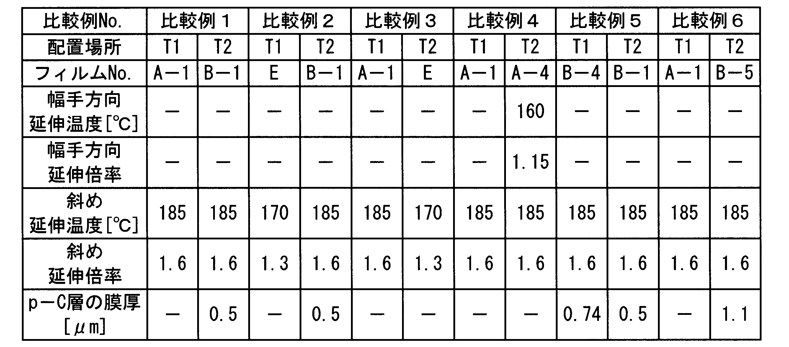

次に、上記で作製した各種位相差フィルムについて下記の評価を行った。
<位相差値等の測定>
フィルムの面内遅相軸方向θ、フィルムの面内方向位相差(リターデーション)値Ro、及び厚さ方向位相差値Rtの測定/評価は、位相差測定装置(王子計測社製、KOBRA-WXK)を用いて、フィルム流れ方向5m毎に幅方向にフィルムの50mmの間隔でRoの測定を行い、全データの平均値を面内方向位相差値Roとした。
フィルムの面内遅相軸方向θ、フィルムの面内方向位相差(リターデーション)値Ro、及び厚さ方向位相差値Rtの測定/評価は、位相差測定装置(王子計測社製、KOBRA-WXK)を用いて、フィルム流れ方向5m毎に幅方向にフィルムの50mmの間隔でRoの測定を行い、全データの平均値を面内方向位相差値Roとした。
また、フィルム厚さ方向の位相差値Rtは下記式を用いて算出した。
式(I):Ro=(nx-ny)×d
式(II):Rt={(nx+ny)/2-nz}×d
式中、nx、ny、nzは、23℃・55%RH、590nmにおける屈折率nx(フィルムの面内の最大の屈折率、遅相軸方向の屈折率ともいう。)、ny(フィルム面内で遅相軸に直交する方向の屈折率)、nzはフィルム厚さ方向における屈折率であり、dはフィルムの厚さ(nm)である。
式(II):Rt={(nx+ny)/2-nz}×d
式中、nx、ny、nzは、23℃・55%RH、590nmにおける屈折率nx(フィルムの面内の最大の屈折率、遅相軸方向の屈折率ともいう。)、ny(フィルム面内で遅相軸に直交する方向の屈折率)、nzはフィルム厚さ方向における屈折率であり、dはフィルムの厚さ(nm)である。
本発明の位相差フィルムの面内遅相軸方向を測定するには、フィルムの搬送方向を上記位相差測定装置の基準線(=0°)に合わせて位相差を測定する。面内遅相軸方向とは、上記の屈折率nxの方向である。よって、上記の位相差測定装置を使い、フィルムの搬送方向と装置の基準線を合わせれば、nxの方向も測定することができる。なお、測定結果は、表4に示す。
(3D-有機EL表示装置の作製)
《円偏光板の作製》
厚さ120μmのポリビニルアルコールフィルムを、一軸延伸(温度110℃、延伸倍率5倍)した。
《円偏光板の作製》
厚さ120μmのポリビニルアルコールフィルムを、一軸延伸(温度110℃、延伸倍率5倍)した。
これをヨウ素0.075g、ヨウ化カリウム5g、水100gからなる水溶液に60秒間浸漬し、次いでヨウ化カリウム6g、ホウ酸7.5g、水100gからなる68℃の水溶液に浸漬した。これを水洗、乾燥し偏光子を得た。巻き数は6000mとした。
上記作製した各フィルムを、完全ケン化型ポリビニルアルコール5%水溶液を粘着剤として、上記偏光子の両面に貼合した。その際、偏光子の透過軸とλ/4位相差フィルムの遅相軸が45度となるよう貼合した。偏光子の両面に貼る位相差フィルムの組み合わせは表4に示すとおりである。両面に位相差フィルムをロールtoロールで貼合し、偏光板を作製した。
《有機EL表示装置の作製》
次に、以下の手順で、有機エレクトロルミネッセンス表示装置を作製した。
次に、以下の手順で、有機エレクトロルミネッセンス表示装置を作製した。
本実施例の有機EL表示素子は、ガラス基板上にスパッタリング法によって厚さ80nmのクロムからなる反射電極、反射電極上に陽極としてITOをスパッタリング法で厚さ40nmに成膜し、陽極上に正孔輸送層としてポリ(3,4-エチレンジオキシチオフェン)-ポリスチレンスルホネート(PEDOT:PSS)をスパッタリング法で厚さ80nm、正孔輸送層上にシャドーマスクを用いて、RGBそれぞれの発光層を100nmの膜厚で形成した。赤色発光層としては、ホストとしてトリス(8-ヒドロキシキノリナート)アルミニウム(Alq3)と発光性化合物[4-(dicyanomethylene)-2-methyl-6(p-dimethylaminostyryl)-4H-pyran](DCM)とを共蒸着(質量比99:1)して100nmの厚さで形成した。緑色発光層としては、ホストとしてAlq3と、発光性化合物クマリン6(Coumarin6)とを共蒸着(質量比99:1)して100nmの厚さで形成した。青色発光層としては、ホストとしてBAlqと発光性化合物Peryleneとを共蒸着(質量比90:10)して厚さ100nmで形成した。

さらに、発光層上に電子が効率的に注入できるような仕事関数の低い第1の陰極としてカルシウムを真空蒸着法により4nmの厚さで成膜し、第1の陰極上に第2の陰極としてアルミニウムを2nmの厚さで成膜した。ここで、第2の陰極として用いたアルミニウムはその上に形成される透明電極をスパッタリング法により成膜する際に、第1の陰極であるカルシウムが化学的変質をすることを防ぐ役割がある。以上のようにして、有機発光層を得た。次に、陰極上にスパッタリング法によって透明導電膜を80nmの厚さで成膜した。ここで透明導電膜としてはITOを用いた。さらに、透明導電膜上にCVD法によって窒化珪素を200nm成膜することで、絶縁膜とした。
次に、上記作製した各円偏光板のT2のλ/4波長板の表面に接着層を塗工した後、図1(C)に示すように、上記のように製作した有機EL表示素子を用いて、T1とT2の配置が合うように貼合することで有機EL表示装置を作製した。
(3D-有機EL表示システムの評価)
上記で作製した有機EL表示装置と、液晶シャッター方式の3D眼鏡(SONY製3DメガネTDG-BR100)のパネル側に実施例及び比較例で作製したλ/4位相差フィルムを貼合した3D眼鏡を用いて、3D-有機EL表示システムを作製した。液晶シャッター方式の3D眼鏡は、パネル側から見て、位相差フィルム/液晶セル/偏光子がこの順番に設けられている。
上記で作製した有機EL表示装置と、液晶シャッター方式の3D眼鏡(SONY製3DメガネTDG-BR100)のパネル側に実施例及び比較例で作製したλ/4位相差フィルムを貼合した3D眼鏡を用いて、3D-有機EL表示システムを作製した。液晶シャッター方式の3D眼鏡は、パネル側から見て、位相差フィルム/液晶セル/偏光子がこの順番に設けられている。
上記作製した3D-有機EL表示システムについて、下記の各評価を行った。評価結果を表1に表示した。
作製した3D-有機EL表示装置について3D映像視聴時の首を傾けた際のクロストーク、連続点灯後の首を傾けない状態でのクロストーク、反射防止機能、色相(色味)変動について評価した。
《3D映像視聴時の首を傾けた際のクロストークの評価》
23℃・55%RHの環境下で、各々の液晶表示装置のバックライトを点灯させた直後、3D眼鏡をかけて、眼鏡が25°傾いた状態になるよう首を傾けた状態で3D映像を視聴し、クロストークを下記基準で評価した。
○:クロストークが全くない。
△:弱いクロストークが見える。
×:クロストークがはっきり見える。
23℃・55%RHの環境下で、各々の液晶表示装置のバックライトを点灯させた直後、3D眼鏡をかけて、眼鏡が25°傾いた状態になるよう首を傾けた状態で3D映像を視聴し、クロストークを下記基準で評価した。
○:クロストークが全くない。
△:弱いクロストークが見える。
×:クロストークがはっきり見える。
《正面の反射防止機能の評価》
正面の反射防止機能を下記基準に基づき評価した。
○:作製したEL表示装置を見たときに、自分や背景の画像が余り見えない。
△:作製したEL表示装置を見たときに、自分や背景の画像がうっすら見える。
×:作製したEL表示装置を見たときに、表示装置の画像と共に自分や背景の画像がはっきり見える。
正面の反射防止機能を下記基準に基づき評価した。
○:作製したEL表示装置を見たときに、自分や背景の画像が余り見えない。
△:作製したEL表示装置を見たときに、自分や背景の画像がうっすら見える。
×:作製したEL表示装置を見たときに、表示装置の画像と共に自分や背景の画像がはっきり見える。
《色相(色味)変動の評価》
作製した3D-有機EL表示装置について、画面全体を黒表示にし、画面に対して垂直方向を0°、垂直方向とパネルを見る目線とのなす角度を視角としたときに、視角60°であらゆる方向からパネルの色を評価した。
○:あらゆる方向からパネルを観察してもパネルの色味が黒のままほとんど変わらない。△:若干の色味の変動が見える。
×:明らかに色の変動が見られる。
作製した3D-有機EL表示装置について、画面全体を黒表示にし、画面に対して垂直方向を0°、垂直方向とパネルを見る目線とのなす角度を視角としたときに、視角60°であらゆる方向からパネルの色を評価した。
○:あらゆる方向からパネルを観察してもパネルの色味が黒のままほとんど変わらない。△:若干の色味の変動が見える。
×:明らかに色の変動が見られる。
以上の評価結果を表4に示す。
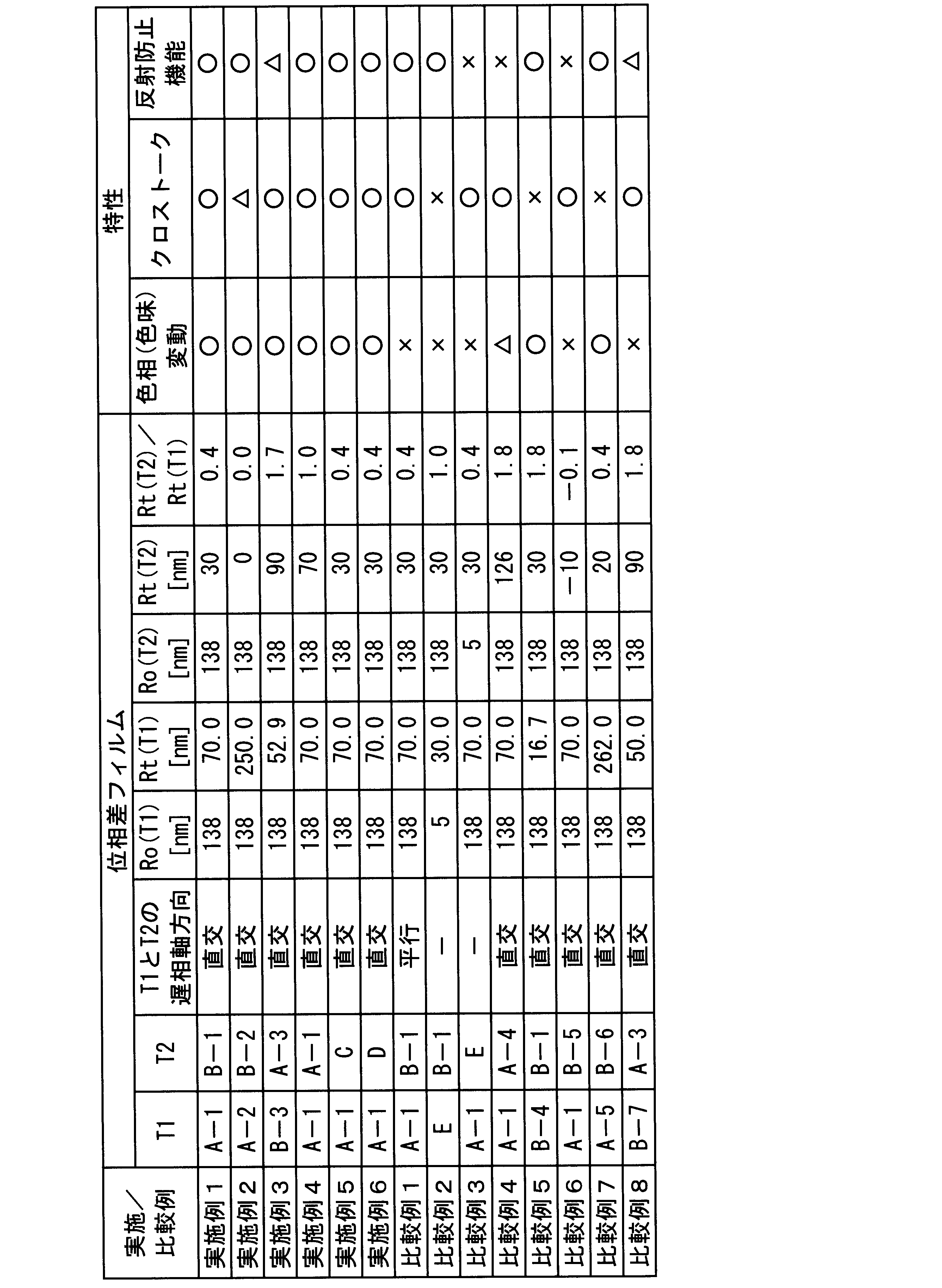
実施例1~6は色相(色味)変動が少なく、立体表示のクロストークも無かった。また、反射防止機能も十分であった。
一方、比較例1はT1とT2の位相差フィルムの遅相軸を平行に配置させているので、斜め方向から表示装置を観察したときの色の変化を抑制できないために色味変動が顕著に現れる。
また、比較例2は、T1に配置される位相差フィルムEの面内位相差値が5nmと小さいため、斜め方向から表示装置を観察したときの色相(色味)変動が見られ、また立体表示のクロストークも見られた。
比較例3は、T2に配置される位相差フィルムEの面内位相差値が5nmと小さいため、斜め方向から表示装置を観察したときの色相(色味)変動が見られ、反射防止機能も有していなかった。
比較例4は、Rt(T2)/Rt(T1)が、1.7を超えている。これはT2の位相差フィルムA-4のRtが100nmを超えているためである。T2の位相差フィルムのRtが100nmを超えていると、反射防止機能が低下してしまう。
比較例5も、比較例4と同様に、Rt(T2)/Rt(T1)が、1.7を超えている。これは、T1の位相差フィルムB-4のRtが20nm未満のためである。T1の位相差フィルムのRtが20nm未満だと、立体表示画像のクロストークが発生してしまう。特に、表示装置を斜めから見たときに、クロストークが激しく見られる。
比較例6は、Rt(T2)/Rt(T1)が負の値になっている。これは、T2の位相差フィルムA-4のRtが負の値を有しているからである。T2の位相差フィルムのRtが負の値を有していると、色相(色味)変動が大きくなり、反射防止機能も低下してしまう。
比較例7は、T1の位相差フィルムA-5のRtが250nmを超えてしまっている。T1の位相差フィルムのRtが250nmを超えてしまうと、立体表示画像のクロストークが顕著に起こってしまう。特に、表示装置を斜めから見たときに、クロストークが激しく見られる。
比較例8は、T1とT2の位相差フィルムのそれぞれのRtは、請求項1に記載の範囲内であるが、Rt(T2)/Rt(T1)の値が1.7を超えてしまっている。Rt(T2)/Rt(T1)の値が1.7を超えていると、色相(色味)変動が大きくなってしまう。
本発明の立体画像表示システムは、斜め方向の色相(色味)変化とクロストークを改善した立体画像表示システムであって、特に、有機エレクトロルミネッセンス素子が備えられた立体画像表示システムに適する。
a ガラス
b 反射電極
c 有機エレクトロルミネッセンス素子
d 酸化インジウムスズ(ITO)
e ガラス
f λ/4位相差フィルム(T2)
g 偏光子
h λ/4位相差フィルム(T1)
i 蛍光灯
j 位相差フィルム(T4)
k 偏光子
l 位相差フィルム(T3)
m 液晶セル+カラーフィルター
n 位相差フィルム(T2)
o 偏光子
p λ/4位相差フィルム(T1)
q λ/4位相差フィルム
r 液晶シャッター
s 偏光子
4 長尺フィルム原反
5 長尺延伸フィルム
6 斜め延伸テンター
7-1 外側のフィルム把持手段の軌跡
7-2 内側のフィルム把持手段の軌跡
8-1 外側のフィルム把持開始点
8-2 内側のフィルム把持開始点
9-1 外側のフィルム把持終了点
9-2 内側のフィルム把持終了点
10-1 外側斜め延伸開始点
10-2 内側斜め延伸開始点
11-1 外側斜め延伸終了点
11-2 内側斜め延伸終了点
11-3 外側横延伸ゾーン終点
12-1 テンター入口側のガイドローラ
12-2 テンター出口側のガイドローラ
13 フィルムの延伸方向
14-1 斜め延伸前のフィルムの搬送方向
14-2 斜め延伸後のフィルムの搬送方向
15 左右把持具同士の搬送速度が異なる部分
W0 斜め延伸前のフィルム幅手長さ
W 斜め延伸後のフィルム幅手長さ
16 フィルム繰り出し装置
17 搬送方向変更装置
18 巻き取り装置
19 製膜装置
1a 透明基盤
2a 金属電極
3aR 赤色発光層
3aG 緑色発光層
3aB 青色発光層
4a 透明電極
5a 絶縁膜
6a 接着層
7a λ/4板T2
8a 偏光子
9a λ/4板T1
10a 円偏光板
11a 有機EL表示基盤
b 反射電極
c 有機エレクトロルミネッセンス素子
d 酸化インジウムスズ(ITO)
e ガラス
f λ/4位相差フィルム(T2)
g 偏光子
h λ/4位相差フィルム(T1)
i 蛍光灯
j 位相差フィルム(T4)
k 偏光子
l 位相差フィルム(T3)
m 液晶セル+カラーフィルター
n 位相差フィルム(T2)
o 偏光子
p λ/4位相差フィルム(T1)
q λ/4位相差フィルム
r 液晶シャッター
s 偏光子
4 長尺フィルム原反
5 長尺延伸フィルム
6 斜め延伸テンター
7-1 外側のフィルム把持手段の軌跡
7-2 内側のフィルム把持手段の軌跡
8-1 外側のフィルム把持開始点
8-2 内側のフィルム把持開始点
9-1 外側のフィルム把持終了点
9-2 内側のフィルム把持終了点
10-1 外側斜め延伸開始点
10-2 内側斜め延伸開始点
11-1 外側斜め延伸終了点
11-2 内側斜め延伸終了点
11-3 外側横延伸ゾーン終点
12-1 テンター入口側のガイドローラ
12-2 テンター出口側のガイドローラ
13 フィルムの延伸方向
14-1 斜め延伸前のフィルムの搬送方向
14-2 斜め延伸後のフィルムの搬送方向
15 左右把持具同士の搬送速度が異なる部分
W0 斜め延伸前のフィルム幅手長さ
W 斜め延伸後のフィルム幅手長さ
16 フィルム繰り出し装置
17 搬送方向変更装置
18 巻き取り装置
19 製膜装置
1a 透明基盤
2a 金属電極
3aR 赤色発光層
3aG 緑色発光層
3aB 青色発光層
4a 透明電極
5a 絶縁膜
6a 接着層
7a λ/4板T2
8a 偏光子
9a λ/4板T1
10a 円偏光板
11a 有機EL表示基盤
Claims (4)
- 少なくとも偏光板と発光素子とを有する画像表示装置と、少なくとも偏光子を有する眼鏡とで構成される立体画像表示システムであって、前記偏光板が、下記要件(a)~(c)を満たすことを特徴とする立体画像表示システム。
(a)前記偏光板は、長尺ロールから繰り出された偏光子の両面に、下記の光学特性を有する位相差フィルムが、当該偏光子の長尺方向と同じ方向に、長尺ロールから繰り出して貼合されて形成されたものである。
(b)前記偏光子の両面に貼合された位相差フィルムの遅相軸は、偏光子の長尺方向と幅手方向とは異なる両者の間の方向にあり、かつ偏光子の両面にある位相差フィルムの遅相軸が互いに直交する方向に貼合されている。
(c)温度23℃・相対湿度55%の環境下、光波長550nmで測定した、前記位相差フィルムの面内位相差値Roと厚さ方向の位相差値Rtとが、それぞれ、下記式(1)~(4)を満たす。
式(1):108nm≦Ro≦168nm
式(2):20nm≦Rt(T1)≦250nm
式(3):0nm≦Rt(T2)≦100nm
式(4):0≦Rt(T2)/Rt(T1)≦1.7
(ただし、Rt(T1)は、前記発光素子に積層されている偏光板の偏光子の視認側に貼合された位相差フィルムT1の厚さ方向の位相差値Rtを表す。Rt(T2)は、前記発光素子に積層されている偏光板の偏光子の発光素子側に貼合された位相差フィルムT2の厚さ方向の位相差値Rtを表す。) - 前記発光素子が、有機エレクトロルミネッセンス素子であることを特徴とする請求項1に記載の立体画像表示システム。
- 前記位相差フィルムが、総アシル基置換度が2.0~2.6の範囲内にあるセルロースエステルを含有していることを特徴とする請求項1又は請求項2に記載の立体画像表示システム。
- 前記眼鏡が、液晶シャッター方式の眼鏡であることを特徴とする請求項1から請求項3までのいずれか一項に記載の立体画像表示システム。
Priority Applications (1)
| Application Number | Priority Date | Filing Date | Title |
|---|---|---|---|
| JP2013536019A JP5915660B2 (ja) | 2011-09-28 | 2012-07-27 | 立体画像表示システム |
Applications Claiming Priority (2)
| Application Number | Priority Date | Filing Date | Title |
|---|---|---|---|
| JP2011-211965 | 2011-09-28 | ||
| JP2011211965 | 2011-09-28 |
Publications (1)
| Publication Number | Publication Date |
|---|---|
| WO2013046897A1 true WO2013046897A1 (ja) | 2013-04-04 |
Family
ID=47994951
Family Applications (1)
| Application Number | Title | Priority Date | Filing Date |
|---|---|---|---|
| PCT/JP2012/069087 Ceased WO2013046897A1 (ja) | 2011-09-28 | 2012-07-27 | 立体画像表示システム |
Country Status (2)
| Country | Link |
|---|---|
| JP (1) | JP5915660B2 (ja) |
| WO (1) | WO2013046897A1 (ja) |
Cited By (4)
| Publication number | Priority date | Publication date | Assignee | Title |
|---|---|---|---|---|
| JP2013114768A (ja) * | 2011-11-25 | 2013-06-10 | Konica Minolta Advanced Layers Inc | 有機エレクトロルミネッセンス立体画像表示システム |
| WO2019059067A1 (ja) * | 2017-09-22 | 2019-03-28 | 日本ゼオン株式会社 | 真正性判定用ビュワー |
| WO2021045154A1 (ja) * | 2019-09-06 | 2021-03-11 | 三菱瓦斯化学株式会社 | ポリカーボネート樹脂組成物 |
| CN115394189A (zh) * | 2018-09-28 | 2022-11-25 | 东洋纺株式会社 | 带指纹验证传感器的图像显示装置 |
Citations (6)
| Publication number | Priority date | Publication date | Assignee | Title |
|---|---|---|---|---|
| JP2009157352A (ja) * | 2007-12-06 | 2009-07-16 | Nitto Denko Corp | 偏光板、その製造方法、光学フィルムおよび画像表示装置 |
| WO2010125997A1 (ja) * | 2009-04-27 | 2010-11-04 | コニカミノルタオプト株式会社 | 偏光板、偏光板の製造方法及び液晶表示装置 |
| JP2010262145A (ja) * | 2009-05-08 | 2010-11-18 | Nitto Denko Corp | 映像鑑賞設備 |
| WO2011058784A1 (ja) * | 2009-11-13 | 2011-05-19 | シャープ株式会社 | 立体映像認識システム、映像表示装置及びアクティブシャッターメガネ |
| JP2011137853A (ja) * | 2009-12-25 | 2011-07-14 | Nitto Denko Corp | 立体映像表示用位相差板、偏光素子およびそれらの製造方法、ならびに立体映像表示装置 |
| JP2011164816A (ja) * | 2010-02-08 | 2011-08-25 | Nippon Shokubai Co Ltd | タッチパネルおよびタッチパネル付き表示装置 |
-
2012
- 2012-07-27 JP JP2013536019A patent/JP5915660B2/ja not_active Expired - Fee Related
- 2012-07-27 WO PCT/JP2012/069087 patent/WO2013046897A1/ja not_active Ceased
Patent Citations (6)
| Publication number | Priority date | Publication date | Assignee | Title |
|---|---|---|---|---|
| JP2009157352A (ja) * | 2007-12-06 | 2009-07-16 | Nitto Denko Corp | 偏光板、その製造方法、光学フィルムおよび画像表示装置 |
| WO2010125997A1 (ja) * | 2009-04-27 | 2010-11-04 | コニカミノルタオプト株式会社 | 偏光板、偏光板の製造方法及び液晶表示装置 |
| JP2010262145A (ja) * | 2009-05-08 | 2010-11-18 | Nitto Denko Corp | 映像鑑賞設備 |
| WO2011058784A1 (ja) * | 2009-11-13 | 2011-05-19 | シャープ株式会社 | 立体映像認識システム、映像表示装置及びアクティブシャッターメガネ |
| JP2011137853A (ja) * | 2009-12-25 | 2011-07-14 | Nitto Denko Corp | 立体映像表示用位相差板、偏光素子およびそれらの製造方法、ならびに立体映像表示装置 |
| JP2011164816A (ja) * | 2010-02-08 | 2011-08-25 | Nippon Shokubai Co Ltd | タッチパネルおよびタッチパネル付き表示装置 |
Cited By (8)
| Publication number | Priority date | Publication date | Assignee | Title |
|---|---|---|---|---|
| JP2013114768A (ja) * | 2011-11-25 | 2013-06-10 | Konica Minolta Advanced Layers Inc | 有機エレクトロルミネッセンス立体画像表示システム |
| WO2019059067A1 (ja) * | 2017-09-22 | 2019-03-28 | 日本ゼオン株式会社 | 真正性判定用ビュワー |
| JPWO2019059067A1 (ja) * | 2017-09-22 | 2020-09-03 | 日本ゼオン株式会社 | 真正性判定用ビュワー |
| EP3686635A4 (en) * | 2017-09-22 | 2021-06-02 | Zeon Corporation | VIEWER FOR DETERMINATION |
| US11442211B2 (en) | 2017-09-22 | 2022-09-13 | Zeon Corporation | Viewer for determination of authenticity |
| JP7264055B2 (ja) | 2017-09-22 | 2023-04-25 | 日本ゼオン株式会社 | 真正性判定用ビュワー |
| CN115394189A (zh) * | 2018-09-28 | 2022-11-25 | 东洋纺株式会社 | 带指纹验证传感器的图像显示装置 |
| WO2021045154A1 (ja) * | 2019-09-06 | 2021-03-11 | 三菱瓦斯化学株式会社 | ポリカーボネート樹脂組成物 |
Also Published As
| Publication number | Publication date |
|---|---|
| JP5915660B2 (ja) | 2016-05-11 |
| JPWO2013046897A1 (ja) | 2015-03-26 |
Similar Documents
| Publication | Publication Date | Title |
|---|---|---|
| JP6617494B2 (ja) | 斜め延伸フィルムの製造方法 | |
| JP2008083307A (ja) | 偏光板、偏光板の製造方法、及び液晶表示装置 | |
| WO2008041657A1 (en) | Polycycloolefin resin film, process for producing the same, polarizer, and liquid-crystal display | |
| JP2013156391A (ja) | ロール状円偏光板の製造方法、有機エレクトロルミネッセンス表示装置及び横電界型スイッチングモード型液晶表示装置 | |
| WO2012014595A1 (ja) | 立体映像表示装置 | |
| JP5996163B2 (ja) | 光学フィルムの製造方法、偏光板及び画像表示装置 | |
| JP6923048B2 (ja) | 斜め延伸フィルムの製造方法 | |
| JP5707811B2 (ja) | 長尺状λ/4板、円偏光板、偏光板、OLED表示装置、及び立体画像表示装置 | |
| JP5565281B2 (ja) | 斜め延伸フィルムの製造方法、及び光学フィルムの製造方法 | |
| JPWO2016152384A1 (ja) | 斜め延伸フィルムの製造方法 | |
| KR102085413B1 (ko) | 긴 광학 필름, 그 제조 방법, 편광판 및 표시 장치 | |
| JP5915660B2 (ja) | 立体画像表示システム | |
| JP2007079533A (ja) | 光学樹脂フィルム、これを用いた偏光板および液晶表示装置 | |
| WO2014192681A1 (ja) | 樹脂組成物、光学部材、光学フィルム、偏光板、円偏光板及び画像表示装置 | |
| JP5589648B2 (ja) | ハードコート付きλ/4板、その製造方法、偏光板、液晶表示装置、及びタッチパネル部材 | |
| JPWO2007132615A1 (ja) | セルロースアシレートフィルムの製造方法、セルロースアシレートフィルム、偏光板及び液晶表示装置 | |
| KR101112443B1 (ko) | 셀룰로오스 필름, 편광판 및 액정 표시 장치 | |
| JP5971198B2 (ja) | 偏光板とその製造方法、及びそれを具備した有機エレクトロルミネッセンス表示装置 | |
| JP2012173677A (ja) | 位相差フィルムとその製造方法、長尺状偏光板、及び液晶表示装置 | |
| JP6044541B2 (ja) | 長尺延伸フィルムの製造方法及び円偏光板の製造方法 | |
| JP2004020827A (ja) | 円偏光板とその製造方法および液晶表示装置 | |
| JP5521832B2 (ja) | λ/4板及び立体映像表示装置 | |
| JP5569323B2 (ja) | 長尺延伸フィルムの製造方法、及び長尺偏光板の製造方法 | |
| JP2012101466A (ja) | 長尺状延伸フィルムとその製造方法、長尺状偏光板、及び液晶表示装置 | |
| JP2012230282A (ja) | λ/4位相差フィルムの製造方法、長尺状偏光板、及び液晶表示装置 |
Legal Events
| Date | Code | Title | Description |
|---|---|---|---|
| 121 | Ep: the epo has been informed by wipo that ep was designated in this application |
Ref document number: 12835186 Country of ref document: EP Kind code of ref document: A1 |
|
| ENP | Entry into the national phase |
Ref document number: 2013536019 Country of ref document: JP Kind code of ref document: A |
|
| NENP | Non-entry into the national phase |
Ref country code: DE |
|
| 122 | Ep: pct application non-entry in european phase |
Ref document number: 12835186 Country of ref document: EP Kind code of ref document: A1 |