WO2013046599A1 - 画像処理装置及びそれを用いた印刷装置並びにそのプログラム - Google Patents
画像処理装置及びそれを用いた印刷装置並びにそのプログラム Download PDFInfo
- Publication number
- WO2013046599A1 WO2013046599A1 PCT/JP2012/005947 JP2012005947W WO2013046599A1 WO 2013046599 A1 WO2013046599 A1 WO 2013046599A1 JP 2012005947 W JP2012005947 W JP 2012005947W WO 2013046599 A1 WO2013046599 A1 WO 2013046599A1
- Authority
- WO
- WIPO (PCT)
- Prior art keywords
- resolution
- data
- low
- processing
- image
- Prior art date
- Legal status (The legal status is an assumption and is not a legal conclusion. Google has not performed a legal analysis and makes no representation as to the accuracy of the status listed.)
- Ceased
Links
Images



Classifications
-
- G—PHYSICS
- G06—COMPUTING OR CALCULATING; COUNTING
- G06K—GRAPHICAL DATA READING; PRESENTATION OF DATA; RECORD CARRIERS; HANDLING RECORD CARRIERS
- G06K15/00—Arrangements for producing a permanent visual presentation of the output data, e.g. computer output printers
- G06K15/02—Arrangements for producing a permanent visual presentation of the output data, e.g. computer output printers using printers
- G06K15/18—Conditioning data for presenting it to the physical printing elements
- G06K15/1867—Post-processing of the composed and rasterized print image
- G06K15/1872—Image enhancement
- G06K15/1876—Decreasing spatial resolution; Dithering
-
- B—PERFORMING OPERATIONS; TRANSPORTING
- B41—PRINTING; LINING MACHINES; TYPEWRITERS; STAMPS
- B41J—TYPEWRITERS; SELECTIVE PRINTING MECHANISMS, i.e. MECHANISMS PRINTING OTHERWISE THAN FROM A FORME; CORRECTION OF TYPOGRAPHICAL ERRORS
- B41J2/00—Typewriters or selective printing mechanisms characterised by the printing or marking process for which they are designed
- B41J2/005—Typewriters or selective printing mechanisms characterised by the printing or marking process for which they are designed characterised by bringing liquid or particles selectively into contact with a printing material
- B41J2/01—Ink jet
- B41J2/21—Ink jet for multi-colour printing
- B41J2/2107—Ink jet for multi-colour printing characterised by the ink properties
- B41J2/2114—Ejecting specialized liquids, e.g. transparent or processing liquids
Definitions
- the present invention provides image processing that generates data for coating processing that does not directly contribute to image formation, such as overcoat processing that covers a printed region and undercoat processing that covers a region printed before printing.
- the present invention relates to an apparatus, a printing apparatus using the apparatus, and a program thereof.
- this type of apparatus includes a print head that ejects ink onto a print sheet, and an overcoat unit that is disposed on the downstream side of the print head in the direction in which the print sheet is fed (for example, Patent Document 1).
- ink is ejected onto the printing paper by the print head according to the print data of the image including characters. Then, in the overcoat portion on the downstream side of the print head, the overcoat material is transferred and the overcoat process is performed on the area where the ink is ejected. This prevents the ink from fading.
- the periphery of the image is thickened by one pixel in accordance with the print data, and the overcoat material is transferred by one pixel wider than the area where the ink has been deposited.
- the conventional example having such a configuration has the following problems. That is, when performing the overcoat process, the conventional apparatus performs a process in which the periphery of the image is thickened by one pixel while maintaining a high resolution.
- the present invention has been made in view of such circumstances, and an image processing apparatus capable of reducing processing time by generating low resolution coating data and printing using the same
- An object is to provide an apparatus and a program thereof.
- the present invention has the following configuration. That is, according to the present invention, in an image processing apparatus that generates coat processing data based on input image data, the input image data is rasterized at a high resolution in accordance with the resolution of the print head, and a high resolution raster image is generated.
- a coat processing data generating unit that generates coat processing data based on the low resolution raster image.
- the print data is generated by the print data generation unit based on the high resolution raster image generated by the high resolution rasterization processing unit.
- the low resolution rasterization processing unit generates a low resolution raster image having a lower resolution than the high resolution raster image
- the coating processing data is generated by the coating processing data generation unit based on the low resolution raster image. Since the data for coating processing is handled at a low resolution, the processing time required for generating the coating processing data can be shortened compared to the case of handling at a high resolution.
- the “coating process” of the coating process data here means “undercoat process” in which the coating process is performed on the printing paper in the area corresponding to the printing area before the printing process, or printing after the printing process.
- This is an “overcoat process” in which a coating process is performed on printing paper in an area corresponding to the area.
- the undercoat process is a process for improving the paper quality of the printing paper so that, for example, the ink is less likely to spread on the printing paper or is stabilized inside the printing paper.
- the overcoat process is a process for stabilizing a printed image.
- the overcoat process is a process for preventing the ink deposited on the printing paper from fading or peeling off.
- the input image data is composed of color data
- the low-resolution rasterization processing unit generates the low-resolution raster image for each color from the input image data, and generates the low-resolution raster image for each color. It is preferable to further include a synthesizing unit that synthesizes the data with the low resolution and outputs it to the data processing unit for coat processing.
- the low resolution rasterization processing unit When the input image data is color data, the low resolution rasterization processing unit generates a low resolution raster image for each color of the input image data.
- the synthesizing unit synthesizes the low resolution raster image for each color with the low resolution and outputs the synthesized image to the coat processing data generation unit. Since a low-resolution raster image is generated and combined for each color, even for a low-resolution raster image, data for coat processing can be generated relatively faithfully in each color area.
- the input image data is composed of color data
- the low resolution rasterization processing unit generates the low resolution raster image using the input image data as a monochrome image.
- the low resolution rasterization processing unit When the input image data is color data, the low resolution rasterization processing unit generates a low resolution raster image using the input image data as a monochrome image. Therefore, it is not necessary to perform low resolution rasterization for each color, and coat processing data can be generated more efficiently.
- the present invention also relates to a printing apparatus that performs printing processing of an image on printing paper based on input image data and coating processing on printing paper using coating processing data based on input image data according to the resolution of the print head.
- a high resolution rasterization processing unit that rasterizes the input image data at a high resolution and generates a high resolution raster image; and a low resolution that rasterizes the input image data at a resolution lower than the resolution to generate a low resolution raster image.
- a rasterization processing unit a print data generation unit that generates print data corresponding to a print head based on the high resolution raster image, and a coat processing data generation unit that generates coat processing data based on the low resolution raster image On the printing paper based on the high-resolution raster image.
- a print head for printing a and is characterized in that it comprises a coating treatment head for coat treatment, against the printing paper based on the coating process data.
- the print data is generated by the print data generation unit based on the high resolution raster image generated by the high resolution rasterization processing unit.
- the low resolution rasterization processing unit generates a low resolution raster image having a lower resolution than the high resolution raster image
- the coating processing data is generated by the coating processing data generation unit based on the low resolution raster image. Since the data for coating processing is handled at a low resolution, the processing time required for generating the coating processing data can be shortened compared to the case of handling at a high resolution.
- the print head prints an image faithfully based on the high-resolution raster image, and the coat processing head roughly performs the coat process based on the data for the coat process, thereby reducing the time required for the printing process on the printing paper. it can.
- the input image data is rasterized at a high resolution according to the resolution of the print head.
- a high resolution rasterization process for generating a resolution raster image, a low resolution rasterization process for generating a low resolution raster image by rasterizing the input image data at a lower resolution than the resolution, and a print head based on the high resolution raster image Print data generation processing for generating print data corresponding to the image data, and coat processing data generation processing for generating data for coat processing based on the low resolution raster image.
- the print data is generated by the print data generation process based on the high resolution raster image generated by the high resolution rasterization process.
- the coat processing data is generated by low-resolution rasterization processing to generate a low-resolution raster image having a resolution lower than that of the high-resolution raster image, and is generated by coating-processing data generation processing based on the low-resolution raster image. Since the coating process data is handled at a low resolution, it is possible to realize a program that shortens the processing time required for the coating process compared to the case of handling at a high resolution.
- the print data is generated by the print data generation unit based on the high resolution raster image generated by the high resolution rasterization processing unit.
- the low resolution rasterization processing unit generates a low resolution raster image having a lower resolution than the high resolution raster image
- the coating processing data is generated by the coating processing data generation unit based on the low resolution raster image. Since the data for the coating process is handled at a low resolution, the processing time required for the coating process can be shortened compared to the case of handling at a high resolution.
- FIG. 1 is a schematic configuration diagram illustrating an entire inkjet printing system according to Embodiment 1.
- FIG. 1 is a block diagram illustrating an image processing apparatus according to a first embodiment. It is a schematic diagram which shows the low resolution rasterization process and the data generation process for a coat process, (a) shows input image data, (b) shows Y data, (c) shows C data, (d ) Shows data for M, (e) shows data for K, and (f) shows data for overcoat processing. It is a flowchart which shows a printing process.
- FIG. 6 is a block diagram illustrating an image processing apparatus according to a second embodiment. It is a schematic diagram which shows the low resolution rasterization process and the data production
- the image processing apparatus, printing apparatus, and program thereof will be described below by taking an inkjet printing system as an example.
- FIG. 1 is a schematic configuration diagram illustrating the entire inkjet printing system according to the first embodiment.
- the ink jet printing system includes a paper feeding unit 1, an ink jet printing apparatus 3, and a paper discharge unit 5.
- the paper supply unit 1 supplies, for example, a roll-shaped continuous paper WP that is a printing target.
- the ink jet printing apparatus 3 performs printing on the supplied continuous paper WP.
- the paper discharge unit 5 winds the printed continuous paper WP into a roll.
- the paper feed unit 1 holds the roll-shaped continuous paper WP so as to be rotatable around a horizontal axis, and unwinds and supplies the continuous paper WP to the inkjet printing apparatus 3.
- the paper discharge unit 5 winds the continuous paper WP printed by the inkjet printer 3 around the horizontal axis. If the supply side of the continuous paper WP is the upstream side and the discharge side of the continuous paper WP is the downstream side, the paper feed unit 1 is disposed on the upstream side of the ink jet printing apparatus 3, and the paper discharge unit 5 is on the downstream side of the ink jet printing apparatus 3. Is arranged.
- the inkjet printing apparatus 3 includes a driving roller 7 for taking in the continuous paper WP from the paper feeding unit 1 on the upstream side.
- the continuous paper WP unwound from the paper feeding unit 1 by the driving roller 7 is conveyed along the plurality of conveying rollers 9 toward the paper discharge unit 5 on the downstream side.
- a driving roller 11 is arranged between the most downstream conveying roller 9 and the paper discharge unit 5. The drive roller 11 feeds the continuous paper WP conveyed on the conveyance roller 9 toward the paper discharge unit 5.
- the inkjet printing apparatus 3 includes a printing unit 13, an overcoat processing unit 14, a drying unit 15, and an inspection unit 17 in this order from the upstream side between the driving roller 7 and the driving roller 11.
- the drying unit 15 dries a portion printed by the printing unit 13.
- the inspecting unit 17 inspects the printed part for dirt or omissions.
- the printing unit 13 includes an ink discharge head 19 that discharges ink droplets.
- a plurality of ink ejection heads 19 are arranged along the conveyance direction of the continuous paper WP.
- four ink ejection heads 19K, 19C, 19M, and 19Y are individually provided for black (K), cyan (C), and magenta (M) yellow (Y).
- Each of the ink ejection heads 19K, 19C, 19M, and 19Y includes a plurality of ink ejection heads 19K, 19C, 19M, and 19Y in a horizontal direction (width direction) orthogonal to the conveyance direction of the continuous paper WP.
- Each of the ink discharge heads 19K, 19C, 19M, and 19Y includes a plurality of ink discharge heads 19K, 19C, 19M, and 19Y in the width direction of the continuous paper WP that can be printed without moving the print area in the width direction of the continuous paper WP. ing. That is, the ink jet printing apparatus 3 in this embodiment does not move the ink ejection heads 19K, 19C, 19M, and 19Y for main scanning in the horizontal direction orthogonal to the conveyance direction of the continuous paper WP, and remains fixed in position. The printing is performed on the continuous paper WP while feeding the continuous paper WP. This method is called a one-pass method.
- the ink discharge heads 19K, 19C, 19M, and 19Y correspond to the “print head” in the present invention.
- the overcoat processing unit 14 disposed on the downstream side of the printing unit 13 performs overcoat processing on the continuous paper WP on which ink has been deposited.
- the overcoat process is performed on the area where the image is printed by the printing unit 13.
- an overcoat material for preventing ink fading is discharged from the overcoat discharge head 14 ⁇ / b> C so as to widely cover a region where ink has been ejected.
- the overcoat discharge head 14 ⁇ / b> C has the same configuration as the ink discharge head 19, and the discharged material is different.
- the overcoat discharge head 14C corresponds to the “coat processing head” in the present invention.
- the printing unit 13 and the overcoat processing unit 14 print an image or discharge an overcoat material based on data received from the image processing device 21 as described later.
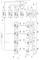
- FIG. 2 is a block diagram illustrating the image processing apparatus according to the first embodiment.
- the image processing apparatus 21 includes a high-resolution rasterization processing unit 23, a print data generation unit 25, a low-resolution rasterization processing unit 27, a synthesis unit 29, and an overcoat processing data generation unit 31.
- the high resolution rasterization processing unit 23 includes a high resolution rasterization processing unit 23K for K, a high resolution rasterization processing unit 23C for C, a high resolution rasterization processing unit 23M for M, and a high resolution rasterization processing unit 23Y for Y. And.
- the high resolution rasterization processing unit 23 rasterizes each color at a high resolution in accordance with the resolution of the ink ejection head 19 to generate a high resolution raster image.
- Rasterization is a process of converting vector image information into a raster image necessary for printing. By this processing, a high resolution raster image is generated for each color.
- the print data generation unit 25 corresponds to each color of the high-resolution rasterization processing unit 23, the K print data generation unit 25K, the C print data generation unit 25C, and the M print data generation unit 25M. , Y print data generation unit 25Y.
- the printing data generation unit 25 for each color is connected corresponding to each color of the high resolution rasterization processing unit 23.
- the print data generation unit 25 generates print data corresponding to the ink ejection heads 19 for each color based on the high resolution raster image from the high resolution rasterization processing unit 23. More specifically, halftone processing is performed on the high-resolution raster image in accordance with the ink ejection heads 19 for each color, and print data is generated.
- the ink discharge head 19 includes a K ink discharge head 19K, a C ink discharge head 19C, an M ink discharge head 19M, and a Y ink discharge head 19Y. Connected to correspond to.
- the ink discharge head 19 adjusts the size of the ink droplets according to the gradation of the halftoned print data, and discharges the ink toward the continuous paper WP.
- the low resolution rasterization processing unit 27 includes a low resolution rasterization processing unit 27K for K, a low resolution rasterization processing unit 27C for C, a low resolution rasterization processing unit 27M for M, and a low resolution rasterization processing unit 27Y for Y. And.
- the low resolution rasterization processing unit 27 performs rasterization of each color at a resolution lower than the resolution of the ink ejection head 19 based on the input image data, and generates a low resolution raster image.
- the low resolution is, for example, 1/4 of the resolution of the ink ejection head 19.
- the synthesizing unit 29 synthesizes the low-resolution raster image of each color generated by the low-resolution rasterization processing unit 27 by performing an OR operation while maintaining the low resolution.
- the overcoat processing data generation unit 31 generates overcoat processing data based on the synthesized low-resolution raster image. Specifically, the combined low-resolution raster image is subjected to a halftoning process that adds water to the overcoat discharge head 14C. The overcoat processing data generated in this way is given to the overcoat discharge head 14C, and the overcoat material is discharged only to the area corresponding to the overcoat processing data that has been subjected to the halftoning process.
- the overcoat processing data generation unit 31 corresponds to the “coat processing data generation unit” in the present invention.
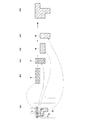
- FIG. 3 is a schematic diagram showing low resolution rasterization processing and overcoat processing data generation processing, where (a) shows input image data, (b) shows Y data, and (c) shows C data. (D) shows data for M, (e) shows data for K, and (f) shows data for overcoat processing.
- the low resolution rasterization processing unit 27 converts the resolution to 1/4 for the input image data. For example, as shown by a dotted line in FIG. 3A, the low resolution rasterization processing unit 27 assumes a mesh that is 1/4 of the resolution of the input image data, and the input image data is one pixel in one of the meshes. However, if it exists, it is converted so that the data exists in one of the meshes. Therefore, the Y data of the input image data that has a horizontally long rectangular shape in FIG. 3A is greatly extended in the vertical direction as shown in FIG. 3B, and is also extended in the right horizontal direction. Similarly, as shown in FIG. 3C, the C data of the input image data is extended up and down and is also extended in the left lateral direction.
- the M data of the input image data is extended to the left and right and extended downward in the vertical direction.
- the K data of the input image data is extended in the vertical direction and the left direction.
- the overcoat processing data in this embodiment does not perform the fattening process around the input image data by one pixel, but merely generates a logical sum of the low resolution rasterized images after the low resolution rasterized image is generated. Data for overcoat processing can be generated at high speed.
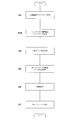
- FIG. 4 is a flowchart showing the printing process.
- Step S1 Perform high-resolution rasterization.
- the high resolution rasterization processing unit 23 (23K, 23C, 23M, 23Y) rasterizes each color at a high resolution in accordance with the resolution of the ink ejection head 19 to generate a high resolution raster image.
- Step S2 Low resolution rasterization processing is performed for each color.
- the low resolution rasterization processing unit 27 (27K, 27C, 27M, 27Y) rasterizes each color at a resolution lower than the resolution of the ink ejection head 19 based on the input image data, and generates a low resolution raster image.
- Step S3 Print data generation processing is performed.
- the print data generation unit 25 (25K, 25C, 25M, 25Y) generates print data corresponding to the ink ejection heads 19 of each color based on the high resolution raster image from the high resolution rasterization processing unit 23.
- Step S4 Perform synthesis processing.
- the combining unit 29 combines the low-resolution raster images of the respective colors generated by the low-resolution rasterization processing unit 27.
- Step S5 The overcoat processing data generation unit 31 generates overcoat processing data based on the synthesized low-resolution raster image.
- Step S6 Perform the printing process.
- the ink ejection head 19 (19K, 19C, 19M, 19Y) ejects ink droplets according to the print data of each color, and forms an image on the continuous paper WP.
- Step S7 Perform overcoat treatment.
- the overcoat discharge head 14C discharges the overcoat material in accordance with the overcoat processing data, and roughly performs the overcoat processing so as to cover the area of the continuous paper WP where the image is formed.
- the print data is generated by the print data generation unit 25 based on the high resolution raster image generated by the high resolution rasterization processing unit 23.
- a low resolution raster image having a lower resolution than the high resolution raster image is generated by the low resolution rasterization processing unit 27, and the overcoat processing data generating unit 31 generates the low resolution raster image based on the low resolution raster image.
- the overcoat processing data is handled at a low resolution, the processing time required for the overcoat processing can be shortened as compared with the case of handling at a high resolution.
- the ink discharge head 19 faithfully prints an image based on the high resolution raster image, and the overcoat discharge head 14C roughly performs the overcoat processing based on the overcoat processing data. Processing time can be shortened.
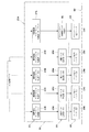
- FIG. 5 is a block diagram illustrating an image processing apparatus according to the second embodiment.
- the inkjet printing system has the same configuration as that of the first embodiment described above, and is not shown in the figure. Further, the same components as those in the first embodiment are denoted by the same reference numerals, and detailed description thereof is omitted.
- Example 2 This example is different from Example 1 in which the image processing unit 21A is described above. Specifically, the low resolution rasterization processing unit 27A is different.
- the low resolution rasterization processing unit 27A treats the input image data as a monochrome image and generates a low resolution raster image.
- the overcoat processing data generation unit 31 generates overcoat processing data based on the generated low-resolution raster image. More specifically, the generated low-resolution raster image is subjected to a padding halftoning process in accordance with the overcoat ejection head 14C.
- the overcoat discharge head 14 ⁇ / b> C discharges the overcoat material only to a region corresponding to the overcoat processing data subjected to the water addition and halftoning process.
- FIG. 6 is a schematic diagram showing low resolution rasterization processing and overcoat processing data generation processing, where (a) shows input image data and (b) shows data for overcoat processing.
- the low resolution rasterization processing unit 27A converts the resolution to 1 ⁇ 4 for the input image data.
- the input image data is not converted for each color, but is converted after being handled as monochrome.
- the colors Y, C, M, and K of the input image data are treated equally, and as shown in FIG. 6 (a), whether or not one of the meshes simply has a pixel value of 1 or more.
- a low resolution raster image is generated, and overcoat processing data is generated as shown in FIG.
- FIG. 7 is a flowchart showing the printing process.
- Steps S1, S3, S5 to S7 are the same as those in the first embodiment.
- the apparatus according to the present embodiment is different from Step S2A in that Step S4 in Embodiment 1 is not provided.
- Step S2A Perform low-resolution rasterization processing in monochrome.
- the low-resolution rasterization processing unit 27 performs monochrome rasterization at a resolution lower than the resolution of the ink ejection head 19 based on the input image data, and generates a low-resolution raster image.
- the overcoat process data generation process is performed based on the low resolution raster image generated in this way (step S5), the print process is performed (step S6), and the overcoat process is performed (step S7).
- the low resolution rasterization processing unit 27A when the input image data is color data, the low resolution rasterization processing unit 27A generates a low resolution raster image using the input image data as a monochrome image. Therefore, it is not necessary to perform low resolution rasterization for each color, and the overcoat processing data can be generated more efficiently.
- the present invention is not limited to the above embodiment, and can be modified as follows.
- the overcoat treatment is taken as an example of the coat treatment, but the present invention can also be applied to the undercoat treatment.
- an undercoat discharge head may be provided upstream of the printing unit 13 in place of the overcoat discharge head 14C.
- both an overcoat process and an undercoat process may be provided.
- the present invention can also be applied to a coating process that does not contribute to image formation in printing, other than an overcoat process or an undercoat process.
- the resolution is set to 1/4 of the resolution of the ink discharge head 19 as a low resolution. It is not limited.
- the so-called one-pass inkjet printing apparatus 3 is taken as an example.
- the present invention is not limited to this scheme, and the so-called multi-pass inkjet printing apparatus. 3 is also applicable.
- the present invention is suitable for an image processing apparatus that generates data for coating processing that does not directly contribute to image formation, a printing apparatus using the same, and a program thereof.
Landscapes
- Engineering & Computer Science (AREA)
- General Engineering & Computer Science (AREA)
- Physics & Mathematics (AREA)
- General Physics & Mathematics (AREA)
- Theoretical Computer Science (AREA)
- Ink Jet (AREA)
- Record Information Processing For Printing (AREA)
Abstract
印刷データは、高解像度ラスタライズ処理部23により生成された高解像度ラスターイメージに基づいて印刷データ生成部25により生成される。一方、コート処理用データは、低解像度ラスタライズ処理部27により、高解像度ラスターイメージよりも低解像度の低解像度ラスターイメージが生成され、この低解像度ラスターイメージに基づきオーバーコート処理用データ生成部31により生成される。オーバーコート処理用データは低解像度で扱われるので、高解像度で扱う場合に比較してオーバーコート処理に要する処理時間を短縮することができる。
Description
本発明は、印刷された領域を覆うオーバーコート処理や、印刷前に印刷される領域を覆うアンダーコート処理などの画像の形成には直接的には寄与しないコート処理用のデータを生成する画像処理装置及びそれを用いた印刷装置並びにそのプログラムに関する。
従来、この種の装置として、印刷用紙に対してインクを吐出する印刷ヘッドと、印刷用紙が送られる方向において印刷ヘッドの下流側に配置されたオーバーコート部とを備えたものがある(例えば、特許文献1参照)。
この装置では、文字を含む画像の印刷データに応じて印刷ヘッドにより印刷用紙にインクを打滴する。そして、印刷ヘッドの下流側にあるオーバーコート部において、オーバーコート材を転写してインクが打滴された領域に対してオーバーコート処理を行う。これにより、インクが退色することを防止している。この装置では、印刷データに応じて画像の周囲を1画素だけ太らせ処理を行い、インクが打滴された領域より周囲に1画素だけ広くオーバーコート材を転写している。
しかしながら、このような構成を有する従来例の場合には、次のような問題がある。
すなわち、従来の装置は、オーバーコート処理を行う際に、高解像度のままで画像の周囲を1画素だけ太らせた処理を行うので、その処理時に長時間を要するという問題がある。
すなわち、従来の装置は、オーバーコート処理を行う際に、高解像度のままで画像の周囲を1画素だけ太らせた処理を行うので、その処理時に長時間を要するという問題がある。
なお、オーバーコート処理だけでなく、インクを打滴した際にインク滴が滲まないようにしたり、インク滴が印刷用紙中で安定しやすくしたりする等の理由で、インクを打滴する前に印刷用紙にアンダーコート処理を行うことがある。このアンダーコート処理であっても、太らせ処理を行う場合には長時間を要するという同様の問題が生じる。
本発明は、このような事情に鑑みてなされたものであって、低解像度でのコート処理用のデータを生成することにより、処理時間を短縮することができる画像処理装置及びそれを用いた印刷装置並びにそのプログラムを提供することを目的とする。
本発明は、このような目的を達成するために、次のような構成をとる。
すなわち、本発明は、入力画像データに基づき、コート処理用データを生成する画像処理装置において、印刷ヘッドの解像度に応じて高解像度で前記入力画像データをラスタライズし、高解像度ラスターイメージを生成する高解像度ラスタライズ処理部と、前記解像度よりも低解像度で前記入力画像データをラスタライズし、低解像度ラスターイメージを生成する低解像度ラスタライズ処理部と、前記高解像度ラスターイメージに基づいて印刷ヘッドに応じた印刷データを生成する印刷データ生成部と、前記低解像度ラスターイメージに基づいてコート処理用データを生成するコート処理用データ生成部と、を備えていることを特徴とするものである。
すなわち、本発明は、入力画像データに基づき、コート処理用データを生成する画像処理装置において、印刷ヘッドの解像度に応じて高解像度で前記入力画像データをラスタライズし、高解像度ラスターイメージを生成する高解像度ラスタライズ処理部と、前記解像度よりも低解像度で前記入力画像データをラスタライズし、低解像度ラスターイメージを生成する低解像度ラスタライズ処理部と、前記高解像度ラスターイメージに基づいて印刷ヘッドに応じた印刷データを生成する印刷データ生成部と、前記低解像度ラスターイメージに基づいてコート処理用データを生成するコート処理用データ生成部と、を備えていることを特徴とするものである。
本発明によれば、印刷データは、高解像度ラスタライズ処理部により生成された高解像度ラスターイメージに基づいて印刷データ生成部により生成される。一方、コート処理用データは、低解像度ラスタライズ処理部により、高解像度ラスターイメージよりも低解像度の低解像度ラスターイメージが生成され、この低解像度ラスターイメージに基づきコート処理用データ生成部により生成される。コート処理用データは低解像度で扱われるので、高解像度で扱う場合に比較してコート処理データ生成に要する処理時間を短縮することができる。
なお、ここでいうコート処理用データの「コート処理」とは、印刷処理の前に、印刷領域に相当する領域における印刷用紙にコート処理を行う「アンダーコート処理」や、印刷処理の後に、印刷領域に相当する領域における印刷用紙にコート処理を行う「オーバーコート処理」のことである。アンダーコート処理は、印刷用紙の紙質を改善して、例えば、インクが印刷用紙において滲みにくくしたり、印刷用紙内部において安定するようにしたりするための処理である。また、オーバーコート処理は、印刷された画像を安定させる処理であり、例えば、印刷用紙に打滴されたインクが退色するあるいはインクがはがれることを防止するための処理である。
また、本発明において、前記入力画像データがカラーデータで構成され、前記低解像度ラスタライズ処理部は、前記入力画像データを各色ごとに前記低解像度ラスターイメージを生成し、各色ごとの低解像度ラスターイメージを低解像度のまま合成して、前記コート処理用データ生成部に出力する合成部をさらに備えていることが好ましい。
入力画像データがカラーデータである場合には、低解像度ラスタライズ処理部は、入力画像データを各色ごとに低解像度ラスターイメージを生成する。そして、合成部は、各色ごとの低解像度ラスターイメージを低解像度のまま合成して、コート処理用データ生成部に出力する。各色ごとに低解像度ラスターイメージを生成して合成するので、低解像度のラスターイメージであっても、比較的各色の領域に忠実にコート処理用データを生成できる。
また、本発明において、前記入力画像データがカラーデータで構成され、前記低解像度ラスタライズ処理部は、前記入力画像データをモノクロ画像として前記低解像度ラスターイメージを生成することが好ましい。
入力画像データがカラーデータである場合には、低解像度ラスタライズ処理部は、入力画像データをモノクロ画像として低解像度ラスターイメージを生成する。したがって、各色ごとに低解像度ラスタライズを行って構成する必要がなく、より効率的にコート処理用データを生成できる。
また、本発明は、入力画像データに基づく印刷用紙への画像の印刷処理と、入力画像データに基づくコート用処理データによる印刷用紙へのコート処理とを行う印刷装置において、印刷ヘッドの解像度に応じて高解像度で前記入力画像データをラスタライズし、高解像度ラスターイメージを生成する高解像度ラスタライズ処理部と、前記解像度よりも低解像度で前記入力画像データをラスタライズし、低解像度ラスターイメージを生成する低解像度ラスタライズ処理部と、前記高解像度ラスターイメージに基づいて印刷ヘッドに応じた印刷データを生成する印刷データ生成部と、前記低解像度ラスターイメージに基づいてコート処理用データを生成するコート処理用データ生成部と、前記高解像度ラスターイメージに基づいて印刷用紙に画像を印刷する印刷ヘッドと、前記コート処理用データに基づいて前記印刷用紙に対してコート処理を行うコート処理ヘッドと、を備えていることを特徴とするものである。
本発明によれば、印刷データは、高解像度ラスタライズ処理部により生成された高解像度ラスターイメージに基づいて印刷データ生成部により生成される。一方、コート処理用データは、低解像度ラスタライズ処理部により、高解像度ラスターイメージよりも低解像度の低解像度ラスターイメージが生成され、この低解像度ラスターイメージに基づきコート処理用データ生成部により生成される。コート処理用データは低解像度で扱われるので、高解像度で扱う場合に比較してコート処理データ生成に要する処理時間を短縮することができる。また、印刷ヘッドは、高解像度ラスターイメージに基づき忠実に画像を印刷し、コート処理ヘッドは、コート処理用データに基づいて大まかにコート処理を行うので、印刷用紙への印刷処理に要する時間を短縮できる。
また、本発明は、入力画像データに基づき、コンピュータのCPUとメモリによって実行されるコート処理用データを生成するプログラムにおいて、印刷ヘッドの解像度に応じて高解像度で前記入力画像データをラスタライズし、高解像度ラスターイメージを生成する高解像度ラスタライズ処理と、前記解像度よりも低解像度で前記入力画像データをラスタライズし、低解像度ラスターイメージを生成する低解像度ラスタライズ処理と、前記高解像度ラスターイメージに基づいて印刷ヘッドに応じた印刷データを生成する印刷データ生成処理と、前記低解像度ラスターイメージに基づいてコート処理用データを生成するコート処理用データ生成処理と、を備えていることを特徴とするものである。
本発明によれば、印刷データは、高解像度ラスタライズ処理により生成された高解像度ラスターイメージに基づいて印刷データ生成処理により生成される。一方、コート処理用データは、低解像度ラスタライズ処理により、高解像度ラスターイメージよりも低解像度の低解像度ラスターイメージが生成され、この低解像度ラスターイメージに基づきコート処理用データ生成処理により生成される。コート処理用データは低解像度で扱われるので、高解像度で扱う場合に比較してコート処理に要する処理時間を短縮するプログラムを実現できる。
本発明に係るインクジェット印刷装置によれば、印刷データは、高解像度ラスタライズ処理部により生成された高解像度ラスターイメージに基づいて印刷データ生成部により生成される。一方、コート処理用データは、低解像度ラスタライズ処理部により、高解像度ラスターイメージよりも低解像度の低解像度ラスターイメージが生成され、この低解像度ラスターイメージに基づきコート処理用データ生成部により生成される。コート処理用データは、低解像度で扱われるので、高解像度で扱う場合に比較してコート処理に要する処理時間を短縮することができる。
画像処理装置及び印刷装置並びにそのプログラムについて、インクジェット印刷システムを例に採って以下に説明する。
以下、図面を参照して本発明の実施例1を説明する。
図1は、実施例1に係るインクジェット印刷システムの全体を示す概略構成図である。
図1は、実施例1に係るインクジェット印刷システムの全体を示す概略構成図である。
本実施例に係るインクジェット印刷システムは、給紙部1と、インクジェット印刷装置3と、排紙部5とを備えている。給紙部1は、例えば、印刷対象であるロール状の連続紙WPを供給する。インクジェット印刷装置3は、供給された連続紙WPに対して印刷を行う。排紙部5は、印刷された連続紙WPをロール状に巻き取る。
給紙部1は、ロール状の連続紙WPを水平軸周りに回転可能に保持し、インクジェット印刷装置3に対して連続紙WPを巻き出して供給する。排紙部5は、インクジェット印刷装置3で印刷された連続紙WPを水平軸周りに巻き取る。連続紙WPの供給側を上流とし、連続紙WPの排紙側を下流とすると、給紙部1はインクジェット印刷装置3の上流側に配置され、排紙部5はインクジェット印刷装置3の下流側に配置されている。
インクジェット印刷装置3は、給紙部1からの連続紙WPを取り込むための駆動ローラ7を上流側に備えている。駆動ローラ7によって給紙部1から巻き出された連続紙WPは、複数個の搬送ローラ9に沿って下流側の排紙部5に向かって搬送される。最下流の搬送ローラ9と排紙部5との間には、駆動ローラ11が配置されている。この駆動ローラ11は、搬送ローラ9上を搬送されている連続紙WPを排紙部5に向かって送り出す。
インクジェット印刷装置3は、駆動ローラ7と駆動ローラ11との間に、印刷ユニット13と、オーバーコート処理部14と、乾燥部15と、検査部17とを上流側から順に備えている。乾燥部15は、印刷ユニット13によって印刷された部分の乾燥を行う。検査部17は、印刷された部分に汚れや抜け等がないかについて検査する。
印刷ユニット13は、インク滴を吐出するインク吐出ヘッド19を備えている。インク吐出ヘッド19は、連続紙WPの搬送方向に沿って複数個配置されている。例えば、ブラック(K)、シアン(C)、マゼンタ(M)イエロー(Y)について個別に4個のインク吐出ヘッド19K、19C、19M、19Yを備えている。また各インク吐出ヘッド19K、19C、19M、19Yは、連続紙WPの搬送方向と直交する水平方向(幅方向)にも複数個のインク吐出ヘッド19K、19C、19M、19Yを備えている。インク吐出ヘッド19K、19C、19M、19Yは、連続紙WPの幅方向における印刷領域を移動することなく印刷できるだけのインク吐出ヘッド19K、19C、19M、19Yを連続紙WPの幅方向に複数個備えている。つまり、本実施例におけるインクジェット印刷装置3は、インク吐出ヘッド19K、19C、19M、19Yが連続紙WPの搬送方向に直交する水平方向に主走査のために移動することがなく、位置固定のままで連続紙WPを送りながら連続紙WPに対して印刷を行う。この方式は、1パス方式と呼ばれる。
なお、上記のインク吐出ヘッド19K、19C、19M、19Yが本発明における「印刷ヘッド」に相当する。
また、印刷ユニット13の下流側に配置されたオーバーコート処理部14は、インクが打滴された連続紙WPにオーバーコート処理を行う。オーバーコート処理は、印刷ユニット13により画像が印刷された領域に対して、オーバーコート処理を行う。オーバーコート処理は、インクが打滴された領域を広く覆うように、インクの退色を防止するためのオーバーコート材をオーバーコート吐出ヘッド14Cから吐出する。オーバーコート吐出ヘッド14Cは、インク吐出ヘッド19と同様の構成であり、吐出される材料が異なる。
なお、オーバーコート吐出ヘッド14Cが本発明における「コート処理ヘッド」に相当する。
印刷ユニット13とオーバーコート処理部14は、後述するように画像処理装置21から受け取ったデータに基づいて画像を印刷したり、オーバーコート材を吐出したりする。
次に、図2を参照して、画像処理装置21について説明する。なお、図2は、実施例1に係る画像処理装置を示すブロック図である。
画像処理装置21は、高解像度ラスタライズ処理部23と、印刷データ生成部25と、低解像度ラスタライズ処理部27と、合成部29と、オーバーコート処理用データ生成部31とを備えている。
高解像度ラスタライズ処理部23は、K用の高解像度ラスタライズ処理部23Kと、C用の高解像度ラスタライズ処理部23Cと、M用の高解像度ラスタライズ処理部23Mと、Y用の高解像度ラスタライズ処理部23Yとを備えている。高解像度ラスタライズ処理部23は、入力画像データが入力されると、インク吐出ヘッド19の解像度に合わせて、高解像度で各色のラスタライズを行い、高解像度ラスターイメージを生成する。ラスタライズは、ベクトルイメージ情報を印刷に必要なラスターイメージに変換する処理である。この処理により、高解像度ラスターイメージが各色ごとに生成される。
印刷データ生成部25は、高解像度ラスタライズ処理部23の各色に対応するように、K用の印刷データ生成部25Kと、C用の印刷データ生成部25Cと、M用の印刷データ生成部25Mと、Y用の印刷データ生成部25Yとを備えている。各色の印刷用データ生成部25は、高解像度ラスタライズ処理部23の各色に対応して接続されている。印刷データ生成部25は、高解像度ラスタライズ処理部23からの高解像度ラスターイメージに基づいて、各色のインク吐出ヘッド19に応じた印刷データを生成する。より詳細には、高解像度ラスターイメージを各色のインク吐出ヘッド19に合わせてハーフトーン化処理が行われて印刷データが生成される。
インク吐出ヘッド19は、K用のインク吐出ヘッド19Kと、C用のインク吐出ヘッド19Cと、M用のインク吐出ヘッド19Mと、Y用のインク吐出ヘッド19Yとが、印刷データ生成部25の各色に対応して接続されている。インク吐出ヘッド19は、ハーフトーン化された印刷データの階調に応じて、インク滴の大きさを調整してインクを連続紙WPに向けて吐出する。
低解像度ラスタライズ処理部27は、K用の低解像度ラスタライズ処理部27Kと、C用の低解像度ラスタライズ処理部27Cと、M用の低解像度ラスタライズ処理部27Mと、Y用の低解像度ラスタライズ処理部27Yとを備えている。低解像度ラスタライズ処理部27は、入力画像データに基づいて、インク吐出ヘッド19の解像度より低い解像度で、各色のラスタライズを行い、低解像度ラスターイメージを生成する。低解像度とは、例えば、インク吐出ヘッド19の解像度の1/4である。
合成部29は、低解像度ラスタライズ処理部27で生成された各色の低解像度ラスターイメージについて低解像度のままで論理和の演算を行って合成を行う。
オーバーコート処理用データ生成部31は、合成された低解像度ラスターイメージに基づいて、オーバーコート処理用データを生成する。詳細には、合成された低解像度ラスターイメージに対して、オーバーコート吐出ヘッド14Cに合わせた水増しハーフトーン化処理が行われる。このようにして生成されたオーバーコート処理用データは、オーバーコート吐出ヘッド14Cに与えられ、水増しハーフトーン化処理されたオーバーコート処理用データに応じた領域にのみオーバーコート材を吐出する。
なお、上記のオーバーコート処理用データ生成部31が本発明における「コート処理用データ生成部」に相当する。
次に、図3を参照して、低解像度ラスタライズ処理及びオーバーコート処理用データ生成処理について説明する。なお、図3は、低解像度ラスタライズ処理及びオーバーコート処理用データ生成処理を示す模式図であり、(a)は入力画像データを示し、(b)はY用データを示し、(c)はC用データを示し、(d)はM用データを示し、(e)はK用データを示し、(f)はオーバーコート処理用データを示す。
入力画像データを対象にして、低解像度ラスタライズ処理部27が解像度を1/4に変換する。例えば、低解像度ラスタライズ処理部27は、図3(a)に点線で示すように、入力画像データの解像度の1/4となるメッシュを想定し、そのメッシュの一つに入力画像データが1画素でも存在すれば、そのメッシュの一つにデータが存在するように変換する。したがって、図3(a)において横に細長い長方形を呈する入力画像データのY用データは、図3(b)に示すように縦方向に大きく引き延ばされ、右横方向にも引き延ばされる。同様に、入力画像データのC用データは、図3(c)に示すように、上下に引き延ばされ、左横方向にも引き延ばされる。また、入力画像データのM用データは、図3(d)に示すように、左右に引き延ばされ、縦方向の下に引き延ばされる。入力画像データのK用データは、図3(e)に示すように、上下方向及び左方向に引き延ばされる。これらのデータの論理和をとると、図3(f)に示すようなオーバーコート処理用データが生成される。
本実施例におけるオーバーコート処理用データは、入力画像データについて1画素だけ周囲に太らせ処理を行うのではなく、単に、低解像度ラスタライズイメージを生成した後、それらの論理和をとるだけであるので、高速にオーバーコート処理用データを生成することができる。
次に、図4を参照して、上述したインクジェット印刷システムにおける印刷処理について説明する。なお、図4は、印刷処理を示すフローチャートである。
ステップS1
高解像度ラスタライズ処理を行う。入力画像データに基づき、高解像度ラスタライズ処理部23(23K、23C、23M、23Y)は、インク吐出ヘッド19の解像度に合わせて、高解像度で各色のラスタライズを行い、高解像度ラスターイメージを生成する。
高解像度ラスタライズ処理を行う。入力画像データに基づき、高解像度ラスタライズ処理部23(23K、23C、23M、23Y)は、インク吐出ヘッド19の解像度に合わせて、高解像度で各色のラスタライズを行い、高解像度ラスターイメージを生成する。
ステップS2
各色ごとの低解像度ラスタライズ処理を行う。低解像度ラスタライズ処理部27(27K、27C、27M、27Y)は、入力画像データに基づき、インク吐出ヘッド19の解像度より低い解像度で各色のラスタライズを行い、低解像度ラスターイメージを生成する。
各色ごとの低解像度ラスタライズ処理を行う。低解像度ラスタライズ処理部27(27K、27C、27M、27Y)は、入力画像データに基づき、インク吐出ヘッド19の解像度より低い解像度で各色のラスタライズを行い、低解像度ラスターイメージを生成する。
ステップS3
印刷データ生成処理を行う。印刷データ生成部25(25K、25C、25M、25Y)は、高解像度ラスタライズ処理部23からの高解像度ラスターイメージに基づいて、各色のインク吐出ヘッド19に応じた印刷データを生成する。
印刷データ生成処理を行う。印刷データ生成部25(25K、25C、25M、25Y)は、高解像度ラスタライズ処理部23からの高解像度ラスターイメージに基づいて、各色のインク吐出ヘッド19に応じた印刷データを生成する。
ステップS4
合成処理を行う。合成部29は、低解像度ラスタライズ処理部27で生成された各色の低解像度ラスターイメージについて合成を行う。
合成処理を行う。合成部29は、低解像度ラスタライズ処理部27で生成された各色の低解像度ラスターイメージについて合成を行う。
ステップS5
オーバーコート処理用データ生成部31は、合成された低解像度ラスターイメージに基づいて、オーバーコート処理用データを生成する。
オーバーコート処理用データ生成部31は、合成された低解像度ラスターイメージに基づいて、オーバーコート処理用データを生成する。
ステップS6
印刷処理を行う。インク吐出ヘッド19(19K、19C、19M、19Y)は、各色の印刷データに応じてインク滴の吐出を行い、連続紙WPに対して画像を形成する。
印刷処理を行う。インク吐出ヘッド19(19K、19C、19M、19Y)は、各色の印刷データに応じてインク滴の吐出を行い、連続紙WPに対して画像を形成する。
ステップS7
オーバーコート処理を行う。オーバーコート吐出ヘッド14Cは、オーバーコート処理用データに応じてオーバーコート材の吐出を行い、連続紙WPのうち画像が形成された領域を覆うように、かつ、大まかにオーバーコート処理を施す。
オーバーコート処理を行う。オーバーコート吐出ヘッド14Cは、オーバーコート処理用データに応じてオーバーコート材の吐出を行い、連続紙WPのうち画像が形成された領域を覆うように、かつ、大まかにオーバーコート処理を施す。
上述したように、本実施例装置によると、印刷データは、高解像度ラスタライズ処理部23により生成された高解像度ラスターイメージに基づいて印刷データ生成部25により生成される。一方、オーバーコート処理用データは、低解像度ラスタライズ処理部27により、高解像度ラスターイメージよりも低解像度の低解像度ラスターイメージが生成され、この低解像度ラスターイメージに基づきオーバーコート処理用データ生成部31により生成される。オーバーコート処理用データは低解像度で扱われるので、高解像度で扱う場合に比較してオーバーコート処理に要する処理時間を短縮することができる。また、インク吐出ヘッド19は、高解像度ラスターイメージに基づき忠実に画像を印刷し、オーバーコート吐出ヘッド14Cは、オーバーコート処理用データに基づいて大まかにオーバーコート処理を行うので、印刷用紙への印刷処理に要する時間を短縮できる。
また、各色ごとに低解像度ラスターイメージを生成して合成するので、低解像度のラスターイメージであっても、比較的各色の領域に忠実にオーバーコート処理用データを生成できる。
次に、図面を参照して本発明の実施例2について説明する。
図5は、実施例2に係る画像処理装置を示すブロック図である。なお、インクジェット印刷システムとしては、上述した実施例1と同様の構成であり、図示を省略する。また、上述した実施例1と同じ構成については同符号を付すことで詳細な説明については省略する。
図5は、実施例2に係る画像処理装置を示すブロック図である。なお、インクジェット印刷システムとしては、上述した実施例1と同様の構成であり、図示を省略する。また、上述した実施例1と同じ構成については同符号を付すことで詳細な説明については省略する。
本実施例は、画像処理部21Aが上述した実施例1とは相違する。具体的には、低解像度ラスタライズ処理部27Aが相違する。
低解像度ラスタライズ処理部27Aは、入力画像データをモノクロ画像として扱い、低解像度ラスターイメージを生成する。
オーバーコート処理用データ生成部31は、生成された低解像度ラスターイメージに基づいて、オーバーコート処理用データを生成する。詳細には、生成された低解像度ラスターイメージに対して、オーバーコート吐出ヘッド14Cに合わせた水増しハーフトーン化処理が行われる。オーバーコート吐出ヘッド14Cは、水増しハーフトーン化処理されたオーバーコート処理用データに応じた領域にのみオーバーコート材を吐出する。
次に、図6を参照して、低解像度ラスタライズ処理及びオーバーコート処理用データ生成処理について説明する。なお、図6は、低解像度ラスタライズ処理及びオーバーコート処理用データ生成処理を示す模式図であり、(a)は入力画像データを示し、(b)はオーバーコート処理用データを示す。
入力画像データを対象にして、低解像度ラスタライズ処理部27Aが解像度を1/4に変換する。但し、入力画像データを各色ごとに変換するのではなく、モノクロとして扱った上で変換する。その際には、入力画像データの各色Y、C、M、Kについて同等に扱い、図6(a)に示すように、単に画素値が1以上のものがメッシュの一つにあるか否かで判断して低解像度ラスターイメージが生成され、図6(b)に示すようにオーバーコート処理用データが生成されるようにすればよい。
次に、図7を参照して、上述したインクジェット印刷システムにおける印刷処理について説明する。なお、図7は、印刷処理を示すフローチャートである。
ステップS1,S3,S5~S7については、上述した実施例1と同様である。本実施例装置では、ステップS2Aと、実施例1におけるステップS4がない点が異なる。
ステップS2A
モノクロでの低解像度ラスタライズ処理を行う。低解像度ラスタライズ処理部27は、入力画像データに基づき、インク吐出ヘッド19の解像度より低い解像度でモノクロのラスタライズを行い、低解像度ラスターイメージを生成する。
モノクロでの低解像度ラスタライズ処理を行う。低解像度ラスタライズ処理部27は、入力画像データに基づき、インク吐出ヘッド19の解像度より低い解像度でモノクロのラスタライズを行い、低解像度ラスターイメージを生成する。
このようにして生成された低解像度ラスターイメージに基づきオーバーコート処理用データ生成処理を行い(ステップS5)、印刷処理を行った後(ステップS6)、オーバーコート処理を行う(ステップS7)。
本実施例装置によると、入力画像データがカラーデータである場合には、低解像度ラスタライズ処理部27Aは、入力画像データをモノクロ画像として低解像度ラスターイメージを生成する。したがって、各色ごとに低解像度ラスタライズを行って構成する必要がなく、より効率的にオーバーコート処理用データを生成できる。
本発明は、上記実施形態に限られることはなく、下記のように変形実施することができる。
(1)上述した各実施例1,2では、コート処理として、オーバーコート処理を例に採って説明したが、本発明はアンダーコート処理にも適用することができる。その場合には、オーバーコート吐出ヘッド14Cに代えて、印刷ユニット13の上流側にアンダーコート吐出ヘッドを備えればよい。なお、オーバーコート処理とアンダーコート処理とを両方備えるようにしてもよい。また、オーバーコート処理やアンダーコート処理以外の、印刷における画像形成に寄与しないコート処理にも本発明を適用できる。
(2)上述した各実施例1,2では、インクジェット式の印刷システムを例に採って説明したが、コート処理を行う印刷装置であれば本発明を適用することができる。
(3)上述した各実施例1,2では、連続紙WPに対して印刷を行うものとして説明したが、例えば、単票用紙に対して印刷を行う印刷装置にも本発明を適用することができる。
(4)上述した各実施例1,2では、低解像度としてインク吐出ヘッド19の解像度の1/4としたが、本発明はインク吐出ヘッド19の解像度よりも低ければよく、このような解像度に限定されるものではない。
(5)上述した各実施例1,2では、いわゆる1パス方式のインクジェット印刷装置3を例に採ったが、本発明はその方式に限定されるものではなく、いわゆるマルチパス方式のインクジェット印刷装置3にも適用できる。
以上のように、本発明は、画像の形成には直接的には寄与しないコート処理用のデータを生成する画像処理装置及びそれを用いた印刷装置並びにそのプログラムに適している。
3 … インクジェット印刷装置
13 … 印刷ユニット
14 … オーバーコート処理部
14C … オーバーコート吐出ヘッド
19(19K、19C、19M、19Y) … インク吐出ヘッド
21 … 画像処理装置
23(23K、23C、23M、23Y) … 高解像度ラスタライズ処理部
25(25K、25C、25M、25Y) … 印刷用データ生成部
27(27K、27C、27M、27Y) … 低解像度ラスタライズ処理部
29 … 合成部
31 … オーバーコート処理用データ生成部
13 … 印刷ユニット
14 … オーバーコート処理部
14C … オーバーコート吐出ヘッド
19(19K、19C、19M、19Y) … インク吐出ヘッド
21 … 画像処理装置
23(23K、23C、23M、23Y) … 高解像度ラスタライズ処理部
25(25K、25C、25M、25Y) … 印刷用データ生成部
27(27K、27C、27M、27Y) … 低解像度ラスタライズ処理部
29 … 合成部
31 … オーバーコート処理用データ生成部
Claims (9)
- 入力画像データに基づき、コート処理用データを生成する画像処理装置において、
印刷ヘッドの解像度に応じて高解像度で前記入力画像データをラスタライズし、高解像度ラスターイメージを生成する高解像度ラスタライズ処理部と、
前記解像度よりも低解像度で前記入力画像データをラスタライズし、低解像度ラスターイメージを生成する低解像度ラスタライズ処理部と、
前記高解像度ラスターイメージに基づいて印刷ヘッドに応じた印刷データを生成する印刷データ生成部と、
前記低解像度ラスターイメージに基づいてコート処理用データを生成するコート処理用データ生成部と、
を備えていることを特徴とする画像処理装置。 - 請求項1に記載の画像処理装置において、
前記入力画像データがカラーデータで構成され、
前記低解像度ラスタライズ処理部は、前記入力画像データを各色ごとに前記低解像度ラスターイメージを生成し、
各色ごとの低解像度ラスターイメージを低解像度のまま合成して、前記コート処理用データ生成部に出力する合成部をさらに備えていることを特徴とする画像処理装置。 - 請求項1に記載の画像処理装置において、
前記入力画像データがカラーデータで構成され、
前記低解像度ラスタライズ処理部は、前記入力画像データをモノクロ画像として前記低解像度ラスターイメージを生成することを特徴とする画像処理装置。 - 入力画像データに基づく印刷用紙への画像の印刷処理と、入力画像データに基づくコート用処理データによる印刷用紙へのコート処理とを行う印刷装置において、
印刷ヘッドの解像度に応じて高解像度で前記入力画像データをラスタライズし、高解像度ラスターイメージを生成する高解像度ラスタライズ処理部と、
前記解像度よりも低解像度で前記入力画像データをラスタライズし、低解像度ラスターイメージを生成する低解像度ラスタライズ処理部と、
前記高解像度ラスターイメージに基づいて印刷ヘッドに応じた印刷データを生成する印刷データ生成部と、
前記低解像度ラスターイメージに基づいてコート処理用データを生成するコート処理用データ生成部と、
前記高解像度ラスターイメージに基づいて印刷用紙に画像を印刷する印刷ヘッドと、
前記コート処理用データに基づいて前記印刷用紙に対してコート処理を行うコート処理ヘッドと、
を備えていることを特徴とする印刷装置。 - 請求項4に記載の印刷装置において、
前記入力画像データがカラーデータで構成され、
前記低解像度ラスタライズ処理部は、前記入力画像データを各色ごとに前記低解像度ラスターイメージを生成し、
各色ごとの低解像度ラスターイメージを低解像度のまま合成して、前記コート処理用データ生成部に出力する合成部をさらに備えていることを特徴とする印刷装置。 - 請求項4に記載の印刷装置において、
前記入力画像データがカラーデータで構成され、
前記低解像度ラスタライズ処理部は、前記入力画像データをモノクロ画像として前記低解像度ラスターイメージを生成することを特徴とする印刷装置。 - 入力画像データに基づき、コンピュータのCPUとメモリによって実行されるコート処理用データを生成するプログラムにおいて、
印刷ヘッドの解像度に応じて高解像度で前記入力画像データをラスタライズし、高解像度ラスターイメージを生成する高解像度ラスタライズ処理と、
前記解像度よりも低解像度で前記入力画像データをラスタライズし、低解像度ラスターイメージを生成する低解像度ラスタライズ処理と、
前記高解像度ラスターイメージに基づいて印刷ヘッドに応じた印刷データを生成する印刷データ生成処理と、
前記低解像度ラスターイメージに基づいてコート処理用データを生成するコート処理用データ生成処理と、
を備えていることを特徴とするプログラム。 - 請求項7に記載のプログラムにおいて、
前記入力画像データがカラーデータで構成され、
前記低解像度ラスタライズ処理は、前記入力画像データを各色ごとに前記低解像度ラスターイメージを生成し、
各色ごとの低解像度ラスターイメージを低解像度のまま合成して、前記コート処理用データ生成処理に出力する合成処理をさらに備えていることを特徴とするプログラム。 - 請求項7に記載のプログラムにおいて、
前記入力画像データがカラーデータで構成され、
前記低解像度ラスタライズ処理は、前記入力画像データをモノクロ画像として前記低解像度ラスターイメージを生成することを特徴とするプログラム。
Priority Applications (1)
| Application Number | Priority Date | Filing Date | Title |
|---|---|---|---|
| US14/237,671 US9082066B2 (en) | 2011-09-29 | 2012-09-19 | Image processing device for generating coating data, and printing device using the same |
Applications Claiming Priority (2)
| Application Number | Priority Date | Filing Date | Title |
|---|---|---|---|
| JP2011-214335 | 2011-09-29 | ||
| JP2011214335A JP5784442B2 (ja) | 2011-09-29 | 2011-09-29 | 画像処理装置及びそれを用いた印刷装置並びにそのプログラム |
Publications (1)
| Publication Number | Publication Date |
|---|---|
| WO2013046599A1 true WO2013046599A1 (ja) | 2013-04-04 |
Family
ID=47994685
Family Applications (1)
| Application Number | Title | Priority Date | Filing Date |
|---|---|---|---|
| PCT/JP2012/005947 Ceased WO2013046599A1 (ja) | 2011-09-29 | 2012-09-19 | 画像処理装置及びそれを用いた印刷装置並びにそのプログラム |
Country Status (3)
| Country | Link |
|---|---|
| US (1) | US9082066B2 (ja) |
| JP (1) | JP5784442B2 (ja) |
| WO (1) | WO2013046599A1 (ja) |
Cited By (1)
| Publication number | Priority date | Publication date | Assignee | Title |
|---|---|---|---|---|
| JP2022164660A (ja) * | 2017-12-27 | 2022-10-27 | ブラザー工業株式会社 | 前処理情報作成プログラム、及び前処理情報作成方法 |
Families Citing this family (4)
| Publication number | Priority date | Publication date | Assignee | Title |
|---|---|---|---|---|
| JP6349765B2 (ja) * | 2014-02-13 | 2018-07-04 | 富士ゼロックス株式会社 | 画像処理装置及びプログラム |
| CN115190843B (zh) | 2020-03-12 | 2024-03-26 | 克里奥瓦克公司 | 用于套准和打印柔性幅材的系统和方法 |
| CN115190845B (zh) * | 2020-03-12 | 2024-04-16 | 克里奥瓦克公司 | 用于在透明聚合物薄膜幅材上打印的系统和方法 |
| US12409668B2 (en) | 2020-03-12 | 2025-09-09 | Cryovac, Llc | Systems and methods for printing a flexible web and printing compositions |
Citations (2)
| Publication number | Priority date | Publication date | Assignee | Title |
|---|---|---|---|---|
| JP2008200853A (ja) * | 2007-02-16 | 2008-09-04 | Seiko Epson Corp | パターン層と白色ベタ塗り層とを記録するインクジェット記録方法 |
| JP2010208339A (ja) * | 2010-05-13 | 2010-09-24 | Roland Dg Corp | 画像処理方法、画像処理装置、プログラムおよびインク・ジェット・プリンタ |
Family Cites Families (5)
| Publication number | Priority date | Publication date | Assignee | Title |
|---|---|---|---|---|
| US7046391B1 (en) * | 1995-08-07 | 2006-05-16 | Electronics For Imaging, Inc. | Method and apparatus for providing a color-balanced multiple print engine |
| US6108101A (en) * | 1997-05-15 | 2000-08-22 | Canon Kabushiki Kaisha | Technique for printing with different printer heads |
| JP2002264304A (ja) | 2001-03-07 | 2002-09-18 | Noritsu Koki Co Ltd | インクジェットプリンタ |
| JP4386339B2 (ja) * | 2003-10-10 | 2009-12-16 | 株式会社リコー | 画像形成装置および画像形成方法 |
| JP2010193028A (ja) * | 2009-02-17 | 2010-09-02 | Seiko Epson Corp | 画像処理のための装置、方法、プログラム |
-
2011
- 2011-09-29 JP JP2011214335A patent/JP5784442B2/ja active Active
-
2012
- 2012-09-19 WO PCT/JP2012/005947 patent/WO2013046599A1/ja not_active Ceased
- 2012-09-19 US US14/237,671 patent/US9082066B2/en active Active
Patent Citations (2)
| Publication number | Priority date | Publication date | Assignee | Title |
|---|---|---|---|---|
| JP2008200853A (ja) * | 2007-02-16 | 2008-09-04 | Seiko Epson Corp | パターン層と白色ベタ塗り層とを記録するインクジェット記録方法 |
| JP2010208339A (ja) * | 2010-05-13 | 2010-09-24 | Roland Dg Corp | 画像処理方法、画像処理装置、プログラムおよびインク・ジェット・プリンタ |
Cited By (4)
| Publication number | Priority date | Publication date | Assignee | Title |
|---|---|---|---|---|
| JP2022164660A (ja) * | 2017-12-27 | 2022-10-27 | ブラザー工業株式会社 | 前処理情報作成プログラム、及び前処理情報作成方法 |
| JP7400885B2 (ja) | 2017-12-27 | 2023-12-19 | ブラザー工業株式会社 | 前処理情報作成プログラム、及び前処理情報作成方法 |
| US11915068B2 (en) | 2017-12-27 | 2024-02-27 | Brother Kogyo Kabushiki Kaisha | Non-transitory computer-readable medium storing pretreatment information generation program for generating pretreatment information with respect to image data |
| US12536395B2 (en) | 2017-12-27 | 2026-01-27 | Brother Kogyo Kabushiki Kaisha | Non-transitory computer-readable medium storing pretreatment information generation program, pretreatment information generation method, and pretreatment information creation device |
Also Published As
| Publication number | Publication date |
|---|---|
| US9082066B2 (en) | 2015-07-14 |
| JP5784442B2 (ja) | 2015-09-24 |
| JP2013071426A (ja) | 2013-04-22 |
| US20140185064A1 (en) | 2014-07-03 |
Similar Documents
| Publication | Publication Date | Title |
|---|---|---|
| US9308740B2 (en) | Printing method and printing apparatus | |
| US7600842B2 (en) | Image reproducing and forming apparatus, printer driver and data processing apparatus | |
| JP5784442B2 (ja) | 画像処理装置及びそれを用いた印刷装置並びにそのプログラム | |
| US8967751B2 (en) | Image processing apparatus and image processing method | |
| JP7159723B2 (ja) | 濃度補正値の決定方法、印刷装置、印刷方法および印刷濃度の補正方法 | |
| JP2014144608A (ja) | 印刷装置 | |
| JP2015168086A (ja) | 印刷制御装置、印刷制御方法、及びプログラム | |
| CN110116551A (zh) | 打印均匀度校正方法、装置、介质、设备、系统及打印机 | |
| US20060290739A1 (en) | Printing system, controller for printing apparatus, method of executing printing process, and program | |
| US8936334B2 (en) | Printing method and printing device | |
| JP2019136924A (ja) | 印刷装置、印刷方法 | |
| JP2011255594A (ja) | 液体噴射装置、及び、液体噴射方法 | |
| JP6171289B2 (ja) | 画像処理方法、画像処理装置及びプログラム | |
| JP2016002662A (ja) | 記録装置及び補正方法 | |
| US10479102B2 (en) | Method of estimating amount of ink consumed and apparatus for estimating amount of ink consumed | |
| JP6295844B2 (ja) | 制御装置 | |
| JP6379723B2 (ja) | 印刷装置及び制御装置 | |
| US9245215B2 (en) | Image processing device for generating and printing image data for one or some of colors at a higher resolution than the other colors | |
| JP2020044723A (ja) | 印刷装置、印刷システム、印刷方法 | |
| JP5953226B2 (ja) | 閾値マトリクス作成装置、方法、プログラム及び画像形成装置 | |
| JP2015192308A (ja) | 印刷装置及び画像処理方法 | |
| JP2015192309A (ja) | 印刷装置及び画像処理方法 | |
| JP2019047410A (ja) | 画像処理装置、画像処理方法、及び、画像処理プログラム | |
| JP2015054491A (ja) | インクジェット記録装置 |
Legal Events
| Date | Code | Title | Description |
|---|---|---|---|
| 121 | Ep: the epo has been informed by wipo that ep was designated in this application |
Ref document number: 12836072 Country of ref document: EP Kind code of ref document: A1 |
|
| WWE | Wipo information: entry into national phase |
Ref document number: 14237671 Country of ref document: US |
|
| NENP | Non-entry into the national phase |
Ref country code: DE |
|
| 122 | Ep: pct application non-entry in european phase |
Ref document number: 12836072 Country of ref document: EP Kind code of ref document: A1 |