WO2013038789A1 - 電動工具 - Google Patents
電動工具 Download PDFInfo
- Publication number
- WO2013038789A1 WO2013038789A1 PCT/JP2012/067566 JP2012067566W WO2013038789A1 WO 2013038789 A1 WO2013038789 A1 WO 2013038789A1 JP 2012067566 W JP2012067566 W JP 2012067566W WO 2013038789 A1 WO2013038789 A1 WO 2013038789A1
- Authority
- WO
- WIPO (PCT)
- Prior art keywords
- housing
- electric tool
- tool according
- illuminating body
- rear direction
- Prior art date
- Legal status (The legal status is an assumption and is not a legal conclusion. Google has not performed a legal analysis and makes no representation as to the accuracy of the status listed.)
- Ceased
Links
Images


Classifications
-
- B—PERFORMING OPERATIONS; TRANSPORTING
- B24—GRINDING; POLISHING
- B24B—MACHINES, DEVICES, OR PROCESSES FOR GRINDING OR POLISHING; DRESSING OR CONDITIONING OF ABRADING SURFACES; FEEDING OF GRINDING, POLISHING, OR LAPPING AGENTS
- B24B23/00—Portable grinding machines, e.g. hand-guided; Accessories therefor
- B24B23/04—Portable grinding machines, e.g. hand-guided; Accessories therefor with oscillating grinding tools; Accessories therefor
-
- B—PERFORMING OPERATIONS; TRANSPORTING
- B23—MACHINE TOOLS; METAL-WORKING NOT OTHERWISE PROVIDED FOR
- B23Q—DETAILS, COMPONENTS, OR ACCESSORIES FOR MACHINE TOOLS, e.g. ARRANGEMENTS FOR COPYING OR CONTROLLING; MACHINE TOOLS IN GENERAL CHARACTERISED BY THE CONSTRUCTION OF PARTICULAR DETAILS OR COMPONENTS; COMBINATIONS OR ASSOCIATIONS OF METAL-WORKING MACHINES, NOT DIRECTED TO A PARTICULAR RESULT
- B23Q17/00—Arrangements for observing, indicating or measuring on machine tools
- B23Q17/24—Arrangements for observing, indicating or measuring on machine tools using optics or electromagnetic waves
- B23Q17/2404—Arrangements for improving direct observation of the working space, e.g. using mirrors or lamps
-
- B—PERFORMING OPERATIONS; TRANSPORTING
- B24—GRINDING; POLISHING
- B24B—MACHINES, DEVICES, OR PROCESSES FOR GRINDING OR POLISHING; DRESSING OR CONDITIONING OF ABRADING SURFACES; FEEDING OF GRINDING, POLISHING, OR LAPPING AGENTS
- B24B47/00—Drives or gearings; Equipment therefor
- B24B47/10—Drives or gearings; Equipment therefor for rotating or reciprocating working-spindles carrying grinding wheels or workpieces
- B24B47/12—Drives or gearings; Equipment therefor for rotating or reciprocating working-spindles carrying grinding wheels or workpieces by mechanical gearing or electric power
-
- B—PERFORMING OPERATIONS; TRANSPORTING
- B24—GRINDING; POLISHING
- B24B—MACHINES, DEVICES, OR PROCESSES FOR GRINDING OR POLISHING; DRESSING OR CONDITIONING OF ABRADING SURFACES; FEEDING OF GRINDING, POLISHING, OR LAPPING AGENTS
- B24B47/00—Drives or gearings; Equipment therefor
- B24B47/10—Drives or gearings; Equipment therefor for rotating or reciprocating working-spindles carrying grinding wheels or workpieces
- B24B47/16—Drives or gearings; Equipment therefor for rotating or reciprocating working-spindles carrying grinding wheels or workpieces performing a reciprocating movement, e.g. during which the sense of rotation of the working-spindle is reversed
-
- B—PERFORMING OPERATIONS; TRANSPORTING
- B25—HAND TOOLS; PORTABLE POWER-DRIVEN TOOLS; MANIPULATORS
- B25F—COMBINATION OR MULTI-PURPOSE TOOLS NOT OTHERWISE PROVIDED FOR; DETAILS OR COMPONENTS OF PORTABLE POWER-DRIVEN TOOLS NOT PARTICULARLY RELATED TO THE OPERATIONS PERFORMED AND NOT OTHERWISE PROVIDED FOR
- B25F5/00—Details or components of portable power-driven tools not particularly related to the operations performed and not otherwise provided for
- B25F5/02—Construction of casings, bodies or handles
- B25F5/021—Construction of casings, bodies or handles with guiding devices
Definitions
- the present invention relates to an electric tool in which an output shaft driven by the motor protrudes downward at a front end portion of a housing that extends in the front-rear direction and accommodates a motor, and a tip tool is connected to the tip of the output shaft.
- Patent Document 1 discloses a grinder in which an output shaft attached with a disc-shaped grindstone as a tip tool is protruded downward from a front end portion of a housing extending in the front-rear direction.
- This grinder is provided with a light emitting diode (LED) that irradiates light to the front side of the housing through a transparent cover in the housing, and makes it easy to perform grinding work by the light emitted from the LED in a dark place.
- LED light emitting diode
- the illuminating body represented by the LED at the time of working in a dark place cannot emit light sufficiently to the lower part of the housing even though it can emit light in front of the housing. Therefore, there is a possibility that light cannot be irradiated to a tip tool such as a grindstone located below the housing. As a result, there is a concern that workability such as polishing work with a tip tool may deteriorate in a dark place.
- the present invention has been proposed in view of such a situation, and an object thereof is to provide an electric tool with improved workability in a dark place.
- the invention of claim 1 is an electric tool, A housing extending in the front-rear direction; A motor housed in the housing; Projecting downward from the front end of the housing and driven by the motor; A tip tool connected to the tip of the output shaft; An illuminating body provided on the front upper side of the housing and capable of emitting light downward; It is characterized by including.
- the invention of claim 2 is characterized in that, in claim 1, the illuminating body is disposed rearward of the front end surface of the housing in the front-rear direction.
- a sixth aspect of the invention is characterized in that, in the first aspect, a rotation operation section is provided on the front upper side of the housing so that the illuminating body can be moved in a vertical direction.
- the electric tool of the first aspect of the present invention it becomes possible to irradiate the tip tool connected to the tip of the output shaft with the illuminator.
- the tip tool illuminated by the illuminator can be visually recognized even in a dark place, and the workability of the power tool can be improved.
- the cutting tool can be used up to the cutting limit length with respect to the material to be cut. Therefore, the lighting body does not hinder the cutting work of the material to be cut by the tip tool.
- FIG. 1 is a front view of a reciprocating electric tool according to Embodiment 1.
- FIG. It is a partial side view of the reciprocating power tool of Embodiment 2.
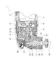
- FIG. 2 It is a side view of the reciprocating power tool of Embodiment 2 which showed the internal structure of the front-end part of a housing.
- FIG. 5 is a cross-sectional view taken along line AA in FIG. 4.
- a reciprocating power tool 1 shown in FIGS. 1 to 3 includes a housing 2 having a circular cross section and extending in the front-rear direction of the reciprocating power tool 1 (the left-right direction in FIGS. 1 and 2).
- a grip 3 (see FIG. 1) for a user to grip is formed on the outer periphery of the housing 2, and a motor 4 (see FIG. 2) is accommodated in the housing 2.
- the housing 2 is provided with a switch 5 that can switch the motor 4 between an on state and an off state.
- a battery mounting portion 6 (see FIG. 3) is provided at the rear end portion of the housing 2.
- a battery pack 7 for supplying power to the motor 4 when the switch 5 is on is detachably mounted on the battery mounting portion 6.
- the reciprocating power tool 1 is an example of the power tool of the present invention.
- a shaft member 10 is coupled to the front of the rotating shaft 8 of the motor 4 in the housing 2 via a coupling member 9.
- the shaft member 10 is supported in a rotatable state in the housing 2 via bearings 12 and 13.
- An eccentric shaft portion 15 is formed at a substantially central portion in the axial direction of the shaft member 10.
- a bearing 16 whose outer ring is arcuate is assembled to the eccentric shaft portion 15 in an exterior state.
- the spindle 17 is supported in the housing 2 via bearings 18 and 19, and the tip of the spindle 17 projects downward from the housing 2.
- Various tip tools having different shapes and applications, such as cutting tools and polishing tools, can be fixed to the tip of the spindle 17 with bolts 20 (see FIG. 2).
- the spindle 17 is an example of the output shaft of the present invention.
- a link member 21 is supported in the housing 2 between the shaft member 10 and the spindle 17.
- the link member 21 includes a pair of engaging portions (not shown) and arm portions 23.
- the pair of engaging portions are arranged in parallel with each other outside the shaft member 10.
- a bearing 16 is disposed in a space sandwiched between the engaging portions.
- the arm portion 23 protrudes from the main body of the link member 21 toward the spindle 17, and a spindle positioning hole 24 is formed in the arm portion 23.
- a spindle 17 is press-fitted into the spindle positioning hole 24.
- a housing recess 25 is formed on the upper front side of the housing 2 so as to be inclined downward and open downward toward the front side of the housing 2.
- the housing recess 25 is disposed behind the front end face 26 of the housing 2 in the front-rear direction of the housing 2.
- LED27 is arrange
- the LED 27 is electrically connected to the battery pack 7 via a lead wire (not shown), and can emit light by operating a switch that controls energization and de-energization of the LED 27.
- the LED 27 is an example of an illuminating body of the present invention.
- disconnects the pillar material standingly installed on the floor surface in the dark place is demonstrated as an example using the reciprocating power tool 1.
- the user drives the motor 4 by turning on the switch 5 while grasping the grip portion 3.
- the user turns on a switch that controls energization of the LED 27 to cause the LED 27 to emit light.
- the rotating shaft 8 of the motor 4 rotates
- the bearing 16 assembled to the eccentric shaft portion 15 rotates eccentrically around the shaft member 10.
- the link member 21 repeats the movement in which the bearing 16 abuts only in the left-right direction with respect to the engaging portion of the link member 21, so that the link member 21 can be Reciprocates left and right in front view.
- the spindle 17 and the cutting tool fixed to the spindle 17 reciprocate left and right around the axis of the spindle 17.
- the column material is cut by pressing a cutting tool that reciprocates while maintaining the spindle 17 in a state orthogonal to the floor surface.
- the light emitted from the LED 27 passes through the opening of the housing recess 25 and is irradiated obliquely forward and downward from the front upper side of the housing 2, so that the cutting tool protruding forward from the spindle 17 is irradiated with light. Has been. Therefore, even in a dark place, the pillar material can be cut while visually confirming the cutting tool with the light emitted by the LED 27.
- the cutting tool can be used up to the cutting limit length with respect to the column material when the column material is cut. Therefore, even if LED27 is arrange
- the LED 27 can irradiate the cutting tool fixed to the tip of the spindle 17 with light. As a result, the cutting tool illuminated by the LED 27 can be visually recognized even in a dark place, and the workability at the time of cutting the column material by the reciprocating power tool 1 is improved.
- the cutting tool when cutting column material, the cutting tool can be used up to the cut limit length for the column material. Therefore, the LED 27 does not hinder the column material cutting work by the cutting tool.
- FIGS. 4 to 6 A second embodiment of the present invention will be described with reference to FIGS.
- the same components as those of the first embodiment are denoted by the same reference numerals, and the description thereof is omitted.
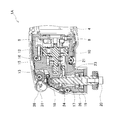
- a rotation operation unit 30 (see FIG. 6) that can be manually rotated in the vertical direction is provided on the upper front side of the housing 2.
- the rotation operation unit 30 is a plate-like member having a fan shape that can be rotated in the vertical direction, and a plurality of operation protrusions 34 (see FIGS. 4 and 6) are formed on the outer surface.
- a housing recess 36 (see FIG.
- the LED unit 31 in which the LEDs are arranged is formed on the front upper side of the housing 2 with the front side opened.
- the LED unit 31 is housed in a state where the light emitting portion of the LED faces the opening.
- the LED unit 31 is assembled with a shaft member 37 extending in the left-right direction (left-right direction in FIG. 7) of the reciprocating power tool 1 ⁇ / b> A.
- the attached mounting portion 35 is fitted.
- the operation of the reciprocating electric tool 1A will be described.
- the user rotates the rotation operation unit 30 in the vertical direction while touching the operation protrusion 34,
- the LED arranged in the LED unit 31 with the shaft member 37 as the rotation center can be moved to an arbitrary position in the vertical direction. Therefore, by fixing different types of tip tools to the spindle 17, even when the projection length of the tip tool from the spindle 17 is different, the tip tool can be irradiated with the light emitted from the LED by the rotation operation of the rotary operation unit 30. Become. Therefore, it is possible to cut the pillar material while visually confirming the tip tool with light emitted from the LED even in a dark place.
- the LED disposed in the LED unit 31 can be moved to an arbitrary position in the vertical direction by the rotation operation unit 30. In connection with this, light can be irradiated in arbitrary directions with LED.
- the present invention is not limited to the embodiment described above, and can be implemented by appropriately changing a part of the configuration without departing from the spirit of the invention.
- a light bulb may be used instead of the LED.
- this invention is a reciprocating power tool of AC drive type, rechargeable Or an AC drive type angle electric tool.
Landscapes
- Engineering & Computer Science (AREA)
- Mechanical Engineering (AREA)
- Physics & Mathematics (AREA)
- Optics & Photonics (AREA)
- Portable Power Tools In General (AREA)
- Details Of Spanners, Wrenches, And Screw Drivers And Accessories (AREA)
Priority Applications (3)
| Application Number | Priority Date | Filing Date | Title |
|---|---|---|---|
| US14/234,443 US20140190716A1 (en) | 2011-09-12 | 2012-07-10 | Electric power tool |
| CN201280043899.4A CN103781598A (zh) | 2011-09-12 | 2012-07-10 | 电动工具 |
| EP12832556.0A EP2756926A4 (en) | 2011-09-12 | 2012-07-10 | POWER TOOL |
Applications Claiming Priority (2)
| Application Number | Priority Date | Filing Date | Title |
|---|---|---|---|
| JP2011-198662 | 2011-09-12 | ||
| JP2011198662A JP2013059820A (ja) | 2011-09-12 | 2011-09-12 | 電動工具 |
Publications (1)
| Publication Number | Publication Date |
|---|---|
| WO2013038789A1 true WO2013038789A1 (ja) | 2013-03-21 |
Family
ID=47883031
Family Applications (1)
| Application Number | Title | Priority Date | Filing Date |
|---|---|---|---|
| PCT/JP2012/067566 Ceased WO2013038789A1 (ja) | 2011-09-12 | 2012-07-10 | 電動工具 |
Country Status (5)
| Country | Link |
|---|---|
| US (1) | US20140190716A1 (https=) |
| EP (1) | EP2756926A4 (https=) |
| JP (1) | JP2013059820A (https=) |
| CN (1) | CN103781598A (https=) |
| WO (1) | WO2013038789A1 (https=) |
Cited By (1)
| Publication number | Priority date | Publication date | Assignee | Title |
|---|---|---|---|---|
| JPWO2023234186A1 (https=) * | 2022-05-31 | 2023-12-07 |
Families Citing this family (9)
| Publication number | Priority date | Publication date | Assignee | Title |
|---|---|---|---|---|
| US10883579B2 (en) * | 2013-12-20 | 2021-01-05 | Robert Bosch Tool Corporation | Oscillating mechanism for a power tool |
| DE102014215045A1 (de) * | 2014-07-31 | 2016-02-04 | Robert Bosch Gmbh | Hochleistungshandwerkzeugmaschine |
| DE102014221760A1 (de) * | 2014-10-27 | 2016-04-28 | Robert Bosch Gmbh | Schleifgerät mit mindestens einem ersten Gehäuseteil |
| JP6727828B2 (ja) * | 2016-02-05 | 2020-07-22 | 株式会社マキタ | 動力工具 |
| US11007632B2 (en) | 2017-12-01 | 2021-05-18 | Makita Corporation | Power tool |
| WO2021173431A1 (en) | 2020-02-24 | 2021-09-02 | Milwaukee Electric Tool Corporation | Impact tool |
| CN212553690U (zh) | 2020-06-12 | 2021-02-19 | 米沃奇电动工具公司 | 摆动电动工具 |
| CN212653400U (zh) | 2020-06-12 | 2021-03-05 | 米沃奇电动工具公司 | 具有照明组件的摆动电动工具 |
| TWM638425U (zh) | 2022-02-22 | 2023-03-11 | 鑽全實業股份有限公司 | 電動工具 |
Citations (5)
| Publication number | Priority date | Publication date | Assignee | Title |
|---|---|---|---|---|
| JPS51131984A (en) * | 1975-05-13 | 1976-11-16 | Yagami Kogyo Kk | Grinder |
| JPS6168855U (https=) * | 1984-10-06 | 1986-05-12 | ||
| JPH0317864U (https=) * | 1989-06-30 | 1991-02-21 | ||
| JPH0537452U (ja) * | 1991-10-25 | 1993-05-21 | リヨービ株式会社 | 研磨装置の揺動駆動機構 |
| US7568288B2 (en) | 2003-08-26 | 2009-08-04 | Credo Technology Corporation | Power hand tool right angle attachment having a light source with a self-generating power supply |
Family Cites Families (26)
| Publication number | Priority date | Publication date | Assignee | Title |
|---|---|---|---|---|
| US2310166A (en) * | 1941-01-24 | 1943-02-02 | Singer Mfg Co | Lighting device for portable electric tools |
| US2517882A (en) * | 1947-08-11 | 1950-08-08 | Johnson Moses | Illuminated hand held motor tool |
| US3393309A (en) * | 1965-10-20 | 1968-07-16 | Rockwell Mfg Co | Power-operated tool |
| GB9415011D0 (en) * | 1994-07-26 | 1994-09-14 | Black & Decker Inc | Improved oscillating hand tool |
| US5445479A (en) * | 1994-08-17 | 1995-08-29 | Hillinger; George | Ergonomically designed, electrically energized hand drill having a housing, longitudinally aligned with a hand, wrist and forearm support |
| JP3017864U (ja) * | 1995-01-10 | 1995-11-07 | 非破壊検査株式会社 | グラインダ用照明装置 |
| US5954458A (en) * | 1998-07-10 | 1999-09-21 | Test Rite Products Corporation | Cordless drill with adjustable light |
| US6565227B1 (en) * | 2001-11-13 | 2003-05-20 | Greg Davis | Method and device for tool alignment |
| DE10254829A1 (de) * | 2002-11-25 | 2004-06-03 | Robert Bosch Gmbh | Elektrohandwerkzeugmaschine |
| US20050058890A1 (en) * | 2003-09-15 | 2005-03-17 | Kenneth Brazell | Removable battery pack for a portable electric power tool |
| DE10356068A1 (de) * | 2003-12-01 | 2005-06-23 | Robert Bosch Gmbh | Handwerkzeugmaschine |
| CN1709648A (zh) * | 2004-06-16 | 2005-12-21 | 财团法人工业技术研究院 | 气动/液动工具的照明设备 |
| DE102005039291A1 (de) * | 2005-08-19 | 2007-02-22 | Robert Bosch Gmbh | Handschleifmaschine |
| DE102007018466A1 (de) * | 2007-04-19 | 2008-10-23 | Robert Bosch Gmbh | Motorisch angetriebene Werkzeugmaschine |
| JP4977533B2 (ja) * | 2007-06-07 | 2012-07-18 | 株式会社マキタ | 可搬型電動工具 |
| JP5088614B2 (ja) * | 2007-09-28 | 2012-12-05 | 日立工機株式会社 | 電動工具 |
| DE102007061741A1 (de) * | 2007-12-20 | 2009-06-25 | Robert Bosch Gmbh | Werkzeugmaschine mit einer Arbeitsfeldbeleuchtung |
| DE102008001479A1 (de) * | 2008-04-30 | 2009-11-05 | Robert Bosch Gmbh | Elektrowerkzeugmaschine |
| JP2010030024A (ja) * | 2008-07-31 | 2010-02-12 | Makita Corp | 電気機器 |
| CN201295872Y (zh) * | 2008-11-12 | 2009-08-26 | 南京德朔实业有限公司 | 砂光机 |
| DE202009001437U1 (de) * | 2009-01-29 | 2010-07-01 | C. & E. Fein Gmbh | Kraftgetriebenes Handwerkzeug |
| DE102010002185A1 (de) * | 2010-02-22 | 2011-08-25 | Robert Bosch GmbH, 70469 | Werkzeugmaschine mit aktivem elektrischem Generator zur Stromerzeugung |
| DE102010002182A1 (de) * | 2010-02-22 | 2011-08-25 | Robert Bosch GmbH, 70469 | Werkzeugmaschine mit elektrischem Generator zur passiven Stromerzeugung |
| DE102010046629A1 (de) * | 2010-09-17 | 2012-03-22 | C. & E. Fein Gmbh | Handwerkzeug |
| AU2012245536A1 (en) * | 2011-04-21 | 2013-11-07 | Infusion Brands, Inc. | Dual oscillating multi-tool saw |
| DE102012224448A1 (de) * | 2012-12-27 | 2014-07-03 | Robert Bosch Gmbh | Handwerkzeugmaschinenbeleuchtungsvorrichtung |
-
2011
- 2011-09-12 JP JP2011198662A patent/JP2013059820A/ja active Pending
-
2012
- 2012-07-10 EP EP12832556.0A patent/EP2756926A4/en not_active Withdrawn
- 2012-07-10 CN CN201280043899.4A patent/CN103781598A/zh active Pending
- 2012-07-10 US US14/234,443 patent/US20140190716A1/en not_active Abandoned
- 2012-07-10 WO PCT/JP2012/067566 patent/WO2013038789A1/ja not_active Ceased
Patent Citations (5)
| Publication number | Priority date | Publication date | Assignee | Title |
|---|---|---|---|---|
| JPS51131984A (en) * | 1975-05-13 | 1976-11-16 | Yagami Kogyo Kk | Grinder |
| JPS6168855U (https=) * | 1984-10-06 | 1986-05-12 | ||
| JPH0317864U (https=) * | 1989-06-30 | 1991-02-21 | ||
| JPH0537452U (ja) * | 1991-10-25 | 1993-05-21 | リヨービ株式会社 | 研磨装置の揺動駆動機構 |
| US7568288B2 (en) | 2003-08-26 | 2009-08-04 | Credo Technology Corporation | Power hand tool right angle attachment having a light source with a self-generating power supply |
Non-Patent Citations (1)
| Title |
|---|
| See also references of EP2756926A4 |
Cited By (2)
| Publication number | Priority date | Publication date | Assignee | Title |
|---|---|---|---|---|
| JPWO2023234186A1 (https=) * | 2022-05-31 | 2023-12-07 | ||
| JP7832546B2 (ja) | 2022-05-31 | 2026-03-18 | 工機ホールディングス株式会社 | 作業機 |
Also Published As
| Publication number | Publication date |
|---|---|
| EP2756926A1 (en) | 2014-07-23 |
| JP2013059820A (ja) | 2013-04-04 |
| US20140190716A1 (en) | 2014-07-10 |
| EP2756926A4 (en) | 2016-04-27 |
| CN103781598A (zh) | 2014-05-07 |
Similar Documents
| Publication | Publication Date | Title |
|---|---|---|
| WO2013038789A1 (ja) | 電動工具 | |
| US10821595B2 (en) | Power tool | |
| US6918331B2 (en) | Lighted cutting tools | |
| CN203566655U (zh) | 便携式工具 | |
| US10286462B2 (en) | Cutting machine | |
| JP6863704B2 (ja) | 打撃工具 | |
| CN103158119B (zh) | 电动工具 | |
| EP3386683B1 (en) | Rotary power tool lighting system | |
| CN115570540B (zh) | 动力工具 | |
| JP4936220B2 (ja) | 電動工具 | |
| JP2018008356A (ja) | 動力工具 | |
| JP2014198354A (ja) | 電動工具 | |
| JP5053791B2 (ja) | 打撃工具 | |
| JP5280422B2 (ja) | 切断機 | |
| CN108068067A (zh) | 动力工具 | |
| JP2013031906A (ja) | 往復回転式電動工具 | |
| CN1915594A (zh) | 手持式磨削机 | |
| CN211565466U (zh) | 带式打磨机 | |
| JP2018043372A (ja) | 携帯用加工機 | |
| JP4789617B2 (ja) | 電動工具 | |
| JP5007934B2 (ja) | 電動工具 | |
| CN221390897U (zh) | 多功能工具 | |
| JP5769017B2 (ja) | 電動工具 | |
| US11938607B2 (en) | Power tool with light emitter | |
| JP2010094782A (ja) | 電動切削研磨工具 |
Legal Events
| Date | Code | Title | Description |
|---|---|---|---|
| 121 | Ep: the epo has been informed by wipo that ep was designated in this application |
Ref document number: 12832556 Country of ref document: EP Kind code of ref document: A1 |
|
| WWE | Wipo information: entry into national phase |
Ref document number: 14234443 Country of ref document: US |
|
| NENP | Non-entry into the national phase |
Ref country code: DE |
|
| WWE | Wipo information: entry into national phase |
Ref document number: 2012832556 Country of ref document: EP |