WO2013031902A1 - 光量調整装置及び光量調整システム - Google Patents
光量調整装置及び光量調整システム Download PDFInfo
- Publication number
- WO2013031902A1 WO2013031902A1 PCT/JP2012/072026 JP2012072026W WO2013031902A1 WO 2013031902 A1 WO2013031902 A1 WO 2013031902A1 JP 2012072026 W JP2012072026 W JP 2012072026W WO 2013031902 A1 WO2013031902 A1 WO 2013031902A1
- Authority
- WO
- WIPO (PCT)
- Prior art keywords
- light
- power generation
- shielding member
- solar cell
- incident
- Prior art date
- Legal status (The legal status is an assumption and is not a legal conclusion. Google has not performed a legal analysis and makes no representation as to the accuracy of the status listed.)
- Ceased
Links
Images









Classifications
-
- H—ELECTRICITY
- H02—GENERATION; CONVERSION OR DISTRIBUTION OF ELECTRIC POWER
- H02S—GENERATION OF ELECTRIC POWER BY CONVERSION OF INFRARED RADIATION, VISIBLE LIGHT OR ULTRAVIOLET LIGHT, e.g. USING PHOTOVOLTAIC [PV] MODULES
- H02S20/00—Supporting structures for PV modules
-
- H—ELECTRICITY
- H02—GENERATION; CONVERSION OR DISTRIBUTION OF ELECTRIC POWER
- H02S—GENERATION OF ELECTRIC POWER BY CONVERSION OF INFRARED RADIATION, VISIBLE LIGHT OR ULTRAVIOLET LIGHT, e.g. USING PHOTOVOLTAIC [PV] MODULES
- H02S20/00—Supporting structures for PV modules
- H02S20/30—Supporting structures being movable or adjustable, e.g. for angle adjustment
-
- H—ELECTRICITY
- H10—SEMICONDUCTOR DEVICES; ELECTRIC SOLID-STATE DEVICES NOT OTHERWISE PROVIDED FOR
- H10F—INORGANIC SEMICONDUCTOR DEVICES SENSITIVE TO INFRARED RADIATION, LIGHT, ELECTROMAGNETIC RADIATION OF SHORTER WAVELENGTH OR CORPUSCULAR RADIATION
- H10F77/00—Constructional details of devices covered by this subclass
- H10F77/40—Optical elements or arrangements
- H10F77/42—Optical elements or arrangements directly associated or integrated with photovoltaic cells, e.g. light-reflecting means or light-concentrating means
- H10F77/488—Reflecting light-concentrating means, e.g. parabolic mirrors or concentrators using total internal reflection
-
- Y—GENERAL TAGGING OF NEW TECHNOLOGICAL DEVELOPMENTS; GENERAL TAGGING OF CROSS-SECTIONAL TECHNOLOGIES SPANNING OVER SEVERAL SECTIONS OF THE IPC; TECHNICAL SUBJECTS COVERED BY FORMER USPC CROSS-REFERENCE ART COLLECTIONS [XRACs] AND DIGESTS
- Y02—TECHNOLOGIES OR APPLICATIONS FOR MITIGATION OR ADAPTATION AGAINST CLIMATE CHANGE
- Y02E—REDUCTION OF GREENHOUSE GAS [GHG] EMISSIONS, RELATED TO ENERGY GENERATION, TRANSMISSION OR DISTRIBUTION
- Y02E10/00—Energy generation through renewable energy sources
- Y02E10/50—Photovoltaic [PV] energy
- Y02E10/52—PV systems with concentrators
Definitions
- the present invention relates to a light amount adjusting device and a light amount adjusting system for adjusting the amount of transmitted light.
- Plant cultivation in greenhouses is generally done. Thus, when cultivating a plant in a greenhouse, it is important to manage the temperature and the amount of incident light in the greenhouse.
- the temperature in the greenhouse can be maintained at a temperature generally suitable for plant cultivation (about 20 ° C to 25 ° C) by heating with sunlight.
- a temperature generally suitable for plant cultivation about 20 ° C to 25 ° C
- a method of cooling a greenhouse with an air conditioner air conditioner
- a device such as a method of reducing the incidence rate of sunlight into the greenhouse using a curtain has been devised.
- the method of cooling with an air conditioner requires expensive running costs (electrical charges, etc.).
- the method of reducing the incidence of infrared rays into the greenhouse using an infrared cut film is effective in preventing excessive heating in the summer, but is not necessary if you want to warm the greenhouse in the winter. It becomes.
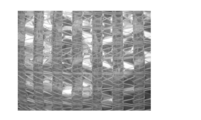
- the reflective sheet shown in FIG. 23 is configured by, for example, 50% knitting of an aluminum sheet. For this reason, although excessive warming of a greenhouse can be prevented, since the transmittance
- Patent Document 1 discloses a solar cell panel device in which a solar cell panel is arranged to be rotatable around an axis.
- the amount of light collected into the building is adjusted by adjusting the angle of the solar cell panel.
- FIG. 24 is a plan view showing a configuration of a conventional solar panel device.
- the solar cell panel device 900 includes a rotating shaft 901 extending in one direction and a solar cell panel 902 that is rotatably arranged with the rotating shaft 901 as a rotation center.
- the amount of sunlight incident on the building can be adjusted by rotating the solar cell panel 902 around the rotation axis 901 and adjusting the angle.
- the desired temperature in the greenhouse and the desired amount of incident light vary depending on the type of plant cultivated, the time zone, the season, and the like. For this reason, it is necessary to individually adjust the amount of light incident on the greenhouse and the temperature in the greenhouse.
- the present invention has been made to solve the above-mentioned problems, and its purpose is to adjust the amount of transmitted light and the amount of heat rays with a simple configuration.
- a light amount adjusting device of the present invention is a light amount adjusting device that adjusts the amount of transmitted light by blocking incident light, and includes a first rotating shaft extending in one direction, A light-shielding member that is rotatable about the first rotation axis, and that changes a light-shielding amount of the incident light corresponding to the rotational position; and the light-shielding member corresponding to the rotational position of the light-shielding member.
- a first heat ray shielding member that changes an angle with respect to the member, and an angle defining member that defines a range of angles formed by the light shielding member and the first heat ray shielding member.
- the light shielding member is arranged so as to be rotatable about the first rotation axis extending in one direction, and changes the amount of light incident on the light corresponding to the rotational position. For this reason, by controlling the rotational position of the light shielding member, the light shielding amount of incident light shielded by the light shielding member can be adjusted. As a result, the amount of transmitted light from the device can be adjusted.
- the angle of the first heat ray shielding member with respect to the light shielding member changes corresponding to the rotational position of the light shielding member.
- the angle of the first heat ray shielding member with respect to the light shielding member can be adjusted by controlling the rotational position of the light shielding member with respect to the first rotation axis.
- the light quantity adjusting device can be obtained with a simple configuration.
- the angle defining member defines a range of angles formed by the light shielding member and the first heat ray shielding member. Thereby, the position of the first heat ray shielding member with respect to the first rotating shaft can be adjusted. Thereby, the quantity of the heat ray which injects into the said 1st heat ray shielding member can be adjusted.
- the amount of light and the amount of heat rays can be adjusted with a simple configuration.
- the light amount adjusting device of the present invention is a light amount adjusting device that adjusts the amount of transmitted light by blocking incident light, and is centered on a first rotating shaft extending in one direction and the first rotating shaft.
- a light-shielding member that is arranged so as to be rotatable, and that changes a light-shielding amount of the incident light corresponding to a rotational position; and a first angle that changes an angle relative to the light-shielding member corresponding to a rotational position of the light-shielding member.
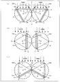
- (A) is a cross-sectional view of a power generation device configured to generate power
- (b) is a cross-sectional view of a power generation device configured to perform daylighting and heating
- (c) is a power generation device configured to perform daylighting and shielding heat rays.
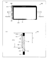
- It is sectional drawing. It is a perspective view showing the structure of the frame which comprises the electric power generating apparatus of 1st Embodiment. It is a perspective view showing the appearance of the power generator of a 1st embodiment. It is sectional drawing to which the area
- (A) is a figure showing the case where a plurality of power generators 20 are made into power generation form (1)
- (b) is the figure showing the case where a plurality of power generators are made into lighting form (2)
- (c) These are figures showing the case where a some electric power generating apparatus is made into the lighting form (3).
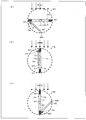
- (A) is a figure showing the power generation form (1) when sunlight enters from an oblique direction
- (b) shows the daylighting form (2) when sunlight enters from an oblique direction.
- (c) is a figure showing the lighting form (3) when sunlight injects from the diagonal direction.
- FIG. 1 It is a block diagram showing the structure of the electric power generation system of 1st Embodiment. It is a flowchart showing the process of the electric power generation system of 1st Embodiment. It is a figure showing the structure of the said electric power generation system modification.
- (A) is a figure which shows power generation form (4)
- (b) is a figure which shows power generation form (5).
- FIG. 1 It is a side view showing the structure of the electric power generating apparatus concerning 4th Embodiment
- (a) is a side view of the electric power generating apparatus of the form which produces electric power
- (b) is the side view of the electric power generating apparatus of the form which performs lighting and heating
- (C) is a side view of a power generation device in a form that is daylighting and shields heat rays.
- (A) is a perspective view showing the structure of the electric power generating apparatus concerning 5th Embodiment
- (b) is a side view of (a). It is a side view showing the composition of the power generator concerning a 5th embodiment.
- (A) is a side view of the power generator of the form which generates power
- (b) is the side view of the power generator of the form which performs lighting and heating
- (C) is a side view of a power generation device in a form that is daylighting and shields heat rays. It is a top view showing the reflective sheet
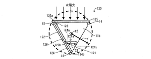
- the power generation device 20 is, for example, for placement on the ceiling of a greenhouse for plant cultivation or in the vicinity of the ceiling. As will be described later, the power generation device 20 rotates about the rotation shaft 12 as a center of rotation, so that (1) power generation and light incident on the greenhouse are blocked, and (2) lighting in the greenhouse and heating of the greenhouse. (3) A power generation device that can take at least three forms of lighting to the greenhouse and shielding heat rays incident on the greenhouse.
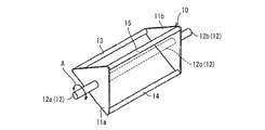
- FIG. 2 is a perspective view illustrating the configuration of the frame body 10 constituting the power generation device 20. First, the structure of the frame 10 which comprises the electric power generating apparatus 20 is demonstrated using FIG.
- the frame body 10 is a frame portion constituting the power generation device 20.
- the frame 10 includes three beam members 13, 14, 15, two support plates 11 a, 11 b, and rotating shafts (first rotating shafts) 12 a, 12 b.
- the frame body 10 is configured to have a triangular prism shape by the beam members 13, 14, 15 and the support plates 11 a, 11 b.
- the support plates 11a and 11b each have a triangular shape and are arranged in parallel to each other.
- Each of the support plates 11a and 11b is a bottom surface of the frame body 10 having a triangular prism shape.
- the beam members 13, 14, and 15 are each configured to extend in one direction, and are arranged in parallel to each other.
- the beam members 13, 14, 15 are respectively arranged at positions where the frame body 10 is formed as a triangular prism shape.
- the support plate 11a is disposed at one end of each of the beam members 13, 14, and 15, and the support plate 11b is disposed at the other end of each of the beam members 13, 14, and 15 on the opposite side.
- Each of the beam members 13, 14, and 15 is disposed so as to connect the apex portions of the support plate 11 a and the support plate 11 b that face each other.
- the distance between the support plate 11a and the support plate 11b is defined by the beam members 13, 14, and 15.
- Cylindrical rotating shafts 12a and 12b extending in the direction parallel to the beam members 13, 14, and 15 are arranged on the outer surfaces of the support plates 11a and 11b (surfaces opposite to the opposing surfaces). Has been.
- the rotary shafts 12a and 12b support the power generation device 20 when the power generation device 20 is attached to the greenhouse, and can also be referred to as support shafts.
- the rotation shafts 12a and 12b which are the support shafts, are arranged on the outer surfaces of the support plates 11a and 11b, respectively, and are not arranged in the regions where the support plates 11a and 11b are opposed to each other. That is, the rotation shaft 12a is disposed on the outer surface of the support plate 11a, and the rotation shaft 12b is disposed on the outer surface of the support plate 11b.
- rotating shaft 12a and the rotating shaft 12b when the rotating shaft 12a and the rotating shaft 12b are extended, the virtual rotating shaft between the support plate 11a and the supporting plate 11b is referred to as a rotating shaft (first rotating shaft) 12c. Called.
- Rotating shafts 12a, 12b, and 12c extending in one direction are rotational directions around the rotating shafts 12a, 12b, and 12c (the direction of arrow A shown in FIG. 2) when the power generator 20 is attached to a greenhouse or the like. This is a rotation shaft for rotating the power generation device 20.
- the rotary shafts 12 a, 12 b, and 12 c are arranged at the centers of the beam member 13, the beam member 14, and the beam member 15.
- the rotation shaft 12a, the rotation shaft 12b, and the rotation shaft 12c are referred to as the rotation shaft (first shaft) when it is not distinguished whether they are formed on the outer surface or the inner surface of the support plates 11a and 11b. 1 rotation axis) 12.
- FIG. 1A to 1B (Configuration of power generator 20) Next, the configuration of the power generation device 20 will be described with reference to FIGS. 1A to 1B, FIGS. 3, 4, and 5.
- FIG. 1A to 1B (Configuration of power generator 20) Next, the configuration of the power generation device 20 will be described with reference to FIGS. 1A to 1B, FIGS. 3, 4, and 5.
- FIG. 1A to 1B (Configuration of power generator 20)
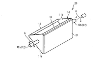
- FIG. 3 is a perspective view showing the appearance of the power generation device (light quantity adjustment device) 20.
- the power generation device 20 includes a frame 10, a solar cell (light shielding member, solar cell panel) 21, a plate 22 (not shown in FIG. 3), and a hinge 23 (not shown in FIG. 3). As shown).
- the solar cell 21 is attached to the frame 10 so as to cover a surface of the frame 10 formed by the beam member 14, the beam member 15, one side of the support plate 11a, and one side of the support plate 11b. .
- the solar cell 21 is disposed so as to be rotatable in a direction (the direction of arrow A in FIG. 3) with the rotation shaft 12 as the rotation center.
- the solar cell 21 has a shape that changes the light shielding amount and power generation amount of incident light corresponding to the rotational position. In this embodiment, it is a plate-like rectangular shape.
- the direction in which the beam members 14 and 15 extend is the longitudinal direction of the solar cell 21.
- the direction perpendicular to the beam members 14 and 15 (that is, the direction in which one side of the support plates 11 a and 11 b extends) is the short direction of the solar cell 21 perpendicular to the longitudinal direction of the solar cell 21.
- the solar cell 21 is not limited to a rectangular shape, as long as it can block incident sunlight, generate electric power, and change the amount of incident light blocked according to the rotational position with respect to the rotating shaft 12. , A square shape, a polygonal shape, a circular shape, or other shapes.
- the solar cell 21 shields light incident on the greenhouse 35 and generates a current corresponding to the amount of incident light on the light receiving surface of the solar cell 21 so that the generated current can be externally output.
- the power generation device 20 may include a light shielding member that does not have a power generation function and blocks sunlight, instead of the solar cell 21.
- FIG. 1A is a cross-sectional view of the power generation apparatus 20 configured to generate power
- FIG. 1B is a cross-sectional view of the power generation apparatus 20 configured to perform daylighting and heating
- FIG. It is sectional drawing of the electric power generating apparatus 20 of a form.
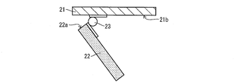
- FIG. 4 is an enlarged cross-sectional view of region B in FIG.
- FIG. 5 is an enlarged perspective view of a region B in FIG.
- the surface of the solar cell 21 that faces the beam 13 is a back surface (one surface) 21b, and the surface opposite to the back surface 21b is incident on sunlight or the like.
- This is a light receiving surface 21a for receiving light.
- the plate-like solar cell 21 is disposed so as to be rotatable about the rotating shaft 12 extending in one direction. For this reason, the light quantity of the incident light shielded by the solar cell 21 can be adjusted by controlling the rotational position of the solar cell 21 with respect to the rotating shaft 12. As a result, the amount of transmitted light from the power generation device 20 can be adjusted, and the amount of power generated by the solar cell 21 can also be adjusted.
- the beam members 14 and 15 and the support plates 11a and 11b are disposed on the back surface 21b of the solar cell 21, and the plate (first heat ray shielding member) 22 and the hinge (second rotation shaft) 23 are also disposed. .
- the hinge 23 is arranged in the vicinity of the beam member 15 on the back surface 21 b of the solar cell 21.
- the hinge 23 is arranged on the back surface 21b of the solar cell 21, and is arranged extending in one direction.
- the hinge 23 is arranged extending in the longitudinal direction of the solar cell 21. That is, the hinge 23 is arranged so as to be parallel to the rotating shaft 12 and the beam members 13, 14, 15.
- a hinge 23 connects the back surface 21 b of the solar cell 21 and one end 22 a of the plate 22.
- the hinge 23 a general structure that is used by screwing the material may be used.
- the hinge 23 may be fixed to the back surface 21b of the solar cell 21 and the plate 22 with an adhesive depending on the back surface 21b of the solar cell 21 generally made of glass or the material of the plate 22.
- the fixing method of the hinge 23, the back surface 21b of the solar cell 21, and the plate 22 is not limited to this.
- the material of the hinge 23 is preferably a light transmissive plastic or the like, but is not limited thereto.
- the hinge 23 should just be distribute
- the plate 22 is a plate having an infrared cut function.
- the plate 22 shields infrared rays (heat rays) out of incident light such as sunlight and transmits visible light.
- the plate 22 has one end 22 a connected to the hinge 23. As shown in FIGS. 1A to 1C, the other end 22b that forms a pair with one end 22a of the plate 22 (opposite the end 22a) is a back surface 21b of the solar cell 21. Not connected to.
- the angle of the plate 22 with respect to the solar cell 21 can be adjusted by gravity.
- the angle of the plate 22 with respect to the solar cell 21 changes corresponding to the rotational position of the solar cell 21 with respect to the rotating shaft 12. For this reason, the angle of the plate 22 with respect to the solar cell 21 can be adjusted by controlling the rotational position of the solar cell 21 with respect to the rotating shaft 12.
- the power generation device 20 can be obtained with a simple configuration.
- the plate 22 has a rectangular shape, and the direction in which the end portions 22a and 22b extend is the longitudinal direction. That is, the longitudinal direction of the plate 22 and the longitudinal direction of the solar cell 21 are parallel.
- the plate 22 is not limited to a rectangular shape as long as it can shield infrared rays of incident light and transmit visible light, and may be a square shape, a polygonal shape, a circular shape, or other shapes.
- the plate 22 can be configured by attaching a film having an infrared cut function to glass or acrylic, or applying a paint having an infrared cut function.
- the beam member 13 interferes with the plate 22 by contacting the plate 22 whose angle with respect to the solar cell 21 changes, and functions as an angle defining member for defining the range of angles formed by the solar cell 21 and the plate 22.
- the beam member 13 is disposed at a position where the beam member 13 interferes with the plate 22 by contacting with the plate 22 rotating about the hinge 23.
- the beam member 13 is disposed at a position where the end 22b of the plate 22 abuts. That is, the beam member 13 is disposed at a position where a triangular prism shape is formed by the beam member 13 and the solar cell 21.
- the beam member 13 Since the beam member 13 is disposed at a position where it abuts on the plate 22 whose angle with respect to the solar cell 21 changes, it can regulate the range of angles formed by the solar cell 21 and the plate 22 by abutting on the plate 22. it can. That is, the angle of the plate 22 with respect to the solar cell 21 can be maintained. For this reason, the light quantity of the sunlight which permeate
- the contact area is increased and the solar cell of the plate 22 is stably formed.
- the change of the angle with respect to 21 can be stopped. That is, the angle of the plate 22 with respect to the solar cell 21 can be stably maintained.
- the plate 22 is in contact with the beam member 13 so that the maximum angle with respect to the solar cell 21 is defined. Thereby, the position of the plate 22 with respect to the rotating shaft 12 (that is, the angle of the plate 22 with respect to the horizontal plane) can be adjusted.
- the incident angle of the infrared rays incident on the power generation device 20 with respect to the plate 22 can be adjusted, the amount of infrared rays transmitted from the power generation device 20 can be adjusted.
- the triangular prism shape is formed by the beam member 13 and the solar cell 21, so that one end 22 a is connected to the hinge 23 and the other end 22 b is in contact with the beam 13 to reduce the area of the plate 22.
- the area can be approximately the same as the area of the battery 21. For this reason, it is easy to adjust the amount of light and the amount of heat rays. For this reason, the highly versatile power generator 20 can be obtained.
- the shape of the power generation device 20 is not limited to the triangular prism shape, and may be other shapes such as a polygonal column of a quadrangular column or more.
- a linear member such as a string or a chain connecting the solar cell 21 and the end 22 b of the plate 22 may be provided, and the linear member may be used as the angle defining member. Good.
- the incident light with respect to the power generation device 20 is sunlight
- the incident direction of the sunlight with respect to the power generation device 20 is the vertical direction. It is assumed that the direction is from above to below.
- FIG. 1 is a figure showing the electric power generating apparatus 20 of the form which shields the incident light to the electric power generating apparatus 20 and electric power generation.
- This form of the power generation device 20 is referred to as “first form” or “power generation form (1)”.
- the first form is a form for generating power and shielding the greenhouse.
- the rotational position of the power generation device 20 in the first form is referred to as a “first position”.
- the first position is a power generator for maximizing the amount of sunlight incident on the light receiving surface 21a of the solar cell 21 and minimizing the amount of sunlight incident on the plate 22 (ie, the amount of incident infrared rays). 20 rotational positions.
- the first position is the rotational position of the power generation device 20 for maximizing the amount of sunlight that is shielded by the power generation device 20.
- the first position is the direction in which the light receiving surface 21a of the solar cell 21 is perpendicular to the vertical direction (that is, the horizontal direction), and the light receiving surface 21a from the back surface 21b of the solar cell 21. Is a position arranged on the upper side in the vertical direction.
- the first position is a position where the light receiving surface 21a of the solar cell 21 and the vertical direction are non-parallel, and the light receiving surface 21a is arranged above the back surface 21b of the solar cell 21 in the vertical direction.
- the light receiving surface 21a of the solar cell 21 can be adjusted with respect to the incident direction of sunlight.
- the light receiving surface 21a may be positioned on the side where sunlight enters from the back surface 21b of the solar cell 21 (using (a) to (c) of FIG. 7). Will be described later).
- the first position is the side where the light receiving surface 21a of the solar cell 21 and the incident direction of sunlight are non-parallel, and the light receiving surface 21a is incident on the light receiving surface 21a from the back surface 21b of the solar cell 21. It is good also as a position arranged to.
- the solar cell 21 can receive sunlight to the maximum extent by the light receiving surface 21a and also can shield the light to the maximum extent. For this reason, by setting the power generation device 20 in the first form, the sunlight incident on the greenhouse can be shielded to the maximum by the solar cell 21 and the power can be generated to the maximum by the light receiving surface 21a of the solar cell 21.
- the end 22 b on the side not connected to the back surface 21 b by the hinge 23 is lowered downward due to gravity and is in contact with the beam member 13.
- the beam member 13 serves as a stopper for the plate 22 so that the end 22b does not protrude from the rotation radius of the power generation device 20 around the rotation shaft 12 (arrow r in FIG. 1A).
- (B) of FIG. 1 is the power generator 20 of the form which permeate
- This form is referred to as “second form” or “lighting form (2)”.
- the second form is a form for daylighting the greenhouse and heating the greenhouse (that is, making infrared rays enter the greenhouse).
- the rotational position of the power generation device 20 in the second form is referred to as a “second position”.
- the second position is a power generator for minimizing the amount of sunlight incident on the light receiving surface 21a of the solar cell 21 and also minimizing the amount of sunlight incident on the plate 22 (that is, the amount of incident infrared rays). 20 rotational positions.
- the second position is the rotational position of the power generation device 20 for maximizing the amount of sunlight transmitted through the power generation device 20 as it is.
- the second position is that the light receiving surface 21a and the plate 22 of the solar cell 21 are parallel to the vertical direction (that is, the vertical direction with respect to the horizontal direction), and the hinge.
- Reference numeral 23 denotes a position arranged above the rotary shaft 12.
- the light receiving surface 21a of the solar cell 21 and the plate 22 It may be a position arranged in a direction parallel to the incident direction (described later using FIGS. 7A to 7C).
- Rotating the 90 ° power generator 20 clockwise from the first position allows the power generator 20 to be in the second position.
- the power generation device 20 can transmit the maximum amount of sunlight without shielding infrared rays. For this reason, by setting the power generation device 20 in the second form, it is possible to make sunlight enter the greenhouse as much as possible, so that the sunlight can be collected into the greenhouse, and the infrared rays of sunlight are not shielded. Can be warmed.
- (C) of FIG. 1 is the power generator 20 of the form which shields infrared light among the incident light to the power generator 20.
- This form is referred to as “third form” or “lighting form (3)”.
- the third form is a form for daylighting the greenhouse and preventing excessive warming of the greenhouse (ie, cutting infrared rays).
- the rotational position of the power generation device 20 in the third form is referred to as a “third position”.
- the third position is a power generator for minimizing the amount of sunlight incident on the light receiving surface 21a of the solar cell 21 and maximizing the amount of sunlight incident on the plate 22 (ie, the amount of incident infrared rays). 20 rotational positions.
- the third position is a direction in which the light receiving surface 21a of the solar cell 21 is parallel to the vertical direction (that is, a direction perpendicular to the horizontal direction), and the hinge 23 is rotated. It is a position arranged below the shaft 12.
- the light receiving surface 21a of the solar cell 21 has a third position relative to the incident direction of sunlight. And a position where sunlight enters the plate 22 (which will be described later with reference to FIGS. 7A to 7C).
- Rotating the 90 ° power generator 20 counterclockwise from the first position allows the power generator 20 to be in the third position.
- the end 22a of the plate 22 connected to the hinge 23 is arranged below, so that the end 22b not connected to the hinge 23 is connected to the beam member 13. Abut. Thereby, the plane formed by the beam members 14 and 15 is covered with the plate 22.
- the incident light which is sunlight
- the electric power generating apparatus 20 can permeate
- the greenhouse can be lit and the infrared rays of sunlight are shielded, so that excessive warming of the greenhouse can be prevented.
- the adjustment of the amount of light collected into the greenhouse is based on the amount of power generated by the power generation device 20 based on the amount of light received by the light reception sensor when the power generation device 20 is equipped with a light reception sensor or pre-registered data. Executed.
- the power generation system 30 including the power generation device 20 includes one or a plurality of power generation devices 20 arranged on the roof of the greenhouse or in the vicinity of the roof.
- FIG. 6 is a figure showing the case where a plurality of power generators 20 are made into power generation form (1), and (b) is a figure showing the case where a plurality of power generators 20 are made into lighting form (2). (C) is a figure showing the case where the several electric power generating apparatus 20 is made into the lighting form (3).
- the incident direction of sunlight is the direction from the upper side to the lower side in the vertical direction.
- each power generation device 20 can adjust the amount of sunlight incident on the greenhouse by rotating it by a predetermined angle around the rotation shaft 12, and can select the light quality (the presence or absence of infrared rays). It becomes. In addition, it is possible to generate electricity from sunlight that does not need to enter the greenhouse and cover part of the power in the greenhouse.
- the three power generation devices 20 are set to the power generation mode (1). That is, the light receiving surfaces 21a of the solar cells 21 of the three power generation devices 20 are rotated in the sunlight incident direction and until they are perpendicular to the sunlight incident direction.
- sunlight enters the greenhouse through the gap w between the power generation devices 20.
- the amount of sunlight transmitted through the gap w can be estimated as follows.
- (2- ⁇ 3) r of light enters from the gap w. That is, about 26.8% of the total sunlight is incident on the greenhouse, and the remaining 73.2% of the sunlight goes to power generation. In other words, 73.2% of the total sunlight can be shielded.
- the three power generators 20 Is the daylighting mode (2).
- each power generator 20 is rotated 90 ° clockwise from the position shown in FIG. Thereby, sunlight can be made incident into a greenhouse, without cutting infrared rays.
- the three power generators 20 Is the daylighting mode (3).
- each power generator 20 is rotated 90 ° counterclockwise from the position shown in FIG.
- FIG. 7 is a figure showing the electric power generation form (1) when sunlight injects from an oblique direction
- (b) is the daylighting form in case sunlight enters from an oblique direction
- (C) is a figure showing the lighting form (3) in case sunlight injects from an oblique direction.
- the angle of sunlight varies from sunrise to sunset and according to the season.
- the power generation device 20 may be in each of the first to third embodiments.
- the angle formed by the incident direction of sunlight and the solar cell 21 is changed. Can always be constant.
- the solar cell 21 when it is not necessary to enter sunlight into the greenhouse, the solar cell 21 is perpendicular to the incident direction of sunlight that is incident from an angle of 45 ° to the right. Rotate until That is, let the three power generation devices 20 be a power generation mode (1).
- the power generation device 20 is configured such that the light receiving surface 21 a of the solar cell 21 is perpendicular to the incident direction of sunlight, and the light receiving surface 21 a is sunlight from the back surface 21 b of the solar cell 21. Is the first position arranged on the incident side.
- the angle is 45 ° diagonally to the right.
- the solar cell 21 is rotated in such a way that the solar cell 21 is parallel to the incident direction of sunlight incident from the direction and the hinge 23 connecting the solar cell 21 and the plate 22 is above the rotation shaft 12.
- each power generator 20 is rotated 90 ° clockwise from (a) of FIG. Thereby, the three power generation devices 20 are made into the lighting form (2).
- the power generation device 20 is in the second position where the light receiving surface 21a and the plate 22 of the solar cell 21 are arranged in a direction parallel to the incident direction of sunlight.
- the angle is 45 ° diagonally to the right.
- the solar cell 21 is rotated so that the solar cell 21 is parallel to the incident direction of sunlight entering from the direction and the hinge 23 connecting the solar cell 21 and the plate 22 is below the rotary shaft 12.
- the power generation device 20 is configured such that the light receiving surface 21 a of the solar cell 21 is in a direction parallel to the incident direction of sunlight (that is, a direction perpendicular to the horizontal direction), and The third position where sunlight is incident also on the plate 22 is used.
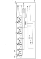
- FIG. 8 is a diagram illustrating a configuration of a power generation system 30 including the power generation device 20.
- the power generation system (light quantity adjustment system) 30 includes a plurality of power generation devices 20, a plurality of switching mechanisms 31, a control device 40, and a sensor unit 32.
- the plurality of power generation devices 20 are arranged in the roof 35a of the greenhouse 35 for plant cultivation or in the vicinity of the roof 35a.
- the power generation system 30 includes eight power generation devices 20.
- each power generator when the length of each power generator 20 in the horizontal direction (that is, the width in the short direction when the solar cells 21 are arranged horizontally) is d and each power generator 20 is in the first position. Let the gap between the 20 solar cells 21 be w.
- the plurality of switching mechanisms 31 can switch each power generation device 20 to any one of the first to third modes by rotating each power generation device 20 to an angle instructed by the control device 40. .
- a plurality of switching mechanisms 31 are arranged for each of the power generators 20.
- the power generation system 30 includes eight switching mechanisms 31 as the plurality of switching mechanisms 31.
- the switching mechanism 31 is connected to the single power generation device 20 and is also connected to the control device 40. And the switching mechanism 31 will change the form of the power generator 20 by rotating the connected power generator 20 based on the acquired instruction signal, if an instruction signal is acquired from the control apparatus 40.
- the sensor unit 32 is a sensor for measuring the temperature and light quantity in the greenhouse 35.
- the sensor unit 32 includes a light amount sensor 33 for measuring the light amount in the greenhouse 35 and a temperature sensor 34 for measuring the temperature in the greenhouse 35.
- the light amount sensor 33 is disposed in the greenhouse 35, measures the amount of light in the greenhouse 35, and uses the measured amount of light in the greenhouse 35 as an actually measured amount of light (x). Is output.
- the light quantity sensor 33 outputs the measured light quantity (x) to the light quantity acquisition section 40b by acquiring the acquisition instruction information of the measured light quantity (x) from the light quantity acquisition section 40b.
- the light amount sensor 33 acquires the actually measured light amount (x) in the greenhouse 35 as a value obtained by dividing the integrated light amount in a certain time by the time.
- the present invention is not limited to this, and the light amount sensor 33 may acquire the actually measured light amount (x) as an instantaneous value obtained by instantaneously measuring the light amount in the greenhouse 35.
- a plurality of light quantity sensors 33 are arranged in the greenhouse 35, acquire the actual measurement light quantity (x) as an average value of the plurality of light quantity sensors 33, and output the acquired actual measurement light quantity (x) to the light quantity acquisition unit 40b. Is preferred.
- the present invention is not limited to this, and only one light amount sensor 33 is disposed in the greenhouse 35, and the light amount measured by the single light amount sensor 33 is output to the light amount acquisition unit 40b as the actually measured light amount (x). May be.
- the temperature sensor 34 is arranged in the greenhouse 35, measures the temperature in the greenhouse 35, and uses the measured temperature in the greenhouse 35 as an actual measurement temperature (y), a temperature acquisition unit 40f (described later) of the control device 40. Is output.
- the temperature sensor 34 obtains the measured temperature (y) from the light amount comparison unit 40c (described later) or the form switching instruction unit 40e (described later) of the control device 40, thereby acquiring the measured temperature (y). Output to the acquisition unit 40f.
- the temperature sensor 34 acquires the actually measured temperature (y) in the greenhouse 35 as a value obtained by dividing the accumulated temperature in a certain time by the time.
- the present invention is not limited to this, and the temperature sensor 34 may acquire the actually measured temperature (y) as an instantaneous value obtained by instantaneously measuring the temperature in the greenhouse 35.
- a plurality of temperature sensors 34 are arranged in the greenhouse 35, acquire the actual temperature (y) as an average value of the plurality of temperature sensors 34, and output the acquired actual temperature (y) to the temperature acquisition unit 40f. Is preferred.
- the present invention is not limited to this, and only one temperature sensor 34 is arranged in the greenhouse 35, and the temperature measured by the single temperature sensor 34 is output to the temperature acquisition unit 40f as the actual temperature (y). May be.
- the power generation system 30 sets the form to be set for each power generation device 20, the light amount sensor 33 and the temperature sensor 34 installed in the greenhouse 35, and pre-registered data (when and what temperature and light amount are desired). Thus, the setting is made according to a flowchart described later.
- the control device 40 is a computer for operating the power generation system 30 and includes one or more computers.
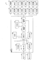
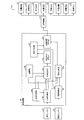
- FIG. 9 is a block diagram showing the configuration of the power generation system 30.
- the control device 40 includes a time management unit 40a, a light amount acquisition unit 40b, a light amount comparison unit 40c, a light amount ratio calculation unit 40d, a form switching instruction unit 40e, a temperature acquisition unit 40f, A temperature comparison unit 40g, a storage unit 40h, and a number calculation unit 40i are provided.
- the time management unit 40a functions as a timer.
- the time management unit 40a acquires the current time (t), and determines whether or not the acquired current time (t) has reached a predetermined time.
- the storage unit 40h is a storage unit that stores each parameter necessary for the processing of the power generation system 30 in advance.
- the storage unit 40h is not particularly limited, such as a volatile memory or a non-volatile memory, but is preferably a non-volatile memory in which recorded contents are not erased even when the power is turned off.
- the storage unit 40h stores a desired light amount (X) in the greenhouse 35 and a desired temperature (Y) in the greenhouse 35.
- the desired light quantity (X) in the greenhouse 35 and the desired temperature (Y) in the greenhouse 35 are preferably stored in the storage unit 40h as a table, for example, so as to change in association with time and season. .
- the method for storing the desired light quantity (X) in the greenhouse 35 and the desired temperature (Y) in the greenhouse 35 is not limited to this.
- the storage unit 40h may further store the width d of the power generation device 20, the gap w between the plurality of power generation devices 20, the number n of the power generation devices 20 included in the power generation system 30, and the like.
- the time management unit 40a determines that the current time (t) has reached a predetermined time, the time management unit 40a outputs acquisition instruction information for the actually measured light amount (x) in the greenhouse 35 to the light amount acquisition unit 40b, and the light amount
- the read instruction information of the registration data stored in the storage unit 40h is output to the comparison unit 40c and the temperature comparison unit 40g, respectively.
- the light amount acquisition unit 40b acquires the acquisition instruction information of the actually measured light amount (x) in the greenhouse 35 from the time management unit 40a
- the light amount acquisition unit 40b acquires the actually measured light amount (x) in the greenhouse 35 from the light amount sensor 33.
- (X) is output to the light quantity comparison unit 40c.
- the light quantity comparison unit 40c compares the measured light quantity (x) in the greenhouse 35 with the desired light quantity (X) stored in the storage unit 40h in advance, and compares the result with the light quantity ratio calculation unit 40d or the temperature acquisition unit. Output to 40f.
- the light quantity comparison unit 40c when acquiring the registration data reading instruction information from the time management unit 40a, acquires the desired light quantity (X) of the greenhouse 35 stored in advance as registration data in the storage unit 40h.
- the light amount comparison unit 40c compares the measured light amount (x) acquired from the light amount acquisition unit 40b with the desired light amount (X) acquired from the storage unit 40h.
- the light quantity comparison unit 40c determines that the actually measured light quantity (x) is greater than the desired light quantity (X)
- the measured light quantity (x) and the desired light quantity (X) are output to the light quantity ratio calculating unit 40d as a comparison result. To do.
- the light quantity comparison unit 40c determines that the actually measured light quantity (x) is equal to or less than the desired light quantity (X)
- the light quantity comparison unit 40c outputs acquisition instruction information of the actually measured temperature (y) to the temperature acquisition unit 46 as a comparison result.
- the light amount ratio calculation unit 40d calculates a light amount ratio (desired light amount (X) / measured light amount (x)) that is a ratio of the desired light amount (X) to the actually measured light amount (x).
- the light amount ratio calculation unit 40d calculates the light amount ratio (desired light amount (X) / measured light amount (x)) when the measured light amount (x) and the desired light amount (X) are obtained from the light amount comparison unit 40c.
- the light quantity ratio is output to the number calculation unit 40i.
- the number calculation unit 40i calculates the number of the power generation devices 20 in the power generation mode (1) in order to shield sunlight incident on the greenhouse 35 at a ratio corresponding to the light amount ratio calculated by the light amount ratio calculation unit 40d. It is.
- the number calculation unit 40i numerical values of the width d of the power generation device 20, the gap w between the plurality of power generation devices 20, and the number n of the power generation devices 20 are stored in advance.
- the width d of the power generation device 20, the gap w between the plurality of power generation devices 20, and the number n of the power generation devices 20 are stored in the storage unit 40h, not the number calculation unit 40i, and the number calculation is performed when necessary.
- the unit 40i may read from the storage unit 40h.
- the number calculation unit 40i calculates the ratio of the amount of light that can be cut out of the amount of sunlight currently incident on the greenhouse 35 from the light amount ratio acquired from the light amount ratio calculation unit 40d, and is necessary in the greenhouse 35. Calculate the ratio of the amount of light.
- the number calculation unit 40i based on the width d of the power generation device 20, the gap w between the plurality of power generation devices 20, and the number n of the power generation devices 20, is designed to reduce the amount of sunlight incident on the greenhouse 35 at a minimum. Calculate the percentage.
- the number calculation part 40i is the lighting form among the electric power generation apparatuses 20 with which the electric power generation system 30 is provided from the ratio of the light quantity required in the greenhouse 35 and the ratio of the light quantity of the sunlight incident on the greenhouse 35 at the minimum. (2) Or the number of the power generators 20 set as the power generation mode (1) and the number of the power generators 20 set as the power generation mode (1) are calculated.
- the number calculation unit 40i outputs the calculated information indicating the number of power generation devices 20 in the power generation mode to the mode switching instruction unit 40e.
- the form switching instruction unit 40e When acquiring the information indicating the number from the number calculating unit 40i, the form switching instruction unit 40e outputs the form switching instruction information to the power generation form (1) to the switching mechanism 31 indicated by the information indicating the number, The acquisition instruction information of the actually measured temperature (y) in the greenhouse 35 is output to the temperature acquisition unit 40f.
- indication part 40e acquires the instruction information to switch the electric power generating apparatus 20 to the lighting form (2) or the lighting form (3) from the temperature comparison part 40g, the form switch to the power generation form (1) will be carried out.
- the mode switching instruction information to the lighting mode (2) or the lighting mode (3) is output to the switching mechanism 31 that has not output the instruction information.
- the temperature acquisition unit 40f acquires the acquisition instruction information on the measured temperature (y) in the greenhouse 35 from the form switching instruction unit 40e or the light amount comparison unit 40c
- the temperature acquisition unit 40f acquires the measured temperature (y) in the greenhouse 35 from the temperature sensor 34. Then, the acquired measured temperature (y) is output to the temperature comparison unit 40g.
- the temperature comparison unit 40g compares the measured temperature (y) in the greenhouse 35 with the desired temperature (Y) stored in the storage unit 40h in advance, and outputs the comparison result to the configuration switching instruction unit 40e. Is.
- the temperature comparison unit 40g acquires the registration data reading instruction information from the time management unit 40a, the temperature comparison unit 40g acquires the desired temperature (Y) of the greenhouse 35 stored in advance as registration data in the storage unit 40h.
- the temperature comparison unit 40g compares the measured temperature (y) acquired from the temperature acquisition unit 40f with the desired temperature (Y) acquired from the storage unit.
- the temperature comparison unit 40g determines that the actually measured temperature (y) is higher than the desired temperature (Y), as a comparison result, instruction information for switching the power generation apparatus 20 to the daylighting mode (3) is given. To the unit 40e.
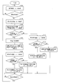
- FIG. 10 is a flowchart showing processing of the power generation system 30.
- each power generator 20 is in a daylighting mode (b) as an initial state.
- the time management unit 40a acquires the current time (t) (step S101).
- the time management unit 40a determines whether or not the acquired current time (t) is a predetermined time set in advance (step S102). When it is determined that the acquired current time (t) is a predetermined time (YES in step S102), the time management unit 40a sends the measured light amount (x) in the greenhouse 35 to the light amount acquisition unit 40b. The acquisition instruction information is output, and the registered data reading instruction information is output to the light amount comparison unit 40c and the temperature comparison unit 40g, respectively.
- the light quantity acquisition unit 40b obtains the acquisition instruction information of the actual light quantity (x) in the greenhouse 35 from the time management part 40a, the actual light quantity (x) in the greenhouse 35 measured by the light quantity sensor 33 from the light quantity sensor 33. ) Is acquired (step S103). Then, the light quantity acquisition unit 40b outputs the actually measured light quantity (x) acquired from the light quantity sensor 33 to the light quantity comparison unit 40c.
- the light quantity comparison part 40c will acquire the desired light quantity (X) of the greenhouse 35 previously memorize
- the temperature comparison unit 40g acquires the registration data read instruction information from the time management unit 40a
- the temperature comparison unit 40g acquires the desired temperature (Y) of the greenhouse 35 stored in advance as registration data from the storage unit 40h (step S104). ).
- the light amount comparison unit 40c determines whether or not the actually measured light amount (x) acquired from the light amount acquisition unit 40b is larger than the desired light amount (X) acquired from the storage unit 40h (step S105).
- the light quantity comparison unit 40c determines that the actually measured light quantity (x) is larger than the desired light quantity (X) (YES in step S105)
- the light quantity ratio calculation of the actually measured light quantity (x) and the desired light quantity (X) is performed. To the unit 40d.
- the light quantity ratio calculating unit 40d acquires the measured light quantity (x) and the desired light quantity (X) from the light quantity comparing unit 40c, it calculates the light quantity ratio (desired light quantity (X) / measured light quantity (x)) ( Step S106). Then, the light amount ratio calculation unit 40d outputs the calculated light amount ratio to the number calculation unit 40i.
- the number calculation unit 40i acquires the light amount ratio from the light amount ratio calculation unit 40d, the power generation mode in all the power generation devices 20 so as to shield sunlight incident into the greenhouse 35 at a ratio close to the light amount ratio ( The number of the power generators 20 to be 1) is calculated. Then, the number calculation unit 40i outputs information indicating the calculated number to the form switching instruction unit 40e.
- indication part 40e will acquire the information which shows the number from the number calculation part 40i, and the form switching instruction
- Step S107 the switching mechanism 31 which acquired the form switching instruction
- the temperature acquisition unit 40f when the temperature acquisition unit 40f acquires the acquisition instruction information on the actually measured temperature (y) in the greenhouse 35 from the form switching instruction unit 40e, the temperature acquisition unit 40f measures the actual temperature (y in the greenhouse 35 measured by the temperature sensor 34 from the temperature sensor 34. ) Is acquired (step S108).
- the temperature acquisition unit 40f outputs the actually measured temperature (y) acquired from the temperature sensor 34 to the temperature comparison unit 40g.
- the temperature comparison unit 40g determines whether or not the actually measured temperature (y) acquired from the temperature acquisition unit 40f is higher than the desired temperature (Y) acquired from the storage unit 40h (step S109).
- the temperature comparison unit 40g causes the configuration switching instruction unit 40e to switch the power generation device 20 to the lighting configuration (3). Outputs instruction information for switching.
- the form switching instruction unit 40e obtains instruction information for switching the power generation device 20 to the daylighting form (3) from the temperature comparison unit 40g, the form switching to the power generation form (1) among the plurality of switching mechanisms 31 is performed.
- the form switching instruction information to the lighting form (3) is output to the remaining switching mechanisms 31 that did not output the instruction information.
- Step S110 the switching mechanism 31 which acquired the form switching instruction
- the time management unit 40a determines whether or not a predetermined time has elapsed (step S111).
- step S111 If the time management unit 40a determines that a predetermined time has elapsed (YES in step S111), the process returns to step S101.
- step S109 when the temperature comparison unit 40g determines that the measured temperature (y) is equal to or lower than the desired temperature (Y) (NO in step S109), the temperature comparison unit 40g causes the configuration switching instruction unit 40e to Instruction information for switching the power generation device 20 to the daylighting mode (2) is output.
- the form switching instruction unit 40e acquires instruction information indicating that the power generation device 20 is switched to the daylighting form (2) from the temperature comparison unit 40g, the form switching to the power generation form (1) among the plurality of switching mechanisms 31 is performed.
- the form switching instruction information to the lighting form (2) is output to the remaining switching mechanisms 31 that did not output the instruction information.
- Step S112 the switching mechanism 31 which acquired the form switching instruction
- step S105 the light amount comparison unit 40c determines that the actually measured light amount (x) acquired from the light amount acquisition unit 40b is equal to or less than the desired light amount (X) acquired from the storage unit 40h (NO in step S105).
- the acquisition instruction information of the actually measured temperature (y) in the greenhouse 35 is output to the temperature acquisition unit 40f.
- the temperature acquisition part 40f will acquire the measurement instruction
- the temperature acquisition unit 40f outputs the actually measured temperature (y) acquired from the temperature sensor 34 to the temperature comparison unit 40g.
- the temperature comparison unit 40g determines whether or not the actually measured temperature (y) acquired from the temperature acquisition unit 40f is higher than the desired temperature (Y) acquired from the storage unit 40h (step S114).
- the temperature comparison unit 40g supplies all the power generation devices 20 to the configuration switching instruction unit 40e in the lighting configuration (3). Instruction information for switching to is output.
- the mode switching instruction unit 40e sends all the switching mechanisms 31 to the daylighting mode (3).
- the form switching instruction information is output.
- step S115 the switching mechanism 31 which acquired the form switching instruction
- step S114 when the temperature comparison unit 40g determines that the actually measured temperature (y) acquired from the temperature acquisition unit 40f is equal to or lower than the desired temperature (Y) acquired from the storage unit 40h (NO in step S114).
- the temperature comparison unit 40g outputs instruction information indicating that all the power generation apparatuses 20 are switched to the daylighting form (2) to the form switching instruction part 40e.
- the form switching instruction unit 40e acquires instruction information indicating that all the power generation devices 20 are switched to the daylighting form (2) from the temperature comparison unit 40g, the form switching instruction part 40e is transferred to the daylighting form (2).
- the form switching instruction information is output.
- step S116 the switching mechanism 31 which acquired the form switching instruction
- the total number of power generation devices 20 is switched to the daylighting mode (2) (step S116). Then, the process proceeds to step S111.
- each parameter required for processing of the power generation system 30 is as follows.
- Y Desired temperature
- the time management unit 40a acquires the current time (t) (step S101), and the acquired current time (t) is a predetermined time set in advance. (YES in step S102), the time management unit 40a then outputs acquisition instruction information of the actually measured light amount (x) in the greenhouse 35 to the light amount acquisition unit 40b, and the light amount comparison unit 40c and the temperature comparison unit. The registered data read instruction information is output to 40g.
- the light quantity acquisition part 40b acquires the actually measured light quantity (x) in the greenhouse 35 from the time management part 40a
- the light quantity acquisition part 40b acquires the actually measured light quantity (x) in the greenhouse 35 from the light quantity sensor 33 (step S103). ), And outputs the acquired actually measured light quantity (x) to the light quantity comparison unit 40c.
- the light quantity comparison unit 40c acquires the registration data read instruction information from the time management unit 40a
- the light quantity comparison unit 40c acquires a desired light quantity (X) of the greenhouse 35 stored in advance as registration data from the storage unit 40h.
- the temperature comparison unit 40g acquires the registration data read instruction information from the time management unit 40a
- the temperature comparison unit 40g acquires the desired temperature (Y) of the greenhouse 35 stored in advance as registration data from the storage unit 40h (step S104).
- the light amount comparison unit 40c determines that the actually measured light amount (x) is larger than the desired light amount (X) (YES in step S105).
- the actually measured light quantity (x) and the desired light quantity (X) are output to the light quantity ratio calculation unit 40d.
- the number calculation part 40i will acquire the light quantity ratio from the light quantity ratio calculation part 40d, and the electric power generation form (1) in all the power generators 20 will shield the sunlight which injects into the greenhouse 35 by the ratio close
- the number calculation unit 40i performs the calculation as follows.
- the number calculation unit 40i calculates the amount of light entering the greenhouse 35 at a minimum in the design of the current power generation system 30.
- the width d of the power generation device 20 is 300 mm and the gap w between the power generation devices 20 is 150 mm
- the number calculating unit 40i has a required light quantity of 50% in the greenhouse 35, and since the light quantity incident on the greenhouse 35 is 1/3 at a minimum, the remaining 1/6 light quantity is stored in the greenhouse 35. It is calculated that introduction is necessary.
- the number calculation unit 40i is set in advance so that the introduction of 1/12 light quantity is expected.
- the number calculation unit 40i calculates that the number of the power generation devices 20 in the daylighting mode (2) or the daylighting mode (3) is two out of the eight power generation devices 20, and generates the power generation mode.
- the number of devices 20 is calculated to be six.
- the number calculating unit 40i outputs information indicating the number indicating that the number of the power generation devices 20 in the power generation form is six to the form switching instruction unit 40e.
- indication part 40e will acquire the form switch instruction
- the temperature acquisition unit 40f when the temperature acquisition unit 40f acquires the acquisition instruction information on the actually measured temperature (y) in the greenhouse 35 from the form switching instruction unit 40e, the temperature acquisition unit 40f measures the actual temperature (y in the greenhouse 35 measured by the temperature sensor 34 from the temperature sensor 34. ) Is acquired (step S108). Then, the temperature acquisition unit 40f outputs the actually measured temperature (y) acquired from the temperature sensor 34 to the temperature comparison unit 40g.
- the temperature comparison unit 40g determines whether the remaining two power generation devices 20 are in the daylighting mode (2) or the daylighting mode (3), and the actually measured temperature (y) and the desired temperature (Y ) Is compared (step S109).
- the temperature comparison unit 40g determines that the actually measured temperature (y) is higher than the desired temperature (Y) (YES in step S109).
- Instruction information for switching the power generation apparatus 20 to the daylighting form (3) is output to the form switching instruction unit 40e.
- the form switching instruction unit 40e acquires instruction information for switching the power generation device 20 to the daylighting form (3) from the temperature comparison unit 40g, the form switching to the power generation form (1) among the eight switching mechanisms 31 is performed.
- the form switching instruction information to the lighting form (3) is output to the remaining two switching mechanisms 31 that did not output the instruction information.
- the two switching mechanisms 31 that have acquired the form switching instruction information from the form switching instruction unit 40 e to the lighting form (3) use the power generation apparatus 20 connected to itself as the lighting form ( 3) (step S110). Thereby, the remaining two power generation devices 20 among the eight power generation devices 20 are switched to the daylighting mode (3).
- step S111 when the time management unit 40a determines that a predetermined time has elapsed (YES in step S111), the process returns to step S101.
- FIG. 11 is a diagram illustrating a configuration of a power generation system 130 including the power generation device 20.
- the power generation system (light quantity adjustment system) 130 includes a single switching mechanism 131 for the plurality of power generation devices 20 and a control device 140 instead of the control device 40. 30. Furthermore, the power generation system 130 is also different from the power generation system 30 in that it takes two types of power generation modes based on the temperature in the greenhouse. Other configurations of the power generation system 130 are the same as those of the power generation system 30.
- the power generation system 130 includes a plurality of power generation devices 20, a switching mechanism 131, a control device 140, and a sensor unit 32.
- One switching mechanism 131 is provided for the plurality of power generation apparatuses 20, and the switching mechanism 131 is connected to all of the plurality of power generation apparatuses 20.
- the switching mechanism 131 can collectively change the angles of the plurality of power generation devices 20 based on an instruction from the control device 140.
- the switching mechanism 131 includes a belt, a rack (linear gear), and a pinion gear, and is configured by a simple mechanism.
- the switching mechanism 131 adjusts the rotation angle of the plurality of power generation devices 20 little by little based on an instruction from the control device 140, and changes the ratio of daylighting and power generation.
- the power generation system 130 determines the rotation angle of each power generation device 20 according to the light amount sensor 33, the temperature sensor 34, and pre-registered data (when and what temperature and light amount are desired) installed in the greenhouse 35. Adjustment is made according to a flowchart described later.
- FIG. 12 is a figure which shows a power generation form (4)
- (b) is a figure which shows a power generation form (5).
- the power generation system 130 takes the power generation mode (4) or the power generation mode (5) according to the amount of light incident on the greenhouse, not the power generation mode (1). Then, the power generation system 130 selects the power generation mode (4) or the power generation mode (5) depending on whether the greenhouse needs to be heated.
- the incident direction of the sunlight to the electric power generating apparatus 20 shall be a direction which faces a downward direction from the upper direction of a perpendicular direction.
- the power generation mode (4) is a mode for generating power (blocking incident light to the power generation apparatus 20) and transmitting part of the incident light as it is.
- This power generation mode (4) is referred to as a fourth mode.
- the fourth mode is a mode for generating power, adjusting the amount of light collected into the greenhouse, and warming the greenhouse (that is, making infrared light incident).
- the rotational position of the power generation device 20 in the fourth mode is referred to as a “fourth position” (fourth position, first position).
- the fourth position is to allow a part of incident light to the power generation device 20 to enter the light receiving surface 21a of the solar cell 21 and to transmit the power generation device 20 as it is without entering the remaining part to the plate 22. This is the rotational position of the power generation device 20.
- the fourth position is such that the light receiving surface 21a of the solar cell 21 is inclined at a predetermined angle with respect to the incident direction (vertical direction) of sunlight, and the plate 22 Is a position parallel to the incident direction (vertical direction) of sunlight.
- the light receiving surface 21a of the solar cell 21 and the incident direction (vertical direction) of sunlight are non-parallel, and the plate 22 is parallel to the incident direction (vertical direction) of sunlight. Is the position.
- the angle at which the light receiving surface 21a of the solar cell 21 is inclined with respect to the incident direction (vertical direction) of sunlight is determined according to the amount of light transmitted through the power generation device 20 among the incident light to the power generation device 20 (for details). Will be described later).
- the fourth position can be obtained by rotating the power generation device 20 counterclockwise from the second position by a predetermined angle (for example, 30 °).
- the power generation device 20 By setting the power generation device 20 to the fourth form, it is possible to generate power, adjust the amount of light collected into the greenhouse, and warm the greenhouse.
- the power generation mode (5) is a mode for generating power (blocking incident light to the power generation apparatus 20) and blocking and transmitting infrared light of part of the incident light.
- This power generation mode (5) is referred to as a fifth mode.
- the fifth form is a form for generating power, adjusting the amount of light collected into the greenhouse, and preventing warming of the greenhouse (that is, shielding infrared light).
- the rotational position of the power generation device 20 in the fifth embodiment is referred to as a “fifth position”.
- the fifth position is a rotational position of the power generation apparatus 20 for causing a part of incident light to the power generation apparatus 20 to enter the light receiving surface 21a of the solar cell 21 and a remaining part to the plate 22.
- the fifth position is such that the light receiving surface 21a of the solar cell 21 is inclined at a predetermined angle with respect to the incident direction (vertical direction) of sunlight, and the plate 22 Is a position perpendicular to the incident direction (vertical direction) of sunlight.
- the fifth position is such that the light receiving surface 21a of the solar cell 21 and the incident direction (vertical direction) of sunlight are non-parallel, and the plate 22 is perpendicular to the incident direction (vertical direction) of sunlight. Is the position.
- the angle at which the light receiving surface 21a of the solar cell 21 is inclined with respect to the incident direction (vertical direction) of sunlight depends on the amount of light transmitted through the power generation device 20 among the incident light to the power generation device 20. Determine (details will be described later).
- the fifth position can be obtained by rotating the power generation device 20 counterclockwise by an angle obtained by subtracting a predetermined angle from 180 ° (for example, 150 °) from the second position.
- the power generation device 20 By setting the power generation device 20 to the fifth form, it is possible to generate power, adjust the amount of light collected into the greenhouse, and prevent warming of the greenhouse.
- FIG. 13 is a block diagram illustrating a configuration of a power generation system 130 including the control device 140.
- the control device 140 is different from the control device 40 in that an angle calculation unit 140i is provided instead of the number calculation unit 40i.
- the control device 140 includes a time management unit 40a, a light amount acquisition unit 40b, a light amount comparison unit 40c, a light amount ratio calculation unit 40d, a form switching instruction unit 40e, a temperature acquisition unit 40f, A temperature comparison unit 40g, a storage unit 40h, and an angle calculation unit 140i are provided.
- the angle calculation unit 140i Since the angle calculation unit 140i shields sunlight incident on the greenhouse 35 at a ratio corresponding to the light amount ratio calculated by the light amount ratio calculation unit 40d, the angle calculation unit 140i has the power generation mode (4) or the power generation mode (5). A predetermined angle that is an inclination angle of the solar cell 21 with respect to the incident direction (or vertical direction) of sunlight is calculated.
- the angle calculation unit 140i numerical values of the width d of the power generation device 20, the gap w between the plurality of power generation devices 20, and the number n of the power generation devices 20 are stored in advance.
- the width d of the power generation device 20, the gap w between the plurality of power generation devices 20, and the number n of the power generation devices 20 are stored not in the angle calculation unit 140i but in the storage unit 40h, and the angle calculation is performed when necessary.
- the unit 140i may read from the storage unit 40h.
- the angle calculation unit 140i calculates the ratio of the amount of light that can be cut out of the amount of sunlight that is currently incident on the greenhouse 35 from the light amount ratio acquired from the light amount ratio calculation unit 40d. Calculate the ratio of the amount of light.
- the angle calculation unit 140i determines, based on the design, at least the amount of sunlight incident on the greenhouse 35 from the width d of the power generation device 20, the gap w between the plurality of power generation devices 20, and the number n of the power generation devices 20. Calculate the percentage.
- the angle calculation unit 140i tilts all the power generation devices 20 included in the power generation system 30 from the ratio of the light amount required in the greenhouse 35 and, at the minimum, the ratio of the amount of sunlight incident on the greenhouse 35. Is calculated.
- the angle calculation unit 140i outputs information indicating the calculated predetermined angle to the form switching instruction unit 40e.
- the form switching instruction unit 40e acquires information indicating a predetermined angle from the angle calculation unit 140i, and acquires instruction information for switching to the power generation mode (4) or the power generation mode (5) from the temperature comparison unit 40g. Instruction information for switching all the power generation devices 20 to the power generation mode (4) or the power generation mode (5) is output to the mechanism 131 at a predetermined angle. Thereby, all the power generators 20 are switched to a power generation mode (4) or a power generation mode (5) at a predetermined angle.
- the form switching instruction unit 40e When acquiring information indicating a predetermined angle from the angle calculation unit 140i, the form switching instruction unit 40e outputs acquisition instruction information of the actually measured temperature (y) in the greenhouse 35 to the temperature acquisition unit 40f. Furthermore, when the mode switching instruction unit 40e acquires instruction information for switching the power generation device 20 to the power generation mode (4) from the temperature comparison unit 40g, the mode switching instruction unit 40e The form switching instruction information for switching to the power generation form (4) at an angle is output.
- indication part 40e acquires the instruction
- FIG. 14 is a flowchart showing processing of the power generation system 130.
- step S105 the light amount ratio calculation unit 40d calculates the light amount ratio (desired light amount (X) / measured light amount (x)) through the same processing as step S106 (step S106).
- the ratio calculation unit 40d outputs the calculated light amount ratio to the angle calculation unit 140i.
- the angle calculation unit 140i obtains the light amount ratio from the light amount ratio calculation unit 40d
- the angle calculation unit 140i tilts all the power generation devices 20 so as to shield sunlight incident on the greenhouse 35 at a ratio close to the light amount ratio. Is calculated (step S207).
- the angle calculation unit 140i outputs information indicating the calculated predetermined angle to the form switching instruction unit 40e.
- indication part 40e will output the acquisition instruction information of the measured temperature (y) in the greenhouse 35 to the temperature acquisition part 40f, if the information which shows a predetermined angle from the angle calculation part 140i is acquired. Thereafter, the same processing as in steps S108 and S109 is performed.
- the temperature comparison unit 40g determines that the measured temperature (y) is higher than the desired temperature (Y) (YES in step S109), and the temperature comparison unit 40g connects the power generation device 20 to the configuration switching instruction unit 40e. Instruction information for switching to the power generation mode (5) is output.
- the mode switching instruction unit 40e When the form switching instruction unit 40e obtains instruction information for switching the power generation device 20 to the power generation mode (5) from the temperature comparison unit 40g, the mode switching instruction unit 40e causes the power generation device 20 to generate power at a predetermined angle with respect to the switching mechanism 131.
- the form switching instruction information for switching to form (5) is output.
- step S210 the switching mechanism 131 will switch all the power generators 20 connected to self to the power generation form (5), if the form switching instruction information is acquired from the form switching instruction
- step S109 when the temperature comparison unit 40g determines that the measured temperature (y) is equal to or lower than the desired temperature (Y) (NO in step S109), the temperature comparison unit 40g causes the configuration switching instruction unit 40e to Instruction information for switching the power generation device 20 to the power generation mode (4) is output.
- the mode switching instruction unit 40e When acquiring the instruction information for switching the power generation device 20 to the power generation mode (4) from the temperature comparison unit 40g, the mode switching instruction unit 40e causes the power generation device 20 to generate power at a predetermined angle with respect to the switching mechanism 131.
- the form switching instruction information for switching to form (4) is output.
- each of the switching mechanism 131 will switch all the power generators 20 connected to self to the power generation form (4), if the form switching instruction information is acquired from the form switching instruction
- step S105 the process returns to step S101 through step S113, YES in step S114, YES in step S115, and YES in step S111.
- step S113 step S114 NO, step S116 and step S111 YES
- the process returns to step S101.
- each parameter required for processing of the power generation system 130 is as follows.
- Y Desired temperature
- Width of power generation device 20 (power generation form) d: 300 mm ⁇ Gap between power generation devices 20 (power generation form) w: 150 mm -Number n of power generation devices 20: 8
- the initial configuration of all power generation devices 20 is the daylighting configuration (2).
- step S101 the same processing is performed from step S101 to S105.
- the light amount comparison unit 40c determines that the actually measured light amount (x) is larger than the desired light amount (X) (YES in step S105).
- the actually measured light quantity (x) and the desired light quantity (X) are output to the light quantity ratio calculation unit 40d.
- the angle calculation unit 140i tilts all the power generation devices 20 so as to shield sunlight incident on the greenhouse 35 at a ratio close to the light amount ratio. Is calculated (step S207).
- the angle calculation unit 140i performs calculation as follows.
- the angle calculation unit 140i calculates, at a minimum, the amount of light that enters the greenhouse 35 in the design of the current power generation system 30.
- the angle calculation unit 140i has a light amount of 67% required in the greenhouse 35, and at the minimum, the amount of light incident on the greenhouse 35 is 1/3. It is calculated that introduction is necessary.
- the angle calculation unit 140i calculates a predetermined angle of 30 ° in order to shield half of the sunlight incident on all the power generation devices 20 and transmit the remaining half. That is, the angle calculation unit 140i calculates the rotation angle from the daylighting state (2), which is an expected form, as 30 ° counterclockwise or 150 ° counterclockwise.
- the angle calculation unit 140i outputs information indicating the calculated predetermined angle to the form switching instruction unit 40e.
- step S109 the temperature comparison unit 40g determines whether or not infrared rays should be cut. In other words, the temperature comparison unit 40g determines whether the rotation angle from the lighting state (2) should be 30 ° counterclockwise or 150 ° counterclockwise.
- the temperature comparison unit 40g determines that the measured temperature (y) is equal to or lower than the desired temperature (Y) (that is, from the lighting state (2)).
- the temperature comparison unit 40g instructs the mode switching instruction unit 40e to switch the power generation device 20 to the power generation mode (4). Output instruction information.
- indication part 40e will acquire the instruction
- step S212 when acquiring the form switching instruction information from the form switching instruction unit 40e, the switching mechanism 131 switches all the power generation devices 20 connected to itself to the power generation form (4) at 30 ° counterclockwise (step S212). ). Thereafter, after YES in step S111, the process returns to step S101.
- FIG. 15 is sectional drawing showing the structure of the electric power generating apparatus 120 concerning 2nd Embodiment, (a) is sectional drawing of the electric power generating apparatus 120 of the form which generate
- FIG. 15 represents the power generator 120 of the first form
- (b) represents the power generator 120 of the second form
- (c) represents the power generator 120 of the third form.
- the power generation device 120 is provided with a condensing lens (lens member) 125 in place of the solar cell 21 provided in the power generation device 20.
- the power generation device 120 includes a solar cell 121 disposed inside.
- the power generation device 120 includes a plate (second heat ray shielding member) 122 and a plate (first heat ray shielding member) 124 instead of the plate 22 provided in the power generation device 20.
- the power generation device 120 includes a hinge (third rotation shaft) 123. The hinge 23 is arranged on the back surface of the back surface of the solar cell 121.
- the condensing lens 125 has a plate shape as an example. When the power generation device 120 is in the first form, the condensing lens 125 condenses sunlight and emits the condensed sunlight to the solar cell 121.
- the lens The shape of the condenser lens 125 is not limited to a plate shape.
- the condensing lens 125 is arranged on one side of the triangular prism shape in which the solar cell 21 is arranged in the power generation device 20.
- the condensing lens 125 is a surface formed by the beam member 14, the beam member 15, one side of the support plate 11a (not shown in FIGS. 15A to 15C), and one side of the support plate 11b. Is attached to the power generator 120. As described above, the condensing lens 125 is arranged so as to be rotatable in a direction around the rotation shaft 12.
- a hinge 123 is disposed in the vicinity of the beam member 15 on the back surface (the surface on the side facing the beam member 13) of the condenser lens 125.
- the hinge 123 extends in a direction parallel to the hinge 23.
- the hinge 123 a general structure that is used by screwing the material may be used.
- the hinge 123 may be fixed to the back surface of the condenser lens 125 and the plate 122 with an adhesive.
- the fixing method of the hinge 123, the back surface of the condensing lens 125, and the plate 122 is not limited to this.
- the material of the hinge 123 is preferably a light transmissive plastic or the like, but is not limited thereto.
- the position where the hinge 123 is arranged is not limited to the back surface of the condensing lens 125, and may be a side surface of the condensing lens 125, for example. Further, it may be separated from the condenser lens 125.
- the arrangement position and configuration of the hinge 123 are the same as those of the hinge 23.
- a plate 122 having an infrared cut function is disposed on the back surface of the condenser lens 125 via a hinge 123.
- the condenser lens 125 for example, a biconvex lens, a plano-convex lens, or a Fresnel lens can be used.
- the condensing lens 125 is preferably a Fresnel lens having a flat incident surface for receiving sunlight and an exit surface (back surface) for irradiating sunlight toward the solar cell 121 having a substantially triangular cross section. This is because the Fresnel lens is easy to handle in terms of weight, cost, and usage environment.
- the condensing lens 125 can be made of, for example, a thin glass generally used for a normal solar cell module (solar power generation system), weather resistant grade acrylic, polycarbonate, or the like.
- the material of the condensing lens 125 is not limited to the above, and these materials may have a multilayer structure.
- the condensing lens 125 it is preferable to select a material having a high transmittance of the sensitivity wavelength light of the solar cell element used for the solar cell 121 and having weather resistance.
- an appropriate ultraviolet absorber may be added to these materials for the purpose of preventing ultraviolet degradation of the condenser lens 125 itself and other members.
- the solar cell 121 is arranged in a corner portion including the beam member 13 in the power generator 120.
- the solar cell 121 is disposed between the rotating shaft 12 and the beam member 13 so as to be parallel to the condenser lens 125.
- each of the sides is fixed by a support plate 11a (not shown in FIGS. 15A to 15C) and 11b.
- the plate-like solar cell 121 is arranged so as to be rotatable about the rotating shaft 12 extending in one direction. For this reason, the amount of incident light shielded by the solar cell 121 can be adjusted by controlling the rotational position of the solar cell 21 with respect to the rotating shaft 12. As a result, the amount of transmitted light from the power generation device 20 can be adjusted, and the amount of power generated by the solar cell 21 can also be adjusted.
- the solar cell 121 is described as having a rectangular shape, but the shape of the solar cell 121 is not limited to a rectangular shape.
- the power generator 120 has a beam material 13 as a common apex, and has a similar shape, a triangular shape formed by the beam material 13 and the solar cell 121, and a triangular shape formed by the beam material 13 and the condenser lens 125. have.
- the surface facing the beam member 13 is a back surface (one surface) 121b, and the surface opposite to the back surface 121b is a light receiving surface 121a for receiving incident light such as sunlight. .
- the light receiving surface 121a is directed to the condenser lens 125. That is, the light receiving surface 121 a is also a surface facing the condenser lens 125.
- a hinge 23 is arranged on the back surface 121b of the solar cell 121 and in the vicinity of one side in the longitudinal direction.
- the hinge 23 extends so as to be parallel to the rotating shaft 12 and the hinge 123.
- a plate 124 having an infrared cut function is disposed on the back surface 121b of the solar cell 121 via a hinge 23.
- the plates 122 and 124 are plates having an infrared cut function, which shields infrared rays (heat rays) from incident light such as sunlight and transmits visible light.
- the plate 122 is attached to the hinge 123 so that one end 122a is rotatable about the hinge 123. That is, the end 122 a is connected to the back surface of the condenser lens 125 via the hinge 123.
- the other end 122 b that is paired with the one end 122 a of the plate 122 (opposite the end 122 a) is not connected to the back surface of the condenser lens 125. For this reason, the other end 122b of the plate 122 is lowered downward due to gravity.
- the plate 124 is attached to the hinge 23 such that one end portion 124a is rotatable about the hinge 23. That is, the end portion 124 a is connected to the back surface 121 b of the solar cell 121 through the hinge 23.
- the other end portion 124 b that forms a pair with one end portion 124 a of the plate 124 is not connected to the back surface 121 b of the solar cell 121. For this reason, the other end 124b of the plate 124 is lowered downward due to gravity.
- the electric power generating apparatus 120 can be obtained with a simple configuration.
- the plate 122 has its end 122b in contact with the light receiving surface 121a of the solar cell 121, whereby the maximum angle with respect to the condenser lens 125 is defined. Thereby, the position of the plate 122 with respect to the rotating shaft 12 (that is, the angle of the plate 122 with respect to the horizontal plane) can be adjusted.
- the plate 124 has its end portion 124b in contact with the beam member 13 so that the maximum angle with respect to the solar cell 121 is defined. Thereby, the position of the plate 124 with respect to the rotating shaft 12 (that is, the angle of the plate 124 with respect to the horizontal plane) can be adjusted.
- the incident angle of the infrared rays incident on the power generation device 120 with respect to the plates 122 and 124 can be adjusted, the amount of infrared rays transmitted from the power generation device 120 can be adjusted.
- the plate 122 and the plate 124 are rectangular in this embodiment, and the direction in which the end portions 122a and 122b and the end portions 124a and 124b extend is the longitudinal direction.
- the shape of the plates 122 and 124 is not limited to a rectangular shape.
- the plates 122 and 124 can be configured by attaching a film having an infrared cut function to glass or acrylic, or applying a paint having an infrared cut function.
- the solar cell 121 when the power generation device 120 is in the first form, the solar cell 121 is arranged so as to be perpendicular to the incident direction of sunlight. For this reason, sunlight can be received to the maximum extent.
- the plates 122 and 124 have their end portions 122b and 124b that are not fixed lowered downward due to gravity, respectively. Stops in contact with the beam member 13. In the power generation device 120, the solar cell 121 and the beam member 13 serve as stoppers, and the plates 122 and 124 do not come out from the rotation radius r around the rotation shaft 12.
- the power generation device 120 by setting the power generation device 120 to the first form, it is possible to collect sunlight by the condenser lens 125 and irradiate the light receiving surface 121a of the solar cell 121 with the collected sunlight. Thereby, the solar cell 121 can receive sunlight to the maximum extent by the light receiving surface 121a, and can shield light to the maximum extent. For this reason, by setting the power generation device 120 to the first mode, the sunlight incident on the greenhouse can be shielded to the maximum by the solar cell 121 and the power can be generated to the maximum by the light receiving surface 121a of the solar cell 121.
- the condenser lens 125 In the power generation device 120, sunlight can be condensed by the condenser lens 125, so that the solar cell 121 can be made small.
- the solar cell 121 is more expensive than the condenser lens 125. For this reason, compared with the case where a solar cell is distribute
- the power generation device 120 can be turned to the second position by rotating 90 ° clockwise from the first position, and the power generation device 120 can be in the second form.
- the end portion 122b of the plate 122 and the end portion 124b of the plate 124 that are not connected to the hinges 123 and 23 are lowered downward due to gravity. 13 does not come into contact with each other, so that the plates 122 and 124 are arranged in a direction parallel to the vertical direction.
- the power generation device 120 can transmit sunlight as much as possible. For this reason, by setting the power generator 120 in the second form, it is possible to make sunlight enter the greenhouse as much as possible, so that the sunlight can be taken into the greenhouse, and the infrared rays of sunlight are not shielded. Can be warmed.
- the power generation device 120 can be turned to the third position by rotating 90 ° counterclockwise from the first position, and the power generation device 120 can be in the third form.
- the end portion 122b of the plate 122 and the end portion 124b of the plate 124b that are not connected to the hinges 23 and 123 are in contact with the solar cell 121 and the beam member 13, respectively.
- the plate 122 and the plate 124 are arranged on the same plane. That is, a plane formed by the beam member 15 and one side in the longitudinal direction of the solar cell 121 is covered with the plate 122, and a plane formed by the one side in the longitudinal direction of the solar cell 121 and the beam member 13 is formed by the plate 124. Will be covered.
- the incident light which is sunlight
- the electric power generating apparatus 120 can permeate
- the power generation device 120 it is possible to take light in the greenhouse and shield the infrared rays of sunlight, so that excessive warming of the greenhouse can be prevented.
- a stopper for contacting the plate 122 may be provided separately as shown in FIG.
- FIG. 16 is a diagram illustrating the configuration of the power generation device 120 provided with the stopper 126.
- the shape and material of the stopper 126 can be configured similarly to the beam member 13 or the like.
- the stopper 126 is in the power generator 120 and is arranged in the locus of the rotating plate 122. Further, by providing the stopper 126, the vicinity of the end 122 b of the plate 122 abuts on the stopper 126 and does not abut on the solar cell 121. Thereby, interference with the solar cell 121 can be avoided.
- FIG. 17 is a diagram illustrating a configuration of a power generation system 330 according to the third embodiment.
- FIG. 18 is a cross-sectional view showing the configuration of the power generators 220a and 220b according to the third embodiment.
- FIG. 18A is a cross-sectional view of the power generators 220a and 220b in the form of generating power
- FIG. It is sectional drawing of the electric power generating apparatus 220a * 220b of the form which warms
- (c) is sectional drawing of the electric power generating apparatus 220a * 220b of the form which light-shields and shields a heat ray.
- FIG. 18A shows the power generators 220a and 220b of the first form
- FIG. 18B shows the power generators 220a and 220b of the second form
- FIG. 18C shows the power generators 220a and 220b of the third form. 220b.
- the power generation system (light quantity adjustment system) 330 includes a power generation system 130 shown in FIG. 11, a point provided with a plurality of power generation devices 220 a and 220 b instead of the plurality of power generation devices 20, and switching. The difference is that a switching mechanism 131a, 131b is provided instead of the mechanism 131.
- Other configurations of the power generation system 330 are the same as those of the power generation system 130.
- the power generation device 220a and the power generation device 220b have a line-symmetric shape (symmetric shape).
- the power generation device 220a and the power generation device 220b are alternately arranged side by side and in the vicinity of the roof 35a of the greenhouse 35 or the roof 35a.
- the power generation device 220a has the same shape as the power generation device 20 described above.
- the power generation device 220b has a shape that is line symmetric with respect to the ⁇ - ⁇ 'line, which is in the middle of the power generation device 220a.
- the solar cells 21 are arranged so as to be perpendicular to the incident direction of sunlight. For this reason, sunlight can be received to the maximum extent.
- the plate 22 of each of the power generation devices 220a and 220b is brought into contact with the respective beam members 13 and stopped by the respective end portions 22b that are not fixed due to gravity.
- the respective beam members 13 serve as stoppers, and the respective plates 22 do not come out from the rotation radii around the respective rotation shafts 12.
- each solar cell 21 can receive sunlight to the maximum extent by the light receiving surface 21a and shield light to the maximum extent. For this reason, by setting the power generation devices 220a and 220b to the first form, the solar cell 21 can shield the sunlight incident on the greenhouse to the maximum extent and can generate the maximum power on the light receiving surface 21a of the solar cell 21. .
- the power generation device 220a is rotated 90 ° clockwise from the first position, and the power generation device 220b is rotated 90 ° counterclockwise from the first position.
- Each of 220a and 220b can be in the second position, and each of the power generators 220a and 220b can be in the second form.
- the power generators 220a and 220b are configured such that the end portions 22b of the plates 22 that are not connected to the hinges 23 are lowered by gravity and do not contact the respective beam members 13, thereby.
- Each plate 22 is arranged in a direction parallel to the vertical direction.
- the power generation devices 220a and 220b can transmit sunlight as much as possible. For this reason, by making the power generators 220a and 220b into the second form, it is possible to make sunlight enter the greenhouse 35 as much as possible, so that the sunlight can be taken into the greenhouse 35, and the infrared rays of sunlight are not shielded. So you can warm the greenhouse.
- the power generation device 220a is rotated 90 ° counterclockwise from the first position, and the power generation device 220b is rotated 90 ° clockwise from the first position.
- the power generator 220a and the power generator 220b can be in the third form.
- the solar cells 21 of the power generation apparatuses 220a and 220b are parallel to the incident direction of sunlight, and the planes formed by the beam members 13 and the beam members 15 are respectively covered with the plates 22.
- the incident light that is sunlight passes through the respective plates 22 by setting the power generation devices 220a and 220b to the third form.
- the power generators 220a and 220b can transmit light having a shorter wavelength than infrared light, and can block infrared light in sunlight.
- the greenhouse 35 can be daylighted and the infrared rays of sunlight are shielded, so that excessive heating of the greenhouse can be prevented. it can.
- the power generators 220a and 220b may take a fourth form and a form that is a target of the fourth form. Or you may make it the electric power generating apparatus 220a * 220b take the form which becomes object with the 5th form and the said 5th form.
- the power generation device 220 a is in a fourth form
- the power generation device 220 b is in a form that is line symmetric about the ⁇ - ⁇ ′ line in FIG. 18 (the fourth form and the target form). .
- the power generators 220a and 220b have the fourth form and the fourth form and the target form, or the fifth form and the fifth form and the target form. Part of the incident light to each of the power generation devices 220a and 220b can be reflected by the solar cell 21, and the remaining part can be transmitted as it is from the plane between the beam members 13 and 15.
- the solar cells 21 are arranged to face each other in parallel or non-parallel while being inclined with respect to each other, and arranged facing each other. For this reason, the reflected light of sunlight that has entered one of the power generation devices 220 a and 220 b is reflected toward the other solar cell 21. For this reason, it can charge with sunlight efficiently.
- the switching mechanism 131a is a switching mechanism for the power generator 220a.
- the switching mechanism 131 a is connected to each of the power generation devices 220 a arranged in the power generation system 330 and is connected to the control device 140.
- the switching mechanism 131b is a switching mechanism for the power generator 220b.
- the switching mechanism 131b is connected to each of the power generation devices 220b arranged in the power generation system 330 and is connected to the control device 140.
- the switching mechanism 131a for the power generation device 220a group and the switching mechanism 131b for the power generation device 220b group are provided.
- the present invention is not limited to this.
- the switching mechanisms 131a and 131b consisting of two systems are not provided.
- a switching mechanism consisting of one system may be provided.
- FIGS. 19A and 19B and FIGS. 20A to 20C members having the same functions as those in the drawings explained in the first to third embodiments are given the same reference numerals and explanations thereof are omitted.
- FIG. 19 is a perspective view showing the structure of the electric power generating apparatus 420 concerning 4th Embodiment, (b) is a side view of (a).
- the power generation device 420 constitutes a power generation device without using the triangular frame 10.
- the power generation device 420 includes a solar cell 21, a rotating shaft 412 including a rotating shaft (first rotating shaft) 412a and a rotating shaft (first rotating shaft) 412b, a stopper (second angle defining member) 413, A frame body 421, a plate (first heat ray shielding member) 422, and a hinge (second rotation shaft) 423 are provided.
- Solar cell 21 frame body (light-shielding member) 421 arranged to surround the four sides of solar cell 21, and rotating shafts 412 a and 412 b extending laterally from substantially the center of two opposite sides of frame body 421.
- the frame body 421 is a reinforcing member for the solar cell 21.
- the surface on the same side as the light receiving surface 21a of the solar cell 21 is the front surface
- the surface on the same side as the back surface 21b of the solar cell 21 is the back surface.
- the present invention is not limited to this, and the amount of incident light can be changed in accordance with the rotational position with respect to the rotation shaft 412. Any shape other than a rectangular shape may be used as long as it is a shape.
- the rotary shafts 412a and 412b are made of the same shape and material as the rotary shafts 12a and 12b, and have the same functions.
- the rotating shaft 412a is arranged to protrude from one surface extending in the short direction perpendicular to the longitudinal direction among the four surfaces between the front surface and the back surface of the frame body 421, and the rotating shaft 412b is opposed to the surface. It protrudes from the other surface.
- the rotating shaft 412a and the rotating shaft 412b are arranged in a straight line.
- the rotation shaft 412a and the rotation shaft 412b are referred to as a rotation shaft (first rotation shaft) 412.
- the hinge 423 is made of the same shape and material as the hinge 23 and has the same function.
- the hinge 423 is arranged in the vicinity of one side in the longitudinal direction (side parallel to the rotation axis 412) on the back surface of the frame body 421.
- the hinge 423 is arranged in parallel with the rotation shaft 412.
- a hinge 423 connects the back surface of the frame body 421 and one end 422 a of the plate 422.
- the plate 422 is made of the same material as the plate 22 and has the same function.
- the plate 422 is attached to the hinge 423 such that one end 422a is rotatable about the hinge 423. That is, the end 422a is connected to the back surface of the frame body 421 via the hinge 423.
- the other end 422b that is paired with the one end 422a of the plate 422 (opposite the end 422a) is not connected to the back surface 21b of the solar cell 21 or the back surface of the frame body 421. For this reason, the other end 422b of the plate 422 is lowered downward due to gravity.
- the power generation device 420 can be obtained with a simple configuration.
- the plate 422 has a rectangular shape, and the direction in which the ends 422a and 422b extend is the longitudinal direction. That is, the longitudinal direction of the plate 422 and the longitudinal direction of the solar cell 21 are parallel. Note that the plate 422 is not limited to a rectangular shape, and may have another shape.
- the stopper 413 functions as an angle defining member that defines the range of angles formed by the plate 422 rotating with the hinge 423 as a rotation center by contacting the plate 422.
- the stopper 413 is disposed on the trajectory of the plate 422 that rotates about the hinge 423 as a rotation center.
- the stopper 413 extends in the same direction as the hinge 423, covers the hinge 423, and is disposed on the back surface of the frame body 421 near the hinge 423.
- the stopper 413 is disposed at a position where the stopper 413 comes into contact with one end 422a of the plate 422 whose angle with respect to the solar cell 21 is changed, so that the plate 422 comes into contact with the one end 422a of the plate 422.
- the change of the angle of 422 with respect to the solar cell 21 can be stopped. That is, the angle of the plate 422 with respect to the solar cell 21 can be maintained.
- the maximum angle of the plate 422 with respect to the solar cell 21 can be about 45 °.
- the plate 422 when the side where the hinge 423 and the stopper 413 are arranged in the vicinity is the upper end and the side opposite to the upper end is the lower end, the plate 422 is The length from the upper end to the end portion 422b of the plate 422 is configured to be shorter than the length from the upper end to the lower end.
- the plate 422 is configured such that the length from the upper end to the end portion 422b of the plate 422 is 2 1/2 d.
- the plate 422 protrudes from the rotation radius, and interference with other adjacent power generation devices 420 can be prevented.
- FIG. 20 is a side view showing the configuration of the power generation apparatus 420 according to the fourth embodiment.
- FIG. 20A is a side view of the power generation apparatus 420 in the form of generating power
- FIG. 20B is a form of lighting and heating. It is a side view of the electric power generating apparatus 420
- (c) is a side view of the electric power generating apparatus 420 of the form which lights and shields a heat ray.
- FIG. 20 represents the power generator 420 of the first form
- (b) represents the power generator 420 of the second form
- (c) represents the power generator 420 of the third form.
- the power generation apparatus 420 maximizes the amount of sunlight incident on the light receiving surface 21a of the solar cell 21, and the amount of sunlight incident on the plate 422 (that is, incident infrared rays).
- the light receiving surface 21a of the solar cell 21 is in a direction perpendicular to the incident direction (vertical direction) of sunlight, and the light receiving surface 21a is sunlight from the back surface 21b of the solar cell 21. It is arranged on the incident direction side (vertical upper side).
- the light receiving surface 21a of the solar cell 21 is not parallel to the sunlight incident direction (vertical direction), and the light receiving surface 21a is closer to the sunlight incident direction side (vertical upper side) than the back surface 21b of the solar cell 21. ).
- the solar cell 21 can receive the maximum amount of sunlight by the light receiving surface 21a and can shield the light to the maximum extent. For this reason, by setting the power generation device 420 to the first mode, it is possible to shield the sunlight incident on the greenhouse to the maximum with the solar cell 21 and to generate the maximum amount of power with the light receiving surface 21a of the solar cell 21.
- the end portion 422b of the hinge 423 that is not connected to the back surface 21b is lowered downward due to gravity, and the end portion 422a abuts against the stopper 413. It has stopped. In other words, the plate 422 stops at an angle of about 45 ° with the solar cell 21.
- the power generation device 420 minimizes the amount of sunlight incident on the light receiving surface 21a of the solar cell 21 and the amount of sunlight incident on the plate 422 (that is, incident infrared rays). (Amount) is also the second position which minimizes.
- the light receiving surface 21 a and the plate 422 of the solar cell 21 are parallel to the incident direction (vertical direction) of sunlight, and the hinge 423 is rotated.
- the shaft 412 is disposed above the shaft 412.
- the power generation device 420 can be set to the second position by rotating the power generation device 420 by 90 ° clockwise from the first position.
- the power generation device 420 can transmit sunlight as much as possible. For this reason, by setting the power generation device 420 to the second form, it is possible to make sunlight enter the greenhouse as much as possible, so that the sunlight can be taken into the greenhouse, and the infrared rays of sunlight are not shielded. Can be warmed.
- the power generation device 420 minimizes the amount of sunlight incident on the light receiving surface 21a of the solar cell 21 and reduces the amount of sunlight incident on the plate 422 (that is, the amount of incident infrared rays). This is the third position for maximum.
- the light receiving surface 21 a of the solar cell 21 is parallel to the incident direction (vertical direction) of sunlight, and the hinge 423 is below the rotation shaft 412. It is arranged in.
- the light receiving surface 21a of the solar cell 21 is in a direction parallel to the incident direction of sunlight, and the solar light is also incident on the plate 422.
- Rotating the 90 ° power generation device 420 counterclockwise from the first position allows the power generation device 420 to be in the third position.
- the end 422 a connected to the hinge 423 of the plate 422 is disposed below, so that the end 22 b not connected to the hinge 423 is connected to the solar cell 21.
- the opposite end 422a contacts the stopper 413.
- the incident light which is sunlight passes through the plate 422 by setting the power generation device 420 to the third form.
- the power generation device 420 can transmit light having a shorter wavelength than infrared light and shield infrared light in sunlight.
- the greenhouse can be lit and the infrared rays of sunlight are shielded, so that excessive heating of the greenhouse can be prevented.
- the area of the light receiving surface 21a of the solar cell 21 can be increased compared to the triangular prism shape, so that the light shielding performance is increased and the amount of power generation is increased as compared with the power generation device 20. Can do.
- FIGS. 21A and 21B and FIGS. 22A to 22C For convenience of explanation, members having the same functions as those in the drawings explained in the first to fourth embodiments are given the same reference numerals and explanations thereof are omitted.
- FIG. 21A is a perspective view showing a configuration of a power generation device 520 according to the fifth embodiment
- FIG. 21B is a side view of FIG.
- the power generation device 520 is different from the power generation device 420 in that a stopper, a plate, and a hinge are arranged on the light receiving surface 21a side of the solar cell 21. Other configurations of the power generation device 520 are the same as those of the power generation device 420.
- the power generation device 520 includes the solar cell 21, a rotation shaft 412 including a rotation shaft 412a and a rotation shaft 412b, a stopper 413, a frame body 421, a plate 422, and a hinge 423. Yes.
- the power generation device 520 includes a stopper (third angle defining member) 513, a plate (third heat ray shielding member) 522, and a hinge (fourth rotating shaft) 523.
- the stopper 413, the plate 422, and the hinge 423 are arranged on the back surface of the frame body 421, whereas the stopper 513, the plate 522, and the hinge 523 are arranged on the surface of the frame body 421. .
- Other configurations of the stopper 513, the plate 522, and the hinge 523 are the same as those of the stopper 413, the plate 422, and the hinge 423, respectively.
- FIG. 22 is a side view showing the structure of the electric power generating apparatus 520 concerning 5th Embodiment, (a) is a side view of the electric power generating apparatus 520 of the form which generate
- FIG. 22 represents the power generator 520 of the first form
- (b) represents the power generator 520 of the second form
- (c) represents the power generator 520 of the third form.
- the electric power generating apparatus 520 maximizes the light quantity of the sunlight which injects into the light-receiving surface 21a of the solar cell 21, and the back surface side of the solar cell 21 among the plate 422 and the plate 522 This is the first rotational position for minimizing the amount of sunlight incident on the plate 422 disposed on the plate 422 (that is, the amount of incident infrared rays).
- the light receiving surface 21a of the solar cell 21 is in a direction perpendicular to the incident direction (vertical direction) of sunlight, and the light receiving surface 21a is sunlight from the back surface 21b of the solar cell 21. It is arranged on the incident direction side (vertical upper side).
- the light receiving surface 21a of the solar cell 21 is not parallel to the sunlight incident direction (vertical direction), and the light receiving surface 21a is closer to the sunlight incident direction side (vertical upper side) than the back surface 21b of the solar cell 21. ).
- the solar cell 21 can receive sunlight to the maximum extent by the light receiving surface 21a and can also shield it to the maximum extent. For this reason, by making the power generation device 520 the first form, it is possible to shield the sunlight incident on the greenhouse to the maximum with the solar cell 21 and to generate the maximum amount of power with the light receiving surface 21a of the solar cell 21.
- the end portion 422b of the hinge 423 that is not connected to the back surface 21b is lowered downward due to gravity, and the end portion 422a abuts against the stopper 413. It has stopped. In other words, the plate 422 stops at an angle of about 45 ° with the solar cell 21.
- the plate 522 disposed on the surface of the frame body 421 is parallel to the light receiving surface 21a of the solar cell 21 due to gravity.
- the plate 522 disposed on the surface of the frame body 421 is disposed on the surface of the frame body 421 and the light receiving surface 21 a of the solar cell 21 so as to cover each part. For this reason, since the solar cell 21 generates electric power by the sunlight whose infrared rays are cut by the plate 522, the solar cell 21 is a type of solar cell that contributes to electric power generation. Will fall.
- the plate 522 itself is transparent and transmits visible light, the power generation amount does not become zero.
- the power generation device 520 minimizes the amount of sunlight incident on the light receiving surface 21a of the solar cell 21 and also the amount of sunlight incident on the plates 422 and 522 (that is, infrared rays). Is the second position that also minimizes the incident amount).
- the power generation device 520 includes a solar cell 21 in which the light receiving surface 21a and the plates 422 and 522 are parallel to the incident direction of sunlight (vertical direction), and the hinge 423. 523 is disposed above the rotation shaft 412.
- the light receiving surface 21a of the solar cell 21 and the plates 422 and 522 are positioned in a direction parallel to the incident direction of sunlight.
- the power generation device 520 can be set to the second position by rotating the 90 ° power generation device 520 clockwise from the first position.
- the end 522a connected to the hinge 523 is disposed upward, so that the end 522b not connected to the hinge 523 falls downward due to gravity, and further, the opposite side The end portion 522a does not come into contact with the stopper 513, whereby the plate 522 is arranged in a direction parallel to the incident direction (vertical direction) of sunlight.
- the power generation device 520 can transmit sunlight as much as possible. For this reason, by setting the power generation device 520 in the second form, it is possible to make sunlight enter the greenhouse as much as possible, so that the sunlight can be taken into the greenhouse, and the infrared rays of sunlight are not shielded. Can be warmed.
- the power generation device 520 minimizes the amount of sunlight incident on the light receiving surface 21 a of the solar cell 21 and also the amount of sunlight incident on the plates 422 and 522 (that is, the amount of incident infrared rays). ) To the maximum.
- the light receiving surface 21 a of the solar cell 21 is parallel to the incident direction (vertical direction) of sunlight, and the hinges 423 and 523 are the rotation shaft 412. It is arranged below.
- the light receiving surface 21a of the solar cell 21 is in a direction parallel to the incident direction of sunlight, and the sunlight is also incident on the plates 422 and 522.
- Rotating the 90 ° power generation device 520 counterclockwise from the first position allows the power generation device 520 to be in the third position.
- the end 422 a connected to the hinge 423 of the plate 422 is disposed below, so that the end 22 b not connected to the hinge 423 is connected to the solar cell 21.
- the opposite end 422a contacts the stopper 413.
- the end 522a connected to the hinge 523 is disposed below, so that the end 522b not connected to the hinge 523 opens with respect to the solar cell 21, and the opposite end The part 522a contacts the stopper 513.
- the incident light that is sunlight passes through the plates 422 and 522 by setting the power generation device 520 to the third form.
- the power generation device 520 can transmit light having a shorter wavelength than infrared light, and can block infrared light in sunlight.
- the greenhouse can be lit and the infrared rays of sunlight are shielded, so that excessive heating of the greenhouse can be prevented.
- the plate 522 whose angle with respect to the solar cell 21 changes in accordance with the rotational position of the solar cell 21, and the angle formed by the solar cell 21 and the plate 522 by contacting the plate 522.
- a stopper 513 for defining the range and a hinge 523 extending in one direction and arranged on the solar cell 21 are provided.
- One end 522a of the plate 522 is connected to a hinge 523, and the plate 522, the stopper 513, and the hinge 523 are symmetrically connected to the plate 422, the stopper 413, and the hinge 423 via the solar cell 21. It is arranged.
- the area of the light receiving surface 21a of the solar cell 21 can be increased compared to the triangular shape, so that the light shielding performance is improved and the amount of power generation can be increased as compared with the power generation device 20.
- the region where infrared rays can be cut is effective over the entire plane in the region where the power generation device 520 rotates.
- the structure of the power generation device 520 compared with the power generation device 420, the area which can cut infrared rays becomes wide. Thereby, an excessive temperature rise can be further prevented, for example, in summer.
- the stopper 413 is disposed at a position where it abuts against one end 422a of the plate 422, and the stopper 513 is disposed at a position where it abuts against one end 522a of the plate 522.
- the stopper 413 is disposed at a position where the stopper 413 comes into contact with one end 422a of the plate 422 whose angle with respect to the solar cell 21 changes, so that the plate 422 comes into contact with the one end 422a of the plate 422.
- the change of the angle with respect to the solar cell 21 can be stopped. That is, the angle of the plate 422 with respect to the solar cell 21 can be maintained.
- the stopper 513 is disposed at a position where it comes into contact with one end 522a of the plate 522 where the angle with respect to the solar cell 21 changes, by contacting with one end 522a of the plate 522, the stopper 513 The change of the angle with respect to the solar cell 21 can be stopped. That is, the angle of the plate 522 with respect to the solar cell 21 can be maintained.
- the light amount adjusting device of the present invention is a light amount adjusting device that adjusts the amount of transmitted light by blocking incident light, and includes the first rotating shaft extending in one direction and the first
- the light-shielding member is arranged to be rotatable about a rotation axis, and changes the light-shielding amount of the incident light corresponding to the rotational position, and the angle relative to the light-shielding member corresponds to the rotational position of the light-shielding member.
- a first heat ray shielding member that changes, and an angle defining member that defines a range of angles formed by the light shielding member and the first heat ray shielding member.
- the light shielding member is arranged so as to be rotatable about the first rotation axis extending in one direction, and changes the amount of light incident on the light corresponding to the rotational position. For this reason, by controlling the rotational position of the light shielding member, the light shielding amount of incident light shielded by the light shielding member can be adjusted. As a result, the amount of transmitted light from the device can be adjusted.
- the angle of the first heat ray shielding member with respect to the light shielding member changes corresponding to the rotational position of the light shielding member.
- the angle of the first heat ray shielding member with respect to the light shielding member can be adjusted by controlling the rotational position of the light shielding member with respect to the first rotation axis.
- the light quantity adjusting device can be obtained with a simple configuration.
- the angle defining member defines a range of angles formed by the light shielding member and the first heat ray shielding member. Thereby, the position of the first heat ray shielding member with respect to the first rotating shaft can be adjusted. Thereby, the quantity of the heat ray which injects into the said 1st heat ray shielding member can be adjusted.
- the amount of light and the amount of heat rays can be adjusted with a simple configuration.
- the light shielding member preferably has a solar cell panel. With the above configuration, the light shielding member can block incident light and generate power using the incident light.
- a second rotation shaft that extends in one direction and is disposed on the light shielding member is provided, and one end of the first heat ray shielding member is connected to the second rotation shaft. preferable.
- one end of the first heat ray shielding member is connected to the second rotating shaft disposed on the light shielding member.
- the angle of the first heat ray shielding member with respect to the light shielding member can be adjusted by gravity.
- the light quantity adjusting device can be obtained with a simple configuration.
- the angle defining member is disposed so as to extend in parallel with the first rotation axis, and is disposed at a position where the angle defining member contacts the first heat ray shielding member whose angle with respect to the light shielding member changes. It is preferable.
- the angle defining member is disposed at a position where the angle defining member abuts on the first heat ray shielding member whose angle with respect to the light shielding member changes.
- the change in the angle of the one heat ray shielding member with respect to the light shielding member can be stopped. That is, the angle of the first heat ray shielding member with respect to the light shielding member can be maintained.
- the change in the angle of the first heat ray shielding member with respect to the light shielding member can be stopped stably. That is, the angle of the first heat ray shielding member with respect to the light shielding member can be stably maintained.
- the angle defining member includes a first angle defining member, and a triangular prism shape is formed by the first angle defining member and the light shielding member.
- the said light-shielding member and the said 1st heat ray shielding member are arranged so that it may become a side surface of a triangular prism, respectively,
- the said light-shielding member and the said 1st heat ray shielding member are comparable area It is easy to adjust the amount of light and the amount of heat rays. For this reason, a highly versatile light amount adjusting device can be obtained.
- a lens member that is parallel to the light shielding member, is disposed on the light receiving surface side of the solar cell panel, and has a larger area than the light receiving surface.
- incident light can be condensed on the light receiving surface by the plate-like lens member.
- the lens member is cheaper than the solar cell panel. For this reason, compared with the case where a large area solar cell panel is used, the light quantity adjusting device can be obtained at a low cost while suppressing a decrease in the amount of power generation.
- a third rotation shaft disposed in the lens member and extending in a direction parallel to the second rotation shaft; the third rotation shaft; and one end of the third rotation shaft; It is preferable to include a second heat ray shielding member arranged in parallel with one heat ray shielding member.
- the angle defining member includes a second angle defining member, and the second angle defining member is disposed at a position in contact with the one end portion of the first heat ray shielding member. .
- the second angle defining member is disposed at a position where it abuts on the one end of the first heat ray shielding member whose angle with respect to the light shielding member changes.
- a third heat ray shielding member whose angle with respect to the light shielding member changes corresponding to the rotational position of the light shielding member, and a third range defining an angle range formed by the light shielding member and the third heat ray shielding member.
- a fourth rotating shaft that extends in one direction and is disposed on the light shielding member, and one end of the third heat ray shielding member is connected to the fourth rotating shaft. And through the light shielding member, the third heat ray shielding member, the third angle defining member, and the fourth rotation shaft, the first heat ray shielding member, the angle defining member, and The fourth rotation axis is preferably arranged symmetrically.
- the light shielding amount can be increased, and a light amount adjusting device that efficiently shields light can be obtained.
- the angle defining member includes a second angle defining member, and the second angle defining member is disposed at a position in contact with the one end of the first heat ray shielding member. It is preferable that the angle defining member 3 is disposed at a position where it abuts on the one end portion of the third heat ray shielding member.
- the second angle defining member is disposed at a position where it abuts on the one end of the first heat ray shielding member whose angle with respect to the light shielding member changes.
- the angle of the third heat ray shielding member changes. By abutting against one end, the range of the angle of the third heat ray shielding member with respect to the light shielding member can be defined. That is, the angle of the third heat ray shielding member with respect to the light shielding member can be maintained.
- the light amount adjustment system of the present invention includes the light amount adjustment device and a switching mechanism that switches the rotational position of the light shielding member by rotating the light shielding member about the first rotation axis. It is preferable.
- the switching mechanism switches the position of the light shielding member with respect to the first rotation axis by rotating the light shielding member about the first rotation axis.
- the switching mechanism may be configured such that the rotational position of the light shielding member is such that the light receiving surface of the solar cell panel is not parallel to the incident direction of the incident light, and the light receiving surface of the solar cell panel is The first position arranged on the side on which the incident light enters from the back surface opposite to the surface, the light receiving surface of the solar cell panel, and the first heat ray shielding member are incident directions of the incident light. And a light receiving surface of the solar cell panel is a direction parallel to the incident direction of the incident light, and the first heat shielding member is It is preferable to be able to switch to either the third position where the incident light is incident.
- the switching mechanism can switch the position of the light shielding member with respect to the first rotation axis so as to be any one of the first to third positions.
- the incident light can be blocked by the light blocking member. Thereby, the light quantity which incident light permeate
- the incident light and the incident heat ray can be transmitted as much as possible without shading or shielding.
- the incident light can be transmitted as much as possible without being blocked, and the incident heat ray can be shielded by the first heat ray shielding member. The amount can be reduced.
- the amount of light and the amount of heat rays can be adjusted by switching the switching mechanism to any one of the first to third positions.
- the switching mechanism is arranged for each of the plurality of light amount adjusting devices.
- the amount of light and the amount of heat rays can be finely adjusted, and the amount of light transmitted through each of the plurality of light amount adjustment devices and the amount of heat rays can be adjusted efficiently.
- a plurality of the light amount adjusting devices may be provided, and one switching mechanism may be provided for the plurality of light amount adjusting devices.
- the light adjustment system can be configured with a simple configuration as compared with the case where a plurality of switching mechanisms are arranged, the manufacturing cost can be reduced.
- the plurality of light amount adjusting devices are arranged side by side so as to be symmetrical to each other with the adjacent light amount adjusting devices.
- the solar cell panel which is the said adjacent light-shielding member when the solar cell panel which is the said adjacent light-shielding member is opposingly arranged parallel or non-parallel, reflected light is reflected in the other solar cell panel among the incident light to one solar cell panel. It can be made to enter. Thereby, power generation efficiency can be improved.
- the switching mechanism is configured such that the rotation position of the light shielding member is not the second position, the third position, the light receiving surface of the solar battery panel, and the incident light incident direction or the vertical direction.
- the light receiving surface of the solar cell panel is arranged parallel to the incident light incident side or vertically upward from the back surface opposite to the light receiving surface, and the first heat shielding member Is parallel to the incident direction or vertical direction of the incident light, the light receiving surface of the solar cell panel is not parallel to the incident direction or vertical direction of the incident light, and the first It is preferable that the heat shielding member can be in either the incident direction of the incident light or the fifth position perpendicular to the vertical direction.
- the device by setting the fourth position, a part of the incident light is incident on the light receiving surface of the solar cell panel, and the remaining part is not incident on the first heat shielding member.
- the device can be transmitted as it is.
- the amount of light and the amount of heat rays can be adjusted by switching the switching mechanism to any one of the second to fifth positions.
- the present invention can be used for a light amount adjusting device and a light amount adjusting system for adjusting the amount of transmitted light.
Landscapes
- Photovoltaic Devices (AREA)
Abstract
発電装置(20)は、一方向に延びる回転軸(12)と、回転軸(12)を中心として回動可能に配されている太陽電池(21)と、太陽電池(21)の回転位置に対応して、太陽電池(21)に対する角度が変化するプレート(22)と、太陽電池(21)及びプレート(22)が成す角度の範囲を規定する梁材(13)とを備えている。これにより、簡易な構成により、透過する光量及び熱線の量を調整する。
Description
本発明は、透過光の光量を調整する光量調整装置及び光量調整システムに関する。
温室内での植物栽培が、一般的になされている。このように温室内で植物を栽培する際、その温室内の温度管理及び入射光量の管理が重要である。
冬季には、太陽光による加温により、一般的に植物栽培に最適とされている温度(20℃~25℃程度)に温室内の温度を維持することができる。一方、夏季は、太陽光による過剰な加温により、温室の温度を、最適な温度に維持することが困難である。
そこで、一般的に、エアコン(エアーコンディショナー)により温室を冷房する方法、赤外線カットフィルムを用いて温室への赤外線の入射を減らす方法、または、例えば、図23に示す農業用の反射シート等の遮光カーテンを用いて温室への太陽光の入射率を減らす方法などの工夫がなされている。
しかし、エアコンにより冷房する方法は、高額なランニングコスト(電気料金等)が必要となる。また、赤外線カットフィルムを用いて温室への赤外線の入射を減らす方法は、夏季に過剰な加温を防止する場合には有効であるが、しかし、冬季に温室の加温をしたい場合には不要となる。また、図23に示す反射シートは、例えば、アルミシートを50%編込んで構成されている。このため、温室の過剰な加温を防ぐことはできるが、しかし、透過率が低下するため、栽培されている植物に必要な光量を確保することが困難となる場合がある。
特許文献1には、軸を中心に回転可能に太陽電池パネルが配された太陽電池パネル装置が開示されている。特許文献1では、この太陽電池パネルの角度を調整することで、建屋内への採光量を調整している。
図24は、従来の太陽光パネル装置の構成を表す平面図である。
図24に示すように、太陽電池パネル装置900は、一方向に延びる回転軸901と、回転軸901を回転中心として回転可能に配されている太陽電池パネル902とを備えている。太陽電池パネル装置900では、太陽電池パネル902を回転軸901の回りを回転させて、角度を調整することで、建屋内へ入射する太陽光の光量の調整が可能である。
ここで、栽培されている植物の種類や、時間帯、季節等によって、温室内における所望の温度や、所望の入射光量は異なる。このため、温室内への入射光量の調整と、温室内の温度調整とを個別に行う必要がある。
特許文献1の太陽電池パネル装置900では、太陽電池パネル902の角度を調整することで、建屋内への太陽光の採光量を調整しているので、建屋内への太陽光の入射光量及び建屋内の温度調整とを、一括で調整することはできる。しかし、建屋内への入射光量、又は温度の何れか一方だけを調整することができず、その結果、建屋内に最適な入射光量を得つつ、建屋内を最適な温度に維持することができない。
本発明は、上記の問題点を解決するためになされたもので、その目的は、簡易な構成により、透過する光量及び熱線の量を調整することである。
上記の課題を解決するために、本発明の光量調整装置は、入射光を遮光することで、透過光の光量を調整する光量調整装置であって、一方向に延びる第1の回転軸と、上記第1の回転軸を中心として回動可能に配されており、回転位置に対応して上記入射光の遮光量を変化させる遮光部材と、上記遮光部材の回転位置に対応して、上記遮光部材に対する角度が変化する第1の熱線遮蔽部材と、上記遮光部材及び上記第1の熱線遮蔽部材が成す角度の範囲を規定する角度規定部材とを備えていることを特徴とする。
上記構成によると、上記遮光部材は、一方向に延びる第1の回転軸を中心として回動可能に配されており、回転位置に対応して上記入射光の遮光量を変化させる。このため、上記遮光部材の回転位置を制御することで、上記遮光部材で遮光する入射光の遮光量を調整することができる。その結果、自装置からの透過光の光量を調整することができる。
さらに、上記第1の熱線遮蔽部材は、上記遮光部材の回転位置に対応して、上記遮光部材に対する角度が変化する。
このため、上記第1の回転軸に対する上記遮光部材の回転位置を制御することで、上記遮光部材に対する上記第1の熱線遮蔽部材の角度を調整することができる。これにより、簡易な構成で光量調整装置を得ることができる。
さらに、上記角度規定部材は、上記遮光部材及び上記第1の熱線遮蔽部材が成す角度の範囲を規定する。これにより、上記第1の回転軸に対する上記第1の熱線遮蔽部材の位置を調整することができる。これにより、上記第1の熱線遮蔽部材に入射する熱線の量を調整することができる。
その結果、自装置から透過する熱線の量を調整することができる。
このように、上記構成によると、簡単な構成により、光量と、熱線の量とを調整することができる。
本発明の光量調整装置は、入射光を遮光することで、透過光の光量を調整する光量調整装置であって、一方向に延びる第1の回転軸と、上記第1の回転軸を中心として回動可能に配されており、回転位置に対応して上記入射光の遮光量を変化させる遮光部材と、上記遮光部材の回転位置に対応して、上記遮光部材に対する角度が変化する第1の熱線遮蔽部材と、上記遮光部材及び上記第1の熱線遮蔽部材が成す角度の範囲を規定する角度規定部材とを備えている。
これにより、簡単な構成により、光量と、熱線の量とを調整することができるという効果を奏する。
以下、本発明の実施の形態について、詳細に説明する。
〔実施の形態1〕
図1の(a)~(c)、図2~14を用いて、第1の実施の形態に係る発電装置20及び発電装置20を備える発電システム30の構成について説明する。
図1の(a)~(c)、図2~14を用いて、第1の実施の形態に係る発電装置20及び発電装置20を備える発電システム30の構成について説明する。
発電装置20は、例えば、植物栽培用の温室の天井又は天井近傍に配するためのものである。後述するように、発電装置20は、回転軸12を回転中心として回転させることで、(1)発電かつ温室への入射光を遮光する形態、(2)温室への採光かつ温室の加温をするための形態(3)温室への採光かつ温室に入射する熱線を遮蔽するための形態、の少なくとも3形態を取りえる発電装置である。
(枠体10の構成)
図2は、発電装置20を構成する枠体10の構成を表す斜視図である。まず、図2を用いて、発電装置20を構成する枠体10の構成について説明する。
図2は、発電装置20を構成する枠体10の構成を表す斜視図である。まず、図2を用いて、発電装置20を構成する枠体10の構成について説明する。
枠体10は、発電装置20を構成するフレーム部分である。枠体10は、3つの梁材13・14・15と、2つの支持プレート11a・11bと、回転軸(第1の回転軸)12a・12bとを備えている。
枠体10は、梁材13・14・15と、支持プレート11a・11bとによって、三角柱形状となるように構成されている。
支持プレート11a・11bは、それぞれ、三角形状を有しており、互いに平行に配されている。支持プレート11a・11bは、それぞれ、三角柱形状である枠体10の底面となっている。
梁材13・14・15は、それぞれ、一方向に延びて構成されており、互いに平行に配されている。
梁材13・14・15は、枠体10が三角柱形状として形成される位置に、それぞれ配されている。
すなわち、梁材13・14・15のそれぞれの一方の端部に支持プレート11aが配されており、梁材13・14・15のそれぞれの逆側の他方の端部に支持プレート11bが配されている。梁材13・14・15のそれぞれは、支持プレート11aと、支持プレート11bとの、互いに対向する頂点近傍を結ぶように配されている。
このように、支持プレート11aと、支持プレート11bとの距離は、梁材13・14・15によって規定されている。
支持プレート11a・11bのそれぞれの外側面(それぞれの対向面とは逆側の面)には、梁材13・14・15と平行となる方向に延びる、円柱形状の回転軸12a・12bが配されている。
回転軸12a・12bは、発電装置20が温室に取り付けられる際に、発電装置20を支持するものであり、支持軸と称することもできる。この支持軸である回転軸12a・12bは、それぞれ、支持プレート11a・11bの外側面に配されているものであり、支持プレート11a・11bが対向する領域内には配されていない。すなわち、回転軸12aは支持プレート11aの外側面に配されており、回転軸12bは支持プレート11bの外側面に配されている。
さらに、本明細書中では、回転軸12aと回転軸12bとを延ばした場合の、支持プレート11aと支持プレート11bとの間の仮想的な回転軸を回転軸(第1の回転軸)12cと称する。一方向に延びる回転軸12a・12b・12cは、発電装置20が、温室等に取り付けられたときに、回転軸12a・12b・12cを中心とする回転方向(図2に示す矢印Aの方向)に発電装置20を回転させるための回転軸である。
回転軸12a・12b・12cは、梁材13と、梁材14と、梁材15との中心に配されている。
なお、以下の説明では、支持プレート11a・11bの外側面に形成されているか、内側に形成されているかを区別しない場合は、回転軸12a、回転軸12b、回転軸12cを、回転軸(第1の回転軸)12と称する。
(発電装置20の構成)
次に、図1の(a)~(b)、図3、図4、図5を用いて、発電装置20の構成について説明する。
次に、図1の(a)~(b)、図3、図4、図5を用いて、発電装置20の構成について説明する。
図3は、発電装置(光量調整装置)20の外観を表す斜視図である。
図3に示すように、発電装置20は、枠体10と、太陽電池(遮光部材、太陽電池パネル)21と、プレート22(図3には不図示)と、蝶番23(図3には不図示)とを備えている。
太陽電池21は、枠体10の、梁材14と、梁材15と、支持プレート11aの一辺と、支持プレート11bの一辺とによって形成される面を覆って、枠体10に取り付けられている。このように、太陽電池21は、回転軸12を回転中心とする方向(図3の矢印Aの方向)回動可能に配されている。
太陽電池21は、回転位置に対応して入射光の遮光量及び発電量を変化させる形状を有している。本実施の形態では板状の長方形状である。梁材14・15が延びる方向が、太陽電池21の長手方向である。梁材14・15と直交する方向(すなわち支持プレート11a・11bの一辺が延びる方向)が、太陽電池21の長手方向と直交する、太陽電池21の短手方向である。
なお、太陽電池21は、入射する太陽光を遮光すると共に、発電し、さらに、回転軸12に対する回転位置に対応して入射光の遮光量を変化させることができればよく、長方形状に限定されず、正方形状や、多角形状、円形状またはその他の形状であってもよい。
太陽電池21は、温室35への入射光を遮光すると共に、太陽電池21の受光面への入射光の光量に応じた電流を生成し、当該生成した電流の外部出力が可能となっている。
なお、発電装置20は、太陽電池21に替えて、発電機能を有さず、太陽光を遮光する遮光部材を備えていてもよい。
図1の(a)は発電する形態の発電装置20の断面図であり、(b)は採光かつ加温する形態の発電装置20の断面図であり、(c)は採光かつ熱線を遮蔽する形態の発電装置20の断面図である。
図4は、図1の(a)の領域Bを拡大した断面図である。図5は、図1の(a)の領域Bを拡大した斜視図である。
図1の(a)に示すように、太陽電池21のうち、梁材13と対向する側の面が裏面(一面)21bであり、この裏面21bの反対側の面が、太陽光等の入射光を受光するための受光面21aである。
このように、板状の太陽電池21は、一方向に延びる回転軸12を中心として回動可能に配されている。このため、回転軸12に対する太陽電池21の回転位置を制御することで、太陽電池21で遮光する入射光の光量を調整することができる。その結果、発電装置20からの透過光の光量を調整することができると共に、太陽電池21での発電量も調整することができる。
太陽電池21の裏面21bに、梁材14・15、支持プレート11a・11bが配さていると共に、プレート(第1の熱線遮蔽部材)22及び蝶番(第2の回転軸)23も配されている。
蝶番23は、太陽電池21の裏面21bのうち、梁材15の近傍に配されている。
図4、5に示すように、蝶番23は、太陽電池21の裏面21bに配されており、一方向に延びて配されている。本実施の形態では、蝶番23は太陽電池21の長手方向に延びて配されている。すなわち、蝶番23は、回転軸12、梁材13・14・15と平行となるように配されている。
蝶番23によって、太陽電池21の裏面21bと、プレート22の一方の端部22aとが接続されている。
蝶番23としては、一般的な、材料にビス止めをして用いる構成のものを用いてもよい。または、一般的にガラスからなる太陽電池21の裏面21bや、プレート22の材質によっては、蝶番23を、太陽電池21の裏面21b及びプレート22と接着剤で固定してもよい。なお、蝶番23と、太陽電池21の裏面21b及びプレート22との固定方法は、これに限定されるものではない。
蝶番23の材料としては、光透過性のあるプラスチック等が望ましいが、これに限定されるものではない。
なお、蝶番23は、太陽電池21に配されていればよく、蝶番23の配される位置は、太陽電池21の裏面21bに限定されず、例えば、太陽電池21の側面(太陽電池21の厚さ方向に平行な面)であってもよい。
プレート22は、赤外線カット機能を有したプレートである。プレート22は、太陽光等の入射光のうち、赤外線(熱線)を遮蔽し、可視光を透過する。
プレート22は、一方の端部22aが、蝶番23と接続されている。そして、図1の(a)~(c)に示すように、プレート22の一方の端部22aと対をなす(端部22aと対向する)他方の端部22bは、太陽電池21の裏面21bと接続されていない。
これにより、回転軸12に対する太陽電池21の回転位置を制御することで、重力により、太陽電池21に対するプレート22の角度を調整することができる。
すなわち、プレート22は、回転軸12に対する太陽電池21の回転位置に対応して、太陽電池21に対する角度が変化する。このため、回転軸12に対する太陽電池21の回転位置を制御することで、太陽電池21に対するプレート22の角度を調整することができる。
これにより、簡易な構成で発電装置20を得ることができる。
プレート22は、本実施の形態では、長方形状であり、端部22a・22bが延びる方向が長手方向である。すなわち、プレート22の長手方向と、太陽電池21の長手方向とは平行である。
なお、プレート22は、入射光のうち赤外線を遮蔽すると共に、可視光を透過できればよく、長方形状に限定されず、正方形状や、多角形状、円形状またはその他の形状であってもよい。
プレート22は、一例として、ガラスかアクリルに赤外線カット機能を有するフィルムを貼り付けたり、赤外線カット機能を有する塗料を塗布することで構成することができる。
梁材13は、太陽電池21に対する角度が変化するプレート22を当接させることでプレート22と干渉し、太陽電池21及びプレート22が成す角度の範囲を規定するための角度規定部材として機能する。
梁材13は、蝶番23を回転中心として回動するプレート22と当接することで、プレート22と干渉する位置に配されている。
本実施の形態では、梁材13は、プレート22の端部22bが当接する位置に配されている。すなわち、梁材13は、梁材13と、太陽電池21とによって三角柱形状が形成される位置に配されている。
梁材13は、太陽電池21に対する角度が変化するプレート22と当接する位置に配されているので、プレート22と当接することで、太陽電池21及びプレート22が成す角度の範囲を規定することができる。すなわち、太陽電池21に対するプレート22の角度を保持することができる。このため、太陽電池21の回転位置を調整することで、プレート22を透過する太陽光の光量を調整することができ、透過する赤外線の量を調整することができる。
また、回転軸12と平行となる方向に延びている梁材13に、太陽電池21に対する角度が変化するプレート22は当接するので、接触面積が大きくなり、安定して、プレート22の、太陽電池21に対する角度の変化を停止させることができる。すなわち、安定して太陽電池21に対するプレート22の角度を保持することができる。
このように、プレート22は、梁材13と当接することで、太陽電池21に対する最大角度が規定される。これにより、回転軸12に対するプレート22の位置(すなわち、水平面に対するプレート22の角度)を調整することができる。
この結果、発電装置20に入射する赤外線のプレート22に対する入射角を調整することができるので、発電装置20から透過する赤外線の量を調整することができる。
また、梁材13及び太陽電池21によって三角柱形状が形成されることで、一方の端部22aが蝶番23と接続され、他方の端部22bが梁材13と当接するプレート22の面積を、太陽電池21の面積と同程度とすることができる。このため、光量や熱線の量の調整がし易い。このため、汎用性の高い発電装置20を得ることができる。
なお、発電装置20の形状は三角柱形状に限定されるものではなく、四角柱以上の多角柱等の他の形状であってもよい。
また、梁材13に替えて、太陽電池21と、プレート22の端部22bとを接続する紐や鎖などの線状の部材を設けて、当該線状の部材を角度規定部材として用いてもよい。
(発電装置20の3形態について)
次に、図1の(a)~(c)を用いて、発電装置20の代表的な3形態について説明する。
次に、図1の(a)~(c)を用いて、発電装置20の代表的な3形態について説明する。
なお、本実施の形態では、図1の(a)~(c)に示すように、発電装置20に対する入射光は太陽光であるものとし、その太陽光の発電装置20に対する入射方向は鉛直方向の上方から下方に向けての方向であるものとしている。
図1の(a)は、発電かつ発電装置20への入射光を遮光する形態の発電装置20を表す図である。発電装置20の、この形態を「第1の形態」または「発電形態(1)」と称する。第1の形態は発電し、かつ、温室を遮光するための形態である。この第1の形態での発電装置20の回転位置を「第1の位置」と称する。
第1の位置は、太陽電池21の受光面21aへ入射する太陽光の光量を最大とし、かつ、プレート22へ入射する太陽光の光量(すなわち赤外線の入射量)を最小とするための発電装置20の回転位置である。
換言すると、第1の位置は、発電装置20で遮光する太陽光の光量を最大とするための発電装置20の回転位置である。
図1の(a)では、第1の位置は、太陽電池21の受光面21aが鉛直方向に対して垂直な方向(すなわち水平方向)であり、かつ、太陽電池21の裏面21bより受光面21aが鉛直方向上側に配される位置である。
換言すると、第1の位置は、太陽電池21の受光面21aと、鉛直方向とが非平行となり、かつ、太陽電池21の裏面21bより受光面21aが鉛直方向上側に配される位置である。
または、太陽の位置を常に監視し、太陽の位置に応じて受光面21aの角度を調整することができる場合、第1の位置を、太陽電池21の受光面21aが太陽光の入射方向に対して垂直な方向であり、かつ、太陽電池21の裏面21bより受光面21aが太陽光が入射してくる側に配される位置としてもよい(図7の(a)~(c)を用いて後述する)。
換言すると、第1の位置を、太陽電池21の受光面21aと、太陽光の入射方向とが非平行となり、かつ、太陽電池21の裏面21bより受光面21aが太陽光が入射してくる側に配される位置としてもよい。
このように、発電装置20を第1の形態とすることで、太陽電池21は太陽光を受光面21aで最大限受光できると共に、最大限遮光することができる。このため、発電装置20を第1の形態とすることで、温室に入射する太陽光を太陽電池21で最大限遮光すると共に、太陽電池21の受光面21aで最大限発電することができる。
また、この際、太陽電池21の裏面21bに配されたプレート22のうち、蝶番23で裏面21bと接続されていない側の端部22bは、重力により下方へ下がり、梁材13と当接して止まっている。すなわち、梁材13がプレート22のストッパーとなり、回転軸12を中心とした発電装置20の回転半径(図1の(a)の矢印r)より端部22bが外に出ないようになっている。
図1の(b)は発電装置20への入射光をそのまま透過する形態の発電装置20である。この形態を「第2の形態」または「採光形態(2)」と称する。第2の形態は温室へ採光し、かつ温室の加温をする(すなわち、赤外線を温室へ入射させる)ための形態である。この第2の形態での発電装置20の回転位置を「第2の位置」と称する。
第2の位置は、太陽電池21の受光面21aへ入射する太陽光の光量を最小とし、かつ、プレート22へ入射する太陽光の光量(すなわち赤外線の入射量)も最小とするための発電装置20の回転位置である。
換言すると、第2の位置は、そのまま発電装置20を透過する太陽光の光量を最大とするための発電装置20の回転位置である。
図1の(b)では、第2の位置は、太陽電池21の受光面21a及びプレート22が、鉛直方向に対して平行な方向(すなわち水平方向に対して垂直方向)であり、かつ、蝶番23が、回転軸12より、上方に位置するに配される位置である。
または、太陽の位置を常に監視し、太陽の位置に応じて受光面21aの角度を調整することができる場合、第2の位置を、太陽電池21の受光面21a及びプレート22が、太陽光の入射方向に対して平行な方向に配される位置としてもよい(図7の(a)~(c)を用いて後述する)。
第1の位置から、時計回りに90°発電装置20を回転させることで、発電装置20を第2の位置とすることができる。
図1の(b)では、プレート22のうち、蝶番23と接続されている端部22aが上方に配されているので、蝶番23と接続されていない端部22bは、重力により下方へ下がり、さらに、梁材13とも当接せず、これにより、プレート22は、鉛直方向と平行な方向に配されている。
このように、発電装置20を第2の形態とすることで、発電装置20は太陽光のうち赤外線を遮蔽せず、そのまま、最大限透過することができる。このため、発電装置20を第2の形態とすることで、温室に最大限太陽光を入射させることができ、温室に採光することができ、かつ、太陽光の赤外線は遮蔽されないので、温室を加温することができる。
図1の(c)は発電装置20への入射光のうち、赤外光を遮蔽するする形態の発電装置20である。この形態を「第3の形態」または「採光形態(3)」と称する。第3の形態は温室へ採光し、かつ、温室の過剰な加温を防止する(すなわち赤外線をカットする)ための形態である。この第3の形態での発電装置20の回転位置を「第3の位置」と称する。
第3の位置は、太陽電池21の受光面21aへ入射する太陽光の光量を最小とし、かつ、プレート22へ入射する太陽光の光量(すなわち赤外線の入射量)を最大とするための発電装置20の回転位置である。
図1の(c)では、第3の位置は、太陽電池21の受光面21aが鉛直方向に対して平行な方向(すなわち水平方向に対して垂直方向)であり、かつ、蝶番23が、回転軸12より下方に配される位置である。
または、太陽の位置を常に監視し、太陽の位置に応じて受光面21aの角度を調整することができる場合、第3の位置を、太陽電池21の受光面21aが太陽光の入射方向に対して平行な方向(すなわち水平方向に対して垂直方向)であり、かつ、プレート22にも太陽光が入射する位置としてもよい(図7の(a)~(c)を用いて後述する)。
第1の位置から、反時計回りに90°発電装置20を回転させることで、発電装置20を第3の位置とすることができる。
図1の(c)に示すように、プレート22のうち、蝶番23と接続されている端部22aが下方に配されているので、蝶番23と接続されていない端部22bは梁材13と当接する。これにより、梁材14・15によって形成される平面はプレート22に覆われることになる。
このように、発電装置20を第3の形態とすることで、太陽光である入射光は、プレート22を透過する。このため、発電装置20は、赤外光より短い波長の光を透過し、かつ、太陽光のうち赤外光を遮蔽することができる。このように、発電装置20を第3の形態とすることで、温室に採光することができ、かつ、太陽光の赤外線を遮蔽するので、温室の過剰な加温を防止することができる。
なお、後述するように、温室への採光量の調整は、発電装置20の発電量は、発電装置20に受光センサーを設けた場合は受光センサーの受光量、又は、予め登録されたデータに基づき実行される。
(複数の発電装置20を配した場合)
次に、図6の(a)~(c)を用いて、複数の発電装置20を配した場合について説明する。後述するように、発電装置20を備える発電システム30は、温室の屋根や屋根近傍に配される一又は複数の発電装置20を備える。
次に、図6の(a)~(c)を用いて、複数の発電装置20を配した場合について説明する。後述するように、発電装置20を備える発電システム30は、温室の屋根や屋根近傍に配される一又は複数の発電装置20を備える。
図6の(a)は複数の発電装置20を発電形態(1)とした場合を表す図であり、(b)は複数の発電装置20を採光形態(2)とした場合を表す図であり、(c)は複数の発電装置20を採光形態(3)とした場合を表す図である。
なお、図6の(a)~(c)では、太陽光の入射方向は、鉛直方向の上方から下方に向う向きであるものとする。
上述したように、各発電装置20は、回転軸12を中心に所定の角度回転させることにより、温室に入射する太陽光の光量を調整できると共に、その光質(赤外線の有無)の選択が可能となる。加えて、温室への入射が不要な太陽光により発電し、温室内の電力の一部を賄う事が可能となる。
図6の(a)に示すように、温室への太陽光の入射が不要な場合、3つの発電装置20を発電形態(1)とする。すなわち、3つの発電装置20の太陽電池21の受光面21aを、太陽光の入射方向に向け、かつ太陽光の入射方向に対して垂直となるまで回転させる。
この場合、各発電装置20の隙間wから太陽光が温室に入射される。この隙間wを透過する太陽光の光量は、以下のように試算することができる。
発電装置20の回転半径をrとし、太陽電池21の幅dを最大限の幅とした場合、太陽電池21の幅dは√3rであり、これより、発電装置20の隙間w=(2-√3)rとなる。
このように、隙間wから(2-√3)rの光が入射される。つまり、全太陽光の約26.8%が温室に入射され、残りの73.2%の太陽光が発電に回ることとなる。換言すると、全太陽光の73.2%を遮光することができる。
図6の(b)に示すように、温室への太陽光の入射が必要で、且つ赤外線により温室を加温したい場合(主に冬季等暖房が必要となる時期)は、3つの発電装置20を採光形態(2)とする。
すなわち、太陽光に対して太陽電池21が平行になり、且つ太陽電池21とプレート22とを連結している蝶番23が回転軸12より上にくる様に回転させる。つまり、図6の(a)に示す位置から時計回りに90°各発電装置20を回転させる。これにより、赤外線をカットせず、太陽光を温室に入射することができる。
図6の(c)に示すように、温室への太陽光の入射が必要で、且つ温室の加温が不要な場合(主に夏季等冷房が必要となる時期)は、3つの発電装置20を採光形態(3)とする。
すなわち、太陽光に対して太陽電池21が平行になり、且つ太陽電池21とプレート22とを連結している蝶番23が回転軸12より下にくる様に回転させる。つまり、図6の(a)に示す位置から反時計回りに90°各発電装置20を回転させる。
これにより、赤外線をカットしつつ、光合成に必要となる可視光線のみを温室に入射することができる。
図6の(c)に示す採光形態(3)の場合、最大で約75%の太陽光がプレート22を通過することになる。すなわち、最大で約75%の太陽光の赤外線をカットすることができる。
(斜め方向から太陽光が入射する場合)
次に、図7の(a)~(c)を用いて、斜め方向から太陽光が入射してくる場合について説明する。
次に、図7の(a)~(c)を用いて、斜め方向から太陽光が入射してくる場合について説明する。
図7の(a)は太陽光が斜め方向から入射してくる場合の発電形態(1)を表す図であり、(b)は太陽光が斜め方向から入射してくる場合の採光形態(2)を表す図であり、(c)は太陽光が斜め方向から入射してくる場合の採光形態(3)を表す図である。
太陽光は日の出から日の入りまで、及び季節によりその角度が変わる。この太陽の角度を考慮して発電装置20を第1~第3の形態のそれぞれとしてもよい。
図7の(a)~(c)では太陽光が、紙面で見た場合右斜め45°の方向から各発電装置20に入射するものとしている。
例えば、太陽の位置を監視する装置を発電装置20又は後述する発電システム30に備えることで、太陽の位置が経時的に変化しても、太陽光の入射方向と太陽電池21との成す角度を、常に一定にすることができる。
図7の(a)に示すように、温室への太陽光の入射が不要な場合、太陽電池21を、右斜め45°の方向から入射してくる太陽光の入射方向に対して垂直となるまで回転させる。すなわち、3つの発電装置20を発電形態(1)とする。
図7の(a)では、発電装置20を、太陽電池21の受光面21aが太陽光の入射方向に対して垂直な方向であり、かつ、太陽電池21の裏面21bより受光面21aが太陽光が入射してくる側に配される第1の位置としている。
図7の(a)の場合、複数の太陽電池21同士が、入射光に対して重なっている為、図6の(a)に示した隙間wは発生しない。よって複数の太陽電池21間の透過光は0となる。
図7の(b)に示すように、温室への太陽光の入射が必要で、且つ赤外線により温室を加温したい場合(主に冬季等暖房が必要となる時期)は、右斜め45°の方向から入射してくる太陽光の入射方向に対して太陽電池21が平行になり、且つ太陽電池21とプレート22とを連結している蝶番23が回転軸12より上にくる様に回転させる。
つまり、図7の(a)から時計回りに90°各発電装置20を回転させる。これにより、3つの発電装置20を採光形態(2)としている。
換言すると、図7の(b)では、発電装置20を、太陽電池21の受光面21a及びプレート22が、太陽光の入射方向に対して平行な方向に配される第2の位置としている。
これにより、赤外線をカットせず、太陽光を温室に入射させることができる。
図7の(c)に示すように、温室への太陽光の入射が必要で、且つ温室の加温が不要な場合(主に夏季等冷房が必要となる時期)は、右斜め45°の方向から入射してくる太陽光の入射方向に対して太陽電池21が平行になり、且つ太陽電池21とプレート22とを連結している蝶番23が回転軸12より下にくる様に回転させる。
つまり、図7の(a)から反時計回りに90°回転させる。これにより、3つの発電装置20を採光形態(3)としている。
換言すると、図7の(c)では、発電装置20を、太陽電池21の受光面21aが太陽光の入射方向に対して平行な方向(すなわち水平方向に対して垂直方向)であり、かつ、プレート22にも太陽光が入射する第3の位置としている。
これにより、赤外線をカットしつつ、光合成に必要となる可視光線のみを温室に入射させることができる。
(発電システムの構成)
次に、図8、図9を用いて、発電装置20を備える発電システム30の構成について説明する。
次に、図8、図9を用いて、発電装置20を備える発電システム30の構成について説明する。
図8は、発電装置20を備える発電システム30の構成を表す図である。
発電システム(光量調整システム)30は、複数の発電装置20と、複数の切替機構31と、制御装置40と、センサー部32とを備えている。
複数の発電装置20は、植物栽培用の温室35の屋根35a、又は屋根35aの近傍に配されている。
本実施の形態では、発電システム30は、8つの発電装置20を備えているものとする。
各発電装置20の水平方向の長さ(すなわち、太陽電池21を水平に配した際の短手方向の幅)をdとし、各発電装置20を第1の位置にしたときの、各発電装置20の太陽電池21間の隙間をwとする。
複数の切替機構31は、制御装置40により指示された角度まで各発電装置20を回転させることで、各発電装置20を、第1~第3の形態の何れかの形態に切替が可能である。
複数の切替機構31は、各発電装置20のそれぞれに対して配されている。すなわち、本実施の形態では、発電システム30は、複数の切替機構31として8つの切替機構31を備えている。そして、切替機構31は、単一の発電装置20と接続されていると共に、制御装置40とも接続されている。そして、切替機構31は、制御装置40から、指示信号を取得すると、当該取得した指示信号に基づいて、接続されている発電装置20を回転させることで、その発電装置20の形態を変更する。
センサー部32は、温室35内の温度や光量を測定するためのセンサーである。本実施の形態では、センサー部32は、温室35内の光量を測定するための光量センサー33と、温室35内の温度を測定するための温度センサー34とからなる。
光量センサー33は、温室35内に配されており、温室35内の光量を測定し、その測定した温室35内の光量を実測光量(x)として制御装置40の光量取得部40b(後述する)に出力するものである。
光量センサー33は、光量取得部40bからの実測光量(x)の取得指示情報を取得することで、実測光量(x)を光量取得部40bに出力する。
光量センサー33は、一定時間における積算光量を時間で割った値として温室35内の実測光量(x)を取得する。ただし、これに限定されず、光量センサー33は、瞬間的に温室35内の光量を測定した瞬間値として実測光量(x)を取得してもよい。
光量センサー33は、温室35内に複数配されており、複数の光量センサー33の平均値として実測光量(x)を取得し、当該取得した実測光量(x)を光量取得部40bに出力することが好ましい。
しかし、これに限定されず、光量センサー33は、温室35内に一つだけ配されており、その単体の光量センサー33が測定した光量を、実測光量(x)として光量取得部40bに出力してもよい。
温度センサー34は、温室35内に配されており、温室35内の温度を測定し、その測定した温室35内の温度を実測温度(y)として制御装置40の温度取得部40f(後述する)に出力するものである。
温度センサー34は、制御装置40の光量比較部40c(後述する)又は形態切替指示部40e(後述する)から実測温度(y)の取得指示情報を取得することで、実測温度(y)を温度取得部40fに出力する。
温度センサー34は、一定時間における積算温度を時間で割った値として温室35内の実測温度(y)を取得する。ただし、これに限定されず、温度センサー34は、瞬間的に温室35内の温度を測定した瞬間値として実測温度(y)を取得してもよい。
温度センサー34は、温室35内に複数配されており、複数の温度センサー34の平均値として実測温度(y)を取得し、当該取得した実測温度(y)を温度取得部40fに出力することが好ましい。
しかし、これに限定されず、温度センサー34は、温室35内に一つだけ配されており、その単体の温度センサー34が測定した温度を、実測温度(y)として温度取得部40fに出力してもよい。
発電システム30は、各発電装置20に設定する形態を、温室35内に設置された光量センサー33、温度センサー34と、予め登録されているデータ(いつどの様な温度及び光量を所望するか)とによって、後述するフローチャートに従い設定する。
制御装置40は、発電システム30を動作させるためのコンピューターであり、一又は複数のコンピューターにより構成されている。
図9は発電システム30の構成を表すブロック図である。
図9に示すように、制御装置40は、時刻管理部40aと、光量取得部40bと、光量比較部40cと、光量比率算出部40dと、形態切替指示部40eと、温度取得部40fと、温度比較部40gと、記憶部40h、個数算出部40iとを備えている。
時刻管理部40aは、タイマーとして機能するものである。
時刻管理部40aは、現在時刻(t)を取得し、当該取得した現在時刻(t)が、予め決められた所定の時刻となったか否かを判定する。
記憶部40hは、発電システム30の処理に必要な各パラメータを予め記憶しておく記憶部である。記憶部40hは、揮発性メモリ又は不揮発性メモリ等、特に限定されないが、電源をオフにしても記録内容の消去されない不揮発性メモリであることが好ましい。
記憶部40hは、温室35内の所望の光量(X)、温室35内の所望の温度(Y)を記憶している。温室35内の所望の光量(X)や、温室35内の所望の温度(Y)は、時刻や季節と対応付けて変化するように、例えばテーブルとして記憶部40hに格納されていることが好ましい。これにより、時刻や季節に最適な、温室35内の所望の光量(X)や所望の温度(Y)を出力することができる。
しかし、温室35内の所望の光量(X)や、温室35内の所望の温度(Y)の格納方法はこれに限定されるものではない。
記憶部40hは、さらに、発電装置20の幅dや、複数の発電装置20間の隙間wや、発電システム30が備えている発電装置20の個数n等を記憶していてもよい。
時刻管理部40aは、現在時刻(t)が、予め決められた所定の時刻となったと判定すると、光量取得部40bに温室35内の実測光量(x)の取得指示情報を出力すると共に、光量比較部40c及び温度比較部40gに、それぞれ記憶部40hに記憶されている登録データの読み込み指示情報を出力する。
光量取得部40bは、時刻管理部40aから温室35内の実測光量(x)の取得指示情報を取得すると、光量センサー33から温室35内の実測光量(x)を取得し、当該取得した実測光量(x)を光量比較部40cに出力するものである。
光量比較部40cは、温室35内の実測光量(x)と、予め記憶部40hに記憶されている所望の光量(X)と大小を比較し、比較結果を光量比率算出部40d又は温度取得部40fに出力するものである。
光量比較部40cは、時刻管理部40aから登録データ読み込み指示情報を取得すると、記憶部40hに登録データとして予め記憶されている温室35の所望の光量(X)を取得する。
そして、光量比較部40cは、光量取得部40bから取得した実測光量(x)と、記憶部40hから取得した所望の光量(X)との大小を比較する。
光量比較部40cは、実測光量(x)の方が所望の光量(X)より大きいと判定すると、比較結果として、実測光量(x)及び所望の光量(X)を光量比率算出部40dに出力する。
光量比較部40cは、実測光量(x)が、所望の光量(X)以下であると判定すると、比較結果として、温度取得部46に実測温度(y)の取得指示情報を出力する。
光量比率算出部40dは、実測光量(x)に対する所望の光量(X)の比率である光量比率(所望の光量(X)/実測光量(x))を算出するものである。光量比率算出部40dは、光量比較部40cから実測光量(x)及び所望の光量(X)を取得すると、光量比率(所望の光量(X)/実測光量(x))を算出し、算出した光量比率を個数算出部40iに出力する。
個数算出部40iは、光量比率算出部40dが算出した光量比率に対応した比率で温室35に入射する太陽光を遮光するために、発電形態(1)とする発電装置20の個数を算出するものである。
個数算出部40iには、予め、発電装置20の幅d、複数の発電装置20間の隙間w、発電装置20の個数nのそれぞれの数値が記憶されている。なお、発電装置20の幅d、複数の発電装置20間の隙間w、発電装置20の個数nそれぞれは、個数算出部40iではなく記憶部40hに記憶されており、必要なときに、個数算出部40iが記憶部40hから読み込むようにしてもよい。
個数算出部40iは、光量比率算出部40dから取得した光量比率から、現在温室35に入射している太陽光の光量のうち、カットできる光量の比率を算出することで、温室35内に必要な光量の比率を算出する。
また、個数算出部40iは、発電装置20の幅d、複数の発電装置20間の隙間w、発電装置20の個数nから、設計上、最低限、温室35内に入射する太陽光の光量の割合を算出する。
そして、個数算出部40iは、温室35内に必要な光量の比率と、最低限、温室35内に入射する太陽光の光量の割合とから、発電システム30が備える発電装置20のうち、採光形態(2)または採光形態(3)とする発電装置20の個数を算出と共に、発電形態(1)とする発電装置20の個数を算出する。
個数算出部40iは、算出した、発電形態とする発電装置20の個数を示す情報を形態切替指示部40eに出力する。
形態切替指示部40eは、個数を示す情報を個数算出部40iから取得すると、当該個数を示す情報が示す切替機構31に対して、発電形態(1)への形態切替指示情報を出力すると共に、温度取得部40fに温室35内の実測温度(y)の取得指示情報を出力するものである。
また、形態切替指示部40eは、温度比較部40gから、発電装置20を採光形態(2)又は採光形態(3)へと切り替える旨の指示情報を取得すると、発電形態(1)への形態切替指示情報を出力していない切替機構31に、採光形態(2)又は採光形態(3)への形態切替指示情報を出力するものである。
温度取得部40fは、形態切替指示部40e又は光量比較部40cから、温室35内の実測温度(y)の取得指示情報を取得すると、温度センサー34から温室35内の実測温度(y)を取得し、当該取得した実測温度(y)を温度比較部40gに出力するものである。
温度比較部40gは、温室35内の実測温度(y)と、予め記憶部40hに記憶されている所望の温度(Y)との大小を比較し、比較結果を形態切替指示部40eに出力するものである。
温度比較部40gは、時刻管理部40aから登録データ読み込み指示情報を取得すると、記憶部40hに登録データとして予め記憶されている温室35の所望の温度(Y)を取得する。
そして、温度比較部40gは、温度取得部40fから取得した実測温度(y)と、記憶部から取得した所望の温度(Y)との大小を比較する。
温度比較部40gは、実測温度(y)の方が所望の温度(Y)より大きいと判定すると、比較結果として、発電装置20を採光形態(3)へと切り替える旨の指示情報を形態切替指示部40eに出力する。
温度比較部40gは、実測温度(y)が所望の温度(Y)以下であると判定すると、比較結果として、発電装置20を採光形態(2)へと切り替える旨の指示情報を形態切替指示部40eに出力する。
(発電システム30の処理の説明)
次に、図9、図10を用いて発電システム30の処理の一例の説明を行う。図10は、発電システム30の処理を表すフローチャートである。
次に、図9、図10を用いて発電システム30の処理の一例の説明を行う。図10は、発電システム30の処理を表すフローチャートである。
各発電装置20は、初期状態として、採光形態(b)となっているものとする。
時刻管理部40aは、現在時刻(t)を取得する(ステップS101)。
そして、時刻管理部40aは、当該取得した現在時刻(t)が、予め設定された所定の時刻であるか否かを判定する(ステップS102)。上記取得した現在時刻(t)が、予め決められた所定の時刻であると判定すると(ステップS102のYES)、時刻管理部40aは、光量取得部40bに温室35内の実測光量(x)の取得指示情報を出力すると共に、光量比較部40c及び温度比較部40gに、それぞれ登録データ読み込み指示情報を出力する。
次に、光量取得部40bは、時刻管理部40aから温室35内の実測光量(x)の取得指示情報を取得すると、光量センサー33から、光量センサー33が測定した温室35内の実測光量(x)を取得する(ステップS103)。そして、光量取得部40bは、光量センサー33から取得した実測光量(x)を光量比較部40cに出力する。
そして、光量比較部40cは、時刻管理部40aから登録データ読み込み指示情報を取得すると、記憶部40hから、登録データとして予め記憶されている温室35の所望の光量(X)を取得する。また、温度比較部40gは、時刻管理部40aから登録データ読み込み指示情報を取得すると、記憶部40hから、登録データとして予め記憶されている温室35の所望の温度(Y)を取得する(ステップS104)。
次に、光量比較部40cは、光量取得部40bから取得した実測光量(x)が、記憶部40hから取得した所望の光量(X)より大きいか否かを判定する(ステップS105)。
そして、光量比較部40cは、実測光量(x)の方が所望の光量(X)より大きいと判定すると(ステップS105のYES)、実測光量(x)及び所望の光量(X)を光量比率算出部40dに出力する。
そして、光量比率算出部40dは、光量比較部40cから実測光量(x)及び所望の光量(X)を取得すると、光量比率(所望の光量(X)/実測光量(x))を算出する(ステップS106)。そして、光量比率算出部40dは、算出した光量比率を個数算出部40iに出力する。
次に、個数算出部40iは、光量比率算出部40dから光量比率を取得すると、当該光量比率に近い比率で温室35内へ入射する太陽光を遮光するように、全発電装置20における発電形態(1)とする発電装置20の個数を算出する。そして、個数算出部40iは、算出した個数を示す情報を形態切替指示部40eに出力する。
そして、形態切替指示部40eは、個数を示す情報を個数算出部40iから取得すると、当該個数を示す情報が示す個数分の切替機構31に対して、発電形態(1)への形態切替指示情報を出力すると共に、温度取得部40fに温室35内の実測温度(y)の取得指示情報を出力する。
そして、複数の切替機構31のうち、形態切替指示部40eから発電形態(1)への形態切替指示情報を取得した切替機構31は、自身に接続されている発電装置20を発電形態(1)へと切り替える(ステップS107)。
また、温度取得部40fは、形態切替指示部40eから温室35内の実測温度(y)の取得指示情報を取得すると、温度センサー34から、温度センサー34が測定した温室35内の実測温度(y)を取得する(ステップS108)。
そして、温度取得部40fは、温度センサー34から取得した実測温度(y)を温度比較部40gに出力する。
次に、温度比較部40gは、温度取得部40fから取得した実測温度(y)が、記憶部40hから取得した所望の温度(Y)より大きいか否かを判定する(ステップS109)。
そして、実測温度(y)が所望の温度(Y)より大きいと判定すると(ステップS109のYES)、温度比較部40gは、形態切替指示部40eに、発電装置20を採光形態(3)へと切り替える旨の指示情報を出力する。
形態切替指示部40eは、温度比較部40gから、発電装置20を採光形態(3)へと切り替える旨の指示情報を取得すると、複数の切替機構31のうち、発電形態(1)への形態切替指示情報を出力しなかった残りの切替機構31に、採光形態(3)への形態切替指示情報を出力する。
そして、複数の切替機構31のうち、形態切替指示部40eから採光形態(3)への形態切替指示情報を取得した切替機構31は、自身に接続されている発電装置20を採光形態(3)へと切り替える(ステップS110)。
次に、時刻管理部40aは、所定の一定時間が経過したか否かを判定する(ステップS111)。
そして、時刻管理部40aが所定の一定時間が経過したと判定すると(ステップS111のYES)ステップS101に戻る。
また、ステップS109で、温度比較部40gは、実測温度(y)が所望の温度(Y)以下であると判定すると(ステップS109のNO)、温度比較部40gは、形態切替指示部40eに、発電装置20を採光形態(2)へと切り替える旨の指示情報を出力する。
形態切替指示部40eは、温度比較部40gから、発電装置20を採光形態(2)へと切り替える旨の指示情報を取得すると、複数の切替機構31のうち、発電形態(1)への形態切替指示情報を出力しなかった残りの切替機構31に、採光形態(2)への形態切替指示情報を出力する。
そして、複数の切替機構31のうち、形態切替指示部40eから採光形態(2)への形態切替指示情報を取得した切替機構31は、自身に接続されている発電装置20を採光形態(2)へと切り替える(ステップS112)。そして、ステップS111へ進む。
また、ステップS105で、光量比較部40cは、光量取得部40bから取得した実測光量(x)が、記憶部40hから取得した所望の光量(X)以下であると判定すると(ステップS105のNO)、温度取得部40fに温室35内の実測温度(y)の取得指示情報を出力する。
そして、温度取得部40fは、形態切替指示部40eから温室35内の実測温度(y)の取得指示情報を取得すると、温度センサー34から、温度センサー34が測定した温室35内の実測温度(y)を取得する(ステップS113)。
そして、温度取得部40fは、温度センサー34から取得した実測温度(y)を温度比較部40gに出力する。
次に、温度比較部40gは、温度取得部40fから取得した実測温度(y)が、記憶部40hから取得した所望の温度(Y)より大きいか否かを判定する(ステップS114)。
そして、実測温度(y)が所望の温度(Y)より大きいと判定すると(ステップS114のYES)、温度比較部40gは、形態切替指示部40eに、全数の発電装置20を採光形態(3)へと切り替える旨の指示情報を出力する。
形態切替指示部40eは、温度比較部40gから、全数の発電装置20を採光形態(3)へと切り替える旨の指示情報を取得すると、複数の切替機構31の全部に、採光形態(3)への形態切替指示情報を出力する。
そして、形態切替指示部40eから採光形態(3)への形態切替指示情報を取得した切替機構31は、自身に接続されている発電装置20を採光形態(3)へと切り替える。これにより全数の発電装置20が採光形態(3)へと切り替わる(ステップS115)。そして、ステップS111へ進む。
また、ステップS114で、温度比較部40gは、温度取得部40fから取得した実測温度(y)が、記憶部40hから取得した所望の温度(Y)以下であると判定すると(ステップS114のNO)、温度比較部40gは、形態切替指示部40eに、全数の発電装置20を採光形態(2)へと切り替える旨の指示情報を出力する。
形態切替指示部40eは、温度比較部40gから、全数の発電装置20を採光形態(2)へと切り替える旨の指示情報を取得すると、複数の切替機構31の全部に、採光形態(2)への形態切替指示情報を出力する。
そして、形態切替指示部40eから採光形態(2)への形態切替指示情報を取得した切替機構31は、自身に接続されている発電装置20を採光形態(2)へと切り替える。これにより全数の発電装置20が採光形態(2)へと切り替わる(ステップS116)。そして、ステップS111へ進む。
(発電システム30の処理の一例)
次に、図9、図10を用いて、発電システム30の具体的な処理の一例について説明する。一例として、発電システム30の処理に必要な各パラメータの値を以下の通りとする。
・温室35内の所望の光量(X):600μmol/m2/s
・温室35内の所望の温度(Y):25℃
・温室35内の実測光量(x) :1200μmol/m2/s
・温室35内の実測温度(y) :30℃
・発電装置20の幅(発電形態)d:300mm
・発電装置20間の隙間(発電形態)w:150mm
・発電装置20の個数n:8台
まず、時刻管理部40aは、現在時刻(t)を取得し(ステップS101)、当該取得した現在時刻(t)が、予め設定された所定の時刻であると判定すると(ステップS102のYES)、次に、時刻管理部40aは、光量取得部40bに温室35内の実測光量(x)の取得指示情報を出力すると共に、光量比較部40c及び温度比較部40gに、それぞれ登録データ読み込み指示情報を出力する。
次に、図9、図10を用いて、発電システム30の具体的な処理の一例について説明する。一例として、発電システム30の処理に必要な各パラメータの値を以下の通りとする。
・温室35内の所望の光量(X):600μmol/m2/s
・温室35内の所望の温度(Y):25℃
・温室35内の実測光量(x) :1200μmol/m2/s
・温室35内の実測温度(y) :30℃
・発電装置20の幅(発電形態)d:300mm
・発電装置20間の隙間(発電形態)w:150mm
・発電装置20の個数n:8台
まず、時刻管理部40aは、現在時刻(t)を取得し(ステップS101)、当該取得した現在時刻(t)が、予め設定された所定の時刻であると判定すると(ステップS102のYES)、次に、時刻管理部40aは、光量取得部40bに温室35内の実測光量(x)の取得指示情報を出力すると共に、光量比較部40c及び温度比較部40gに、それぞれ登録データ読み込み指示情報を出力する。
次に、光量取得部40bは、時刻管理部40aから温室35内の実測光量(x)の取得指示情報を取得すると、光量センサー33から温室35内の実測光量(x)を取得し(ステップS103)、当該取得した実測光量(x)を光量比較部40cに出力する。
次に、光量比較部40cは、時刻管理部40aから登録データ読み込み指示情報を取得すると、記憶部40hから、登録データとして予め記憶されている温室35の所望の光量(X)を取得する。また、温度比較部40gは、時刻管理部40aから登録データ読み込み指示情報を取得すると、記憶部40hから、登録データとして予め記憶されている温室35の所望の温度(Y)を取得する(ステップS104)。
ここでは、実測光量(x)が所望の光量(X)より大きいので、光量比較部40cは、実測光量(x)の方が所望の光量(X)より大きいと判定し(ステップS105のYES)、実測光量(x)及び所望の光量(X)を光量比率算出部40dに出力する。
次に、光量比率算出部40dは、光量比較部40cから実測光量(x)及び所望の光量(X)を取得すると、光量比率(所望の光量(X)/実測光量(x)=1/2)を算出する(ステップS106)。そして、光量比率算出部40dは、算出した光量比率を個数算出部40iに出力する。
そして、個数算出部40iは、光量比率算出部40dから光量比率を取得すると、当該光量比率に近い比率で温室35内へ入射する太陽光を遮光するように、全発電装置20における発電形態(1)とする発電装置20の個数を算出する。
具体的には、個数算出部40iは以下のように計算を行う。
まず、個数算出部40iは現在、温室35への入射光のうちカットできる光量を算出する。いま、所望の光量(X)/実測光量(x)=1/2なので、カットすることができる光量は50%である。換言すると、残り50%は温室35内に必要な光量である。
次に、個数算出部40iは、現在の発電システム30の設計上、最低限、温室35内に入射してくる光量を算出する。ここでは、発電装置20の幅dを300mm、発電装置20間の隙間wを150mmとしているので、個数算出部40iは、8個の発電装置20を全て発電形態としても発電装置20間の隙間等から入射する光量、すなわち最低限、温室35に入射する光量の割合を、w/(d+w)=1/3と算出する。
次に、個数算出部40iは、温室35内に必要な光量50%であるところ、最低限、温室35に入射する光量は1/3であることから、残り1/6の光量を温室35内に導入が必要であると算出する。
ここで、発電装置20を1つ採光形態にした場合、1/12の光量の導入が見込めるものと個数算出部40iに予め設定しておく。
これにより、個数算出部40iは、8つの全発電装置20のうち、採光形態(2)または採光形態(3)とする発電装置20の個数は2つであると算出し、発電形態とする発電装置20の個数を6つであると算出する。そして個数算出部40iは、発電形態とする発電装置20の個数は6つであることを示す個数を示す情報を形態切替指示部40eに出力する。
そして、形態切替指示部40eは、個数を示す情報を個数算出部40iから取得すると、当該個数を示す情報が示す6つの切替機構31に対して、発電形態(1)への形態切替指示情報を出力すると共に、温度取得部40fに温室35内の実測温度(y)の取得指示情報を出力する。
そして、8つの切替機構31のうち、形態切替指示部40eから発電形態(1)への形態切替指示情報を取得した6つの切替機構31は、自身に接続されている発電装置20を発電形態(1)へと切り替える(ステップS107)。これにより、8つの発電装置20のうち、6つの発電装置20が発電形態へと切り替わる。
また、温度取得部40fは、形態切替指示部40eから温室35内の実測温度(y)の取得指示情報を取得すると、温度センサー34から、温度センサー34が測定した温室35内の実測温度(y)を取得する(ステップS108)。そして、温度取得部40fは、温度センサー34から取得した実測温度(y)を温度比較部40gに出力する。
次に、温度比較部40gは、残り2つの発電装置20を、採光形態(2)または採光形態(3)のいずれにするかを決定するために、実測温度(y)と所望の温度(Y)とを比較する(ステップS109)。
ここでは、実測温度(y)が、所望の温度(Y)より大きいので、温度比較部40gは、実測温度(y)が所望の温度(Y)より大きいと判定し(ステップS109のYES)、形態切替指示部40eに、発電装置20を採光形態(3)へと切り替える旨の指示情報を出力する。
形態切替指示部40eは、温度比較部40gから、発電装置20を採光形態(3)へと切り替える旨の指示情報を取得すると、8つの切替機構31のうち、発電形態(1)への形態切替指示情報を出力しなかった残りの2つの切替機構31に、採光形態(3)への形態切替指示情報を出力する。
そして、8つの切替機構31のうち、形態切替指示部40eから採光形態(3)への形態切替指示情報を取得した2つの切替機構31は、自身に接続されている発電装置20を採光形態(3)へと切り替える(ステップS110)。これにより、8つの発電装置20のうち、残りの2つの発電装置20が採光形態(3)へと切り替わる。
次に、時刻管理部40aは、所定の一定時間が経過したと判定すると(ステップS111のYES)ステップS101に戻る。
(発電システム30の変形例の構成)
次に、図11、図12、図13の(a)(b)を用いて発電システム30の変形例である発電システム130について説明する。
次に、図11、図12、図13の(a)(b)を用いて発電システム30の変形例である発電システム130について説明する。
図11は、発電装置20を備える発電システム130の構成を表す図である。
発電システム(光量調整システム)130は、複数の発電装置20に対して一つの切替機構131を有している点と、制御装置40に替えて制御装置140を有している点で、発電システム30と相違する。さらに、発電システム130では、温室内の温度に基づいて、2種類の発電形態を取る点でも、発電システム30と相違する。発電システム130の他の構成は発電システム30と同様である。
発電システム130は、複数の発電装置20と、切替機構131と、制御装置140と、センサー部32とを備えている。
切替機構131は、複数の発電装置20に対して一つ設けられており、当該切替機構131は、複数の発電装置20全てと接続されている。
切替機構131は、制御装置140からの指示に基づいて、複数の発電装置20の角度を一括で変更することができる。切替機構131は、一例として、ベルトやラック(直線歯車)と、ピニオンギアとからなり、単純な機構により構成されている。
切替機構131は、制御装置140からの指示に基づいて、複数の発電装置20の回転角度を少しずつ調整し、採光と発電との比率を変更する。
発電システム130は、各発電装置20の回転角度を、温室35内に設置された光量センサー33、温度センサー34、予め登録されているデータ(いつどの様な温度及び光量を所望するか)によって、後述するフローチャートに従い調整する。
(第4及び第5の形態)
次に、図12の(a)(b)を用いて、発電形態(4)及び発電形態(5)について説明する。
次に、図12の(a)(b)を用いて、発電形態(4)及び発電形態(5)について説明する。
図12の(a)は発電形態(4)を示す図であり、(b)は発電形態(5)を示す図である。
図12の(a)(b)に示すように、発電システム130では、発電形態(1)ではなく、温室への入射光量に応じて発電形態(4)又は発電形態(5)をとる。そして、発電システム130は、温室の加温の要否に応じて発電形態(4)又は発電形態(5)を選択する。
なお、図12の(a)(b)では、発電装置20への太陽光の入射方向は鉛直方向の上方から下方に向く方向であるものとしている。
図12の(a)に示すように発電形態(4)は、発電(発電装置20への入射光を遮光)すると共に、一部の入射光をそのまま透過する形態である。この発電形態(4)を第4の形態と称する。
第4の形態は、発電し、かつ、温室への採光量を調整すると共に、温室を加温する(すなわち赤外光を入射させる)ための形態である。この第4の形態での発電装置20の回転位置を「第4の位置」(第4の位置、第1の位置)と称する。
第4の位置は、発電装置20に対する入射光のうち、一部を太陽電池21の受光面21aへ入射させ、残りの一部をプレート22へ入射させず、そのまま発電装置20を透過させるための発電装置20の回転位置である。
図12の(a)に示すように、第4の位置は、太陽電池21の受光面21aが、太陽光の入射方向(鉛直方向)に対して所定の角度傾斜しており、かつ、プレート22が太陽光の入射方向(鉛直方向)と平行となる位置である。
換言すると、第4の位置は、太陽電池21の受光面21aと、太陽光の入射方向(鉛直方向)とが非平行となり、かつ、プレート22が太陽光の入射方向(鉛直方向)と平行となる位置である。
さらに、図12の(a)では、蝶番23が、回転軸12より、上方に配されているので、プレート22のうち、蝶番23と接続されていない端部22bは、重力により下方へ下がり、さらに、梁材13とも当接せず、これにより、プレート22は、鉛直方向と平行な方向に配されている。
太陽電池21の受光面21aが、太陽光の入射方向(鉛直方向)に対して傾斜する角度は、発電装置20に対する入射光のうち、発電装置20を透過させる光量に応じて決定する(詳細は後述する)。
第2の位置から、反時計回りに所定角度(例えば30°)発電装置20を回転させることで、第4の位置とすることができる。
このように、発電装置20を第4の形態とすることで、発電し、かつ、温室への採光量を調整すると共に、温室を加温することができる。
図12の(b)に示すように発電形態(5)は、発電(発電装置20への入射光を遮光)すると共に、一部の入射光の赤外線を遮蔽して透過する形態である。この発電形態(5)を第5の形態と称する。
第5の形態は、発電し、かつ、温室への採光量を調整すると共に、温室の加温を防止する(すなわち赤外光を遮蔽する)ための形態である。この第5の形態での発電装置20の回転位置を「第5の位置」と称する。
第5の位置は、発電装置20に対する入射光のうち、一部を太陽電池21の受光面21aへ入射させ、残りの一部をプレート22へ入射させるための発電装置20の回転位置である。
図12の(b)に示すように、第5の位置は、太陽電池21の受光面21aが、太陽光の入射方向(鉛直方向)に対して所定の角度傾斜しており、かつ、プレート22が太陽光の入射方向(鉛直方向)に対して垂直となる位置である。
換言すると、第5の位置は、太陽電池21の受光面21aと、太陽光の入射方向(鉛直方向)とが非平行となり、かつ、プレート22が太陽光の入射方向(鉛直方向)と垂直となる位置である。
上述したように、太陽電池21の受光面21aが、太陽光の入射方向(鉛直方向)に対して傾斜する角度は、発電装置20に対する入射光のうち、発電装置20を透過させる光量に応じて決定する(詳細は後述する)。
第2の位置から、180°から所定角度を引いた角度(例えば150°)だけ発電装置20を反時計回りに回転させることで、第5の位置とすることができる。
このように、発電装置20を第5の形態とすることで、発電し、かつ、温室への採光量を調整すると共に、温室の加温を防止することができる。
(制御装置140の構成)
次に、図13を用いて制御装置140の構成について説明する。図13は、制御装置140を備える発電システム130の構成を表すブロック図である。
次に、図13を用いて制御装置140の構成について説明する。図13は、制御装置140を備える発電システム130の構成を表すブロック図である。
制御装置140は、制御装置40と、個数算出部40iに替えて角度算出部140iを有する点で相違する。
図13に示すように、制御装置140は、時刻管理部40aと、光量取得部40bと、光量比較部40cと、光量比率算出部40dと、形態切替指示部40eと、温度取得部40fと、温度比較部40gと、記憶部40hと、角度算出部140iとを備えている。
角度算出部140iは、光量比率算出部40dが算出した光量比率に対応した比率で温室35に入射する太陽光を遮光するため、発電形態(4)又は発電形態(5)とする発電装置20の、太陽光の入射方向(又は鉛直方向)に対する太陽電池21の傾斜角度である所定の角度を算出するものである。
角度算出部140iには、予め、発電装置20の幅d、複数の発電装置20間の隙間w、発電装置20の個数nのそれぞれの数値が記憶されている。なお、発電装置20の幅d、複数の発電装置20間の隙間w、発電装置20の個数nそれぞれは、角度算出部140iではなく記憶部40hに記憶されており、必要なときに、角度算出部140iが記憶部40hから読み込むようにしてもよい。
角度算出部140iは、光量比率算出部40dから取得した光量比率から、現在温室35に入射している太陽光の光量のうち、カットできる光量の比率を算出することで、温室35内に必要な光量の比率を算出する。
また、角度算出部140iは、発電装置20の幅d、複数の発電装置20間の隙間w、発電装置20の個数nから、設計上、最低限、温室35内に入射する太陽光の光量の割合を算出する。
そして、角度算出部140iは、温室35内に必要な光量の比率と、最低限、温室35内に入射する太陽光の光量の割合とから、発電システム30が備える全発電装置20を傾斜させる所定の角度を算出する。角度算出部140iは、算出した所定の角度を示す情報を形態切替指示部40eに出力する。
形態切替指示部40eは、角度算出部140iから所定の角度を示す情報を取得し、温度比較部40gから発電形態(4)又は発電形態(5)へと切り替える旨の指示情報を取得すると、切替機構131に対して、所定の角度で、全発電装置20を発電形態(4)又は発電形態(5)へと切り替えるため旨の指示情報を出力するものである。これにより、全発電装置20は、所定の角度で、発電形態(4)又は発電形態(5)へと切り替えられる。
形態切替指示部40eは、角度算出部140iから所定の角度を示す情報を取得すると、温度取得部40fに対して、温室35内の実測温度(y)の取得指示情報を出力する。さらに、形態切替指示部40eは、温度比較部40gから、発電装置20を発電形態(4)へと切り替える旨の指示情報を取得すると、切替機構131に対して、全発電装置20を、所定の角度で発電形態(4)へ切り替える形態切替指示情報を出力する。
また、形態切替指示部40eは、温度比較部40gから、発電装置20を採光形態(2)又は採光形態(3)へと切り替える旨の指示情報を取得すると、全切替機構31に、採光形態(2)又は採光形態(3)への形態切替指示情報を出力するものである。
(発電システム30の変形例の処理の説明)
次に、図13、図14を用いて発電システム130の処理の説明を行う。図14は、発電システム130の処理を表すフローチャートである。
次に、図13、図14を用いて発電システム130の処理の説明を行う。図14は、発電システム130の処理を表すフローチャートである。
ステップS101~S105まで同様に処理を行う。そして、ステップS105でYESの場合、ステップS106と同様の処理を経て、光量比率算出部40dが、光量比率(所望の光量(X)/実測光量(x))を算出すると(ステップS106)、光量比率算出部40dは、当該算出した光量比率を角度算出部140iに出力する。
次に、角度算出部140iは、光量比率算出部40dから光量比率を取得すると、当該光量比率に近い比率で温室35内へ入射する太陽光を遮光するように、全発電装置20を傾斜させる所定の角度を算出する(ステップS207)。そして、角度算出部140iは、算出した所定の角度を示す情報を形態切替指示部40eに出力する。
そして、形態切替指示部40eは、角度算出部140iから所定の角度を示す情報を取得すると、温度取得部40fに対して、温室35内の実測温度(y)の取得指示情報を出力する。その後、ステップS108、ステップS109と同様の処理を行う。
次に、ステップS109でYESの場合、実測温度(y)が所望の温度(Y)より大きいと判定した(ステップS109のYES)温度比較部40gは、形態切替指示部40eに、発電装置20を発電形態(5)へと切り替える旨の指示情報を出力する。
形態切替指示部40eは、温度比較部40gから、発電装置20を発電形態(5)へと切り替える旨の指示情報を取得すると、切替機構131に対して、発電装置20を、所定の角度で発電形態(5)へ切り替える形態切替指示情報を出力する。
そして、切替機構131は、形態切替指示部40eから形態切替指示情報を取得すると、自身に接続されている全発電装置20を発電形態(5)へと切り替える(ステップS210)。その後、ステップS111のYESを経て、ステップS101に戻る。
また、ステップS109で、温度比較部40gは、実測温度(y)が所望の温度(Y)以下であると判定すると(ステップS109のNO)、温度比較部40gは、形態切替指示部40eに、発電装置20を発電形態(4)へと切り替える旨の指示情報を出力する。
形態切替指示部40eは、温度比較部40gから、発電装置20を発電形態(4)へと切り替える旨の指示情報を取得すると、切替機構131に対して、発電装置20を、所定の角度で発電形態(4)へ切り替える形態切替指示情報を出力する。
そして、切替機構131のそれぞれは、形態切替指示部40eから形態切替指示情報を取得すると、自身に接続されている全発電装置20を発電形態(4)へと切り替える(ステップS212)。その後、ステップS111のYESを経て、ステップS101に戻る。
また、ステップS105のNOの場合は、ステップS113、ステップS114のYES、ステップS115、及びステップS111のYESを経て、ステップS101に戻る。
または、ステップS113、ステップS114のNO、ステップS116、及びステップS111のYESを経て、ステップS101に戻る。
(発電システム30の変形例の処理の一例)
次に、図13、図14を用いて発電システム130の具体的な処理の一例について説明する。一例として、発電システム130の処理に必要な各パラメータの値を以下の通りとする。
・温室35内の所望の光量(X):600μmol/m2/s
・温室35内の所望の温度(Y):25℃
・温室35内の実測光量(x) :900μmol/m2/s
・温室35内の実測温度(y) :20℃
・発電装置20の幅(発電形態)d:300mm
・発電装置20間の隙間(発電形態)w:150mm
・発電装置20の個数n:8台
全発電装置20の初期の形態は、採光形態(2)とする。
次に、図13、図14を用いて発電システム130の具体的な処理の一例について説明する。一例として、発電システム130の処理に必要な各パラメータの値を以下の通りとする。
・温室35内の所望の光量(X):600μmol/m2/s
・温室35内の所望の温度(Y):25℃
・温室35内の実測光量(x) :900μmol/m2/s
・温室35内の実測温度(y) :20℃
・発電装置20の幅(発電形態)d:300mm
・発電装置20間の隙間(発電形態)w:150mm
・発電装置20の個数n:8台
全発電装置20の初期の形態は、採光形態(2)とする。
ステップS101~S105まで同様に処理を行う。ここでは、実測光量(x)が所望の光量(X)より大きいので、光量比較部40cは、実測光量(x)の方が所望の光量(X)より大きいと判定し(ステップS105のYES)、実測光量(x)及び所望の光量(X)を光量比率算出部40dに出力する。
次に、光量比率算出部40dは、光量比較部40cから実測光量(x)及び所望の光量(X)を取得すると、光量比率(所望の光量(X)/実測光量(x)=2/3)を算出する(ステップS106)。そして、光量比率算出部40dは、算出した光量比率を角度算出部140iに出力する。
次に、角度算出部140iは、光量比率算出部40dから光量比率を取得すると、当該光量比率に近い比率で温室35内へ入射する太陽光を遮光するように、全発電装置20を傾斜させる所定の角度を算出する(ステップS207)。
具体的には、角度算出部140iは以下のように計算を行う。
まず、角度算出部140iは現在、温室35への入射光のうちカットできる光量を算出する。いま、所望の光量(X)/実測光量(x)=2/3なので、カットすることができる光量は33%である。換言すると、残り67%は温室35内に必要な光量である。
次に、角度算出部140iは、現在の発電システム30の設計上、最低限、温室35内に入射してくる光量を算出する。ここでは、発電装置20の幅dを300mm、発電装置20間の隙間wを150mmとしているので、角度算出部140iは、8個の発電装置20を全て発電形態としても発電装置20間の隙間等から入射する光量、すなわち最低限、温室35に入射する光量の割合を、w/(d+w)=1/3と算出する。
次に、角度算出部140iは、温室35内に必要な光量67%であるところ、最低限、温室35に入射する光量は1/3であることから、残り1/3の光量を温室35内に導入が必要であると算出する。
そこで、角度算出部140iは、全発電装置20に入射する太陽光のうち、1/2を遮光し、残り1/2を透過させるため、所定の角度を30°と算出する。すなわち、角度算出部140iは、所期の形態である採光状態(2)からの回転角度を、反時計回りに30°もしくは反時計回りに150°と算出する。
そして、角度算出部140iは、算出した所定の角度を示す情報を形態切替指示部40eに出力する。
そして、形態切替指示部40eは、角度算出部140iから所定の角度を示す情報を取得すると、温度取得部40fに対して、温室35内の実測温度(y)の取得指示情報を出力する。その後、ステップS108、ステップS109と同様の処理を行う。ステップS109で、温度比較部40gは、赤外線をカットすべきか否かを判定する。換言すると、温度比較部40gは、採光状態(2)からの回転角度を、反時計回りに30°にすべきか反時計回りに150°とすべきかを判定する。
ここでは、実測温度(y)が所望の温度(Y)以下なので、温度比較部40gは、実測温度(y)が所望の温度(Y)以下であると判定(すなわち採光状態(2)からの回転角度を反時計回りに30°にすべきと判定)すると(ステップS109のNO)、温度比較部40gは、形態切替指示部40eに、発電装置20を発電形態(4)へと切り替える旨の指示情報を出力する。
そして、形態切替指示部40eは、温度比較部40gから、発電装置20を発電形態(4)へと切り替える旨の指示情報を取得すると、切替機構131に対して、発電装置20を、反時計回りに30°で発電形態(4)へ切り替える形態切替指示情報を出力する。
そして、切替機構131は、形態切替指示部40eから形態切替指示情報を取得すると、自身に接続されている全発電装置20を反時計回りに30°で発電形態(4)へと切り替える(ステップS212)。その後、ステップS111のYESを経て、ステップS101に戻る。
〔実施の形態2〕
次に、図15、図16を用いて、第2の実施の形態について説明する。なお、説明の便宜上、前記実施の形態1にて説明した図面と同じ機能を有する部材については、同じ符号を付記し、その説明を省略する。
次に、図15、図16を用いて、第2の実施の形態について説明する。なお、説明の便宜上、前記実施の形態1にて説明した図面と同じ機能を有する部材については、同じ符号を付記し、その説明を省略する。
図15は第2の実施の形態にかかる発電装置120の構成を表す断面図であり(a)は発電する形態の発電装置120の断面図であり、(b)は採光かつ加温する形態の発電装置120の断面図であり、(c)は採光かつ熱線を遮蔽する形態の発電装置120の断面図である。
すなわち、図15の(a)は第1の形態の発電装置120を表し(b)は第2の形態の発電装置120を表し(c)は第3の形態の発電装置120を表している。
図15の(a)~(c)に示すように、発電装置120は、発電装置20が備えていた太陽電池21に替えて、集光レンズ(レンズ部材)125が配されている。また、発電装置120は、内部に配された太陽電池121を備えている。さらに、発電装置120は、発電装置20が備えていたプレート22に替えて、プレート(第2の熱線遮蔽部材)122・プレート(第1の熱線遮蔽部材)124を備えている。さらに、発電装置120は、蝶番(第3の回転軸)123を備えている。蝶番23は太陽電池121の裏面の裏面に配されている。
集光レンズ125は、一例として板状形状を有しており、発電装置120を第1の形態としたとき、太陽光を集光し、当該集光した太陽光を太陽電池121に出射するためのレンズである。なお、集光レンズ125の形状は板状に限定されない。
集光レンズ125は、発電装置20で太陽電池21が配されていた、三角柱形状の一側面に配されている。
集光レンズ125は、梁材14と、梁材15と、支持プレート11a(図15の(a)~(c)には不図示)の一辺と、支持プレート11bの一辺とによって形成される面を覆って、発電装置120に取り付けられている。このように、集光レンズ125は、回転軸12を回転中心とする方向に回動可能に配されている。
集光レンズ125の裏面(梁材13と対向する側の面)のうち、梁材15近傍には、蝶番123が配されている。蝶番123は蝶番23と平行となる方向に延びて配されている。
蝶番123としては、一般的な、材料にビス止めをして用いる構成のものを用いてもよい。または、集光レンズ125の材質によっては、蝶番123を、集光レンズ125の裏面及びプレート122と接着剤で固定してもよい。なお、蝶番123と、集光レンズ125の裏面及びプレート122との固定方法は、これに限定されるものではない。
蝶番123の材料としては、光透過性のあるプラスチック等が望ましいが、これに限定されるものではない。
なお、蝶番123の配される位置は集光レンズ125の裏面に限定されず、例えば、集光レンズ125の側面であってもよい。また、集光レンズ125と離間していてもよい。なお、蝶番123の配置位置及び構成等は、蝶番23と同様である。そして、集光レンズ125の裏面には、蝶番123を介して赤外線カット機能を有したプレート122が配されている。
集光レンズ125としては、例えば、両凸レンズ、平凸レンズ、フレネルレンズを用いることができる。特に、集光レンズ125は、太陽光を受光する入射面が平坦で、太陽光を太陽電池121に向けて照射する出射面(裏面)が略三角断面のフレネルレンズであることが好ましい。フレネルレンズは、重量・コスト・使用環境で扱いやすいからである。
集光レンズ125には、例えば、通常の太陽電池モジュール(太陽光発電システム)などに一般的に使用される薄板ガラス、耐候性グレードのアクリル、ポリカーボネートなどを用いることができる。
なお、集光レンズ125の材料は、上記に限定されるものではなく、これら材料を複層構成としたものでもよい。
集光レンズ125は、太陽電池121に用いられる太陽電池素子の感度波長光の透過率が高く、耐候性を有する材料を選択するとよい。また、これら材料に、集光レンズ125自体やその他の部材の紫外線劣化を防ぐ目的で、適当な紫外線吸収剤を添加してもよい。
太陽電池121は、発電装置120の内部のうち、梁材13を含む角部分に配されている。太陽電池121は、回転軸12と、梁材13との間であって、集光レンズ125と平行となるように配されている。
太陽電池121のうち、梁材13と平行に延びる方向の辺を長手方向の辺とし、当該長手方向の辺と直交する方向に延びる方向の辺を短手方向の辺とすると、短手方向の辺のそれぞれは支持プレート11a(図15の(a)~(c)には不図示)・11bによって固定されている。
このように、板状の太陽電池121は、一方向に延びる回転軸12を中心として回動可能に配されている。このため、回転軸12に対する太陽電池21の回転位置を制御することで、太陽電池121で遮光する入射光の光量を調整することができる。その結果、発電装置20からの透過光の光量を調整することができると共に、太陽電池21での発電量も調整することができる。
なお、本実施の形態では、太陽電池121は長方形状であるものとして説明するが、太陽電池121の形状は長方形状に限定されるものではない。
発電装置120は、梁材13を共通する頂点とし、相似形状である、梁材13及び太陽電池121によって形成される三角形状と、梁材13及び集光レンズ125とによって形成される三角形状とを有している。
太陽電池121のうち、梁材13と対向する側の面が裏面(一面)121bであり、この裏面121bの反対側の面が、太陽光等の入射光を受光するための受光面121aである。
受光面121aは、集光レンズ125に向けられている。すなわち、受光面121aは、集光レンズ125との対向面でもある。
太陽電池121の裏面121bであって、一方の長手方向の辺近傍には、蝶番23が配されている。蝶番23は、回転軸12及び蝶番123と平行となるように延びている。そして、太陽電池121の裏面121bには、蝶番23を介して、赤外線カット機能を有したプレート124が配されている。
プレート122・124は、赤外線カット機能を有したプレートであり、太陽光等の入射光のうち、赤外線(熱線)を遮蔽し、可視光を透過する。
プレート122は、一方の端部122aが蝶番123を中心として回動可能に、蝶番123に取り付けられている。すなわち、端部122aは蝶番123を介して集光レンズ125の裏面と接続されている。
プレート122の一方の端部122aと対をなす(端部122aと対向する)他方の端部122bは、集光レンズ125の裏面と接続されていない。このため、プレート122のうち、他方の端部122bは、重力により、下方に下がることになる。
同様に、プレート124は、一方の端部124aが蝶番23を中心として回動可能に、蝶番23に取り付けられている。すなわち、端部124aは蝶番23を介して太陽電池121の裏面121bと接続されている。
プレート124の一方の端部124aと対をなす(端部124aと対向する)他方の端部124bは、太陽電池121の裏面121bと接続されていない。このため、プレート124のうち、他方の端部124bは、重力により、下方に下がることになる。
このため、回転軸12に対する太陽電池121の位置を制御することで、重力により、集光レンズ125に対するプレート122の角度及び太陽電池121に対するプレート124の角度を併せて調整することができる。これにより、簡易な構成で発電装置120を得ることができる。
プレート122は、端部122bが太陽電池121の受光面121aと当接することで、集光レンズ125に対する最大角度が規定される。これにより、回転軸12に対するプレート122の位置(すなわち、水平面に対するプレート122の角度)を調整することができる。
またプレート124は、端部124bが梁材13と当接することで、太陽電池121に対する最大角度が規定される。これにより、回転軸12に対するプレート124の位置(すなわち、水平面に対するプレート124の角度)を調整することができる。
この結果、発電装置120に入射する赤外線のプレート122・124に対する入射角を調整することができるので、発電装置120から透過する赤外線の量を調整することができる。
プレート122と、プレート124とは、本実施の形態では、長方形状であり、それぞれ、端部122a・122b、端部124a・124bが延びる方向が長手方向である。なお、プレート122・124の形状は、長方形状に限定されるものではない。
プレート122・124は、一例として、ガラスかアクリルに赤外線カット機能を有するフィルムを貼り付けたり、赤外線カット機能を有する塗料を塗布することで構成することができる。
図15の(a)に示すように、発電装置120を第1の形態とすると、太陽電池121は太陽光の入射方向に対して垂直となるように配される。このため太陽光を最大限受光することができる。一方、プレート122・124は重力により、固定されていない端部122b・124bがそれぞれ下方へ下がり、それぞれ、太陽電池121.梁材13と当接して止まる。発電装置120では、太陽電池121、及び梁材13がストッパーとなり、回転軸12を中心とした回転半径rより、プレート122・124が外に出ない構成となっている。
このように、発電装置120を第1の形態とすることで、集光レンズ125によって太陽光を集光し、当該集光した太陽光を太陽電池121の受光面121aに照射することができる。これにより、太陽電池121は太陽光を受光面121aで最大限受光できると共に、最大限遮光することができる。このため、発電装置120を第1の形態とすることで、温室に入射する太陽光を太陽電池121で最大限遮光すると共に、太陽電池121の受光面121aで最大限発電することができる。
また、発電装置120では、集光レンズ125によって、太陽光を集光することができるので、太陽電池121を小さくすることができる。太陽電池121は、集光レンズ125に比べて高価である。このため、三角柱形状を有する発電装置120の一面に太陽電池を配する場合と比べて、発電装置120の製造コストを低く抑えることができる。
図15の(b)に示すように、発電装置120を第1の位置から時計周りに90°回転させることで第2の位置とし、発電装置120を第2の形態とすることができる。
第2の形態では、発電装置120は、蝶番123・23と接続されていないプレート122の端部122b及びプレート124の端部124bは、重力により下方へ下がり、さらに、それぞれ太陽電池121・梁材13とも当接せず、これにより、プレート122・124は、鉛直方向と平行な方向に配されている。
このように、発電装置120を第2の形態とすることで、発電装置120は太陽光を最大限、そのまま透過することができる。このため、発電装置120を第2の形態とすることで、温室に最大限太陽光を入射させることができ、温室に採光することができ、かつ、太陽光の赤外線の遮蔽されないので、温室を加温することができる。
図15の(c)に示すように、発電装置120を第1の位置から反時計周りに90°回転させることで第3の位置とし、発電装置120を第3の形態とすることができる。
発電装置120を第3の形態とすることで、蝶番23・123と接続されていないプレート122の端部122b・プレート124bの端部124bは、それぞれ太陽電池121・梁材13と当接する。
これにより、プレート122及びプレート124は同一平面に配されることになる。すなわち、梁材15及び太陽電池121の長手方向の一辺によって形成される平面はプレート122で覆われ、また、上記太陽電池121の長手方向の一辺及び梁材13によって形成される平面はプレート124によって覆われることになる。
このように、発電装置120を第3の形態とすることで、太陽光である入射光は、プレート122・124を透過する。このため、発電装置120は、赤外光より短い波長の光を透過し、かつ、太陽光のうち赤外光を遮蔽することができる。このように、発電装置120を第3の形態とすることで、温室に採光することができ、かつ、太陽光の赤外線を遮蔽するので、温室の過剰な加温を防止することができる。
また、プレート122と太陽電池121との干渉を避ける必要がある場合は、図16に示すように、別途、プレート122を当接させるためのストッパーを設けてもよい。
図16は、ストッパー126を設けた発電装置120の構成を表す図である。ストッパー126の形状及び材質は梁材13等と同様に構成することができる。
ストッパー126は、発電装置120内であり、回動するプレート122の軌跡内に配されている。また、ストッパー126を設けることで、プレート122の端部122bの近傍は、ストッパー126と当接し、太陽電池121とは当接しない。これにより、太陽電池121への干渉を避けることができる。
〔実施の形態3〕
次に、図17、図18を用いて、第3の実施の形態について説明する。なお、説明の便宜上、前記実施の形態1、2にて説明した図面と同じ機能を有する部材については、同じ符号を付記し、その説明を省略する。
次に、図17、図18を用いて、第3の実施の形態について説明する。なお、説明の便宜上、前記実施の形態1、2にて説明した図面と同じ機能を有する部材については、同じ符号を付記し、その説明を省略する。
図17は第3の形態にかかる発電システム330の構成を表す図である。
図18は第3の実施の形態にかかる発電装置220a・220bの構成を表す断面図であり(a)は発電する形態の発電装置220a・220bの断面図であり、(b)は採光かつ加温する形態の発電装置220a・220bの断面図であり、(c)は採光かつ熱線を遮蔽する形態の発電装置220a・220bの断面図である。
すなわち、図18の(a)は第1の形態の発電装置220a・220bを表し(b)は第2の形態の発電装置220a・220bを表し(c)は第3の形態の発電装置220a・220bを表している。
図17に示すように、発電システム(光量調整システム)330は、図11で示した発電システム130と、複数の発電装置20に替えて複数の発電装置220a・220bを備えている点と、切替機構131に替えて切替機構131a・131bを備えている点とが相違する。発電システム330の他の構成は発電システム130と同様である。
発電装置220aと、発電装置220bとは、線対称となる形状(対称形状)を有している。発電装置220aと、発電装置220bとは、交互に横並びに温室35の屋根35aもしくは屋根35aの近傍に配されている。
図18の(a)に示すように、発電装置220aは、上述した発電装置20と同形状である。一方、発電装置220bは、発電装置220aとの中間であるα‐α’線を中心として、線対称となる形状を有している。
図18の(a)に示すように、発電装置220a・220bを第1の形態とすると、それぞれの太陽電池21は太陽光の入射方向に対して垂直となるように配される。このため太陽光を最大限受光することができる。
一方、発電装置220a・220bそれぞれのプレート22は、重力により、固定されていないそれぞれの端部22bがそれぞれ下方へ下がり、それぞれの梁材13と当接して止まる。
発電装置220a・220bでは、それぞれの梁材13がストッパーとなり、それぞれの回転軸12を中心とした回転半径より、それぞれのプレート22が外に出ない構成となっている。
このように、発電装置220a・220bを第1の形態とすることで、それぞれの太陽電池21は太陽光を受光面21aで最大限受光できると共に、最大限遮光することができる。このため、発電装置220a・220bを第1の形態とすることで、温室に入射する太陽光を太陽電池21で最大限遮光すると共に、太陽電池21の受光面21aで最大限発電することができる。
図18の(b)に示すように、発電装置220aを第1の位置から時計周りに90°回転させ、発電装置220bを第1の位置から反時計周りに90°回転させることで、発電装置220a・220bそれぞれを第2の位置とし、発電装置220a・220bをそれぞれ第2の形態とすることができる。
第2の形態では、発電装置220a・220bは、それぞれ蝶番23と接続されていないプレート22の端部22bは、重力により下方へ下がり、さらに、それぞれの梁材13とも当接せず、これにより、それぞれのプレート22は、鉛直方向と平行な方向に配されている。
このように、発電装置220a・220bをそれぞれ第2の形態とすることで、発電装置220a・220bは太陽光を最大限、そのまま透過することができる。このため、発電装置220a・220bを第2の形態とすることで、温室35に最大限太陽光を入射させることができ、温室35に採光することができ、かつ、太陽光の赤外線の遮蔽されないので、温室を加温することができる。
図18の(c)に示すように、発電装置220aを第1の位置から反時計周りに90°回転させ、発電装置220bを第1の位置から時計回りに90°回転させることで、それぞれ第3の位置とし、発電装置220a・発電装置220bそれぞれを第3の形態とすることができる。
発電装置220a・発電装置220bそれぞれを第3の形態とすることで、それぞれ蝶番23と接続されていないプレート22の端部22bは、それぞれの梁材13と当接する。
これにより、発電装置220a・220bそれぞれの太陽電池21は太陽光の入射方向と平行となり、それぞれの梁材13と梁材15とによって形成される平面は、それぞれプレート22で覆われることになる。
このように、発電装置220a・220bを第3の形態とすることで、太陽光である入射光は、それぞれのプレート22を透過する。このため、発電装置220a・220bは、赤外光より短い波長の光を透過し、かつ、太陽光のうち赤外光を遮蔽することができる。このように、発電装置220a・220bを第3の形態とすることで、温室35に採光することができ、かつ、太陽光の赤外線を遮蔽するので、温室の過剰な加温を防止することができる。
また、図17に示すように、発電装置220a・220bを、第4の形態及び当該第4の形態と対象となる形態をとるようにしてもよい。または、発電装置220a・220bを、第5の形態及び当該第5の形態と対象となる形態をとるようにしてもよい。
図17では、一例として、発電装置220aを第4の形態、発電装置220bを図18におけるα‐α’線を中心として線対称となる形態(当該第4の形態と対象となる形態)としている。
このように、発電装置220a・220bを、第4の形態及び当該第4の形態と対象となる形態としたり、又は、第5の形態及び当該第5の形態と対象となる形態とすることで、発電装置220a・220bそれぞれへの入射光のうち、一部をそれぞれ太陽電池21で反射し、残りの一部を梁材13・15間の平面から、そのまま透過させることができる。
さらに、発電装置220a・220bは、それぞれの太陽電池21が、互い傾斜しつつ、平行又は非平行に対向配置され、互いに向かい合って配されている。このため、発電装置220a・220bのうち、何れか一方の太陽電池21へ入射した太陽光の反射光は、他方の他方の太陽電池21に向けて反射される。このため効率よく太陽光で充電することができる。
切替機構131aは発電装置220a用の切替機構である。切替機構131aは、発電システム330に配されている発電装置220aのそれぞれと接続されていると共に、制御装置140との接続されている。
切替機構131bは発電装置220b用の切替機構である。切替機構131bは、発電システム330に配されている発電装置220bのそれぞれと接続されていると共に、制御装置140との接続されている。
このように、発電システム330では、発電装置220a群用の切替機構131aと、発電装置220b群用の切替機構131bとの2系統設けている。しかし、これに限定されず、例えば、遊星歯車機構を活用し発電装置220a群に対して発電装置220b群を反転させるなどすることで、2系統からなる切替機構131a・131bを設けるのではなく、1系統からなる切替機構を設けてもよい。
〔実施の形態4〕
次に、図19の(a)(b)、図20の(a)~(c)を用いて、第4の実施の形態について説明する。なお、説明の便宜上、前記実施の形態1~3にて説明した図面と同じ機能を有する部材については、同じ符号を付記し、その説明を省略する。
次に、図19の(a)(b)、図20の(a)~(c)を用いて、第4の実施の形態について説明する。なお、説明の便宜上、前記実施の形態1~3にて説明した図面と同じ機能を有する部材については、同じ符号を付記し、その説明を省略する。
図19の(a)は第4の実施の形態にかかる発電装置420の構成を表す斜視図であり(b)は(a)の側面図である。
発電装置420は、三角形の枠体10を用いずに発電装置を構成している。
発電装置420は、太陽電池21と、回転軸(第1の回転軸)412a及び回転軸(第1の回転軸)412bからなる回転軸412と、ストッパー(第2の角度規定部材)413と、枠体421と、プレート(第1の熱線遮蔽部材)422と、蝶番(第2の回転軸)423とを備えている。
太陽電池21と、太陽電池21の4辺を囲んで配されている枠体(遮光部材)421と、枠体421の対向する2辺の略中心から横方向に延びた回転軸412a・412bと、枠体421の裏面に配されている蝶番423及びストッパー413と、蝶番423を介して枠体421の裏面に配されているプレート422とを備えている。
枠体421は太陽電池21の補強部材である。枠体421のうち、太陽電池21の受光面21aと同じ側の面を表面とし、太陽電池21の裏面21bと同じ側の面を裏面とする。
なお、太陽電池21及び枠体421は長方形状であるものとして説明するが、これに限定されるものではなく、回転軸412に対する回転位置に対応して入射光の遮光量を変化させることができる形状であれば、長方形状以外の他の形状であってもよい。
回転軸412a・412bは、回転軸12a・12bと同様の形状及び材質からなり、同様の機能を有するものである。
回転軸412aは、枠体421の表面と裏面との間の4面のうち、長手方向に直交する短手方向に延びる一方の面から突出して配されており、回転軸412bは当該面と対向する他方の面から突出して配されている。回転軸412aと回転軸412bとは一直線状に配されている。回転軸412aと回転軸412bとを回転軸(第1の回転軸)412と称する。
蝶番423は蝶番23と同様の形状及び材質からなり、同様の機能を有するものである。
蝶番423は、枠体421の裏面のうち、長手方向の一方の辺(回転軸412と平行な辺)の近傍に配されている。蝶番423は回転軸412と平行に配されている。
蝶番423によって、枠体421の裏面と、プレート422の一方の端部422aとが接続されている。
プレート422はプレート22と同様の材質からなり、同様の機能を有するものである。
プレート422は、一方の端部422aが蝶番423を中心として回動可能に、蝶番423に取り付けられている。すなわち、端部422aは蝶番423を介して枠体421の裏面と接続されている。
そして、プレート422の一方の端部422aと対をなす(端部422aと対向する)他方の端部422bは、太陽電池21の裏面21bや枠体421の裏面と接続されていない。このため、プレート422のうち、他方の端部422bは、重力により、下方に下がることになる。
このため、回転軸412に対する太陽電池21の位置を制御することで、重力により、太陽電池21に対するプレート422の角度を調整することができる。これにより、簡易な構成で発電装置420を得ることができる。
プレート422は、本実施の形態では、長方形状であり、端部422a・422bが延びる方向が長手方向である。すなわち、プレート422の長手方向と、太陽電池21の長手方向とは平行である。なお、プレート422は長方形状に限定されず、他の形状であってもよい。
ストッパー413は、プレート422を当接させることで、蝶番423を回転中心として回動するプレート422が、太陽電池21と成す角度の範囲を規定する角度規定部材として機能する。
ストッパー413は、蝶番423を回転中心として回動するプレート422の軌跡上に配されている。
ストッパー413は、蝶番423と同一方向に延びており、蝶番423を覆って、蝶番423近傍の枠体421の裏面に配されている。
このため、プレート422のうち、蝶番423と接続されている端部422aがストッパー413と当接することで、蝶番423を回転中心として回動するプレート422の回動が停止する。
このように、ストッパー413は、太陽電池21に対する角度が変化するプレート422の一方の端部422aと当接する位置に配されているので、プレート422の一方の端部422aと当接することで、プレート422の、太陽電池21に対する角度の変化を停止させることができる。すなわち、太陽電池21に対するプレート422の角度を保持することができる。
すなわち、ストッパー413を設けることで、プレート422が重力で太陽電池21から開いたときでも、太陽電池21に対するプレート422の最大角度は45°程度とすることができる。
また、図19の(b)に示すように、発電装置420のうち、蝶番423やストッパー413が近傍に配されている辺を上端とし、上端と反対側の辺を下端とすると、プレート422は、上端からプレート422の端部422bまでの長さが、上端から下端までの長さより短くなるように構成されている。
さらに、上端から下端までの長さを2dとすると、プレート422は、上端からのプレート422の端部422bまでの長さが21/2dとなるように構成されている。
これにより、発電装置420が回転軸412を中心に回転した場合も、プレート422が回転半径からはみ出し、隣接する、他の発電装置420との干渉を防止することができる。
図20は第4の実施の形態にかかる発電装置420の構成を表す側面図であり(a)は発電する形態の発電装置420の側面図であり、(b)は採光かつ加温する形態の発電装置420の側面図であり、(c)は採光かつ熱線を遮蔽する形態の発電装置420の側面図である。
すなわち、図20の(a)は第1の形態の発電装置420を表し(b)は第2の形態の発電装置420を表し(c)は第3の形態の発電装置420を表している。
図20の(a)に示すように、発電装置420は、太陽電池21の受光面21aへ入射する太陽光の光量を最大とし、かつ、プレート422へ入射する太陽光の光量(すなわち赤外線の入射量)を最小とするための第1の回転位置となっている。
図20の(a)では、太陽電池21の受光面21aが太陽光の入射方向(鉛直方向)に対して垂直な方向であり、かつ、太陽電池21の裏面21bより受光面21aが太陽光の入射方向側(鉛直方向上側)に配されている。
換言すると、太陽電池21の受光面21aと、太陽光の入射方向(鉛直方向)とが非平行となり、かつ、太陽電池21の裏面21bより受光面21aが太陽光の入射方向側(鉛直方向上側)に配されている。
このように、発電装置420を第1の形態とすることで、太陽電池21は太陽光を受光面21aで最大限受光できると共に、最大限遮光することができる。このため、発電装置420を第1の形態とすることで、温室に入射する太陽光を太陽電池21で最大限遮光すると共に、太陽電池21の受光面21aで最大限発電することができる。
また、この際、枠体421の裏面に配されたプレート422のうち、蝶番423で裏面21bと接続されていない側の端部422bは重力により下方へ下がり、端部422aがストッパー413と当接して止まっている。すなわち、プレート422は、太陽電池21と約45°の角度をなして止まっている。
図20の(b)に示すように、発電装置420は、太陽電池21の受光面21aへ入射する太陽光の光量を最小とし、かつ、プレート422へ入射する太陽光の光量(すなわち赤外線の入射量)も最小とする第2の位置となっている。
図20の(b)では、発電装置420は、太陽電池21の受光面21a及びプレート422が、太陽光の入射方向(鉛直方向)に対して平行な方向であり、かつ、蝶番423が、回転軸412より、上方に位置するに配されている。
第1の位置から、時計回りに90°発電装置420を回転させることで、発電装置420を第2の位置とすることができる。
図20の(b)では、プレート422のうち、蝶番423と接続されている端部422aが上方に配されているので、蝶番423と接続されていない端部422bは、重力により下方へ下がり、さらに、逆側の端部422aがストッパー413と当接せず、これにより、プレート422は、太陽光の入射方向(鉛直方向)と平行な方向に配されている。
このように、発電装置420を第2の形態とすることで、発電装置420は太陽光を最大限、そのまま透過することができる。このため、発電装置420を第2の形態とすることで、温室に最大限太陽光を入射させることができ、温室に採光することができ、かつ、太陽光の赤外線が遮蔽されないので、温室を加温することができる。
図20の(c)では、発電装置420は、太陽電池21の受光面21aへ入射する太陽光の光量を最小とし、かつ、プレート422へ入射する太陽光の光量(すなわち赤外線の入射量)を最大とするための第3の位置となっている。
図20の(c)では、発電装置420は、太陽電池21の受光面21aが太陽光の入射方向(鉛直方向)に対して平行な方向であり、かつ、蝶番423が、回転軸412より下方に配されている。
すなわち、発電装置420は、太陽電池21の受光面21aが太陽光の入射方向に対して平行な方向であり、かつ、プレート422にも太陽光が入射する位置となっている。
第1の位置から、反時計回りに90°発電装置420を回転させることで、発電装置420を第3の位置とすることができる。
図20の(c)に示すように、プレート422のうち、蝶番423と接続されている端部422aが下方に配されているので、蝶番423と接続されていない端部22bが太陽電池21に対して開き、逆側の端部422aがストッパー413と当接する。
このように、発電装置420を第3の形態とすることで、太陽光である入射光は、プレート422を透過する。このため、発電装置420は、赤外光より短い波長の光を透過し、かつ、太陽光のうち赤外光を遮蔽することができる。このように、発電装置420を第3の形態とすることで、温室に採光することができ、かつ、太陽光の赤外線を遮蔽するので、温室の過剰な加温を防止することができる。
発電装置420の構成によると、三角柱形状の場合と比べて太陽電池21の受光面21aの面積を広くすることができるので、発電装置20と比べて遮光性能が上がると共に、発電量を大きくすることができる。
〔実施の形態5〕
次に、図21の(a)(b)、図22の(a)~(c)を用いて、第5の実施の形態について説明する。なお、説明の便宜上、前記実施の形態1~4にて説明した図面と同じ機能を有する部材については、同じ符号を付記し、その説明を省略する。
次に、図21の(a)(b)、図22の(a)~(c)を用いて、第5の実施の形態について説明する。なお、説明の便宜上、前記実施の形態1~4にて説明した図面と同じ機能を有する部材については、同じ符号を付記し、その説明を省略する。
図21の(a)は第5の実施の形態にかかる発電装置520の構成を表す斜視図であり(b)は(a)の側面図である。
発電装置520は、発電装置420に、太陽電池21の受光面21a側にも、ストッパー、プレート及び蝶番を配した点で発電装置420と相違する。発電装置520の他の構成は発電装置420と同様である。
発電装置520は、発電装置420と同様に、太陽電池21と、回転軸412a及び回転軸412bからなる回転軸412と、ストッパー413と、枠体421と、プレート422と、蝶番423とを備えている。加えて、発電装置520は、ストッパー(第3の角度規定部材)513と、プレート(第3の熱線遮蔽部材)522と、蝶番(第4の回転軸)523とを備えている。
ストッパー413、プレート422、及び蝶番423が、枠体421の裏面に配されていることに対して、ストッパー513、プレート522、及び蝶番523は枠体421の表面に配されている点で相違する。ストッパー513、プレート522、及び蝶番523のそれぞれの他の構成は、ストッパー413、プレート422、及び蝶番423のそれぞれと同様である。
図22は第5の実施の形態にかかる発電装置520の構成を表す側面図であり(a)は発電する形態の発電装置520の側面図であり、(b)は採光かつ加温する形態の発電装置520の側面図であり、(c)は採光かつ熱線を遮蔽する形態の発電装置520の側面図である。
すなわち、図22の(a)は第1の形態の発電装置520を表し(b)は第2の形態の発電装置520を表し(c)は第3の形態の発電装置520を表している。
図22の(a)に示すように、発電装置520は、太陽電池21の受光面21aへ入射する太陽光の光量を最大とし、かつ、プレート422及びプレート522のうち、太陽電池21の裏面側に配されたプレート422へ入射する太陽光の光量(すなわち赤外線の入射量)を最小とするための第1の回転位置となっている。
図22の(a)では、太陽電池21の受光面21aが太陽光の入射方向(鉛直方向)に対して垂直な方向であり、かつ、太陽電池21の裏面21bより受光面21aが太陽光の入射方向側(鉛直方向上側)に配されている。
換言すると、太陽電池21の受光面21aと、太陽光の入射方向(鉛直方向)とが非平行となり、かつ、太陽電池21の裏面21bより受光面21aが太陽光の入射方向側(鉛直方向上側)に配されている。
このように、発電装置520を第1の形態とすることで、太陽電池21は太陽光を受光面21aで最大限受光できると共に、最大限遮光することができる。このため、発電装置520を第1の形態とすることで、温室に入射する太陽光を太陽電池21で最大限遮光すると共に、太陽電池21の受光面21aで最大限発電することができる。
また、この際、枠体421の裏面に配されたプレート422のうち、蝶番423で裏面21bと接続されていない側の端部422bは重力により下方へ下がり、端部422aがストッパー413と当接して止まっている。すなわち、プレート422は、太陽電池21と約45°の角度をなして止まっている。
一方、枠体421の表面に配されたプレート522は、重力により、太陽電池21の受光面21aと平行となる。
すなわち、枠体421の表面に配されたプレート522は、枠体421の表面及び太陽電池21の受光面21a上に、それぞれの一部を覆って配されている。このため、部分的ではあるが、プレート522によって赤外線がカットされた太陽光により、太陽電池21は発電するため、太陽電池21が、赤外線が発電に寄与する種類の太陽電池である場合、発電効率が落ちることになる。
ただし、プレート522自体は透明であり、可視光は透過する為、発電量がゼロとなる事はない。
図22の(b)に示すように、発電装置520は、太陽電池21の受光面21aへ入射する太陽光の光量を最小とし、かつ、プレート422・522へ入射する太陽光の光量(すなわち赤外線の入射量)も最小とする第2の位置となっている。
図22の(b)では、発電装置520は、太陽電池21の受光面21a及びプレート422・522が、太陽光の入射方向(鉛直方向)に対して平行な方向であり、かつ、蝶番423・523が、回転軸412より、上方に配されている。
すなわち、発電装置520は、太陽電池21の受光面21a及びプレート422・522が、太陽光の入射方向に対して平行な方向に配される位置となっている。
第1の位置から、時計回りに90°発電装置520を回転させることで、発電装置520を第2の位置とすることができる。
図22の(b)では、プレート422のうち、蝶番423と接続されている端部422aが上方に配されているので、蝶番423と接続されていない端部422bは、重力により下方へ下がり、さらに、逆側の端部422aがストッパー413と当接せず、これにより、プレート422は、太陽光の入射方向(鉛直方向)と平行な方向に配されている。
同様に、プレート522のうち、蝶番523と接続されている端部522aが上方に配されているので、蝶番523と接続されていない端部522bは、重力により下方へ下がり、さらに、逆側の端部522aがストッパー513と当接せず、これにより、プレート522は、太陽光の入射方向(鉛直方向)と平行な方向に配されている。
このように、発電装置520を第2の形態とすることで、発電装置520は太陽光を最大限、そのまま透過することができる。このため、発電装置520を第2の形態とすることで、温室に最大限太陽光を入射させることができ、温室に採光することができ、かつ、太陽光の赤外線が遮蔽されないので、温室を加温することができる。
図22の(c)では、発電装置520は、太陽電池21の受光面21aへ入射する太陽光の光量を最小とし、かつ、プレート422・522へ入射する太陽光の光量(すなわち赤外線の入射量)を最大とするための第3の位置となっている。
図22の(c)では、発電装置520は、太陽電池21の受光面21aが太陽光の入射方向(鉛直方向)に対して平行な方向であり、かつ、蝶番423・523が、回転軸412より下方に配されている。
すなわち、発電装置520は、太陽電池21の受光面21aが太陽光の入射方向に対して平行な方向であり、かつ、プレート422・522にも太陽光が入射する位置となっている。
第1の位置から、反時計回りに90°発電装置520を回転させることで、発電装置520を第3の位置とすることができる。
図22の(c)に示すように、プレート422のうち、蝶番423と接続されている端部422aが下方に配されているので、蝶番423と接続されていない端部22bが太陽電池21に対して開き、逆側の端部422aがストッパー413と当接する。
同様に、プレート522のうち、蝶番523と接続されている端部522aが下方に配されているので、蝶番523と接続されていない端部522bが太陽電池21に対して開き、逆側の端部522aがストッパー513と当接する。
このように、発電装置520を第3の形態とすることで、太陽光である入射光は、プレート422・522を透過する。このため、発電装置520は、赤外光より短い波長の光を透過し、かつ、太陽光のうち赤外光を遮蔽することができる。このように、発電装置520を第3の形態とすることで、温室に採光することができ、かつ、太陽光の赤外線を遮蔽するので、温室の過剰な加温を防止することができる。
このように、発電装置520bによると、太陽電池21の回転位置に対応して、太陽電池21に対する角度が変化するプレート522と、プレート522と当接することで太陽電池21及びプレート522が成す角度の範囲を規定するストッパー513と、一方向に延び、太陽電池21に配されている蝶番523とを備えている。
そして、プレート522の一方の端部522aは、蝶番523と接続されており、太陽電池21を介して、プレート522、ストッパー513、及び蝶番523と、プレート422、ストッパー413、蝶番423とは対称に配されている。
これにより、三角形状の場合と比べて、太陽電池21の受光面21aの面積を広くすることができるので、発電装置20と比べて遮光性能が上がると共に、発電量を大きくすることができる。
発電装置520の構成によると、発電装置420と比べて、赤外線をカットできる領域が、発電装置520が回転する領域内の平面の全面に渡り有効になる。
このため、発電装置520の構成によると、発電装置420と比べて、赤外線をカットできる面積が広くなる。これにより、例えば夏季等、過剰な温度上昇を、より防止することができる。
また、ストッパー413は、プレート422の一方の端部422aと当接する位置に配されており、ストッパー513は、プレート522の一方の端部522aと当接する位置に配されている。
これにより、ストッパー413は、太陽電池21に対する角度が変化するプレート422の一方の端部422aと当接する位置に配されているので、プレート422の一方の端部422aと当接することで、プレート422の、太陽電池21に対する角度の変化を停止させることができる。すなわち、太陽電池21に対するプレート422の角度を保持することができる。
さらに、ストッパー513は、太陽電池21に対する角度が変化するプレート522の一方の端部522aと当接する位置に配されているので、プレート522の一方の端部522aと当接することで、プレート522の、太陽電池21に対する角度の変化を停止させることができる。すなわち、太陽電池21に対するプレート522の角度を保持することができる。
本発明は上述した各実施形態に限定されるものではなく、請求項に示した範囲で種々の変更が可能であり、異なる実施形態にそれぞれ開示された技術的手段を適宜組み合わせて得られる実施形態についても本発明の技術的範囲に含まれる。
以上のように、本発明の光量調整装置は、入射光を遮光することで、透過光の光量を調整する光量調整装置であって、一方向に延びる第1の回転軸と、上記第1の回転軸を中心として回動可能に配されており、回転位置に対応して上記入射光の遮光量を変化させる遮光部材と、上記遮光部材の回転位置に対応して、上記遮光部材に対する角度が変化する第1の熱線遮蔽部材と、上記遮光部材及び上記第1の熱線遮蔽部材が成す角度の範囲を規定する角度規定部材とを備えていることを特徴とする。
上記構成によると、上記遮光部材は、一方向に延びる第1の回転軸を中心として回動可能に配されており、回転位置に対応して上記入射光の遮光量を変化させる。このため、上記遮光部材の回転位置を制御することで、上記遮光部材で遮光する入射光の遮光量を調整することができる。その結果、自装置からの透過光の光量を調整することができる。
さらに、上記第1の熱線遮蔽部材は、上記遮光部材の回転位置に対応して、上記遮光部材に対する角度が変化する。
このため、上記第1の回転軸に対する上記遮光部材の回転位置を制御することで、上記遮光部材に対する上記第1の熱線遮蔽部材の角度を調整することができる。これにより、簡易な構成で光量調整装置を得ることができる。
さらに、上記角度規定部材は、上記遮光部材及び上記第1の熱線遮蔽部材が成す角度の範囲を規定する。これにより、上記第1の回転軸に対する上記第1の熱線遮蔽部材の位置を調整することができる。これにより、上記第1の熱線遮蔽部材に入射する熱線の量を調整することができる。
その結果、自装置から透過する熱線の量を調整することができる。
このように、上記構成によると、簡単な構成により、光量と、熱線の量とを調整することができる。
また、上記遮光部材は太陽電池パネルを有することが好ましい。上記構成により、当該遮光部材で、入射光を遮光するとともに、当該入射光により発電することができる。
また、一方向に延び、上記遮光部材に配されている第2の回転軸を備え、上記第1の熱線遮蔽部材の一方の端部は、上記第2の回転軸と接続されていることが好ましい。
上記構成によると、上記第1の熱線遮蔽部材の一方の端部は、上記遮光部材に配されている上記第2の回転軸と接続されている。これにより、上記第1の回転軸に対する上記遮光部材の回転位置を制御することで、重力により、上記遮光部材に対する上記第1の熱線遮蔽部材の角度を調整することができる。これにより、簡易な構成で光量調整装置を得ることができる。
また、上記角度規定部材は、上記第1の回転軸と平行となるように延びて配されており、上記遮光部材に対する角度が変化する第1の熱線遮蔽部材と当接する位置に配されていることが好ましい。
上記構成によると、上記角度規定部材は、上記遮光部材に対する角度が変化する第1の熱線遮蔽部材と当接する位置に配されているので、第1の熱線遮蔽部材と当接することで、上記第1の熱線遮蔽部材の、上記遮光部材に対する角度の変化を停止させることができる。すなわち、上記遮光部材に対する上記第1の熱線遮蔽部材の角度を保持することができる。
さらに、上記構成によると、上記第1の回転軸と平行となる方向に延びている上記角度規定部材に、上記遮光部材に対する角度が変化する第1の熱線遮蔽部材は当接するので、接触面積が大きくなり、安定して、上記第1の熱線遮蔽部材の、上記遮光部材に対する角度の変化を停止させることができる。すなわち、安定して上記遮光部材に対する上記第1の熱線遮蔽部材の角度を保持することができる。
また、上記角度規定部材は第1の角度規定部材からなり、上記第1の角度規定部材と、上記遮光部材とによって三角柱形状が形成されていることが好ましい。
上記構成によると、上記遮光部材及び上記第1の熱線遮蔽部材を、それぞれ三角柱の側面となるように配することで、上記遮光部材と、上記第1の熱線遮蔽部材とを、同程度の面積とすることができ、光量や熱線の量の調整がし易い。このため、汎用性の高い光量調整装置を得ることができる。
また、上記遮光部材と平行であり、上記太陽電池パネルの受光面側に配されており、当該受光面より面積が大きい、レンズ部材を備えていることが好ましい。
上記構成によると、入射光を、上記板状のレンズ部材によって、上記受光面に集光することができる。
ここで、一般的に、太陽電池パネルより、レンズ部材の方が安価である。このため、大面積の太陽電池パネルを用いる場合と比べて、発電量の低下を抑えつつ、安価に光量調整装置を得ることができる。
また、上記レンズ部材に配されており、上記第2の回転軸と平行となる方向に延びる第3の回転軸と、上記第3の回転軸と一方の端部が接続されており、上記第1の熱線遮蔽部材と平行に配されている第2の熱線遮蔽部材とを備えていることが好ましい。
上記構成により、自装置を透過する熱線の調整量を向上させることができ、より、汎用性の高い光量調整装置を得ることができる。
また、上記角度規定部材は第2の角度規定部材を備え、上記第2の角度規定部材は、上記第1の熱線遮蔽部材の上記一方の端部と当接する位置に配されていることが好ましい。
上記構成によると、上記第2の角度規定部材は、上記遮光部材に対する角度が変化する第1の熱線遮蔽部材の上記一方の端部と当接する位置に配されているので、第1の熱線遮蔽部材の上記一方の端部と当接することで、上記第1の熱線遮蔽部材の、上記遮光部材に対する角度の範囲を規定することができる。すなわち、上記遮光部材に対する上記第1の熱線遮蔽部材の角度を保持することができる。
また、上記遮光部材の回転位置に対応して、上記遮光部材に対する角度が変化する第3の熱線遮蔽部材と、上記遮光部材及び上記第3の熱線遮蔽部材が成す角度の範囲を規定する第3の角度規定部材と、一方向に延び、上記遮光部材に配されている第4の回転軸とを備え、上記第3の熱線遮蔽部材の一方の端部は、上記第4の回転軸と接続されており、上記遮光部材を介して、上記第3の熱線遮蔽部材、上記第3の角度規定部材、及び上記第4の回転軸と、上記第1の熱線遮蔽部材、上記角度規定部材、及び上記第4の回転軸とは対称に配されていることが好ましい。
上記構成によると、上記遮光部材の面積を広くとることができるので、遮光量を上げることができ、効率よく遮光する光量調整装置を得ることができる。
また、上記角度規定部材は第2の角度規定部材を備え、上記第2の角度規定部材は、上記第1の熱線遮蔽部材の上記一方の端部と当接する位置に配されており、上記第3の角度規定部材は、上記第3の熱線遮蔽部材の上記一方の端部と当接する位置に配されていることが好ましい。
上記構成によると、上記第2の角度規定部材は、上記遮光部材に対する角度が変化する第1の熱線遮蔽部材の上記一方の端部と当接する位置に配されているので、第1の熱線遮蔽部材の上記一方の端部と当接することで、上記第1の熱線遮蔽部材の、上記遮光部材に対する角度の範囲を規定することができる。すなわち、上記遮光部材に対する上記第1の熱線遮蔽部材の角度を保持することができる。
さらに、上記第3の角度規定部材は、上記遮光部材に対する角度が変化する第3の熱線遮蔽部材の上記一方の端部と当接する位置に配されているので、第3の熱線遮蔽部材の上記一方の端部と当接することで、上記第3の熱線遮蔽部材の、上記遮光部材に対する角度の範囲を規定することができる。すなわち、上記遮光部材に対する上記第3の熱線遮蔽部材の角度を保持することができる。
また、本発明の光量調整システムは、上記光量調整装置と、上記遮光部材を上記第1の回転軸を中心として回動させることで、上記遮光部材の回転位置を切り替える切替機構とを備えていることが好ましい。
上記構成によると、上記切替機構は、上記遮光部材を上記第1の回転軸を中心として回動させることで、上記第1の回転軸に対する上記遮光部材の位置を切り替える。これにより、上記遮光部材に対する入射光の光量や、上記第1の熱線遮蔽部材に対する熱線の入射量を調整することができ、自装置を透過する光量や熱線の量を調整することができる。
また、上記切替機構は、上記遮光部材の回転位置を、上記太陽電池パネルの受光面と、上記入射光の入射方向とが非平行であり、かつ、上記太陽電池パネルの受光面が、当該受光面と反対側の裏面より、上記入射光が入射してくる側に配される第1の位置と、上記太陽電池パネルの受光面及び上記第1の熱線遮蔽部材が、上記入射光の入射方向に対して平行な方向に配される第2の位置と、上記太陽電池パネルの受光面が、上記入射光の入射方向と平行な方向であり、かつ、上記第1の熱遮蔽部材に、上記入射光が入射する第3の位置と、の何れかに切り替えが可能であることが好ましい。
上記構成によると、上記切替機構は、上記第1の回転軸に対する上記遮光部材の位置を、上記第1~第3の位置の何れかとなるように切り替えが可能である。
上記第1の位置とすると、上記入射光を上記遮光部材で遮光することができる。これにより、入射光が自装置を透過する光量を調整することができる。
または、上記第2の位置とすると、入射光及び入射する熱線を、遮光や遮蔽せず、最大限、そのまま透過することができる。
または、第3の位置とすることで、入射光を、遮光せず最大限透過すると共に、入射する熱線を、上記第1の熱線遮蔽部材で遮蔽することができ、自装置を透過する熱線の量を抑えることができる。
このように、上記切替機構が上記第1~第3に位置の何れかに切り替えることで、光量と、熱線の量とを調整することができる。
また、上記光量調整装置を複数備えており、上記切替機構は、上記複数の光量調整装置のそれぞれに対して配されていることが好ましい。
上記構成によると、より細かく光量と、熱線の量とを調整することができると共に、効率よく、上記複数の光量調整装置のそれぞれを透過する光量と、熱線の量とを調整することができる。
また、上記光量調整装置を複数備えており、上記切替機構は、上記複数の光量調整装置に対して一つ配されていてもよい。
上記構成によると、複数の切替機構を配する場合と比べて、簡易が構成で光調整システムを構成することができるので、製造コストを低下させることができる。
また、上記複数の光量調整装置は、隣接する光量調整装置と互いに対称形状となるように並んで配されていることが好ましい。
上記構成によると、隣接する上記遮光部材である太陽電池パネルが、平行又は非平行に対向配置されたとき、一方の太陽電池パネルへの入射光のうち、反射した光を、他方の太陽電池パネルへ入射させることができる。これにより、発電効率を向上させることができる。
また、上記切替機構は、上記遮光部材の回転位置を、上記第2の位置と、上記第3の位置と、上記太陽電池パネルの受光面と、上記入射光の入射方向又は鉛直方向とが非平行であり、上記太陽電池パネルの受光面が、当該受光面と反対側の裏面より、上記入射光が入射してくる側又は鉛直方向上側に配されており、かつ、第1の熱遮蔽部材が上記入射光の入射方向又は鉛直方向と平行となる第4の位置と、上記太陽電池パネルの受光面と、上記入射光の入射方向又は鉛直方向とが非平行であり、かつ、第1の熱遮蔽部材が上記入射光の入射方向又は鉛直方向と垂直となる第5の位置との何れかとすることが可能であることが好ましい。
上記構成によると、上記第4の位置とすることで、入射光のうち、一部を上記太陽電池パネルの受光面へ入射させ、残りの一部を第1の熱遮蔽部材へ入射させず、そのまま自装置を透過させることができる。
また、上記第5の位置とすることで、入射光のうち、一部の入射光から発電すると共に、残りの一部の入射光の赤外線を遮蔽して透過することができる。
このように、上記切替機構が上記第2~第5に位置の何れかに切り替えることで、光量と、熱線の量とを調整することができる。
本発明は、透過光の光量を調整する光量調整装置及び光量調整システムに利用することができる。
10 枠体
12・412 回転軸(第1の回転軸)
12a・12b・12c・412a・412b 回転軸(第1の回転軸)
13 梁材(角度規定部材、第1の角度規定部材)
14・15 梁材
20・120・220・220a・220b・520 発電装置(光量調整装置)
21・121 太陽電池(遮光部材、太陽電池パネル)
21a・121a 受光面
21b・121b 裏面
22 プレート(第1の熱線遮蔽部材)
22a 端部(一方の端部)
22b 端部
23 蝶番(第2の回転軸)
30・130・330 発電システム(光量調整システム)
31・131・131a・131b 切替機構
35 温室
35a 屋根
40 制御装置
122 プレート(第2の熱線遮蔽部材)
122a 端部(一方の端部)
123 蝶番(第3の回転軸)
124 プレート(第1の熱線遮蔽部材)
124a 端部(一方の端部)
125 集光レンズ(レンズ部材)
126 ストッパー
140 制御装置
413 ストッパー(第2の角度規定部材)
420 発電装置
421 枠体
422 プレート(第1の熱線遮蔽部材)
422a 端部(一方の端部)
423 蝶番(第2の回転軸)
513 ストッパー(第3の角度規定部材)
522 プレート(第3の熱線遮蔽部材)
522a 端部(一方の端部)
523 蝶番(第4の回転軸)
12・412 回転軸(第1の回転軸)
12a・12b・12c・412a・412b 回転軸(第1の回転軸)
13 梁材(角度規定部材、第1の角度規定部材)
14・15 梁材
20・120・220・220a・220b・520 発電装置(光量調整装置)
21・121 太陽電池(遮光部材、太陽電池パネル)
21a・121a 受光面
21b・121b 裏面
22 プレート(第1の熱線遮蔽部材)
22a 端部(一方の端部)
22b 端部
23 蝶番(第2の回転軸)
30・130・330 発電システム(光量調整システム)
31・131・131a・131b 切替機構
35 温室
35a 屋根
40 制御装置
122 プレート(第2の熱線遮蔽部材)
122a 端部(一方の端部)
123 蝶番(第3の回転軸)
124 プレート(第1の熱線遮蔽部材)
124a 端部(一方の端部)
125 集光レンズ(レンズ部材)
126 ストッパー
140 制御装置
413 ストッパー(第2の角度規定部材)
420 発電装置
421 枠体
422 プレート(第1の熱線遮蔽部材)
422a 端部(一方の端部)
423 蝶番(第2の回転軸)
513 ストッパー(第3の角度規定部材)
522 プレート(第3の熱線遮蔽部材)
522a 端部(一方の端部)
523 蝶番(第4の回転軸)
Claims (15)
- 入射光を遮光することで、透過光の光量を調整する光量調整装置であって、
一方向に延びる第1の回転軸と、
上記第1の回転軸を中心として回動可能に配されており、回転位置に対応して上記入射光の遮光量を変化させる遮光部材と、
上記遮光部材の回転位置に対応して、上記遮光部材に対する角度が変化する第1の熱線遮蔽部材と、
上記遮光部材及び上記第1の熱線遮蔽部材が成す角度の範囲を規定する角度規定部材とを備えていることを特徴とする光量調整装置。 - 上記遮光部材は太陽電池パネルを有することを特徴とする請求項1に記載の光量調整装置。
- 一方向に延び、上記遮光部材に配されている第2の回転軸を備え、
上記第1の熱線遮蔽部材の一方の端部は、上記第2の回転軸と接続されていることを特徴とする請求項2に記載の光量調整装置。 - 上記角度規定部材は、上記第1の回転軸と平行となるように延びて配されており、
上記遮光部材に対する角度が変化する第1の熱線遮蔽部材と当接する位置に配されていることを特徴とする請求項3に記載の光量調整装置。 - 上記角度規定部材は第1の角度規定部材からなり、
上記第1の角度規定部材と、上記遮光部材とによって三角柱形状が形成されていることを特徴とする請求項4に記載の光量調整装置。 - 上記遮光部材と平行であり、上記太陽電池パネルの受光面側に配されており、当該受光面より面積が大きい、レンズ部材を備えていることを特徴とする請求項5に記載の光量調整装置。
- 上記レンズ部材に配されており、上記第2の回転軸と平行となる方向に延びる第3の回転軸と、
上記第3の回転軸と一方の端部が接続されており、上記第1の熱線遮蔽部材と平行に配されている第2の熱線遮蔽部材とを備えていることを特徴とする請求項6に記載の光量調整装置。 - 上記角度規定部材は第2の角度規定部材を備え、
上記第2の角度規定部材は、上記第1の熱線遮蔽部材の上記一方の端部と当接する位置に配されていることを特徴とする請求項3に記載の光量調整装置。 - 上記遮光部材の回転位置に対応して、上記遮光部材に対する角度が変化する第3の熱線遮蔽部材と、
上記遮光部材及び上記第3の熱線遮蔽部材が成す角度の範囲を規定する第3の角度規定部材と、
一方向に延び、上記遮光部材に配されている第4の回転軸とを備え、
上記第3の熱線遮蔽部材の一方の端部は、上記第4の回転軸と接続されており、
上記遮光部材を介して、上記第3の熱線遮蔽部材、上記第3の角度規定部材、及び上記第4の回転軸と、上記第1の熱線遮蔽部材、上記角度規定部材、及び上記第2の回転軸とは対称に配されていることを特徴とする請求項3又は8に記載の光量調整装置。 - 上記角度規定部材は第2の角度規定部材を備え、
上記第2の角度規定部材は、上記第1の熱線遮蔽部材の上記一方の端部と当接する位置に配されており、
上記第3の角度規定部材は、上記第3の熱線遮蔽部材の上記一方の端部と当接する位置に配されていることを特徴とする請求項9に記載の光量調整装置。 - 請求項2~10の何れか1項に記載の光量調整装置と、
上記遮光部材を上記第1の回転軸を中心として回動させることで、上記遮光部材の回転位置を切り替える切替機構とを備えていることを特徴とする光量調整システム。 - 上記切替機構は、上記遮光部材の回転位置を、
上記太陽電池パネルの受光面と、上記入射光の入射方向とが非平行であり、かつ、上記太陽電池パネルの受光面が、当該受光面と反対側の裏面より、上記入射光が入射してくる側に配される第1の位置と、
上記太陽電池パネルの受光面及び上記第1の熱線遮蔽部材が、上記入射光の入射方向に対して平行な方向に配される第2の位置と、
上記太陽電池パネルの受光面が、上記入射光の入射方向と平行な方向であり、かつ、上記第1の熱線遮蔽部材に、上記入射光が入射する第3の位置と、の何れかに切り替えが可能であることを特徴とする請求項11に記載の光量調整システム。 - 上記光量調整装置を複数備えており、
上記切替機構は、上記複数の光量調整装置のそれぞれに対して配されていることを特徴とする請求項11又は12に記載の光量調整システム。 - 上記光量調整装置を複数備えており、
上記切替機構は、上記複数の光量調整装置に対して一つ配されていることを特徴とする請求項11又は12に記載の光量調整システム。 - 上記複数の光量調整装置は、隣接する光量調整装置と互いに対称形状となるように並んで配されていることを特徴とする請求項13又は14に記載の光量調整システム。
Applications Claiming Priority (2)
| Application Number | Priority Date | Filing Date | Title |
|---|---|---|---|
| JP2011191110 | 2011-09-01 | ||
| JP2011-191110 | 2011-09-01 |
Publications (1)
| Publication Number | Publication Date |
|---|---|
| WO2013031902A1 true WO2013031902A1 (ja) | 2013-03-07 |
Family
ID=47756380
Family Applications (1)
| Application Number | Title | Priority Date | Filing Date |
|---|---|---|---|
| PCT/JP2012/072026 Ceased WO2013031902A1 (ja) | 2011-09-01 | 2012-08-30 | 光量調整装置及び光量調整システム |
Country Status (1)
| Country | Link |
|---|---|
| WO (1) | WO2013031902A1 (ja) |
Cited By (1)
| Publication number | Priority date | Publication date | Assignee | Title |
|---|---|---|---|---|
| JP2024530652A (ja) * | 2021-08-06 | 2024-08-23 | ボード オブ トラスティーズ オブ ミシガン ステート ユニバーシティ | 営農型太陽光発電のための透明ソーラーパネル |
Citations (5)
| Publication number | Priority date | Publication date | Assignee | Title |
|---|---|---|---|---|
| JPH08196152A (ja) * | 1995-01-25 | 1996-08-06 | Tabai Espec Corp | 構造物の採光調整装置 |
| JP2000170466A (ja) * | 1998-12-03 | 2000-06-20 | Sanyo Electric Co Ltd | 採光窓 |
| JP2002026357A (ja) * | 2000-07-07 | 2002-01-25 | Ebara Corp | 遮光・調光機能付太陽光発電システム |
| JP2003322419A (ja) * | 2002-04-30 | 2003-11-14 | L C Chen Leon | 住宅用電力発電システムの太陽光複合集束機 |
| JP2007231613A (ja) * | 2006-03-01 | 2007-09-13 | Tokyo Electric Power Co Inc:The | ブラインド内蔵複層ガラス装置 |
-
2012
- 2012-08-30 WO PCT/JP2012/072026 patent/WO2013031902A1/ja not_active Ceased
Patent Citations (5)
| Publication number | Priority date | Publication date | Assignee | Title |
|---|---|---|---|---|
| JPH08196152A (ja) * | 1995-01-25 | 1996-08-06 | Tabai Espec Corp | 構造物の採光調整装置 |
| JP2000170466A (ja) * | 1998-12-03 | 2000-06-20 | Sanyo Electric Co Ltd | 採光窓 |
| JP2002026357A (ja) * | 2000-07-07 | 2002-01-25 | Ebara Corp | 遮光・調光機能付太陽光発電システム |
| JP2003322419A (ja) * | 2002-04-30 | 2003-11-14 | L C Chen Leon | 住宅用電力発電システムの太陽光複合集束機 |
| JP2007231613A (ja) * | 2006-03-01 | 2007-09-13 | Tokyo Electric Power Co Inc:The | ブラインド内蔵複層ガラス装置 |
Cited By (1)
| Publication number | Priority date | Publication date | Assignee | Title |
|---|---|---|---|---|
| JP2024530652A (ja) * | 2021-08-06 | 2024-08-23 | ボード オブ トラスティーズ オブ ミシガン ステート ユニバーシティ | 営農型太陽光発電のための透明ソーラーパネル |
Similar Documents
| Publication | Publication Date | Title |
|---|---|---|
| TWI687585B (zh) | 百葉窗板控制系統及配置可調光重定向百葉窗板的方法 | |
| KR101153588B1 (ko) | 태양에너지 온실 | |
| ES2199167T3 (es) | Dispositivo que sigue la posicion del sol. | |
| ES2575020T3 (es) | Invernadero y sistema para generar energia eléctrica y cultivo en invernaderos | |
| JP5411162B2 (ja) | 調光型太陽光発電モジュール用光学層、及び、調光型太陽光発電モジュール、及び、調光型太陽光発電パネル | |
| KR20180088863A (ko) | 태양 차광 모듈, 유리 구조물, 건물, 및 태양 차광 모듈의 작동 방법 | |
| KR20210061878A (ko) | 축사용 양면형 태양광 발전 시스템 | |
| KR101471050B1 (ko) | 음영지역이 해소되는 태양광 발전장치 | |
| WO2010026415A2 (en) | Photovoltaic cell apparatus | |
| ITSV20060031A1 (it) | Elemento di copertura per serre agricole o simili, mezzo riscaldatore per serre agricole o simili, sistema e impianto | |
| JP2003157707A (ja) | 採光用光学素子及び採光装置 | |
| WO2013031902A1 (ja) | 光量調整装置及び光量調整システム | |
| ES2387290B2 (es) | Unidad de soporte y procedimiento para orientar un elemento plano hacia el sol | |
| KR20150142156A (ko) | 온실 | |
| KR20150025244A (ko) | 식물 재배 장치 및 그 제어 방법 | |
| KR20200004066A (ko) | 태양광발전모듈을 구비한 스마트 팜 | |
| JP6321384B2 (ja) | 太陽光発電システムを備えた農園芸用施設 | |
| Zheng et al. | Electrochromic Smart Windows for Green Building Applications | |
| JP2020178647A (ja) | 農業用ハウスの採光構造 | |
| US20170126173A1 (en) | Apparatus and method of light guiding with electricity generating | |
| WO2021256147A1 (ja) | 栽培設備、及び植物の栽培方法 | |
| Ndujiuba et al. | Optic Fibericity-The New Era Lighting | |
| KR102912140B1 (ko) | 태양광 발전 효율이 증대된 양면형 태양광 발전 시스템 | |
| JP2015103642A (ja) | 太陽光発電システム、及びこれを備えた農園芸用ハウス | |
| ES3037284A1 (es) | Módulo fotovoltaico semitranslúcido de generación de electricidad e iluminación, elemento arquitectónico que lo comprende y proceso de fabricación |
Legal Events
| Date | Code | Title | Description |
|---|---|---|---|
| 121 | Ep: the epo has been informed by wipo that ep was designated in this application |
Ref document number: 12828000 Country of ref document: EP Kind code of ref document: A1 |
|
| NENP | Non-entry into the national phase |
Ref country code: DE |
|
| 122 | Ep: pct application non-entry in european phase |
Ref document number: 12828000 Country of ref document: EP Kind code of ref document: A1 |
|
| NENP | Non-entry into the national phase |
Ref country code: JP |