WO2013031158A1 - 操作装置、その情報処理方法及び情報処理装置 - Google Patents
操作装置、その情報処理方法及び情報処理装置 Download PDFInfo
- Publication number
- WO2013031158A1 WO2013031158A1 PCT/JP2012/005311 JP2012005311W WO2013031158A1 WO 2013031158 A1 WO2013031158 A1 WO 2013031158A1 JP 2012005311 W JP2012005311 W JP 2012005311W WO 2013031158 A1 WO2013031158 A1 WO 2013031158A1
- Authority
- WO
- WIPO (PCT)
- Prior art keywords
- unit
- coordinate
- operating device
- posture
- detection space
- Prior art date
- Legal status (The legal status is an assumption and is not a legal conclusion. Google has not performed a legal analysis and makes no representation as to the accuracy of the status listed.)
- Ceased
Links
Images


Classifications
-
- G—PHYSICS
- G06—COMPUTING OR CALCULATING; COUNTING
- G06F—ELECTRIC DIGITAL DATA PROCESSING
- G06F3/00—Input arrangements for transferring data to be processed into a form capable of being handled by the computer; Output arrangements for transferring data from processing unit to output unit, e.g. interface arrangements
- G06F3/01—Input arrangements or combined input and output arrangements for interaction between user and computer
- G06F3/048—Interaction techniques based on graphical user interfaces [GUI]
-
- H—ELECTRICITY
- H04—ELECTRIC COMMUNICATION TECHNIQUE
- H04N—PICTORIAL COMMUNICATION, e.g. TELEVISION
- H04N21/00—Selective content distribution, e.g. interactive television or video on demand [VOD]
- H04N21/40—Client devices specifically adapted for the reception of or interaction with content, e.g. set-top-box [STB]; Operations thereof
- H04N21/41—Structure of client; Structure of client peripherals
- H04N21/422—Input-only peripherals, i.e. input devices connected to specially adapted client devices, e.g. global positioning system [GPS]
- H04N21/42204—User interfaces specially adapted for controlling a client device through a remote control device; Remote control devices therefor
-
- G—PHYSICS
- G06—COMPUTING OR CALCULATING; COUNTING
- G06F—ELECTRIC DIGITAL DATA PROCESSING
- G06F1/00—Details not covered by groups G06F3/00 - G06F13/00 and G06F21/00
- G06F1/16—Constructional details or arrangements
- G06F1/1613—Constructional details or arrangements for portable computers
- G06F1/1626—Constructional details or arrangements for portable computers with a single-body enclosure integrating a flat display, e.g. Personal Digital Assistants [PDAs]
-
- G—PHYSICS
- G06—COMPUTING OR CALCULATING; COUNTING
- G06F—ELECTRIC DIGITAL DATA PROCESSING
- G06F1/00—Details not covered by groups G06F3/00 - G06F13/00 and G06F21/00
- G06F1/16—Constructional details or arrangements
- G06F1/1613—Constructional details or arrangements for portable computers
- G06F1/1633—Constructional details or arrangements of portable computers not specific to the type of enclosures covered by groups G06F1/1615 - G06F1/1626
- G06F1/1662—Details related to the integrated keyboard
-
- H—ELECTRICITY
- H04—ELECTRIC COMMUNICATION TECHNIQUE
- H04N—PICTORIAL COMMUNICATION, e.g. TELEVISION
- H04N21/00—Selective content distribution, e.g. interactive television or video on demand [VOD]
- H04N21/40—Client devices specifically adapted for the reception of or interaction with content, e.g. set-top-box [STB]; Operations thereof
- H04N21/41—Structure of client; Structure of client peripherals
- H04N21/4104—Peripherals receiving signals from specially adapted client devices
- H04N21/4126—The peripheral being portable, e.g. PDAs or mobile phones
- H04N21/41265—The peripheral being portable, e.g. PDAs or mobile phones having a remote control device for bidirectional communication between the remote control device and client device
-
- H—ELECTRICITY
- H04—ELECTRIC COMMUNICATION TECHNIQUE
- H04N—PICTORIAL COMMUNICATION, e.g. TELEVISION
- H04N21/00—Selective content distribution, e.g. interactive television or video on demand [VOD]
- H04N21/40—Client devices specifically adapted for the reception of or interaction with content, e.g. set-top-box [STB]; Operations thereof
- H04N21/41—Structure of client; Structure of client peripherals
- H04N21/422—Input-only peripherals, i.e. input devices connected to specially adapted client devices, e.g. global positioning system [GPS]
- H04N21/42204—User interfaces specially adapted for controlling a client device through a remote control device; Remote control devices therefor
- H04N21/42206—User interfaces specially adapted for controlling a client device through a remote control device; Remote control devices therefor characterized by hardware details
- H04N21/42224—Touch pad or touch panel provided on the remote control
Definitions
- the present technology relates to an operation device that remotely operates an information processing device such as a television receiver, an information processing method thereof, and an information processing device that is a control target of the operation device.
- Infrared remote controllers that use infrared communication have been the mainstream of wireless operation terminals that remotely control information processing devices such as television receivers.
- the infrared remote control has a strong directivity of infrared light, it is necessary to direct the infrared light emitting unit toward the controlled device.
- RF (Radio Frequency) remote controllers using high frequency radio waves have been developed and are becoming mainstream.
- various organizations have attempted to standardize the RF remote control standard.
- IEEE registered trademark
- RF4CE Radio Frequency for Consumer Electronics
- Patent Document 1 discloses a technique related to an operation terminal that controls an information processing apparatus such as a television receiver using an RF wireless signal such as RF4CE.
- Patent Document 2 discloses a remote control device in which operation keys are provided on two main surfaces of a casing formed of a six-sided rectangular parallelepiped. It is described that this remote control device further detects which of the two main surfaces is in the front and invalidates the operation keys on the main surface on the back side.
- an object of the present technology is to provide an operating device capable of improving operability, an information processing method for the operating device, and an information processing device.
- an operating device includes a housing having two surfaces facing each other as a first surface and a second surface, and the first surface.
- a first operation input unit including a detection unit that detects a user operation on a predetermined coordinate detection space on the first surface, and a second operation input unit provided on the second surface;
- a determination unit that determines a posture of the housing when a user operation is performed on the coordinate detection space of the detection unit from the second surface side; and a detection unit that detects when the posture is determined.
- a conversion unit that converts the information thus obtained into information of a coordinate system viewed through the coordinate detection space from the second surface side.
- the detection unit detects coordinates instructed by a user with respect to the coordinate detection space, and the conversion unit detects coordinates detected by the detection unit as (X, Y) from the second surface side.
- the detected coordinate in the coordinate system seen through the coordinate detection space is (X ′, Y ′)
- the length of the coordinate detection space in the Y-axis direction is ⁇
- the length of the coordinate detection space in the X-axis direction is ⁇
- the first operation input unit includes one or more key operation units together with the detection unit, and when the posture is determined, the detection of the operation of the key operation unit is stopped. It may further comprise a control unit.
- the control unit may stop the posture determination when information is output from the detection unit.
- the control unit may stop the posture determination when the second operation input unit is operated.
- the operating device further includes an imaging unit capable of imaging the front side of one of the first surface and the second surface, and the determination unit is an image captured by the imaging unit.
- the posture may be determined based on the above.
- the detection unit detects movement information by a user operation with respect to the coordinate detection space
- the converter is
- the movement information detected by the coordinate system of the coordinate detection unit is (x, y)
- the movement information in the coordinate system seen through the coordinate detection space from the second surface side is (x ′, y ′).
- the detection unit detects movement information by a user's operation with respect to the coordinate detection space, and the conversion unit obtains (x, y) movement information obtained in the coordinate system of the coordinate detection unit, on the second surface side.
- An information processing method for an operation device includes a first surface provided with a first operation input unit including a detection unit that detects a user operation on a predetermined coordinate detection space; A user operation on the coordinate detection space of the detection unit is performed from the second surface side of a housing having a second surface that is provided with a second operation input unit and has a second surface facing the first surface.
- the attitude is determined, the information detected by the detection unit is converted into the coordinate system information seen through the coordinate detection space from the second surface side. Is to do.
- An information processing apparatus includes a housing having two surfaces facing each other as a first surface and a second surface, the first surface, and the first surface.
- An operating device comprising: a first operation input unit including a detection unit that detects a user operation on the predetermined coordinate detection space above; and a second operation input unit provided on the second surface.
- a determination unit that determines a posture of the housing when a user operation is performed on the coordinate detection space of the detection unit from the second surface side; and a detection unit that detects when the posture is determined.
- a conversion unit that converts the information thus obtained into information of a coordinate system viewed through the coordinate detection space from the second surface side.
- an operation device with high operability can be provided.
- FIG. 1 It is a block diagram showing the composition of the information processing system of a 1st embodiment concerning this art. It is a figure which shows the hardware constitutions of the information processing apparatus of FIG. It is an external view by the side of the remote control surface of the operating device of FIG. It is an external view by the side of the keyboard surface of the operating device of FIG. It is a block diagram which shows the hardware configuration of the operating device of FIG. It is a figure which shows the touchpad operation attitude
- FIG. 2 is a diagram for explaining a coordinate system seen through a coordinate detection space of a touch pad from the keyboard surface side in the operation device of FIG. It is a figure which shows the 2nd touchpad operation attitude
- FIG. 12 is a view for explaining a method of posture detection by the operation device of modification 4 in the same manner. It is a figure for demonstrating the operating device of the modification 5.
- FIG. 2 is a diagram for explaining a coordinate system seen through a coordinate detection space of a touch pad from the keyboard surface side in the operation device of FIG. It is a figure which shows the 2nd touchpad operation attitude
- an operation for remotely operating an information processing apparatus such as a television receiver, a game machine, a recording apparatus, or a personal computer using a transmission path such as a cable transmission signal, an Ir signal, an RF signal, or a wireless LAN. It relates to the device.
- the touchpad When the QWERTY keyboard and touchpad are placed on the two surfaces facing the front and back of the operating device, the touchpad is operated with the QWERTY keyboard mounted side facing the user as a form of operation. It is possible to consider a form such as When operating the touchpad on the back side with the QWERTY keyboard mounted side facing the user, the user needs to be aware of the fact that the coordinate system of the touchpad is viewed from the back side. The operability is significantly reduced because intuitive operation is not possible.
- the operation device incorporates a detection unit such as an acceleration sensor necessary for detecting the posture.
- This operation device detects the posture based on the detection value of the detection unit, and the first surface on which the touch pad is disposed and the second surface on which the QWERTY keyboard is disposed, which surface is facing the user. And the orientation of the vertical and horizontal postures of the controller device are determined. Based on the determination result, the operation device converts information such as coordinates detected by the touchpad to information in a coordinate system seen through the coordinate detection space of the touchpad from the second surface side as necessary. To do.
- a detection unit such as an acceleration sensor necessary for detecting the posture.
- FIG. 1 is a block diagram illustrating a configuration of the information processing system according to the first embodiment of the present technology.
- an information processing system 100 includes an information processing apparatus 200 that is an operation target, and an operation apparatus 300 that remotely operates the information processing apparatus 200.
- the information processing apparatus 200 may be anything as long as it includes a basic computer hardware configuration such as a television receiver, a personal computer, a recorder, a player, and a game machine. Further, the information processing apparatus 200 may be a device that can be connected to a network such as the Internet and browse web pages and the like.
- FIG. 2 is a diagram illustrating a hardware configuration of the information processing apparatus 200.
- a television receiver is used as the information processing apparatus 200 will be described.
- the information processing apparatus 200 includes a CPU (Central Processing Unit) 201, a bus 202, a memory 203, a storage 204, a network I / F 206, and a wireless communication unit 207.
- the information processing apparatus 200 also includes an antenna 209, a tuner 210, a descrambler 211, a demultiplexer 212, an audio decoder 213, a video decoder 214, an audio processing circuit 215, a speaker 216, a GUI superimposing device 217, a video processing circuit 218, and a display 219. have.
- a CPU Central Processing Unit
- the CPU 201 executes various processes according to programs stored in the memory 203 or the storage 204 connected via the bus 202.
- the wireless communication unit 207 performs wireless bidirectional signal communication with the operation device 300.
- a wireless communication system for example, an IR (infrared) system, an RF system such as RF4CE (Radio Frequency for Consumer Electronics) which is an international standard for RF remote controllers for home appliances, a wireless LAN compliant with the IEEE 802.11b standard, and the like. Can be mentioned.
- the antenna 209 receives a digital broadcast signal or the like and inputs it to the tuner 210.
- the tuner 210 extracts a broadcast signal of a predetermined channel from the digital broadcast signal.
- the tuner 210 outputs a transport stream of a predetermined channel obtained by performing demodulation processing on the extracted broadcast signal to the descrambler 211.
- the descrambler 211 cancels the scramble of the transport stream input from the tuner 210 using a cancel key stored in advance in a predetermined IC card (not shown) mounted on the information processing apparatus 200.
- the descrambler 211 outputs the descrambled transport stream to the demultiplexer 212.
- the demultiplexer 212 separates audio data and video data from the descrambled transport stream input from the descrambler 211.
- the demultiplexer 212 outputs the separated audio data to the audio decoder 213, and outputs the separated video data to the video decoder 214.
- the audio decoder 213 decodes the audio data input from the demultiplexer 212 and outputs the obtained audio data to the audio processing circuit 215.
- the audio processing circuit 215 performs D / A (Digital / Analog) conversion, amplification processing, and the like on the audio data input from the audio decoder 213, and outputs the obtained audio signal to the speaker 216.
- the video decoder 214 decodes the video data input from the demultiplexer 212 and outputs the obtained video data to a GUI (Graphical User Interface) superimposer 217.
- GUI Graphic User Interface
- the GUI superimposer 217 superimposes graphic data such as OSD (On Screen Display) on the video data input from the video decoder 214 and outputs the superimposed data to the video processing circuit 218.
- OSD On Screen Display
- the video processing circuit 218 performs predetermined image processing, D / A (Digital / Analog) conversion, and the like on the video data input from the GUI superimposing unit 217, and outputs the obtained video signal to the display 219.
- D / A Digital / Analog
- the CPU 201 receives a digital broadcast based on an operation signal related to recording from the operation device 300 or information for recording reservation set in the memory 203, obtains a transport stream of a predetermined channel, This can be stored in the storage 204 as video / audio data of the program.
- the information processing apparatus 200 can receive a digital broadcast and output the program through the display 219 and the speaker 216 so that the program can be viewed, or can record it in the storage 204. Further, the CPU 201 can access the Internet through the network I / F 206 and display the acquired web page on the display 219.
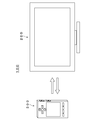
- FIG. 3 is an external view of the operation device 300 on the remote control surface side.
- FIG. 4 is an external view of the operation device 300 on the keyboard surface side.
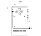
- the operating device 300 has two main surfaces 31 and 32 that are opposed to each other as main surfaces 31 and 32, and the main surfaces 31 and 32 have a size in the biaxial direction. It has a total hexahedron-shaped casing 33 having a sufficiently small size in the axial direction (depth direction) perpendicular to the two axes. Both of the two main surfaces opposite to each other are operation surfaces for the user. That is, one main surface 31 (also referred to as “remote control surface 31”) is provided with a touch pad 34 and keys such as cursor keys 35 as a first operation input unit. The touch pad 34 is disposed in a substantially central region on one main surface 31.
- a keyboard 38 such as a QWERTY keyboard is provided as a second operation input unit on the other main surface 32 (also referred to as “keyboard surface 32”) that is opposed to the remote control surface 31 of the housing 33.
- keyboard surface 32 At least one of the four surfaces (hereinafter referred to as “side surfaces”) other than the remote control surface 31 and the keyboard surface 32 of the housing 33 has, for example, volume adjustment, channel selection, etc.
- a plurality of high keys 37 are provided.
- FIG. 5 is a block diagram illustrating a birdware configuration of the operation device 300.
- the operating device 300 includes a control unit 301, a wireless communication unit 302, a touch pad 34, an acceleration sensor 304, a remote control surface key matrix 305, a side surface key matrix 306, and a keyboard surface key matrix 307.
- the control unit 301 controls the overall control of each block constituting the controller device 300, various arithmetic processes, and data exchange between the blocks.
- the wireless communication unit 302 performs wireless bidirectional signal communication with the information processing apparatus 200.
- a wireless communication system for example, an IR (infrared) system, an RF system such as RF4CE (Radio Frequency for Consumer Electronics) which is an international standard for RF remote controllers for home appliances, a wireless LAN compliant with the IEEE 802.11b standard, and the like. Can be mentioned.
- the touch pad 34 is a device that detects the coordinates of the position touched by the user.
- the touch pad 34 is composed of, for example, a capacitive sensor, a resistive film type touch sensor, or the like.
- the acceleration sensor 304 is a sensor that detects acceleration in the directions of three axes (X axis, Y axis, and Z axis). A detection signal from the acceleration sensor 304 is supplied to the control unit 301 and processed as information for detecting the attitude of the controller device 300.
- means for detecting the attitude of the controller device 300 includes a gyro sensor that detects an angle with respect to the direction of gravity in addition to the acceleration sensor 304.
- a peripheral image viewed from the operation device 300 is captured by a camera (not shown), and the captured image is analyzed by the control unit 301 in the operation device 300 or the CPU 201 in the information processing device 200. There is also a method for detecting the posture.
- the remote control surface key matrix 305 detects an operation on a key such as the cursor key 35 provided on the remote control surface 31 and notifies the control unit 301 of the operation.
- the side key matrix 306 detects an operation on the key 37 provided on the side surface 36 of the housing 33 and notifies the control unit 301 of the operation.
- the keyboard surface 32 key matrix 307 detects an operation on the keyboard 38 and notifies the control unit 301 of the operation.
- the control unit 301 of the operating device 300 performs the following control based on a preinstalled touchpad detection information conversion program.
- the control unit 301 of the operation device 300 determines the operation posture of the operation device 300 based on the detection result obtained by the acceleration sensor 304 (determination unit).
- a vertical orientation (hereinafter referred to as “touch pad operation posture”) with the remote control surface 31 facing the user (see FIG. 6).
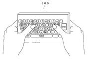
- a posture in which the keyboard surface 32 faces sideways (hereinafter referred to as “keyboard operation posture”).
- keyboard operation posture The reason why it is used horizontally is that the keyboard layout of a keyboard 38 such as a QWERTY keyboard is horizontally long.
- the user holds both ends of the operation device 300 with both hands and performs key input using the fingers of both hands.
- the user can operate the touch pad 34 by turning his / her finger to the back side (remote control surface 31 side).
- Examples of a method for determining the operation posture of the controller device 300 based on the detection result obtained by the acceleration sensor 304 include the following. 1. Based on the output of the acceleration sensor 304, the control unit 301 determines which of the remote control surface 31 and the keyboard surface 32 is more oriented in the direction of gravity. When the control unit 301 determines that the remote control surface 31 is directed more in the direction of gravity, the control unit 301 determines that the keyboard operation posture is set, and determines that the keyboard surface 32 is directed more in the direction of gravity. If it is determined, it is determined that the touch pad operation posture is set. 2. It is determined which of the longitudinal direction and the short direction of the operating device 300 is more directed in the direction of gravity.
- the control unit 301 determines that the longitudinal direction of the operation device 300 is more directed to the gravitational direction, the control unit 301 determines that the touch pad operation posture is present, and the shorter direction is more directed to the gravitational direction. If it is determined that the keyboard is in the keyboard operation position, it is determined. 3.
- the above two determination methods are used in combination. That is, when the control unit 301 determines that the remote control surface 31 is directed more in the direction of gravity and the shorter direction is directed more in the direction of gravity, the control unit 301 determines that the keyboard operation posture is set. In addition, when it is determined that the keyboard surface 32 is directed more in the direction of gravity and the longitudinal direction is directed more in the direction of gravity, the control unit 301 determines that the touch pad operation posture is set. Ignore otherwise.
- the control unit 301 determines the touch pad operation posture, the output information of the touch pad 34 is validated as it is.
- the direction and the vertical direction are the Y-axis directions.
- the coordinate system of the coordinate detection space of the touch pad 34 and the coordinate system seen through the coordinate detection space 34S of the touch pad 34 from the keyboard surface 32 are mirror surfaces when in the keyboard operation posture. Symmetrical and 180-degree rotational symmetry. Therefore, when the keyboard operation posture is determined, the control unit 301 coordinates (X, Y) detected by the touch pad 34 in the coordinate system (X, Y) seen through the coordinate detection space 34S of the touch pad 34 from the keyboard surface 32. ', Y') by the following calculation (conversion unit).
- ⁇ is the length of the touch pad 34 in the Y-axis direction
- ⁇ is the length of the touch pad 34 in the X-axis direction.
- the touch pad 34 has the same length in the X-axis direction and the Y-axis direction.
- these calculation formulas are used according to the aspect ratio in the above conversion.
- the values of Y and X adopted in the above may be adjusted by scale conversion, center correction, or both.
- the keyboard operation posture is obtained.
- the operation of the touch pad 34 can be performed as per the user's coordinate system.
- the control unit 301 stops the operation input unit provided on the back surface as viewed from the user in accordance with the operation posture determined based on the output of the acceleration sensor 304.
- the control is performed so as to be in the state.
- the control unit 301 performs control so that the detection of the operation of the key such as the cursor key 35 provided on the remote control surface 31 is stopped.
- the operation device 300A of the present modification is different from the above-described embodiment in two basic postures during operation.
- 1a A posture in which the remote control surface 31 faces sideways (hereinafter referred to as a “second touchpad operation posture”) (see FIG. 11).
- 2b A posture in which the keyboard surface 32 faces sideways (see FIG. 12) (hereinafter referred to as “keyboard operation posture”).
- This keyboard operation posture is the same as that in the above embodiment.
- the control unit 301 validates the output information of the touch pad 34 as it is.
- the coordinate system of the touch pad 34 and the coordinate system seen through the coordinate detection space 34S of the touch pad 34 from the keyboard surface 32 are mirror-symmetrical. Become. Therefore, the control unit 301 of the operation device 300A has a coordinate system in which the coordinates (X, Y) detected by the touch pad 34 are seen through the coordinate detection space 34S of the touch pad 34 from the keyboard surface 32 when the keyboard operation posture is determined. Are converted to the coordinates (X ′, Y ′) by the following calculation.
- ⁇ is the length of the touch pad 34 in the Y-axis direction.
- the operation posture of the operation device 300A is determined as follows. 1. Based on the output of the acceleration sensor 304, the control unit 301 determines which of the remote control surface 31 and the keyboard surface 32 is more oriented in the direction of gravity. When the control unit 301 determines that the remote control surface 31 is directed more in the direction of gravity, the control unit 301 determines that the keyboard operation posture is set, and determines that the keyboard surface 32 is directed more in the direction of gravity. If it is determined, it is determined that the touch pad operation posture is set.
- the coordinates in the coordinate system of the touch pad 34 detected in response to the operation of the touch pad 34 in the keyboard operation posture in this way are the coordinates in the coordinate system seen through the coordinate detection space 34S of the touch pad 34 from the keyboard surface 32. Therefore, the operation of the touch pad 34 in the keyboard operation posture can be performed as per the user's coordinate system.
- the movement information (x, y) detected by the touch pad 34 is converted into movement information (x ′, y ′) in a coordinate system seen through the coordinate detection space 34S of the touch pad 34 from the keyboard surface 32.
- the calculation formula is as follows.
- the touch pad 34 has the same length in the X-axis direction and the Y-axis direction.
- these calculation formulas are used according to the aspect ratio in the above conversion.
- the values of x and y adopted in the above may be adjusted by scale conversion, center correction, or both.
- Control such as coordinate conversion and key detection stop in the above-described embodiments and modifications is not performed by the control unit 301 of the operation device 300, but the CPU 201 of the information processing device 200 that is the control target of the operation device 300 (FIG. 2). ).
- the operation device 300 and the information processing device 200 enable relatively high-speed wireless communication such as an RF signal or a wireless LAN, a practically sufficient real-time property can be obtained even by control by the CPU 201 of the information processing device 200. It is done.
- the attitude of the controller device 300 is determined using the acceleration sensor 304.
- the controller device 300 determines the attitude of the controller device 300 based on an image captured by a camera provided in the controller device 300. You may do it.
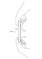
- FIGS. 13 and 14 are diagrams illustrating a state in which the attitude of the operation device 300B is determined based on an image captured by a camera provided in the operation device 300B.
- the lens 41 of the camera is provided on either the remote control surface 31 or the keyboard surface 32. In the illustrated example, it is assumed that the lens 41 of the camera is provided on the remote control surface side.
- the control unit 301 of the operating device 300B recognizes the user 51 by pattern matching of the face image of the user 51 captured by the camera. When the recognized user 51 coincides with a user registered in advance, the control unit 301 determines that the controller device 300B is in a posture with the remote control surface 31 facing the user 51 (see FIG. 13). Conversely, when the registered user's face is not recognized, the control unit 301 determines that the controller device 300B is in a posture with the keyboard surface 32 facing the user 51 (see FIG. 14).
- the determination of the attitude of the operating device 300B and the determination result of the horizontal / vertical orientation of the operating device 300B by the acceleration sensor 304 may be combined to obtain the final determination result of the operating device 300B.
- the attitude of the controller device 300B can be determined with higher accuracy.
- the controller device 300B may be operated at a position lower than the eye height of the user 51 or may be operated at a position higher than the eye height of the user 51.
- the method of the modified example 3 in any state, it is possible to accurately determine the touch pad operation posture and the keyboard operation posture.
- ⁇ Modification 5> In a state where a detector such as a finger is detected on the touch pad 34, the determination of the touch pad operation posture and the keyboard operation posture based on the captured image of the camera and the output of the acceleration sensor 304 may be invalidated.
- FIG. 15 is a diagram showing the state of this control.
- the control unit 301 When the posture of the operation device 300C is changed from the touch pad operation posture (state 1) so that the remote control surface 31 is directed more in the direction of gravity (state 2), the control unit 301 operates based on the output of the acceleration sensor 304. It is determined that the posture of the device 300C has changed to the keyboard operation posture.
- the control unit 301 outputs the captured image of the camera or the output of the acceleration sensor 304.
- the determination of the touchpad operation posture and the keyboard operation posture based on is invalidated. Accordingly, the control is performed on the assumption that the posture of the operation device 300C remains the touch pad operation posture.
- the touch pad operation posture and the keyboard operation posture based on the captured image obtained from the camera and the output of the acceleration sensor 304 are displayed.
- the determination may be invalidated.
- the touch pad operation posture and the keyboard operation posture based on the output of the acceleration sensor 304 are changed. The determination may be invalidated and the control with the touch pad operation posture may be performed.
- the touch pad operation posture and the keyboard operation posture based on the output of the acceleration sensor 304 are changed. The determination may be invalidated and the control with the keyboard operation posture may be performed.
- this technique can also take the following structures.
- a housing having two surfaces opposite to each other as a first surface and a second surface;
- a first operation input unit that includes a detection unit that is provided on the first surface and detects a user operation on a predetermined coordinate detection space on the first surface;
- a second operation input unit provided on the second surface;
- a determination unit that determines an attitude of the housing when a user operation is performed on the coordinate detection space of the detection unit from the second surface side;
- An operation device comprising: a conversion unit that converts information detected by the detection unit into information of a coordinate system viewed through the coordinate detection space from the second surface side when the posture is determined.
- the detection unit detects coordinates instructed by a user with respect to the coordinate detection space;
- the conversion unit has coordinates detected by the detection unit as (X, Y), detection coordinates in a coordinate system seen through the coordinate detection space from the second surface side (X ′, Y ′), and
- the length of the coordinate detection space in the Y-axis direction is ⁇
- the length of the coordinate detection space in the X-axis direction is ⁇
- the operating device includes one or more key operation units together with the detection unit, An operating device further comprising a control unit that stops detecting operation of the key operating unit when the posture is determined.
- the operating device is an operating device that stops the determination of the posture when information is output from the detection unit.
- the operating device is an operating device which makes determination of the said attitude
- the operating device any one of (1) to (4),
- the determination unit An imaging unit capable of photographing the front side of one of the first surface and the second surface;
- the controller is an operation device that determines the posture based on an image captured by the imaging unit.
- the operating device The detection unit detects coordinates instructed by a user with respect to the coordinate detection space;
- the converter is Detection coordinates obtained in the coordinate system of the coordinate detection unit are (X, Y), detection coordinates in the coordinate system seen through the space from the second surface side are (X ′, Y ′), and the coordinate detection unit
- the operating device includes one or more key operation units together with the detection unit, An operating device further comprising a control unit that stops detecting operation of the key operating unit when the posture is determined.
- the operating device is an operating device that stops the determination of the posture when information is output from the detection unit.
- the operating device is an operating device which makes determination of the said attitude
- the operating device according to any one of (7) to (10),
- the determination unit An imaging unit capable of photographing the front side of one of the first surface and the second surface;
- the controller is an operation device that determines the posture based on an image captured by the imaging unit.
- the detection unit detects movement information by a user operation with respect to the coordinate detection space,
- the converter is
- the movement information detected by the coordinate detection unit is (x, y)
- the movement information in the coordinate system seen through the coordinate detection space from the second surface side is (x ′, y ′).
- the operating device includes one or more key operation units together with the detection unit, An operating device further comprising a control unit that stops detecting operation of the key operating unit when the posture is determined.
- the operating device includes one or more key operation units together with the detection unit, An operating device further comprising a control unit that stops detecting operation of the key operating unit when the posture is determined.
- the operating device includes one or more key operation units together with the detection unit, An operating device further comprising a control unit that stops detecting operation of the key operating unit when the posture is determined.
- the operating device is an operating device that stops the determination of the posture when information is output from the detection unit.
- the operating device is an operating device which makes determination of the said attitude
- the operating device according to any one of (12) to (15),
- the determination unit An imaging unit capable of photographing the front side of one of the first surface and the second surface;
- the controller is an operation device that determines the posture based on an image captured by the imaging unit.
- the operating device (1),
- the detection unit detects movement information by a user operation with respect to the coordinate detection space,
- the converter is
- the movement information obtained in the coordinate system of the coordinate detection unit is (x, y)
- the movement information in the coordinate system seen through the coordinate detection space from the second surface side is (x ′, y ′)
- Operation device that performs conversion using the following formula.
- the operating device includes one or more key operation units together with the detection unit, An operating device further comprising a control unit that stops detecting operation of the key operating unit when the posture is determined.
- the determination unit is an operating device that stops the determination of the posture when information is output from the detection unit.
- the operating device is an operating device which makes determination of the said attitude
- the determination unit An imaging unit capable of photographing the front side of one of the first surface and the second surface;
- the controller is an operation device that determines the posture based on an image captured by the imaging unit.
Landscapes
- Engineering & Computer Science (AREA)
- Theoretical Computer Science (AREA)
- Human Computer Interaction (AREA)
- Computer Hardware Design (AREA)
- Multimedia (AREA)
- Signal Processing (AREA)
- General Engineering & Computer Science (AREA)
- Physics & Mathematics (AREA)
- General Physics & Mathematics (AREA)
- Position Input By Displaying (AREA)
- Selective Calling Equipment (AREA)
- Details Of Television Systems (AREA)
Priority Applications (4)
| Application Number | Priority Date | Filing Date | Title |
|---|---|---|---|
| CN201280040767.6A CN103765365B (zh) | 2011-08-31 | 2012-08-24 | 操作装置、其信息处理方法和信息处理装置 |
| US14/238,642 US8830406B2 (en) | 2011-08-31 | 2012-08-24 | Operation apparatus, information processing method therefor, and information processing apparatus |
| BR112014004124A BR112014004124A2 (pt) | 2011-08-31 | 2012-08-24 | aparelho de operação, método de processamento de informação para um aparelho de operação, e, aparelho de processamento de informação |
| RU2014106485A RU2621183C2 (ru) | 2011-08-31 | 2012-08-24 | Устройство оперирования, способ обработки информации в нем и устройство обработки информации |
Applications Claiming Priority (2)
| Application Number | Priority Date | Filing Date | Title |
|---|---|---|---|
| JP2011-189439 | 2011-08-31 | ||
| JP2011189439A JP5891659B2 (ja) | 2011-08-31 | 2011-08-31 | 操作装置、その情報処理方法及び情報処理装置 |
Publications (1)
| Publication Number | Publication Date |
|---|---|
| WO2013031158A1 true WO2013031158A1 (ja) | 2013-03-07 |
Family
ID=47755688
Family Applications (1)
| Application Number | Title | Priority Date | Filing Date |
|---|---|---|---|
| PCT/JP2012/005311 Ceased WO2013031158A1 (ja) | 2011-08-31 | 2012-08-24 | 操作装置、その情報処理方法及び情報処理装置 |
Country Status (6)
| Country | Link |
|---|---|
| US (1) | US8830406B2 (enExample) |
| JP (1) | JP5891659B2 (enExample) |
| CN (1) | CN103765365B (enExample) |
| BR (1) | BR112014004124A2 (enExample) |
| RU (1) | RU2621183C2 (enExample) |
| WO (1) | WO2013031158A1 (enExample) |
Families Citing this family (4)
| Publication number | Priority date | Publication date | Assignee | Title |
|---|---|---|---|---|
| JP6323761B2 (ja) * | 2015-03-27 | 2018-05-16 | パナソニックIpマネジメント株式会社 | 遠隔制御システム及び電子機器 |
| US9779710B2 (en) * | 2015-04-17 | 2017-10-03 | Samsung Electronics Co., Ltd. | Electronic apparatus and control method thereof |
| US9781468B2 (en) | 2015-08-25 | 2017-10-03 | Echostar Technologies L.L.C. | Dynamic scaling of touchpad/UI grid size relationship within a user interface |
| US9826187B2 (en) * | 2015-08-25 | 2017-11-21 | Echostar Technologies L.L.C. | Combined absolute/relative touchpad navigation |
Citations (5)
| Publication number | Priority date | Publication date | Assignee | Title |
|---|---|---|---|---|
| JPH04148412A (ja) * | 1990-10-12 | 1992-05-21 | Sharp Corp | タッチパネルを有する電子入力装置 |
| JP2001051799A (ja) * | 1999-05-28 | 2001-02-23 | Sony Corp | 表示装置及びこれを使用したカメラ |
| JP2001147775A (ja) * | 1999-11-24 | 2001-05-29 | Casio Comput Co Ltd | 携帯端末装置及びそのプログラムを記憶した記憶媒体 |
| WO2005010740A1 (ja) * | 2003-07-28 | 2005-02-03 | Nec Corporation | 携帯情報端末 |
| JP2009187290A (ja) * | 2008-02-06 | 2009-08-20 | Yamaha Corp | タッチパネル付制御装置およびプログラム |
Family Cites Families (10)
| Publication number | Priority date | Publication date | Assignee | Title |
|---|---|---|---|---|
| JPH0689634A (ja) | 1992-09-08 | 1994-03-29 | Sony Corp | 入力装置 |
| KR100748859B1 (ko) | 1999-05-28 | 2007-08-13 | 소니 가부시끼 가이샤 | 촬상 장치 |
| JP2002077357A (ja) * | 2000-06-13 | 2002-03-15 | Matsushita Electric Ind Co Ltd | 電子機器 |
| JP3852368B2 (ja) * | 2002-05-16 | 2006-11-29 | ソニー株式会社 | 入力方法及びデータ処理装置 |
| US7259710B2 (en) * | 2002-08-07 | 2007-08-21 | Canon Information Systems Research Australia Pty Ltd | User input device |
| JP2008077845A (ja) * | 2006-09-19 | 2008-04-03 | Funai Electric Co Ltd | リモートコントローラ |
| US20100277420A1 (en) * | 2009-04-30 | 2010-11-04 | Motorola, Inc. | Hand Held Electronic Device and Method of Performing a Dual Sided Gesture |
| JP2011034294A (ja) | 2009-07-31 | 2011-02-17 | Sony Corp | 情報処理装置、操作端末、情報処理システムおよび情報処理システムによる情報処理方法 |
| JP5437023B2 (ja) * | 2009-11-02 | 2014-03-12 | 株式会社ソニー・コンピュータエンタテインメント | 操作入力装置 |
| KR101275314B1 (ko) * | 2011-05-11 | 2013-06-17 | 도시바삼성스토리지테크놀러지코리아 주식회사 | 리모트 컨트롤러와, 이를 이용한 제어 방법 및 제어 시스템 |
-
2011
- 2011-08-31 JP JP2011189439A patent/JP5891659B2/ja active Active
-
2012
- 2012-08-24 RU RU2014106485A patent/RU2621183C2/ru not_active IP Right Cessation
- 2012-08-24 CN CN201280040767.6A patent/CN103765365B/zh active Active
- 2012-08-24 BR BR112014004124A patent/BR112014004124A2/pt not_active Application Discontinuation
- 2012-08-24 WO PCT/JP2012/005311 patent/WO2013031158A1/ja not_active Ceased
- 2012-08-24 US US14/238,642 patent/US8830406B2/en active Active
Patent Citations (5)
| Publication number | Priority date | Publication date | Assignee | Title |
|---|---|---|---|---|
| JPH04148412A (ja) * | 1990-10-12 | 1992-05-21 | Sharp Corp | タッチパネルを有する電子入力装置 |
| JP2001051799A (ja) * | 1999-05-28 | 2001-02-23 | Sony Corp | 表示装置及びこれを使用したカメラ |
| JP2001147775A (ja) * | 1999-11-24 | 2001-05-29 | Casio Comput Co Ltd | 携帯端末装置及びそのプログラムを記憶した記憶媒体 |
| WO2005010740A1 (ja) * | 2003-07-28 | 2005-02-03 | Nec Corporation | 携帯情報端末 |
| JP2009187290A (ja) * | 2008-02-06 | 2009-08-20 | Yamaha Corp | タッチパネル付制御装置およびプログラム |
Also Published As
| Publication number | Publication date |
|---|---|
| CN103765365B (zh) | 2017-10-13 |
| BR112014004124A2 (pt) | 2017-04-04 |
| US20140192269A1 (en) | 2014-07-10 |
| JP2013050907A (ja) | 2013-03-14 |
| JP5891659B2 (ja) | 2016-03-23 |
| RU2621183C2 (ru) | 2017-05-31 |
| US8830406B2 (en) | 2014-09-09 |
| RU2014106485A (ru) | 2015-08-27 |
| CN103765365A (zh) | 2014-04-30 |
Similar Documents
| Publication | Publication Date | Title |
|---|---|---|
| US9414125B2 (en) | Remote control device | |
| KR101711828B1 (ko) | 영상표시장치 및 그 동작방법 | |
| CN110320976B (zh) | 用户终端装置及其显示方法 | |
| US8689145B2 (en) | 3D remote control system employing absolute and relative position detection | |
| CN103530032B (zh) | 移动终端、图像显示装置及使用其的用户接口提供方法 | |
| CN103513894B (zh) | 显示设备、远程控制设备及其控制方法 | |
| CN105980955B (zh) | 用户终端装置及其显示方法 | |
| EP2677741A1 (en) | Remote control apparatus and control method thereof | |
| US20130106700A1 (en) | Electronic apparatus and input method | |
| CN109857306B (zh) | 截屏方法及终端设备 | |
| EP2297675A1 (en) | 3d pointer mapping | |
| KR101821781B1 (ko) | 핸드헬드 디바이스의 포워드 포인팅 방향의 결정 | |
| KR20170124811A (ko) | 영상 표시 장치 및 그 동작방법 | |
| JP5891659B2 (ja) | 操作装置、その情報処理方法及び情報処理装置 | |
| CN111176522B (zh) | 一种解锁方法及电子设备 | |
| US20130201157A1 (en) | User interface device and method of providing user interface | |
| CN109446765B (zh) | 一种屏幕解锁方法及终端设备 | |
| CN107239204A (zh) | 显示设备和显示方法 | |
| JP2015158928A (ja) | 画像提供機器、制御方法、表示システム、表示装置、およびテレビジョン受像機 | |
| KR101424562B1 (ko) | 공간 인식 장치, 이의 동작 방법 및 이를 포함하는 시스템 | |
| CN203054768U (zh) | 指标输入装置 | |
| KR20130123679A (ko) | 화상회의장치, 및 그 동작방법 | |
| WO2014157360A1 (ja) | 外部機器、制御方法、表示システム、表示装置、およびテレビジョン受像機 |
Legal Events
| Date | Code | Title | Description |
|---|---|---|---|
| 121 | Ep: the epo has been informed by wipo that ep was designated in this application |
Ref document number: 12826912 Country of ref document: EP Kind code of ref document: A1 |
|
| WWE | Wipo information: entry into national phase |
Ref document number: 14238642 Country of ref document: US |
|
| ENP | Entry into the national phase |
Ref document number: 2014106485 Country of ref document: RU Kind code of ref document: A |
|
| NENP | Non-entry into the national phase |
Ref country code: DE |
|
| 122 | Ep: pct application non-entry in european phase |
Ref document number: 12826912 Country of ref document: EP Kind code of ref document: A1 |
|
| REG | Reference to national code |
Ref country code: BR Ref legal event code: B01A Ref document number: 112014004124 Country of ref document: BR |
|
| ENP | Entry into the national phase |
Ref document number: 112014004124 Country of ref document: BR Kind code of ref document: A2 Effective date: 20140221 |