WO2013022018A1 - バルブ、燃料電池システム - Google Patents
バルブ、燃料電池システム Download PDFInfo
- Publication number
- WO2013022018A1 WO2013022018A1 PCT/JP2012/070168 JP2012070168W WO2013022018A1 WO 2013022018 A1 WO2013022018 A1 WO 2013022018A1 JP 2012070168 W JP2012070168 W JP 2012070168W WO 2013022018 A1 WO2013022018 A1 WO 2013022018A1
- Authority
- WO
- WIPO (PCT)
- Prior art keywords
- valve
- pressure receiving
- diaphragm
- receiving plate
- inflow hole
- Prior art date
- Legal status (The legal status is an assumption and is not a legal conclusion. Google has not performed a legal analysis and makes no representation as to the accuracy of the status listed.)
- Ceased
Links
Images


Classifications
-
- G—PHYSICS
- G05—CONTROLLING; REGULATING
- G05D—SYSTEMS FOR CONTROLLING OR REGULATING NON-ELECTRIC VARIABLES
- G05D16/00—Control of fluid pressure
- G05D16/04—Control of fluid pressure without auxiliary power
- G05D16/06—Control of fluid pressure without auxiliary power the sensing element being a flexible membrane, yielding to pressure, e.g. diaphragm, bellows, capsule
- G05D16/063—Control of fluid pressure without auxiliary power the sensing element being a flexible membrane, yielding to pressure, e.g. diaphragm, bellows, capsule the sensing element being a membrane
- G05D16/0644—Control of fluid pressure without auxiliary power the sensing element being a flexible membrane, yielding to pressure, e.g. diaphragm, bellows, capsule the sensing element being a membrane the membrane acting directly on the obturator
- G05D16/0647—Control of fluid pressure without auxiliary power the sensing element being a flexible membrane, yielding to pressure, e.g. diaphragm, bellows, capsule the sensing element being a membrane the membrane acting directly on the obturator using one membrane without spring
-
- H—ELECTRICITY
- H01—ELECTRIC ELEMENTS
- H01M—PROCESSES OR MEANS, e.g. BATTERIES, FOR THE DIRECT CONVERSION OF CHEMICAL ENERGY INTO ELECTRICAL ENERGY
- H01M8/00—Fuel cells; Manufacture thereof
- H01M8/04—Auxiliary arrangements, e.g. for control of pressure or for circulation of fluids
- H01M8/04082—Arrangements for control of reactant parameters, e.g. pressure or concentration
- H01M8/04089—Arrangements for control of reactant parameters, e.g. pressure or concentration of gaseous reactants
-
- Y—GENERAL TAGGING OF NEW TECHNOLOGICAL DEVELOPMENTS; GENERAL TAGGING OF CROSS-SECTIONAL TECHNOLOGIES SPANNING OVER SEVERAL SECTIONS OF THE IPC; TECHNICAL SUBJECTS COVERED BY FORMER USPC CROSS-REFERENCE ART COLLECTIONS [XRACs] AND DIGESTS
- Y02—TECHNOLOGIES OR APPLICATIONS FOR MITIGATION OR ADAPTATION AGAINST CLIMATE CHANGE
- Y02E—REDUCTION OF GREENHOUSE GAS [GHG] EMISSIONS, RELATED TO ENERGY GENERATION, TRANSMISSION OR DISTRIBUTION
- Y02E60/00—Enabling technologies; Technologies with a potential or indirect contribution to GHG emissions mitigation
- Y02E60/30—Hydrogen technology
- Y02E60/50—Fuel cells
Definitions
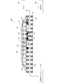
- FIG. 1 shows a cross-sectional view of a pressure control valve disclosed in Patent Document 1.
- This pressure control valve includes a diaphragm 1 serving as a movable portion, a transmission mechanism 2, a valve seat portion 3, a valve body portion 4, and a support portion 5.
- the valve seat part 3, the valve body part 4, and the support part 5 form a valve part.
- the valve body portion 4 is supported around the support portion 5.
- the support part 5 is formed of an elastic beam.
- each of these members is composed of a plate-like member, and the pressure control valve is formed by joining the members.
- the inventor of the present application provides a valve between the fuel cartridge and the pump, which is a valve that stops the forward flow when the high-pressure liquid fuel is added, and is opened and closed by the pressure of the pump. We used the following policy.
- an object of the present invention is to provide a valve that blocks excessive flow in the forward direction of a fluid that can suppress the deflection of the diaphragm without reducing the amount of displacement of the diaphragm, and a fuel cell system including the valve. To do.
- valve housing having a fluid inlet hole and the fluid outlet hole;
- a diaphragm in which a peripheral portion is fixed to the valve housing to form a valve chamber together with the valve housing, and a central portion inside the peripheral portion is displaced by the pressure of the fluid in the valve chamber;
- a flat plate-shaped pressure receiving portion having a first surface and a second surface facing the first surface, and a columnar pusher portion connected to the first surface of the pressure receiving portion, The area of the second surface of the pressure receiving portion is larger than the area of the connection surface of the pusher portion with the pressure receiving portion, and the second surface of the pressure receiving portion is not on the surface of the diaphragm on the valve housing side.
- a pressure receiving plate disposed in the valve chamber so as to face each other in an adhesive state;
- a valve body that is disposed in the inflow hole so as to face the pusher portion and brings the inflow hole and the valve chamber into a connected state from a shut-off state in accordance with the displacement of the pressure receiving plate due to the displacement of the diaphragm. .
- the pressure receiving plate is disposed between the diaphragm and the bottom surface of the valve chamber, it is possible to suppress the deflection of the diaphragm caused by the displacement of the diaphragm. Therefore, even if the diaphragm is formed of a material having low rigidity, at least a pressure receiving area corresponding to the area of the pressure receiving plate facing the diaphragm can be secured.
- the pressure receiving plate is disposed in the valve chamber so as to face the surface of the diaphragm on the valve housing side in a non-adhered state, the pressure receiving plate is displaced toward the valve body side with the displacement of the central portion of the diaphragm without disturbing the deformation of the diaphragm. To do. Therefore, the amount of diaphragm displacement is not reduced.
- the pressure receiving plate has a higher rigidity than the diaphragm.
- the bending of the diaphragm can be further suppressed.
- the said pressure receiving plate is arrange
- the valve in this configuration can be manufactured without using a bonding process because it is not necessary to bond the pressure receiving plate to the diaphragm and the valve body. Therefore, according to this structure, it can manufacture at low cost. Further, since the valve in this configuration can be manufactured without using an adhesion process, the adhesive does not elute into the fluid.
- the pressure receiving portion of the pressure receiving plate is opposed to the valve housing when the valve body places the inflow hole and the valve chamber in a connected state due to the displacement of the pressure receiving plate due to the displacement of the diaphragm. It is preferable that a protruding portion and a flow path for allowing the fluid to pass from the inside to the outside of the protruding portion are formed around the inflow hole on the bottom surface of the valve chamber facing the pressure receiving plate. .
- the pressure receiving plate when the inflow hole and the valve chamber are connected, the pressure receiving plate can be prevented from blocking the inflow hole of the valve housing.
- the inflow hole of the valve housing has a distance from the inflow hole to a portion facing the inflow hole in the diaphragm from a distance from the outflow hole to a portion facing the outflow hole in the diaphragm. It is preferable that the length is also shortened.
- the material of the diaphragm is preferably a resin.
- the pressure receiving plate is preferably made of resin.
- FIG. 1 is a system configuration diagram of a fuel cell system including a valve 101 according to an embodiment of the present invention. It is a disassembled perspective view explaining the structure of the valve
- FIG. 4A is a top view of the cap part 110 provided in the valve 101 of FIG.
- FIG. 4B is a bottom view of the valve housing 130 provided in the valve 101 of FIG.
- FIG. 5 is a cross-sectional view taken along line SS in FIG.
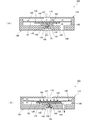
- FIG. 6A is a schematic cross-sectional view of the valve 101 according to the embodiment of the present invention when the valve is closed.
- FIG. 4A is a top view of the cap part 110 provided in the valve 101 of FIG.
- FIG. 4B is a bottom view of the valve housing 130 provided in the valve 101 of FIG.
- FIG. 5 is a cross-sectional view taken along line SS in FIG.
- FIG. 6A is a schematic cross-sectional view of the valve 101 according to the embodiment of the present invention when
- valve 101 according to the embodiment of the present invention will be described.
- the valve housing 130 has a protruding portion 144 with which the pressure receiving plate 125 abuts when the valve portion 150 connects the inflow hole 143 and the valve chamber 140, and methanol. Is formed around the inflow hole 143 on the bottom surface 141 of the valve chamber 140 facing the diaphragm 120.
- valve body portion 151 When the pressure in the valve chamber 140 decreases due to the suction of methanol by the pump 103, the valve body portion 151 is separated from the valve seat 148 by the diaphragm 120 descending and the pusher portion 127 of the pressure receiving plate 125 abutting and being pushed down.
- the inflow hole 143 and the valve chamber 140 are connected. As a result, the inflow hole 143 and the hole portion 153 communicate with each other, and methanol flows into the valve chamber 140.
- the pressure receiving plate 125 is formed in, for example, a disk shape, and includes a pressure receiving portion 126 having a first surface and a second surface facing the first surface, and a first pressure on the valve housing 130 side in the pressure receiving portion 126. It has a pusher portion 127 that protrudes from the central portion of the surface and is formed in a columnar shape, for example.
- the pusher portion 127 of the pressure receiving plate 125 is placed on the valve portion 150. However, since the urging force Fs of the valve portion 150 is a force that exceeds the weight of the pressure receiving plate 125, the pusher portion 127 depends on the weight of the pressure receiving plate 125.
- the inflow hole 143 and the valve chamber 140 are not connected.
- the valve 101 is configured so that the valve unit 150 automatically opens and closes using the pressure difference when the fluid pressure reaches the set pressure. More specifically, the pressure of the atmosphere above the diaphragm 120 is P0, the primary pressure upstream of the valve is P1, and the pressure downstream of the valve is P2, and the area of the valve body 151 (here, the valve body 151 includes a ring-shaped valve). Since the protrusion 155 is formed, the area determined by the diameter of the region surrounded by the valve protrusion 155 is S1, and the area of the diaphragm 120 in contact with the valve chamber 140 (hereinafter referred to as “pressure receiving area”) is S2. A force by which the valve body 151 urges the valve seat 148 is defined as Fs.
- valve 101 when the pressure in the valve chamber 140 decreases due to the suction of methanol by the pump 103, the central portion 122 of the diaphragm 120 is displaced and the pressure receiving portion 126 of the pressure receiving plate 125 is pushed down, and the pusher portion of the pressure receiving plate 125 is pressed. 127 is displaced and presses down the valve body 151 of the valve 150 (see FIG. 6B). Thereby, the inflow hole 143 and the valve chamber 140 are connected, and methanol flows into the valve chamber 140 from the inflow hole 143.
- the pressure receiving plate 125 is disposed between the diaphragm 120 and the bottom surface 141 of the valve chamber 140 as shown in FIGS. 5 and 6, the bending of the diaphragm 120 can be suppressed. Therefore, even when the diaphragm 120 is formed of a material having low rigidity, at least a pressure receiving area S2 corresponding to the area of the pressure receiving plate 125 (second surface) facing the diaphragm 120 can be secured.
- valve 101 it is possible to suppress the pressure receiving area S2 of the diaphragm 120 from decreasing. Therefore, the diaphragm 120 can be prevented from sticking to the bottom surface 141 of the valve chamber 140.
- the inflow hole 143 of the valve housing 130 has a distance A (that is, the shortest distance between the inflow hole 143 and the diaphragm 120) from the inflow hole 143 to a portion of the diaphragm 120 facing the inflow hole 143.
- A that is, the shortest distance between the inflow hole 143 and the diaphragm 120
- the pressure receiving plate 125 first comes into contact with the protruding portion 144 located around the inflow hole 143 on the bottom surface of the valve chamber 140. Therefore, according to the valve 101 of this embodiment, the pressure receiving plate 125 and the diaphragm 120 can be prevented from closing the outflow hole 149 of the valve housing 130.
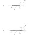
- FIG. 7A is a cross-sectional view when the inflow hole 143 and the valve chamber 140 of the diaphragm 120 and the pressure receiving plate 125 provided in the valve 101 according to the embodiment of the present invention are in a shut-off state, that is, when the valve is closed. is there.
- FIG. 7B is a cross-sectional view of the diaphragm 120 and the pressure receiving plate 125 provided in the valve 101 according to the embodiment of the present invention when the inflow hole 143 and the valve chamber 140 are connected, that is, when the valve is open. is there.
- FIG. 8A is a cross-sectional view of the diaphragm 120A and the pressure receiving plate 125A provided in the valve 201 according to the modification of the present invention when the valve is closed.
- FIG. 8B is a cross-sectional view of the diaphragm 120 and the pressure receiving plate 125 provided in the valve 201 according to the modification of the present invention when the valve is opened.
- the valve 201 shown in FIG. 8 is different from the valve 101 shown in FIG. 7 in that the diaphragm 120 and the pressure receiving plate 125 are bonded, and the other points are the same.
- valve 101 in this embodiment can be manufactured without using an adhesion process because it is not necessary to bond the pressure receiving plate 125 to the diaphragm 120 and the valve body 151. Therefore, the valve 101 in this embodiment can be manufactured at low cost.
- valve 101 in this embodiment can be manufactured without using an adhesion process, the components of the adhesive do not elute in methanol.
- the parts 141, 144, 145, 148 and the pressure receiving plate 125 in contact with methanol of the valve housing 130 are all made of resin, and the material of the diaphragm 120 and the valve part 150 is also rubber, so that metal ions are contained in methanol. It does not elute. Therefore, in the valve 101 of this embodiment, the DMFC characteristics do not deteriorate due to the elution of adhesive components and metal ions.
Landscapes
- Physics & Mathematics (AREA)
- Engineering & Computer Science (AREA)
- General Chemical & Material Sciences (AREA)
- Manufacturing & Machinery (AREA)
- Sustainable Energy (AREA)
- Chemical & Material Sciences (AREA)
- Chemical Kinetics & Catalysis (AREA)
- Electrochemistry (AREA)
- Life Sciences & Earth Sciences (AREA)
- Sustainable Development (AREA)
- Fluid Mechanics (AREA)
- General Physics & Mathematics (AREA)
- Automation & Control Theory (AREA)
- Safety Valves (AREA)
- Fluid-Driven Valves (AREA)
- Fuel Cell (AREA)
Abstract
ダイヤフラムの変位量を低下させずに、ダイヤフラムの撓みを抑制することができる流体の順方向の過剰な流れを遮断するバルブ、及びこのバルブを備える燃料電池システムを提供する。バルブ(101)は、キャップ部(110)と、ダイヤフラム(120)と、受圧板(125)と、バルブ筐体(130)と、弁部(150)とを備える。受圧板(125)は、第1の面と第1の面に対向する第2の面とを有する受圧部(126)と、受圧部(126)における弁部(150)側の第1の面の中心部分から突出するプッシャー部(127)とを有する。受圧板(125)は、プッシャー部(127)の突出方向の先端が弁体部(151)に非接着状態で当接し、受圧部(126)がダイヤフラム(120)のバルブ筐体(130)側の面に非接着状態で当接するようバルブ室(140)に配置されている。
Description
本発明は、流体の順方向の過剰な流れを遮断するバルブ、及びこのバルブを備える燃料電池システムに関するものである。
小型の燃料電池に用いられるパッシブ駆動の圧力制御弁が特許文献1に開示されている。この圧力制御弁は、流体の圧力が設定圧力になると、圧力差を利用してバルブが自動的に開閉するよう構成されている。
図1に、特許文献1に開示されている圧力制御弁の断面図を示す。この圧力制御弁は、可動部となるダイヤフラム1と、伝達機構2と、弁座部3と、弁体部4と、支持部5とからなる。弁座部3、弁体部4、及び支持部5は、弁部を形成する。弁体部4は支持部5によって周囲に支持されている。支持部5は、弾性を有する梁によって形成されている。ここで、これらの各部材は板状の部材で構成されており、当該圧力制御弁は各部材を接合することにより形成している。
ダイヤフラム1上部の圧力をP0、バルブ上流の1次圧力をP1、バルブ下流の圧力をP2とし、弁体部4の面積をS1、バルブ室8に接するダイヤフラム1の部分の面積(以下、受圧面積と称する。)をS2とする。このとき、圧力の釣り合いから、バルブが開く条件は、(P1-P2)S1<(P0-P2)S2となる。P2がこの条件の圧力より高いとバルブは閉じ、低いとバルブは開く。これによって、P2を一定に保つことができる。
例えば、ダイレクトメタノール型燃料電池(DMFC)においては、燃料カートリッジから発電セルへ液体燃料(メタノール)の輸送を行うポンプを備えている。燃料カートリッジはポンプの上流側に配置されており、発電セルはポンプの下流側に配置されている。ポンプが弁方式である場合、弁によってポンプの下流側からポンプの上流側への流体の流れを遮断する逆止機能を備えている。しかし、ポンプの上流側からポンプの下流側への液体燃料の過剰な流れを遮断する機能、すなわち順止機能は備えていないものが一般的である。
例えば、ダイレクトメタノール型燃料電池システムにおいて、燃料電池システム内に組み込まれる燃料カートリッジが、発熱部品によって高温になることがある。燃料カートリッジが高温になると燃料カートリッジの内部の液体燃料が膨張する。このため、高圧となった液体燃料が燃料カートリッジから吐出されることがある。順止機能を備えていない弁方式のポンプでは、これにより、過剰な量の液体燃料が発電セルに供給され、ポンプの非作動時にも、燃料カートリッジから発電セルへ液体燃料が輸送されてしまう。また、場合によってはポンプを破壊してしまうおそれがある。
このような問題を解消するために、高圧の液体燃料が万が一加わった場合などに、順方向の流れを止めるバルブが求められている。そこで、本願の発明者は、高圧の液体燃料が万が一加わった場合などに、順方向の流れを止めるバルブであって、ポンプの圧力によって開閉が行われるバルブを燃料カートリッジとポンプとの間に設けるという方策を用いた。
しかしながら、特許文献1に記載の圧力制御弁では、ダイヤフラム1の変位量を高めるためにダイヤフラム1を剛性の低い材料(例えばゴム)で形成した場合に、圧力制御弁を駆動させると、ダイヤフラム1が撓み、ダイヤフラム1の周縁部がバルブ室8の底面9に押圧されてしまう。この時、ダイヤフラム1とバルブ室8の底面9との間に隙間がなくなると、弁体部4の押し下げに必要なダイヤフラム1の上記受圧面積S2が小さくなる。この結果、上記右辺(P0-P2)S2の値が小さくなり、最悪の場合には弁体部4を開くことができなくなってしまうという問題がある。
そこで、ダイヤフラム1がバルブ室8の底面9に当接する程のダイヤフラム1の撓みを抑制するために、ダイヤフラム1の厚みを従来よりも厚くして剛性を高める方法も考えられるが、ダイヤフラム1の変位量の低下や、圧力制御弁の小型化が阻害されてしまうという問題がある。
そこで本発明は、ダイヤフラムの変位量を低下させずに、ダイヤフラムの撓みを抑制することができる流体の順方向の過剰な流れを遮断するバルブ、及びこのバルブを備える燃料電池システムの提供を目的とする。
本発明のバルブは、前記課題を解決するために以下の構成を備えている。
(1)流体の流入孔と、前記流体の流出孔とを有するバルブ筐体と、
周縁部が前記バルブ筐体に固定されて前記バルブ筐体とともにバルブ室を構成し、前記バルブ室の前記流体の圧力によって前記周縁部より内側の中央部が変位するダイヤフラムと、
第1の面と前記第1の面に対向する第2の面とを有する平板状の受圧部と、前記受圧部の前記第1の面に接続された柱状のプッシャー部とを有し、前記受圧部の前記第2の面の面積は、前記プッシャー部の前記受圧部との接続面の面積よりも大きく、前記受圧部の前記第2の面が前記ダイヤフラムの前記バルブ筐体側の面に非接着状態で対向するよう前記バルブ室に配置されている受圧板と、
前記プッシャー部に対向して前記流入孔に配置され、前記ダイヤフラムの変位による前記受圧板の変位に伴って、前記流入孔と前記バルブ室とを遮断状態から接続状態にする弁体と、を備える。
周縁部が前記バルブ筐体に固定されて前記バルブ筐体とともにバルブ室を構成し、前記バルブ室の前記流体の圧力によって前記周縁部より内側の中央部が変位するダイヤフラムと、
第1の面と前記第1の面に対向する第2の面とを有する平板状の受圧部と、前記受圧部の前記第1の面に接続された柱状のプッシャー部とを有し、前記受圧部の前記第2の面の面積は、前記プッシャー部の前記受圧部との接続面の面積よりも大きく、前記受圧部の前記第2の面が前記ダイヤフラムの前記バルブ筐体側の面に非接着状態で対向するよう前記バルブ室に配置されている受圧板と、
前記プッシャー部に対向して前記流入孔に配置され、前記ダイヤフラムの変位による前記受圧板の変位に伴って、前記流入孔と前記バルブ室とを遮断状態から接続状態にする弁体と、を備える。
この構成では、バルブ室の圧力が低下した時、ダイヤフラムの中央部がバルブ筐体側に変位して受圧板の受圧部に当接して受圧部を押圧する。これに伴って、受圧板のプッシャー部が変位して弁体に当接して弁体を押圧する。これにより、流入孔とバルブ室とが遮断状態から接続状態になって弁が開き、流体が流入孔からバルブ室へ流入する。
受圧板は、ダイヤフラムとバルブ室の底面との間に配置されているため、ダイヤフラムの変位によって発生するダイヤフラムの撓みを抑制することができる。そのため、仮にダイヤフラムを剛性の低い材料で形成した場合でも、ダイヤフラムに対向する受圧板の面の面積分の受圧面積は少なくとも確保できる。
さらに、受圧板は、ダイヤフラムのバルブ筐体側の面に非接着状態で対向するようバルブ室に配置されているため、ダイヤフラムの変形を妨げずにダイヤフラムの中央部の変位に伴って弁体側へ変位する。そのため、ダイヤフラムの変位量を低下させない。
したがって、この構成によれば、ダイヤフラムの変位量を低下させずに、ダイヤフラムの撓みを抑制することができる。
(2)前記受圧板の剛性は、前記ダイヤフラムの剛性より高いことが好ましい。
この構成によれば、ダイヤフラムの撓みを一層抑制することができる。
(3)前記受圧板は、前記プッシャー部が前記弁体に非接着状態で対向するよう配置されていることが好ましい。
この構成におけるバルブは、受圧板をダイヤフラム及び弁体に接着する必要がないため、接着工程を使用せずに製造できる。そのため、この構成によれば、低コストで製造できる。また、この構成におけるバルブは、接着工程を使用せずに製造できるため、接着剤が流体中に溶出することがない。
(4)前記バルブ筐体には、前記ダイヤフラムの変位による前記受圧板の変位によって前記弁体が前記流入孔と前記バルブ室とを接続状態にしたときに、前記受圧板の前記受圧部が対向する突出部と、当該流体を前記突出部の内側から外側へ通過させる流路と、が、前記受圧板と対向する前記バルブ室の底面上における前記流入孔の周囲に形成されていることが好ましい。
この構成では、流入孔とバルブ室とが接続状態となるとき、受圧板の受圧部が、バルブ室の底面でなく突出部に接触する。さらに、受圧板の受圧部が突出部に接触したとき、流体は突出部の内側から流路を介して突出部の外側へ通過する。
したがって、この構成によれば流入孔とバルブ室とが接続状態のとき、受圧板がバルブ筐体の流入孔を塞ぐことを防ぐことができる。
(5)前記バルブ筐体の前記流入孔は、前記流入孔から前記ダイヤフラムにおける前記流入孔に対向する部分までの距離が、前記流出孔から前記ダイヤフラムにおける前記流出孔に対向する部分までの距離よりも短くなるように形成されていることが好ましい。
この構成では流入孔とバルブ室とが接続状態のとき、受圧板がまず、バルブ室の底面上における流入孔の周囲と当接する。そのため、この構成によれば、受圧板やダイヤフラムがバルブ筐体の流出孔を塞ぐことを抑制できる。
(6)ダイヤフラムがゴムで形成されている場合、ダイヤフラムの変位は大きいものの、ゴム製のダイヤフラムはガス透過性が大きくガス漏れのおそれがあるため、前記ダイヤフラムの材質は樹脂であることが好ましい。
液体を流体としてバルブに使用した場合、液体の表面張力が大きいため、気体を流体としてバルブに使用した場合より大きな流体の流路が必要となるが、この構成のバルブではダイヤフラムの変位量が大きいため、ダイヤフラムの材質が樹脂であっても液体の流路を十分に確保できる。
(7)前記受圧板の材質は樹脂であることが好ましい。
(8)前記流体はメタノールであることが好ましい。
この構成において、接着剤の成分がメタノールに溶出すると、燃料電池の機能を損なう。そのため、上記(1)の構成は、メタノールを流体として使用するバルブにおいて好適である。
また、本発明の燃料電池システムは、前記課題を解決するために以下の構成を備えている。
(9)上記(1)~(8)のいずれかに記載のバルブと、
前記バルブの前記流入孔に接続される燃料貯蔵部と、
前記バルブの前記流出孔に接続されるポンプと、を備える。
前記バルブの前記流入孔に接続される燃料貯蔵部と、
前記バルブの前記流出孔に接続されるポンプと、を備える。
この構成により、上記(1)~(8)のうちいずれかに記載のバルブを用いることで、当該バルブを備える燃料電池システムにおいても同様の効果を奏する。
この発明によれば、ダイヤフラムの変位量を低下させずに、ダイヤフラムの撓みを抑制することができる。
以下、本発明の実施形態に係るバルブ101について説明する。
図2は、本発明の実施形態に係るバルブ101を備える燃料電池システム100のシステム構成図である。燃料電池システム100は、液体燃料であるメタノールを貯蔵する燃料カートリッジ102と、バルブ101と、メタノールを輸送するポンプ103と、ポンプ103からメタノールの供給を受けて発電する発電セル104と、を備える。
燃料電池システム100では、メタノールが燃料カートリッジ102から流入路163へ流入する。そして、ポンプ103を作動させることによって、メタノールが流入孔143を介してバルブ室140へ流入する。そして、メタノールはバルブ室140から流出路165と流出孔149とポンプ103を介して発電セル104へ供給される。
バルブ101は、詳細を後述するが、ダイヤフラム120とともにバルブ室140を構成するバルブ筐体130を備える。バルブ筐体130には、燃料カートリッジ102が流入路163を介して接続される流入孔143と、ポンプ103が流出路165を介して接続される流出孔149とが形成されている。バルブ101は、流入路163と流出路165とが形成され、例えばPPS(Polyphenylenesulfide)樹脂製のシステム筐体160に、液漏れを防ぐOリング161、162を介して表面実装される。
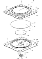
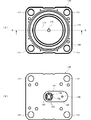
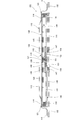
図3は、本発明の実施形態に係るバルブ101の分解斜視図である。図4(A)は、図3のバルブ101に備えられるキャップ部110の上面図である。図4(B)は、図3のバルブ101に備えられるバルブ筐体130の下面図である。図5は、図4(A)のS-S線における断面図である。
バルブ101は、図3~図5に示すように、キャップ部110と、ダイヤフラム120と、受圧板125と、バルブ筐体130と、弁部150とを備える。
バルブ筐体130は、例えば略正方形板状である。バルブ筐体130には、バルブ室140へ流体が流入する流入孔143と、ポンプ103が接続されてポンプ103による流体の吸引圧力によってバルブ室140から流体が流出する流出孔149と、が形成されている。流入孔143は、図5に示すように、当該流入孔143からダイヤフラム120における流入孔143に対向する部分までの距離A(即ち、流入孔143とダイヤフラム120との最短距離)が、流出孔149からダイヤフラム120における流出孔149に対向する部分までの距離B(即ち、流出孔149とダイヤフラム120との最短距離)よりも短くなるように形成されている。
このように形成することにより、バルブ101が開くときに、まず受圧板125がバルブ室140の底面上における流入孔143の周囲と当接する。このため、ダイヤフラム120の撓みによって受圧板125やダイヤフラム120がバルブ筐体130の流出孔149を塞ぐことを抑制できる。
また、バルブ筐体130には、キャップ部110とバルブ筐体130をシステム筐体160に固定するためのネジ止め用の穴131と、キャップ部110の周縁部位114と対向する位置に、液漏れを防ぐシール部134と、が設けられている。
また、バルブ筐体130には、図3及び図5に示すように、弁部150が流入孔143とバルブ室140とを接続させたときに、受圧板125が当接する突出部144と、メタノールを突出部144の内側から外側へ流入させる流路145とが、ダイヤフラム120と対向するバルブ室140の底面141上における流入孔143の周囲に形成されている。
また、バルブ筐体130には、図4(B)及び図5に示すように、弁部150をバルブ筐体130の実装面側から嵌めこむことにより弁部150を収納する開口部147と、流入孔143の周縁に位置する弁座148と、が形成されている。
なお、バルブ筐体130の材質については、バルブ筐体130のメタノールと接する部分141、144、145、148の材質は耐メタノール性の高い樹脂、例えばPPS樹脂等からなり、バルブ筐体130のメタノールと接しない部分である縁部132の材質は金属からなる。バルブ筐体130は、金属部分の縁部132をモールド金型にインサートして射出成形するインサートモールドにより形成される。
ダイヤフラム120は、図3及び図5に示すように、例えば円板状に形成されている。ダイヤフラム120の材質は、耐メタノール性の高い樹脂、例えばPET(Polyethylene Terephthalate)樹脂又はPPS樹脂である。
ダイヤフラム120は、周縁部121がバルブ筐体130上のシール部134に載置されてバルブ筐体130とともにバルブ室140を構成する。シール部134は例えばOリングである。ダイヤフラム120は、バルブ室140の流体の圧力によって周縁部121の内側の中央部122が変位する。ポンプ103による流体(メタノール)の吸引によってバルブ室140の圧力が低下した時、ダイヤフラム120の中央部122が弁部150に近づく方向へ変位して受圧板125を押下し、受圧板125のプッシャー部127が弁部150の弁体部151に当接して弁体部151を押下する。
弁部150は、図3及び図5に示すように、略円形状であり、耐メタノール性の高いゴム、例えばシリコーンゴムからなる。弁部150は、ダイヤフラム120の変位に伴って流入孔143とバルブ室140とを遮断状態から接続状態にして流体(メタノール)の流入を制御する弁体部151と、弁体部151が弁座148に対して接近および離間する方向へ可動自在に弁体部151を支持する支持部152と、メタノールを通過させる孔部153と、弁部150が開口部147に収納されたときにバルブ筐体130の開口部147の内周面に当接し、支持部152を固定する固定部154と、を有する。
なお、弁体部151には、弁座148とのシール性を高めるため、流入孔43側にリング状の弁突起155が形成されているが、弁突起155は必ずしも形成される必要はない。
弁体部151は、弁部150が開口部147に収納されたときに弁体部151の弁突起155が弁座148に当接し、弁体部151が流入孔143からバルブ室140への流体の流入を遮断するよう弁座148を付勢力Fsで付勢する。
弁体部151は、ポンプ103によるメタノールの吸引によってバルブ室140の圧力が低下した時、ダイヤフラム120が下降して受圧板125のプッシャー部127が当接して押し下げられることによって弁座148から離間し、流入孔143とバルブ室140とが接続状態となる。この結果、流入孔143と孔部153が連通して、メタノールがバルブ室140へ流入する。
なお、弁部150が、本発明の「弁体」に相当する。
キャップ部110は、図3、図4(A)及び図5に示すように、略正方形板状であり、例えば、ステンレススチールの板を用いて金型成形により形成される。キャップ部110には、キャップ部110とバルブ筐体130をシステム筐体160に固定するためのネジ止め用の穴111が形成されている。
ここで、金属製のキャップ部110の縁部116は、ダイヤフラム120がシール部134に載置された状態で、バルブ筐体130の金属製の縁部132と溶接により接合される。キャップ部110の周縁部位114は、接合されると、ダイヤフラム120の周縁部121を押圧してシール部134とともに周縁部121を挟持する。ここで、シール部134の材質は、耐メタノール性の高いゴム、例えばエチレンプロピレンゴムまたはシリコーンゴムである。このため、当該シール部134がダイヤフラム120の周縁部121及びバルブ筐体130によって圧縮され、ダイヤフラム120の周縁部121とシール部134との密着性が極めて高くなる。そのため、メタノールがダイヤフラム120の周縁部121とシール部134との間を通過してバルブ室140の外側へ漏れることを防止できる。
また、キャップ部110の中央部位113には、外気と通じる孔部115が形成されている。この結果、ダイヤフラム120の上部に大気圧が加わる。
受圧板125は、例えば円板状に形成され、第1の面と第1の面に対向する第2の面とを備える受圧部126と、受圧部126におけるバルブ筐体130側の第1の面の中心部分から突出し、例えば円柱状に形成されているプッシャー部127とを有する。
受圧板125は、ダイヤフラム120とバルブ筐体130との間に設けられている。受圧部126の第1の面がバルブ筺体130に対向しており、受圧部126の第2の面がダイヤフラム120に対向している。
受圧板125の材質は例えば耐メタノール性の高い樹脂、例えばPPS樹脂等からなる。なお、受圧板125の剛性はダイヤフラム120の剛性より高いことが好ましい。
受圧部126の第2の面の直径は8.5mmである。受圧部126の第2の面は、ダイヤフラム120のバルブ筐体130側の面に非接着状態で当接している。なお、受圧部126とダイヤフラム120は、必ずしも当接する必要はなく、互いに対向していてもよい。
プッシャー部127の受圧部126との接続面の直径は0.5mmである。プッシャー部127の突出方向の先端は、バルブ筐体130の流入孔143を介して弁部150に非接着状態で当接している。
なお、プッシャー部127と弁部150は、必ずしも当接する必要はなく、互いに対向していてもよい。ただし、プッシャー部127の突出方向の先端から弁部150までの距離は、受圧板125の非動作時の状態から、受圧板125が突出部144に当接するまでの距離である動作距離よりも大きい必要がある。
なお、弁部150には、受圧板125のプッシャー部127が載置されるが、弁部150の付勢力Fsは受圧板125の重さに勝る力であるため、受圧板125の重さによって流入孔143とバルブ室140とが接続状態となることはない。
受圧部126の第2の面の面積は、約56.7mm2である。プッシャー部127の底面の面積、即ち、プッシャー部127の受圧部126との接続面の面積は、約0.20mm2である。受圧部126の第2の面の面積は、プッシャー部127の受圧部126との接続面の面積よりも大きく、ダイヤフラム120の中央部122の面積よりも小さく構成されている。ここで、受圧部126の第2の面の面積が大きいほど受圧面積が増えるため、よりダイヤフラム120の撓みを抑制することができる。
なお、受圧板125の受圧部126およびプッシャー部127の形状は、平面視した場合において、円形状であることが好ましい。このように形成すると、プッシャー部127を中心として円周方向に均一に力が加わるため、動作時に傾きが発生しにくい。ただし、これに限るものではなく、受圧部126およびプッシャー部127が楕円形状や多角形状であっても構わない。
ここで、バルブ101の動作について説明する。
図6(A)は、本発明の実施形態に係るバルブ101の弁閉時の模式断面図であり、図6(B)は、本発明の実施形態に係るバルブ101の弁開時の模式断面図である。
バルブ101は、流体の圧力が設定圧力になると、圧力差を利用して弁部150が自動的に開閉するように構成されている。詳述すると、ダイヤフラム120上部の大気の圧力をP0、バルブ上流の1次圧力をP1、バルブ下流の圧力をP2とし、弁体部151の面積(ここでは、弁体部151にリング状の弁突起155が形成されているため弁突起155で囲まれた領域の径で決まる面積)をS1、バルブ室140に接するダイヤフラム120の部分の面積(以下、「受圧面積」と称する。)をS2、弁体部151が弁座148を付勢する力をFsとする。
このとき、圧力の釣り合いから、図6(B)のように弁部150が開く条件は、(P1-P2)S1+Fs<(P0-P2)S2となる。P2がこの条件の圧力より高いと弁部150は閉じ、低いと弁部150は開く。これによって、P2を一定に保つことができる。
そのため、バルブ101では、ポンプ103によるメタノールの吸引によってバルブ室140の圧力が低下した時、ダイヤフラム120の中央部122が変位して受圧板125の受圧部126を押下し、受圧板125のプッシャー部127が変位して弁部150の弁体部151を押下する(図6(B)参照)。これにより、流入孔143とバルブ室140とが接続状態となり、メタノールが流入孔143からバルブ室140へ流入する。
この時、受圧板125は、図5、図6に示すようにダイヤフラム120とバルブ室140の底面141との間に配置されているため、ダイヤフラム120の撓みを抑制することができる。そのため、仮にダイヤフラム120を剛性の低い材料で形成した場合でも、ダイヤフラム120に対向する受圧板125の面(第2の面)の面積分の受圧面積S2は少なくとも確保できる。
したがって、バルブ101では、ダイヤフラム120の受圧面積S2が低下することを抑制できる。そのため、ダイヤフラム120がバルブ室140の底面141に固着することを抑制することができる。
また、流入孔143とバルブ室140とが接続状態となるとき、受圧板125の受圧部126が、バルブ室140の底面でなく突出部144に接触する(図3、図5及び図6(B)参照)。さらに、受圧板125の受圧部126が突出部144に接触した時、メタノールは突出部144の内側から流路145を介して突出部144の外側へ通過する。よって、この実施形態のバルブ101によれば、受圧板125がバルブ筐体130の流入孔143を塞ぐことを防ぐこともできる。
また、バルブ筐体130の流入孔143は、当該流入孔143からダイヤフラム120における流入孔143に対向する部分までの距離A(即ち、流入孔143とダイヤフラム120との最短距離)が、流出孔149からダイヤフラム120における流出孔149に対向する部分までの距離B(即ち、流出孔149とダイヤフラム120との最短距離)よりも短くなるように形成されている。そのため、バルブ101が開くときに、受圧板125はまず、バルブ室140の底面上における流入孔143の周囲に位置する突出部144と当接する。そのため、この実施形態のバルブ101によれば、受圧板125やダイヤフラム120がバルブ筐体130の流出孔149を塞ぐことを抑制できる。
ここで、ダイヤフラム120の変位量について、図7(A)(B)に示すバルブ101と、図8(A)(B)に示すバルブ201とを比較しながら説明する。
図7(A)は、本発明の実施形態に係るバルブ101に備えられるダイヤフラム120及び受圧板125の前記流入孔143と前記バルブ室140とが遮断状態のとき、すなわち弁閉時の断面図である。図7(B)は、本発明の実施形態に係るバルブ101に備えられるダイヤフラム120及び受圧板125の前記流入孔143と前記バルブ室140とが接続状態のとき、すなわち弁開時の断面図である。図8(A)は、本発明の変形例に係るバルブ201に備えられるダイヤフラム120A及び受圧板125Aの弁閉時の断面図である。図8(B)は、本発明の変形例に係るバルブ201に備えられるダイヤフラム120及び受圧板125の弁開時の断面図である。
図8に示すバルブ201が、図7に示すバルブ101と相違する点は、ダイヤフラム120及び受圧板125を接着させた点であり、その他の点については同じである。
ダイヤフラム120及び受圧板125を非接着状態で当接させたバルブ101では、流入孔143とバルブ室140とが接続状態となるとき、図8(B)に示すように、受圧板125がダイヤフラム120の変形を妨げない。受圧板125は、ダイヤフラム120の中央部122の変位に伴って弁体部151側へ変位する。そのため、バルブ101では、受圧板125を配置することによってダイヤフラム120の変位量dが低下しない。
これに対して、ダイヤフラム120A及び受圧板125Aを接着させたバルブ201では、流入孔143とバルブ室140とが接続状態となるとき、図8(B)に示すように、受圧板125がダイヤフラム120の変形を妨げる。このため、バルブ201では、受圧板125を配置することによってダイヤフラム120の変位量dが小さくなる。
従って、この実施形態のバルブ101によれば、ダイヤフラム120の変位量dを低下させずに、ダイヤフラム120の撓みを抑制することができる。
また、ダイヤフラム120がゴムで形成されている場合、ダイヤフラム120の変位は大きいものの、ガス透過性が大きいためガス漏れのおそれがある。このため、ダイヤフラム120の材質は樹脂であることが好ましい。液体を流体としてバルブ101に使用した場合、液体の表面張力が大きいため、気体を流体としてバルブ101に使用した場合より大きな流体の流路が必要となるが、この実施形態のバルブ101ではダイヤフラム120の変位量dが大きいため、ダイヤフラム120の材質が樹脂であってもメタノールの流路を十分に確保できる。
また、この実施形態におけるバルブ101は、受圧板125をダイヤフラム120及び弁体部151に接着する必要がないため、接着工程を使用せずに製造できる。そのため、この実施形態におけるバルブ101によれば、低コストで製造できる。
また、この実施形態におけるバルブ101は、接着工程を使用せずに製造できるため、接着剤の成分がメタノール中に溶出することがない。さらに、バルブ筐体130のメタノールと接する部分141、144、145、148及び受圧板125の材質は全て樹脂であり、ダイヤフラム120と弁部150の材質もゴムであるため、金属イオンがメタノール中に溶出することもない。そのため、この実施形態のバルブ101では、接着剤の成分や金属イオンの溶出によるDMFCの特性の劣化も起こらない。
従って、この実施形態のバルブ101を用いることで、当該バルブ101を備える燃料電池システム100においても同様の効果を奏する。
《その他の実施形態》
前記実施形態では活性の高い流体としてメタノールを用いているが、当該流体が、気体や、液体、気液混合流、固液混合流、固気混合流などのいずれであっても適用できる。
前記実施形態では活性の高い流体としてメタノールを用いているが、当該流体が、気体や、液体、気液混合流、固液混合流、固気混合流などのいずれであっても適用できる。
なお、上述の実施形態の説明は、すべての点で例示であって、制限的なものではないと考えられるべきである。本発明の範囲は、上述の実施形態ではなく、特許請求の範囲によって示される。さらに、本発明の範囲には、特許請求の範囲と均等の意味および範囲内でのすべての変更が含まれることが意図される。
1 ダイヤフラム
2 ピストン
3 弁座部
4 弁体部
5 支持部
8 バルブ室
9 底面
15 孔部
90 バルブ
100 燃料電池システム
101、201 バルブ
102 燃料カートリッジ
103 ポンプ
104 発電セル
110 キャップ部
111 穴
113 中央部位
114 周縁部位
115 孔部
116 縁部
120 ダイヤフラム
121 周縁部
122 中央部
125 受圧板
126 受圧部
127 プッシャー部
130 バルブ筐体
131 穴
132 縁部
134 シール部
140 バルブ室
141 バルブ室底面
143 流入孔
144 突出部
145 流路
147 開口部
148 弁座
149 流出孔
150 弁部
151 弁体部
152 支持部
153 孔部
154 固定部
155 弁突起
160 システム筐体
161、162 Oリング
163 流入路
165 流出路
2 ピストン
3 弁座部
4 弁体部
5 支持部
8 バルブ室
9 底面
15 孔部
90 バルブ
100 燃料電池システム
101、201 バルブ
102 燃料カートリッジ
103 ポンプ
104 発電セル
110 キャップ部
111 穴
113 中央部位
114 周縁部位
115 孔部
116 縁部
120 ダイヤフラム
121 周縁部
122 中央部
125 受圧板
126 受圧部
127 プッシャー部
130 バルブ筐体
131 穴
132 縁部
134 シール部
140 バルブ室
141 バルブ室底面
143 流入孔
144 突出部
145 流路
147 開口部
148 弁座
149 流出孔
150 弁部
151 弁体部
152 支持部
153 孔部
154 固定部
155 弁突起
160 システム筐体
161、162 Oリング
163 流入路
165 流出路
Claims (9)
- 流体の流入孔と、前記流体の流出孔とを有するバルブ筐体と、
周縁部が前記バルブ筐体に固定されて前記バルブ筐体とともにバルブ室を構成し、前記バルブ室の前記流体の圧力によって前記周縁部より内側の中央部が変位するダイヤフラムと、
第1の面と前記第1の面に対向する第2の面とを有する平板状の受圧部と、前記受圧部の前記第1の面に接続された柱状のプッシャー部とを有し、前記受圧部の前記第2の面の面積は、前記プッシャー部の前記受圧部との接続面の面積よりも大きく、前記受圧部の前記第2の面が前記ダイヤフラムの前記バルブ筐体側の面に非接着状態で対向するよう前記バルブ室に配置されている受圧板と、
前記プッシャー部に対向して前記流入孔に配置され、前記ダイヤフラムの変位による前記受圧板の変位に伴って、前記流入孔と前記バルブ室とを遮断状態から接続状態にする弁体と、を備える、バルブ。 - 前記受圧板の剛性は、前記ダイヤフラムの剛性より高い、請求項1に記載のバルブ。
- 前記受圧板は、前記プッシャー部が前記弁体に非接着状態で対向するよう配置されている、請求項1又は2に記載のバルブ。
- 前記バルブ筐体には、前記ダイヤフラムの変位による前記受圧板の変位に伴って前記弁体が前記流入孔と前記バルブ室とを接続状態としたときに、前記受圧板の前記受圧部が対向する突出部と、当該流体を前記突出部の内側から外側へ通過させる流路とが、前記受圧板と対向する前記バルブ室の底面上における前記流入孔の周囲に形成されている、請求項1から3のいずれかに記載のバルブ。
- 前記バルブ筐体の前記流入孔は、前記流入孔から前記ダイヤフラムにおける前記流入孔に対向する部分までの距離が、前記流出孔から前記ダイヤフラムにおける前記流出孔に対向する部分までの距離よりも短くなるように形成されている、請求項1から4のいずれかに記載のバルブ。
- 前記ダイヤフラムの材質は樹脂である、請求項1から5のいずれかに記載のバルブ。
- 前記受圧板の材質は樹脂である、請求項1から6のいずれかに記載のバルブ。
- 前記流体はメタノールである、請求項1から7のいずれかに記載のバルブ。
- 請求項1から8のいずれかに記載のバルブと、
前記バルブの前記流入孔に接続される燃料貯蔵部と、
前記バルブの前記流出孔に接続されるポンプと、を備える燃料電池システム。
Priority Applications (1)
| Application Number | Priority Date | Filing Date | Title |
|---|---|---|---|
| JP2013528044A JP5780304B2 (ja) | 2011-08-10 | 2012-08-08 | バルブ、燃料電池システム |
Applications Claiming Priority (2)
| Application Number | Priority Date | Filing Date | Title |
|---|---|---|---|
| JP2011-174687 | 2011-08-10 | ||
| JP2011174687 | 2011-08-10 |
Publications (1)
| Publication Number | Publication Date |
|---|---|
| WO2013022018A1 true WO2013022018A1 (ja) | 2013-02-14 |
Family
ID=47668524
Family Applications (1)
| Application Number | Title | Priority Date | Filing Date |
|---|---|---|---|
| PCT/JP2012/070168 Ceased WO2013022018A1 (ja) | 2011-08-10 | 2012-08-08 | バルブ、燃料電池システム |
Country Status (2)
| Country | Link |
|---|---|
| JP (1) | JP5780304B2 (ja) |
| WO (1) | WO2013022018A1 (ja) |
Citations (3)
| Publication number | Priority date | Publication date | Assignee | Title |
|---|---|---|---|---|
| JPH1139042A (ja) * | 1997-07-20 | 1999-02-12 | Hamai:Kk | 圧力調整器 |
| JP2002364947A (ja) * | 2001-06-07 | 2002-12-18 | Techno Excel Co Ltd | 空気調和装置の空冷凝縮器の噴霧冷却装置用の減圧給水装置 |
| JP2005339321A (ja) * | 2004-05-28 | 2005-12-08 | Tokai Corp | 圧力調整器 |
Family Cites Families (6)
| Publication number | Priority date | Publication date | Assignee | Title |
|---|---|---|---|---|
| JPS57186770U (ja) * | 1981-05-21 | 1982-11-26 | ||
| JPS5874679U (ja) * | 1981-11-12 | 1983-05-20 | 株式会社ノーリツ | ガスガバナ等のダイヤフラム装置 |
| JPH0410448Y2 (ja) * | 1985-04-11 | 1992-03-16 | ||
| JP2005309983A (ja) * | 2004-04-23 | 2005-11-04 | Aisin Seiki Co Ltd | ガス制御弁および燃料電池システム |
| JP2006046196A (ja) * | 2004-08-05 | 2006-02-16 | Aisan Ind Co Ltd | 流体用レギュレータ |
| JP4922775B2 (ja) * | 2007-01-29 | 2012-04-25 | 株式会社フジキン | 流体制御器 |
-
2012
- 2012-08-08 WO PCT/JP2012/070168 patent/WO2013022018A1/ja not_active Ceased
- 2012-08-08 JP JP2013528044A patent/JP5780304B2/ja active Active
Patent Citations (3)
| Publication number | Priority date | Publication date | Assignee | Title |
|---|---|---|---|---|
| JPH1139042A (ja) * | 1997-07-20 | 1999-02-12 | Hamai:Kk | 圧力調整器 |
| JP2002364947A (ja) * | 2001-06-07 | 2002-12-18 | Techno Excel Co Ltd | 空気調和装置の空冷凝縮器の噴霧冷却装置用の減圧給水装置 |
| JP2005339321A (ja) * | 2004-05-28 | 2005-12-08 | Tokai Corp | 圧力調整器 |
Also Published As
| Publication number | Publication date |
|---|---|
| JPWO2013022018A1 (ja) | 2015-03-05 |
| JP5780304B2 (ja) | 2015-09-16 |
Similar Documents
| Publication | Publication Date | Title |
|---|---|---|
| US9574674B2 (en) | Valve, fluidic apparatus, and fluid-supplying apparatus | |
| JP5062327B2 (ja) | マイクロバルブ及びバルブシート部材 | |
| JP6000940B2 (ja) | 圧力安定化器組立体 | |
| JP5582250B2 (ja) | 順止バルブ、燃料電池システム | |
| CA3093238A1 (en) | Pressure loaded regulator with dual diaphragm and redundant seal | |
| JP5780304B2 (ja) | バルブ、燃料電池システム | |
| US10711906B2 (en) | Valve and fuel cell system | |
| JP5565464B2 (ja) | 順止バルブ、燃料電池システム | |
| CN101405527A (zh) | 一体化双膜隔膜阀 | |
| JP5510551B2 (ja) | 順止バルブ、燃料電池システム | |
| JP2020041643A (ja) | リリーフ弁 | |
| JP5527101B2 (ja) | 順止バルブ、燃料電池システム | |
| JP5817314B2 (ja) | 順止バルブ、燃料電池システム | |
| JP2012021623A (ja) | 高圧遮断バルブ、燃料カートリッジ、及び燃料電池システム | |
| JP5664014B2 (ja) | 順止バルブ、燃料電池システム | |
| JP6157237B2 (ja) | パイロット式開閉弁およびこれを備えた逆流防止装置 | |
| JP2008151243A (ja) | リリーフバルブ | |
| JP7740501B2 (ja) | バルブ、および、流体制御装置 | |
| JP5510548B2 (ja) | 順止バルブ、燃料電池システム |
Legal Events
| Date | Code | Title | Description |
|---|---|---|---|
| 121 | Ep: the epo has been informed by wipo that ep was designated in this application |
Ref document number: 12822537 Country of ref document: EP Kind code of ref document: A1 |
|
| ENP | Entry into the national phase |
Ref document number: 2013528044 Country of ref document: JP Kind code of ref document: A |
|
| NENP | Non-entry into the national phase |
Ref country code: DE |
|
| 122 | Ep: pct application non-entry in european phase |
Ref document number: 12822537 Country of ref document: EP Kind code of ref document: A1 |