WO2013022013A1 - 多方向移動体モジュール - Google Patents
多方向移動体モジュール Download PDFInfo
- Publication number
- WO2013022013A1 WO2013022013A1 PCT/JP2012/070149 JP2012070149W WO2013022013A1 WO 2013022013 A1 WO2013022013 A1 WO 2013022013A1 JP 2012070149 W JP2012070149 W JP 2012070149W WO 2013022013 A1 WO2013022013 A1 WO 2013022013A1
- Authority
- WO
- WIPO (PCT)
- Prior art keywords
- belt
- moving
- driving
- pair
- bodies
- Prior art date
- Legal status (The legal status is an assumption and is not a legal conclusion. Google has not performed a legal analysis and makes no representation as to the accuracy of the status listed.)
- Ceased
Links
Images





Classifications
-
- B—PERFORMING OPERATIONS; TRANSPORTING
- B62—LAND VEHICLES FOR TRAVELLING OTHERWISE THAN ON RAILS
- B62D—MOTOR VEHICLES; TRAILERS
- B62D55/00—Endless track vehicles
- B62D55/08—Endless track units; Parts thereof
- B62D55/18—Tracks
- B62D55/26—Ground engaging parts or elements
-
- B—PERFORMING OPERATIONS; TRANSPORTING
- B62—LAND VEHICLES FOR TRAVELLING OTHERWISE THAN ON RAILS
- B62D—MOTOR VEHICLES; TRAILERS
- B62D15/00—Steering not otherwise provided for
-
- B—PERFORMING OPERATIONS; TRANSPORTING
- B62—LAND VEHICLES FOR TRAVELLING OTHERWISE THAN ON RAILS
- B62D—MOTOR VEHICLES; TRAILERS
- B62D55/00—Endless track vehicles
- B62D55/08—Endless track units; Parts thereof
- B62D55/18—Tracks
- B62D55/20—Tracks of articulated type, e.g. chains
-
- B—PERFORMING OPERATIONS; TRANSPORTING
- B60—VEHICLES IN GENERAL
- B60B—VEHICLE WHEELS; CASTORS; AXLES FOR WHEELS OR CASTORS; INCREASING WHEEL ADHESION
- B60B19/00—Wheels not otherwise provided for or having characteristics specified in one of the subgroups of this group
- B60B19/003—Multidirectional wheels
-
- B—PERFORMING OPERATIONS; TRANSPORTING
- B60—VEHICLES IN GENERAL
- B60B—VEHICLE WHEELS; CASTORS; AXLES FOR WHEELS OR CASTORS; INCREASING WHEEL ADHESION
- B60B19/00—Wheels not otherwise provided for or having characteristics specified in one of the subgroups of this group
- B60B19/12—Roller-type wheels
Definitions
- the present invention relates to a multidirectional moving body module applied to a moving means for a passenger and a conveying means for conveying an object to be conveyed.
- a method of rotating a moving body for example, there is a method of changing a moving direction by tilting a rotating body such as a tire provided in a vehicle. Also, a method of moving a moving body by an endless track provided on a pair of left and right moving bodies such as a vehicle or a so-called mecanum wheel that changes a moving direction by a roller body provided on a wheel body (see, for example, Patent Document 1) .)
- the load concentrates on one axis of one roller body, so that the allowable load is limited, and only one of the plurality of roller bodies is moved in a state where it is always in contact with the traveling surface, that is, the moving surface. Since the driving force of the body body is obtained, there is a problem that it is difficult to move smoothly and freely in a state where the contact area is increased and the load is dispersed. Further, when the above-described wheels are arranged at the four corners of a moving body main body such as a vehicle in order to reduce the load, the roller shaft diameter that supports the roller body provided on each wheel is increased to increase the strength of the drive shaft. Therefore, there is a problem that the size of the moving body, that is, the moving mechanism increases.
- the technical problem to be solved by the present invention is to prevent wear on the moving surface, increase in the size of the mechanism along the height direction, damage to the moving surface and endless shape, and the moving surface. It is to provide a multi-directional moving body module that moves smoothly and freely in a multi-directional manner.
- a multidirectional moving body module includes a moving body module main body that moves along a moving surface, and is provided in the moving body module main body and is driven independently of each other.
- a pair of belt-like drive bodies and rotation axes that are arranged in the belt-like drive body along the drive direction of the belt-like drive body and are oblique to the drive direction of the belt-like drive body are parallel to each other.
- the multidirectional moving body module which concerns on invention of Claim 2 is a multidirectional moving body module which concerns on invention of Claim 1,
- belt-shaped drive body is mutually parallel.
- the multidirectional moving body module according to the invention of claim 3 is the multidirectional moving body module according to the invention of claim 2, wherein the rotation axis of the rotating body provided on one of the pair of belt-like driving bodies and the The rotation axis of the rotating body provided on the other of the pair of belt-like driving bodies intersects with each other, thereby further solving the above-described problem.
- the multidirectional moving body module which concerns on invention of this invention 4 is a multidirectional moving body module which concerns on invention of Claim 3, and the rotating shaft of the rotary body provided in one side of said pair of strip
- the multi-directional moving body module according to the invention of claim 5 is the multi-directional moving body module according to any one of claims 1 to 4, wherein the pair of belt-like driving bodies are the moving body.
- the above-described problems are further solved by having endless shapes that are driven to move forward and backward while being wound around a power transmission rotating body provided in the module body.
- a multi-directional moving body module is provided with a moving body module main body that moves along a moving surface, and is provided on the moving body module main body and is driven independently of each other.
- a pair of belt-like drive bodies and a rotation shaft that is arranged in the belt-like drive body along the drive direction of the belt-like drive body and that is oblique to the drive direction of the belt-like drive body are respectively attached in parallel.
- a plurality of rotating bodies each contacting the outer peripheral surface with the moving surface in a state where the outer peripheral surface of each of the plurality of rotating bodies is in contact with the moving surface.
- the driving force of the moving body module body is generated in the direction of the reaction force acting on each rotating body from the moving surface according to the acting force based on the load of the moving body module body.
- the size of the multi-directional moving body module is increased, that is, the size and the moving surface are changed by changing the design of the outer peripheral surface of each rotating body and the center of gravity of the moving body module to a high position.
- belt-shaped drive body mutually mutually Because of the parallelism, the driving direction and the driving speed of each of the pair of belt-like driving bodies are controlled to adjust the moving speed and the direction of the moving body module body. Can be moved smoothly and freely in multiple directions along the moving surface.
- the multi-directional moving body module according to the third aspect of the invention has the effect of the multi-directional moving body module according to the second aspect of the invention in addition to the rotating body provided on one of the pair of belt-like driving bodies.
- the rotation axes are disordered obliquely in the driving direction of the belt-like driving body. Therefore, it is easy to set the magnitude and direction of the reaction force acting on each rotating body from the moving surface, so that the mobile module main body is moved along the moving surface by a drive control system and method using a simple control process. It can be moved smoothly and freely in multiple directions.
- belt-shaped drive body in addition to the effect which the multidirectional moving body module which concerns on invention of Claim 3 show
- the rotating shaft and the rotating shaft of the rotating body provided on the other of the pair of belt-shaped driving bodies form an angle of 45 ° with respect to the driving direction of the belt-shaped driving body, so that each rotating shaft is driven randomly.
- the multi-directional moving body module according to the invention of claim 5 has a pair of belt-like driving bodies in addition to the effect exhibited by the multi-directional moving body module according to any one of claims 1 to 4.
- Each of the rotating bodies is grounded to the moving surface, that is, the ground plane, by having an endless shape that is driven to move forward and backward while being wound around a rotating body for power transmission provided in the moving body module body. In this state, the entire load acting on the rotating body from the moving surface is shared and supported by each rotating body to reduce the load load between the rotating body and its rotating shaft, so the load load between the rotating body and its rotating shaft is reduced.
- the conceptual diagram which showed the some rotary body in FIG. The conceptual diagram which showed the moving direction which a multi-directional moving body module moves when a pair of strip
- the multidirectional moving body module of the present invention includes a moving body module main body that moves along a moving surface, and a pair of belt-like driving bodies that are provided on the moving body module main body and are driven independently of each other. And a moving surface in a state in which the rotation shafts arranged in the belt-like drive body along the drive direction of the belt-like drive body and obliquely intersecting with the drive direction of the belt-like drive body are mounted so as to be parallel to each other.
- a plurality of rotating bodies that contact the outer peripheral surface respectively, and prevent wear on the moving surface, increase in the size of the mechanism along the height direction, and damage to the traveling surface, that is, the moving surface and the endless track, along the moving surface.
- the belt-like drive body may be a belt made of resin or metal, or may be a chain.
- the plurality of rotating bodies is a state in which at least two rotating bodies adjacent to each other along the driving direction of the belt-like driving body among the plurality of rotating bodies are arranged as a set at regular intervals. May be arranged.
- the rotating bodies arranged in each of the pair of band-shaped driving bodies may be arranged alternately along the driving direction of the band-shaped driving bodies to constitute a staggered arrangement as a whole.
- a plurality of a pair of belt-like driving bodies each having a plurality of rotating bodies arranged therein may be provided in the driving direction of the belt-like driving body, or may be provided in a plurality in the width direction of the belt-like driving body.
- FIG. 1 is a perspective view of a multidirectional mobile module according to an embodiment of the present invention
- FIG. 2 is a conceptual diagram of the multidirectional mobile module according to an embodiment of the present invention
- FIG. 2 is a conceptual diagram showing a plurality of rotating bodies in FIG. 2
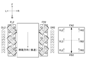
- FIG. 4 is a conceptual diagram showing a moving direction in which a multidirectional moving body module moves when a pair of belt-like driving bodies are driven in the forward direction at the same speed.
- FIG. 1 is a perspective view of a multidirectional mobile module according to an embodiment of the present invention
- FIG. 2 is a conceptual diagram showing a plurality of rotating bodies in FIG. 2
- FIG. 4 is a conceptual diagram showing a moving direction in which a multidirectional moving body module moves when a pair of belt-like driving bodies are driven in the forward direction at the same speed.
- FIG. 5 is a conceptual diagram showing a moving direction in which a multi-directional moving body module moves when a pair of belt-like driving bodies are driven in the opposite direction at the same speed
- FIG. 6 is a pair of belt-like driving bodies.
- FIG. 7 is a conceptual diagram showing a moving direction in which the multidirectional moving body module moves when the body is driven in the forward direction and the reverse direction at the same speed.
- FIG. 7 shows a pair of belt-like drive bodies in the reverse direction and the forward direction.
- It is a conceptual diagram showing the moving direction in which the multidirectional moving body module moves when driven at speed
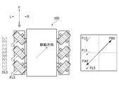
- FIG. 8 is a conceptual diagram showing a moving direction in which the multidirectional moving body module moves when only one of the pair of belt-like driving bodies is driven
- FIG. 9 shows the pair of belt-like driving bodies in the forward direction and FIG. 10 is a conceptual diagram showing a moving direction in which the multi-directional moving body module moves when driven in opposite directions at different speeds, and FIG. 10 drives a pair of belt-like driving bodies at different speeds in the forward direction. It is the conceptual diagram which showed the moving direction to which a multidirectional moving body module moves at the time.
- driving the belt-like drive body in the forward direction means driving the grounding surface side portion of the belt-like drive body, that is, the lower portion, which is the moving surface side portion, in the backward direction B and the upper portion of the belt-like drive body. Is driven in the forward direction F.
- driving the belt-like drive body in the reverse direction means driving the entire belt-like drive body in the opposite direction to the above-described forward direction.
- the multidirectional moving body module 100 includes a moving body module main body 110 that moves along the moving surface P, and the moving body module main body 110 that is provided on the moving body module main body 110 and that advances and retreats independently of each other.
- a plurality of rotating bodies 130 are provided to bring the outer peripheral surface 130S into contact with the moving surface P in a state in which the shafts 131 are mounted so as to be parallel to each other.
- the load of the movable body module main body 110 is shared and supported by each rotary body 130 in a state where the outer peripheral surfaces 130 ⁇ / b> S of the plurality of rotary bodies 130 are in contact with the moving plane P.
- the driving force of the moving body module main body 110 is generated in the direction of the reaction force acting on each rotating body 130 from the moving surface P according to the acting force based on the load of the moving body module main body 110.
- the sliding of the rotating body 130 with respect to the moving surface P is suppressed.
- a chain is used as the belt-like drive body 120.
- the drive shaft 141LF and the drive shaft 141RF are not connected to each other.
- the drive shaft 141LB and the drive shaft 141RB are also not connected to each other.
- the drive motor 142F moves the power transmission rotor 140LF out of a pair of power transmission rotors 140LF and 140LB arranged in parallel in the vertical direction in the drawing, that is, in the forward direction F and the backward direction B of the multidirectional mobile module 100.
- the power transmission rotator 140LB is driven with respect to the power transmission rotator 140LF.
- the drive motor 142B moves the power transmission rotor 140RB out of the pair of power transmission rotors 140RF and 140RB arranged in parallel in the vertical direction in the drawing, that is, in the forward direction F and the backward direction B of the multi-directional moving body module 100.
- the power transmission rotator 140RF is driven with respect to the power transmission rotator 140RB. That is, the belt-like driving bodies 120 and 120 arranged on the left and right in the drawing are driven independently of each other.
- FIG. 142B is arranged.
- the driving directions of the pair of belt-like driving bodies 120 and 120 are parallel to each other.
- the multidirectional moving body module 100 can adjust the moving speed and direction of the moving body module main body 110 by controlling the driving direction and driving speed of each of the pair of belt-like driving bodies 120 and 120.
- the mobile module main body 110 moves smoothly and freely in multiple directions along the moving surface P with a simple drive control system and method.
- the axes 131A intersect each other.
- the multidirectional moving body module 100 has a larger resultant force of the reaction force acting on each rotating body 130 from the moving surface P than when the rotating shafts 131A are obliquely crossed in the driving direction of the belt-like driving body 120. It becomes easy to set the height and its direction. For this reason, the moving body module main body 110 moves smoothly and freely in multiple directions along the moving surface P by a drive control system and method using a simple control process.
- the rotation shaft 131 of the rotating body 130 provided on one of the pair of belt-like driving bodies 120 and 120 and the rotation shaft 131 of the rotating body 130 provided on the other of the pair of belt-like driving bodies 120 and 120 are belt-like driving.
- An angle of 45 ° is formed with respect to the driving direction of the body 120.
- the multidirectional moving body module 100 can move efficiently and reliably along all directions.
- the pair of belt-like drive bodies 120 and 120 each have an endless shape, that is, an endless track, which is driven to move forward and backward while being wound around the power transmission rotating bodies 140F and 140R provided in the movable body module main body 110. is doing.
- the multidirectional moving body module 100 causes each rotating body 130 to share and support the entire load acting on the rotating body 130 from the moving surface P in a state where the plurality of rotating bodies 130 are grounded to the moving surface P, that is, the ground surface.
- the load burden between the rotating body 130 and the rotating shaft 131 is reduced.
- the multi-directional moving body module 100 includes the rotating body 130 and the supporting portion of the rotating body 130 that accompany the increase of the shaft diameter of the rotating shaft 131 in order to reduce the load load between each rotating body 130 and the rotating shaft 131. It is designed to prevent an increase in size.
- the mobile module main body 110 moves smoothly and freely in multiple directions along the moving surface P without increasing the center of gravity of the multidirectional mobile module 100.
- the drive motor 142B drives the power transmission rotating body 140RB.
- the power transmission rotator 140RF is installed in parallel with the power transmission rotator 140RB along the vertical direction in the drawing, that is, the front-rear direction.
- the power transmission rotator 140RF follows the drive of the power transmission rotator 140RB by the drive motor 142B.
- the power transmission rotator 140LB is disposed in parallel with the power transmission rotator 140LF along the vertical direction in the drawing, that is, the front-rear direction.
- the power transmission rotating body 140LB follows the driving of the power transmission rotating body 140LF by the drive motor 142F.
- the forward direction F, the backward direction B, the right traveling direction R, and the left traveling direction L of the multidirectional moving body module 100 are indicated by arrows in FIGS.
- the V-shaped and inverted V-shaped white arrows shown in FIG. 1 and FIGS. 4 to 10 indicate the velocity vector of the lower part facing the moving surface P of the belt-like driving body 120 having an endless shape, that is, an endless track.
- the speed vector D of the lower part facing the moving surface P in the belt-like drive body 120 shown in FIG. 1 is the speed vector DR1, DL1 of the belt-like drive body 120 shown in FIG. It matches.
- Such a speed vector is set in consideration of the driving speed and direction of the belt-like driving body 120, the arrangement direction of the rotating body 130, various parameters of the configuration and position, and the driving force of the driving motors 142F and 142B. .
- the moving direction of the multidirectional moving body module 100 shown below is an example, and the multidirectional moving body module 100 changes the combination of the magnitudes and orientations of the velocity vectors of the pair of belt-like driving bodies 120 and 120. It is possible to move in all directions within the moving surface P.
- each rotating body 130 is used.
- the direction of the resultant force vector FA1 which is the sum of the acting force vectors FR1 and FL1 acting on the moving surface P from the outer peripheral surface 130S, coincides with the backward direction B.
- the direction of the reaction force FB1 acting on the multidirectional moving body module 100 from the moving surface P in accordance with the resultant force vector FA1 coincides with the forward direction F.
- the multidirectional moving body module 100 moves in the forward direction F.
- the speed vectors DR3 and DL3 of the pair of belt-like driving bodies 120 and 120 have the same magnitude, the direction of the speed vector DR3 coincides with the backward direction B, and the speed.
- the direction of the resultant force vector FA3 which is the sum of the acting force vectors FR3 and FL3 acting on the moving surface P from the outer circumferential surface 130S of each rotating body 130, is the rightward traveling direction R.
- the direction of the reaction force FB3 that acts on the multidirectional moving body module 100 from the moving surface P corresponds to the clockwise direction according to the resultant force vector FA3.
- the multidirectional moving body module 100 is rotationally driven in the clockwise direction.
- the speed vectors DR4 and DL4 of the pair of belt-like driving bodies 120 and 120 have the same magnitude, the direction of the speed vector DR4 coincides with the forward direction F, and the speed.
- the direction of the resultant force vector FA4 which is the sum of the acting force vectors FR4 and FL4 acting on the moving surface P from the outer circumferential surface 130S of each rotating body 130 is the left traveling direction L.
- the direction of the reaction force FB4 acting on the multidirectional moving body module 100 from the moving surface P corresponds to the counterclockwise direction according to the resultant force vector FA4.
- the multidirectional moving body module 100 is rotationally driven in the counterclockwise direction.
- the speed vector DL5 of the other drive chain 120 is used.
- the acting force vector FL5 acts on the moving surface P from the outer peripheral surface 130S of each rotating body 130 provided in the other drive chain 120. .
- the rotating body 130 provided on one drive chain 120 releases the load of the moving body module main body 110.
- the substantial magnitude of the resultant force vector FA5 becomes larger than the magnitude of the acting force vector FL5, and the direction thereof coincides with the direction forming 45 ° with respect to each of the left traveling direction L and the backward direction B.
- the direction of the reaction force FB5 acting on the multidirectional moving body module 100 from the moving surface P in accordance with the resultant force vector FA5 coincides with the direction forming 45 ° with respect to each of the right traveling direction R and the forward direction F.
- the multidirectional moving body module 100 moves in a direction that forms 45 ° with respect to the direction of the reaction force FB5, that is, the rightward traveling direction R and the forward traveling direction F.
- the magnitude of the velocity vector DR6 of the pair of belt-like drive bodies 120, 120 is not zero and smaller than the magnitude of the velocity vector DL6, and the direction of the velocity vector DR6 is the forward direction F.
- the direction of the velocity vector DL6 matches the backward direction B
- the acting force vectors FR6 and FL6 act on the moving surface P from the outer peripheral surface 130S of each rotating body 130.
- a reaction force FB6 is generated in a direction in which the clockwise direction is obliquely deflected according to the resultant force vector FA6 which is the sum of the acting force vectors FR6 and FL6.
- the multidirectional moving body module 100 is rotated according to the reaction force FB6 generated in the deflected direction.
- the speed vector DR7 of the pair of belt-like driving bodies 120 and 120 is not zero and smaller than the speed vector DL7, and the direction of the speed vector DR7 is the backward direction B.
- the direction of the velocity vector DL7 coincides with the backward direction B
- the acting force vectors FR7 and FL7 act on the moving surface P from the outer circumferential surface 130S of each rotating body 130.
- a reaction force FB7 is generated in a direction in which the clockwise direction is obliquely deflected according to the resultant force vector FA7 which is the sum of the acting force vectors FR7 and FL7.
- the multidirectional moving body module 100 is rotated according to the reaction force FB7 generated in the deflected direction.
- the multi-directional moving body module 100 of the present embodiment obtained in this way includes the moving body module main body 110, a pair of belt-like driving bodies 120, 120, and a plurality of rotating bodies 130.
- the size of the multi-directional mobile module 100 is increased by changing the design of the outer peripheral surface 130S at 130 and the center of gravity of the mobile module main body 110 to a high position, that is, increasing the size and damaging the outer peripheral surface 130S of the moving surface P and the rotating body 130.
- the movable body module body 110 can be moved smoothly and freely in multiple directions along the moving surface P.
- Multi-directional moving body module 110 ... Moving body module main body 120 ... Band-shaped drive body 130 ... Rotating body 130S ... Outer peripheral surface of rotating body 131 ... Rotating shaft 131A ... Rotation Axis 140LF, 140LB, 140RF, 140RB ... Power transmission rotor 141LF, 141LB, 141RF, 141RB ... Drive shaft 142F, 142B ... Drive motor D ... Speed vector DR1, DR2 , DR3, DR4, DR6, DR7 ... Speed vector of the belt-like drive part provided on the right side DL1, DL2, DL3, DL4, DL5, DL6, DL7 ...
Landscapes
- Engineering & Computer Science (AREA)
- Chemical & Material Sciences (AREA)
- Combustion & Propulsion (AREA)
- Transportation (AREA)
- Mechanical Engineering (AREA)
- Toys (AREA)
Abstract
移動面に対する摩耗と高さ方向に沿った機構のサイズ増大と走行面すなわち移動面や無限軌道の損傷とを防ぐとともに移動面に沿って多方向に円滑且つ自在に安定して移動する多方向移動体モジュールを提供すること。 移動体モジュール本体(110)と、一対の帯状駆動体(120、120)と、帯状駆動体(120)の駆動方向に対して斜交する回転軸(131)に軸着された状態で移動面(P)に外周面(130S)をそれぞれ接触させる複数の回転体(130)とを備えている多方向移動体モジュール(100)。
Description
本発明は、搭乗者の移動手段や被搬送物を搬送する搬送手段に応用される多方向移動体モジュールに関するものである。
従来、移動体を転回する方法としては、例えば車両に設けられたタイヤなどの回転体を傾けて移動方向を変更する方法がある。
また、車両などの移動体に左右一対で設けられた無限軌道によって移動体を移動させる方法やホイール体に設けられたローラ体によって移動方向を変更するホイールいわゆるメカナムホイール(例えば、特許文献1参照。)もある。
また、車両などの移動体に左右一対で設けられた無限軌道によって移動体を移動させる方法やホイール体に設けられたローラ体によって移動方向を変更するホイールいわゆるメカナムホイール(例えば、特許文献1参照。)もある。
しかしながら、上述したホイールでは、一つのローラ体の一軸に荷重が集中してしまうため許容荷重に制限があるうえ複数のローラ体の一つのみを走行面すなわち移動面に常時接触させた状態で移動体本体の駆動力を得ているため、接触面積を増大させて荷重を分散した状態で円滑且つ自在な移動が困難であるという問題点があった。
また、負荷を軽減させるために上述のホイールを車両などの移動体本体の四隅に配置した場合、各ホイールに設けられたローラ体を軸支するローラ軸径を大きくして駆動軸の強度を高めるため、移動体すなわち移動機構のサイズが増大するという問題点があった。
加えて、駆動軸の強度を高めた状態で移動体本体の荷重を支えるため、ホイール体のサイズ増大に伴って接地面すなわち移動面に対する移動体の重心を高く設定する設計変更を生じさせて移動体の移動が不安定になるという問題点があった。
そして、移動体の駆動機構として無限軌道等の無端形状を採用した場合、移動体の転回時に無端形状と移動面との間に「滑り」が生じるため、無端形状が摩耗してしまうとともに移動面及び無端形状が損傷するおそれがあるという問題点があった。
また、負荷を軽減させるために上述のホイールを車両などの移動体本体の四隅に配置した場合、各ホイールに設けられたローラ体を軸支するローラ軸径を大きくして駆動軸の強度を高めるため、移動体すなわち移動機構のサイズが増大するという問題点があった。
加えて、駆動軸の強度を高めた状態で移動体本体の荷重を支えるため、ホイール体のサイズ増大に伴って接地面すなわち移動面に対する移動体の重心を高く設定する設計変更を生じさせて移動体の移動が不安定になるという問題点があった。
そして、移動体の駆動機構として無限軌道等の無端形状を採用した場合、移動体の転回時に無端形状と移動面との間に「滑り」が生じるため、無端形状が摩耗してしまうとともに移動面及び無端形状が損傷するおそれがあるという問題点があった。
そこで、本発明が解決しようとする技術的課題、すなわち、本発明の目的は、移動面に対する摩耗と高さ方向に沿った機構のサイズ増大と移動面や無端形状の損傷とを防ぐとともに移動面に沿って多方向に円滑且つ自在に安定して移動する多方向移動体モジュールを提供することである。
まず、本請求項1の発明に係る多方向移動体モジュールは、移動面に沿って移動する移動体モジュール本体と、前記移動体モジュール本体に設けられているとともに相互に独立して進退自在に駆動される一対の帯状駆動体と、前記帯状駆動体の駆動方向に沿って前記帯状駆動体に配列されているとともに前記帯状駆動体の駆動方向に対して斜交する回転軸がそれぞれ平行となるように軸着された状態で前記移動面に外周面をそれぞれ接触させる複数の回転体とを備えていることにより、前述した課題を解決したものである。
そして、本請求項2の発明に係る多方向移動体モジュールは、請求項1の発明に係る多方向移動体モジュールにおいて、前記一対の帯状駆動体のそれぞれの駆動方向が、相互に平行であることにより、前述した課題をさらに解決したものである。
そして、本請求項3の発明に係る多方向移動体モジュールは、請求項2の発明に係る多方向移動体モジュールにおいて、前記一対の帯状駆動体の一方に設けられた回転体の回転軸線と前記一対の帯状駆動体の他方に設けられた回転体の回転軸線とが、相互に交差していることにより、前述した課題をさらに解決したものである。
そして、本請求項4の発明に係る多方向移動体モジュールは、請求項3の発明に係る多方向移動体モジュールにおいて、前記一対の帯状駆動体の一方に設けられた回転体の回転軸と前記一対の帯状駆動体の他方に設けられた回転体の回転軸とが、前記帯状駆動体の駆動方向に対して45°の角度を形成していることにより、前述した課題をさらに解決したものである。
そして、本請求項5の発明に係る多方向移動体モジュールは、請求項1乃至請求項4のいずれか一つの発明に係る多方向移動体モジュールにおいて、前記一対の帯状駆動体が、前記移動体モジュール本体に設けられた動力伝達用回転体に巻き掛けられた状態で進退自在に駆動される無端形状をそれぞれ有していることにより、前述した課題をさらに解決したものである。
本発明の請求項1の発明に係る多方向移動体モジュールは、移動面に沿って移動する移動体モジュール本体と、移動体モジュール本体に設けられているとともに相互に独立して進退自在に駆動される一対の帯状駆動体と、帯状駆動体の駆動方向に沿って帯状駆動体に配列されているとともに帯状駆動体の駆動方向に対して斜交する回転軸がそれぞれ平行となるように軸着された状態で移動面に外周面をそれぞれ接触させる複数の回転体とを備えていることにより、複数の回転体のそれぞれの外周面を移動面に接触させた状態で移動体モジュール本体の荷重を各回転体で分担支持するとともに移動体モジュール本体の荷重に基づく作用力に応じて移動面から各回転体に作用する反作用力の向きに移動体モジュール本体の駆動力を発生させ、しかも移動面に対する回転体の滑りを抑えるため、各回転体における外周面の摩耗と移動体モジュール本体の重心を高い位置に設計変更することによる多方向移動体モジュールの大型化すなわちサイズ増大と移動面や回転体における外周面の損傷とを防ぐとともに移動面に沿って多方向に円滑且つ自在に移動体モジュール本体を移動させることができる。
そして、本請求項2の発明に係る多方向移動体モジュールは、請求項1の発明に係る多方向移動体モジュールが奏する効果に加えて、一対の帯状駆動体のそれぞれの駆動方向が、相互に平行であることにより、一対の帯状駆動体のそれぞれの駆動方向及び駆動速度を制御して移動体モジュール本体の移動速度及びその方向を調整するため、簡便な駆動制御システム及び方法で移動体モジュール本体を移動面に沿って多方向に円滑且つ自在に移動させることができる。
そして、本請求項3の発明に係る多方向移動体モジュールは、請求項2の発明に係る多方向移動体モジュールが奏する効果に加えて、一対の帯状駆動体の一方に設けられた回転体の回転軸線と一対の帯状駆動体の他方に設けられた回転体の回転軸線とが、相互に交差していることにより、各回転軸を無秩序に帯状駆動体の駆動方向に斜交させる場合に比べて移動面から各回転体に作用する反作用力の合力の大きさ及びその方向を設定し易くなるため、簡便な制御プロセスを用いた駆動制御システム及び方法で移動体モジュール本体を移動面に沿って多方向に円滑且つ自在に移動させることができる。
そして、本請求項4の発明に係る多方向移動体モジュールは、請求項3の発明に係る多方向移動体モジュールが奏する効果に加えて、一対の帯状駆動体の一方に設けられた回転体の回転軸と一対の帯状駆動体の他方に設けられた回転体の回転軸とが、帯状駆動体の駆動方向に対して45°の角度を形成していることにより、各回転軸を無秩序に駆動方向に斜交させている場合に比べて移動面から各回転体に作用する反作用力の合力方向をより一層設定しやくすなるため、簡便な制御プロセスを用いた駆動制御システム及び方法で移動体モジュール本体を移動面に沿って多方向に円滑且つ自在に移動させることを確実に実現できる。
そして、本請求項5の発明に係る多方向移動体モジュールは、請求項1乃至請求項4のいずれか一つの発明に係る多方向移動体モジュールが奏する効果に加えて、一対の帯状駆動体が、移動体モジュール本体に設けられた動力伝達用回転体に巻き掛けられた状態で進退自在に駆動される無端形状をそれぞれ有していることにより、複数の回転体を移動面すなわち接地面に接地させた状態で移動面から回転体に作用する荷重全体を各回転体に分担支持させて回転体及びその回転軸間の荷重負担を軽減するため、回転体及びその回転軸間の荷重負担を下げるために回転軸の軸径を大きくすることで生じ得る回転体や回転体の支持部のサイズ増大を防ぎ、多方向移動体モジュールの重心を高くすることなく移動体モジュール本体を移動面に沿って多方向に円滑且つ自在に移動させることができる。
本発明の多方向移動体モジュールは、移動面に沿って移動する移動体モジュール本体と、この移動体モジュール本体に設けられているとともに相互に独立して進退自在に駆動される一対の帯状駆動体と、帯状駆動体の駆動方向に沿って帯状駆動体に配列されているとともに前記帯状駆動体の駆動方向に対して斜交する回転軸がそれぞれ平行になるように軸着された状態で移動面に外周面をそれぞれ接触させる複数の回転体とを備え、移動面に対する摩耗と高さ方向に沿った機構のサイズ増大と走行面すなわち移動面や無限軌道の損傷とを防ぐとともに移動面に沿って多方向に円滑且つ自在に安定して移動するものであれば、その具体的な実施の態様は、如何なるものであっても何ら構わない。
例えば、帯状駆動体は、樹脂又は金属から構成されたベルトであってもよいし、チェーンであってもよい。
また、複数の回転体は、複数の回転体のうち帯状駆動体の駆動方向に沿って少なくとも相互に隣り合う2つの回転体を一組としてこの組を一定の間隔で周期的に配列させた状態で配列されていてもよい。
一対の帯状駆動体のそれぞれに配列された回転体は、帯状駆動体の駆動方向に沿って互い違いに配列されて全体として千鳥状の配列状態を構成していてもよい。
また、複数の回転体をそれぞれ配列した一対の帯状駆動体は、帯状駆動体の駆動方向に複数設けられていてもよいし、帯状駆動体の幅方向に複数設けられていてもよい。
[実施例]
例えば、帯状駆動体は、樹脂又は金属から構成されたベルトであってもよいし、チェーンであってもよい。
また、複数の回転体は、複数の回転体のうち帯状駆動体の駆動方向に沿って少なくとも相互に隣り合う2つの回転体を一組としてこの組を一定の間隔で周期的に配列させた状態で配列されていてもよい。
一対の帯状駆動体のそれぞれに配列された回転体は、帯状駆動体の駆動方向に沿って互い違いに配列されて全体として千鳥状の配列状態を構成していてもよい。
また、複数の回転体をそれぞれ配列した一対の帯状駆動体は、帯状駆動体の駆動方向に複数設けられていてもよいし、帯状駆動体の幅方向に複数設けられていてもよい。
[実施例]
以下、本発明の実施例に係る多方向移動体モジュール100を図1乃至図10に基づいて説明する。
ここで、図1は、本発明の実施例に係る多方向移動体モジュールの斜視図であり、図2は、本発明の実施例に係る多方向移動体モジュールの概念図であり、図3は、図2に複数の回転体を示した概念図であり、図4は、一対の帯状駆動体を正方向に同速度で駆動した際に多方向移動体モジュールが移動する移動方向を示した概念図であり、図5は、一対の帯状駆動体を逆方向に同速度で駆動した際に多方向移動体モジュールが移動する移動方向を示した概念図であり、図6は、一対の帯状駆動体を正方向及び逆方向に同速度で駆動した際に多方向移動体モジュールが移動する移動方向を示した概念図であり、図7は、一対の帯状駆動体を逆方向及び正方向に同速度で駆動した際に多方向移動体モジュールが移動する移動方向を示した概念図であり、図8は、一対の帯状駆動体の一方のみを駆動した際に多方向移動体モジュールが移動する移動方向を示した概念図であり、図9は、一対の帯状駆動体を正方向及び逆方向に相互に異なる速度で駆動した際に多方向移動体モジュールが移動する移動方向を示した概念図であり、図10は、一対の帯状駆動体を正方向に相互に異なる速度で駆動した際に多方向移動体モジュールが移動する移動方向を示した概念図である。
なお、本実施形態において、帯状駆動体を正方向に駆動するとは、帯状駆動体の接地面側部分すなわち移動面側部分である下側部分を後退方向Bに駆動するとともに帯状駆動体の上側部分を前進方向Fに駆動するように帯状駆動体全体を駆動することをいう。
また、帯状駆動体を逆方向に駆動するとは、上述の正方向に対して逆向きに帯状駆動体全体を駆動することをいう。
ここで、図1は、本発明の実施例に係る多方向移動体モジュールの斜視図であり、図2は、本発明の実施例に係る多方向移動体モジュールの概念図であり、図3は、図2に複数の回転体を示した概念図であり、図4は、一対の帯状駆動体を正方向に同速度で駆動した際に多方向移動体モジュールが移動する移動方向を示した概念図であり、図5は、一対の帯状駆動体を逆方向に同速度で駆動した際に多方向移動体モジュールが移動する移動方向を示した概念図であり、図6は、一対の帯状駆動体を正方向及び逆方向に同速度で駆動した際に多方向移動体モジュールが移動する移動方向を示した概念図であり、図7は、一対の帯状駆動体を逆方向及び正方向に同速度で駆動した際に多方向移動体モジュールが移動する移動方向を示した概念図であり、図8は、一対の帯状駆動体の一方のみを駆動した際に多方向移動体モジュールが移動する移動方向を示した概念図であり、図9は、一対の帯状駆動体を正方向及び逆方向に相互に異なる速度で駆動した際に多方向移動体モジュールが移動する移動方向を示した概念図であり、図10は、一対の帯状駆動体を正方向に相互に異なる速度で駆動した際に多方向移動体モジュールが移動する移動方向を示した概念図である。
なお、本実施形態において、帯状駆動体を正方向に駆動するとは、帯状駆動体の接地面側部分すなわち移動面側部分である下側部分を後退方向Bに駆動するとともに帯状駆動体の上側部分を前進方向Fに駆動するように帯状駆動体全体を駆動することをいう。
また、帯状駆動体を逆方向に駆動するとは、上述の正方向に対して逆向きに帯状駆動体全体を駆動することをいう。
まず、図1乃至図3を参照しながら、本実施例に係る多方向移動体モジュール100の構成を説明する。
図1乃至図3に示すように、多方向移動体モジュール100は、移動面Pに沿って移動する移動体モジュール本体110と、移動体モジュール本体110に設けられているとともに相互に独立して進退自在に駆動される一対の帯状駆動体120、120と、帯状駆動体120の駆動方向に沿って帯状駆動体120に配列されているとともに帯状駆動体120の駆動方向に対して斜交する回転軸131がそれぞれ平行となるように軸着された状態で移動面Pに外周面130Sをそれぞれ接触させる複数の回転体130とを備えている。
これにより、複数の回転体130のそれぞれの外周面130Sを移動面Pに接触させた状態で移動体モジュール本体110の荷重が各回転体130で分担支持される。
しかも、移動体モジュール本体110の荷重に基づく作用力に応じて移動面Pから各回転体130に作用する反作用力の向きに移動体モジュール本体110の駆動力が発生する。しかも、移動面Pに対する回転体130の滑りが抑えられる。
なお、本実施例では、帯状駆動体120としてチェーンを用いている。
また、図2に示すように、駆動軸141LF及び駆動軸141RFは、相互に繋がっていない。
駆動軸141LB及び駆動軸141RBも、相互に繋がっていない。
駆動モータ142Fは、図中上下方向すなわち多方向移動体モジュール100の前進方向F及び後退方向Bに沿って並列配置された一対の動力伝達用回転体140LF、140LBのうち動力伝達用回転体140LFを駆動するとともに動力伝達用回転体140LFに対して動力伝達用回転体140LBを従動させる。
駆動モータ142Bは、図中上下方向すなわち多方向移動体モジュール100の前進方向F及び後退方向Bに沿って並列配置された一対の動力伝達用回転体140RF、140RBのうち動力伝達用回転体140RBを駆動するとともに動力伝達用回転体140RBに対して動力伝達用回転体140RFを従動させる。
すなわち、図中左右に配置された帯状駆動体120、120は、相互に独立して駆動される。
なお、多方向駆動体モジュール100の重量バランスをとることとモータの設置スペースを確保することとの両方を実現するために、図2に示すように、前後のそれぞれに一つずつ駆動モータ142F、142Bが配置されている。
図1乃至図3に示すように、多方向移動体モジュール100は、移動面Pに沿って移動する移動体モジュール本体110と、移動体モジュール本体110に設けられているとともに相互に独立して進退自在に駆動される一対の帯状駆動体120、120と、帯状駆動体120の駆動方向に沿って帯状駆動体120に配列されているとともに帯状駆動体120の駆動方向に対して斜交する回転軸131がそれぞれ平行となるように軸着された状態で移動面Pに外周面130Sをそれぞれ接触させる複数の回転体130とを備えている。
これにより、複数の回転体130のそれぞれの外周面130Sを移動面Pに接触させた状態で移動体モジュール本体110の荷重が各回転体130で分担支持される。
しかも、移動体モジュール本体110の荷重に基づく作用力に応じて移動面Pから各回転体130に作用する反作用力の向きに移動体モジュール本体110の駆動力が発生する。しかも、移動面Pに対する回転体130の滑りが抑えられる。
なお、本実施例では、帯状駆動体120としてチェーンを用いている。
また、図2に示すように、駆動軸141LF及び駆動軸141RFは、相互に繋がっていない。
駆動軸141LB及び駆動軸141RBも、相互に繋がっていない。
駆動モータ142Fは、図中上下方向すなわち多方向移動体モジュール100の前進方向F及び後退方向Bに沿って並列配置された一対の動力伝達用回転体140LF、140LBのうち動力伝達用回転体140LFを駆動するとともに動力伝達用回転体140LFに対して動力伝達用回転体140LBを従動させる。
駆動モータ142Bは、図中上下方向すなわち多方向移動体モジュール100の前進方向F及び後退方向Bに沿って並列配置された一対の動力伝達用回転体140RF、140RBのうち動力伝達用回転体140RBを駆動するとともに動力伝達用回転体140RBに対して動力伝達用回転体140RFを従動させる。
すなわち、図中左右に配置された帯状駆動体120、120は、相互に独立して駆動される。
なお、多方向駆動体モジュール100の重量バランスをとることとモータの設置スペースを確保することとの両方を実現するために、図2に示すように、前後のそれぞれに一つずつ駆動モータ142F、142Bが配置されている。
また、一対の帯状駆動体120、120のそれぞれの駆動方向は、相互に平行である。
これにより、多方向移動体モジュール100は、一対の帯状駆動体120、120のそれぞれの駆動方向及び駆動速度を制御して移動体モジュール本体110の移動速度及びその方向を調整できる。
その結果、移動体モジュール本体110は、簡便な駆動制御システム及び方法で移動面Pに沿って多方向に円滑且つ自在に移動するようになっている。
これにより、多方向移動体モジュール100は、一対の帯状駆動体120、120のそれぞれの駆動方向及び駆動速度を制御して移動体モジュール本体110の移動速度及びその方向を調整できる。
その結果、移動体モジュール本体110は、簡便な駆動制御システム及び方法で移動面Pに沿って多方向に円滑且つ自在に移動するようになっている。
また、図2に示すように、一対の帯状駆動体120、120の一方に設けられた回転体130の回転軸線131Aと一対の帯状駆動体120、120の他方に設けられた回転体130の回転軸線131Aとは、相互に交差している。
これにより、多方向移動体モジュール100は、各回転軸131Aを無秩序に帯状駆動体120の駆動方向に斜交させる場合に比べて移動面Pから各回転体130に作用する反作用力の合力の大きさ及びその方向を設定し易くなる。
このため、移動体モジュール本体110は、簡便な制御プロセスを用いた駆動制御システム及び方法で移動面Pに沿って多方向に円滑且つ自在に移動するようになっている。
これにより、多方向移動体モジュール100は、各回転軸131Aを無秩序に帯状駆動体120の駆動方向に斜交させる場合に比べて移動面Pから各回転体130に作用する反作用力の合力の大きさ及びその方向を設定し易くなる。
このため、移動体モジュール本体110は、簡便な制御プロセスを用いた駆動制御システム及び方法で移動面Pに沿って多方向に円滑且つ自在に移動するようになっている。
また、一対の帯状駆動体120、120の一方に設けられた回転体130の回転軸131と一対の帯状駆動体120、120の他方に設けられた回転体130の回転軸131とは、帯状駆動体120の駆動方向に対して45°の角度を形成している。
これにより、多方向移動体モジュール100は、各回転軸131を無秩序に駆動方向に斜交させている場合に比べて移動面Pから各回転体130に作用する反作用力の合力方向をより一層設定し易くなる。
このため、移動体モジュール本体110は、簡便な制御プロセスを用いた駆動制御システム及び方法で移動面Pに沿って多方向に円滑且つ自在に、しかも確実に移動するようになっている。
より具体的には、一対の帯状駆動体120、120の一方に設けられた回転体130の回転軸131と一対の帯状駆動体120、120の他方に設けられた回転体130の回転軸131とが帯状駆動体120の駆動方向に対して45°の角度を形成していることにより、多方向移動体モジュール100は全ての方向に沿って効率良く確実に移動できる。
これにより、多方向移動体モジュール100は、各回転軸131を無秩序に駆動方向に斜交させている場合に比べて移動面Pから各回転体130に作用する反作用力の合力方向をより一層設定し易くなる。
このため、移動体モジュール本体110は、簡便な制御プロセスを用いた駆動制御システム及び方法で移動面Pに沿って多方向に円滑且つ自在に、しかも確実に移動するようになっている。
より具体的には、一対の帯状駆動体120、120の一方に設けられた回転体130の回転軸131と一対の帯状駆動体120、120の他方に設けられた回転体130の回転軸131とが帯状駆動体120の駆動方向に対して45°の角度を形成していることにより、多方向移動体モジュール100は全ての方向に沿って効率良く確実に移動できる。
また、一対の帯状駆動体120、120は、移動体モジュール本体110に設けられた動力伝達用回転体140F、140Rに巻き掛けられた状態で進退自在に駆動される無端形状すなわち無限軌道をそれぞれ有している。
これにより、多方向移動体モジュール100は、複数の回転体130を移動面Pすなわち接地面に接地させた状態で移動面Pから回転体130に作用する荷重全体を各回転体130に分担支持させて回転体130及びその回転軸131間の荷重負担を軽減する。
その結果、多方向移動体モジュール100は、各回転体130及びその回転軸131間の荷重負担を下げるために回転軸131の軸径を大きくすることに伴う回転体130や回転体130の支持部のサイズ増大を防ぐようになっている。
しかも、移動体モジュール本体110は、多方向移動体モジュール100の重心を高くすることなく移動面Pに沿って多方向に円滑且つ自在に移動するようになっている。
なお、駆動モータ142Bは、動力伝達用回転体140RBを駆動する。
動力伝達用回転体140RFは、図中上下方向すなわち前後方向に沿って動力伝達用回転体140RBに並列設置されている。
そして、動力伝達用回転体140RFは、駆動モータ142Bによる動力伝達用回転体140RBの駆動に従動する。
また、動力伝達用回転体140LBは、図中上下方向すなわち前後方向に沿って動力伝達用回転体140LFに並列設置されている。
動力伝達用回転体140LBは、駆動モータ142Fによる動力伝達用回転体140LFの駆動に従動する。
これにより、多方向移動体モジュール100は、複数の回転体130を移動面Pすなわち接地面に接地させた状態で移動面Pから回転体130に作用する荷重全体を各回転体130に分担支持させて回転体130及びその回転軸131間の荷重負担を軽減する。
その結果、多方向移動体モジュール100は、各回転体130及びその回転軸131間の荷重負担を下げるために回転軸131の軸径を大きくすることに伴う回転体130や回転体130の支持部のサイズ増大を防ぐようになっている。
しかも、移動体モジュール本体110は、多方向移動体モジュール100の重心を高くすることなく移動面Pに沿って多方向に円滑且つ自在に移動するようになっている。
なお、駆動モータ142Bは、動力伝達用回転体140RBを駆動する。
動力伝達用回転体140RFは、図中上下方向すなわち前後方向に沿って動力伝達用回転体140RBに並列設置されている。
そして、動力伝達用回転体140RFは、駆動モータ142Bによる動力伝達用回転体140RBの駆動に従動する。
また、動力伝達用回転体140LBは、図中上下方向すなわち前後方向に沿って動力伝達用回転体140LFに並列設置されている。
動力伝達用回転体140LBは、駆動モータ142Fによる動力伝達用回転体140LFの駆動に従動する。
次に、図1乃至図10を参照しながら、前述した本実施例に係る多方向移動体モジュール100の動作を詳細に説明する。
なお、説明の便宜上、図1乃至図10に多方向移動体モジュール100の前進方向F、後退方向B、右進行方向R及び左進行方向Lを矢印で示している。
図1、図4乃至図10に示したV字形及び逆V字形の白抜き矢印は、無端形状すなわち無限軌道を有する帯状駆動体120のうち移動面Pの側に臨む下側部分の速度ベクトルを示している。
より具体的には、例えば、図1に示した帯状駆動体120のうち移動面Pの側に臨む下側部分の速度ベクトルDは、図4に示した帯状駆動体120の速度ベクトルDR1、DL1に一致している。
このような速度ベクトルは、帯状駆動体120の駆動速度およびその方向、回転体130の配置方向、並びにその構成及び位置の各種パラメータと、駆動モータ142F、142Bの駆動力との兼ね合いで設定される。
以下で示す多方向移動体モジュール100の移動方向は一例であり、多方向移動体モジュール100は、一対の帯状駆動体120、120のそれぞれの速度ベクトルの大きさ及び向きの組み合わせを変更することによって移動面P内の全ての方向に移動することができる。
なお、説明の便宜上、図1乃至図10に多方向移動体モジュール100の前進方向F、後退方向B、右進行方向R及び左進行方向Lを矢印で示している。
図1、図4乃至図10に示したV字形及び逆V字形の白抜き矢印は、無端形状すなわち無限軌道を有する帯状駆動体120のうち移動面Pの側に臨む下側部分の速度ベクトルを示している。
より具体的には、例えば、図1に示した帯状駆動体120のうち移動面Pの側に臨む下側部分の速度ベクトルDは、図4に示した帯状駆動体120の速度ベクトルDR1、DL1に一致している。
このような速度ベクトルは、帯状駆動体120の駆動速度およびその方向、回転体130の配置方向、並びにその構成及び位置の各種パラメータと、駆動モータ142F、142Bの駆動力との兼ね合いで設定される。
以下で示す多方向移動体モジュール100の移動方向は一例であり、多方向移動体モジュール100は、一対の帯状駆動体120、120のそれぞれの速度ベクトルの大きさ及び向きの組み合わせを変更することによって移動面P内の全ての方向に移動することができる。
図1乃至図4に示すように、一対の帯状駆動体120、120の速度ベクトルDR1、DL1の大きさが相互に等しいとともにそれらの向きが後退方向Bに一致している場合、各回転体130の外周面130Sから移動面Pに作用する作用力ベクトルFR1、FL1の和である合力ベクトルFA1の向きが後退方向Bに一致する。
このとき、合力ベクトルFA1に応じて移動面Pから多方向移動体モジュール100に作用する反作用力FB1の向きが前進方向Fに一致する。
その結果、多方向移動体モジュール100は、前進方向Fに移動する。
このとき、合力ベクトルFA1に応じて移動面Pから多方向移動体モジュール100に作用する反作用力FB1の向きが前進方向Fに一致する。
その結果、多方向移動体モジュール100は、前進方向Fに移動する。
図1乃至図3、図5に示すように、一対の帯状駆動体120、120の速度ベクトルDR2、DL2の大きさが相互に等しいとともにそれらの向きが前進方向Fに一致している場合、各回転体130の外周面130Sから移動面Pに作用する作用力ベクトルFR2、FL2の和である合力ベクトルFA2の向きが前進方向Fに一致する。
このとき、合力ベクトルFA2に応じて移動面Pから多方向移動体モジュール100に作用する反作用力FB2の向きが後退方向Bに一致する。
その結果、多方向移動体モジュール100は、後退方向Bに移動する。
このとき、合力ベクトルFA2に応じて移動面Pから多方向移動体モジュール100に作用する反作用力FB2の向きが後退方向Bに一致する。
その結果、多方向移動体モジュール100は、後退方向Bに移動する。
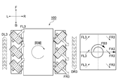
図1乃至図3、図6に示すように、一対の帯状駆動体120、120の速度ベクトルDR3、DL3の大きさが相互に等しいとともに速度ベクトルDR3の向きが後退方向Bに一致し、しかも速度ベクトルDL3の向きが前進方向Fに一致している場合、各回転体130の外周面130Sから移動面Pに作用する作用力ベクトルFR3、FL3の和である合力ベクトルFA3の向きが右進行方向Rに一致する。
このとき、合力ベクトルFA3に応じて移動面Pから多方向移動体モジュール100に作用する反作用力FB3の向きが時計回り方向に一致する。
その結果、多方向移動体モジュール100は、時計回り方向に回転駆動される。
このとき、合力ベクトルFA3に応じて移動面Pから多方向移動体モジュール100に作用する反作用力FB3の向きが時計回り方向に一致する。
その結果、多方向移動体モジュール100は、時計回り方向に回転駆動される。
図1乃至図3、図7に示すように、一対の帯状駆動体120、120の速度ベクトルDR4、DL4の大きさが相互に等しいとともに速度ベクトルDR4の向きが前進方向Fに一致し、しかも速度ベクトルDL4の向きが後退方向Bに一致している場合、各回転体130の外周面130Sから移動面Pに作用する作用力ベクトルFR4、FL4の和である合力ベクトルFA4の向きが左進行方向Lに一致する。
このとき、合力ベクトルFA4に応じて移動面Pから多方向移動体モジュール100に作用する反作用力FB4の向きが反時計回り方向に一致する。
その結果、多方向移動体モジュール100は、反時計回り方向に回転駆動される。
このとき、合力ベクトルFA4に応じて移動面Pから多方向移動体モジュール100に作用する反作用力FB4の向きが反時計回り方向に一致する。
その結果、多方向移動体モジュール100は、反時計回り方向に回転駆動される。
図1乃至図3、図8に示すように、一対の帯状駆動体120、120の一方の速度ベクトルの大きさがゼロである場合、より具体的には、他方の駆動チェーン120の速度ベクトルDL5のみの大きさがゼロでないとともにその向きが後退方向Bに一致している場合、他方の駆動チェーン120に設けられた各回転体130の外周面130Sから移動面Pに作用力ベクトルFL5が作用する。
また、一方の駆動チェーン120に設けられた回転体130は、移動体モジュール本体110の荷重を逃がす。
このとき、実質的な合力ベクトルFA5の大きさが作用力ベクトルFL5の大きさより大きくなるとともにその向きが左進行方向L及び後退方向Bのそれぞれに対して45°を形成する向きに一致する。
加えて、合力ベクトルFA5に応じて移動面Pから多方向移動体モジュール100に作用する反作用力FB5の向きが、右進行方向R及び前進方向Fのそれぞれに対して45°を形成する向きに一致する。
その結果、多方向移動体モジュール100は、反作用力FB5の向きすなわち右進行方向R及び前進方向Fのそれぞれに対して45°を形成する向きに移動する。
また、一方の駆動チェーン120に設けられた回転体130は、移動体モジュール本体110の荷重を逃がす。
このとき、実質的な合力ベクトルFA5の大きさが作用力ベクトルFL5の大きさより大きくなるとともにその向きが左進行方向L及び後退方向Bのそれぞれに対して45°を形成する向きに一致する。
加えて、合力ベクトルFA5に応じて移動面Pから多方向移動体モジュール100に作用する反作用力FB5の向きが、右進行方向R及び前進方向Fのそれぞれに対して45°を形成する向きに一致する。
その結果、多方向移動体モジュール100は、反作用力FB5の向きすなわち右進行方向R及び前進方向Fのそれぞれに対して45°を形成する向きに移動する。
図1乃至図3、図9に示すように、一対の帯状駆動体120、120の速度ベクトルDR6の大きさがゼロではなく且つ速度ベクトルDL6の大きさより小さいとともに速度ベクトルDR6の向きが前進方向Fに一致し、しかも速度ベクトルDL6の向きが後退方向Bに一致している場合、各回転体130の外周面130Sから移動面Pに作用力ベクトルFR6、FL6が作用する。
このとき、作用力ベクトルFR6、FL6の和である合力ベクトルFA6に応じて時計回り方向を斜めに偏向した方向に反作用力FB6が生じる。
その結果、多方向移動体モジュール100は、偏向した方向に生じる反作用力FB6に応じて回動される。
このとき、作用力ベクトルFR6、FL6の和である合力ベクトルFA6に応じて時計回り方向を斜めに偏向した方向に反作用力FB6が生じる。
その結果、多方向移動体モジュール100は、偏向した方向に生じる反作用力FB6に応じて回動される。
図1乃至図3、図10に示すように、一対の帯状駆動体120、120の速度ベクトルDR7の大きさがゼロではなく且つ速度ベクトルDL7の大きさより小さいとともに速度ベクトルDR7の向きが後退方向Bに一致し、しかも速度ベクトルDL7の向きが後退方向Bに一致している場合、各回転体130の外周面130Sから移動面Pに作用力ベクトルFR7、FL7が作用する。
このとき、作用力ベクトルFR7、FL7の和である合力ベクトルFA7に応じて時計回り方向を斜めに偏向した方向に反作用力FB7が生じる。
その結果、多方向移動体モジュール100は、偏向した方向に生じる反作用力FB7に応じて回動される。
このとき、作用力ベクトルFR7、FL7の和である合力ベクトルFA7に応じて時計回り方向を斜めに偏向した方向に反作用力FB7が生じる。
その結果、多方向移動体モジュール100は、偏向した方向に生じる反作用力FB7に応じて回動される。
このようにして得られた本実施例の多方向移動体モジュール100は、移動体モジュール本体110と一対の帯状駆動体120、120と複数の回転体130とを備えていることにより、各回転体130における外周面130Sの摩耗と移動体モジュール本体110の重心を高い位置に設計変更することによる多方向移動体モジュール100の大型化すなわちサイズ増大と移動面Pや回転体130における外周面130Sの損傷とを防ぐとともに移動面Pに沿って多方向に円滑且つ自在に移動体モジュール本体110を移動できるなど、その効果は甚大である。
100 ・・・ 多方向移動体モジュール
110 ・・・ 移動体モジュール本体
120 ・・・ 帯状駆動体
130 ・・・ 回転体
130S ・・・ 回転体の外周面
131 ・・・ 回転軸
131A ・・・ 回転軸線
140LF、140LB、140RF、140RB ・・・ 動力伝達用回転体
141LF、141LB、141RF、141RB ・・・ 駆動軸
142F、142B ・・・ 駆動モータ
D ・・・ 帯状駆動体部分の速度ベクトル
DR1、DR2、DR3、DR4、DR6、DR7 ・・・ 右側に設けられた帯状駆動体部分の速度ベクトル
DL1、DL2、DL3、DL4、DL5、DL6、DL7 ・・・ 左側に設けられた帯状駆動体部分の速度ベクトル
FR1、FR2、FR3、FR4、FR6、FR7 ・・・ 右側回転体の作用力
FL1、FL2、FL3、FL4、FL5、FL6、FL7 ・・・ 左側回転体の作用力
FA1、FA2、FA3、FA4、FA5、FA6、FA7 ・・・ 合力ベクトル
FB1、FB2、FB3、FB4、FB5、FB6、FB7 ・・・ 反作用力
P ・・・ 多方向移動体モジュールの移動面
F ・・・ 多方向移動体モジュールの前進方向
B ・・・ 多方向移動体モジュールの後退方向
R ・・・ 多方向移動体モジュールの右進行方向
L ・・・ 多方向移動体モジュールの左進行方向
110 ・・・ 移動体モジュール本体
120 ・・・ 帯状駆動体
130 ・・・ 回転体
130S ・・・ 回転体の外周面
131 ・・・ 回転軸
131A ・・・ 回転軸線
140LF、140LB、140RF、140RB ・・・ 動力伝達用回転体
141LF、141LB、141RF、141RB ・・・ 駆動軸
142F、142B ・・・ 駆動モータ
D ・・・ 帯状駆動体部分の速度ベクトル
DR1、DR2、DR3、DR4、DR6、DR7 ・・・ 右側に設けられた帯状駆動体部分の速度ベクトル
DL1、DL2、DL3、DL4、DL5、DL6、DL7 ・・・ 左側に設けられた帯状駆動体部分の速度ベクトル
FR1、FR2、FR3、FR4、FR6、FR7 ・・・ 右側回転体の作用力
FL1、FL2、FL3、FL4、FL5、FL6、FL7 ・・・ 左側回転体の作用力
FA1、FA2、FA3、FA4、FA5、FA6、FA7 ・・・ 合力ベクトル
FB1、FB2、FB3、FB4、FB5、FB6、FB7 ・・・ 反作用力
P ・・・ 多方向移動体モジュールの移動面
F ・・・ 多方向移動体モジュールの前進方向
B ・・・ 多方向移動体モジュールの後退方向
R ・・・ 多方向移動体モジュールの右進行方向
L ・・・ 多方向移動体モジュールの左進行方向
Claims (5)
- 移動面に沿って移動する移動体モジュール本体と、
前記移動体モジュール本体に設けられているとともに相互に独立して進退自在に駆動される一対の帯状駆動体と、
前記帯状駆動体の駆動方向に沿って前記帯状駆動体に配列されているとともに前記帯状駆動体の駆動方向に対して斜交する回転軸がそれぞれ平行となるように軸着された状態で前記移動面に外周面をそれぞれ接触させる複数の回転体とを備えていることを特徴とする多方向移動体モジュール。 - 前記一対の帯状駆動体のそれぞれの駆動方向が、相互に平行であることを特徴とする請求項1に記載の多方向移動体モジュール。
- 前記一対の帯状駆動体の一方に設けられた回転体の回転軸線と前記一対の帯状駆動体の他方に設けられた回転体の回転軸線とが、相互に交差していることを特徴とする請求項2に記載の多方向移動体モジュール。
- 前記一対の帯状駆動体の一方に設けられた回転体の回転軸と前記一対の帯状駆動体の他方に設けられた回転体の回転軸とが、前記帯状駆動体の駆動方向に対して45°の角度を形成していることを特徴とする請求項3に記載の多方向移動体モジュール。
- 前記一対の帯状駆動体が、前記一対の帯状駆動体のそれぞれに対応して前記移動体モジュール本体に設けられた動力伝達用回転体に巻き掛けられた状態で進退自在に駆動される無端形状をそれぞれ形成していることを特徴とする請求項1乃至請求項4のいずれか一つに記載の多方向移動体モジュール。
Applications Claiming Priority (2)
| Application Number | Priority Date | Filing Date | Title |
|---|---|---|---|
| JP2011-174140 | 2011-08-09 | ||
| JP2011174140 | 2011-08-09 |
Publications (1)
| Publication Number | Publication Date |
|---|---|
| WO2013022013A1 true WO2013022013A1 (ja) | 2013-02-14 |
Family
ID=47668519
Family Applications (1)
| Application Number | Title | Priority Date | Filing Date |
|---|---|---|---|
| PCT/JP2012/070149 Ceased WO2013022013A1 (ja) | 2011-08-09 | 2012-08-08 | 多方向移動体モジュール |
Country Status (1)
| Country | Link |
|---|---|
| WO (1) | WO2013022013A1 (ja) |
Citations (3)
| Publication number | Priority date | Publication date | Assignee | Title |
|---|---|---|---|---|
| JPH0717442A (ja) * | 1993-06-30 | 1995-01-20 | Shigeo Hirose | 全方向移動用車両 |
| JP2004344435A (ja) * | 2003-05-22 | 2004-12-09 | Japan Science & Technology Agency | パワーアシスト型移動台車 |
| WO2008132778A1 (ja) * | 2007-04-20 | 2008-11-06 | Honda Motor Co., Ltd. | 全方向駆動装置及びそれを用いた全方向移動車 |
-
2012
- 2012-08-08 WO PCT/JP2012/070149 patent/WO2013022013A1/ja not_active Ceased
Patent Citations (3)
| Publication number | Priority date | Publication date | Assignee | Title |
|---|---|---|---|---|
| JPH0717442A (ja) * | 1993-06-30 | 1995-01-20 | Shigeo Hirose | 全方向移動用車両 |
| JP2004344435A (ja) * | 2003-05-22 | 2004-12-09 | Japan Science & Technology Agency | パワーアシスト型移動台車 |
| WO2008132778A1 (ja) * | 2007-04-20 | 2008-11-06 | Honda Motor Co., Ltd. | 全方向駆動装置及びそれを用いた全方向移動車 |
Similar Documents
| Publication | Publication Date | Title |
|---|---|---|
| JP2014196004A (ja) | 多方向移動体モジュール | |
| CN112024414B (zh) | 分拣机 | |
| CN109476429B (zh) | 引导模块及具备该引导模块的驱动装置 | |
| CN101657347A (zh) | 全方向驱动装置以及使用该全方向驱动装置的全方向移动车 | |
| WO2014043841A1 (zh) | 履带式全方位移动平台 | |
| KR102429696B1 (ko) | 험지 주행 및 장애물 극복이 가능한 모바일 로봇의 바퀴 장치 및 이를 포함하는 모바일 로봇 | |
| EP1832445B1 (en) | Universal transmission roller wheel | |
| JP5910426B2 (ja) | 全方向車輪、全方向車輪ユニット及び移動体 | |
| KR20150014057A (ko) | 전방향 무한궤도륜 및 이를 이용한 전방향 이동차량 | |
| JP6629567B2 (ja) | 搬送装置 | |
| JP5305285B2 (ja) | 球体駆動式全方向移動装置 | |
| JP2006341710A (ja) | クローラ型走行装置 | |
| KR102230230B1 (ko) | 실내 주행 로봇 | |
| US10087005B1 (en) | Shunting transmission device and shunting transmission method using the same | |
| WO2013022017A1 (ja) | 多方向移動体モジュール | |
| JP5917442B2 (ja) | 無人搬送車 | |
| JPWO2015156263A1 (ja) | 移動搬送機構 | |
| WO2013022013A1 (ja) | 多方向移動体モジュール | |
| KR101444782B1 (ko) | 구동모듈을 포함하는 이동체 | |
| WO2013141017A1 (ja) | 多方向移動体モジュール | |
| JPS63149270A (ja) | 搬送車 | |
| KR102597420B1 (ko) | 모듈형 듀얼 스위블 휠 및 이를 포함하는 플랫폼 | |
| JP5717149B2 (ja) | 無人搬送車 | |
| TWM661680U (zh) | 傳動機構 | |
| CN108016518A (zh) | 一种新式麦轮履带车 |
Legal Events
| Date | Code | Title | Description |
|---|---|---|---|
| 121 | Ep: the epo has been informed by wipo that ep was designated in this application |
Ref document number: 12821584 Country of ref document: EP Kind code of ref document: A1 |
|
| NENP | Non-entry into the national phase |
Ref country code: DE |
|
| 122 | Ep: pct application non-entry in european phase |
Ref document number: 12821584 Country of ref document: EP Kind code of ref document: A1 |
|
| NENP | Non-entry into the national phase |
Ref country code: JP |