WO2013015405A1 - 荷重測定センサの支持構造 - Google Patents
荷重測定センサの支持構造 Download PDFInfo
- Publication number
- WO2013015405A1 WO2013015405A1 PCT/JP2012/069117 JP2012069117W WO2013015405A1 WO 2013015405 A1 WO2013015405 A1 WO 2013015405A1 JP 2012069117 W JP2012069117 W JP 2012069117W WO 2013015405 A1 WO2013015405 A1 WO 2013015405A1
- Authority
- WO
- WIPO (PCT)
- Prior art keywords
- sensor
- load
- insertion hole
- width direction
- annular
- Prior art date
- Legal status (The legal status is an assumption and is not a legal conclusion. Google has not performed a legal analysis and makes no representation as to the accuracy of the status listed.)
- Ceased
Links
Images














Classifications
-
- G—PHYSICS
- G01—MEASURING; TESTING
- G01D—MEASURING NOT SPECIALLY ADAPTED FOR A SPECIFIC VARIABLE; ARRANGEMENTS FOR MEASURING TWO OR MORE VARIABLES NOT COVERED IN A SINGLE OTHER SUBCLASS; TARIFF METERING APPARATUS; MEASURING OR TESTING NOT OTHERWISE PROVIDED FOR
- G01D11/00—Component parts of measuring arrangements not specially adapted for a specific variable
- G01D11/30—Supports specially adapted for an instrument; Supports specially adapted for a set of instruments
-
- B—PERFORMING OPERATIONS; TRANSPORTING
- B60—VEHICLES IN GENERAL
- B60N—SEATS SPECIALLY ADAPTED FOR VEHICLES; VEHICLE PASSENGER ACCOMMODATION NOT OTHERWISE PROVIDED FOR
- B60N2/00—Seats specially adapted for vehicles; Arrangement or mounting of seats in vehicles
- B60N2/02—Seats specially adapted for vehicles; Arrangement or mounting of seats in vehicles the seat or part thereof being movable, e.g. adjustable
- B60N2/04—Seats specially adapted for vehicles; Arrangement or mounting of seats in vehicles the seat or part thereof being movable, e.g. adjustable the whole seat being movable
- B60N2/06—Seats specially adapted for vehicles; Arrangement or mounting of seats in vehicles the seat or part thereof being movable, e.g. adjustable the whole seat being movable slidable
- B60N2/07—Slide construction
- B60N2/0722—Constructive details
- B60N2/0732—Attachment of seat frame to the slide, e.g. eyelets
-
- B—PERFORMING OPERATIONS; TRANSPORTING
- B60—VEHICLES IN GENERAL
- B60N—SEATS SPECIALLY ADAPTED FOR VEHICLES; VEHICLE PASSENGER ACCOMMODATION NOT OTHERWISE PROVIDED FOR
- B60N2/00—Seats specially adapted for vehicles; Arrangement or mounting of seats in vehicles
- B60N2/002—Seats provided with an occupancy detection means mounted therein or thereon
- B60N2/0021—Seats provided with an occupancy detection means mounted therein or thereon characterised by the type of sensor or measurement
- B60N2/0024—Seats provided with an occupancy detection means mounted therein or thereon characterised by the type of sensor or measurement for identifying, categorising or investigation of the occupant or object on the seat
-
- B—PERFORMING OPERATIONS; TRANSPORTING
- B60—VEHICLES IN GENERAL
- B60N—SEATS SPECIALLY ADAPTED FOR VEHICLES; VEHICLE PASSENGER ACCOMMODATION NOT OTHERWISE PROVIDED FOR
- B60N2/00—Seats specially adapted for vehicles; Arrangement or mounting of seats in vehicles
- B60N2/002—Seats provided with an occupancy detection means mounted therein or thereon
- B60N2/0021—Seats provided with an occupancy detection means mounted therein or thereon characterised by the type of sensor or measurement
- B60N2/003—Seats provided with an occupancy detection means mounted therein or thereon characterised by the type of sensor or measurement characterised by the sensor mounting location in or on the seat
- B60N2/0031—Seats provided with an occupancy detection means mounted therein or thereon characterised by the type of sensor or measurement characterised by the sensor mounting location in or on the seat mounted on the frame
-
- B—PERFORMING OPERATIONS; TRANSPORTING
- B60—VEHICLES IN GENERAL
- B60N—SEATS SPECIALLY ADAPTED FOR VEHICLES; VEHICLE PASSENGER ACCOMMODATION NOT OTHERWISE PROVIDED FOR
- B60N2/00—Seats specially adapted for vehicles; Arrangement or mounting of seats in vehicles
- B60N2/68—Seat frames
- B60N2/682—Joining means
-
- G—PHYSICS
- G01—MEASURING; TESTING
- G01L—MEASURING FORCE, STRESS, TORQUE, WORK, MECHANICAL POWER, MECHANICAL EFFICIENCY, OR FLUID PRESSURE
- G01L1/00—Measuring force or stress, in general
-
- B—PERFORMING OPERATIONS; TRANSPORTING
- B60—VEHICLES IN GENERAL
- B60N—SEATS SPECIALLY ADAPTED FOR VEHICLES; VEHICLE PASSENGER ACCOMMODATION NOT OTHERWISE PROVIDED FOR
- B60N2210/00—Sensor types, e.g. for passenger detection systems or for controlling seats
- B60N2210/40—Force or pressure sensors
- B60N2210/42—Strain gauges
Definitions
- the present invention relates to a support structure for supporting a load measurement sensor, and in particular, a support structure for supporting a load measurement sensor on a support bracket in a state where an extending shaft portion provided in the load measurement sensor is positioned on the side of the sensor body.
- a support structure for supporting a load measurement sensor on a support bracket in a state where an extending shaft portion provided in the load measurement sensor is positioned on the side of the sensor body.
- a technology for controlling the operation of peripheral devices for vehicle seats according to the weight of the passengers seated has been proposed.
- a load measuring sensor is disposed below a vehicle seat on which the occupant is seated.
- the position of the load measuring sensor is generally arranged below the vehicle seat.
- a slide rail provided to slide the vehicle seat in the front-rear direction and a seat constituting the vehicle seat Some are arranged between frames (Patent Document 1).
- FIG. 26 is a partial perspective view showing a vehicle seat to which the load measuring sensor support structure according to the conventional example is applied.
- FIG. 27 is a cross-sectional view of a load measuring sensor support structure according to a conventional example.
- Patent Document 2 a technique has been proposed in which the axial direction of the shaft portion for supporting the load measuring sensor is arranged in the horizontal direction instead of the vertical direction (Patent Document 2).
- a load measuring sensor (described as “weight detection sensor” in Patent Document 2) is attached such that the axial direction is a horizontal direction so that it falls within the height range of the seat frame. Since the load measuring sensor is disposed on the vehicle seat, the height of the vehicle seat can be made lower than that of the technique of Patent Document 1.
- each end When supporting both ends of the load measurement sensor in the axial direction so that the axial direction of the shaft is horizontal, each end is assembled to the support bracket, and the load measurement sensor is quickly supported by the support bracket. Becomes difficult. For this reason, as a method for supporting the load measurement sensor, for example, it is conceivable that only one end portion in the axial direction of the load measurement sensor is supported by the support bracket. However, if the support rigidity of the support bracket is small, the position of the load measurement sensor is not stable, and the measurement accuracy of the load measurement sensor may be affected.
- the present invention has been made in view of the above-described problems, and the object of the present invention is to secure the rigidity of the support bracket that supports the load measurement sensor and to stabilize the arrangement position of the load measurement sensor. It is to realize a possible support structure. Another object of the present invention is to provide a support structure that can reliably transmit an input load from the seat side to a load measurement sensor and accurately detect the input load.
- the object is to provide a load measurement sensor including a sensor main body that detects a load applied to a seat, and an extending shaft portion that extends from a side of the sensor main body.
- a load measurement sensor support structure that is supported by a support bracket in a state where the extension shaft portion is located on a side of the sensor body, and the support bracket is configured to support the load measurement sensor when the load measurement sensor is supported.
- a standing wall part in which an insertion hole into which the output shaft part is inserted is formed; a bottom wall part that intersects the standing wall part and is in contact with the standing wall part at one end part in the width direction of the seat; An upper projecting wall provided at a position opposite to the standing wall portion, in contact with the bottom wall portion at the other end opposite to the side where the standing wall portion is located in the width direction. It is solved by being provided.
- the support bracket since the support bracket includes an upward projecting wall that faces the upright wall portion, sufficient rigidity is secured to the support bracket. As a result, the position of the load measurement sensor can be stabilized, and thus the load measurement sensor can be maintained in a state where accurate load measurement is performed.
- the support bracket extends along the front-rear direction of the seat, and the upper projecting wall is formed from the front end to the rear end of the bottom wall portion.
- the load measuring sensor is attached from the inside of the support bracket, that is, from the side where the upper protruding wall is provided.
- the load measurement sensor can be smoothly passed through the removal portion without being blocked by the upper protruding wall. It comes to be arranged in a support position. As a result, the load measuring sensor can be supported more easily.
- the seat is mounted on a rail member extending along the front-rear direction of the seat via the support bracket, and the support bracket is separate from the rail member. It is preferable that it is detachably fixed to the rail member.
- the support bracket is fixed to the rail member by a fastening member, and the fastening member is set at a position avoiding the load measuring sensor in the front-rear direction. is there.
- the fixing position of the support bracket in the rail member is adjustable along the longitudinal direction of the rail member. With such a configuration, it is possible to easily and accurately adjust the mounting position of the support bracket.
- the sensor body includes a deforming portion that receives the load and deforms so as to bend inward in the radial direction of the extending shaft portion, and comes into contact with the load measuring sensor to load the load.
- a load input unit that inputs to the load measurement sensor, and a sensor body receiving unit to which the deformation unit is pressed when the load measurement sensor moves due to the load input from the load input unit
- the sensor main body receiving portion includes the support bracket as a constituent element, and the load input portion and the sensor main body receiving portion are separated from each other in a state where the load measuring sensor is supported by the support bracket. is there.
- the load input unit and the sensor body receiving unit are located at a distance from each other, when a load is input from the load input unit to the load measurement sensor, the load measurement sensor moves.
- the deforming part is pressed against the sensor body receiving part via the contact part and deformed.
- the input load from the load input unit is reliably transmitted to the sensor main body, more specifically to the deformed unit via the contact unit.
- the load is appropriately transmitted from the load input part to the deformed part by the lever principle. As a result, the input load from the load input unit can be appropriately transmitted to the deformed unit, and the load can be accurately detected.
- the load measurement sensor is rotated by the load input from the load input unit, and the deformation unit is pressed against the sensor body by the rotation of the load measurement sensor.
- the load measuring sensor is moved and supported by the support bracket, the load input portion and the sensor body receiving portion are separated from each other in the axial direction of the extending shaft portion. It becomes possible to exhibit the effect of invention described in (2) more effectively.
- the load input portion in the state where the load measuring sensor is supported by the support bracket, the load input portion is positioned on the side opposite to the sensor body when viewed from the sensor body receiving portion in the axial direction. It is preferable to do so.
- the load input unit is separated from the sensor main body, even if an excessive load is input from the load input unit, the load does not directly act on the sensor main body, so that the sensor main body is protected. It becomes possible.
- the deforming portion is an annular portion that is inserted into the insertion hole and is distorted in a radial direction when pressed against the inner peripheral surface of the insertion hole
- the sensor body receiving portion is A sliding member located between the inner peripheral surface of the insertion hole and the outer peripheral surface of the annular portion in the radial direction and capable of sliding on the outer peripheral surface of the annular portion;
- the seat includes a side frame that is spaced apart in the width direction of the seat, and the standing wall portion is disposed at a position aligned with the side frame in the axial direction. It is preferable that a portion of the standing wall portion located at a position lower than the insertion hole extends downward along the vertical direction.
- the support bracket constitutes at least a part of a rail member on which the seat is placed. Since the rail member has a relatively high rigidity, if at least a part of the rail member is configured by the sensor body receiving portion as described above, the rigidity of the sensor body receiving portion is ensured, and as a result, the deformed portion can be stably provided in the sensor body. It comes to press against the receiving part.
- the upright wall portion includes an annular portion that is formed inside the insertion hole and protrudes in the width direction of the seat, and the load is input by the load input from the load input portion. It is preferable that the deforming portion presses against the inner peripheral surface of the insertion hole when the measurement sensor moves. As described above, since the area of the inner peripheral surface of the insertion hole against which the deformed portion is pressed is increased by the amount corresponding to the annular portion, the deformed portion is easily pressed against the inner peripheral surface of the insertion hole, and as a result, the load on the deformed portion is reduced. Is easily transmitted.
- the annular portion protrudes toward the side where the load input portion is located in the width direction as in the thirteenth aspect. If the annular part protrudes toward the side where the load input part is located, when the load measurement sensor is rotated by the load input from the load input part and the deformed part is pressed against the inner peripheral surface of the insertion hole, First, since it comes to press against the inner peripheral surface on the base end side having higher rigidity in the annular portion, the deformable portion can be appropriately pressed against the sensor body receiving portion.
- the annular portion may protrude toward the opposite side to the side where the load input portion is located in the width direction. If the annular part protrudes toward the side opposite to the side where the load input part is located, the load measuring sensor is rotated by the load input from the load input part and the deformed part is pushed against the inner peripheral surface of the insertion hole. When hitting, it first presses against the inner peripheral surface of the insertion hole on the free end side of the annular portion.
- the free end portion bends and deforms due to the deformable portion pressing against the inner peripheral surface of the insertion hole on the free end side of the annular portion, and the deformable portion It is possible to absorb the overload by releasing the impact load generated by the collision with the annular portion.
- the deforming portion is an annular portion that is inserted into the insertion hole and is distorted in a radial direction by pressing against the inner peripheral surface of the insertion hole
- the sensor body receiving portion is A sliding member located between the inner peripheral surface of the insertion hole and the outer peripheral surface of the annular portion in the radial direction and capable of sliding on the outer peripheral surface of the annular portion;
- the sliding member is configured by inserting the base material into the annular part and caulking one end part protruding from the annular part. And the collar part formed by crimping the one end part which protruded from the annular part among sliding members comes to adjoin the front-end
- the deforming portion is an annular portion that is inserted into the insertion hole and is distorted in the radial direction when pressed against the inner peripheral surface of the insertion hole
- the sensor body is An inner portion positioned on the inner side of the annular portion, and the inner portion has an inner large-diameter region that comes into contact with the annular portion when the annular portion is distorted inward in the radial direction, An inner portion small-diameter region that is adjacent to the inner-portion large-diameter region and has a smaller diameter than the inner-portion large-diameter region, and in the state where the load measuring sensor is supported by the support bracket, It is preferable that the large-diameter region and at least a part of the inner-side small-diameter region are disposed in the insertion hole.
- the load is transmitted to the portion of the annular portion that is distorted in the radial direction and abuts against the inner large-diameter region, the inner large-diameter region and the inner small-diameter region are supported with the load measurement sensor supported by the support bracket. If at least a part of the ring portion is disposed in the insertion hole, the entire portion of the annular portion where the load is transmitted is surrounded by the annular portion. As a result, the portion of the annular portion to which the load is transmitted reliably presses against the annular portion, and the load is reliably transmitted.
- the seat includes a side frame that is spaced apart in the width direction of the seat, and the support bracket is positioned on the inner side of the side frame in the width direction, It is preferable that the distal end portion of the extending shaft portion protrudes from the insertion hole and is fastened to the side frame. As described above, the extension shaft portion is fastened to the relatively rigid side frame in the frame included in the seat, so that the load measuring sensor can be stably disposed at the support position. .
- the first aspect of the present invention sufficient rigidity is imparted to the support bracket on which the load measurement sensor is supported, so that the position of the load measurement sensor can be stabilized.
- the invention of claim 2 it is possible to shift the support position of the load measuring sensor further downward.
- the versatility of the support structure of the load measurement sensor is improved, such as being able to easily reattach the load measurement sensor even when the seat design is changed, and maintenance is also possible. Also improve.
- Claim 4 as a result of suppressing interference with a load measurement sensor and a fastening member, it becomes possible to shift the support position of a load measurement sensor further below, Therefore, a sheet
- the deformed portion is appropriately displaced by the displacement of the load input from the load input portion to a position where the load is pressed against the sensor body receiving portion as the load measuring sensor rotates. Even if the load input from the load input portion is very small, the load is appropriately transmitted from the load input portion to the deformed portion by the lever principle. As described above, the load input from the load input unit can be appropriately transmitted to the deforming unit, so that the load can be accurately detected. According to the invention described in claim 7, the effect of the invention described in claim 6 can be exhibited more effectively.
- the eighth aspect of the present invention even if an excessive load is input from the load input portion, the excessive load does not directly act on the sensor body, so that the sensor body can be protected. It becomes.
- the ninth aspect of the present invention it is possible to prevent the force acting on the flange portion of the sliding member from becoming unbalanced between the flange portions when the annular portion contacts the sliding member. It becomes. Moreover, the mounting operation of the sliding member is facilitated.
- the tenth aspect of the present invention it is possible to suppress the sheet from becoming large due to the standing wall portion spreading in the width direction of the sheet.
- the rigidity of the sensor main body receiving part is ensured, and the deformed part is stably pressed against the sensor main body receiving part.
- the deformable portion since the area of the inner peripheral surface of the insertion hole against which the deformable portion is pressed is expanded by the amount of the annular portion, the deformable portion is likely to press against the inner peripheral surface of the insert hole, The load is easily transmitted to the deformed portion.
- the deformed portion can be appropriately pressed against the sensor main body receiving portion because it is pressed against the inner peripheral surface on the base end side having higher rigidity.
- the annular portion is free. Press against the inner peripheral surface of the insertion hole on the end side.
- the deformed portion will press against the inner peripheral surface of the insertion hole on the free end side of the annular portion. It is possible to absorb the above-mentioned excessive load by escaping the impact load generated by the collision between the deformed portion and the annular portion.
- the caulking process is performed on one end portion of the base material protruding from the annular portion in order to form the flange portion at one end portion in the sliding direction of the sliding member, An allowance can be ensured by the amount protruding beyond the outer edge of the tip of the part.
- the portion to which the load is transmitted is annular in the annular portion. It will surely press against the part and the load will be transmitted reliably.
- the extension shaft portion is fastened to the relatively rigid side frame, whereby the load measuring sensor can be stably arranged at the support position.
- FIG. It is an enlarged view which shows the periphery of a load measurement sensor in FIG. It is a figure which shows the modification of the support structure of a load measurement sensor. It is an enlarged view around a hole of a side frame. It is a figure which shows the positional relationship between a load measurement sensor and S spring. It is a figure which shows the positional relationship between a load measurement sensor and a submarine suppression pipe. It is sectional drawing which shows the example of improvement of an extension shaft part. It is a perspective view which shows the seat unit which concerns on other embodiment. It is an expanded view of the seat unit which concerns on other embodiment. It is a figure which shows the support structure of the load measurement sensor which concerns on other embodiment.
- the load measurement sensor of the present embodiment measures a load applied to the vehicle seat Z, and in the following description, a support for supporting the load measurement sensor on a predetermined member in a predetermined posture.
- the structure will be described.
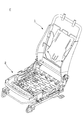
- FIG. 1 is an external view of a vehicle seat.
- FIG. 2 is a perspective view of the seat frame.
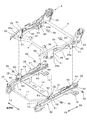
- FIG. 3 is a perspective view showing the seat unit.
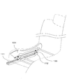
- FIG. 4 is a development view of the seat unit.
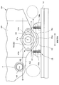
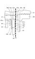
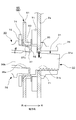
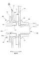
- FIG. 5 is a view showing a support structure of the load measuring sensor, and is a view showing a cross section around the load measuring sensor.
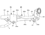
- 6 and 7 are perspective views showing the side frame, FIG. 6 shows the inner surface of the side frame, and FIG. 7 shows the outer surface of the side frame.
- FIG. 8 is a perspective view showing a rail member.
- FIG. 9 is a diagram illustrating a state in which the mounting bracket and the side frame are coupled to each other.
- FIG. 10 is a side view of the load measuring sensor supported at a predetermined position.
- FIG. 11 is a component diagram showing each of the sensor mounting components.
- FIG. 12 is an enlarged view showing the periphery of the load measuring sensor in FIG.
- FIG. 13 is a view showing a modified example of the support structure of the load measuring sensor, and corresponds to FIG.
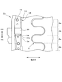
- FIG. 14 is an enlarged view around the hole portion of the side frame.
- FIG. 15 is a diagram illustrating a positional relationship between the load measurement sensor and the S spring.
- FIG. 16 is a diagram illustrating a positional relationship between the load measurement sensor and the submarine suppression pipe.
- FIG. 17 is a cross-sectional view showing an improved example of the extending shaft portion.
- the width direction of the vehicle seat Z (hereinafter simply referred to as the width direction) is the left-right direction in a state of facing the front of the vehicle, and corresponds to the horizontal direction. Further, in FIG. 4, for the convenience of illustration, illustration of a later-described sensor mounting component 40 is omitted.
- the load measuring sensor (hereinafter referred to as sensor 30) mainly measures the load when the occupant is seated on the vehicle seat Z as the load applied to the vehicle seat Z.
- the measurement result is output from the substrate in the sensor 30 as an electrical signal.
- a receiver (not shown) receives the output signal, a determination is made as to whether or not the passenger is present and whether the seated passenger is an adult or a child.
- Vehicle seat structure In order to measure the load applied to the vehicle seat Z, the sensor 30 is supported at a predetermined position of the seat unit S shown in FIG. Below, the structure of the seat unit S including the vehicle seat Z will be outlined.
- the seat unit S includes a vehicle seat Z and a rail member 10, and is fixed to the vehicle body floor.
- a vehicle seat Z shown in FIG. 1 is an example of a seat, and includes a seat frame F and a cushion body as its skeleton.
- the seat frame F is made of a metal material, and as shown in FIG. 2, a seat frame 2 having side frames 2a at both ends in the width direction and a seat back frame 1 on the back side.
- Each side frame 2a constituting the seating frame 2 is a sheet metal member extending in the front-rear direction, and is connected to the seat back frame at the rear end. Further, the side frame 2a on the one end side in the width direction and the side frame 2a on the other end side in the width direction are separated from each other in the width direction in a parallel state. Further, as shown in FIG. 4, the side frames 2 a are connected to each other via the connection pipe 3 on the rear end side, and are also connected to each other on the front end side via the submarine suppression pipe 4.
- the submarine suppression pipe 4 as a connecting member is a pipe member extending from one end in the width direction to the other end. While the width direction center part 4a and the width direction edge part 4b of the submarine suppression pipe 4 are located in parallel along the width direction, they are displaced in the front-rear direction. In this embodiment, the width direction center part 4a Is located behind the widthwise end 4b (see, for example, FIG. 16). However, it is not limited to this, The structure where the width direction edge part 4b is located in the rear side rather than the width direction center part 4a may be sufficient. In addition, between both the width direction center part 4a and the width direction edge part 4b, the connection part 4c which connects between the both is provided, and the extension direction of the connection part 4c inclines with respect to the width direction.
- each S spring 6 is a support spring that supports the cushion body from below, and extends in the front-rear direction while meandering.
- the front end part of each S spring 6 is hung on the erection pan 5 as a plate-like frame erected between the side frames 2a.
- the rear end portion of each S spring 6 is hung on the above-described connecting pipe 3, more specifically, a substantially arc-shaped retaining member fitted to the connecting pipe 3.
- each S spring 6 is arrange
- a cushion body (not shown) is mounted on the installation pan 5 and the S spring 6. The structure of the side frame 2a will be described in detail later.
- the erection pan 5 is attached to the side frame 2a by an attachment portion 5a. And this attachment part 5a is arrange
- the mounting portion 5a of the installation pan 5 is disposed at a position avoiding a front mounting region 25 described later.
- a pair of rail members 10 are provided apart from each other in the width direction.
- Each rail member 10 has a lower rail 11 fixed to the vehicle body floor, and an upper rail 12 that engages with the lower rail 11 and can slide on the lower rail 11.
- Each of the lower rail 11 and the upper rail 12 is provided in pairs, and each extends along the front-rear direction. As shown in FIG. 4, the pair of upper rails 12 are arranged in parallel with each other at an interval in the width direction, and are connected by a slide lever 17 therebetween.
- the pair of lower rails 11 are arranged in parallel with each other at an interval in the left-right direction, and are connected by a member frame 14 therebetween.
- a fixed bracket 13 is attached to the lower surface of each end portion of the lower rail 11. When the fixing bracket 13 is fastened to the vehicle body floor, the lower rail 11 is fixed to the vehicle body floor.
- a vehicle seat Z is placed on each of the lower rails 11. More specifically, the upper rail 12 is slidably disposed on the lower rail 11, and the mounting brackets 15 and 16 are further screwed onto the bolts 18a and 18b and the bolts 18a and 18b as fastening members on the upper rail 12, respectively. It is fixed at.
- the vehicle seat Z is attached to each upper rail 12, and the vehicle seat Z is placed on each of the lower rails 11. Become.
- the mounting brackets 15 and 16 support a sensor 30 described later.
- the side frame 2a on one end side in the width direction is positioned above the lower rail 11 on one end side in the width direction and the side frame on the other end side in the width direction. 2a is located above the lower rail 11 on the other end side in the width direction. Further, in a state where the vehicle seat Z is placed on each of the lower rails 11, each of the plurality of S springs 6 described above is positioned between the lower rails 11 in a state of being aligned in the width direction.
- a sensor 30 described later is supported by the mounting brackets 15 and 16. That is, in the configuration according to the present embodiment, the mounting brackets 15 and 16 correspond to support brackets.
- the side frame 2 a presses a predetermined portion of the sensor 30 downward and inputs the load to the sensor 30.
- the sensor 30 includes an extending shaft portion 31 and a sensor main body 32.
- the extending shaft portion 31 is constituted by the end portion on the side where the male screw is formed, of the metal shaft body 33 having the male screw formed at one end portion.
- the sensor body 32 includes a large-diameter portion (specifically, a step described later) formed in the shaft body 33, an outer cylinder body through which the shaft body 33 is inserted, and a substrate unit 34. Is done.
- the shaft body 33 provided with the extending shaft portion 31 is integrated with an outer cylindrical body constituting the sensor main body 32.
- the extending shaft portion 31 is a bolt-shaped portion provided to support the sensor 30 at a predetermined position of the sheet unit S, and extends from the side of the sensor main body 32.
- the extension shaft portion 31 has a male screw portion 31a formed at one axial end portion of the shaft body and an adjacent portion 31b adjacent to the male screw portion 31a in the axial direction.
- the portion corresponding to the thread of the male screw portion 31a and the adjacent portion 31b have the same diameter.
- the male screw portion 31a is formed on the extension shaft portion 31, but a female screw may be formed.
- the sensor body 32 is a main part of the sensor 30 and is a part that detects a load when an occupant is seated on the vehicle seat Z and measures the load.
- the sensor main body 32 includes a positioning unit 35 for positioning the sensor 30 and a load detection unit 37 that is deformed to detect a load.
- the positioning portion 35 is a stepped portion adjacent to the adjacent portion 31b on the opposite side to the male screw portion 31a in the shaft body including the extended shaft portion 31.
- the step portion constituting the positioning portion 35 has a somewhat larger outer diameter than the male screw portion 31a and the adjacent portion 31b, and corresponds to a large diameter portion.
- the load detection part 37 is comprised from the annular part located in the edge part by the side of an opening (the edge part by which the shaft body provided with the extension shaft part 31 becomes an insertion port) among said outer cylinders. Yes.
- the annular portion corresponds to a deformed portion, and when a load is applied along the radial direction (in other words, the radial direction of the extending shaft portion 31), the load detecting portion 37 is deformed so as to bend in the radial direction.
- the sensor main body 32 detects the deformation amount of the annular portion that is the load detection unit 37 by a strain sensor (not shown), and measures the magnitude of the load from the deformation amount.
- the senor main body 32 has a substrate unit 34 mounted thereon.
- the substrate unit 34 is provided with a substrate that outputs an electrical signal indicating the measurement result of the load by the sensor 30.
- the board unit 34 is provided with a connector part 34 a for connecting to a receiver (not shown) that receives an electrical signal output from the board.
- the sensor main body 32 has, as a constituent element, a portion (hereinafter referred to as an accommodation shaft portion 36) accommodated in the outer cylindrical body of the shaft body 33 provided with the extending shaft portion 31.
- the housing shaft portion 36 corresponds to the inner portion, and as shown in FIG. 5, in the axial direction of the shaft body, the housing portion 36 has the same diameter portion 36a as the same diameter portion 36a extending from the step portion forming the positioning portion 35 with the same diameter. And a different diameter portion 36b having a diameter smaller than that of the portion 36a.
- the same-diameter portion 36 a corresponds to the inner-side large-diameter region and is the portion having the largest outer diameter in the housing shaft portion 36, and the outer diameter is slightly smaller than the inner diameter of the annular portion that is the load detection portion 37. It is getting smaller.
- the different-diameter portion 36b corresponds to the inner-side small-diameter region, and the outer diameter thereof is somewhat smaller than the same-diameter portion 36a.
- the sensor 30 configured as described above is more specifically configured so that the extension shaft portion 31 is positioned on the side of the sensor body 32. It is supported along the horizontal direction. In the state where the sensor 30 is supported at a predetermined position, an annular portion which is the load detection portion 37 of the sensor 30 is fitted in the hole portion 21 formed in the side frame 2a.
- the load at that time is transmitted to the annular portion which is the load detection portion 37 of the sensor main body 32 via the side frame 2a.
- the side frame 2a located on the radially outer side of the annular part presses the upper part of the annular part radially inward in order to transmit the load to the annular part.
- part which the side frame 2a presses is the circumferential direction uppermost part among the said annular parts. That is, the region located in the upper circumferential direction of the outer peripheral surface of the annular portion corresponds to the load receiving surface 37a, and the sensor body 32 is in a direction orthogonal to the load receiving surface 37a (specifically, downward in the vertical direction). ) Is detected.
- the same-diameter part 36a of the accommodation shaft part 36 whose outer diameter is slightly smaller than the inner diameter of the annular part is disposed on the radially inner side of the annular part (see FIG. 5). Therefore, when the load detecting portion 37 bends in the radial direction of the annular portion (downward in the vertical direction) due to the load when the occupant is seated on the vehicle seat Z, it is within the range until it comes into contact with the same-diameter portion 36a.
- the amount of bending is regulated so that it will not bend excessively. That is, in the present embodiment, the same-diameter portion 36 a corresponds to a restriction portion that restricts the deformation amount when the load detection portion 37 is deformed, and restricts the deformation amount by coming into contact with the load detection portion 37.
- the same-diameter portion 36 a of the accommodation shaft portion 36 described above is disposed inside the annular portion. Therefore, when the circumferential upper portion of the annular portion is bent radially inward due to the load, it is bent within a range until it comes into contact with the same-diameter portion 36a. In other words, the same-diameter portion 36a is in contact with the annular portion bent by a predetermined amount, thereby regulating the amount of bending so that the annular portion does not bend excessively. That is, the same-diameter portion 36a corresponds to a restricting portion that restricts the deformation amount when the annular portion that is the load detecting portion 37 is deformed.
- the same-diameter portion 36a as the restricting portion is used when the load applied to the vehicle seat Z is transmitted to the annular portion which is the load detecting portion 37 via the side frame 2a in the axial direction of the extending shaft portion 31. It is arranged at a position that is applied to the load center point.
- the load center point is a point where the load is concentrated most in the sensor main body 32 when the load detection portion 37 of the sensor main body 32, that is, the annular portion receives a load from the vehicle seat Z.
- the load center point exists in the above-described load receiving surface 37 a and is usually located at the center position of the load receiving surface 37 a in the axial direction of the extending shaft portion 31.
- the same-diameter portion 36a As the restricting portion at the position as described above, the same-diameter portion 36a receives the portion corresponding to the load center point of the load detection unit 37, and as a result.
- the annular portion is prevented from being excessively deformed due to an offset load or the like, and thus the sensor 30 can stably measure the load.
- the length of the same diameter part 36a in the axial direction of the extension shaft part 31 is larger than the length (thickness) of the side frame 2a in the same direction. . That is, in the axial direction, the same diameter part 36a exists in the range where the load detection part 37 is pressed by the side frame 2a. Therefore, the same-diameter portion 36a receives the load detection portion 37 over the entire range pressed from the side frame 2a, so that more stable load measurement can be performed.
- the sensor 30 described above functions as a member for connecting the side frame 2a and the mounting brackets 15 and 16, and the sensor 30 is supported at a predetermined support position in a predetermined posture.
- the side frame 2 a is connected to the mounting brackets 15 and 16, and the vehicle seat Z is fixed to each upper rail 12. In other words, the sensor 30 is supported across the side frame 2a and the mounting brackets 15 and 16.
- the vehicle seat Z of the present embodiment has a substantially bilaterally symmetric shape, only the configuration of one end side in the width direction of the vehicle seat Z will be described in the following description.
- one lower rail 11 is referred to as a first rail member
- the other lower rail 11 is referred to as a second rail member.
- the first rail member and the second rail member are relative concepts.
- the other pair of lower rails 11 is a second rail member.
- the side where the second rail member is located when viewed from the first rail member is referred to as the inner side
- the side where the second rail member is located when viewed from the first rail member is referred to as the inner side
- the side where the second rail member is located when viewed from the first rail member is called the outside.
- the side frame 2a is formed by processing a long sheet metal, and the front end portion 20 is bent inward to define the front end of the vehicle seat Z.
- a circular hole 21 formed to support the sensor 30 is provided at a position somewhat rearward of the front end of the side frame 2a and a position forward of the rear end. It has been.
- the annular portion of the sensor 30 in which the load detection portion 37 is formed is inserted.
- a bush 43 described later is fitted into the hole portion 21 in order to increase the length of the portion through which the annular portion is inserted in the side frame 2a.
- a predetermined area of the side frame 2a is recessed inward, and other areas protrude outward.
- the connection region 22 that is, the rear end portion
- the connection region 22 that is, the rear end portion
- the connection region 22 is located on the innermost side in the side frame 2a (in other words, Then, it is closest to the second rail member in the width direction of the vehicle seat Z).
- the region located in front of the connection region 22 and having the rear hole 21 (hereinafter referred to as rear attachment region 23) protrudes somewhat outward from the connection region 22, As shown in FIG. 7, the portion located near the boundary with the connection region 22 protrudes further outward.
- a region located behind the region corresponding to the front end portion (front end region 24) of the side frame 2a and having the front hole portion 21 (hereinafter referred to as front mounting region 25) is located outside the front end region 24. Is located. Moreover, the front side attachment area
- region 25 is located in the outer side rather than the connection area
- the lower portion 26a is recessed inward in an area (intermediate area 26) located between the front attachment area 25 and the rear attachment area 23 in the front-rear direction.
- the rear adjacent portion 26 c adjacent to the rear attachment region 23 protrudes outward to the same extent as the rear attachment region 23 and is adjacent to the front attachment region 25.
- the portion 26d is recessed slightly inward from the front attachment region 25.
- connection region 22 when the outer surface of the above-described connection region 22 is used as the reference surface in the side frame 2a, the rear attachment region 23 and the front attachment region 25 in which the hole 21 is formed, that is, The region where the sensor 30 is supported protrudes outward from the reference plane.
- the reference plane is also applied to a part of the region other than the rear attachment region 23 and the front attachment region 25 where the hole 21 is formed (for example, the rear adjacent portion 26c of the intermediate region 26). It was supposed to protrude outward.
- the present invention is not limited to this, and only the region in which the hole 21 is formed, that is, the support region of the sensor 30, may protrude outward from the reference surface.
- a projecting portion 23a projecting in an inverted triangular shape is formed at the lower portion of the rear mounting region 23 as the outward projecting portion.
- a projecting portion 25a projecting in an inverted triangular shape is also formed in the lower portion of the front attachment region 25 as the outward projecting portion. That is, in the side frame 2a, the rear-side attachment region 23 and the front-side attachment region 25 are longer in the vertical direction than the other regions because of the overhang portions 23a and 25a. And the hole part 21 is formed in the overhang
- the rear mounting area 23 and the front mounting area 25 are respectively provided with the projecting portions 23a and 25a extending downward, so that the areas of the rear mounting area 23 and the front mounting area 25 are increased.
- the rigidity of the attachment region 23 and the front attachment region 25 can be improved.
- the rigidity of the side frame 2a can be improved.
- the sensor 30 can be arrange
- a flange portion 2ay extending toward the inner side in the width direction of the vehicle seat Z is formed at the upper end portion of the side frame 2a, while a flange portion is provided at the lower end portion.
- the side frame 2a has a flange portion 2ay formed only at the upper end portion. Therefore, the side frame 2a is provided with the flange portion 2ay at the upper end portion, so that the upper rigidity is higher than the lower portion. In other words, the side frame 2a is formed such that the lower side is lower in rigidity than the upper side.
- the sensor 30 is assembled
- the sensor 30 is disposed at a position further away from the flange portion 2ay. Therefore, since the sensor 30 is disposed at a position where the rigidity is particularly low in the side frame 2a, there is an effect that the load is further easily transmitted to the sensor 30.
- the mounting brackets 15 and 16 are separate from the upper rail 12, extend along the front-rear direction of the vehicle seat Z, and are detachably fixed to the upper surface of the upper rail 12 by bolts 18.
- the sensor 30 can be easily reattached even when the seat design is changed.
- the versatility of the support structure of the sensor 30 is improved, and the maintainability is also improved.
- the design freedom of the mounting brackets 15 and 16 can be improved.
- the mounting brackets 15 and 16 are formed separately, the weight can be reduced as compared with the case where the mounting brackets 15 and 16 are formed integrally in the front-rear direction.
- a plurality of mounting brackets 15 and 16 are attached in the longitudinal direction of the upper rail 12 (in other words, the front-rear direction of the vehicle seat Z).
- the sensor 30 is supported by the mounting brackets 15 and 16. That is, in the present embodiment, a plurality of sensors 30 are provided at different positions in the front-rear direction of the vehicle seat Z.
- the vehicle seat Z is provided at each end in the width direction.
- the sensors 30 are respectively provided on the front side and the rear side (that is, a total of four sensors 30 are provided on the vehicle seat Z).
- a support structure for supporting the mounting brackets 15 and 16 and the sensor 30 on the mounting brackets 15 and 16 is provided for each sensor 30 separately. More specifically, a mounting bracket 15 is provided for the front sensor 30, and a mounting bracket 16 is provided for the rear sensor 30.
- the mounting brackets 15 and 16 serving as the support brackets for supporting the sensor 30 are divided into a plurality of pieces in the longitudinal direction of the upper rail 12, so that the individual mounting brackets 15 and 16 are individually mounted. Since the position can be adjusted, the adjustment accuracy of the attachment position is improved.
- a configuration in which the mounting bracket 15 for the front sensor 30 and the mounting bracket 16 for the rear sensor 30 are connected may be used.
- the mounting brackets 15 for the front sensor 30 may be connected to each other, or the mounting brackets 16 for the rear sensor 30 may be connected to each other.
- the structure which combined the said structure may be sufficient. With such a configuration, the rigidity of the mounting brackets 15 and 16 is improved.
- the mounting bracket 16 attached to the rear side has a longer longitudinal direction than the mounting bracket 15 attached to the front side. As described above, the mounting bracket 16 attached to the rear side is formed longer, whereby the rigidity of the mounting bracket 16 is improved. In the vehicle seat Z, it is common that a larger load is applied to the rear side, but the rigidity of the mounting bracket 16 attached to the rear side is formed so that a large load is applied. Can also be loaded by the mounting bracket 16.
- the mounting bracket 15 for the front sensor 30 is different from the mounting bracket 16 for the rear sensor 30 in terms of the length in the longitudinal direction of the upper rail 12, but the basic structure is substantially the same.
- the front mounting bracket 15 will be described.
- the front mounting bracket 15 is substantially U-shaped when viewed from the front (when viewed from the front), and the center in the width direction overlaps the center in the width direction of the upper rail 12. Thus, it is fixed to the upper surface of the upper rail 12.
- the mounting bracket 15 is fixed to the upper surface of the upper rail 12 as the rail member by the bolt 18 as the fastening member.
- At least two bolts 18 are provided for one mounting bracket 15, and are provided at positions sandwiching the sensor 30 fixed to the mounting bracket 15. That is, the mounting bracket 15 is mounted on the upper rail 12 by bolts 18a and 18b as shown in FIG.
- the vehicle seat Z can be slid in the front-rear direction by the upper rail 12 sliding relative to the lower rail 11.
- the mounting bracket 15 is disposed on the lower rail 11 even when the vehicle seat Z is slid forward most. More specifically, the bolts 18a and 18b for attaching the mounting bracket 15 to the upper rail 12 are arranged on the lower rail 11 even when the vehicle seat Z is slid to the foremost position. It is configured. In this way, the mounting bracket 15 disposed in the front is always disposed on the lower rail 11, so that the mounting bracket 15 can be stably mounted.
- Each of the bolts 18a and 18b is provided in a portion of the mounting bracket 15 where the sensor 30 is supported, that is, a position where the insertion hole 52 is sandwiched in the front-back direction.
- the mounting bracket 15 is firmly attached to the upper rail 12 by arranging the bolts 18 a and 18 b so as to face each other in the front-rear direction via one sensor 30.
- the sensor 30 can be stably attached to the upper rail 12.
- the sensor 30 is disposed on a vertical plane passing through the bolt 18a as the first mounting member and the bolt 18b as the second mounting member.
- the central axis of the bolt 18a and the bolt 18b (dotted line A in FIG. 10) which are arranged apart from each other in the longitudinal direction of the vehicle seat Z and whose axial direction is arranged along the vertical direction (vertical direction).
- At least a part of the sensor 30 is arranged on a plane including.
- the sensor 30 is disposed on the vertical plane between the bolts 18a and 18b and passing through the central axes of the bolts 18a and 18b, so that the support structure of the sensor 30 is enlarged in the sheet width direction. Can be suppressed.
- bolt holes are formed in the bottom wall portion 50 of the mounting bracket 15 as shown in FIG.
- This bolt hole is a long hole (long hole) along the longitudinal direction of the upper rail 12 (the longitudinal direction of the vehicle seat Z).
- the bolts 18a and 18b are inserted into the bolt holes and the nuts are temporarily assembled, and then the mounting bracket 15 is moved along the longitudinal direction of the upper rail 12. Is possible. Therefore, in this embodiment, the attachment position of the attachment bracket 15 in the upper rail 12 as a rail member can be adjusted along the longitudinal direction of the upper rail 12. Thereby, it becomes possible to adjust the attachment position of the attachment bracket 15 easily and accurately.
- said bolt hole it is not restricted to a hole long along the longitudinal direction of the upper rail 12, For example, what is necessary is just a size which can adjust the attachment position of the attachment bracket 15, If it is such a size, It may be a perfect circular hole.
- the bottom wall portion 50 into which the bolts 18 a and 18 b are inserted includes an extending portion 50 a that extends along the front-rear direction at the front-rear direction end portion of the vehicle seat Z. .
- the extending portion 50a extends at least forward or rearward from the front-rear direction end portion of the standing wall portion 51 described later.
- Bolts 18a and 18b are disposed in the vicinity of the extending portion 50a. More specifically, the bolts 18a and 18b are disposed at positions adjacent to the extending portion 50a in the front-rear direction.
- the bolts 18a and 18b can be firmly attached by arranging the bolts 18a and 18b at positions adjacent to the extending portion 50a.
- the mounting bracket 15 can be firmly attached to the upper rail 12.
- the heights of the upper ends of the bolts 18a and 18b are attached to be equal to each other as indicated by a dotted line D in FIG. In this way, by making the upper ends of the bolts 18a and 18b have the same height, it is possible to suppress an increase in the size of the support structure of the sensor 30.
- the heights of the upper ends of the bolts 18a and 18b are preferably aligned as described above.
- the bolts 18a and 18b are disposed on the inner side than the width of the front attachment region 25 as the outward projecting portion (the width in the front-rear direction of the vehicle seat Z). That is, the bolts 18a and 18b are arranged so that the distance between the bolts 18a and 18b is smaller than the distance between the front and rear end portions of the front attachment region 25. As described above, since the distance between the bolts 18a and 18b is formed smaller than the width in the front-rear direction of the front mounting region 25, the space around the bolts 18a and 18b is widened. It becomes possible to easily confirm the fastening operation and the mounting state of the bolts 18a and 18b.
- the bolts 18a and 18b are disposed at positions avoiding the projecting portion 25a projecting in an inverted triangle shape provided at the lower portion of the front mounting region 25 as the outward projecting portion. More specifically, the bolts 18a and 18b are provided at positions that do not overlap the overhanging portion 25a in the sheet width direction. Therefore, when the bolts 18a and 18b are fastened, the projecting portion 25a (side frame 2a) and the bolts 18a and 18b are less likely to interfere with each other, so that the vehicle seat Z can be easily assembled.
- a recess 2ax is formed below the side frame 2a as a removal portion cut out upward so that the bolt 18a and the side frame 2a do not overlap.
- the bolt 18a can be easily visually recognized by providing the bolt 18a below the recess 2ax.
- the recess can be formed in the side frame 2a with the same relationship with respect to the bolt 18b.
- the mounting bracket 15 is provided with a standing wall portion 51 erected substantially vertically from the outer end portion of the bottom wall portion 50 in the width direction of the vehicle seat Z.
- the bottom wall portion 50 is a portion that intersects the standing wall portion 51 in the mounting bracket 15 and is in contact with the standing wall portion 51 at the outer end in the width direction.
- the standing wall portion 51 has a substantially triangular shape, and is formed from the front end to the rear end of the bottom wall portion 50. Further, an insertion hole 52 into which the extending shaft portion 31 is inserted when the sensor 30 is supported is formed in a portion corresponding to the apex angle of the substantially triangular standing wall portion 51, as shown in FIG. ing.
- the insertion hole 52 is a through-hole formed along the thickness direction of the mounting bracket 15, and thus the support state of the sensor 30, particularly the positioning state of the sensor 30 in the width direction of the vehicle seat Z. It is possible to confirm.
- the insertion hole 52 into which the extending shaft portion 31 is inserted is formed in the standing wall portion 51 that extends upward from below, so that a space (see FIG. 10) in the front-rear direction of the sensor 30 and the mounting bracket 15 is formed. , The space occupied by the dotted ellipse is easily secured, so that the support state of the sensor 30 can be easily seen and the support operation of the sensor 30 can be easily performed.
- the bolts 18 a and 18 b are spaced apart from each other in the width direction of the vehicle seat Z with respect to the insertion hole 52 formed in the standing wall portion 51 where the sensor 30 is supported. Furthermore, since the bolts 18a and 18b are disposed to face each other in the front-rear direction via the sensor 30 as described above, it is easy to secure a space around the bolts 18a and 18b. As a result, the bolts 18a and 18b and the standing wall 51, and further, the bolts 18a and 18b and the sensor 30 are less likely to interfere with each other, so that the bolts 18a and 18b can be easily fastened.
- the standing wall portion 51 is disposed on the outer side in the width direction of the vehicle seat Z with respect to the side frame 2 a. Since the side frame 2a is disposed on the outer side in the seat width direction with respect to the central axis of the bolts 18a and 18b (shown by the dotted line A in FIG. 5), the space on the inner side in the seat width direction is narrow in the seating frame 2. It becomes possible to suppress becoming. Therefore, the operation
- another member for example, S spring 6, a harness, etc.
- the central axes of the bolts 18a and 18b are arranged on the inner side in the width direction of the vehicle seat Z with respect to the side frame 2a, and the standing wall portion 51 is as described above. Further, it is disposed on the outer side in the seat width direction than the side frame 2a. And as shown in FIG. 5, the standing wall part 51 is arrange
- the bolt 18a is disposed in the width direction inside the vehicle seat Z and below the recess 2ax from the side frame 2a, the bolt 18a and the side frame 2a are less likely to interfere with each other and can be attached stably.
- the bracket 15 can be attached to the upper rail 12. Further, since the bolt 18a is easily visible through the recess 2ax, workability in the work of assembling the vehicle seat Z can be improved.
- the standing wall portion 51 has a width direction of the vehicle seat Z at a portion where the extending shaft portion 31 is inserted and attached (more specifically, around the insertion hole 52).
- a concave portion 51a that is recessed inward and a convex portion 51b that protrudes inward in the sheet width direction are provided.
- the concave portion 51a and the convex portion 51b are not shown in the standing wall portion 51 for simplification.
- the concave portion 51a is formed so as to surround at least the periphery of the insertion hole 52, and a convex portion 51b is formed on the back surface of the concave portion 51a, that is, the inner surface in the width direction of the vehicle seat Z.
- the convex part 51b protrudes inward in the sheet width direction.
- the concave portion 51a and the convex portion 51b are integrally formed by forming the bulged portion by causing the standing wall portion 51 to bulge inward in the sheet width direction. That is, the concave portion 51a and the convex portion 51b are formed by bending a part of the standing wall portion 51.
- the rigidity of the standing wall portion 51 is improved by forming the concave portion 51a and the convex portion 51b by bending a part of the standing wall portion 51.
- the standing wall portion 51 can support the sensor 30 stably.
- the convex portion 51b is at least in the axial direction of the extending shaft portion 31 with respect to the nut 39 as a fastening member screwed to the extending shaft portion. It is good to form in the position which overlaps.
- the recess 51a is formed in a donut shape so as to follow the outer diameter of the nut 39, the nut 39 can be easily positioned and the nut 39 can be fastened more stably.
- the configuration in which the concave portion 51a and the convex portion 51b are integrated with each other is shown.
- the recess 51a can be formed by excavating the widthwise outer surface of the vehicle seat Z of the standing wall 51.
- the length (width) that the extension shaft part 31 protrudes to the sheet width direction outer side. ) can be reduced. That is, the length by which the extending shaft portion 31 extends outward in the sheet width direction can be shortened by the depth of the recess 51a. As a result, the sensor 30 can be supported in a compact manner.
- the convex portion 51b when only the convex portion 51b is formed, the convex portion 51b can be formed such that the inner surface in the width direction of the vehicle seat Z of the standing wall portion 51 is thickened inward in the seat width direction.
- the standing wall portion 51 with the convex portion 51b as the thick portion, the extending shaft portion 31 can be firmly attached to the convex portion 51b. Therefore, the sensor 30 can be stably supported.
- both the outer surface in the width direction and the inner surface of the standing wall portion 51 may be flat surfaces.
- the mounting bracket 15 has an upper protruding wall 53 that protrudes upward from the inner end portion of the bottom wall portion 50 in the width direction.
- the upper protruding wall 53 is a bottom wall at the inner end of the bottom wall 50 in the width direction (that is, the other end opposite to the one end where the upright wall 51 is located). It is in contact with the portion 50, intersects with the bottom wall portion 50, and is provided at a position facing the standing wall portion 51.
- the upper protruding wall 53 extends upward within a range that does not overlap the overhanging portion 25a. That is, the upper end portion of the upper protruding wall 53 is provided below the lower end portion of the overhang portion 25a. With such a configuration, the upper projecting wall 53 of the mounting bracket 15 and the side frame 2a are less likely to interfere with each other, and the vehicle seat Z can be easily assembled.
- the rigidity of the mounting bracket 15 is improved.
- the support rigidity of the sensor 30 (the rigidity of the portion that supports the sensor 30) can be increased, and the accuracy of load measurement by the sensor 30 can be improved.
- the upper protruding wall 53 according to the present embodiment intersects the bottom wall portion 50 substantially perpendicularly, but is not limited to this, for example, has an inclination that forms an obtuse angle with respect to the bottom wall portion 50. It may be an upper protruding wall 53 protruding so as to intersect.
- the upper projecting wall 53 is formed (extends) from the front end to the rear end of the bottom wall portion 50 in the front-rear direction of the vehicle seat Z, while the same position as the insertion hole 52 in the front-rear direction.
- the upper part of the part is cut away and removed.
- the upper protruding wall 53 includes the removal portion 54 at the same position as the insertion hole 52 in the front-rear direction.
- the mounting bracket 16 disposed on the rear side includes an inner flange portion 55 that extends from the upper protruding wall 53 toward the inner side in the width direction of the seat.
- the mounting bracket 16 includes a rear end protruding wall 56 that is formed so as to protrude from the bottom wall portion 50 at the rear end.
- the rear end protruding wall 56 is integrated with the standing wall portion 51 and the upper protruding wall 53 so as to connect the standing wall portion 51 disposed on the outer side in the seat width direction and the upper projecting wall 53 disposed on the inner side in the seat width direction. It is formed.
- the mounting bracket 16 is formed with higher rigidity than the mounting bracket 15 disposed on the front side in the front-rear direction of the seat. Therefore, as described above, a large load is applied to the rear side of the vehicle seat Z as compared to the front side, but a large load can be received by the mounting bracket 16 by disposing the highly rigid mounting bracket 16. it can. Therefore, the durability of the seat frame F can be improved.
- the vehicle seat Z can be slid in the front-rear direction by operating the slide lever 17, but even when the vehicle seat Z is slid to the rearmost, the mounting bracket 16 is At least a portion is disposed on the rail member 10 (lower rail 11). That is, the mounting bracket 16 is disposed on the lower rail 11 at least at a part on the front end side even when the rear end portion is disposed behind the rear end portion of the lower rail 11.
- the mounting bracket 16 is formed so as to have higher rigidity than the mounting bracket 15 disposed on the front side with respect to this large load, so that damage due to the load is suppressed.
- the mounting bracket 16 is mounted on the upper rail 12 by pins 18c, 18d, and 18e as mounting members.
- the pins 18c, 18d, and 18e are attached in the order of the pins 18c, 18d, and 18e from the front side of the vehicle seat Z, respectively. More specifically, the pins 18d and 18e disposed on the rear side are disposed to face each other in the front-rear direction via the sensor 30. Further, the pin 18 c is disposed on the front end side of the mounting bracket 16. Therefore, the mounting bracket 16 is also stably attached to the upper rail 12.
- the mounting bracket 16 When the vehicle seat Z is slid to the rearmost position, at least one of the pins 18c, 18d, and 18e attached to the mounting bracket 16 (that is, the pin 18c disposed on the front side) is the lower rail 11.
- a mounting bracket 16 is disposed so as to be positioned above. As described above, when at least the pin 18c is disposed on the lower rail 11 in the state where the vehicle seat Z is slid to the rearmost position, the mounting bracket 16 is stabilized on the lower rail 11. As a result, the sensor 30 can be held in a stable state.
- the two front pins 18c and 18d are positioned on the lower rail 11.
- the arrangement structure is preferable because the attachment bracket 16 is more stably attached to the upper rail 12.
- the side frame 2a and the mounting brackets 15 and 16 that have been described so far are connected when the sensor 30 is disposed at a predetermined position. More specifically, as shown in FIG. 9, the vehicle seat Z is placed on the set of rail members 10 so that the side frame 2 a is positioned inside the upright wall portion 51 of the mounting brackets 15 and 16. . At this time, the insertion hole 52 formed in the mounting brackets 15 and 16 and the hole 21 formed in the side frame 2a are overlapped. More specifically, the insertion hole 52 of the front mounting bracket 15 and the hole portion 21 of the front mounting region 25 of the side frame 2a are overlapped, and the rear of the insertion hole 52 of the rear mounting bracket 16 and the side frame 2a. The hole 21 of the side attachment region 23 is overlapped.
- the sensor 30 is inserted into each of the two holes from the extending shaft portion 31 side.
- the sensor main body 32 more specifically, the annular portion that is the load detection portion 37 is inserted into the hole portion 21, and the extended shaft portion 31 of the sensor 30 is inserted into the insertion hole through the hole portion 21. 52 is inserted.
- the sensor 30 is inserted until the positioning portion 35 of the sensor 30 comes into contact with the inner surface of the standing wall portion 51 of the mounting brackets 15 and 16. Accordingly, the sensor 30 is positioned in the width direction of the vehicle seat Z.
- the annular portion of the sensor 30 in which the load detection portion 37 is formed comes into engagement with the hole portion 21 of the side frame 2a, and the extending shaft portion 31.
- the male screw portion 31a protrudes outward from the outer surface of the standing wall portion 51 of the mounting brackets 15 and 16, and the adjacent portion 31b fits into the insertion hole 52 of the mounting brackets 15 and 16. .
- the edge of the projecting portion 25a projecting downward in an inverted triangular shape. And on the same horizontal plane as the intersection (shown as a black dot in FIG. 10) with the edge of the standing wall 51 projecting upward in a substantially trapezoidal shape. That is, in FIG. 10, at least a part of the sensor 30 is disposed so as to overlap the dotted line C.
- the nut 39 is screwed into the male screw portion 31a protruding from the outer surface of the standing wall portion 51, so that the sensor 30 has a predetermined shape. It will be supported by the support position.
- the sensor 30 is in a posture in which the axial direction of the extending shaft portion 31 is along the horizontal direction (specifically, the width direction of the vehicle seat Z). That is, in this embodiment, the sensor 30 is in a cantilevered state (one is fixed to the mounting brackets 15 and 16 and the other is not fixed). In an end state).
- the support operation of the sensor 30 is facilitated as compared with the case where the sensor 30 is supported in a both-end support state.
- the position of the sensor 30 (arrangement position) needs to be stable in order for the sensor 30 to perform accurate load measurement, so that the position of the sensor 30 is stabilized.
- the mounting brackets 15 and 16 that support the sensor 30 are required to have sufficient support rigidity. In the present embodiment, as described above, the support rigidity of the mounting brackets 15 and 16 is increased by providing the upper protruding wall 53, so that the sensor 30 can be stably supported.
- the insertion hole 52 is provided at a position outside the maximum load position where the load is most applied in the axial direction of the extension shaft portion 31.
- the maximum load position is a position corresponding to the aforementioned load center point.
- the load is applied to the load detection unit 37 of the sensor 30 via the side frame 2a.
- the load when the occupant is seated on the vehicle seat Z is a vertically downward load, and when this load is generated, the side frame 2a pierces the annular portion inserted into the hole portion 21. It comes to press on the inner peripheral surface of the part 21. As a result, the ring portion is deformed so as to bend inward in the radial direction, and the magnitude of the load is measured by the load measuring unit 38 based on the amount of deformation.
- the support position of the sensor 30 is a position where the load measurement by the sensor 30 described above is possible, and specifically, is the position of the sensor 30 shown in FIG. In the present embodiment, the support position is located above the first rail member, that is, the lower rail 11 closer to the sensor 30.
- the support structure of the sensor 30 will be further described.
- the mounting brackets 15 and 16 are provided with an upper protruding wall 53 at the inner end in the width direction, and the upper protruding wall 53 has an insertion hole in the front-rear direction of the vehicle seat Z.
- a removal portion 54 is formed at the same position as 52.
- the support position of the sensor 30 coincides with the formation position of the removal portion 54. With this configuration, in this embodiment, the sensor 30 can be easily supported by the mounting brackets 15 and 16.
- the sensor 30 is inserted into the overlapped insertion hole 52 and hole 21 from the inside of the mounting brackets 15 and 16, more specifically from the side where the upper protruding wall 53 is provided.
- the above-described removal portion 54 is provided at the same position as the sensor 30 in the front-rear direction, more specifically, at the same position as the axis 31 e of the extending shaft portion 31 of the sensor 30.
- the removal portion 54 is a space inside the upper protruding wall 53 (a space positioned on the opposite side of the standing wall portion 51 as viewed from the upper protruding wall 53 in the width direction of the vehicle seat Z). In order to expose the sensor 30, the upper protruding wall 53 is partially removed.
- the removal portion 54 is formed by cutting out the upper portion of the upper protruding wall 53 at the same position as the insertion hole 52 in the front-rear direction of the vehicle seat Z.
- the present invention is not limited to this.
- a through hole (not shown) having a size sufficient for the sensor 30 to pass when the sensor 30 is moved toward the support position is formed in the upper protruding wall 53. It is good to be.
- the portion of the removal portion 54 that is located immediately below the axis 31 e of the extending shaft portion 31 of the sensor 30 is located at the lowest position in the removal portion 54.
- the support position of the sensor 30 can be further shifted downward.
- the substrate unit 34 is arranged at the side position, and the arrangement position of the substrate unit 34 is set by setting the shape and the formation position of the removal portion 54 according to the arrangement position. Accordingly, the support position of the sensor 30 can be shifted downward.
- the set positions of the bolts 18a and 18b for fixing the mounting brackets 15 and 16 to the upper surface of the upper rail 12 are positions away from the removal portion 54 in the front-rear direction.
- Fastening members (bolts 18a and 18b) for fixing the mounting brackets 15 and 16 are set at positions (specifically, front and rear of the sensor 30) that avoid the sensor 30 in the front and rear direction.
- the above-described upward projecting wall 53 is provided at a position facing the bolts 18a and 18b in the front-rear direction of the vehicle seat Z.
- the upper protruding wall 53 has a region located in front of and behind the notch-shaped removal portion 54, and the region is adjacent to the bolts 18 a and 18 b in the width direction of the vehicle seat Z.
- the upper protruding wall 53 is provided at least at a position facing the bolts 18a and 18b, the rigidity of the portion of the mounting brackets 15 and 16 fastened to the upper rail 12 by the bolts 18a and 18b. Since (fastening rigidity) is ensured, the mounting brackets 15 and 16 can be appropriately fixed on the upper rail 12.
- the lower end surface of the sensor 30 is lower than the upper end surfaces (shown by dotted lines D in FIG. 10) of the bolts 18a and 18b set on the upper surface of the first rail member. Is located.
- the space for supporting the sensor 30 can be reduced, and the vehicle seat Z can be made more compact.
- not only the lower end surface of the sensor 30 but also at least a part of the sensor 30 may be positioned below the upper end surfaces of the bolts 18a and 18b.
- the insertion hole 52 formed in the mounting brackets 15 and 16 and the hole portion 21 formed in the side frame 2a are overlapped, the insertion hole 52 is formed as shown in FIG.
- the substantially triangular standing wall 51 and the substantially inverted triangular projecting portions 23a, 25a in which the holes 21 are formed are overlapped.
- the standing wall portion 51 into a substantially triangular shape and the projecting portions 23a and 25a into a substantially inverted triangular shape
- the periphery of each joint portion (specifically, the portion where the insertion hole 52 or the hole portion 21 is formed) is cut.
- the weight of the sensor 30 can be further reduced and the supporting state of the sensor 30 can be easily visually confirmed.
- the upper projecting wall 53 of the mounting brackets 15 and 16 is provided with a notch as the removal portion 54 at the same position as the sensor 30 in the front-rear direction of the vehicle seat Z.
- the sensor 30 is placed at the support position so that good load measurement can be performed around the sensor 30 supported at the above-described support position, particularly around the annular portion as the load detection unit 37.
- a component hereinafter referred to as a sensor mounting component 40
- each of the sensor mounting parts 40 will be described with reference to FIGS.
- the sensor mounting component 40 is arranged in the order of the spacer 41, the sliding member 42, the bush 43, and the washer 44 from the outside in the width direction of the vehicle seat Z.
- the bush 43 is provided to transmit the load from the seat frame F provided on the vehicle seat Z to the sensor 30.
- the bush 43 is a member made of hot-rolled mild steel plate (SPHC), and has a structure in which a cylindrical portion 43a and a substantially rhombic flange portion 43b are adjacent to each other in the thickness direction, as shown in FIG. . That is, the flange portion 43b is formed so as to extend radially outward from one axial end side of the cylindrical portion 43a.
- a through hole 43c that penetrates both the cylindrical portion 43a and the flange portion 43b is formed at the central position of the bush 43.
- the diameter of the through hole 43 c is somewhat larger than the outer diameter of the annular part provided in the sensor 30 as the load detection part 37.
- the thickness is substantially equal to the thickness of the side frame 2a (specifically, the rear attachment region 23 and the front attachment region 25), and the outer diameter is substantially equal to the diameter of the hole 21. ing.
- the thickness of the flange 43b is the width of the front mounting area 25 (or the rear mounting area 23) provided in the side frame 2a protruding in the seat width direction (more specifically, than the connecting area 22). It is formed so as to be smaller than the width swelled to the outside of the sheet width. Furthermore, the outer diameter of the collar portion 43b is formed so as to fit in the front-rear direction within the range of the front attachment region 25 (or the rear attachment region 23) when the vehicle seat Z is viewed from the side. Yes. With the above configuration, when the bush 43 is attached to the side frame 2a, the flange portion 43b of the bush 43 is disposed inside the bulged portion of the front attachment region 25 (or the rear attachment region 23). For this reason, it is not necessary to increase the sheet width as a whole in order to attach the bush 43. As a result, the bush 43 can be attached in a compact manner.
- the bush 43 having the above shape is joined to the side frame 2a by projection welding in a state where the cylindrical portion 43a is fitted in the hole 21 of the side frame 2a. Then, the sensor 30 is inserted into the through-hole 43c of the bush 43 joined to the side frame 2a, and the sensor 30 is arranged on the radially outer side of the annular portion of the sensor 30 where the load detection unit 37 is formed, that is, on the side frame 2a.
- the bush 43 is positioned at a position where the sensor main body 32 is pressed.
- the side frame 2a presses the above-described annular portion in order to transmit a load when an occupant is seated on the vehicle seat Z
- the side frame 2a corresponds to the thickness of the flange portion 43b of the bush 43, It becomes possible to press in a larger area. That is, the bush 43 is a load transmission member for widening the pressing area when the side frame 2a presses the annular portion.
- the bush 43 has a longitudinal direction of the flange portion 43 b as an extending portion extending from the cylindrical portion 43 a in the longitudinal direction of the side frame 2 a (in other words, a vehicle seat. It is joined to the side frame 2a along the front-back direction of Z).
- the space for joining the bush 43 (specifically, the projecting portion 23a, (A height of 25a) can be suppressed.
- the length (thickness) of the bush 43 in the axial direction of the extending shaft portion 31 is larger than the length in the axial direction of the same-diameter portion 36a.
- the bush 43 is provided such that both ends of the bush 43 in the axial direction are positioned inside both ends of the same-diameter portion 36a in the axial direction.
- the flange portion 43b is located below the upper surfaces (indicated by dotted lines D in FIG. 10) of the bolts 18a and 18b for fixing the mounting brackets 15 and 16 to the upper surface of the upper rail 12.
- the space for supporting the sensor 30 can be made more compact.
- the sliding member 42 contacts with the sensor 30 and is provided to input a load from the seat frame F provided on the vehicle seat Z to the sensor 30. Further, the sliding member 42 is slidable in order to facilitate sliding with respect to the sensor 30 along the axial direction of the extending shaft portion 31 when a load from the side frame 2a is applied. It is formed of a resin member with good properties.
- the sliding member 42 is a ring-shaped member made of ethylene resin, and the radial direction of the annular portion in which the load detecting portion 37 is formed (in other words, the radial direction of the extending shaft portion 31). ) Between the annular portion and the bush 43. More specifically, the sliding member 42 includes a cylindrical fitting cylinder portion 42b fitted into the through hole 43c of the bush 43, and one end side flange portion 42a adjacent to one end portion of the fitting cylinder portion 42b. The other end portion of the fitting tube portion 42b is adjacent to the other end side flange portion 42c.
- the one end side flange portion 42a and the other end side flange portion 42c are in a state in which the bush 43 is sandwiched therebetween (see FIG. 12).
- the one end side flange portion 42a has a smaller diameter than the other end side flange portion 42c.
- the rigidity of the sliding member 42 improves because the sliding member 42 is provided with the one end side collar part 42a and the other end side collar part 42c as a flange part.
- the sliding member 42 has a through hole 42d penetrating the one end side flange portion 42a, the fitting cylinder portion 42b, and the other end side flange portion 42c in the thickness direction.
- the through hole 42d is slightly larger than the outer diameter of the annular portion of the sensor 30 where the load detection portion 37 is formed.
- the annular portion is fitted into the through hole 42d with a slight gap provided between the through hole 42d of the sliding member 42 and the annular portion.
- the sliding member 42 in the axial direction of the extending shaft portion 31, the sliding member 42 is arranged such that the one end side flange portion 42a is farther from the tip of the extending shaft portion 31 than the other end side flange portion 42c. It is attached.
- the sliding member 42 When the side frame 2 a presses the load detection unit 37 of the sensor body 32, the sliding member 42 having the above-described configuration is arranged between the side frame 2 a (strictly, the bush 43) and the load detection unit 37 in the radial direction. In contact with the load detector 37. In this sense, it can be said that the sliding member 42 is a load input member that finally inputs the load transmitted via the side frame 2 a and the bush 43 to the load detection unit 37. That is, when transmitting the load transmitted from the side frame 2 a to the load detection unit 37, the sliding member 42 as a load input member contacts the load detection unit 37 and directly presses the load detection unit 37. .
- the sliding member 42 is disposed apart from other members (specifically, a spacer 41 and a washer 44 described later) disposed adjacent to each other in the thickness direction. That is, since the sliding member 42 is disposed with a gap from other members in the axial direction of the extending shaft portion 31, the sliding member 42 is pivoted when a load is applied from the side frame 2a. It can move in the direction. More specifically, when the load transmitted from the side frame 2a to the sensor 30 is deformed so that the load detecting portion 37 of the sensor 30 bends inward in the radial direction, the sliding member 42 detects the load along with the deformation. It slides to the outside (in other words, to the mounting brackets 15 and 16 side) along the annular portion where the portion 37 is formed. That is, the sliding member 42 is a movable portion (movable member) that slides on the outer peripheral surface of the annular portion following the deformation of the load detection portion 37.
- the sliding member 42 slides outward (in other words, toward the extending shaft portion 31), so that the sensor 30 is located in the vicinity of the mounting brackets 15 and 16 (that is, a fixed portion).
- the load can be received.
- the detection accuracy is improved.
- the sliding member 42 is disposed on the inner side in the sheet width direction with respect to the positioning unit 35, and at a position closer to the direction in which the substrate unit 34 is disposed than the end portion of the load detecting unit 37 in the outer direction of the sheet width. Arranged. That is, the sliding member 42 is disposed in the axial direction at a position closer to the side to which the board unit 34 is attached than to the end (free end) where the load detection unit 37 is not fixed. With such a configuration, the sliding member 42 stably abuts against the load receiving surface 37a of the sensor 30, so that load detection accuracy can be improved. In addition, it is possible to suppress the application of a biased load to the sliding member 42.
- the contact surface of the sliding member 42 with the load detection portion 37 (specifically, the region facing the load receiving surface 37 a in the inner peripheral surface of the through hole 42 d) of the extension shaft portion 31. It has a spread in the axial direction.
- one end in the axial direction is on one end side of one end and the other end in the width direction of the vehicle seat Z together with one end in the axial direction of the above-described same-diameter portion 36a (regulating portion).
- the other end in the axial direction of the contact surface is located on the other end side of the one end and the other end in the width direction of the vehicle seat Z together with the other end in the axial direction of the same diameter portion 36a.
- one end in the axial direction of the contact surface is located inside the one end in the axial direction of the same diameter portion 36a (in other words, away from one end in the width direction of the vehicle seat Z).
- the other end in the axial direction of the contact surface is located outside the other end in the axial direction of the same diameter portion 36a (in other words, away from the other end in the width direction of the vehicle seat Z). .
- the contact surface is within the range where the same-diameter portion 36a serving as the restricting portion exists in the width direction of the vehicle seat Z.
- the washer 44 is a ring member made of a steel plate (specifically, SUS630).
- the washer 44 is fitted to the annular portion of the sensor 30 in which the load detection portion 37 is formed in a state where the sensor 30 is supported at the above-described supporting position.
- the sliding member 42 is located on the inner side in the sheet width direction with a slight gap between the sliding member 42 and the sliding member 42. That is, in the axial direction of the extending shaft portion 31, the washer 44 is disposed adjacent to the sliding member 42 on the inner side of the sliding member 42. Further, the washer 44 is located on the outer side in the sheet width direction of the substrate unit 34 with a gap between the washer 44 and the substrate unit 34 provided in the sensor 30.
- the washer 44 restricts the sliding member 42 from excessively moving inward (that is, on the side opposite to the mounting brackets 15 and 16 side) at the above-described arrangement position. That is, the washer 44 functions as a movement restricting member, and restricts the sliding member 42 from moving inward from the position where the washer 44 is disposed.
- the inner end of the same-diameter portion 36a as the restricting portion (in other words, the end opposite to the mounting brackets 15 and 16 side in the axial direction of the extending shaft portion 31). ) Is closer to the mounting brackets 15 and 16 than the washer 44 (that is, located outside).
- the length (length in the axial direction) of the same-diameter portion 36a to be secured for restricting the deformation amount of the load detection portion 37 is equal to the movable range of the sliding member 42, that is, the arrangement of the washer 44.
- the length to the position is sufficient, and it is possible to suppress the same-diameter portion 36a from becoming unnecessarily large.
- the washer 44 is sized such that its inner peripheral end is radially inward from the bottom surface of the substrate unit 34 provided in the sensor 30 and its outer peripheral end is radially outward from the bottom surface of the substrate unit 34. Is formed. That is, the washer 44 extends to the outside of the bottom surface of the substrate unit 34 in the radial direction when the sensor 30 is supported by the mounting brackets 15 and 16. Therefore, the washer 44 exhibits a function of suppressing the sliding member 42 from moving inward in the axial direction of the extending shaft portion 31 and interfering with the substrate unit 34 at the above arrangement position.
- the outer diameter of the washer 44 is formed larger than the outer diameter of the one end side flange 42a of the sliding member 42 described above. That is, the washer 44 extends to the outside in the radial direction from the outer diameter of the one end side flange 42 a of the sliding member 42. In this way, by forming the washer 44 having an outer diameter larger than that of the sliding member 42, even if the sliding member 42 slides along the axial direction, the washer 44 can reliably prevent the movement thereof. it can.
- the washer 44 showed the structure provided with the sensor 30 (sensor main body 32) separately, for example, you may form integrally with said annular part. By forming the washer 44 integrally, the number of components can be reduced, and the time required for attaching the sensor 30 can be reduced.
- the spacer 41 is a cylindrical member made of a hot-rolled steel plate. As shown in FIG. 12, the standing wall portion 51 of the mounting brackets 15 and 16 and the sliding member 42 in a state where the sensor 30 is supported at the above-described supporting position. Between the sliding member 42 and the sliding member 42 in the width direction of the vehicle seat Z. A circular hole 41 a is formed in the central portion of the spacer 41, and the diameter thereof is slightly larger than the diameter of the stepped portion that forms the positioning portion 35 in the sensor 30.
- the spacer 41 having the above shape is joined to the inner surface of the standing wall portion 51 of the mounting brackets 15 and 16 by projection welding so that the circular hole 41a and the insertion hole 52 overlap in a coaxial circle.
- the extension shaft portion 31 is inserted into the insertion hole 52 in supporting the sensor 30, the extension shaft portion 31 is guided into the insertion hole 52 through the circular hole 41 a of the spacer 41.
- the spacer 41 is, as shown in FIG. It comes to be located outside the positioning portion 35 in the radial direction of the extending shaft portion 31.
- the spacer 41 set as described above functions as a stopper that restricts the sliding member 42 from excessively moving outward in the axial direction of the extending shaft portion 31. More specifically, in the axial direction of the extending shaft portion 31, the sliding member 42 is positioned outside the annular portion where the load detecting portion 37 is formed in the radial direction of the extending shaft portion 31. When moving to the outside, the spacer 41 restricts the sliding member 42 from dropping out of the annular portion.
- the thickness of the spacer 41 is relatively large, and when the sensor 30 is inserted into the insertion hole 52 until the positioning portion 35 abuts against the standing wall portion 51 of the mounting brackets 15 and 16, as shown in FIG.
- the end portion located inside in the thickness direction of the spacer 41 that is, the end portion of the spacer 41 on the sliding member 42 side in the width direction of the vehicle seat Z
- the free end of the annular portion of the sensor 30 where the load detection unit 37 is formed that is, the end of the load detection unit 37 on the side of the spacer 41 in the axial direction of the extending shaft 31).
- the end portion on the inner side in the thickness direction of the spacer 41 and the free end portion of the annular portion are the same virtual plane (the symbol VS in FIG. 12) with the axial direction of the extending shaft portion 31 as the normal direction. It is overlapped with the above. With such a positional relationship, it is possible to suppress an uneven load from being applied to the free end portion of the annular portion (the end portion on the spacer 41 side in the axial direction of the extension shaft portion 31 of the load detection portion 37). become.
- the spacer 41 has an end surface (free end 37 b) on the outer side in the seat width direction of the load detection unit 37 of the sensor 30. You may arrange
- the spacer 41 is disposed at a position overlapping the front attachment region 25 (or the rear attachment region 23) when the vehicle seat Z is viewed from the side. That is, the spacer 41 is provided within the range of the front attachment region 25 (or the rear attachment region 23).
- the side frame 2a (more specifically, the front attachment region 25 and the rear attachment region 23) and the standing wall portion 51 of the attachment brackets 15 and 16 provided on the outer side in the seat width direction of the side frame 2a This is preferable without increasing the thickness of the spacer 41.
- the spacer 41 is provided separately from the sensor 30, the mounting brackets 15 and 16, and the like.
- the spacer 41 may be formed integrally with the standing wall portion 51 of the mounting brackets 15 and 16.
- a part of the standing wall portion 51 may be bulged toward the sensor main body 32 to form a portion corresponding to the spacer 41 in the standing wall portion 51.
- the support position of the sensor 30 is located above the first rail member, that is, the lower rail 11 closer to the sensor 30.
- the sensor main body 32 of the sensor 30 (strictly speaking, the portion of the sensor main body 32 located inside the load detection unit 37) It comes to be located between the side frames 2a in the width direction.
- the substrate unit 34 provided in the sensor 30 is positioned inside the side frame 2 a.
- the load receiving portion in the sensor main body 32 is the vehicle seat Z. Is disposed at a position farther from the second rail member than the center of the first rail member.
- the load receiving portion is a portion formed in the sensor main body 32, and is a region that receives a load transmitted from the vehicle seat Z via the side frame 2a.
- the load receiving surface 37a Corresponds to the load receiving portion.
- the load receiving surface 37a as the load receiving portion is the center in the width direction of the lower rail 11 as the first rail member. It is located outside (indicated by symbol A in FIG. 5). Due to such a positional relationship, the sensor 30 is less likely to interfere with a member inside the seat (a member located between the rail members, for example, the S spring 6 or a harness (not shown)). Can be achieved satisfactorily.
- the load receiving surface 37a serving as a load receiving portion has a width (spread) in the width direction of the vehicle seat Z.
- the edge of the width direction outer side of the load receiving surface 37a is located outside the center of the width direction of the lower rail 11 as a 1st rail member.
- the end of the load receiving surface 37a on the side where the first rail member is positioned in the width direction is arranged at a position farther from the second rail member than the center of the first rail member in the width direction.
- the center in the width direction of the load receiving surface 37a is located outside the center of the first rail member (in the width direction, it is farther from the second rail member than the center of the first rail member). Is placed in the position). Moreover, the end on the inner side in the width direction of the load receiving surface 37a is also located outside the center of the first rail member (in the width direction, it is farther from the second rail member than the center of the first rail member). Is placed in position). Due to the positional relationship as described above, the effect of suppressing interference between the sensor 30 and the members inside the sheet is more effectively exhibited.
- the sensor main body 32 is accommodated between both ends in the width direction of the lower rail 11 in a state where the sensor 30 is supported at the support position. That is, when the sensor 30 on the first rail member side is supported at the support position, the sensor main body 32 is, in the width direction of the vehicle seat Z, the end of the first rail member on the side where the second rail member is located (see FIG. It is arranged at a position farther from the second rail member than 5 dotted line B). Thereby, since the sensor 30 comes further away from the member inside the seat in the width direction of the vehicle seat Z, the interference between the sensor 30 and the member inside the seat can be further effectively suppressed. .
- the sensor main body 32 is accommodated between both ends in the width direction of the lower rail 11, the sensor 30 can be supported by effectively using the space on the lower rail 11, so that the vehicle seat Z is more compact. It becomes possible to.
- the board unit 34 provided in the sensor main body 32 is also located between both ends in the width direction of the lower rail 11. Therefore, when the sensor 30 is supported at the support position, the connector portion 34a provided in the board unit 34 is located outside the inner end in the width direction of the first rail member (the end on the side where the second rail member is located). It will be arranged at a position away from the second rail member. Thereby, interference with the connector part 34a and the member inside a sheet
- the S spring 6 in the width direction of the vehicle seat Z is the nearest S spring; the same applies hereinafter). Is located on the outer side, in other words, farther from the second rail member than the S spring 6. Thereby, as described above, it is possible to effectively suppress interference between the sensor 30 and the S spring 6.
- the sensor 30 is arrange
- the first bending portion 6a is curved so as to approach the first rail member in the width direction of the vehicle seat Z when viewed from the sensor 30 supported on the first rail member of the S spring 6. It is the part which is doing.
- the second bending portion 6b is a portion that is curved so as to approach the second rail member in the width direction of the vehicle seat Z when viewed from the sensor 30 supported on the first rail member.
- the sensor 30 and the S spring 6 can be separated from each other, and interference between the sensor 30 and the S spring 6 can be more effectively suppressed.
- the mounting position of the sensor 30 and the S spring in the vertical direction (the height direction of the vehicle seat Z). 6 are different from each other.
- the senor 30 is assembled to the region of the side frame 2a that protrudes outward (specifically, the rear attachment region 23 and the front attachment region 25 as outward protrusions). Thereby, the position of the sensor 30 can be shifted further outward in the width direction of the vehicle seat Z, and interference between the sensor 30 and a member inside the seat can be more effectively suppressed.
- At least a part of the standing wall portion 51 provided in the mounting bracket 15 is disposed so as to overlap the front mounting region 25 in the seat width direction. That is, when the vehicle seat Z is viewed from the side, the front protruding region 25 and the standing wall portion 51 are disposed so as to overlap each other. In this way, a part (front projecting region 25) of the side frame 2a is bent (expands) so as to approach the standing wall 51, so that the space between the side frame 2a and the mounting bracket 15 (standing wall 51) is increased.
- the sensor 30 inserted and supported by the hole 21 of the side frame 2a and the insertion hole 52 of the standing wall 51 can be supported in a compact manner.
- the front protruding region 25 formed so as to protrude outward in the sheet width direction is provided with a recess 25b on the inner surface in the sheet width direction. That is, the front protruding region 25 is a bulging portion formed by bending a part of the side frame 2a formed in a plate shape so as to bulge outward in the seat width direction.
- the sensor 30 By disposing the sensor 30 inside the bulging portion, that is, inside the concave portion 25b, the sensor 30 is disposed to be shifted outward in the width direction of the vehicle seat Z. In other words, at least a part of the sensor 30 in the width direction of the vehicle seat Z is disposed in the recess 25 b of the front protruding region 25.
- the space around the sensor 30 is widened, and the seat width of the seating frame 2 is increased.
- a member for example, a harness or S spring 6) attached to the inner side in the direction and the sensor 30 are less likely to interfere with each other.
- the sensor 30 when the sensor 30 is supported at the support position in a state where the vehicle seat Z is placed on the first rail member and the second rail member, as shown in FIG. In a state where the portion 31 is along the width direction of the vehicle seat, it is located at the same position as the central portion 4a in the width direction of the submarine suppression pipe 4 in the front-rear direction of the vehicle seat Z.
- the central portion 4a in the width direction of the submarine suppression pipe 4 is arranged at a position where the sensor 30 exists in the front-rear direction.
- the width direction end portion 4 b (the end portion on the side where the sensor 30 is located) of the submarine suppression pipe 4 wraps around the front of the sensor 30 in the front-rear direction and is arranged along the extended shaft portion 31.
- the end 4b in the width direction of the submarine suppression pipe 4 wraps around the front of the sensor 30 in the front-rear direction of the vehicle seat Z.
- the present invention is not limited to this.
- the width direction end portion 4b may wrap around the sensor 30 in the front-rear direction.
- the submarine suppressing pipe 4 as the connecting member has an axis (center axis) 4 d disposed in front of the axis (center axis) 31 e of the extending shaft portion 31. At least a part of the submarine suppression pipe 4 is disposed below the upper end of the sensor 30 (indicated by a dotted line E in FIG. 10). If the axis 4d of the submarine suppression pipe 4 is disposed so as to coincide with the axis 31e of the extending shaft portion 31 in the front-rear direction of the vehicle seat Z, the submarine suppression pipe 4 is located directly above (or directly below) the sensor 30. The submarine suppression pipe 4 and the sensor 30 are increased in size in the height direction.
- the submarine suppression pipe 4 is set to be true with respect to the extension shaft portion 31 by setting the axis 4d of the submarine suppression pipe 4 to the front (or rearward) of the axis 31e of the extension shaft portion 31. Arrangement above (or directly below) can be avoided, and the submarine suppression pipe 4 and the sensor 30 can be arranged so as to partially overlap in the height direction. As a result, the vehicle seat Z can be prevented from being enlarged in the height direction.
- the connecting pipe 3 provided at the rear of the submarine suppression pipe 4 also has the axis of the sensor 30 provided on the rear side of the vehicle seat Z. It is arrange
- a portion where the submarine suppressing pipe 4 as the connecting member and the side frame 2a are connected is formed on the side frame 2a at a position avoiding the front attachment region 25. That is, the width direction end portion 4 b of the submarine suppressing pipe 4 is connected to the side frame 2 a at a portion other than the front attachment region 25.
- the submarine suppression pipe 4 that connects the side frames 2a that are spaced apart in the width direction of the vehicle seat Z is a portion where the distance between the side frames 2a increases (that is, the front mounting region 25). Since it is constructed between the side frames 2a at other locations, it is possible to prevent the submarine suppression pipe 4 from becoming longer. Therefore, the vehicle seat Z can be reduced in weight. Furthermore, since the submarine suppression pipe 4 is installed in a portion where the distance between the opposing side frames 2a is short, the rigidity of the seating frame 2 can be improved.
- the submarine suppression pipe 4 is installed in a state of penetrating from the width direction outer side surface of the vehicle seat Z of the side frame 2a toward the seat width direction outer side.
- the portion from which the submarine suppressing pipe 4 protrudes is formed so as to be within the protruding range of the front attachment region 25. That is, the side protrusion part of the submarine suppression pipe 4 is formed so as to fit inside the seat width direction outer side of the front side attachment region 25 of the side frame 2a.
- connection pipe 3 installed between the side frames 2a behind the submarine suppression pipe 4 is also arranged at a position avoiding the rear attachment region 23. Therefore, the connecting pipe 3 can also be prevented from being elongated and contribute to improving the rigidity of the seating frame 2.
- a recess 2ax that is notched upward is formed between the portion to which 2a is connected and the sensor 30).
- the recess 2ax is a notch formed in the side frame 2a, and the side frame 2a can be reduced in weight.
- the submarine suppression pipe 4 is provided in the vicinity of the recess 2ax, it is possible to suppress a decrease in the rigidity in the vicinity of the recess 2ax in the side frame 2a. That is, the submarine suppression pipe 4 is connected in the vicinity of the recess 2ax, thereby suppressing the rigidity of the side frame 2a from being reduced due to the recess 2ax formed by partially cutting the side frame 2a. Can do.
- the substrate unit 34 provided in the sensor 30 is located inside the side frame 2a. That is, the substrate in the substrate unit 34 is located on the opposite side of the side of the side frame 2a from the side on which the mounting brackets 15 and 16 are located in the axial direction of the extending shaft portion 31.
- the distance between the substrate and the side frame 2a in other words, the distance between the substrate unit 34 and the side frame 2a
- the distance between the substrate unit 34 and the side frame 2a is larger than the distance between the side frame 2a and the mounting brackets 15 and 16.
- the sliding member 42 is disposed on the inner side of the outer end of the load detection unit 37 (that is, the end on the mounting brackets 15 and 16 side in the axial direction of the extending shaft portion 31). (In other words, it is arranged at a position farther from the mounting brackets 15 and 16). That is, in the present embodiment, the sliding member 42 is not hung on the outer end of the load detection unit 37 in a state where the sensor 30 is supported at the support position. Therefore, it is possible to confirm the state near the outer end of the load detection unit 37 (such as the presence or absence of foreign matter).
- the inner end of the spacer 41 in the thickness direction is approaching the outer end of the load detection unit 37, but the state near the outer end of the load detection unit 37 is confirmed.
- the inner end in the thickness direction of the spacer 41 may be located outside the outer end of the load detection unit 37.
- the vehicle seat Z is placed on the first rail member (the lower rail 11 on the one end side in the width direction) and the second rail member (the lower rail 11 on the other end side in the width direction), and the sensor 30 is supported at the support position.
- the same-diameter portion 36a serving as the restricting portion is disposed at a position farther from the second rail member than the center in the width direction of the first rail member.
- the sensor 30 (specifically, the load detection unit 37) is further arranged on the outer side, and interference between the member inside the seat and the sensor 30 can be more effectively suppressed.
- the axial section of the extending shaft portion 31 is a perfect circle.
- the sensor 30 is inserted into the two overlapped holes (the insertion hole 52 and the hole portion 21) from the extending shaft portion 31 side and positioned in the width direction of the vehicle seat Z.
- the sensor 30 is in a state of being located at a predetermined position in the circumferential direction of the extending shaft portion 31.
- the load detection unit 37 and the load receiving surface 37a are positioned substantially directly below the side frame 2a in the load transmission direction, and the load can be appropriately received.
- the adjacent portion 31b of the extending shaft portion 31 is fitted in the insertion hole 52 of the mounting brackets 15 and 16, but the sensor 30 is extended. It is in a state in which it can rotate relative to the mounting brackets 15 and 16 around the shaft portion 31. And if the sensor 30 rotates relatively with respect to the attachment brackets 15 and 16, the load detection part 37 and the load receiving surface 37a will move to the said rotation direction in connection with this.
- the fluctuation of the load receiving surface 37a means that the direction of the load receiving surface 37a with respect to the load is changed, and this adversely affects the load measurement accuracy of the sensor 30.
- the shaft portion main body is a portion of the extended shaft portion 31 excluding the convex portion, and in the present embodiment, is the adjacent portion 31b adjacent to the male screw portion 31a.
- a plurality of convex portions are provided on the outer periphery of the shaft portion main body of the extending shaft portion 31 at different positions in the circumferential direction of the extending shaft portion 31.
- the two convex portions 31c and 31d are provided.
- concave portions 52a and 52b corresponding to the two convex portions 31c and 31d are formed on the inner peripheral surface of the insertion hole 52, and the convex portions 31c and 31d are engaged with the corresponding concave portions 52a and 52b.
- the extending shaft portion 31 is inserted into the insertion hole 52.
- the convex portions 31 c and 31 d are provided to restrict the relative rotation of the sensor 30.
- the present invention is not limited to this.
- convex portions 31c and 31d may be provided to define the position of the sensor 30 in the outer peripheral direction of the shaft body of the extending shaft portion 31 (that is, for positioning). Good.
- the concave portions 52a and 52b are provided so that the convex portions 31c and 31d can be brought into surface contact with the edge surface of the insertion hole 52 of the mounting brackets 15 and 16. It is good also as making a surface contact in the structure replaced with 52a, 52b.
- At least one of the recesses 52a and 52b is located on the upper side of the shaft body in a state in which the extended shaft portion 31 is inserted into the insertion hole 52.
- the recessed portion that is located on the upper side of the shaft portion main body in a state where the extended shaft portion 31 is inserted into the insertion hole 52 and that can be engaged with the convex portion is inserted into the mounting brackets 15 and 16. It is formed on the edge surface of the hole 52. Thereby, it becomes easy to confirm the support state of the sensor 30, particularly the positioning state of the sensor 30 in the width direction of the vehicle seat Z.
- a plurality of (two in this embodiment) convex portions 31c and 31d are formed at different positions on the outer periphery of the shaft body. Thereby, the effect which suppresses the relative rotation of the sensor 30 is exhibited more effectively.
- the convex portions 31c and 31d are arranged at regular intervals in the circumferential direction of the outer periphery of the shaft body (in the present embodiment, shifted by about 180 degrees).
- the shapes (including sizes) of the two convex portions 31c and 31d are different from each other, thereby making it possible to avoid erroneous assembly of the sensor 30.
- the convex portion 31c on the side where the load is larger in the circumferential direction of the outer periphery of the shaft body is more than the convex portion 31d on the side where the load is smaller in the circumferential direction. It is getting bigger.
- the side on which the load is larger (smaller) in the circumferential direction of the outer periphery of the shaft body is located downstream (upstream) of the two points different from each other in the circumferential direction of the outer periphery as viewed from the load transmission direction. It is the side to do.
- the intersection of the outer periphery of the annular portion of the sensor 30 where the load detection unit 37 is formed and the transmission path (straight path) of the load applied to the load detection unit 37 is the intersection of the annular portion.
- the lower intersection point (lower intersection point) is an intersection point on which more load is applied
- the convex portion 31c formed at a position corresponding to the lower intersection point in the circumferential direction of the outer peripheral surface of the shaft body is The convex portion on the side where the load is applied more greatly.
- the upper intersection is an intersection on the side where the load is applied less, and the convex portion 31d formed at a position corresponding to the lower intersection in the circumferential direction of the outer peripheral surface of the shaft body is: It becomes a convex part on the side where the load is applied smaller.
- the rigidity becomes higher. Therefore, even if the load is applied larger, the relative position of the sensor 30 can be stably increased. It becomes possible to regulate rotation.
- surface treatment or coating for increasing the rigidity may be applied.
- the convex portions 31 c and 31 d protrude from the outer periphery of the adjacent portion 31 b in the extended shaft portion 31 and are connected to the step portion that is the positioning portion 35 of the sensor 30.
- the step portion and the convex portions 31c and 31d are continuous and integrated in the axial direction. If it has such composition, when processing a shaft and forming convex parts 31c and 31d, it will become possible to form convex parts 31c and 31d comparatively easily.
- the length from the center of the extending shaft portion 31 to the tips of the convex portions 31 c and 31 d in the radial direction of the extending shaft portion 31 is the outer diameter of the stepped portion that is the positioning portion 35 of the sensor 30. In the present embodiment, it is smaller than the outer diameter of the stepped portion. Thereby, the relative rotation of the sensor 30 can be suppressed while the sensor 30 is easily positioned by the stepped portion.
- the ease of positioning of the sensor 30 by the stepped portion is slightly inferior to the case where the length from the center of the extended shaft portion 31 to the tips of the convex portions 31c and 31d is smaller than the outer diameter of the stepped portion. In terms of ease of molding and ensuring rigidity, this is excellent.
- the outer diameter of the nut screwed into the male screw portion 31 a of the extending shaft portion 31 is larger than the diameter of the insertion hole 52. Is preferable.
- the extension shaft portion 31 of the sensor 30 is fastened to the mounting brackets 15 and 16 in order to attach the sensor 30.
- the support structure of the sensor 30 may be a structure other than the structure according to the present example.
- the extension shaft portion 31 of the sensor 30 is fastened to the side frame 2a and the sensor 30 is supported by the frame 2a. It is good. In such a configuration (hereinafter, another embodiment), a load is transmitted to the load detection unit 37 from a member different from the side frame 2a.
- FIGS. 18 is a perspective view showing a seat unit according to another embodiment
- FIG. 19 is a development view of the seat unit according to another embodiment
- FIG. 20 shows a support structure for a load measuring sensor according to another embodiment.
- FIG. 21 is a component diagram showing each of the sensor mounting parts according to another embodiment
- FIG. 22 is a partially enlarged view of the support structure of the load measuring sensor according to another embodiment
- FIG. 24 is a diagram showing a first modification of the load measurement sensor support structure according to another embodiment
- FIG. 25 is a diagram showing another embodiment. It is a figure which shows the 2nd modification of the support structure of the load measurement sensor which concerns on this.
- a sensor mounting component 70 described later is not shown.
- FIG. 23 the inclination of the load measurement sensor is somewhat exaggerated for easy understanding so as to understand the state of the load measurement sensor when a load is generated.
- the extension shaft portion 31 of the sensor 30 is fastened to the front end portion and the rear end portion thereof.
- the formed circular hole portion 21 is formed. That is, in other embodiments, one sensor 30 is assembled at the front end portion and the rear end portion of each side frame 2a.
- a front sensor receiving bracket 65 is fixed to the front end portion, and a rear sensor receiving bracket 66 is fixed to the rear end portion by bolts and nuts.
- An insertion hole 62 is formed in each of the sensor receiving brackets 65 and 66, and the extending shaft portion 31 of the sensor 30 is inserted into the insertion hole 62. Then, when the extending shaft portion 31 of the sensor 30 is inserted into the insertion hole 62, the sensor 30 is supported by the sensor receiving brackets 65 and 66. That is, in other embodiments, the sensor receiving brackets 65 and 66 correspond to support brackets.
- the extending shaft portion 31 of the sensor 30 is inserted into both of these holes. Then, the sensor receiving brackets 65 and 66 and the side frame 2a are connected via the extending shaft portion 31 of the sensor 30. At this time, as shown in FIGS. 18 and 19, the pair of side frames 2 a are positioned outside the sensor receiving brackets 65 and 66 in the width direction, and the sensor main body 32 of the sensor 30 is positioned inside the sensor receiving brackets 65 and 66. To position.
- the sensor receiving brackets 65 and 66 are fixed to the upper surface of the upper rail 12. However, the sensor receiving brackets 65 and 66 may be attached to the side surface of the upper rail 12. . Such a configuration is preferable in that the sheet unit S is prevented from being enlarged in the vertical direction. More preferably, the sensor receiving brackets 65 and 66 are connected and integrated, and the integrated sensor receiving bracket may be joined from the front end to the rear end of the side surface of the upper rail 12. In such a configuration, the support rigidity with respect to the sensor receiving bracket is improved. Furthermore, if the sensor receiving brackets 65 and 66 are arranged in the space between the lower rail 11 and the upper rail 12 in the width direction, it is possible to suppress an increase in the size of the seat unit S in the width direction.
- the sensor main body 32 of the sensor 30 includes a load detection unit 37 that is deformed to detect a load.
- the load detection unit 37 corresponds to a deformation unit, and is a portion that deforms according to the magnitude of the load applied to the vehicle seat Z.
- the outer cylinder that constitutes the sensor body 32 It is a ring part located in the edge part by the side of an opening end among bodies. Of the annular portion, the end portion on the free end side is inserted into an insertion hole 62 formed in the standing wall portion 61 of the sensor receiving bracket 65, 66 in a state where the sensor 30 is fixedly supported by the side frame 2a.
- the end on the free end side of the annular portion presses against the sensor receiving brackets 65 and 66 at the upper portion of the outer peripheral surface, thereby causing the annular ring. It deforms so as to be distorted radially inward of the part. That is, also in other embodiments, as in the present example, the upper part of the outer peripheral surface of the annular portion that is the load detection unit 37 corresponds to the load receiving surface 37a.
- the senor 30 is supported by the sensor receiving brackets 65 and 66 and is fixed to the side frame 2 a so that the extending shaft portion 31 is positioned on the side of the sensor body 32. . More specifically, as described above, the hole 21 formed in the side frame 2a and the insertion hole 62 formed in the sensor receiving brackets 65 and 66 are overlapped, and the extension shaft of the sensor 30 is placed in both the holes. The part 31 is inserted from the inside of the sensor receiving brackets 65 and 66. As a result, the end portion on the free end side of the annular portion of the sensor 30 is loosely inserted into the insertion holes 62 of the sensor receiving brackets 65 and 66.
- the male screw portion 31a which is the tip portion of the extending shaft portion 31 protrudes from the insertion hole 62 and is further inserted into the hole portion 21 of the side frame 2a.
- the male screw portion 31a protruding from the insertion hole 62 protrudes to the outside of the side frame 2a from the hole portion 21, and the nut 39 is screwed into the portion protruding to the outside of the side frame 2a.
- the sensor 30 is fixedly supported by the side frame 2a.
- the sensor 30 thereafter has a posture in which the axial direction of the extending shaft portion 31 is along the horizontal direction, specifically, the width direction of the vehicle seat Z.
- the sensor 30 supported by the sensor receiving brackets 65 and 66 is held in a cantilever state, more specifically, in a state where the side opposite to the extending shaft portion 31 is a free end.
- the load at that time (indicated by an arrow with a symbol F in FIG. 23) is applied to the side frame 2a and the sensor receiving bracket 65, This is transmitted to the load detection unit 37 via 66. More specifically, when an occupant sits on the vehicle seat Z, the load causes the side frame 2a to press the upper end portion of the adjacent portion 31b of the extending shaft portion 31 downward on the inner peripheral surface of the hole portion 21. To come. This pressing force corresponds to a load generated when an occupant sits on the vehicle seat Z. In this sense, the portion of the side frame 2a in which the hole 21 is formed corresponds to a load input portion, and the sensor 30 abuts on a portion different from the load receiving surface 37a to apply a load to the sensor 30. input.
- the sensor 30 When a pressing force from the side frame 2a, that is, a load generated when an occupant is seated on the vehicle seat Z, is input, the sensor 30 causes the rotational moment generated by the input load from the side frame 2a to be As shown in FIG. 4, the rotation is performed with a predetermined position as a fulcrum. With this rotation operation, the annular portion of the sensor body 32 in which the load receiving surface 37a is formed is inserted into the sensor receiving brackets 65 and 66, particularly the insertion wall portion 61, via a sliding member 72 described later. It comes to press against the inner peripheral surface of 62.
- the portion where the insertion hole 62 is formed in the standing wall portion 61 of the sensor receiving brackets 65 and 66 constitutes a sensor body receiving portion against which the sensor body 32 is pressed as the sensor 30 rotates.
- the sensor body receiving portion includes the sensor receiving brackets 65 and 66 as components.
- the end portion on the free end side of the annular portion is deformed so as to be distorted inward in the radial direction.
- the load applied to the vehicle seat Z is transmitted to the annular portion through the rotation operation of the side frame 2a, the sensor receiving brackets 65 and 66, and the sensor 30 itself.
- the same diameter part 36a of the accommodation shaft part 36 is arrange
- a region that comes into contact with the annular portion when the annular portion is distorted radially inward has a certain spread in the axial direction of the extending shaft portion 31.
- Such a region suppresses the annular portion from being excessively deformed due to an offset load or the like, and thus the sensor 30 stably measures the load.
- the same-diameter portion 36a exists on the inner side. Accordingly, the same-diameter portion 36a receives the annular portion over the entire range where the sensor receiving brackets 65 and 66 are pressed. As a result, in the present embodiment, more stable load measurement can be performed.
- transformation of an annular part among the same diameter parts 36a suppresses the foreign material penetration
- the restricting portion that restricts excessive deformation of the annular portion, and the foreign matter intrusion suppressing portion that suppresses the intrusion of foreign matters between the annular portion and the housing shaft portion 36 are provided. Since it is formed in one member, the number of parts is reduced as compared with the case where the restricting portion and the foreign matter intrusion suppressing portion are configured by separate members.
- the vehicle seat Z has a substantially bilaterally symmetric shape, only the configuration of one end side in the width direction of the vehicle seat Z will be described below.
- the sensor 30 is supported so as to connect the side frame 2 a and the sensor receiving brackets 65 and 66. That is, the sensor 30 is supported so as to straddle the side frame 2a and the sensor receiving brackets 65 and 66.
- a circular hole portion 21 is formed in the side frame 2a, and an adjacent portion 31b of the extending shaft portion 31 of the sensor 30 is loosely inserted into the hole portion 21.
- the sensor receiving brackets 65 and 66 are separate from the upper rail 12, extend along the front-rear direction of the vehicle seat Z, and are detachably fixed to the upper surface of the upper rail 12 by bolts. Since the sensor receiving brackets 65 and 66 are separated from the upper rail 12, the sensor 30 can be easily reattached even when the seat design is changed. This improves the maintenance and also improves the maintenance. However, the sensor receiving brackets 65 and 66 may be integrated with the lower rail 11 or the upper rail 12. In other words, the sensor receiving brackets 65 and 66 may constitute at least a part of the rail member.
- a front sensor receiving bracket 65 is installed at the front end of the upper rail 12, and a rear sensor receiving bracket 66 is installed at the rear end of the upper rail 12.
- the arrangement of the sensor receiving brackets 65 and 66 can be individually adjusted, and the bracket position can be adjusted. The accuracy of adjustment will be improved.
- the sensor receiving bracket is integrated without being divided in the front and rear, the front sensor receiving brackets 65 and the rear sensor receiving brackets 66 are connected, The structure which combined the said structure may be sufficient. With this configuration, the rigidity of the sensor receiving brackets 65 and 66 is improved.
- front sensor receiving bracket 65 and the rear sensor receiving bracket 66 have different lengths in the front-rear direction, their basic structures are substantially the same. Only the structure will be explained.
- the sensor receiving bracket 65 includes a bottom wall portion 60 placed on the upper surface of the upper rail 12, and a standing wall erected substantially vertically upward from the widthwise outer end of the bottom wall portion 60. And an upper projecting wall 64 that contacts the bottom wall 60 at the inner end in the width direction of the bottom wall 60 (the end opposite to the side where the standing wall 61 is located in the width direction).
- the upper protruding wall 64 is provided at a position that intersects the bottom wall portion 60 and faces the standing wall portion 61.
- the insertion hole 62 is formed in the standing wall portion 61 as described above, and an annular portion provided as the load detection portion 37 in the sensor 30 is loosely inserted into the insertion hole 62.
- burring processing is performed on the outer edge portion of the insertion hole 62 in the standing wall portion 61.
- the annular portion 63 is a portion of the standing wall portion 61 in which an insertion hole 62 is formed on the inner side, and protrudes somewhat toward the outer side in the width direction, that is, the side on which the nearest side frame 2a is disposed. That is.
- the length of the insertion hole 62 in the width direction is longer than that of the annular portion 63.
- a portion of the standing wall portion 61 that is bent to form the annular portion 63 is bent in an R shape as shown in FIG. That is, the opening edge part of the insertion hole 62 located on the opposite side of the standing wall part 62 from the side where the annular part 63 is provided is chamfered and rounded.
- the portion of the standing wall portion 61 that is located below the insertion hole 62 extends substantially straight along the vertical direction toward the vehicle body floor, that is, downward. Thereby, it becomes possible to suppress the vehicle seat Z from being enlarged due to the upright wall portion 61 spreading in the width direction.
- the insertion holes 62 formed in the sensor receiving brackets 65 and 66 and the holes 21 formed in the side frame 2a are overlapped so as to communicate with each other, and the two holes in the stacked state are subjected to the sensor.
- the 30 extending shaft portions 31 are inserted from the inside of the standing wall portions 61 of the sensor receiving brackets 65 and 66. At this time, the sensor 30 is inserted until the positioning portion 35 provided in the sensor main body 32 comes into contact with the inner surface of the standing wall portion 61. Thereby, the sensor 30 comes to be positioned in the width direction.
- the annular portion that is the load detection portion 37 of the sensor main body 32 is loosely inserted into the insertion hole 62 formed in the standing wall portion 61 of the sensor receiving brackets 65 and 66.
- the male screw portion 31 a of the extending shaft portion 31 protrudes from the insertion hole 62 and is inserted into the hole portion 21 of the side frame 2 a, and further protrudes outward from the hole portion 21.
- the adjacent portion 31 b of the extending shaft portion 31 is fitted into the hole portion 21.
- the nut 39 is screwed into the male screw portion 31a protruding from the hole portion 21 of the side frame 2a, and the extending shaft portion 31 is fastened to the side frame 2a.
- the sensor 30 is supported by the sensor receiving brackets 65 and 66.
- the sensor 30 When the sensor 30 is supported by the sensor receiving brackets 65 and 66, the sensor 30 is interposed between the portion where the hole 21 of the side frame 2a is formed and the portion where the insertion hole 62 of the sensor receiving bracket 65 and 66 is formed.
- the part in which the hole 21 of the side frame 2a is formed corresponds to a load input part that inputs a load to the sensor 30 as described above.
- the portion of the sensor receiving bracket 65, 66 where the insertion hole 62 is formed is the sensor main body receiving portion to which the annular portion of the sensor main body 32 is pressed when the sensor 30 is rotated by the load.
- the load input portion and the sensor main body receiving portion are separated from each other in the axial direction of the extending shaft portion 31. .
- the load is input to the sensor 30 from the load input portion, so that the sensor 30 rotates.
- the free end of the annular portion of the sensor body 32 presses against the sensor body receiving portion via the sliding member 72, and as a result, the free end side of the annular portion of the annular portion.
- the end portion is deformed so as to be distorted inward in the radial direction. That is, the input load from the load input portion is appropriately transmitted to the annular portion by moving the annular portion to a position where it is pressed against the sensor body receiving portion as the sensor 30 rotates.
- the input load from the load input unit can be appropriately transmitted to the load transmission unit 37, and thus the load can be accurately detected and measured.
- the portion where the hole 21 of the side frame 2a is formed is viewed from the nearest sensor receiving brackets 65 and 66, and the sensor receiving bracket 65, 66 It is located on the opposite side of the sensor 30 supported by 66. That is, in another embodiment, the load input portion is located on the opposite side of the sensor main body 32 when viewed from the sensor main body receiving portion in the axial direction of the extending shaft portion 31. In such a positional relationship, since the load input unit is separated from the sensor main body 32, even if an excessive load is input from the load input unit, the excessive load does not directly act on the sensor main body 32, and the sensor The main body 32 can be protected.
- the annular portion of the sensor main body 32 is inserted into the standing wall portion 61 of the sensor receiving brackets 65 and 66. It presses against the inner peripheral surface of the hole 62 via a sliding member 42 described later.
- an annular portion 63 formed by burring is provided in a portion where the insertion hole 62 is formed in the standing wall portion 61. That is, in the present embodiment, the area of the inner peripheral surface of the insertion hole 62 is increased by the annular portion 63.
- the annular portion 63 is a portion formed to increase the area when the annular portion of the sensor body 32 is pressed against the inner peripheral surface of the insertion hole 62.
- the annular portion 63 formed on the standing wall portion 61 of the sensor receiving brackets 65 and 66 protrudes toward the side frame 2a side, that is, the side where the load input portion is located in the width direction.
- the inner peripheral surface of the insertion hole 62 is set to the center axis of the annular portion so as to correspond to the inclination of the load receiving surface 37a by, for example, making the shape of the portion 63 tapered so as to reduce the diameter toward the free end side. It may be a tilted surface.
- the configuration in which the annular portion 63 protrudes toward the side frame 2a in the width direction has been described as an example.
- the side opposite to the side frame 2a, that is, the load input portion is positioned. It is good also as projecting toward the opposite side to the side to do.
- the insertion is first performed on the free end side of the annular portion 63. It comes to press against the inner peripheral surface of the hole 62.
- the annular portion presses against the inner peripheral surface of the insertion hole 62 on the free end side of the annular portion 63, and at that time, the free end portion is It becomes possible to absorb the above-mentioned excessive load by releasing the impact load caused by the bending deformation and the collision between the annular portion and the annular portion 63.
- the same-diameter portion 36a of the housing shaft portion 36 is disposed inside the annular portion, and a part thereof is excessively large in the annular portion. It constitutes a restricting part that restricts deformation. Further, a different diameter portion 36b is provided in a region adjacent to the same diameter portion 36a in the accommodation shaft portion 36, and a part of the reduced diameter portion is disposed in the annular portion.
- the annular portion is loosely inserted into the insertion hole 62, and among the same-diameter portion 36a and the different-diameter portion 36b of the housing shaft portion 36. A part of the reduced diameter portion is disposed in the insertion hole 62.
- the length of the insertion hole 62 is set such that the entire same-diameter portion 36a fits in the range from one end to the other end of the insertion hole 62. Yes.
- the upper ends of the sensor receiving brackets 65 and 66 are the sensor 30 and the sensor mounting part 70, specifically, a spacer 71 and a sliding member 72 described later. And above the washer 74.
- the sensor receiving brackets 65 and 66 are configured to be taller than the sensor 30 and the sensor mounting component 70 that are the supported bodies, the support rigidity with respect to these supported bodies is improved.
- the sensor mounting component 70 for appropriately supporting the sensor 30 so that the load transmission to the sensor 30 is performed well will be described.
- the sensor mounting component 70 is arranged in the order of the spacer 71, the sliding member 72, and the washer 74 from the outer side in the width direction, and these component sets are provided for each of the sensor receiving brackets 65 and 66. ing.
- the sliding member 72 is fitted into the insertion hole 62 formed in the standing wall portion 61 of the sensor receiving bracket 65, 66 and constitutes a sensor body receiving portion together with the sensor receiving bracket 65, 66. .
- the sliding member 72 is the cylindrical body shown in FIG. 21, and the center portion in the central axis direction is inserted into the insertion hole 62 of the sensor receiving bracket 65, 66 in the sensor state. It is attached to the receiving brackets 65 and 66. At this time, the sliding member 72 is attached to the sensor receiving brackets 65 and 66 so that the central axis direction of the sliding member 72 coincides with the width direction of the vehicle seat Z. Further, in a state where the sensor 30 is supported by the sensor receiving brackets 65 and 66, the sliding member 42 has an annular portion which is the load detecting portion 37 from the free end to a position slightly ahead of the base end. The span is fitted. That is, the sliding member 72 is located between the inner peripheral surface of the insertion hole 62 and the outer peripheral surface of the annular portion in the radial direction of the annular portion that coincides with the radial direction of the extending shaft portion 31.
- the sensor 30 is rotated by the load applied to the vehicle seat Z, and slides when the annular portion which is the load detecting portion 37 presses against the inner peripheral surface of the insertion hole 62 of the sensor receiving brackets 65 and 66.
- the member 72 contacts the outer periphery of the annular portion. That is, the annular portion presses against the inner peripheral surface of the insertion hole 62 via the sliding member 42.
- the sliding member 72 inputs a load from the vehicle seat Z through the inner peripheral surface that is in contact with the annular portion of the sensor body 32, and the inner peripheral surface of the sliding member 72 is a load input surface. It corresponds to.
- the sliding member 42 is moved between the spacer 71 and the washer 74 so that the outer peripheral surface of the annular portion is moved. Slide on the top. That is, when the annular portion is pressed against the inner peripheral surface of the insertion hole 62 by the rotation of the sensor 30 and the free end portion of the annular portion is distorted inward in the radial direction, the sliding member 72 follows the distortion deformation. It slides on the outer circumferential surface of the annular portion toward the outside in the width direction, that is, toward the side frame 2a.
- the sliding member 72 slides outward in the width direction, so that the annular portion receives the load on the side frame 2 a side where the sensor 30 is fixed.
- the load is stably transmitted to the annular portion, the detection accuracy is improved.
- the sliding member 72 is disposed so as to straddle the free end of the annular portion in the width direction. As a result, when the annular portion is pressed against the inner peripheral surface of the insertion hole 62 via the sliding member 72, the annular portion is satisfactorily deformed and the load detection accuracy is improved.
- the sliding member 72 having the above function includes a cylindrical fitting tube portion 72b provided at the center portion in the central axis direction, and flange portions 72a provided at both end portions in the central axis direction. 72c. Note that the central axis direction of the sliding member 72 coincides with the sliding direction of the sliding member 72. In a state where the sliding member 72 is supported by the sensor receiving brackets 65 and 66, the fitting cylinder portion 72b is inserted into the insertion hole 62, and the one end side flange portion 72a in the central axis direction is the annular portion 63 in the width direction.
- the other end side flange portion 72c in the central axis direction is adjacent to the inner surface of the standing wall portion 61 and is adjacent to the free end portion outside the free end portion. That is, when the sliding member 72 is attached to the sensor receiving brackets 65 and 66, the portion of the standing wall portion 61 of the sensor receiving brackets 65 and 66 where the insertion hole 62 is formed is sandwiched between the two flange portions 72a and 72c. become.
- the sliding member 72 is formed so that the one end side flange portion 72a and the other end side flange portion 72c have a symmetrical shape, and the two flange portions 72a and 72c have substantially the same diameter. It has become. Thereby, when the annular part of the sensor main body 32 abuts against the sliding member 72, it is possible to suppress the force acting on the collar parts 72a and 72c from becoming unbalanced between the collar parts 72a and 72c. Become. Furthermore, as long as the one end side flange 72a and the other end side flange 72c have a symmetrical shape, the sliding member 42 may be attached from either end when attaching to the annular portion. Installation work becomes easy.
- the attachment of the sliding member 72 will be described.
- a substantially cylindrical base material is inserted into the insertion holes 62 of the sensor receiving brackets 65 and 66, and both ends of the base material protrude from the insertion holes 62. Caulking is performed on each of both end portions of.
- the sliding member 72 having the flanges 72a and 72c at both ends is completed, and the sliding member 72 is assembled to the standing wall portion 61 of the sensor receiving brackets 65 and 66.
- the outer edge of the free end portion of the annular portion 63 is positioned inside the outer edge of the one end side flange portion 72a.
- the margin margin can be ensured in the one end side flange portion 72a by an amount protruding from the outer edge of the free end portion of the annular portion 63.
- the one end side flange portion 72a of the sliding member 72 contacts the free end of the annular portion 63 without any gap. This is joined to the annular portion 63.
- the other end side flange portion 72c is in contact with the inner surface of the standing wall portion 61 and joined to the standing wall portion 61, but at the corner portion formed by the other end side flange portion 72c and the fitting cylinder portion 72b, the standing wall portion. A gap is formed between 61 and 61.
- the opening edge portion of the insertion hole 62 is bent in an R shape and protrudes toward the side frame 2a to form the annular portion 63. Therefore, the other end side flange portion 72c is joined to the standing wall portion 61 by being joined to a portion of the standing wall portion 61 that is located on the radially outer side from the bending starting point when it is bent in an R shape.
- the housing shaft portion In the state where the sensor 30 is supported by the sensor receiving brackets 65 and 66, as shown in FIG. 22, in the axial direction of the extending shaft portion 31, the housing shaft portion is located at a position inside the both ends of the sliding member 72.
- the same diameter part 36a of 36 comes to be arrange
- the sliding member 72 is disposed so as to straddle the formed slit. That is, in another embodiment, since the slit is closed by the sliding member 72 by disposing the sliding member 72 on the radially outer side of the slit, it is possible to prevent foreign matter from entering the slit. It becomes possible.
- a gap (hereinafter, referred to as a hollow portion) Vs surrounded by a portion 61 bent in an R shape reaches a boundary position between the same-diameter portion 36a and the different-diameter portion 36b of the housing shaft portion 36. That is, the hollow portion Vs and the standing wall portion 61 exist at the same position as the end of the same diameter portion 36 a in the axial direction of the extending shaft portion 31.
- the portion that is at the same position as the end of the same diameter portion 36 a in the central axis direction is the innermost in the width direction among the regions that press against the inner peripheral surface of the insertion hole 62. To position.
- the proximal end side of the annular portion 63 when the sensor 30 is rotated by the input load and the annular portion of the sensor body 32 is pressed against the inner peripheral surface of the insertion hole 62, the proximal end side of the annular portion 63. Push it in. At this time, a portion of the annular portion located at the same position as the end of the same diameter portion 36 a presses against the inner peripheral surface of the insertion hole 62. Since the cavity portion Vs is formed on the base end side of the annular portion 63, the impact when the annular portion hits the inner peripheral surface of the insertion hole 62 is absorbed by the cavity portion Vs.
- the washer 74 is a ring member into which the annular portion of the sensor body 32 is inserted.
- the washer 74 is located on the inner side in the width direction with respect to the other end side flange portion 72c of the sliding member 72, and restricts the sliding member 72 from excessively moving to the inner side in the width direction. That is, the washer 74 is a movement restricting member that restricts the sliding member 72 from moving inward from the position where the washer 74 is disposed. Further, as shown in FIG. 22, the boundary position between the same diameter portion 36 a and the different diameter portion 36 b in the accommodation shaft portion 36 is located on the outer side in the width direction than the washer 74.
- the outer diameter of the washer 74 is formed larger than the outer diameter of the flanges 72 a and 72 c of the sliding member 72. Thereby, excessive movement of the sliding member 72 can be reliably prevented by the washer 74.
- the washer 74 is not limited to the configuration provided separately from the sensor 30, and may be a configuration integrally formed with the annular portion of the sensor main body 32, for example. In such a configuration, the number of component parts is further reduced, and the time required for supporting the sensor 30 can be shortened.
- the spacer 71 is a cylindrical member located between the one end side flange portion 72a of the sliding member 72 and the side frame 2a, and restricts the sliding member 72 from excessively moving outward in the width direction. More specifically, when the sliding member 42 fitted in the annular portion of the sensor body 32 slides outward on the outer peripheral surface of the annular portion, the spacer 71 becomes the sliding member. The sliding member 72 is prevented from coming off from the annular portion by coming into contact with 72.
- the spacer 71 is joined to the side frame 2a by projection welding in a state where the circular hole 71a formed in the center thereof and the hole 21 of the side frame 2a are concentrically overlapped.
- the diameter of the circular hole 71a is larger than the diameter of the hole portion 21, and when the sensor 30 is supported by the sensor receiving brackets 65 and 66, as shown in FIG. 22, the positioning portion 35 of the sensor main body 32 is placed in the circular hole 71a. Will be placed.
- the spacer 71 is not limited to the configuration provided separately from the sensor 30 and the sensor receiving brackets 65 and 66.
- a part of the standing wall portion 61 of the sensor receiving brackets 65 and 66 is processed, for example.
- the structure integrally formed with the part 61 may be sufficient, In such a structure, the number of components becomes smaller and the time required for the attachment work of the sensor 30 can also be shortened.
- the support structure of the load measurement sensor of the present invention has been described by taking as an example the support structure of the load measurement sensor that measures the load when an occupant sits on the vehicle seat Z.
- the above embodiment is for facilitating the understanding of the present invention, and does not limit the present invention.
- the present invention can be changed and improved without departing from the gist thereof, and the present invention includes the equivalents thereof.
- the above-described materials, shapes, and the like are merely examples for exhibiting the effects of the present invention, and do not limit the present invention.
- the sensor 30 that measures the load by detecting the deformation amount of the load detection unit 37 with the strain sensor is described as an example.
- the present invention is not limited to this, and the deformation of the load detection unit 37 is not limited thereto.
- It may be a load measuring sensor provided with a magnet that displaces along with the Hall element facing the magnet. In the load measuring sensor having such a configuration, when the load detecting unit 37 is deformed, the magnet is displaced accordingly, the Hall element measures the amount of displacement, and the load is measured from the measurement result.
- the extending shaft portion 31 is inserted into the insertion hole 52 of the mounting brackets 15, 16, and the male screw portion 31 a is projected to the outside of the mounting brackets 15, 16. Finally, the nut 39 is screwed into the male screw portion 31a.
- the present invention is not limited to this.
- the distal end of the extension shaft portion 31 does not have to protrude outside the mounting brackets 15 and 16.
- the tip of the extension shaft portion 51 is at one end side opening of the insertion hole 52 (opening on the side where the extension shaft portion 31 is inserted)
- the structure located between the other end side opening located in the other side of the one end side opening may be sufficient. If it is such composition, it will become possible to control that the portion (in other words, the above-mentioned nut 39) projected from mounting brackets 15 and 16 among extension shaft parts 31 interferes with other members.
- the mounting brackets 15 and 16 on which the sensor 30 is supported are mounted on the upper rail 12, but other parts to which the mounting brackets 15 and 16 are mounted include a vehicle body floor and the like. Can be mentioned. That is, the mounting brackets 15 and 16 may be directly attached to the vehicle body floor. Furthermore, although the structure in which the bolts 18a and 18b are attached to face each other in the front-rear direction via the sensor 30 is shown, the bolts 18a and 18b are arranged to face each other in the sheet width direction via the sensor 30. Also good.
- the fastening member for attaching the mounting brackets 15 and 16 may be attached to the upper rail 12
- the fastening member may be attached to the side frame 2a. That is, the bolts 18 a and 18 b may be attached to the side frame 2 a and the bolts 18 a and 18 b may be attached to both sides of the sensor 30.
- the bolts 18a and 18b are disposed so as to protrude inward in the width direction of the vehicle seat Z, the heights of the upper ends of the bolts 18a and 18b are preferably aligned.
- the bolts 18a and 18b are configured to be attached to a horizontal plane like the upper rail 12, but may be attached to a surface extending in the vertical direction.
- the S spring 6 is provided as a support spring for supporting the cushion body.
- the sensor 30 in order to avoid interference between the sensor 30 and the S spring 6, the sensor 30 is arranged at a position as far as possible from the S spring 6.
- position support member replaced with support springs, such as a pan frame (sheet metal member), may be sufficient. Even in such a configuration, in order to achieve the compactness of the vehicle seat Z, it is desirable to attach the sensor 30 as far as possible from the occupant posture support member.
- the bush 43 and the sliding member 42 are provided in order to more appropriately transmit the load from the side frame 2a to the sensor main body 32, specifically, the load detection unit 37, and the side frame 2a
- the load detection unit 37 is pressed via the bush 43 and the sliding member 42.
- the present invention is not limited to this, and the bush 43 and the sliding member 42 are not provided, and the side frame 2a may be in direct contact with the load detection unit 37 to press the load detection unit 37. Good.
- another relay member in place of the bush 43 and the sliding member 42 may be provided in the load transmission path from the side frame 2a to the sensor main body 32.
- the sliding member 42 corresponds to a movable part that moves in accordance with the deformation of the load detection unit 37.
- the side frame 2a directly contacts the load detection unit 37 and the load detection unit 37 is used.
- the side frame 2a itself corresponds to the movable part.
- the vehicle seat Z is taken as an example of the seat.
- the present invention is not limited to this, and the present invention is also applied to other vehicle seats such as airplanes and ships. Is possible.
- the present invention is not limited to a vehicle and can be applied to any sheet that requires load measurement.
Landscapes
- Engineering & Computer Science (AREA)
- Aviation & Aerospace Engineering (AREA)
- Transportation (AREA)
- Mechanical Engineering (AREA)
- Physics & Mathematics (AREA)
- General Physics & Mathematics (AREA)
- Seats For Vehicles (AREA)
Abstract
荷重測定センサを支持する支持ブラケットの剛性を確保し、荷重測定センサの位置を安定させることが可能な支持構造を実現する。 センサ本体32から延出した延出軸部31を備えた荷重測定センサ(センサ30)を、延出軸部31がセンサ本体32の側方に位置した状態で、取り付けブラケット15,16に支持させる支持構造であって、取り付けブラケット15,16には、センサ30を支持する際に延出軸部31が挿入される挿入孔52が形成された立壁部51と、立壁部51と交差し、シートの幅方向の一端部にて立壁部51と接する底壁部50と、底壁部50の、シートの幅方向において立壁部51が位置する側とは反対側の他端部にて底壁部50と接し、底壁部50と交差し立壁部51と対向した位置に設けられた上方突出壁53と、が備えられている。
Description
本発明は、荷重測定センサを支持する支持構造に係り、特に、荷重測定センサに備えられた延出軸部がセンサ本体の側方に位置した状態で荷重測定センサを支持ブラケットに支持させる支持構造に関する。
乗員の安全性や着座時の快適性等の向上を目的として、着座する乗員の重量に応じて車両用シートの周辺機器の動作を制御する技術が提案されている。このような技術では、一般に、着座する乗員の重量を検出するため、乗員が着座する車両用シートの下方に荷重測定センサが配置される。
荷重測定センサの配置位置は、車両用シートの下方に配置されるものが一般的であり、例えば、車両用シートを前後方向にスライドさせるために設けられるスライドレールと、車両用シートを構成するシートフレームの間に配置されたものがある(特許文献1)。
特許文献1では、図26に示すように、車体フロアに取り付けられるロアレール111(特許文献1では「レール本体」と記載されている)に対して摺動するアッパレール112(特許文献1では「スライダ」と記載されている)の上方に荷重測定センサ130(特許文献1では「荷重センサ」と記載されている)が取り付けられており、この荷重測定センサ130の上方にシートフレーム101が配設された構成が開示されている。なお、図26は、従来例に係る荷重測定センサの支持構造が適用された車両用シートを示す部分斜視図である。
そして、図27に示すように、荷重測定センサ130をシートフレーム101に固定するために軸部131(特許文献1では「雄ネジ」と記載されている)が備えられており、軸部131の軸方向が垂直方向になるように配設されている。図27は、従来例に係る荷重測定センサの支持構造の断面図である。
ところで、近年では、乗員の乗降性やデザイン性を向上させるため、車両用シートの高さを低くする技術が求められているが、上記構成で荷重測定センサ130を取り付けた場合、シートフレーム101が荷重測定センサ130の高さ分だけ高く配設され、車両用シートの高さが高くなるという不都合があった。
上記の問題に対して、荷重測定センサを支持するための軸部の軸方向を垂直方向とするのではなく、水平方向に配設する技術が提案されている(特許文献2)。特許文献2では、荷重測定センサ(特許文献2では「体重感知センサ」と記載されている)は、軸方向が水平方向となるように取り付けられており、シートフレームの高さ範囲内に収まるように荷重測定センサが配設されているため、特許文献1の技術よりも、車両用シートの高さを低くすることができる。
軸部の軸方向が水平方向となるように荷重測定センサの軸方向両端部を支持する場合、それぞれの端部を支持ブラケットに組み付けることとなり、速やかに荷重測定センサを当該支持ブラケットに支持させることが困難になる。このため、荷重測定センサの支持方式として、例えば、荷重測定センサの軸方向一端部のみを支持ブラケットに支持させることが考えられる。ただし、支持ブラケットの支持剛性が小さいと、荷重測定センサの位置が安定せず、荷重測定センサの測定精度に影響を与えてしまう虞がある。
一方、シート側から荷重測定センサに伝達される荷重によって荷重測定センサ自体を動かすことで変形部を変形させる場合、荷重が変形部に向けて適切に伝達されないと変形部の変形に支障を来してしまう虞がある。このため、シート側から荷重が入力されているにもかかわらず、変形部による荷重検出が適切になされなくなる可能性がある。
そこで、本発明は、上記の課題に鑑みてなされたものであり、その目的とするところは、荷重測定センサを支持する支持ブラケットの剛性を確保し、荷重測定センサの配置位置を安定させることが可能な支持構造を実現することにある。
また、本発明の他の目的は、シート側からの入力荷重を荷重測定センサまで確実に伝達させて当該入力荷重を的確に検出することが可能な支持構造を提供することにある。
また、本発明の他の目的は、シート側からの入力荷重を荷重測定センサまで確実に伝達させて当該入力荷重を的確に検出することが可能な支持構造を提供することにある。
前記課題は、本発明の荷重測定センサの支持構造によれば、シートに掛かる荷重を検出するセンサ本体と、該センサ本体の側方から延出した延出軸部とを備えた荷重測定センサを、前記延出軸部が前記センサ本体の側方に位置した状態で支持ブラケットに支持させる荷重測定センサの支持構造であって、前記支持ブラケットには、前記荷重測定センサを支持させる際に前記延出軸部が挿入される挿入孔が形成された立壁部と、該立壁部と交差し、前記シートの幅方向の一端部にて前記立壁部と接する底壁部と、該底壁部の、前記幅方向において前記立壁部が位置する側とは反対側の他端部にて前記底壁部と接し、前記底壁部と交差し前記立壁部と対向した位置に設けられた上方突出壁と、が備えられていることにより解決される。
上記の支持構造であれば、支持ブラケットは、立壁部と対向する上方突出壁を備えているので、支持ブラケットには十分な剛性が確保される。この結果、荷重測定センサの位置を安定させることが可能であり、以て、荷重測定センサの状態を正確な荷重測定が実施される状態に維持しておくことが可能になる。
また、請求項2のように、前記支持ブラケットは、前記シートの前後方向に沿って延出しており、前記上方突出壁は、前記底壁部の前端から後端に向けて形成され、前記前後方向において前記荷重測定センサの前記延出軸部の中心軸線と同じ位置に、前記幅方向において前記上方突出壁から見て前記立壁部が位置する側とは反対側の空間に対して前記荷重測定センサを露出させるために前記上方突出壁の一部を除去した除去部が設けられていると好適である。
かかる構成であれば、荷重測定センサをより容易に支持することが可能になる。具体的に説明すると、荷重測定センサは、支持ブラケットの内側、すなわち上方突出壁が設けられている側から取り付けられる。一方、前後方向で荷重測定センサの支持位置と同じ位置には、上方突出壁に設けられた除去部が存在するので、荷重測定センサは、除去部を通じて、上方突出壁に阻まれることなくスムーズに支持位置に配置されるようになる。この結果、荷重測定センサの支持作業がより容易になる。
かかる構成であれば、荷重測定センサをより容易に支持することが可能になる。具体的に説明すると、荷重測定センサは、支持ブラケットの内側、すなわち上方突出壁が設けられている側から取り付けられる。一方、前後方向で荷重測定センサの支持位置と同じ位置には、上方突出壁に設けられた除去部が存在するので、荷重測定センサは、除去部を通じて、上方突出壁に阻まれることなくスムーズに支持位置に配置されるようになる。この結果、荷重測定センサの支持作業がより容易になる。
また、請求項3のように、前記シートは、前記支持ブラケットを介して、前記シートの前後方向に沿って伸びたレール部材上に取り付けられ、前記支持ブラケットは、前記レール部材とは別体であり、前記レール部材に対して着脱自在に固定されていると好適である。かかる構成であれば、例えば、シートデザインが変更になった場合であっても容易に荷重測定センサを付け直すことができる等、荷重測定センサの支持構造の汎用性が向上するとともに、メンテナンス性についても向上する。
さらに、請求項4のように、前記支持ブラケットは、締結部材によって前記レール部材に固定され、前記前後方向において、前記荷重測定センサを避けた位置に前記締結部材がセットされているとより好適である。かかる構成であれば、荷重測定センサと締結部材との干渉が抑制される結果、荷重測定センサの支持位置をより下方にシフトすることが可能になり、以て、シートを上下方向に一層コンパクト化することが可能になる。
また、請求項5のように、前記レール部材における前記支持ブラケットの固定位置は、前記レール部材の長手方向に沿って調整可能であると好適である。かかる構成であれば、支持ブラケットの取り付け位置の調整を容易に、且つ、精度良く行うことが可能になる。
また、請求項6のように、記センサ本体は、前記荷重を受けて前記延出軸部の径方向の内側に曲がるように変形する変形部を備え、前記荷重測定センサと当接して前記荷重を前記荷重測定センサに入力する荷重入力部と、前記荷重入力部から入力された前記荷重によって前記荷重測定センサが移動したときに前記変形部が押し当てられるセンサ本体受け部と、が備えられ、該センサ本体受け部は、前記支持ブラケットを構成要素として含み、前記荷重測定センサが前記支持ブラケットに支持された状態では、前記荷重入力部と前記センサ本体受け部とが互いに離れていると好適である。
上記の構成では、荷重入力部とセンサ本体受け部とが互いに離間した位置にあるので、荷重入力部から荷重測定センサに対して荷重が入力されると荷重測定センサが移動し、この移動動作によって変形部が当接部を介してセンサ本体受け部に押し当たり変形する。このような手順により、荷重入力部からの入力荷重が当接部を経由してセンサ本体、より具体的には変形部に確実に伝達される。さらに、入力荷重が微小であったとしても、てこの原理により荷重入力部から変形部へ荷重が適切に伝達されるようになる。この結果、荷重入力部からの入力荷重を変形部へ適切に伝達することができ、当該荷重を的確に検出することが可能となる。
上記の構成では、荷重入力部とセンサ本体受け部とが互いに離間した位置にあるので、荷重入力部から荷重測定センサに対して荷重が入力されると荷重測定センサが移動し、この移動動作によって変形部が当接部を介してセンサ本体受け部に押し当たり変形する。このような手順により、荷重入力部からの入力荷重が当接部を経由してセンサ本体、より具体的には変形部に確実に伝達される。さらに、入力荷重が微小であったとしても、てこの原理により荷重入力部から変形部へ荷重が適切に伝達されるようになる。この結果、荷重入力部からの入力荷重を変形部へ適切に伝達することができ、当該荷重を的確に検出することが可能となる。
このとき、請求項7のように、前記荷重入力部から入力された前記荷重によって前記荷重測定センサが回動し、前記荷重測定センサの回動により前記変形部が前記センサ本体に押し当たる方向に移動し、前記荷重測定センサが前記支持ブラケットに支持された状態では、前記荷重入力部と前記センサ本体受け部とが前記延出軸部の軸方向において互いに離れていると、上述した請求項6に記載の発明の効果をより効果的に発揮することが可能になる。
また、請求項8のように、前記荷重測定センサが前記支持ブラケットに支持された状態では、前記荷重入力部が前記軸方向において前記センサ本体受け部から見て前記センサ本体とは反対側に位置していると好適である。
このように、荷重入力部がセンサ本体から離れていれば、例え過大な荷重が荷重入力部から入力されたとしても、当該荷重がセンサ本体に直接作用することがないのでセンサ本体の保護を図ることが可能となる。
このように、荷重入力部がセンサ本体から離れていれば、例え過大な荷重が荷重入力部から入力されたとしても、当該荷重がセンサ本体に直接作用することがないのでセンサ本体の保護を図ることが可能となる。
また、請求項9のように、前記変形部は、前記挿入孔に挿入され前記挿入孔の内周面に押し当たることにより径方向に歪む円環部であり、前記センサ本体受け部は、前記径方向において前記挿入孔の内周面と前記円環部の外周面との間に位置し、前記円環部の外周面上を摺動可能な摺動部材を有し、前記荷重入力部から入力された前記荷重によって前記荷重測定センサが移動したときに、前記円環部が前記摺動部材を介して前記挿入孔の内周面に押し当たり、前記摺動部材は、内部に前記円環部が嵌合する筒状体であり、前記摺動部材の摺動方向の両端部に鍔部を備え、前記摺動方向の一端側の前記鍔部及び他端側の前記鍔部が対称形状となるように形成されていると好適である。
このように、摺動部材の摺動方向両端部に設けられた鍔部が対称形状となっていれば、円環部が摺動部材に当接した際に鍔部に作用する力が鍔部間で不均衡になるのを抑制することが可能となる。また、両鍔部が対称形状となっていれば、摺動部材を円環部に取り付ける際にいずれの端側から取り付けてもよいので摺動部材の取り付け作業が容易になる。
このように、摺動部材の摺動方向両端部に設けられた鍔部が対称形状となっていれば、円環部が摺動部材に当接した際に鍔部に作用する力が鍔部間で不均衡になるのを抑制することが可能となる。また、両鍔部が対称形状となっていれば、摺動部材を円環部に取り付ける際にいずれの端側から取り付けてもよいので摺動部材の取り付け作業が容易になる。
また、請求項10のように、前記シートは、前記シートの幅方向に離間して配設されるサイドフレームを有し、前記立壁部は、前記軸方向において前記サイドフレームと並ぶ位置に配置され、前記立壁部のうち、前記挿入孔よりも下方位置にある部分は、上下方向に沿って下方に延出していると好適である。
このように、センサ本体受け部を構成する立壁部が真っ直ぐ下方に延出していれば、立壁部がシートの幅方向に広がることによりシートが大型化してしまうのを抑制することが可能となる。
このように、センサ本体受け部を構成する立壁部が真っ直ぐ下方に延出していれば、立壁部がシートの幅方向に広がることによりシートが大型化してしまうのを抑制することが可能となる。
また、請求項11のように、前記支持ブラケットは、前記シートが載置されるレール部材の少なくとも一部を構成すると好適である。
レール部材は比較的剛性が高いので、上記のようにレール部材の少なくとも一部をセンサ本体受け部によって構成すれば、センサ本体受け部の剛性が確保され、結果として変形部が安定的にセンサ本体受け部に押し当たるようになる。
レール部材は比較的剛性が高いので、上記のようにレール部材の少なくとも一部をセンサ本体受け部によって構成すれば、センサ本体受け部の剛性が確保され、結果として変形部が安定的にセンサ本体受け部に押し当たるようになる。
また、請求項12のように、前記立壁部は、前記挿入孔が内側に形成され、前記シートの幅方向に突出した環状部を有し、前記荷重入力部から入力された前記荷重によって前記荷重測定センサが移動したときに前記変形部が前記挿入孔の内周面に押し当たると好適である。
このように、変形部が押し当たる挿入孔の内周面の面積が環状部の分だけ広がっているため、変形部は挿入孔の内周面に押し当たり易くなり、この結果、変形部に荷重が伝達され易くなる。
このように、変形部が押し当たる挿入孔の内周面の面積が環状部の分だけ広がっているため、変形部は挿入孔の内周面に押し当たり易くなり、この結果、変形部に荷重が伝達され易くなる。
さらに、上記の構成において、請求項13のように、前記環状部が、前記幅方向において前記荷重入力部が位置する側に向かって突出しているに向かって突出していると好適である。
荷重入力部が位置する側に向かって環状部が突出していれば、荷重入力部から入力された荷重によって荷重測定センサが回動して変形部が挿入孔の内周面に押し当たる際には、先ず、環状部の中でより剛性が高い基端側で上記内周面に押し当たるようになるため、変形部をセンサ本体受け部に対して適切に押し当てることが可能となる。
荷重入力部が位置する側に向かって環状部が突出していれば、荷重入力部から入力された荷重によって荷重測定センサが回動して変形部が挿入孔の内周面に押し当たる際には、先ず、環状部の中でより剛性が高い基端側で上記内周面に押し当たるようになるため、変形部をセンサ本体受け部に対して適切に押し当てることが可能となる。
あるいは、請求項12の構成において、請求項14のように、前記環状部が、前記幅方向において前記荷重入力部が位置する側とは反対側に向かって突出していることとしてもよい。
荷重入力部が位置する側とは反対側に向かって環状部が突出していれば、荷重入力部から入力された荷重によって荷重測定センサが回動して変形部が挿入孔の内周面に押し当たる際には、先ず、環状部の自由端側で挿入孔の内周面に押し当たる。これにより、荷重入力部から過大な荷重が入力されたとしても、変形部が環状部の自由端側で挿入孔の内周面に押し当たることで、当該自由端部が撓み変形して変形部と環状部との衝突により生じる衝撃荷重を逃がして上記過大荷重を吸収することが可能となる。
荷重入力部が位置する側とは反対側に向かって環状部が突出していれば、荷重入力部から入力された荷重によって荷重測定センサが回動して変形部が挿入孔の内周面に押し当たる際には、先ず、環状部の自由端側で挿入孔の内周面に押し当たる。これにより、荷重入力部から過大な荷重が入力されたとしても、変形部が環状部の自由端側で挿入孔の内周面に押し当たることで、当該自由端部が撓み変形して変形部と環状部との衝突により生じる衝撃荷重を逃がして上記過大荷重を吸収することが可能となる。
また、請求項15のように、前記変形部は、前記挿入孔に挿入され前記挿入孔の内周面に押し当たることにより径方向に歪む円環部であり、前記センサ本体受け部は、前記径方向において前記挿入孔の内周面と前記円環部の外周面との間に位置し、前記円環部の外周面上を摺動可能な摺動部材を有し、前記荷重入力部から入力された前記荷重によって前記荷重測定センサが移動したときに、前記円環部が前記摺動部材を介して前記挿入孔の内周面に押し当たり、前記摺動部材は、内部に前記円環部が嵌合する筒状体であり、前記摺動部材の摺動方向の両端部に鍔部を備え、前記鍔部のうち、前記摺動方向の一端側に位置する一端側鍔部は、前記幅方向において前記環状部の先端部よりも外側で該先端部に隣接し、前記一端側鍔部の外縁の内側に前記環状部の前記先端部の外縁が位置すると好適である。
摺動部材は、その基材を環状部内に挿通し、環状部から突出した一端部にかしめ加工を施すことで構成される。そして、摺動部材のうち、環状部から突出した一端部をかしめて形成された鍔部は、環状部の先端部と隣接するようになる。この際、上記鍔部の外縁の内側に環状部の先端部の外縁が位置すれば、上記かしめ加工を施した時点で、環状部の先端部の外縁よりも張り出た分だけ余裕代を確保することができる。
摺動部材は、その基材を環状部内に挿通し、環状部から突出した一端部にかしめ加工を施すことで構成される。そして、摺動部材のうち、環状部から突出した一端部をかしめて形成された鍔部は、環状部の先端部と隣接するようになる。この際、上記鍔部の外縁の内側に環状部の先端部の外縁が位置すれば、上記かしめ加工を施した時点で、環状部の先端部の外縁よりも張り出た分だけ余裕代を確保することができる。
また、請求項16のように、前記変形部は、前記挿入孔に挿入され前記挿入孔の内周面に押し当たることにより径方向に歪む円環部であり、前記センサ本体は、前記径方向において前記円環部よりも内側に位置する内側部を備え、該内側部は、前記円環部が前記径方向の内側へ歪んだ際に前記円環部と当接する内側部大径領域と、該内側部大径領域と隣接しており該内側部大径領域よりも径が小さい内側部小径領域と、を有し、前記荷重測定センサが前記支持ブラケットに支持された状態では、前記内側部大径領域と、前記内側部小径領域のうちの少なくとも一部とが前記挿入孔内に配置されていると好適である。
円環部のうち、径方向に歪んで内側部大径領域と当接する部分に荷重が伝達されるため、荷重測定センサが支持ブラケットに支持された状態で内側部大径領域と内側部小径領域のうちの少なくとも一部とが挿入孔内に配置されていれば、円環部のうち、荷重が伝達される部分全域が環状部により包囲されるようになる。これにより、円環部のうち、荷重が伝達される部分が環状部に確実に押し当たり、荷重が確実に伝達されるようになる。
円環部のうち、径方向に歪んで内側部大径領域と当接する部分に荷重が伝達されるため、荷重測定センサが支持ブラケットに支持された状態で内側部大径領域と内側部小径領域のうちの少なくとも一部とが挿入孔内に配置されていれば、円環部のうち、荷重が伝達される部分全域が環状部により包囲されるようになる。これにより、円環部のうち、荷重が伝達される部分が環状部に確実に押し当たり、荷重が確実に伝達されるようになる。
また、請求項17のように、前記シートは、前記シートの幅方向に離間して配設されるサイドフレームを備え、前記支持ブラケットは、前記幅方向において前記サイドフレームよりも内側に位置し、前記延出軸部の先端部は、前記挿入孔から突出して前記サイドフレームに締結されると好適である。
このように、シートが備えるフレームの中で比較的剛性の高いサイドフレームに延出軸部が締結されることにより、荷重測定センサをその支持位置に安定的に配置しておくことが可能となる。
このように、シートが備えるフレームの中で比較的剛性の高いサイドフレームに延出軸部が締結されることにより、荷重測定センサをその支持位置に安定的に配置しておくことが可能となる。
請求項1の発明によれば、荷重測定センサが支持される支持ブラケットに十分な剛性が付与される結果、荷重測定センサの位置を安定させることが可能となる。
請求項2の発明によれば、荷重測定センサの支持位置をより下方にシフトすることが可能となる。
請求項3の発明によれば、シートデザインが変更になった場合であっても容易に荷重測定センサを付け直すことができる等、荷重測定センサの支持構造の汎用性が向上するとともに、メンテナンス性についても向上する。
請求項4の発明によれば、荷重測定センサと締結部材との干渉が抑制される結果、荷重測定センサの支持位置をより下方にシフトすることが可能になり、以て、シートを上下方向に一層コンパクト化することが可能になる。
請求項5の発明によれば、支持ブラケットの取り付け位置の調整を容易に、且つ、精度良く行うことが可能になる。
請求項6に記載の発明によれば、荷重入力部から入力された荷重が、荷重測定センサの回動に伴ってセンサ本体受け部に押し当たる位置まで変形部が変位することによって適切に変形部へ伝達されるようになるとともに、荷重入力部から入力された荷重が微小であったとしても、てこの原理により荷重入力部から変形部へ荷重が適切に伝達されるようになる。以上により、荷重入力部から入力される荷重を変形部へ適切に伝達することができるので当該荷重を的確に検出することが可能である。
請求項7に記載の発明によれば、上述した請求項6に記載の発明の効果をより効果的に発揮されることが可能となる。
請求項8に記載の発明によれば、例え過大な荷重が荷重入力部から入力されたとしても、当該過大荷重がセンサ本体に直接作用することがないので、センサ本体の保護を図ることが可能となる。
請求項9に記載の発明によれば、円環部が摺動部材に当接した際に摺動部材の鍔部に作用する力が鍔部間で不均衡になるのを抑制することが可能となる。また、摺動部材の取り付け作業が容易になる。
請求項10に記載の発明によれば、立壁部がシートの幅方向に広がることによりシートが大型化してしまうのを抑制することが可能となる。
請求項11に記載の発明によれば、センサ本体受け部の剛性を確保し、変形部が安定的にセンサ本体受け部に押し当たるようになる。
請求項12に記載の発明によれば、変形部が押し当たる挿入孔の内周面の面積が環状部の分だけ広がっているため、変形部は挿入孔の内周面に押し当たり易くなり、変形部に荷重が伝達され易くなる。
請求項13に記載の発明によれば、荷重入力部から入力された荷重によって荷重測定センサが回動して変形部が挿入孔の内周面に押し当たる際には、先ず、環状部の中でより剛性が高い基端側で当該内周面に押し当たるため、変形部をセンサ本体受け部に対して適切に押し当てることが可能となる。
請求項14に記載の発明によれば、荷重入力部から入力された荷重によって荷重測定センサが回動して変形部が挿入孔の内周面に押し当たる際には、先ず、環状部の自由端側で挿入孔の内周面に押し当たる。このため、例えば、荷重入力部から過大な荷重が入力されたとしても、変形部が環状部の自由端側で挿入孔の内周面に押し当たることになり、その際に、当該自由端部が撓み変形して変形部と環状部との衝突により生じる衝撃荷重を逃して上記の過大荷重を吸収することが可能となる。
請求項15に記載の発明によれば、摺動部材の摺動方向一端部に鍔部を形成するために環状部から突出した基材の一端部に対してかしめ加工を施した時点で、環状部の先端部の外縁よりも張り出た分だけ余裕代を確保することができる。
請求項16に記載の発明によれば、円環部のうち、荷重が伝達される部分がすべて環状部により包囲されるようになるので、円環部のうち、荷重が伝達される部分が環状部に確実に押し当たり、荷重が確実に伝達されるようになる。
請求項17に記載の発明によれば、比較的剛性の高いサイドフレームに延出軸部が締結されることにより、荷重測定センサを支持位置に安定的に配置しておくことが可能となる。
請求項2の発明によれば、荷重測定センサの支持位置をより下方にシフトすることが可能となる。
請求項3の発明によれば、シートデザインが変更になった場合であっても容易に荷重測定センサを付け直すことができる等、荷重測定センサの支持構造の汎用性が向上するとともに、メンテナンス性についても向上する。
請求項4の発明によれば、荷重測定センサと締結部材との干渉が抑制される結果、荷重測定センサの支持位置をより下方にシフトすることが可能になり、以て、シートを上下方向に一層コンパクト化することが可能になる。
請求項5の発明によれば、支持ブラケットの取り付け位置の調整を容易に、且つ、精度良く行うことが可能になる。
請求項6に記載の発明によれば、荷重入力部から入力された荷重が、荷重測定センサの回動に伴ってセンサ本体受け部に押し当たる位置まで変形部が変位することによって適切に変形部へ伝達されるようになるとともに、荷重入力部から入力された荷重が微小であったとしても、てこの原理により荷重入力部から変形部へ荷重が適切に伝達されるようになる。以上により、荷重入力部から入力される荷重を変形部へ適切に伝達することができるので当該荷重を的確に検出することが可能である。
請求項7に記載の発明によれば、上述した請求項6に記載の発明の効果をより効果的に発揮されることが可能となる。
請求項8に記載の発明によれば、例え過大な荷重が荷重入力部から入力されたとしても、当該過大荷重がセンサ本体に直接作用することがないので、センサ本体の保護を図ることが可能となる。
請求項9に記載の発明によれば、円環部が摺動部材に当接した際に摺動部材の鍔部に作用する力が鍔部間で不均衡になるのを抑制することが可能となる。また、摺動部材の取り付け作業が容易になる。
請求項10に記載の発明によれば、立壁部がシートの幅方向に広がることによりシートが大型化してしまうのを抑制することが可能となる。
請求項11に記載の発明によれば、センサ本体受け部の剛性を確保し、変形部が安定的にセンサ本体受け部に押し当たるようになる。
請求項12に記載の発明によれば、変形部が押し当たる挿入孔の内周面の面積が環状部の分だけ広がっているため、変形部は挿入孔の内周面に押し当たり易くなり、変形部に荷重が伝達され易くなる。
請求項13に記載の発明によれば、荷重入力部から入力された荷重によって荷重測定センサが回動して変形部が挿入孔の内周面に押し当たる際には、先ず、環状部の中でより剛性が高い基端側で当該内周面に押し当たるため、変形部をセンサ本体受け部に対して適切に押し当てることが可能となる。
請求項14に記載の発明によれば、荷重入力部から入力された荷重によって荷重測定センサが回動して変形部が挿入孔の内周面に押し当たる際には、先ず、環状部の自由端側で挿入孔の内周面に押し当たる。このため、例えば、荷重入力部から過大な荷重が入力されたとしても、変形部が環状部の自由端側で挿入孔の内周面に押し当たることになり、その際に、当該自由端部が撓み変形して変形部と環状部との衝突により生じる衝撃荷重を逃して上記の過大荷重を吸収することが可能となる。
請求項15に記載の発明によれば、摺動部材の摺動方向一端部に鍔部を形成するために環状部から突出した基材の一端部に対してかしめ加工を施した時点で、環状部の先端部の外縁よりも張り出た分だけ余裕代を確保することができる。
請求項16に記載の発明によれば、円環部のうち、荷重が伝達される部分がすべて環状部により包囲されるようになるので、円環部のうち、荷重が伝達される部分が環状部に確実に押し当たり、荷重が確実に伝達されるようになる。
請求項17に記載の発明によれば、比較的剛性の高いサイドフレームに延出軸部が締結されることにより、荷重測定センサを支持位置に安定的に配置しておくことが可能となる。
以下、本発明の一実施形態(本実施形態)に係る荷重測定センサの支持構造について、図1~図17を参照しながら説明する。ここで、本実施形態の荷重測定センサは、車両用シートZに掛かる荷重を測定するものであり、以下の説明では、当該荷重測定センサを所定の姿勢にて所定の部材に支持させるための支持構造に関して説明する。
図1は、車両用シートの外観図である。図2は、シートフレームの斜視図である。図3は、シートユニットを示す斜視図である。図4は、シートユニットの展開図である。図5は、荷重測定センサの支持構造を示す図であり、荷重測定センサ周辺の断面を示した図である。図6及び7は、サイドフレームを示す斜視図であり、図6は、サイドフレームの内側表面を示しており、図7は、サイドフレームの外側表面を示している。図8は、レール部材を示す斜視図である。図9は、取り付けブラケットとサイドフレームとを連結する様子を示す図である。図10は、所定位置に支持された状態の荷重測定センサを側方から見た図である。図11は、センサ取り付け用部品の各々を示す部品図である。図12は、図5中の、荷重測定センサの周辺を示す拡大図である。図13は、荷重測定センサの支持構造の変形例を示す図であり、図12に対応した図面である。図14は、サイドフレームの、穴部周りの拡大図である。図15は、荷重測定センサとSバネとの間の位置関係を示す図である。図16は、荷重測定センサとサブマリン抑制パイプとの間の位置関係を示す図である。図17は、延出軸部の改良例を示す断面図である。
なお、図中の記号FRは車両前方を示し、記号RRは車両後方を示している。また、以下の説明において、車両用シートZの幅方向(以下、単に幅方向という)とは、車両前方を向いた状態での左右方向であり、水平方向に相当する。また、図4では、図示の都合上、後述のセンサ取り付け用部品40については図示を省略した。
荷重測定センサ(以下、センサ30)は、車両用シートZに掛かる荷重として主に、乗員が車両用シートZに着座した際の荷重を測定する。その測定結果は、電気信号としてセンサ30中の基板から出力される。その後、不図示の受信器が当該出力信号を受信すると、乗員の有無や着座している乗員が大人であるか子供であるか等についての判定が行われる。
<<車両用シートの構造>>
センサ30は、車両用シートZに掛かる荷重を測定するために、図3に図示されたシートユニットSの所定位置に支持される。以下では、車両用シートZを含むシートユニットSの構造について概説する。
センサ30は、車両用シートZに掛かる荷重を測定するために、図3に図示されたシートユニットSの所定位置に支持される。以下では、車両用シートZを含むシートユニットSの構造について概説する。
シートユニットSは、車両用シートZとレール部材10とによって構成されており、車体フロアに固定されている。図1に示す車両用シートZは、シートの一例であり、その骨格としてシートフレームFとクッション体とを有する。シートフレームFは、金属材料によって形成されており、図2に示すように、幅方向両端にサイドフレーム2aを備えた着座フレーム2、背側にシートバックフレーム1をそれぞれ備えている。
着座フレーム2を構成する各サイドフレーム2aは、前後方向に延出した板金部材であり、後端部にてシートバックフレームと連結している。また、幅方向一端側のサイドフレーム2aと、幅方向他端側のサイドフレーム2aとは、互いに平行な状態で幅方向に離間している。また、図4で示すように、サイドフレーム2a同士は、後端側で連結パイプ3を介して連結し、前端側でもサブマリン抑制パイプ4を介して連結している。
連結部材としてのサブマリン抑制パイプ4は、幅方向一端から他端に亘って伸びたパイプ部材である。サブマリン抑制パイプ4の幅方向中央部4a及び幅方向端部4bは、幅方向に沿って平行に並んでいる一方で、前後方向においてずれており、本実施形態では、幅方向中央部4aの方が幅方向端部4bよりも後側に位置している(例えば図16参照)。ただし、これに限定されるものではなく、幅方向端部4bの方が幅方向中央部4aよりも後側に位置している構成であってもよい。なお、幅方向中央部4a及び幅方向端部4bの双方の間には、当該双方の間を繋ぐ連結部4cが備えられ、連結部4cの延出方向は幅方向に対して傾いている。
また、サイドフレーム2aの間にはSバネ6が複数(図3に示すケースでは4本)配置されている。このSバネ6は、クッション体を下方から支持する支持ばねであり、蛇行しながら前後方向に延びている。なお、各Sバネ6の前端部がサイドフレーム2a間に架設された板状フレームとしての架設パン5に掛けられている。一方、各Sバネ6の後端部が上述の連結パイプ3、より具体的には、連結パイプ3に嵌合された略円弧状の掛かり止め部材に掛けられている。これにより、各Sバネ6がサイドフレーム2aの間に配置されるようになっている。そして、架設パン5及びSバネ6の上には、不図示のクッション体が搭載される。なお、サイドフレーム2aの構造については後に詳述する。
架設パン5は、図3に示すように、サイドフレーム2aに対して取り付け部5aによって取り付けられている。そして、この取り付け部5aは、サイドフレーム2aの外端面(より詳細には、車両用シートZの幅方向において外側に配設される面)よりも、車両用シートZの幅方向内側に配設されている。さらに、架設パン5の取り付け部5aだけでなく、架設パン5の外端(外方縁端部)、すなわち、シート幅方向外側の端部もまた、サイドフレーム2aの外端面よりもシート幅方向内側に配設されている。そしてさらに、架設パン5の取り付け部5aは、後述する前側取付領域25を避けた位置に配設されている。
このように、架設パン5をサイドフレーム2aの外端面よりもシート幅方向内側に配設することにより、架設パン5のシート幅方向の大きさを大きくする必要がなく、架設パン5の重量が増すのを抑制することができる。
レール部材10は、幅方向に離間して一対設けられている。各レール部材10は、車体フロアに対して固定されたロアレール11と、ロアレール11と係合しロアレール11上をスライド移動することが可能なアッパレール12と、を有する。ロアレール11及びアッパレール12は、いずれも一対ずつ備えられており、各々は前後方向に沿って延出している。一対のアッパレール12は、図4に示すように、互いに平行な状態で幅方向に間隔を空けて並んでおり、その間がスライドレバー17によって連結されている。
一方、一対のロアレール11は、図4に示すように、互いに平行な状態で左右方向に間隔を空けて並んでおり、その間がメンバフレーム14によって連結されている。また、ロアレール11の各々の端部側の下面には固定ブラケット13が取り付けられている。この固定ブラケット13が車体フロアに締結されることにより、ロアレール11が車体フロアに対して固定されることになる。
そして、ロアレール11の各々には、車両用シートZが載置される。より詳しく説明すると、ロアレール11上にはアッパレール12がスライド可能に配置され、さらにアッパレール12上には取り付けブラケット15,16が締結部材としてのボルト18a,18b及びボルト18a,18bにそれぞれ螺合するナットにて固定されている。この取り付けブラケット15,16に車両用シートZのサイドフレーム2aが連結されることにより、車両用シートZが各アッパレール12に取り付けられ、車両用シートZがロアレール11の各々に載置されることになる。また、取り付けブラケット15,16には後述のセンサ30が支持される。
なお、車両用シートZがロアレール11の各々に載置された状態において、幅方向一端側のサイドフレーム2aは、幅方向一端側のロアレール11の上方に位置し、幅方向他端側のサイドフレーム2aは、幅方向他端側のロアレール11の上方に位置している。また、車両用シートZがロアレール11の各々に載置された状態では、前述した複数のSバネ6の各々が、幅方向に並んだ状態でロアレール11間に位置している。
また、本実施形態では、取り付けブラケット15,16に後述のセンサ30が支持される。つまり、本実施形態に係る構成では、取り付けブラケット15,16が支持ブラケットに相当する。一方、本実施形態では、車両用シートZに乗員が着座して荷重が掛かった際にサイドフレーム2aがセンサ30の所定部位を下方に押圧して荷重をセンサ30に対して入力する。
<<センサの構造>>
次に、センサ30の構造について図5を参照しながら説明する。
センサ30は、図5に示すように、延出軸部31と、センサ本体32とを備える。本実施形態では、一端部に雄ネジが形成された金属製の軸体33のうち、雄ネジが形成された側の端部により延出軸部31が構成される。一方、センサ本体32は、上記の軸体33に形成された大径部(具体的には、後述の段差)、上記の軸体33を内部に挿通させる外筒体、及び基板ユニット34により構成される。なお、延出軸部31を備えた軸体33は、センサ本体32を構成する外筒体と一体化している。
次に、センサ30の構造について図5を参照しながら説明する。
センサ30は、図5に示すように、延出軸部31と、センサ本体32とを備える。本実施形態では、一端部に雄ネジが形成された金属製の軸体33のうち、雄ネジが形成された側の端部により延出軸部31が構成される。一方、センサ本体32は、上記の軸体33に形成された大径部(具体的には、後述の段差)、上記の軸体33を内部に挿通させる外筒体、及び基板ユニット34により構成される。なお、延出軸部31を備えた軸体33は、センサ本体32を構成する外筒体と一体化している。
延出軸部31は、センサ30をシートユニットSの所定位置に支持するために設けられたボルト状部分であり、センサ本体32の側方から延出している。また、延出軸部31は、上記の軸体の軸方向一端部に形成された雄ネジ部31aと、軸方向において雄ネジ部31aと隣接する隣接部31bを有する。雄ネジ部31aのネジ山に相当する部分と、隣接部31bとは同径となっている。なお、本実施形態では、延出軸部31に雄ネジ部31aが形成されていることとしたが、雌ネジが形成されていることとしてもよい。
センサ本体32は、センサ30の主要部として、乗員が車両用シートZに着座した際の荷重を検出して当該荷重を測定する部分である。このセンサ本体32は、センサ30を位置決めするための位置決め部35と、荷重を検出するために変形する荷重検出部37とを有する。位置決め部35は、延出軸部31を備えた上記の軸体において、雄ネジ部31aとは反対側で隣接部31bと隣り合う段差部である。この位置決め部35をなす段差部は、雄ネジ部31aや隣接部31bよりも幾分大きな外径を有しており、大径部に相当する。
荷重検出部37は、上記の外筒体のうち、開口側の端部(延出軸部31を備えた軸体の挿入口となる側の端部)に位置する円環部より構成されている。この円環部は、変形部に相当し、径方向(換言すると、延出軸部31の径方向)に沿って荷重が掛かると、荷重検出部37が径方向に曲がるように変形する。センサ本体32は、荷重検出部37である円環部の変形量を不図示の歪みセンサにより検知し、当該変形量から荷重の大きさを測定する。
また、センサ本体32は、基板ユニット34を搭載している。基板ユニット34には、センサ30による荷重の測定結果を示す電気信号を出力する基板が備えられている。また、図14に示すように、基板ユニット34には、基板から出力された電気信号を受信する不図示の受信器と接続するためのコネクタ部34aが設けられている。
さらに、センサ本体32は、延出軸部31を備えた軸体33のうち、外筒体内に収容された部分(以下、収容軸部36)を構成要素として有する。収容軸部36は、内側部に相当し、図5に示すように、上記軸体の軸方向において、位置決め部35をなす段差部側から同径のまま延びた同径部36aと、同径部36aよりも縮径している異径部36bとを有する。同径部36aは、内側部大径領域に相当し、収容軸部36の中で最も外径が大きい部分であり、その外径は、荷重検出部37である円環部の内径よりも僅かに小さくなっている。異径部36bは、内側部小径領域に相当し、その外径は、同径部36aよりも幾分小さくなっている。
以上のような構成のセンサ30は、図5に示すように、延出軸部31がセンサ本体32の側方に位置した状態となるように、より具体的には、延出軸部31が水平方向に沿うように支持される。なお、センサ30が所定位置に支持された状態では、センサ30のうち、荷重検出部37である円環部がサイドフレーム2aに形成された穴部21に嵌合している。
そして、車両用シートZに乗員が着座すると、その際の荷重がサイドフレーム2aを介して、センサ本体32の荷重検出部37である円環部に伝達される。具体的に説明すると、円環部の径方向外側に位置するサイドフレーム2aが、荷重を円環部に伝達するために円環部の上方部を径方向内側に押圧する。ここで、サイドフレーム2aが押圧する部位は、上記円環部のうち、周方向最上部である。つまり、円環部の外周面のうち、周方向上部に位置する領域が、荷重受け面37aに相当し、センサ本体32は、荷重受け面37aと直交する方向(具体的には、鉛直方向下向き)の荷重を検出する。
なお、上記円環部の径方向内側には、円環部の内径よりも僅かに外径が小さい収容軸部36の同径部36aが配置されている(図5参照)。したがって、乗員が車両用シートZに着座した際の荷重によって荷重検出部37が円環部の径方向(鉛直方向下向き)に曲がる際には、上記の同径部36aに当接するまでの範囲内で曲がることとなり、過度に曲がらないように曲がり量を規制している。つまり、本実施形態において、同径部36aは、荷重検出部37が変形する際の変形量を規制する規制部に相当し、荷重検出部37と当接することにより上記変形量を規制する。
一方、図5に示すように、円環部の内側には、前述した収容軸部36の同径部36aが配置されている。したがって、荷重によって円環部の周方向上方部が径方向内側に曲がる際には、上記の同径部36aに当接するまでの範囲内で曲がることとなる。換言すると、同径部36aは、所定量だけ曲がった円環部と当接することにより、円環部が過度に曲がらないように曲がり量を規制している。つまり、同径部36aは、荷重検出部37である円環部が変形する際の変形量を規制する規制部に相当する。
規制部としての同径部36aは、延出軸部31の軸方向において、車両用シートZに掛かった荷重がサイドフレーム2aを介して荷重検出部37である円環部に伝達される際の荷重中心点に掛かる位置に配置されている。ここで、荷重中心点とは、センサ本体32の荷重検出部37、すなわち円環部が車両用シートZからの荷重を受ける際にセンサ本体32において最も荷重が集中する地点である。本実施形態において、荷重中心点は、上述の荷重受け面37a内に存在し、通常、延出軸部31の軸方向における荷重受け面37aの中央位置に位置する。
以上のような位置に規制部としての同径部36aが設けられていることにより、当該同径部36aは、荷重検出部37の、荷重中心点に相当する部位を受けるようになり、この結果、偏荷重等によって過度に円環部が変形するのを抑制し、以て、センサ30は安定的に荷重測定を行うことが可能になる。
また、本実施形態では、図5に示すように、延出軸部31の軸方向における同径部36aの長さが、同方向におけるサイドフレーム2aの長さ(厚み)よりも大きくなっている。すなわち、軸方向において、荷重検出部37がサイドフレーム2aによって押圧される範囲には、同径部36aが存在することになる。したがって、サイドフレーム2aから押圧される範囲すべてに亘って、同径部36aが荷重検出部37を受けるようになり、以て、より安定した荷重測定を行うことが可能になる。
<<センサの支持構造>>
上述したセンサ30は、図5に示すように、サイドフレーム2aと取り付けブラケット15,16とを連結する部材として機能し、センサ30が所定の支持位置に所定の姿勢にて支持されることで、サイドフレーム2aが取り付けブラケット15,16と連結するようになり、車両用シートZが各アッパレール12に固定されるようになる。換言すると、センサ30は、サイドフレーム2aと取り付けブラケット15,16とに跨る形で支持される。
上述したセンサ30は、図5に示すように、サイドフレーム2aと取り付けブラケット15,16とを連結する部材として機能し、センサ30が所定の支持位置に所定の姿勢にて支持されることで、サイドフレーム2aが取り付けブラケット15,16と連結するようになり、車両用シートZが各アッパレール12に固定されるようになる。換言すると、センサ30は、サイドフレーム2aと取り付けブラケット15,16とに跨る形で支持される。
以下では、センサ30を所定位置に支持させる支持構造について説明する。ここで、本実施形態の車両用シートZは、略左右対称の形状をなしているので、以下の説明では、車両用シートZの幅方向一端側の構成についてのみ説明することとする。
なお、以下の説明において、一組のロアレール11のうち、一方のロアレール11を第1レール部材と呼び、他方のロアレール11を第2レール部材と呼ぶこととする。ここで、第1レール部材及び第2レール部材は、相対的な概念であり、一方のロアレール11を第1レール部材とすると、対をなす他方のロアレール11が第2レール部材となる。
また、説明の便宜上、車両用シートZの幅方向において、第1レール部材から見て第2レール部材が位置する側を内側と呼び、第1レール部材から見て第2レール部材が位置する側とは反対側を外側と呼ぶこととする。
また、説明の便宜上、車両用シートZの幅方向において、第1レール部材から見て第2レール部材が位置する側を内側と呼び、第1レール部材から見て第2レール部材が位置する側とは反対側を外側と呼ぶこととする。
センサ30の支持構造を説明するにあたり、サイドフレーム2a及び取り付けブラケット15,16の構造について図6、7、8及び10を参照しながら説明する。
先ず、サイドフレーム2aの構造について説明する。サイドフレーム2aは、長尺状の板金を加工して形成されており、先端部20が内側に曲がって車両用シートZの前端を規定している。また、サイドフレーム2aの前端よりも幾分後側の位置、及び、後端よりも幾前側の位置には、それぞれ、センサ30を支持するために形成された円穴状の穴部21が設けられている。この穴部21には、センサ30のうち、荷重検出部37が形成された円環部が挿通される。なお、本実施形態では、サイドフレーム2aにおいて当該円環部を挿通させる部分の長さを広げるために、後述のブッシュ43が穴部21に嵌め込まれている。
また、図6及び7に示すように、サイドフレーム2aの所定領域は内側に窪んでおり、また、他の領域は外側に突き出ている。より具体的に説明すると、サイドフレーム2aのうち、シートバックフレームと連結した連結部としての連結領域22(すなわち、後端部)は、サイドフレーム2aのうち、最も内側に位置している(換言すると、車両用シートZの幅方向において第2レール部材に最も近くなっている)。上記の連結領域22よりも前方に位置し、後側の穴部21が形成された領域(以下、後側取付領域23)は、上記の連結領域22よりも幾分外側に突き出ており、特に、連結領域22との境界付近に位置する部位については、図7に示すように、より一層外側に突き出ている。
一方、サイドフレーム2aの前端部に相当する領域(前端領域24)よりも後方に位置し、前側の穴部21が形成された領域(以下、前側取付領域25)は、前端領域24よりも外側に位置している。また、前側取付領域25は、サイドフレーム2aの中で最も内側に位置した連結領域22よりも外側に位置していることになる。
サイドフレーム2aのうち、前後方向において前側取付領域25と後側取付領域23との間に位置する領域(中間領域26)については、下部26aが内側に窪んでいる。一方、中間領域26の上部26bのうち、後側取付領域23と隣接する後側隣接部位26cは、後側取付領域23と同程度に外側へ突き出ており、前側取付領域25と隣接する前側隣接部位26dは、前側取付領域25よりもやや内側に窪んでいる。
以上のように、本実施形態では、サイドフレーム2aのうち、上述の連結領域22の外側表面を基準面としたとき、穴部21が形成された後側取付領域23及び前側取付領域25、すなわち、センサ30が支持される領域は、上記の基準面よりも外側に突き出ている。
なお、本実施形態では、穴部21が形成された後側取付領域23及び前側取付領域25以外の領域の一部(例えば、中間領域26の後側隣接部位26c)についても、上記の基準面より外側に突出していることとした。ただし、これに限定されるものではなく、穴部21が形成された領域、すなわち、センサ30の支持領域に限り、基準面より外側に突き出ていることとしてもよい。
なお、本実施形態では、穴部21が形成された後側取付領域23及び前側取付領域25以外の領域の一部(例えば、中間領域26の後側隣接部位26c)についても、上記の基準面より外側に突出していることとした。ただし、これに限定されるものではなく、穴部21が形成された領域、すなわち、センサ30の支持領域に限り、基準面より外側に突き出ていることとしてもよい。
さらに、図7に示すように、外方突出部としての後側取付領域23の下部には、逆三角形状に張り出した張り出し部23aが形成されている。同様に、外方突出部としての前側取付領域25の下部にも、逆三角形状に張り出した張り出し部25aが形成されている。すなわち、サイドフレーム2aのうち、後側取付領域23及び前側取付領域25については、張り出し部23a、25aの分、上下方向の長さが他の領域に比して長くなっている。そして、張り出し部23a、25aに穴部21が形成されている。
このように、後側取付領域23及び前側取付領域25において、下方へ延出した張り出し部23a,25aをそれぞれ備えることにより、後側取付領域23及び前側取付領域25の面積が広くなり、後側取付領域23及び前側取付領域25の剛性を向上させることができる。その結果、サイドフレーム2aの剛性を向上させることができる。
また、下方へ延出した張り出し部23a,25aに形成された穴部21にセンサ30の延出軸部31を挿入することにより、センサ30をより下方に配設することができる。
また、下方へ延出した張り出し部23a,25aに形成された穴部21にセンサ30の延出軸部31を挿入することにより、センサ30をより下方に配設することができる。
サイドフレーム2aの上端部には、図6に示すように、車両用シートZの幅方向内側に向かって延設されたフランジ部2ayが形成されている一方、下端部にはフランジ部が備えられていない。すなわち、サイドフレーム2aは、上端部にのみフランジ部2ayが形成されている。したがって、サイドフレーム2aは、上端部にフランジ部2ayを備えることにより、下方と比較して上方の剛性が高くなっている。換言すると、サイドフレーム2aは、下方の方が上方と比較して剛性が低く形成されている。
そして、センサ30は、サイドフレーム2aの下端部、より詳細には張り出し部23a,25aに組み付けられるため、センサ30はサイドフレーム2aにおいてフランジ部2ayから遠い部分、すなわち比較的剛性が低い部分に組み付けられることになる。したがって、センサ30がサイドフレーム2aの中でも剛性が低い部分に備えられることにより、センサ30に対して荷重が伝達されやすくなる。その結果、センサ30が、荷重入力部である摺動部材42の動き(特に、上下方向の動き)に追従しやすくなる。
さらに、サイドフレーム2aには、上述のように、張り出し部23a,25aが備えられているため、フランジ部2ayからさらに遠ざかる位置でセンサ30が配設されている。したがって、センサ30がサイドフレーム2aにおいて特に剛性が低い位置で配設されるため、センサ30に対して荷重がさらに伝達されやすくなるという効果を奏する。
次に、取り付けブラケット15,16について説明する。取り付けブラケット15,16は、アッパレール12とは別体をなしており、車両用シートZの前後方向に沿って延出しており、ボルト18によってアッパレール12の上面に着脱自在に固定されている。このように、センサ30を支持するための取り付けブラケット15,16がアッパレール12と別体となっていることで、シートデザインが変更になった場合であっても容易にセンサ30を付け直すことができる等、センサ30の支持構造の汎用性が向上するとともに、メンテナンス性についても向上する。また、取り付けブラケット15,16の設計自由度を向上させることができる。さらに、取り付けブラケット15,16を別体で形成しているため、前後方向に亘って一体で形成する場合と比較して、軽量化することができる。
本実施形態では、アッパレール12の長手方向(換言すると、車両用シートZの前後方向)に複数の取り付けブラケット15,16が取り付けられている。そして、各々の取り付けブラケット15,16にセンサ30が支持される。つまり、本実施形態では、センサ30が車両用シートZの前後方向において互いに異なる位置に複数備えられ、特に、本明細書にて図示する形態では、幅方向の各端部において、車両用シートZの前側及び後側にそれぞれセンサ30が設けられる(すなわち、計4個のセンサ30が車両用シートZに設けられる)。
そして、取り付けブラケット15,16、及び、センサ30を取り付けブラケット15,16に支持させる支持構造が、個々のセンサ30ごとに分けて設けられている。具体的に説明すると、前側のセンサ30に対して取り付けブラケット15が設けられており、後側のセンサ30に対しては取り付けブラケット16が設けられている。
以上のように、センサ30が支持される支持ブラケットとしての取り付けブラケット15,16が、アッパレール12の長手方向において複数個に分断していることにより、個々の取り付けブラケット15,16について、個別に取り付け位置を調整することが可能になるので、取り付け位置の調整精度が向上することになる。
なお、上記の構成とは異なる構成として、前側のセンサ30用の取り付けブラケット15と、後側のセンサ30用の取り付けブラケット16とが連結された構成であってもよい。あるいは、前側のセンサ30用の取り付けブラケット15同士が連結され、又は、後側のセンサ30用の取り付けブラケット16同士が連結された構成であってもよい。また、上記構成を組み合わせた構成であってもよい。このような構成であれば、取り付けブラケット15,16の剛性が向上することになる。
車両用シートZの前後方向において、後側に取り付けられる取り付けブラケット16は、前側に取り付けられる取り付けブラケット15と比較して、その長手方向が長く形成されている。このように、後側に取り付けられる取り付けブラケット16の方が長く形成されていることにより、取り付けブラケット16の剛性が向上する。車両用シートZにおいて、後方にはより大きな荷重が加わるのが一般的であるが、後側に取り付けられた取り付けブラケット16の剛性が高く形成されているため、大きな荷重が加わった場合であっても、取り付けブラケット16によって荷重を受けることができる。
前側のセンサ30用の取り付けブラケット15と、後側のセンサ30用の取り付けブラケット16とは、アッパレール12の長手方向における長さの点において相違するが、その基本構造については略同様である。
先ず、前側の取り付けブラケット15について説明すると、図8に示すように、正面視(前方から見たとき)では略U字状となっており、その幅方向中央がアッパレール12の幅方向中央と重なるように、アッパレール12の上面に固定される。なお、前述したように、取り付けブラケット15は、締結部材としてのボルト18によってレール部材としてのアッパレール12の上面に固定される。
先ず、前側の取り付けブラケット15について説明すると、図8に示すように、正面視(前方から見たとき)では略U字状となっており、その幅方向中央がアッパレール12の幅方向中央と重なるように、アッパレール12の上面に固定される。なお、前述したように、取り付けブラケット15は、締結部材としてのボルト18によってレール部材としてのアッパレール12の上面に固定される。
ボルト18は、一つの取り付けブラケット15に対して少なくとも2個以上備えられており、取り付けブラケット15に固定されたセンサ30を挟む位置に備えられている。すなわち、取り付けブラケット15は、図10に示すように、ボルト18a,18bによってアッパレール12上に取り付けられている。
車両用シートZは、スライドレバー17を操作すると、ロアレール11に対してアッパレール12が摺動することにより、前後方向にスライド移動させることができる。そして、車両用シートZを最も前方側にスライドさせた状態であっても、取り付けブラケット15はロアレール11上に位置するように配置されている。さらに詳細には、取り付けブラケット15をアッパレール12に取り付けるためのボルト18a,18bは、車両用シートZが最も前方となる位置にスライドされた状態である時でも、ロアレール11上に配設されるように構成されている。
このように、前方に配設される取り付けブラケット15が常にロアレール11の上に配置されるため、取り付けブラケット15を安定して取り付けることができる。
このように、前方に配設される取り付けブラケット15が常にロアレール11の上に配置されるため、取り付けブラケット15を安定して取り付けることができる。
ボルト18a、18bは、それぞれ、取り付けブラケット15のうち、センサ30が支持される部分、すなわち、挿入孔52を前後方向において挟む位置に備えられている。このように、ボルト18a,18bを、1個のセンサ30を介して前後方向で対向するように配設することにより、取り付けブラケット15がアッパレール12に対して強固に取り付けられる。その結果、センサ30をアッパレール12に対して安定して取り付けることが可能となる。
より詳細には、センサ30の少なくとも一部は、第1の取り付け部材としてのボルト18a及び第2の取り付け部材としてのボルト18bを通る鉛直面上に配置されている。換言すると、車両用シートZの前後方向に離間して配設されると共に軸方向が上下方向(鉛直方向)に沿って配設されたボルト18a及びボルト18bの中心軸(図10の点線A)を含む平面上にセンサ30の少なくとも一部が配置されている。
このように、ボルト18a,18bとの間であって、ボルト18a,18bの中心軸を通る鉛直面上にセンサ30が配設されることにより、センサ30の支持構造がシート幅方向に大型化するのを抑制することができる。
このように、ボルト18a,18bとの間であって、ボルト18a,18bの中心軸を通る鉛直面上にセンサ30が配設されることにより、センサ30の支持構造がシート幅方向に大型化するのを抑制することができる。
ここで、取り付けブラケット15の底壁部50には、ボルト18a,18bを挿入するために、図10に示すように、ボルト穴が形成されている。このボルト穴は、アッパレール12の長手方向(車両用シートZの前後方向)に沿って長い穴(長穴)となっている。
このため、アッパレール12上に取り付けブラケット15を固定する際、上記のボルト穴にボルト18a,18bを挿入してナットを仮組みした後に、取り付けブラケット15をアッパレール12の長手方向に沿って移動させることが可能である。ゆえに、本実施形態では、レール部材としてのアッパレール12における取り付けブラケット15の取り付け位置が、アッパレール12の長手方向に沿って調整可能となっている。これにより、取り付けブラケット15の取り付け位置の調整を容易に、且つ、精度良く行うことが可能になる。
なお、上記のボルト穴については、アッパレール12の長手方向に沿って長い穴に限らず、例えば、取り付けブラケット15の取り付け位置を調整できる程度のサイズとなっていればよく、かかるサイズであれば、真円状の円穴であることとしてもよい。
また、ボルト18a,18bが挿入される底壁部50は、図9に示すように、車両用シートZの前後方向端部において、前後方向に沿って延出した延出部50aを備えている。この延出部50aは、少なくとも、後述する立壁部51の前後方向端部よりもそれぞれ前方または後方まで延設されている。そして、延出部50aの近傍にボルト18a,18bが配設される。より詳細には、ボルト18a,18bは、延出部50aに対して前後方向で隣接する位置に配設されている。
このように、それぞれボルト18a,18bが延出部50aに対して隣接する位置に配設されることにより、ボルト18a,18bを強固に取り付けることができる。その結果、取り付けブラケット15をアッパレール12に対して強固に取り付けることが可能となる。
ボルト18a,18bの上端の高さは、図10において点線Dで示すように、互いに等しくなるように取り付けられている。このように、ボルト18a,18bの上端を互いに等しい高さにすることにより、センサ30の支持構造が大型化することを抑制することができる。特に、取り付けブラケット15を介してサイドフレーム2aにセンサ30を組み付ける場合には、このように、ボルト18a,18bの上端の高さを揃える構成とするとよい。
また、ボルト18a,18bは、外方突出部としての前側取付領域25の幅(車両用シートZの前後方向の幅)よりも内側に配設されている。すなわち、前側取付領域25の前後方向の端部間の距離よりも、ボルト18a,18b間の距離が小さくなるようにボルト18a,18bが配設されている。このように、ボルト18a,18b間の距離が、前側取付領域25の前後方向の幅よりも小さく形成されることにより、ボルト18a,18bの周辺部の空間が広くなるため、ボルト18a,18bの締結作業や、ボルト18a,18bの取り付け状態の確認が容易にできるようになる。
さらに、ボルト18a,18bは、外方突出部としての前側取付領域25の下部に備えられた逆三角形状に張り出した張り出し部25aを避けた位置に配設されている。より詳細には、ボルト18a,18bは、シート幅方向において張り出し部25aと重ならない位置に備えられている。したがって、ボルト18a,18bの締結作業を行う際、張り出し部25a(サイドフレーム2a)とボルト18a,18bが干渉しにくくなるため、車両用シートZの組み付け作業を容易に行うことができる。
また、サイドフレーム2aの下方は、ボルト18aとサイドフレーム2aとが重ならないように、上方に向かって切り欠かれた除去部としての凹部2axが形成されている。サイドフレーム2aの下端部において、ボルト18aの上方に相当する一部を切り欠くようにして形成された凹部2axを設けることにより、サイドフレーム2aを軽量化することができるだけでなく、ボルト18aとサイドフレーム2aとが干渉するのをより一層抑制することができるため、車両用シートZの組み付け作業を容易に行うことができる。また、ボルト18aと、サイドフレーム2aとが干渉しにくくなるため、ボルト18aが損傷するのを抑制することができ、安定して取り付けブラケット15をアッパレール12に取り付けることができる。さらに、凹部2axの下方においてボルト18aが備えられることにより、ボルト18aを容易に視認することができる。
なお、上記ではボルト18aと凹部2axとの関係について説明したが、ボルト18bについても同様の関係で、サイドフレーム2aに凹部を形成することができる。
なお、上記ではボルト18aと凹部2axとの関係について説明したが、ボルト18bについても同様の関係で、サイドフレーム2aに凹部を形成することができる。
取り付けブラケット15の構造について説明すると、取り付けブラケット15には、車両用シートZの幅方向において底壁部50の外側の端部から上方へ略垂直に立設する立壁部51が設けられている。換言すると、底壁部50は、取り付けブラケット15において、立壁部51と交差し、幅方向の外側端部にて立壁部51と接する部分である。
上記の立壁部51は、略三角形状となっており、底壁部50の前端から後端に亘って形成されている。また、略三角形状の立壁部51のうち、頂角に相当する部分には、図8に示すように、センサ30を支持する際に延出軸部31が挿入される挿入孔52が形成されている。この挿入孔52は、取り付けブラケット15の厚み方向に沿って形成された貫通孔となっており、以て、センサ30の支持状態、とりわけ、車両用シートZの幅方向におけるセンサ30の位置決め状態を確認することが可能になっている。
このように、下方から上方へ延設された立壁部51において延出軸部31が挿入される挿入孔52が形成されていることにより、センサ30及び取り付けブラケット15の前後方向において空間(図10において、点線の楕円が占める空間)が確保しやすくなるため、センサ30の支持状態を視認しやすくなり、センサ30の支持作業を容易に行うことができる。
ボルト18a,18bは、図5に示すように、センサ30が支持される立壁部51に形成された挿入孔52に対して車両用シートZの幅方向で離間して配設されている。さらに、ボルト18a,18bは上述のように、センサ30を介して前後方向で対向して配設されているため、ボルト18a,18bの周辺部の空間が確保しやすくなる。その結果、ボルト18a,18bと立壁部51、さらにはボルト18a,18bとセンサ30が干渉しにくくなるため、容易にボルト18a,18bを締結することが可能となる。
立壁部51は、図4、図5に示すように、サイドフレーム2aよりも車両用シートZの幅方向外側に配設されている。そして、サイドフレーム2aは、ボルト18a,18bの中心軸(図5の点線Aで示す)よりもシート幅方向外側に配設されているため、着座フレーム2において、シート幅方向内側の空間が狭くなることを抑制することが可能となる。したがって、着座フレーム2のシート幅方向内側の空間に他の部材(例えば、Sバネ6やハーネス等)を取り付ける作業を容易に行うことができる。また、このような着座フレーム2内に配設される他部材とサイドフレーム2aとが接触して互いに干渉するのを抑制することができる。
また、ボルト18a,18bの中心軸(図5の点線Aで示す)は、サイドフレーム2aよりも車両用シートZの幅方向内側に配設されており、さらに、立壁部51は、上述のように、サイドフレーム2aよりもシート幅方向外側に配設されている。そして、図5に示すように、立壁部51は、レール部材としてのロアレール11のシート幅方向外側端部よりもシート幅方向内側に配設されている。
上記の位置関係で立壁部51を配設することにより、着座フレーム2が車両用シートZの幅方向で大型化するのを抑制することができる。
上記の位置関係で立壁部51を配設することにより、着座フレーム2が車両用シートZの幅方向で大型化するのを抑制することができる。
さらに、ボルト18aがサイドフレーム2aよりも車両用シートZの幅方向内側、且つ、凹部2axの下方において配設されているため、ボルト18aとサイドフレーム2aとが干渉しにくくなり、安定して取り付けブラケット15をアッパレール12に取り付けることができる。また、凹部2axを通してボルト18aが視認しやすくなるため、車両用シートZの組み付け作業における作業性を向上させることができる。
また、立壁部51は、図5及び図12に示すように、延出軸部31が挿通されて取り付けられる部分(より詳細には、挿入孔52の周辺)において、車両用シートZの幅方向内側に向かって凹設された凹部51aと、シート幅方向内側に向かって突出する凸部51bを備えている。なお、他の図面では、簡略化のため、立壁部51において凹部51a、凸部51bを図示していない。
立壁部51において、凹部51aは、少なくとも挿入孔52の周囲を取り囲むように形成されており、さらに、凹部51aの裏面、すなわち車両用シートZの幅方向内側の面には、凸部51bが形成されている。凸部51bは、シート幅方向内側に向かって突出している。
上記のように、凹部51a及び凸部51bは、立壁部51をシート幅方向内側に向かって膨出させて膨出部を形成することにより、一体に形成されている。すなわち、立壁部51の一部を屈曲させることにより、凹部51a及び凸部51bが形成されている。
上記のように、凹部51a及び凸部51bは、立壁部51をシート幅方向内側に向かって膨出させて膨出部を形成することにより、一体に形成されている。すなわち、立壁部51の一部を屈曲させることにより、凹部51a及び凸部51bが形成されている。
このように、立壁部51の一部を屈曲させることにより凹部51a及び凸部51bを形成することにより、立壁部51の剛性が向上する。その結果、立壁部51は、センサ30を安定して支持可能となる。このため、センサ30が特に安定的に支持されるようになるため、凸部51bは、少なくとも、延出軸部に螺合する締結部材としてのナット39に対し、延出軸部31の軸方向で重なる位置に形成されているとよい。また、凹部51aをナット39の外径に沿うようにドーナツ状に形成すると、ナット39の位置決めも容易になるほか、ナット39をより安定して締結することができる。
なお、本実施形態では、凹部51aと凸部51bとが表裏一体となるような構成を示したが、凹部51aのみ、凸部51bのみを立壁部51に備えた構成としてもよい。
凹部51aのみを形成する場合、凹部51aは、立壁部51の車両用シートZの幅方向外側面を掘削するようにして形成することができる。このように、立壁部51において凹部51aを備えることにより、延出軸部31がシート幅方向外側へ向かって挿通された場合、延出軸部31がシート幅方向外側へ突出する長さ(幅)を小さくすることができる。つまり、凹部51aの深さ分だけ、延出軸部31がシート幅方向外側へ延設される長さを短くすることができる。その結果、センサ30をコンパクトに支持することができる。
凹部51aのみを形成する場合、凹部51aは、立壁部51の車両用シートZの幅方向外側面を掘削するようにして形成することができる。このように、立壁部51において凹部51aを備えることにより、延出軸部31がシート幅方向外側へ向かって挿通された場合、延出軸部31がシート幅方向外側へ突出する長さ(幅)を小さくすることができる。つまり、凹部51aの深さ分だけ、延出軸部31がシート幅方向外側へ延設される長さを短くすることができる。その結果、センサ30をコンパクトに支持することができる。
一方、凸部51bのみを形成する場合、凸部51bは、立壁部51の車両用シートZの幅方向内側面を、シート幅方向内側へ向かって厚くするようにして形成することができる。このように、立壁部51において肉厚部としての凸部51bを備えることにより、延出軸部31を凸部51bに対して強固に取り付けることができる。したがって、センサ30を安定して支持することが可能となる。
また、図13に示すように、立壁部51に凹部51aと凸部51bがいずれも形成されていない構成としてもよい。すなわち、立壁部51の幅方向外側の面、及び、内側の面がいずれも平坦面であることとしてもよい。
取り付けブラケット15は、幅方向において底壁部50の内側の端部から上方に突出する上方突出壁53を有する。この上方突出壁53は、上記のように、底壁部50の、上記幅方向における内側端部(すなわち、立壁部51が位置する一端部側とは反対側の他端部)にて底壁部50と接し、底壁部50と交差し、立壁部51と対向した位置に設けられている。
上方突出壁53は、図10に示すように、張り出し部25aと重ならない範囲内で上方へ延設されている。すなわち、上方突出壁53の上端部が、張り出し部25aの下端部よりも下方に備えられる。このような構成とすることにより、取り付けブラケット15の上方突出壁53とサイドフレーム2aとが干渉しにくくなり、車両用シートZの組み付け作業を容易に行うことができるようになる。
取り付けブラケット15に上記の上方突出壁53が設けられていることにより、取り付けブラケット15の剛性が向上する。この結果、センサ30の支持剛性(センサ30を支持させる部分の剛性)を高めて、センサ30による荷重測定の精度を向上させることが可能になる。なお、本実施形態に係る上方突出壁53は、底壁部50と略垂直に交差しているが、これに限定されるものではなく、例えば、底壁部50に対して鈍角をなす傾きにて交差するように突出した上方突出壁53であってもよい。
上方突出壁53は、車両用シートZの前後方向において、底壁部50の前端から後端に向けて形成されている(延びている)一方で、上記の前後方向において挿入孔52と同じ位置にある部分の上部が切り欠かれて除去されている。このように、上方突出壁53は、上記の前後方向において挿入孔52と同じ位置に、除去部54を備えている。
次に、後側に配設される取り付けブラケット16における特有の構造について説明する。
図8に示すように、後側に配設される取り付けブラケット16は、上方突出壁53からシートの幅方向内側に向かって延出する内側フランジ部55を備えている。内側フランジ部55を備えることにより、センサ30から延出したハーネスを内側フランジ部55によって保護することが可能となると共に、ハーネスの延在方向を規制することができる。また、取り付けブラケット16は、後端において、底壁部50から立ち上がるように突出して形成された後端突出壁56を備えている。後端突出壁56は、シート幅方向外側に配設された立壁部51と、シート幅方向内側に配設された上方突出壁53を連結するように、立壁部51及び上方突出壁53と一体となって形成されている。
図8に示すように、後側に配設される取り付けブラケット16は、上方突出壁53からシートの幅方向内側に向かって延出する内側フランジ部55を備えている。内側フランジ部55を備えることにより、センサ30から延出したハーネスを内側フランジ部55によって保護することが可能となると共に、ハーネスの延在方向を規制することができる。また、取り付けブラケット16は、後端において、底壁部50から立ち上がるように突出して形成された後端突出壁56を備えている。後端突出壁56は、シート幅方向外側に配設された立壁部51と、シート幅方向内側に配設された上方突出壁53を連結するように、立壁部51及び上方突出壁53と一体となって形成されている。
上記構成(具体的には、内側フランジ部55、後端突出壁56)を備えることにより、取り付けブラケット16は、シート前後方向前側に配設される取り付けブラケット15よりも剛性が高く形成される。したがって、前述したように、車両用シートZの後方側は前方側と比較して大きな荷重がかかるが、剛性の高い取り付けブラケット16を配設することにより、大きな荷重を取り付けブラケット16によって受けることができる。したがって、シートフレームFの耐久性を向上させることができる。
また、車両用シートZは、スライドレバー17を操作することにより、前後方向にスライド移動させることができるが、車両用シートZを最も後方までスライドさせたときであっても、取り付けブラケット16は、少なくとも一部がレール部材10(ロアレール11)上に配設される。すなわち、取り付けブラケット16は、その後端部がロアレール11の後端部よりも後方に配設された状態であっても、少なくとも前端側の一部がロアレール11上に配設される。
このように、車両用シートZを最も後方までスライドさせた際、特に取り付けブラケット16には大きな荷重が加わりやすい。この大きな荷重に対し、上述のように、取り付けブラケット16は、前側に配設される取り付けブラケット15よりも剛性が高くなるように形成されているため、荷重による損傷が抑制される。
取り付けブラケット16は、アッパレール12上に、取り付け部材としてのピン18c,18d,18eによって取り付けられている。ピン18c,18d,18eは、それぞれ、車両用シートZの前方側から順にピン18c,18d,18eの順で取り付けられている。より詳細には、後方側に配置されるピン18d,18eは、センサ30を介してそれぞれ前後方向に対向して配設されている。また、ピン18cは取り付けブラケット16の前端側に配設されている。したがって、取り付けブラケット16もまた、安定してアッパレール12に取り付けられる。
そして、車両用シートZを最も後方までスライド移動させた場合、取り付けブラケット16に取り付けられたピン18c,18d,18eのうち、少なくとも一つ(すなわち、前方に配設されたピン18c)がロアレール11上に位置するように取り付けブラケット16が配設されている。このように、車両用シートZを最後方までスライドさせた状態において、少なくともピン18cがロアレール11上に配置されていると、取り付けブラケット16がロアレール11上で安定する。その結果、センサ30を安定した状態で保持することができる。
なお、車両用シートZを最も後方までスライド移動させた場合、3か所において取り付けられたピン18c,18d,18eのうち、前方の2個のピン18c,18dがロアレール11上に位置するように配設された構成とすると、より取り付けブラケット16が安定してアッパレール12に取り付けられるため、好ましい。
以上までに説明してきたサイドフレーム2a及び取り付けブラケット15,16は、センサ30が所定位置に配置されることで連結するようになる。具体的に説明すると、図9に示すように、サイドフレーム2aが、取り付けブラケット15,16の立壁部51の内側に位置するように、車両用シートZを一組のレール部材10に載置する。この際、取り付けブラケット15,16に形成された挿入孔52と、サイドフレーム2aに形成された穴部21とが重ねられる。より具体的に説明すると、前側の取り付けブラケット15の挿入孔52とサイドフレーム2aの前側取付領域25の穴部21とが重ねられ、後側の取り付けブラケット16の挿入孔52とサイドフレーム2aの後側取付領域23の穴部21とが重ねられる。
上記2つの穴(挿入孔52及び穴部21)が重ねられた状態において、センサ30が延出軸部31側から上記2つの穴の各々に挿入される。具体的には、センサ30のうち、センサ本体32、より詳しくは荷重検出部37である円環部が穴部21に挿入され、センサ30の延出軸部31は、穴部21を通じて挿入孔52に挿入される。そして、センサ30の位置決め部35が、取り付けブラケット15,16の立壁部51の内側表面に当接するようになるまでセンサ30が挿入される。これにより、車両用シートZの幅方向において、センサ30が位置決めされるようになる。
そして、センサ30が位置決めされた時点で、センサ30のうち、荷重検出部37が形成された円環部が、サイドフレーム2aの穴部21に嵌合するようになるとともに、延出軸部31の雄ネジ部31aが、取り付けブラケット15,16の立壁部51の外側表面よりも外側に突出するようになり、隣接部31bが、取り付けブラケット15,16の挿入孔52に嵌合するようになる。
そして、センサ30は、延出軸部31の軸方向の一端側から見たとき、すなわち、図10のようにセンサ30を見たとき、逆三角形状に下方へ張り出した張り出し部25aの縁端と、略台形状に上方へ張り出した立壁部51との縁端との交点(図10において黒点で示す)と同一水平面上に備えられる。すなわち、図10において、センサ30の少なくとも一部は、点線Cと重なるように配設される。
下方へ張り出した張出部25aと、上方へ張り出した立壁部51とが重ねられた状態で、略上下方向に延びるそれぞれの縁端(縁辺)同士が重なる点と、センサ30が同一水平面上に配設されることにより、センサ30の支持状態を視認しやすくなり、センサ30の支持作業を容易に行うことができる。
そして、センサ30が穴部21を通じて挿入孔52に挿入され、位置決めされた後、立壁部51の外側表面から突出した雄ネジ部31aにナット39が螺合されることにより、センサ30が所定の支持位置に支持されることになる。かかる状態において、センサ30は、延出軸部31の軸方向が水平方向(具体的には、車両用シートZの幅方向)に沿った姿勢となっている。すなわち、本実施形態において、センサ30は、延出軸部31が水平方向に沿った姿勢で片持ちの状態(一方が取り付けブラケット15,16に固定された固定端であり、他方が固定されない自由端となるような状態)で支持される。
片持ち状態でセンサ30を支持する場合、両持ち状態で支持する場合と比較して、センサ30の支持作業が容易になる。一方、片持ち状態でセンサ30を支持する場合、センサ30が正確な荷重測定を行う上で、センサ30の位置(配置位置)が安定している必要があり、センサ30の位置を安定させるためには、センサ30を支持する取り付けブラケット15,16には十分な支持剛性が求められる。本実施形態では、上述した通り、上方突出壁53を設けることによって取り付けブラケット15,16の支持剛性を高めており、以て、センサ30を安定的に支持することが可能となっている。
なお、本実施形態では、挿入孔52が、延出軸部31の軸方向において荷重が最も掛かる最大荷重位置を外れた位置に設けられている。ここで、最大荷重位置は、前述の荷重中心点に相当する位置である。これにより、センサ30は、取り付けブラケット15,16に安定的に支持されるようになる。
そして、センサ30が上記の位置に配置された状態で、車両用シートZに乗員が着座すると、その荷重が、サイドフレーム2aを介してセンサ30の荷重検出部37に掛かるようになる。具体的には、車両用シートZに乗員が着座した際の荷重は、鉛直方向下向きの荷重であり、この荷重が生じると、サイドフレーム2aが、穴部21に挿入された円環部を穴部21の内周面にて押圧するようになる。これにより、円環部が径方向内側に曲がるように変形し、当該変形量に基づき、荷重測定部38にて上記荷重の大きさが測定されることになる。
以上のように、延出軸部31が水平方向に沿った姿勢でセンサ30が支持されると、センサ30による荷重測定が可能になる。換言すると、センサ30の支持位置とは、上述したセンサ30による荷重測定が可能となる位置であり、具体的には、図8に示すセンサ30の位置である。なお、本実施形態において、支持位置は、第1レール部材、すなわち、センサ30から見てより近い側のロアレール11の上方に位置する。
センサ30の支持構造について更に説明すると、取り付けブラケット15,16には幅方向内側端部に上方突出壁53が備えられており、上方突出壁53には、車両用シートZの前後方向において挿入孔52と同じ位置に、除去部54が形成されている。そして、本実施形態では、図10に示すように、センサ30の支持位置が除去部54の形成位置と一致している。この構成により、本実施形態では、センサ30を容易に取り付けブラケット15,16に支持させることが可能になる。
より具体的に説明すると、センサ30は、取り付けブラケット15,16の内側、より具体的には上方突出壁53が設けられている側から、重ね合わせられた挿入孔52及び穴部21に挿入される。一方、前後方向においてセンサ30と同じ位置、より具体的には、センサ30の延出軸部31の軸心31eと同じ位置には、上述の除去部54が設けられている。ここで、除去部54とは、上方突出壁53よりも内側の空間(車両用シートZの幅方向において上方突出壁53から見て立壁部51が位置するとは反対側に位置する空間)に対してセンサ30を露出させるために上方突出壁53の一部を除去して形成された部分である。
そして、上記の除去部54が設けられていることにより、センサ30は、取り付け時に、除去部54を通じて穴部21にアクセスするようになる。すなわち、センサ30を上方突出壁53の内側から取り付け位置に向けて動かす際の経路中に、上方突出壁53が存在しないので、センサ30の支持作業をスムーズに行うことが可能になる。なお、本実施形態では、上方突出壁53のうち、車両用シートZの前後方向において挿入孔52と同じ位置にある部分の上部を切り欠いて除去部54を形成することとした。ただし、これに限定されるものではなく、例えば、センサ30を支持位置に向けて動かす際にセンサ30が通過するのに十分なサイズの貫通穴(不図示)が、上方突出壁53に形成されていることとしてもよい。
ここで、図10に示すように、除去部54のうち、センサ30の延出軸部31の軸心31eの真下に位置する部分は、除去部54の中で最も下方に位置している。これにより、センサ30の支持位置をさらに下方にシフトすることが可能になる。なお、図10に図示された形態では、基板ユニット34が側方位置に配置されており、当該配置位置に応じて除去部54の形状や形成位置を設定することにより、基板ユニット34の配置位置に応じてセンサ30の支持位置を下方にシフトすることが可能になる。
また、取り付けブラケット15,16をアッパレール12の上面に固定するボルト18a,18bのセット位置は、前後方向において上記の除去部54を外れた位置となっている。取り付けブラケット15,16を固定するための締結部材(ボルト18a,18b)は、前後方向においてセンサ30を避けた位置(具体的には、センサ30の前後)にセットされている。これにより、センサ30(厳密には、センサ本体32)とボルト18a,18bとの干渉が抑制される結果、センサ30の取り付け位置をより下方にシフトすることが可能になり、以て、車両用シートZを上下方向に一層コンパクト化することが可能になる。
なお、上述した上方突出壁53は、車両用シートZの前後方向においてボルト18a,18bと対向する位置に設けられている。換言すると、上方突出壁53は、切り欠き状の除去部54を挟んで前後に位置する領域を有し、当該領域は、車両用シートZの幅方向においてボルト18a,18bと隣り合っている。このように、上方突出壁53が、少なくとも、ボルト18a,18bと対向する位置に設けられていることにより、取り付けブラケット15,16のうち、ボルト18a,18bによってアッパレール12に締結される部分の剛性(締結剛性)が確保されるので、取り付けブラケット15,16をアッパレール12上に適切に固定することが可能になる。
また、センサ30を上記の取り付け位置に取り付けた際、センサ30の下端面は、第1レール部材の上面にセットされたボルト18a,18bの上端面(図10において点線Dで示す)よりも下方に位置されている。これにより、センサ30を支持するためのスペースを小さくし、車両用シートZを一層コンパクト化することが可能になる。なお、車両用シートZをコンパクト化する上で、センサ30の下端面に限らず、センサ30の少なくとも一部がボルト18a,18bの上端面よりも下方に位置していてもよい。
また、本実施形態では、取り付けブラケット15,16に形成された挿入孔52と、サイドフレーム2aに形成された穴部21とが重ねられる際、図9に示すように、挿入孔52が形成された略三角形状の立壁部51と、穴部21が形成された略逆三角形状の張り出し部23a、25aとが重ね合わせられる。この結果、センサ30の前後にセットされたボルト18a,18bの周辺のスペースを確保し易くなり、作業性が向上する。さらに、立壁部51を略三角形状とし、張り出し部23a、25aを略逆三角形状とすることで、各々の接合部分(具体的には、挿入孔52や穴部21の形成部分)周辺を切り欠いていることになり、この結果、より一層の軽量化を達成するとともに、センサ30の支持状況を視認し易くなる。
なお、前述した通り、取り付けブラケット15,16の上方突出壁53には、車両用シートZの前後方向においてセンサ30と同じ位置に、除去部54としての切り欠きが設けられている。この結果、取り付けブラケット15,16の立壁部51とサイドフレーム2aの張り出し部23a,25aとを重ね合わせることが容易になる。すなわち、上方突出壁53を切り欠いて除去部54を形成することにより、センサ30の支持が容易になるとともに、シートユニットSの組み立て(レール部材10に対する車両用シートZの組み付け)も容易になる。
<<センサ取り付け用部品>>
上述した支持位置に支持された状態のセンサ30の周辺、特に荷重検出部37である円環部周辺には、図5に示すように、良好な荷重測定が行えるようにセンサ30を支持位置に配置しておくための部品(以下、センサ取り付け用部品40)が備わっている。以下、センサ取り付け用部品40の各々について、図11~14を参照しながら説明する。
上述した支持位置に支持された状態のセンサ30の周辺、特に荷重検出部37である円環部周辺には、図5に示すように、良好な荷重測定が行えるようにセンサ30を支持位置に配置しておくための部品(以下、センサ取り付け用部品40)が備わっている。以下、センサ取り付け用部品40の各々について、図11~14を参照しながら説明する。
センサ取り付け用部品40は、図12に示すように、車両用シートZの幅方向外側から、スペーサ41、摺動部材42、ブッシュ43、ワッシャ44の順に並んでいる。
ブッシュ43は、車両用シートZに備えられたシートフレームFからの荷重をセンサ30に伝達するために備えられる。ブッシュ43は、熱間圧延軟鋼板(SPHC)からなる部材であり、図11に示すように、円筒部43aと、略菱形状の鍔部43bとが厚み方向に隣り合った構造となっている。すなわち、円筒部43aの軸方向の一端側から鍔部43bが径方向外側に向かって延出するように形成されている。ブッシュ43の中央位置には、円筒部43a及び鍔部43bの両方を貫通した貫通穴43cが形成されている。この貫通穴43cの径は、センサ30が荷重検出部37として備える円環部の外径よりも幾分大きくなっている。円筒部43aについては、厚さがサイドフレーム2a(具体的には、後側取付領域23や前側取付領域25)の厚みと略等しくなっており、外径が穴部21の径とほぼ等しくなっている。
また、鍔部43bの厚さは、サイドフレーム2aにおいて設けられた前側取付領域25(または後側取付領域23)がシート幅方向に突出した分の幅(より詳細には、連結領域22よりもシート幅外側に膨出した分の幅)よりも小さくなるように形成されている。さらに、鍔部43bの外径は、車両用シートZを側方から見たとき、前側取付領域25(または後側取付領域23)の範囲内に前後方向で収まるような大きさで形成されている。
上記構成とすることにより、ブッシュ43をサイドフレーム2aに取り付ける際、ブッシュ43の鍔部43bが前側取付領域25(または後側取付領域23)の膨出した部分の内側に配置される。このため、ブッシュ43を取り付けるためにシート幅を全体的に大きくする必要がない。その結果、ブッシュ43をコンパクトに取り付けることができる。
上記構成とすることにより、ブッシュ43をサイドフレーム2aに取り付ける際、ブッシュ43の鍔部43bが前側取付領域25(または後側取付領域23)の膨出した部分の内側に配置される。このため、ブッシュ43を取り付けるためにシート幅を全体的に大きくする必要がない。その結果、ブッシュ43をコンパクトに取り付けることができる。
以上のような形状のブッシュ43は、円筒部43aがサイドフレーム2aの穴部21に嵌合した状態で、サイドフレーム2aにプロジェクション溶接にて接合されている。そして、サイドフレーム2aに接合されたブッシュ43の貫通穴43cにセンサ30が挿入され、センサ30の、荷重検出部37が形成された円環部の径方向外側、すなわち、サイドフレーム2aにおいてセンサ30のセンサ本体32を押圧する位置の部位に、ブッシュ43が位置するようになる。
以上の構成により、サイドフレーム2aは、車両用シートZに乗員が着座した際の荷重を伝達するために上記の円環部を押圧するとき、ブッシュ43の鍔部43bの厚みに相当する分、より大きな面積にて押圧することが可能になる。すなわち、ブッシュ43は、サイドフレーム2aが上記の円環部を押圧する際の押圧面積を広げるための荷重伝達部材である。
なお、本実施形態では、図14に示すように、ブッシュ43は、円筒部43aから延出した延出部としての鍔部43bの長手方向がサイドフレーム2aの長手方向(換言すると、車両用シートZの前後方向)に沿うようにサイドフレーム2aに接合される。これにより、鍔部43bの長手方向がサイドフレーム2aの長手方向と直交するようにブッシュ43を接合する場合と比較して、ブッシュ43を接合するためのスペース(具体的には、張り出し部23a、25aの高さ)を抑えることが可能になる。
また、図12に示すように、延出軸部31の軸方向におけるブッシュ43の長さ(厚み)は、前述した同径部36aの、軸方向における長さよりも大きくなっている。そして、ブッシュ43は、軸方向におけるブッシュ43の両端が、軸方向における同径部36aの両端の内側に位置するように備えられている。以上の構成により、ブッシュ43によってサイドフレーム2aによる押圧範囲が広がったとしても、広がった押圧範囲すべてに亘って、同径部36aが荷重検出部37を受けるようになる。したがって、ブッシュ43を設けることの効果を得つつ、より安定した荷重測定を行うことが可能になる。
また、鍔部43bの少なくとも一部は、取り付けブラケット15、16をアッパレール12の上面に固定するボルト18a,18bの上面(図10において点線Dで示す)よりも下方に位置している。これにより、センサ30を支持するためのスペースを一層コンパクト化することが可能になる。
摺動部材42は、センサ30と当接し、車両用シートZに備えられたシートフレームFからの荷重をセンサ30に入力するために備えられる。さらに、摺動部材42は、サイドフレーム2aからの荷重が加わった際、延出軸部31の軸方向に沿ってセンサ30に対して摺動しやすくするため、摺動部材42は、摺動性の良好な樹脂部材によって形成される。
より具体的に説明すると、摺動部材42は、エチレン樹脂からなるリング状の部材であり、荷重検出部37が形成された円環部の径方向(換言すると、延出軸部31の径方向)において当該円環部とブッシュ43との間に介在する。より具体的に説明すると、摺動部材42は、ブッシュ43の貫通穴43cに嵌合する筒状の嵌合筒部42bと、嵌合筒部42bの一端部と隣接する一端側鍔部42aと、嵌合筒部42bの他端部と隣接する他端側鍔部42cとを有する。上記の嵌合筒部42bをブッシュ43の貫通穴43cに貫通させた状態では、一端側鍔部42aと他端側鍔部42cとは、その間にブッシュ43を挟み込んだ状態となる(図12参照)。なお、本実施形態では、一端側鍔部42aの方が他端側鍔部42cよりも小径となっている。このように、摺動部材42がフランジ部としての一端側鍔部42aと他端側鍔部42cを備えることにより、摺動部材42の剛性が向上する。
また、摺動部材42には、その厚み方向において、一端側鍔部42a、嵌合筒部42b及び他端側鍔部42cを貫く貫通孔42dを有する。この貫通孔42dは、センサ30の、荷重検出部37が形成された円環部の外径よりも僅かに大きくなっている。そして、センサ30の取り付け時には、摺動部材42の貫通孔42dと上記の円環部との間に若干の隙間を設けた状態で、当該円環部を上記の貫通孔42dに嵌挿する。なお、本実施形態では、延出軸部31の軸方向において、一端側鍔部42aが、他端側鍔部42cよりも延出軸部31の先端から遠くなるように、摺動部材42が取り付けられる。
上記の構成を有する摺動部材42は、サイドフレーム2aがセンサ本体32の荷重検出部37を押圧する際、径方向においてサイドフレーム2a(厳密には、ブッシュ43)と荷重検出部37との間に介在し、荷重検出部37と接触する。かかる意味で、摺動部材42は、サイドフレーム2aとブッシュ43を経由して伝達された荷重を最終的に荷重検出部37に入力する荷重入力部材であると言える。すなわち、荷重入力部材たる摺動部材42は、サイドフレーム2aから伝達された荷重を荷重検出部37に伝達するにあたり、荷重検出部37と接触して、荷重検出部37を直接押圧することになる。
そして、摺動部材42は、その厚み方向において隣り合って配設される他の部材(具体的には、後述のスペーサ41、ワッシャ44)と離間して配設される。すなわち、摺動部材42が、延出軸部31の軸方向でほかの部材と隙間を開けて配設されていることにより、サイドフレーム2aからの荷重が加わった際、摺動部材42が軸方向で移動可能となる。より詳細には、サイドフレーム2aからセンサ30へ伝達された荷重によってセンサ30の荷重検出部37が径方向内側に曲がるように変形した際、摺動部材42は、当該変形に伴って、荷重検出部37が形成された円環部に沿って、外側へ(換言すると、取り付けブラケット15,16側へ)スライド移動する。つまり、摺動部材42は、荷重検出部37の変形に追従して上記の円環部の外周面上を摺動する可動部(可動部材)である。
このように、摺動部材42が外側へ(さらに換言すると、延出軸部31側へ)摺動することにより、センサ30は、取り付けブラケット15,16の近傍(すなわち、固定された部分)において荷重を受け止めることができる。その結果、サイドフレーム2aからの荷重が安定してセンサ30に入力されるため、検出精度が向上する。
さらに、摺動部材42は、位置決め部35よりもシート幅方向内側に配設され、荷重検出部37のシート幅外側方向の端部よりも、基板ユニット34が配設された方に近い位置で配設される。すなわち、摺動部材42は、軸方向において、荷重検出部37の固定されていない方の端部(自由端)よりも、基板ユニット34が取り付けられた方に近い位置で配設される。このような構成とすることにより、摺動部材42がセンサ30の荷重受け面37aに対して安定して当接するため、荷重検出精度を向上させることができる。また、摺動部材42に対して偏った荷重が加わるのを抑制することができる。
なお、摺動部材42の、荷重検出部37との接触面(具体的に説明すると、貫通孔42dの内周面のうち、荷重受け面37aと対向する領域)は、延出軸部31の軸方向において広がりを有する。ここで、上記接触面のうち、軸方向における一端は、上述した同径部36a(規制部)の軸方向における一端とともに、車両用シートZの幅方向における一端及び他端のうち、一端側に位置する。反対に、上記接触面のうち、軸方向における他端は、同径部36aの軸方向における他端とともに、車両用シートZの幅方向における一端及び他端のうち、他端側に位置する。
そして、上記接触面の、軸方向における一端は、同径部36aの軸方向における一端よりも内側に位置している(換言すると、車両用シートZの幅方向一端から離れている)。これにより、サイドフレーム2aが摺動部材42を介して荷重検出部37を押圧する際に、規制部たる同径部36aが荷重検出部37を受け、さらに、摺動部材42が摺動したとしても安定的に荷重検出部37を受け続けることが可能になる。
また、上記接触面の、軸方向における他端は、同径部36aの軸方向における他端よりも外側に位置している(換言すると、車両用シートZの幅方向他端から離れている)。すなわち、本実施形態では、車両用シートZの幅方向において規制部たる同径部36aが存在する範囲内に、上記接触面が収まっている。これにより、荷重検出部37が、同径部36aによる規制を受けながらも、荷重を適切に受けて当該荷重を正確に検出することが可能になる。
ワッシャ44は、鋼板(具体的には、SUS630)からなるリング部材である。このワッシャ44は、センサ30が上述の支持位置に支持された状態において、センサ30の、荷重検出部37が形成された円環部に嵌合しており、図12に示すように、上述の摺動部材42との間に僅かな隙間を隔てて、摺動部材42のシート幅方向内側に位置している。すなわち、延出軸部31の軸方向において、ワッシャ44は、摺動部材42よりも内側で、摺動部材42と隣り合うように配置されている。また、ワッシャ44は、センサ30に備えられる基板ユニット34との間に隙間を隔てて、基板ユニット34のシート幅方向外側に位置している。
そして、ワッシャ44は、上記の配置位置にて、摺動部材42が内側へ(つまり、取り付けブラケット15,16側とは反対側へ)過度に移動するのを規制する。すなわち、ワッシャ44は、移動規制部材として機能するものであり、摺動部材42がワッシャ44の配置位置よりも内側へ移動するのを規制する。
また、本実施形態では、図12に示すように、規制部たる同径部36aの内側の端(換言すると、延出軸部31の軸方向において取り付けブラケット15,16側とは反対側の端)が、ワッシャ44よりも取り付けブラケット15,16に近くなっている(つまり、外側に位置している)。これにより、荷重検出部37の変形量を規制するのに確保すべき同径部36aの長さ(軸方向における長さ)は、摺動部材42の可動範囲の分、すなわち、ワッシャ44の配置位置までの長さがあればよく、同径部36aが必要以上に大きくなるのを抑制することが可能になる。
また、ワッシャ44は、その内周端部がセンサ30に備えられた基板ユニット34の底面よりも径方向内側、外周端部が基板ユニット34の底面よりも径方向外側となるような大きさに形成されている。すなわち、ワッシャ44は、センサ30が取り付けブラケット15,16に支持された状態にあるとき、その径方向において、基板ユニット34の底面よりも外側まで延設されている。したがって、ワッシャ44は、上記の配置位置にて、摺動部材42が延出軸部31の軸方向の内側へ移動し、基板ユニット34と干渉するのを抑制する機能を発揮する。
また、ワッシャ44の外径は、上述の摺動部材42の一端側鍔部42aの外径よりも大きく形成されている。すなわち、ワッシャ44は、摺動部材42の一端側鍔部42aの外径よりも径方向外側まで延設されている。このように、摺動部材42よりもワッシャ44の外径を大きく形成することにより、摺動部材42が軸方向に沿って摺動しても、確実にワッシャ44でその移動を阻止することができる。
なお、本実施形態では、ワッシャ44がセンサ30(センサ本体32)と別体で備えられた構成を示したが、例えば、上記の円環部と一体で形成されていてもよい。ワッシャ44を一体で形成することにより、構成部品の部品点数を削減することができ、センサ30の取り付け作業にかかる時間を短縮することができる。
スペーサ41は、熱間圧延鋼板からなる円筒部材であり、図12に示すように、センサ30が上述の支持位置に支持された状態において、取り付けブラケット15,16の立壁部51と摺動部材42との間の隙間内に配置され、車両用シートZの幅方向において摺動部材42との間に僅かな隙間を隔てて、隣り合っている。また、スペーサ41の中央部には円穴41aが形成されており、その径は、センサ30において位置決め部35をなす段差部の径よりも一回り大きくなっている。
上記の形状を有するスペーサ41は、上記円穴41aと挿入孔52とが同軸円状に重なるように、取り付けブラケット15,16の立壁部51の内側表面にプロジェクション溶接にて接合されている。そして、センサ30を支持するにあたって延出軸部31を挿入孔52に挿入する際には、延出軸部31を、スペーサ41の円穴41aを通じて挿入孔52内へ導く。また、センサ30の位置決め部35が取り付けブラケット15,16の立壁部51に当接してセンサ30が車両用シートZの幅方向において位置決めされた時点で、スペーサ41は、図12に示すように、延出軸部31の径方向において位置決め部35の外側に位置するようになる。
以上のようにセットされるスペーサ41は、摺動部材42が延出軸部31の軸方向の外側へ過度に移動するのを規制するストッパとして機能する。より具体的に説明すると、摺動部材42が、延出軸部31の径方向において荷重検出部37が形成された円環部の外側に位置した状態から、延出軸部31の軸方向において外側に移動するとき、スペーサ41は、摺動部材42が上記円環部の外側に脱落するのを規制する。
なお、本実施形態では、スペーサ41の厚みが比較的大きくなっており、位置決め部35が取り付けブラケット15,16の立壁部51に当接するまでセンサ30を挿入孔52に挿入すると、図12に示すように、スペーサ41の厚み方向において内側に位置する端部(すなわち、スペーサ41の、車両用シートZの幅方向における摺動部材42側の端部)が、延出軸部31の軸方向において、センサ30の、荷重検出部37が形成された円環部の自由端部(すなわち、荷重検出部37の、延出軸部31の軸方向におけるスペーサ41側の端部)に差し掛かるようになる。
換言すると、スペーサ41の厚み方向内側の端部と、上記円環部の自由端部とは、延出軸部31の軸方向を法線方向とする同一の仮想平面(図12にて記号VSで示す)上で重なっていることになる。このような位置関係により、上記円環部の自由端部(荷重検出部37の、延出軸部31の軸方向におけるスペーサ41側の端部)に偏荷重が掛かるのを抑制することが可能になる。
なお、上記の構成と異なる構成として、センサ30が取り付けブラケット15,16に支持された状態では、スペーサ41は、センサ30の荷重検出部37のシート幅方向外側の端面(自由端37b)と、センサ30の径方向(延出軸部31の軸方向と直交する方向)の仮想平面(図12の記号VS)上で重ならないように配設されていてもよい。このような構成でスペーサ41を取り付けることにより、荷重検出部37が荷重を受けて変形する際、スペーサ41が荷重検出部37に干渉して荷重の検出誤差が低下するのを抑制することができる。
スペーサ41は、車両用シートZを側方から見たとき、前側取付領域25(または後側取付領域23)と重なる位置に配設される。すなわち、スペーサ41は、前側取付領域25(または後側取付領域23)の範囲内に備えられる。
上記構成とすることにより、サイドフレーム2a(より詳細には、前側取付領域25、後側取付領域23)と、サイドフレーム2aのシート幅方向外側に備えられる取り付けブラケット15,16の立壁部51との距離が小さくなるため、スペーサ41の厚みを大きくすることなく、好適である。
上記構成とすることにより、サイドフレーム2a(より詳細には、前側取付領域25、後側取付領域23)と、サイドフレーム2aのシート幅方向外側に備えられる取り付けブラケット15,16の立壁部51との距離が小さくなるため、スペーサ41の厚みを大きくすることなく、好適である。
なお、本実施形態では、スペーサ41がセンサ30や取り付けブラケット15,16等とは別体で備えられた構成を示したが、取り付けブラケット15,16の立壁部51と一体で形成されていてもよく、例えば、スペーサ41を構成する部品を用意する代わりに、立壁部51の一部をセンサ本体32側へ膨出させてスペーサ41に相当する部位を立壁部51に形成することとしてもよい。このようにスペーサ41を一体で形成することにより、構成部品の部品点数を削減することができ、センサ30の支持作業にかかる時間を短縮することができる。
<センサと車両用シートZとの位置関係>
以下では、上述したセンサ30の支持位置について、より詳しく説明するとともに、センサ30と車両用シートZ(センサ取り付け用部品40を含む)との位置関係について、既出の図5とともに、図15及び図16を参照しながら説明する。
以下では、上述したセンサ30の支持位置について、より詳しく説明するとともに、センサ30と車両用シートZ(センサ取り付け用部品40を含む)との位置関係について、既出の図5とともに、図15及び図16を参照しながら説明する。
センサの支持構造の項で説明した通り、センサ30の支持位置は、第1レール部材、すなわち、センサ30から見てより近い方のロアレール11の上方に位置する。そして、当該支持位置にセンサ30が支持されると、センサ30のセンサ本体32(厳密には、センサ本体32のうち、荷重検出部37よりも内側に位置する部分)が、車両用シートZの幅方向においてサイドフレーム2a同士の間に位置するようになる。例えば、図5に示すように、センサ30に設けられた基板ユニット34は、サイドフレーム2aよりも内側に位置するようになる。
そして、本実施形態では、車両用シートZがレール部材10上に載置された状態において、センサ30を上記の支持位置に支持させた際、センサ本体32における荷重受け部が、車両用シートZの幅方向において第1レール部材の中央よりも第2レール部材から離れた位置に配置されている。ここで、荷重受け部とは、センサ本体32に形成された部分であり、サイドフレーム2aを介して車両用シートZから伝達される荷重を受ける領域であり、本実施形態では、荷重受け面37aが荷重受け部に相当する。
すなわち、本実施形態では、図5に示すように、センサ30が上記の支持位置に支持された状態において、荷重受け部たる荷重受け面37aが、第1レール部材としてのロアレール11の幅方向中央(図5において記号Aにて示す)よりも外側に位置する。このような位置関係により、センサ30がシート内部の部材(レール部材間に位置する部材であって、例えば、Sバネ6や不図示のハーネス)と干渉し難くなるので、車両用シートZのコンパクト化を良好に達成することが可能となる。
なお、荷重受け部たる荷重受け面37aは、車両用シートZの幅方向において幅(広がり)を有する。そして、本実施形態では、図5に示すように、荷重受け面37aの幅方向外側の端が、第1レール部材としてのロアレール11の幅方向中央よりも外側に位置する。換言すると、荷重受け面37aの、幅方向における第1レール部材が位置する側の端が、幅方向において、第1レール部材の中央よりも第2レール部材から離れた位置に配置されている。
特に、本実施形態では、荷重受け面37aの幅方向中心が、第1レール部材の中央よりも外側に位置している(幅方向において、第1レール部材の中央よりも第2レール部材から離れた位置に配置されている)。その上、荷重受け面37aの幅方向内側の端についても、第1レール部材の中央よりも外側に位置している(幅方向において、第1レール部材の中央よりも第2レール部材から離れた位置に配置されている)。以上のような位置関係により、センサ30とシート内部の部材との干渉を抑制する効果が、より有効に発揮される。
さらに、本実施形態では、図5に示すように、センサ30が支持位置に支持されれた状態において、ロアレール11の幅方向両端の間にセンサ本体32が収まっている。すなわち、第1レール部材側のセンサ30を支持位置に支持した際、センサ本体32は、車両用シートZの幅方向において、第1レール部材の、第2レール部材が位置する側の端(図5の点線B)よりも、第2レール部材から離れた位置に配置されることになる。これにより、センサ30は、車両用シートZの幅方向において、シート内部の部材と更に離れるようになるので、センサ30とシート内部の部材との干渉を更に効果的に抑制することが可能になる。
以上のようにロアレール11の幅方向両端の間にセンサ本体32が収まることにより、ロアレール11上のスペースを有効利用してセンサ30を支持することが可能になるので、車両用シートZをよりコンパクトにすることが可能になる。
また、ロアレール11の幅方向両端の間にセンサ本体32が収まっていることから、センサ本体32に設けられた基板ユニット34についても、ロアレール11の幅方向両端の間に収まっていることになる。したがって、センサ30が支持位置に支持されると、基板ユニット34に設けられたコネクタ部34aは、第1レール部材の幅方向内側の端(第2レール部材が位置する側の端)より、外側(第2レール部材から離れた位置)に配置されることになる。これにより、コネクタ部34aとシート内部の部材との干渉が抑制されるようになり、例えば、コネクタ部34aへのハーネスの繋ぎ込みをスムーズに行うことが可能になる。
また、センサ30は、支持位置に支持された状態にある際、車両用シートZの幅方向においてSバネ6(幅方向に複数並ぶSバネ6のうち、最寄りのSバネ。以下において同じ)よりも外側に位置しており、換言すると、Sバネ6より第2レール部材から離れている。これにより、前述したように、センサ30とSバネ6との干渉を効果的に抑制することが可能になる。
さらに、センサ30とSバネ6との干渉をより効果的に抑制する目的から、本実施形態では、図15に示すように、車両用シートZの前後方向において、Sバネ6を構成する第1湾曲部6a及び第2湾曲部6bのうち、第2湾曲部6bが配置された位置と同じ位置にセンサ30が配置されている。ここで、第1湾曲部6aとは、Sバネ6のうち、第1レール部材の上に支持されるセンサ30から見て、車両用シートZの幅方向において第1レール部材に近づくように湾曲している部分である。第2湾曲部6bとは、第1レール部材の上に支持されるセンサ30から見て、車両用シートZの幅方向において第2レール部材に近づくように湾曲している部分である。
以上のような配置によって、センサ30とSバネ6とを離間させることができ、センサ30とSバネ6との干渉をより効果的に抑制することが可能となる。なお、本実施形態では、センサ30とSバネ6との干渉をより一層効果的に抑制するために、上下方向(車両用シートZの高さ方向)において、センサ30の取り付け位置と、Sバネ6の配置位置とが互いに異なる位置となっている。
また、前述したように、センサ30は、サイドフレーム2aのうち、外側に突出した領域(具体的には、外方突出部としての後側取付領域23及び前側取付領域25)に組み付けられる。これにより、センサ30の位置を車両用シートZの幅方向において更に外側にシフトすることができ、センサ30とシート内部の部材との干渉を更に効果的に抑制することが可能となる。
さらに詳細には、図16に示すように、取り付けブラケット15に備えられる立壁部51の少なくとも一部は、前側取付領域25に対してシート幅方向において重なるように配設されている。すなわち、車両用シートZを側方から見たとき、前側突出領域25と立壁部51とが重なるように配設されている。このように、サイドフレーム2aの一部(前側突出領域25)が立壁部51に近づくように折り曲げられる(膨出している)ことにより、サイドフレーム2aと取り付けブラケット15(立壁部51)との間の距離が近くなり、サイドフレーム2aの穴部21及び立壁部51の挿入孔52に挿通されて支持されるセンサ30を、コンパクトに支持することができる。
そして、シート幅方向外側に向かって突出するように形成された前側突出領域25には、シート幅方向内側の面において凹部25bを備えている。すなわち、前側突出領域25は、板状に形成されたサイドフレーム2aの一部をシート幅方向外側に膨出させるように折曲して形成された膨出部である。この膨出部の内側、すなわち、凹部25bの内側にセンサ30が配設されることによってセンサ30が車両用シートZの幅方向外側にシフトして配設されることになる。換言すると、センサ30が、車両用シートZの幅方向において少なくとも一部が前側突出領域25の凹部25b内に配設される。
上記構成により、センサ30が着座フレーム2のシート幅方向内側において、可能な限りシート幅方向外側となる位置に配置されるため、センサ30の周辺部の空間が広くなり、着座フレーム2のシート幅方向内側に取り付けられる部材(例えば、ハーネスやSバネ6等)とセンサ30とが干渉しにくくなる。
本実施形態では、また、車両用シートZを第1レール部材及び第2レール部材に載置した状態でセンサ30を支持位置に支持すると、図16に示すように、センサ30が、延出軸部31が車両シートの幅方向に沿った状態で、車両用シートZの前後方向においてサブマリン抑制パイプ4の幅方向中央部4aと同じ位置に位置するようになる。
換言すると、センサ30を取り付け位置に取り付けた際、サブマリン抑制パイプ4の幅方向中央部4aは、前後方向においてセンサ30が存在する位置に配置される。一方、サブマリン抑制パイプ4の幅方向端部4b(センサ30が位置する側の端部)は、前後方向においてセンサ30の前方に回り込み、延出軸部31に沿うように配置される。センサ30とサブマリン抑制パイプ4との位置関係が上記の位置関係を満たすことにより、センサ30との干渉を抑制してサブマリン抑制パイプ4を設けることが可能になる。
なお、本実施形態では、サブマリン抑制パイプ4の幅方向端部4bが車両用シートZの前後方向においてセンサ30の前方に回り込むこととしたが、これに限定されるものではなく、サブマリン抑制パイプ4の幅方向端部4bが前後方向においてセンサ30の後方に回り込むこととしてもよい。
また、連結部材としてのサブマリン抑制パイプ4は、図10に示すように、その軸心(中心軸)4dが延出軸部31の軸心(中心軸)31eよりも前方に配設されており、サブマリン抑制パイプ4の少なくとも一部は、センサ30の上端(図10において点線Eで示す)よりも下方になるように配設されている。サブマリン抑制パイプ4の軸心4dを延出軸部31の軸心31eに対し、車両用シートZの前後方向で一致するように配設すると、サブマリン抑制パイプ4がセンサ30の真上(または真下)に配設されてしまい、サブマリン抑制パイプ4とセンサ30とが高さ方向で大型化する。
一方、上記のように、サブマリン抑制パイプ4の軸心4dを延出軸部31の軸心31eの前方(あるいは後方)とすることにより、サブマリン抑制パイプ4が延出軸部31に対して真上(または真下)に配設されるのを回避でき、サブマリン抑制パイプ4とセンサ30が高さ方向で一部重なるように配設することができる。その結果、車両用シートZが高さ方向で大型化するのを抑制することができる。
一方、上記のように、サブマリン抑制パイプ4の軸心4dを延出軸部31の軸心31eの前方(あるいは後方)とすることにより、サブマリン抑制パイプ4が延出軸部31に対して真上(または真下)に配設されるのを回避でき、サブマリン抑制パイプ4とセンサ30が高さ方向で一部重なるように配設することができる。その結果、車両用シートZが高さ方向で大型化するのを抑制することができる。
なお、上記説明では、サブマリン抑制パイプ4の構成について説明したが、サブマリン抑制パイプ4の後方に設けられた連結パイプ3も、その軸心が車両用シートZの後方側に備えられたセンサ30の延出軸部31の軸心に対して前後方向で一致しない位置に配設されている。より詳細には、連結パイプ3の軸心が延出軸部31の後方に備えられており、連結パイプ3とセンサ30とが高さ方向で一部重なるように配設されており、高さ方向で大型化するのを抑制している。
また、図16に示すように、連結部材としてのサブマリン抑制パイプ4と、サイドフレーム2aが連結される部分は、サイドフレーム2a上において、前側取付領域25を避けた位置に形成されている。すなわち、サブマリン抑制パイプ4の幅方向端部4bは、前側取付領域25以外の部分においてサイドフレーム2aと連結される。このように、車両用シートZの幅方向で離間して配設されたサイドフレーム2a同士を連結するサブマリン抑制パイプ4は、サイドフレーム2a間の距離が大きくなる部分(すなわち、前側取付領域25)以外の箇所でサイドフレーム2a間に架設されるため、サブマリン抑制パイプ4が長尺化するのを抑制することができる。したがって、車両用シートZを軽量化することができる。
さらに、サブマリン抑制パイプ4は、対向するサイドフレーム2a間の距離が短い部分において架設されるため、着座フレーム2の剛性を向上させることができる。
さらに、サブマリン抑制パイプ4は、対向するサイドフレーム2a間の距離が短い部分において架設されるため、着座フレーム2の剛性を向上させることができる。
サブマリン抑制パイプ4は、図4、図16等において示すように、サイドフレーム2aの車両用シートZの幅方向外側面からシート幅方向外側へ向かって貫通した状態で架設されている。この場合において、サブマリン抑制パイプ4が突出する部分は、前側取付領域25の突出範囲内で収まるように形成されている。すなわち、サブマリン抑制パイプ4の側方突出部は、サイドフレーム2aの前側取付領域25のシート幅方向外側面よりもシート幅方向内側に収まるように形成されている。
上記構成とすることにより、サブマリン抑制パイプ4が車両用シートZの幅方向において大型化せず、以て車両用シートZを幅方向に大型化せず、軽量化することができる。
上記構成とすることにより、サブマリン抑制パイプ4が車両用シートZの幅方向において大型化せず、以て車両用シートZを幅方向に大型化せず、軽量化することができる。
なお、上記説明では、サブマリン抑制パイプ4の構成について説明したが、サブマリン抑制パイプ4の後方においてサイドフレーム2a間に架設される連結パイプ3も同様に、後側取付領域23を避けた位置に配設されているため、連結パイプ3もまた長尺化するのを抑制することができると共に、着座フレーム2の剛性向上に寄与する。
また、サブマリン抑制パイプ4とサイドフレーム2aが連結される部分と、センサ30が配設される部分との間(より詳細には、車両用シートZの前後方向において、サブマリン抑制パイプ4とサイドフレーム2aが連結される部分と、センサ30との間)には、上述のように、上方に向かって切り欠かれた凹部2axが形成されている。上記のように、凹部2axはサイドフレーム2aにおいて形成された切欠き部であり、サイドフレーム2aを軽量化することができる。
さらに、上方に向かって切り欠かれた凹部2axを備えることにより、サイドフレーム2aの下方に備えられたセンサ30の支持状態を、車両用シートの前後方向から視認しやすくなる。さらに、サブマリン抑制パイプ4が凹部2axの近傍に備えられる構成となるため、サイドフレーム2aにおいて、凹部2axの近傍の剛性が低下するのを抑制することができる。すなわち、凹部2axの近傍にサブマリン抑制パイプ4が連結されることにより、サイドフレーム2aを一部切り欠くことにより形成された凹部2axに起因してサイドフレーム2aの剛性が低下するのを抑制することができる。
また、センサ30を取り付け位置に取り付けた際、センサ30に設けられた基板ユニット34は、サイドフレーム2aよりも内側に位置するようになる。つまり、基板ユニット34中の基板は、延出軸部31の軸方向において、サイドフレーム2aから見て取り付けブラケット15,16が位置する側とは反対側に位置するようになる。かかる状態において、基板とサイドフレーム2aとの間隔(換言すると、基板ユニット34とサイドフレーム2aとの間隔)は、サイドフレーム2aと取り付けブラケット15,16との間隔よりも大きくなっている。これにより、基板とサイドフレーム2aとの接触が抑制されるとともに、センサ30の取り付け位置がより外側にシフトされるので、車両用シートZを一層コンパクト化することが可能となる。
次に、センサ30とセンサ取り付け用部品40との位置関係を説明する。
センサ30を取り付け位置に取り付けた際、摺動部材42は、荷重検出部37の外側端(すなわち、延出軸部31の軸方向における取り付けブラケット15,16側の端)よりも内側に配置されている(換言すると、取り付けブラケット15,16からより離れた位置に配置されている)。つまり、本実施形態では、センサ30が支持位置に支持された状態において、荷重検出部37の外側端に摺動部材42が掛かっていない。したがって、荷重検出部37の外側端付近の様子(異物の有無等)を確認することが可能になる。
センサ30を取り付け位置に取り付けた際、摺動部材42は、荷重検出部37の外側端(すなわち、延出軸部31の軸方向における取り付けブラケット15,16側の端)よりも内側に配置されている(換言すると、取り付けブラケット15,16からより離れた位置に配置されている)。つまり、本実施形態では、センサ30が支持位置に支持された状態において、荷重検出部37の外側端に摺動部材42が掛かっていない。したがって、荷重検出部37の外側端付近の様子(異物の有無等)を確認することが可能になる。
なお、前述したように、本実施形態では、スペーサ41の厚み方向における内側端が、荷重検出部37の外側端に差し掛かっていることとしたが、荷重検出部37の外側端付近の様子を確認し易くするために、スペーサ41の厚み方向における内側端が、荷重検出部37の外側端よりも外側に位置していることとしてもよい。
また、車両用シートZが第1レール部材(幅方向一端側のロアレール11)と第2レール部材(幅方向他端側のロアレール11)とに載置され、センサ30が支持位置に支持された状態において、規制部たる同径部36aは、第1レール部材の幅方向中央よりも、第2レール部材から離れた位置に配置されている。これにより、センサ30(具体的には、荷重検出部37)が更に外側に配置されるようになり、シート内部の部材とセンサ30との干渉をより効果的に抑制することが可能になる。
<<延出軸部の改良例>>
上記の実施形態では、延出軸部31の軸方向断面が真円形状であることとした。一方、センサ30を支持するにあたり、重ね合された2つの穴(挿入孔52及び穴部21)にセンサ30を延出軸部31側から挿入して車両用シートZの幅方向において位置決めした時点で、センサ30の状態は、延出軸部31の周方向において所定位置に位置した状態にある。この所定位置にて、荷重検出部37及び荷重受け面37aが、荷重の伝達方向においてサイドフレーム2aの略真下に位置するようになり、荷重を適切に受けることが可能になる。
上記の実施形態では、延出軸部31の軸方向断面が真円形状であることとした。一方、センサ30を支持するにあたり、重ね合された2つの穴(挿入孔52及び穴部21)にセンサ30を延出軸部31側から挿入して車両用シートZの幅方向において位置決めした時点で、センサ30の状態は、延出軸部31の周方向において所定位置に位置した状態にある。この所定位置にて、荷重検出部37及び荷重受け面37aが、荷重の伝達方向においてサイドフレーム2aの略真下に位置するようになり、荷重を適切に受けることが可能になる。
ところで、センサ30が車両シートの幅方向で位置決めされた時点では、延出軸部31の隣接部31bが取り付けブラケット15,16の挿入孔52に嵌合しているものの、センサ30は、延出軸部31を中心にして、取り付けブラケット15,16に対して相対回転することが可能な状態にある。そして、センサ30が取り付けブラケット15,16に対して相対回転すると、これに伴って、荷重検出部37及び荷重受け面37aが当該回転方向に移動してしまう。荷重受け面37aの変動は、荷重に対する荷重受け面37aの向きが変えることを意味し、これによって、センサ30の荷重測定精度に悪影響が及ぶことになる。
このため、センサ30を支持するにあたって取り付けブラケット15,16に形成された挿入孔52に延出軸部31を挿入する場合、取り付け後には、センサ30が取り付けブラケット15,16に対して相対回転するのを抑制する必要がある。ただし、取り付けブラケット15,16に対するセンサ30の相対回転を規制するにあたり、センサ30や取り付けブラケット15,16において局所的に力(接触圧力)が掛かると、延出軸部31が抉られて、取り付けブラケット15,16が削れてしまう虞がある。そして、かかる状況が続くと、最終的に、取り付けブラケット15,16に対するセンサ30の相対回転を規制することができなくなってしまう可能性がある。
そこで、センサ30の相対回転を抑える手段として、図17に示すように、延出軸部31の軸部本体に、軸部本体の外周から径方向外側に突出した凸部を設けることが考えられる。ここで、軸部本体とは、延出軸部31のうち、凸部を除く部分のことであり、本実施形態では、雄ネジ部31aに隣接する隣接部31bのことである。
センサ30の相対回転を抑える上記の手段について詳述すると、延出軸部31の軸部本体の外周には、延出軸部31の周方向において、互いに異なる位置に複数の凸部が設けられており、本実施形態では、2つの凸部31c,31dを設けることとした。
一方、挿入孔52の内周面には、上記2つの凸部31c,31dと対応する凹部52a,52bが形成され、それぞれの凸部31c,31dが対応する凹部52a,52bに係合するように延出軸部31が挿入孔52に挿入される。この結果、延出軸部31が挿入孔52に挿入された状態において、センサ30が取り付けブラケット15,16に対して延出軸部31を中心に相対回動した際、上記の凸部31c,31dが、挿入孔52の内周面に形成された凹部52a,52bの一側面(すなわち、取り付けブラケット15,16の、挿入孔52の縁面)に係止される。これにより、センサ30の相対回転が抑制されることになる。
以上のように、本実施形態において、凸部31c,31dは、センサ30の相対回転を規制するために設けられたものである。ただし、これに限定されず、たとえば、延出軸部31の軸部本体の外周方向においてセンサ30の位置を規定するために(すなわち、位置決めするために)凸部31c,31dを設けることとしてもよい。
なお、凸部31c,31dと対応させて凹部52a,52bが形成されていれば、それぞれの凸部31c,31dは、取り付けブラケット15,16の、挿入孔52の縁面に係止される際に、該縁面と面接触する。これにより、延出軸部31が挿入孔52の内周面に対してエッジにて当接して抉られるようになるという上述の課題が解決される。なお、本実施形態では、凸部31c,31dが取り付けブラケット15,16の、挿入孔52の縁面と面接触できるように、凹部52a,52bを設けることとしたが、面接触できればよく、凹部52a,52bに代わる構造にて面接触させることとしてもよい。
また、凹部52a,52bのうち、少なくとも1つは、延出軸部31が挿入孔52に挿入された状態において軸部本体の上側に位置する。換言すると、本実施形態では、延出軸部31が挿入孔52に挿入された状態において軸部本体の上側に位置し、凸部が係合可能な凹部が、取り付けブラケット15,16の、挿入孔52の縁面に形成されている。これにより、センサ30の支持状態、とりわけ、車両用シートZの幅方向におけるセンサ30の位置決め状態を確認することが容易になる。
また、本実施形態では、軸部本体の外周の互いに異なる位置に、複数(本実施形態では、2つ)の凸部31c,31dが形成されている。これにより、センサ30の相対回転を抑える効果がより一層効果的に発揮される。この際、各凸部31c,31dは、軸部本体の外周の周方向において一定間隔毎に(本実施形態では、約180度ずれて)配置されていることが望ましい。
さらに、本実施形態では、2つの凸部31c,31dの各々の形状(サイズを含む)が互いに異なっており、これにより、誤ってセンサ30を組み付けるのを回避することが可能になる。
また、本実施形態では、2つの凸部のうち、軸部本体の外周の周方向において荷重がより大きく掛かる側の凸部31cは、周方向において荷重がより小さく掛かる側の凸部31dよりも大きくなっている。ここで、軸部本体の外周の周方向において荷重がより大きく(小さく)掛かる側とは、外周の周方向において互いに異なる2点のうち、荷重の伝達方向から見てより下流(上流)に位置する側のことである。
より具体的に説明すると、センサ30の、荷重検出部37が形成された円環部の外周と、荷重検出部37に掛かる荷重の伝達経路(直線経路)との交点は、上記円環部の外周上に2つ存在する。そのうち、下方に位置する交点(下側交点)は、荷重がより大きく掛かる側の交点であり、軸部本体の外周面の周方向において下側交点に相当する位置に形成された凸部31cは、荷重がより大きく掛かる側の凸部となる。一方、上方に位置する交点(上側交点)は、荷重がより小さく掛かる側の交点であり、軸部本体の外周面の周方向において下側交点に相当する位置に形成された凸部31dは、荷重がより小さく掛かる側の凸部となる。
このように、荷重がより大きく掛かる側の凸部について、よりサイズを大きくしておけば、より剛性が高くなるので、例え荷重がより大きく掛かることになったとしても安定的にセンサ30の相対回転を規制することが可能になる。なお、荷重がより大きく掛かる側の凸部について剛性を高めるには、サイズを大きくすることの他、例えば、剛性を高くするための表面処理やコーティングを施すこととしてもよい。
また、本実施形態において、凸部31c,31dは、延出軸部31のうち、隣接部31bの外周から突出しているとともに、センサ30の位置決め部35である段差部と繋がっている。すなわち、本実施形態では、上記の段差部と凸部31c,31dとが、前記軸方向において連続しており一体となっている。このような構成になっていれば、軸体を加工して凸部31c,31dを形成する場合、比較的容易に凸部31c,31dを形成することが可能になる。
さらに、本実施形態では、延出軸部31の径方向における延出軸部31の中心から凸部31c,31dの先端までの長さが、センサ30の位置決め部35である段差部の外径以下となっており、本実施形態では、段差部の外径より小さくなっている。これにより、段差部によるセンサ30の位置決めを容易に行いつつ、センサ30の相対回転を抑制することが可能になる。なお、延出軸部31の中心から凸部31c,31dの先端までの長さについては、上記の段差部の外径と同等であってもよい。この場合、延出軸部31の中心から凸部31c,31dの先端までの長さが段差部の外径より小さい場合と比較して、段差部によるセンサ30の位置決めの容易性が若干劣るものの、成型のし易さや剛性確保の観点では優れている。
また、凸部31c,31dに過大な荷重が掛かるのを抑制する上で、延出軸部31の雄ネジ部31aに螺合されるナットの外径については、挿入孔52の径よりも大きい方が望ましい。
<<他の支持構造について>>
上記の実施形態(以下、本件例という)では、センサ30を取り付けるために、取り付けブラケット15,16にセンサ30の延出軸部31を締結することとした。そして、本件例では、車両用シートZに荷重が掛かると、取り付けブラケット15,16よりも幅方向内側に配設されたサイドフレーム2aから荷重検出部37に直接荷重が入力されることとした。ただし、センサ30の支持構造については本件例に係る構造以外の構造も考えられ、例えば、サイドフレーム2aにセンサ30の延出軸部31が締結されて同フレーム2aにセンサ30が支持されることとしてもよい。かかる構成(以下、他の実施形態)では、荷重検出部37にはサイドフレーム2aとは異なる部材から荷重が伝達されるようになる。
上記の実施形態(以下、本件例という)では、センサ30を取り付けるために、取り付けブラケット15,16にセンサ30の延出軸部31を締結することとした。そして、本件例では、車両用シートZに荷重が掛かると、取り付けブラケット15,16よりも幅方向内側に配設されたサイドフレーム2aから荷重検出部37に直接荷重が入力されることとした。ただし、センサ30の支持構造については本件例に係る構造以外の構造も考えられ、例えば、サイドフレーム2aにセンサ30の延出軸部31が締結されて同フレーム2aにセンサ30が支持されることとしてもよい。かかる構成(以下、他の実施形態)では、荷重検出部37にはサイドフレーム2aとは異なる部材から荷重が伝達されるようになる。
以下、他の実施形態について図18乃至25を参照しながら説明する。図18は、他の実施形態に係るシートユニットを示す斜視図、図19は、他の実施形態に係るシートユニットの展開図、図20は、他の実施形態に係る荷重測定センサの支持構造を示す図、図21は、他の実施形態に係るセンサ取り付け用部品の各々を示す部品図、図22は、他の実施形態に係る荷重測定センサの支持構造の部分拡大図、図23は、荷重が生じた際の荷重測定センサ及びその周辺の様子を示す図、図24は、他の実施形態に係る荷重測定センサの支持構造の第1変形例を示す図、図25は、他の実施形態に係る荷重測定センサの支持構造の第2変形例を示す図である。図19では、図示の都合上、後述のセンサ取り付け用部品70については図示を省略している。また、図23では、荷重が生じた際の荷重測定センサの様子を分かり易く説明するために、荷重測定センサの傾き等については幾分誇張して図示している。
なお、以下の説明では、他の実施形態のうち、本件例と異なる構成を主として説明することとし、共通する構成については説明を省略し、図18乃至25中、本件例と同様の部材については上述の説明と同じ番号や符号を付している。
他の実施形態では、車両用シートZのシートフレームFに設けられた一対のサイドフレーム2aの各々において、その前端部及び後端部には、センサ30の延出軸部31を締結するために形成された円穴状の穴部21が形成されている。すなわち、他の実施形態では、各サイドフレーム2aの前端部及び後端部にセンサ30が1個ずつ組み付けられる。このように、シートフレームFの中で比較的剛性の高いサイドフレーム2aにセンサ30が取り付けられると、センサ30に対する取り付け剛性が向上し、センサ30を所定位置に安定的に配置しておくことが可能となる。
また、図19に示すように、アッパレール12の上端面のうち、前端部には前側のセンサ受けブラケット65が、後端部には後側のセンサ受けブラケット66が、ボルト及びナットにてそれぞれ固定されている。各センサ受けブラケット65,66には挿入孔62が形成されており、この挿入孔62にはセンサ30の延出軸部31が挿入されるようになっている。そして、センサ30の延出軸部31が挿入孔62に挿入されることにより、センサ30がセンサ受けブラケット65,66に支持されるようになる。すなわち、他の実施形態ではセンサ受けブラケット65,66が支持ブラケットに相当する。
そして、センサ受けブラケット65,66に形成された挿入孔62とサイドフレーム2aに形成された穴部21とが互いに重なった状態で、これらの穴双方にセンサ30の延出軸部31が挿通されると、センサ30の延出軸部31を介してセンサ受けブラケット65,66及びサイドフレーム2aが連結するようになる。このとき、図18及び19に示すように一対のサイドフレーム2aが幅方向においてセンサ受けブラケット65,66よりも外側に位置し、センサ30のセンサ本体32がセンサ受けブラケット65,66よりも内側に位置する。
なお、図18及び19に図示された構成では、アッパレール12の上面にセンサ受けブラケット65,66が固定されているが、アッパレール12の側面にセンサ受けブラケット65,66が取り付けられている構成でもよい。かかる構成は、シートユニットSが上下方向に大型化するのを抑制する点では好適なものである。より好ましくは、センサ受けブラケット65,66が連結して一体化しており、アッパレール12の側面の前端から後端までに亘って、一体化されたセンサ受けブラケットが接合されるとよい。かかる構成では、センサ受けブラケットに対する支持剛性が向上する。さらに、幅方向においてロアレール11とアッパレール12との間のスペースにセンサ受けブラケット65,66を配置すれば、幅方向におけるシートユニットSの大型化を抑制することが可能である。
一方、他の実施形態に係るセンサ30のセンサ本体32は、荷重を検出するために変形する荷重検出部37を備える。荷重検出部37とは、本件例と同様、変形部に相当し、車両用シートZに掛かる荷重の大きさに応じて変形する部分であり、具体的には、センサ本体32を構成する外筒体のうち、開口端側の端部に位置する円環部である。円環部のうち、自由端側の端部は、センサ30がサイドフレーム2aに固定支持された状態でセンサ受けブラケット65,66の立壁部61に形成された挿入孔62に挿入される。
そして、乗員が車両用シートZに着座して荷重が生じると、円環部の自由端側の端部が、その外周面の上方部にてセンサ受けブラケット65,66に押し当たることで円環部の径方向内側に歪むように変形する。すなわち、他の実施形態においても、本件例と同様、荷重検出部37である円環部の外周面上方部が荷重受け面37aに相当する。
他の実施形態では、図20に図示した通り、延出軸部31がセンサ本体32の側方に位置するようにセンサ30がセンサ受けブラケット65,66に支持され、サイドフレーム2aに固定される。具体的に説明すると、前述したように、サイドフレーム2aに形成された穴部21とセンサ受けブラケット65,66に形成された挿入孔62が重ねられ、これら双方の穴にセンサ30の延出軸部31がセンサ受けブラケット65,66の内側から挿通される。これにより、センサ30のうち、円環部の自由端側の端部がセンサ受けブラケット65,66の挿入孔62内に緩挿される。
このとき、延出軸部31の先端部である雄ネジ部31aが挿入孔62から突出して、さらにサイドフレーム2aの穴部21に挿入される。挿入孔62から突出した雄ネジ部31aは、穴部21からサイドフレーム2aの外側に突出するようになり、当該サイドフレーム2aの外側に突出した部分にはナット39が螺合される。このように雄ネジ部31aがサイドフレーム2aに締結される結果、センサ30がサイドフレーム2aに固定支持されるようになる。その後のセンサ30は、延出軸部31の軸方向が水平方向、具体的には、車両用シートZの幅方向に沿った姿勢となっている。なお、センサ受けブラケット65,66に支持されたセンサ30は、片持ちの状態、より詳しくは延出軸部31とは反対側が自由端となった状態で保持される。
以上の状態でセンサ30が取り付け済みの車両用シートZに乗員が着座すると、その際の荷重(図23中、記号Fが付された矢印にて示す)がサイドフレーム2a及びセンサ受けブラケット65,66を介して荷重検出部37に伝達される。具体的に説明すると、車両用シートZに乗員が着座した際、その荷重により、サイドフレーム2aが穴部21の内周面にて延出軸部31の隣接部31bの上端部を下方に押圧するようになる。この押圧力は、車両用シートZに乗員が着座した際に発生する荷重に相当する。かかる意味で、サイドフレーム2aのうち、穴部21が形成されている部分は、荷重入力部に相当し、センサ30のうち、荷重受け面37aとは異なる部分と当接してセンサ30に荷重を入力する。
サイドフレーム2aからの押圧力、すなわち、車両用シートZに乗員が着座した際に発生する荷重が入力されると、サイドフレーム2aからの入力荷重により生じた回転モーメントにより、センサ30は、図23に示すように所定位置を支点として回動するようになる。かかる回動動作に伴い、荷重受け面37aが形成されたセンサ本体32の円環部は、後述する摺動部材72を介してセンサ受けブラケット65,66、特に立壁部61に形成された挿入孔62の内周面に押し当たるようになる。かかる意味で、センサ受けブラケット65,66の立壁部61中、挿入孔62が形成されている部分は、センサ30の回動動作に伴ってセンサ本体32が押し当たるセンサ本体受け部を構成する。換言すると、他の実施形態ではセンサ本体受け部がセンサ受けブラケット65,66を構成要素として含んでいる。
そして、円環部の外周面上方部に形成された荷重受け面37aがセンサ受けブラケット65,66の立壁部61に押し当たると、図23に示す通り、円環部の自由端側の端部が反力によって径方向内側に倒れるように歪む。
以上のように他の実施形態では、車両用シートZに乗員が着座すると、その荷重が先ずサイドフレーム2aからセンサ30の延出軸部31に入力され、その入力荷重によりセンサ30が回動する。この回動動作に伴って荷重検出部37である円環部がその外周面上方部にてセンサ受けブラケット65,66の立壁部61に押し当たる。最終的に、円環部の自由端側の端部は径方向内側に歪むように変形する。このように、他の実施形態では、車両用シートZに掛かる荷重がサイドフレーム2a及びセンサ受けブラケット65,66、さらにセンサ30自体の回動動作を通じて円環部に伝達されることになる。
以上のように他の実施形態では、車両用シートZに乗員が着座すると、その荷重が先ずサイドフレーム2aからセンサ30の延出軸部31に入力され、その入力荷重によりセンサ30が回動する。この回動動作に伴って荷重検出部37である円環部がその外周面上方部にてセンサ受けブラケット65,66の立壁部61に押し当たる。最終的に、円環部の自由端側の端部は径方向内側に歪むように変形する。このように、他の実施形態では、車両用シートZに掛かる荷重がサイドフレーム2a及びセンサ受けブラケット65,66、さらにセンサ30自体の回動動作を通じて円環部に伝達されることになる。
なお、円環部の径方向内側には、収容軸部36の同径部36aが配置されている。このため、荷重によって円環部の自由端側の端部が径方向内側に歪んだときの歪み量が所定量に達すると、同径部36aが円環部と当接する。つまり、他の実施形態においても本件例と同様に、円環部が径方向内側に歪むように変形した際に同径部36aが当接して、それ以上の円環部の歪み変形を規制する。
より詳しく説明すると、同径部36aのうち、円環部が径方向内側に歪んだ際に円環部と当接する領域は、延出軸部31の軸方向において一定の広がりを有する。かかる領域が、偏荷重等によって円環部が過度に変形するのを抑制し、以て、センサ30は安定的に荷重測定を行うようになる。なお、円環部のうち、センサ受けブラケット65,66に押し当たる範囲においては、その内側に同径部36aが存在している。したがって、センサ受けブラケット65,66に押し当たる範囲すべてに亘って同径部36aが円環部を受けるようになる。この結果、本実施形態では、より安定した荷重測定を行うことが可能になる。
また、同径部36aのうち、円環部の変形を規制する領域の両脇に位置する領域は、円環部と収容軸部36との間に異物が侵入するのを抑制する異物侵入抑制部として機能する。このように、他の実施形態では、円環部の過度の変形を規制する規制部、及び、円環部と収容軸部36との間に異物が侵入するのを抑制する異物侵入抑制部が一部材に形成されているため、規制部及び異物侵入抑制部をそれぞれ別部材で構成する場合に比して部品点数が少なくなっている。
次に、他の実施形態に係るセンサ30の支持構造について説明する。なお、車両用シートZは、略左右対称の形状をなしているので、以下では、車両用シートZの幅方向一端側の構成についてのみ説明することとする。
センサ30は、図23に示すように、サイドフレーム2aとセンサ受けブラケット65,66との間を連結するように支持される。すなわち、センサ30は、サイドフレーム2aとセンサ受けブラケット65,66とに跨る形で支持される。
センサ30は、図23に示すように、サイドフレーム2aとセンサ受けブラケット65,66との間を連結するように支持される。すなわち、センサ30は、サイドフレーム2aとセンサ受けブラケット65,66とに跨る形で支持される。
一方、サイドフレーム2aには円穴状の穴部21が形成されており、この穴部21にはセンサ30の延出軸部31の隣接部31bが緩挿される。
センサ受けブラケット65,66は、アッパレール12とは別体をなしており、車両用シートZの前後方向に沿って延出しており、ボルトによってアッパレール12の上面に着脱自在に固定されている。センサ受けブラケット65,66がアッパレール12と別体となっていることによって、シートデザインが変更になった場合であっても容易にセンサ30を付け直すことができる等、センサ30の支持構造の汎用性が向上するとともに、メンテナンス性についても向上する。ただし、センサ受けブラケット65,66は、ロアレール11またはアッパレール12と一体化したものであってもよい。換言すると、センサ受けブラケット65,66がレール部材の少なくとも一部を構成するものであってもよい。かかる構成であれば、比較的剛性が高いレール部材の一部をセンサ受けブラケット65,66として利用するので、センサ受けブラケット65,66の剛性が確保される。この結果、センサ本体32の荷重検出部37である円環部は、安定的にセンサ受けブラケット65,66に押し当たるようになる。
また、他の実施形態では、アッパレール12の前端部に前側のセンサ受けブラケット65が、アッパレール12の後端部に後側のセンサ受けブラケット66が、それぞれ設置されている。このように2個のセンサ受けブラケット65,66が車両用シートZの前後方向において離間していることにより、各センサ受けブラケット65,66の配置を個別に調整することが可能になり、ブラケット位置の調整精度が向上することになる。ただし、これに限定されるものではなく、センサ受けブラケットが前後で分断されず一体化された構成、前側のセンサ受けブラケット65同士及び後側のセンサ受けブラケット66同士が連結された構成、さらに、上記構成を組み合わせた構成であってもよい。かかる構成であれば、センサ受けブラケット65,66の剛性が向上する。
ここで、前側のセンサ受けブラケット65と後側のセンサ受けブラケット66とは、前後方向の長さが異なるものの、その基本構造については略同様であるので、以下では、前側のセンサ受けブラケット65の構造のみを取り上げて説明する。
センサ受けブラケット65は、図19に示すように、アッパレール12の上面に載置される底壁部60と、底壁部60の幅方向外側端部から上方に向かって略垂直に立設する立壁部61と、底壁部60の幅方向内側端部(幅方向において立壁部61が位置する側とは反対側の端部)にて底壁部60と接する上方突出壁64とを有する。上方突出壁64は、底壁部60と交差し立壁部61と対向した位置に設けられている。この上方突出壁64が設けられていることにより、センサ受けブラケット65によるセンサ30の支持剛性(センサ30を支持させる部分の剛性)を高めて、センサ30による荷重測定の精度を向上させることが可能になる。
また、立壁部61には、前述したように挿入孔62が形成されており、挿入孔62内には、センサ30に荷重検出部37として備えられた円環部が緩挿される。なお、図20に示すように、立壁部61のうち、挿入孔62の外縁部にはバーリング加工が施されている。これにより、立壁部61のうち、挿入孔62の外縁部がリング状に折れ曲がって環状部63を形成している。環状部63とは、立壁部61のうち、その内側に挿入孔62が形成されており、幅方向において外側、すなわち、最寄りのサイドフレーム2aが配置されている側に向かって幾分突出した部分のことである。この環状部63が形成されることにより、幅方向における挿入孔62の長さは、環状部63の分より長くなっている。
また、本実施形態において、立壁部61のうち、環状部63を形成するために折れ曲がった部分は、図22に示すようにR状に曲がっている。つまり、立壁部62のうち、環状部63が設けられている側とは反対側に位置する挿入孔62の開口縁部は、面取りされて丸みが付けられている。
また、立壁部61のうち、挿入孔62よりも下方位置にある部分は、上下方向に沿って車体フロア側、すなわち下方に向かって略真っ直ぐ延出している。これにより、立壁部61が幅方向に広がることにより車両用シートZが大型化してしまうのを抑制することが可能となる。
そして、センサ受けブラケット65,66に形成された挿入孔62と、サイドフレーム2aに形成された穴部21とが互いに連通するように重ねられ、重ねられた状態の2つの穴に対して、センサ30の延出軸部31がセンサ受けブラケット65,66の立壁部61よりも内側から挿入される。このとき、センサ本体32に設けられた位置決め部35が立壁部61の内側表面に当接するようになるまでセンサ30が挿入される。これにより、幅方向においてセンサ30が位置決めされるようになる。
センサ30が位置決めされると、センサ本体32のうち、荷重検出部37である円環部が、センサ受けブラケット65,66の立壁部61に形成された挿入孔62に緩挿されるようになる。これとともに、延出軸部31の雄ネジ部31aが挿入孔62から突出してサイドフレーム2aの穴部21に挿入され、さらに穴部21から外側に突出するようになる。このとき、延出軸部31の隣接部31bは、上記穴部21に嵌合するようになる。そして、サイドフレーム2aの穴部21から突出した雄ネジ部31aにナット39が螺合して延出軸部31がサイドフレーム2aに締結される。以上の手順により、センサ30がセンサ受けブラケット65,66に支持されるようになる。
センサ30がセンサ受けブラケット65,66に支持されると、サイドフレーム2aの穴部21が形成された部分と、センサ受けブラケット65,66の挿入孔62が形成された部分との間にセンサ30が介在するようになる。ここで、サイドフレーム2aの穴部21が形成された部分は、前述したように、荷重をセンサ30に対して入力する荷重入力部に相当する。また、センサ受けブラケット65,66の挿入孔62が形成された部分は、前述したように、上記荷重によってセンサ30が回動した際にセンサ本体32の円環部が押し当てられるセンサ本体受け部を構成する。つまり、他の実施形態では、センサ30がセンサ受けブラケット65,66に支持された状態にあるとき、荷重入力部とセンサ本体受け部とが延出軸部31の軸方向において互いに離間している。
以上のように、荷重入力部とセンサ本体受け部とが延出軸部31の軸方向において離間していれば、荷重入力部からセンサ30に対して荷重が入力されることでセンサ30が回動するようになる。かかるセンサ30の回動動作に伴い、センサ本体32の円環部の自由端側の端部が摺動部材72を介してセンサ本体受け部に押し当たり、結果として円環部の自由端側の端部が径方向内側に歪むように変形する。すなわち、荷重入力部からの入力荷重は、センサ30の回動に伴ってセンサ本体受け部に押し当たる位置まで円環部が移動することによって適切に円環部へ伝達されるようになる。このとき、荷重入力部から入力された荷重が微小であったとしても、てこの原理により荷重入力部から円環部へ荷重が適切に伝達されるようになる。
以上の作用により、本実施形態では、荷重入力部からの入力荷重を荷重伝達部37へ適切に伝達することができ、以て、当該荷重を的確に検出し測定することが可能となる。
以上の作用により、本実施形態では、荷重入力部からの入力荷重を荷重伝達部37へ適切に伝達することができ、以て、当該荷重を的確に検出し測定することが可能となる。
なお、センサ30がセンサ受けブラケット65,66に支持された状態では、サイドフレーム2aの穴部21が形成された部分が、最寄りのセンサ受けブラケット65,66から見て、当該センサ受けブラケット65,66に支持されたセンサ30とは反対側に位置する。つまり、他の実施形態では、荷重入力部が、延出軸部31の軸方向において、センサ本体受け部から見てセンサ本体32とは反対側に位置している。このような位置関係であれば荷重入力部がセンサ本体32から離れるため、例え過大な荷重が荷重入力部から入力されたとしても、当該過大荷重がセンサ本体32に直接作用することがなく、センサ本体32の保護を図ることが可能となる。
また、前述したように、車両用シートZに乗員が着席した際の荷重によってセンサ30が回動すると、センサ本体32の円環部がセンサ受けブラケット65,66の立壁部61に形成された挿入孔62の内周面に後述の摺動部材42を介して押し当たる。ここで、本実施形態では、立壁部61において挿入孔62が形成されている部分に、バーリング加工によって形成された環状部63が設けられている。つまり、本実施形態では、挿入孔62の内周面の面積が環状部63の分だけ広がっていることになる。これにより、円環部は挿入孔62の内周面に押し当たり易くなり、この結果、変形部に荷重が伝達され易くなる。すなわち、環状部63は、センサ本体32の円環部が挿入孔62の内周面に押し当たる際の面積を広げるために形成された部位である。
さらに、センサ受けブラケット65,66の立壁部61に形成された環状部63が幅方向においてサイドフレーム2a側、すなわち荷重入力部が位置する側に向かって突出している。かかる構成により、入力荷重によってセンサ30が回動してセンサ本体32の円環部が挿入孔62の内周面に押し当たる際には、図23に示すように、先ず、環状部63の中で比較的剛性が高い基端側に押し当たるようになる。この結果、円環部は、挿入孔62の内周面に対して適切に押し当たるようになる。
なお、センサ30の回動により円環部が挿入孔62の内周面に押し当たる際、円環部の外周面上部にある荷重受け面37aは、円環部の中心軸に対して傾いた状態で挿入孔62の内周面に当接する。ここで、荷重受け面37aにおいて挿入孔62の内周面と当接する領域を増やして円環部をより効率的に挿入孔62の内周面に押し当てるために、図24に示すように環状部63の形状を自由端側に向かって縮径するようなテーパ形状とする等して、荷重受け面37aの傾きに対応させて挿入孔62の内周面を円環部の中心軸に対して傾けた面とすることとしてもよい。
また、環状部63が、幅方向においてサイドフレーム2a側に向かって突出している構成を一例として説明したが、図25に示すように、サイドフレーム2aとは反対側、すなわち、荷重入力部が位置する側とは反対側に向かって突出することとしてもよい。かかる構成では、荷重入力部からの入力荷重によってセンサ30が回動してセンサ本体32の円環部が挿入孔62の内周面に押し当たる際、先ず、環状部63の自由端側で挿入孔62の内周面に押し当たるようになる。これにより、例えば、荷重入力部から過大な荷重が入力されたとしても円環部が環状部63の自由端側で挿入孔62の内周面に押し当たり、その際に、当該自由端部が撓み変形して円環部と環状部63との衝突により生じる衝撃荷重を逃がして上記の過大荷重を吸収することが可能となる。
ところで、センサ30がセンサ受けブラケット65,66に支持された状態では、円環部の内側に収容軸部36の同径部36aが配置されており、その一部は、円環部の過度の変形を規制する規制部を構成している。また、収容軸部36において同径部36aと隣接する領域には異径部36bが備えられ、当該縮径部分の一部は、円環部内に配置される。
一方、センサ30がセンサ受けブラケット65,66に支持された状態では、挿入孔62に円環部が緩挿されており、収容軸部36の同径部36a、及び、異径部36bのうちの縮径部分の一部が挿入孔62内に配置されている。換言すると、センサ30がセンサ受けブラケット65,66に支持された際に挿入孔62の一端から他端までの範囲に同径部36a全体が収まる程度に、挿入孔62の長さが設定されている。かかる構成であれば、円環部のうち、径方向内側に歪んで同径部36aと当接する部分全域が環状部63により包囲されるようになる。これにより、円環部のうち、荷重が伝達されることで歪む部分には、環状部63が当たるので荷重が確実に伝達されるようになる。
また、センサ30がセンサ受けブラケット65,66に支持された状態では、センサ受けブラケット65,66の上端が、センサ30やセンサ取り付け用部品70、具体的には後述するスペーサ71、摺動部材72及びワッシャ74よりも上方に位置する。このようにセンサ受けブラケット65,66が、被支持体であるセンサ30やセンサ取り付け用部品70よりも背高に構成されていれば、これらの被支持体に対する支持剛性が向上することになる。
次に、センサ30への荷重伝達が良好に行われるようにセンサ30を適切に支持するためのセンサ取り付け用部品70について説明する。センサ取り付け用部品70は、図20に示すように、幅方向外側から、スペーサ71、摺動部材72、ワッシャ74の順に並んでおり、これらの部品セットがセンサ受けブラケット65,66毎に設けられている。センサ取り付け用部品70のうち、摺動部材72は、センサ受けブラケット65,66の立壁部61に形成された挿入孔62に嵌まり込み、センサ受けブラケット65,66とともにセンサ本体受け部を構成する。
より具体的に説明すると、摺動部材72は、図21に図示された筒状体であり、その中心軸方向における中央部がセンサ受けブラケット65,66の挿入孔62に挿入された状態でセンサ受けブラケット65,66に取り付けられている。このとき、摺動部材72の中心軸方向が車両用シートZの幅方向と一致するように、摺動部材72は、センサ受けブラケット65,66に取り付けられる。また、センサ30がセンサ受けブラケット65,66に支持された状態において、摺動部材42の内部には荷重検出部37である円環部のうち、自由端から基端よりも幾分手前位置まで亘る部分が嵌合される。つまり、摺動部材72は、延出軸部31の径方向と一致する円環部の径方向において、挿入孔62の内周面と円環部の外周面との間に位置する。
そして、車両用シートZに掛かる荷重によってセンサ30が回動し、荷重検出部37である円環部がセンサ受けブラケット65,66のうち、挿入孔62の内周面に押し当たる際、摺動部材72は、円環部の外周に当接する。つまり、円環部は、摺動部材42を介して挿入孔62の内周面に押し当たる。換言すると、摺動部材72は、センサ本体32の円環部に当接している内周面を通じて車両用シートZからの荷重を入力し、当該摺動部材72の内周面は、荷重入力面に相当する。
また、円環部が摺動部材72を介して挿入孔62の内周面に押し当たるとき、摺動部材42は、スペーサ71とワッシャ74との間を移動するように円環部の外周面上を摺動する。すなわち、センサ30の回動によって円環部が挿入孔62の内周面に押し当たって円環部の自由端部が径方向内側に歪むと、摺動部材72は、当該歪み変形に追従する形で幅方向外側、つまり、サイドフレーム2a側に向かって円環部の外周面上を摺動する。このように、摺動部材72が幅方向外側に摺動することで、円環部は、センサ30の固定端があるサイドフレーム2a側で荷重を受け止めるようになる。この結果、円環部に荷重が安定して伝達されるため、検出精度が向上することになる。
さらに、センサ30がセンサ受けブラケット65,66に支持された状態では、摺動部材72が幅方向において円環部の自由端を跨ぐように配置されている。これにより、円環部が摺動部材72を介して挿入孔62の内周面に押し当たると、円環部が良好に歪み変形するようになって荷重検出精度が向上する。
上記の機能を備える摺動部材72は、図21に示すように、中心軸方向中央部に設けられた円筒状の嵌合筒部72bと、中心軸方向両端部に設けられた鍔部72a、72cとを有する。なお、摺動部材72の中心軸方向は、摺動部材72の摺動方向と一致する。そして、摺動部材72がセンサ受けブラケット65,66に支持された状態では、嵌合筒部72bが挿入孔62内に挿入され、中心軸方向の一端側鍔部72aが幅方向において環状部63の自由端部よりも外側で当該自由端部と隣接し、中心軸方向の他端側鍔部72cが立壁部61の内側表面と隣接する。つまり、摺動部材72をセンサ受けブラケット65,66に取り付けると、センサ受けブラケット65,66の立壁部61のうち、挿入孔62が形成された部分が2つの鍔部72a、72cに挟まれるようになる。
また、他の実施形態に係る摺動部材72は、一端側鍔部72a及び他端側鍔部72cが対称形状となるように形成されており、上記2つの鍔部72a、72cが略同径となっている。これにより、センサ本体32の円環部が摺動部材72に当接した際に鍔部72a、72cに作用する力が鍔部72a、72c間で不均衡になるのを抑制することが可能となる。さらに、一端側鍔部72a及び他端側鍔部72cが対称形状となっていれば、摺動部材42を円環部に取り付ける際にいずれの端側から取り付けてもよいので摺動部材72の取り付け作業が容易になる。
摺動部材72の取り付けについて説明すると、略円筒状の基材をセンサ受けブラケット65,66の挿入孔62に挿入し、上記基材の両端部を挿入孔62から突出させた状態で、基材の両端部の各々に対してかしめ加工を施す。以上の手順により、両端部に鍔部72a、72cを備えた摺動部材72が完成し、摺動部材72がセンサ受けブラケット65,66の立壁部61に組み付けられるようになる。そして、摺動部材72がセンサ受けブラケット65,66に組み付けられた状態では、一端側鍔部72aの外縁の内側に環状部63の自由端部の外縁が位置するようになる。これにより、上記のかしめ加工を施した時点において、一端側鍔部72aでは、環状部63の自由端部の外縁よりも張り出た分だけ余裕代を確保することができる。
なお、摺動部材72がセンサ受けブラケット65,66に取り付けられた状態では、図22に示すように、摺動部材72の一端側鍔部72aは、環状部63の自由端と隙間なく当接することで環状部63に接合されている。一方、他端側鍔部72cは、立壁部61の内側表面に当接して立壁部61に接合されているが、他端側鍔部72cと嵌合筒部72bとがなす角部では立壁部61との間に隙間が形成されている。これは、前述したように、立壁部61のうち、挿入孔62の開口縁部がR状に折れ曲がりサイドフレーム2aに向かって突出して環状部63を形成していることによる。したがって、他端側鍔部72cは、立壁部61のうち、R状に折れ曲がる際の折れ曲がり起点よりも径方向外側に位置する部分に接合されることで、立壁部61に接合される。
そして、センサ30がセンサ受けブラケット65,66に支持された状態では、図22に示すように、延出軸部31の軸方向において、摺動部材72の両端よりも内側の位置に収容軸部36の同径部36aが配置されるようになる。これにより、センサ本体32の円環部が摺動部材72を介してセンサ受けブラケット65,66に押し当たる際、円環部を挟んで摺動部材72の反対側には同径部36aが存在するので、円環部には荷重が安定して伝達されるようになる。
また、センサ30がセンサ受けブラケット65,66に支持された状態では、図22に示すように、延出軸部31の軸方向において、センサ本体32の位置決め部35と円環部との間に形成されたスリットを跨ぐように摺動部材72が配置される。つまり、他の実施形態では、上記スリットの径方向外側に摺動部材72が配置されることでスリットが摺動部材72によって塞がれるので、スリット内に異物が侵入するのを抑制することが可能になる。
また、センサ30がセンサ受けブラケット65,66に支持された状態では、図22に示すように、延出軸部31の軸方向において、他端側鍔部72cと嵌合筒部72bと立壁部61のR状に折れ曲がった部分とに囲まれる隙間(以下、空洞部)Vsが、収容軸部36の同径部36aと異径部36bとの境界位置に差し掛かっている。つまり、延出軸部31の軸方向において同径部36aの終端と同じ位置には、空洞部Vs及び立壁部61が存在する。また、荷重検出部37である円環部のうち、中心軸方向において同径部36aの終端と同じ位置にある部分は、挿入孔62の内周面に押し当たる領域の中でも最も幅方向内側に位置する。
一方、本実施形態では、前述したように、入力荷重によってセンサ30が回動してセンサ本体32の円環部が挿入孔62の内周面に押し当たるときに、環状部63の基端側で押し当たる。このとき、円環部のうち、同径部36aの終端と同じ位置にある部分が、挿入孔62の内周面に押し当たる。そして、環状部63の基端側には空洞部Vsが形成されているので、円環部が挿入孔62の内周面に当たった際の衝撃が空洞部Vsによって吸収されるようになる。
ワッシャ74は、その内部にセンサ本体32の円環部が挿入されるリング部材である。ワッシャ74は、摺動部材72の他端側鍔部72cよりも幅方向内側に位置し、摺動部材72が幅方向内側に過度に移動するのを規制する。すなわち、ワッシャ74は、摺動部材72がワッシャ74の配置位置よりも内側へ移動するのを規制する移動規制部材である。また、図22に示すように、収容軸部36における同径部36aと異径部36bとの境界位置がワッシャ74よりも幅方向外側に位置している。これにより、収容軸部36の軸方向における同径部36aの長さが必要以上に大きくなるのを抑制することが可能になる。また、ワッシャ74の外径は、摺動部材72の鍔部72a、72cの外径よりも大きく形成されている。これにより、摺動部材72の過度の移動をワッシャ74で確実に阻止することができる。なお、ワッシャ74については、センサ30と別体で備えられた構成に限られず、例えば、センサ本体32の円環部と一体形成された構成であってもよい。かかる構成では、構成部品の点数がより少なくなり、センサ30の支持作業に要する時間も短縮することができる。
スペーサ71は、摺動部材72の一端側鍔部72aとサイドフレーム2aとの間に位置する円筒部材であり、摺動部材72が幅方向外側に過度に移動するのを規制する。具体的に説明すると、センサ本体32の円環部に嵌合している状態の摺動部材42が外側に向かって円環部の外周面上を摺動するとき、スペーサ71は、摺動部材72と当接して摺動部材72が円環部から脱落するのを規制する。スペーサ71は、その中央部に形成された円穴71aとサイドフレーム2aの穴部21とが同心円状に重なった状態でサイドフレーム2aにプロジェクション溶接で接合されている。円穴71aの径は穴部21の径よりも大きく、センサ30がセンサ受けブラケット65,66に支持された状態では、図22に示すように、円穴71a内にセンサ本体32の位置決め部35が配置されるようになる。なお、スペーサ71については、センサ30やセンサ受けブラケット65,66と別体で備えられた構成に限られず、例えば、センサ受けブラケット65,66の立壁部61の一部を加工する等して立壁部61と一体形成された構成であってもよく、かかる構成では、構成部品の点数がより少なくなり、センサ30の取り付け作業に要する時間も短縮することができる。
<<その他の実施形態>>
上記の実施形態では、本発明の荷重測定センサの支持構造として、車両用シートZに乗員が着座した際の荷重を測定する荷重測定センサの支持構造を一例に挙げて説明した。しかし、上記の実施形態は、本発明の理解を容易にするためのものであり、本発明を限定するものではない。本発明は、その趣旨を逸脱することなく、変更、改良され得ると共に、本発明にはその等価物が含まれることはもちろんである。また、上述した材質や形状等は本発明の効果を発揮させるための一例に過ぎず、本発明を限定するものではない。
上記の実施形態では、本発明の荷重測定センサの支持構造として、車両用シートZに乗員が着座した際の荷重を測定する荷重測定センサの支持構造を一例に挙げて説明した。しかし、上記の実施形態は、本発明の理解を容易にするためのものであり、本発明を限定するものではない。本発明は、その趣旨を逸脱することなく、変更、改良され得ると共に、本発明にはその等価物が含まれることはもちろんである。また、上述した材質や形状等は本発明の効果を発揮させるための一例に過ぎず、本発明を限定するものではない。
例えば、上記の実施形態では、荷重検出部37の変形量を歪みセンサで検知して荷重を測定するセンサ30を例に挙げたが、これに限定されるものではなく、荷重検出部37の変形に伴って変位する磁石と、該磁石に対向するホール素子を備えた荷重測定センサであってもよい。かかる構成の荷重測定センサは、荷重検出部37が変形すると、これに伴って上記の磁石が変位し、ホール素子がその変位量を計測し、その計測結果から荷重が測定される。
また、上記の実施形態では、センサ30を支持する際に延出軸部31を取り付けブラケット15,16の挿入孔52に挿入し、雄ネジ部31aを取り付けブラケット15,16の外側に突出させて、最終的に雄ネジ部31aにナット39を螺合させることとした。ただし、これに限定されるものではなく、例えば、センサ30を支持するにあたり、延出軸部31の先端を取り付けブラケット15,16の外側に突出させなくともよい。すなわち、延出軸部31が挿入孔52に挿入された状態において、延出軸部51の先端が、挿入孔52の一端側開口(延出軸部31が挿入された側の開口)と、一端側開口の反対側に位置する他端側開口との間に位置した構成であってもよい。かかる構成であれば、延出軸部31のうち、取り付けブラケット15,16から突出した部分(換言すると、上記のナット39)が他の部材と干渉するのを抑制することが可能になる。
また、上記の実施形態では、センサ30が支持された取り付けブラケット15,16が、アッパレール12に取り付けられた構成を示したが、取り付けブラケット15,16が取り付けられる他部品としては、車体フロア等が挙げられる。すなわち、取り付けブラケット15,16は、車体フロアに直接取り付けられていてもよい。さらに、ボルト18a,18bがセンサ30を介して前後方向において対向して取り付けられた構成を示したが、ボルト18a,18bは、センサ30を介してシート幅方向において対向して取り付けられた構成としてもよい。
さらに、上記の実施形態では、取り付けブラケット15,16を取り付けるための締結部材がアッパレール12に取り付けられる構成を示したが、サイドフレーム2aに対して締結部材を取り付ける構成としてもよい。すなわち、サイドフレーム2aに対してボルト18a,18bを取り付け、ボルト18a,18bがセンサ30の両脇に取り付けられる構成としてもよい。このとき、特に、ボルト18a,18bを車両用シートZの幅方向内側に突出させるように配設する場合は、ボルト18a,18bの上端の高さを揃える構成とするとよい。
さらにまた、上記の実施形態では、ボルト18a,18bは、アッパレール12のように、水平面に対して取り付ける構成を示したが、鉛直方向に延びる面に対し取り付けられていてもよい。
さらにまた、上記の実施形態では、ボルト18a,18bは、アッパレール12のように、水平面に対して取り付ける構成を示したが、鉛直方向に延びる面に対し取り付けられていてもよい。
また、上記の実施形態では、クッション体を支持する支持ばねとしてSバネ6が設けられていることとした。そして、上記の実施形態では、センサ30とSバネ6との干渉を避けるために、極力Sバネ6から離間した位置にセンサ30を配置することとした。ただし、これに限定されるものではなく、パンフレーム(板金部材)等、支持ばねに代わる乗員姿勢支持部材が設けられている構成であってもよい。かかる構成においても、車両用シートZのコンパクト化を達成する上で、上記乗員姿勢支持部材から極力離すようにセンサ30を取り付けることが望ましい。
また、上記の実施形態では、サイドフレーム2aからセンサ本体32、具体的には荷重検出部37への荷重伝達をより適切に行うために、ブッシュ43や摺動部材42を設け、サイドフレーム2aは、ブッシュ43や摺動部材42を介して荷重検出部37を押圧することとした。ただし、これに限定されるものではなく、ブッシュ43や摺動部材42が設けられておらず、サイドフレーム2aが荷重検出部37と直接接触して荷重検出部37を押圧する構成であってもよい。また、ブッシュ43や摺動部材42に代わる他の中継部材が、サイドフレーム2aからセンサ本体32への荷重伝達経路内に設けられていることとしてもよい。
なお、上記の実施形態において、摺動部材42は、荷重検出部37の変形に伴って動く可動部に相当したが、例えば、サイドフレーム2aが荷重検出部37と直接接触して荷重検出部37を押圧する構成においては、サイドフレーム2a自体が可動部に該当することとなる。
また、上記の実施形態では、シートの一例として車両用シートZを例に挙げたが、これに限定されるものではなく、航空機や船舶等、他の乗物用シートに対しても本発明は適用可能である。さらに、乗物用に限定されず、荷重測定を必要とするシートであれば、本発明が適用可能である。
1 シートバックフレーム、2 着座フレーム、2a サイドフレーム、
2ax 凹部(除去部)、2ay フランジ部、
3 連結パイプ(連結部材)、4 サブマリン抑制パイプ(連結部材)、
4a 幅方向中央部、4b 幅方向端部、4c 連結部、4d 軸心、
5 架設パン(板状フレーム)、5a 取り付け部、
6 Sバネ、6a 第1湾曲部、6b 第2湾曲部、
10 レール部材、11 ロアレール(レール部材)、
12 アッパレール(レール部材)、13 固定ブラケット、
14 メンバフレーム、15 取り付けブラケット、
16 取り付けブラケット、17 スライドレバー、
18 ボルト、18a ボルト(第1の取り付け部材)、
18b ボルト(第2の取り付け部材)、18c,18d,18e ピン、
20 先端部、21 穴部、22 連結領域(連結部)、
23 後側取付領域(外方突出部)、23a 張り出し部、
24 前端領域、
25 前側取付領域(外方突出部)、25a 張り出し部、25b 凹部、
26 中間領域、26a 下部、26b 上部、26c 後側隣接部位、
26d 前側隣接部位、
30 センサ、31 延出軸部、31a 雄ネジ部、31b 隣接部、
31c 凸部、31d 凸部、31e 軸心、32 センサ本体、
33 軸体、34 基板ユニット、34a コネクタ部、
35 位置決め部、36 収容軸部、36a 同径部、36b 異径部、
37 荷重検出部、37a 荷重受け面、37b 自由端、
39 ナット(締結部材)、
40 センサ取り付け用部品、41 スペーサ、41a 円穴、
42 摺動部材、42a 一端側鍔部、
42b 嵌合筒部、42c 他端側鍔部、42d 貫通孔、
43 ブッシュ、43a 円筒部、43b 鍔部、43c 貫通穴、
44 ワッシャ、
50 底壁部、50a 延出部、
51 立壁部、51a 凹部、51b 凸部、
52 挿入孔、52a 凹部、52b 凹部、
53 上方突出壁、54 除去部、55 内側フランジ部、
56 後端突出壁、
60 底壁部、61 立壁部、62 挿入孔、63 環状部、
64 上方突出壁、65,66 センサ受けブラケット、
70 センサ取り付け用部品、71 スペーサ、71a 円穴、
72 摺動部材、72a 一端側鍔部、72b 嵌合筒部、
72c 他端側鍔部、72d 貫通孔、74 ワッシャ、
101 シートフレーム、111 ロアレール、112 アッパレール、
130 荷重測定センサ、131 軸部、
F シートフレーム、S シートユニット、Z 車両用シート(シート)
Sv 空洞部
2ax 凹部(除去部)、2ay フランジ部、
3 連結パイプ(連結部材)、4 サブマリン抑制パイプ(連結部材)、
4a 幅方向中央部、4b 幅方向端部、4c 連結部、4d 軸心、
5 架設パン(板状フレーム)、5a 取り付け部、
6 Sバネ、6a 第1湾曲部、6b 第2湾曲部、
10 レール部材、11 ロアレール(レール部材)、
12 アッパレール(レール部材)、13 固定ブラケット、
14 メンバフレーム、15 取り付けブラケット、
16 取り付けブラケット、17 スライドレバー、
18 ボルト、18a ボルト(第1の取り付け部材)、
18b ボルト(第2の取り付け部材)、18c,18d,18e ピン、
20 先端部、21 穴部、22 連結領域(連結部)、
23 後側取付領域(外方突出部)、23a 張り出し部、
24 前端領域、
25 前側取付領域(外方突出部)、25a 張り出し部、25b 凹部、
26 中間領域、26a 下部、26b 上部、26c 後側隣接部位、
26d 前側隣接部位、
30 センサ、31 延出軸部、31a 雄ネジ部、31b 隣接部、
31c 凸部、31d 凸部、31e 軸心、32 センサ本体、
33 軸体、34 基板ユニット、34a コネクタ部、
35 位置決め部、36 収容軸部、36a 同径部、36b 異径部、
37 荷重検出部、37a 荷重受け面、37b 自由端、
39 ナット(締結部材)、
40 センサ取り付け用部品、41 スペーサ、41a 円穴、
42 摺動部材、42a 一端側鍔部、
42b 嵌合筒部、42c 他端側鍔部、42d 貫通孔、
43 ブッシュ、43a 円筒部、43b 鍔部、43c 貫通穴、
44 ワッシャ、
50 底壁部、50a 延出部、
51 立壁部、51a 凹部、51b 凸部、
52 挿入孔、52a 凹部、52b 凹部、
53 上方突出壁、54 除去部、55 内側フランジ部、
56 後端突出壁、
60 底壁部、61 立壁部、62 挿入孔、63 環状部、
64 上方突出壁、65,66 センサ受けブラケット、
70 センサ取り付け用部品、71 スペーサ、71a 円穴、
72 摺動部材、72a 一端側鍔部、72b 嵌合筒部、
72c 他端側鍔部、72d 貫通孔、74 ワッシャ、
101 シートフレーム、111 ロアレール、112 アッパレール、
130 荷重測定センサ、131 軸部、
F シートフレーム、S シートユニット、Z 車両用シート(シート)
Sv 空洞部
Claims (17)
- シートに掛かる荷重を検出するセンサ本体と、該センサ本体の側方から延出した延出軸部とを備えた荷重測定センサを、前記延出軸部が前記センサ本体の側方に位置した状態で支持ブラケットに支持させる荷重測定センサの支持構造であって、
前記支持ブラケットには、
前記荷重測定センサを支持させる際に前記延出軸部が挿入される挿入孔が形成された立壁部と、
該立壁部と交差し、前記シートの幅方向の一端部にて前記立壁部と接する底壁部と、
該底壁部の、前記幅方向において前記立壁部が位置する側とは反対側の他端部にて前記底壁部と接し、前記底壁部と交差し前記立壁部と対向した位置に設けられた上方突出壁と、が備えられていることを特徴とする荷重測定センサの支持構造。 - 前記支持ブラケットは、前記シートの前後方向に沿って延出しており、
前記上方突出壁は、前記底壁部の前端から後端に向けて形成され、
前記前後方向において前記荷重測定センサの前記延出軸部の中心軸線と同じ位置に、前記幅方向において前記上方突出壁から見て前記立壁部が位置する側とは反対側の空間に対して前記荷重測定センサを露出させるために前記上方突出壁の一部を除去した除去部が設けられていることを特徴とする請求項1に記載の荷重測定センサの支持構造。 - 前記シートは、前記支持ブラケットを介して、前記シートの前後方向に沿って伸びたレール部材上に取り付けられ、
前記支持ブラケットは、前記レール部材とは別体であり、前記レール部材に対して着脱自在に固定されていることを特徴とする請求項1または2に記載の荷重測定センサの支持構造。 - 前記支持ブラケットは、締結部材によって前記レール部材に固定され、
前記前後方向において、前記荷重測定センサを避けた位置に前記締結部材がセットされていることを特徴とする請求項3に記載の荷重測定センサの支持構造。 - 前記レール部材における前記支持ブラケットの固定位置は、前記レール部材の長手方向に沿って調整可能であることを特徴とする請求項3または4に記載の荷重測定センサの支持構造。
- 前記センサ本体は、前記荷重を受けて前記延出軸部の径方向の内側に曲がるように変形する変形部を備え、
前記荷重測定センサと当接して前記荷重を前記荷重測定センサに入力する荷重入力部と、
前記荷重入力部から入力された前記荷重によって前記荷重測定センサが移動したときに前記変形部が押し当てられるセンサ本体受け部と、が備えられ、
該センサ本体受け部は、前記支持ブラケットを構成要素として含み、
前記荷重測定センサが前記支持ブラケットに支持された状態では、前記荷重入力部と前記センサ本体受け部とが互いに離れていることを特徴とする請求項1に記載の荷重測定センサの支持構造。 - 前記荷重入力部から入力された前記荷重によって前記荷重測定センサが回動し、
前記荷重測定センサの回動により前記変形部が前記センサ本体に押し当たる方向に移動し、
前記荷重測定センサが前記支持ブラケットに支持された状態では、前記荷重入力部と前記センサ本体受け部とが前記延出軸部の軸方向において互いに離れていることを特徴とする請求項6に記載の荷重測定センサの支持構造。 - 前記荷重測定センサが前記支持ブラケットに支持された状態では、前記荷重入力部が前記軸方向において前記センサ本体受け部から見て前記センサ本体とは反対側に位置していることを特徴とする請求項7に記載の荷重測定センサの支持構造。
- 前記変形部は、前記挿入孔に挿入され前記挿入孔の内周面に押し当たることにより径方向に歪む円環部であり、
前記センサ本体受け部は、前記径方向において前記挿入孔の内周面と前記円環部の外周面との間に位置し、前記円環部の外周面上を摺動可能な摺動部材を有し、
前記荷重入力部から入力された前記荷重によって前記荷重測定センサが移動したときに、前記円環部が前記摺動部材を介して前記挿入孔の内周面に押し当たり、
前記摺動部材は、内部に前記円環部が嵌合する筒状体であり、前記摺動部材の摺動方向の両端部に鍔部を備え、前記摺動方向の一端側の前記鍔部及び他端側の前記鍔部が対称形状となるように形成されていることを特徴とする請求項7または8に記載の荷重測定センサの支持構造。 - 前記シートは、前記シートの幅方向に離間して配設されるサイドフレームを有し、
前記立壁部は、前記軸方向において前記サイドフレームと並ぶ位置に配置され、
前記立壁部のうち、前記挿入孔よりも下方位置にある部分は、上下方向に沿って下方に延出していることを特徴とする請求項7乃至9のいずれか一項に記載の荷重測定センサの支持構造。 - 前記支持ブラケットは、前記シートが載置されるレール部材の少なくとも一部を構成することを特徴とする請求項6乃至10のいずれか一項に記載の荷重測定センサの支持構造。
- 前記立壁部は、前記挿入孔が内側に形成され、前記シートの幅方向に突出した環状部を有し、
前記荷重入力部から入力された前記荷重によって前記荷重測定センサが移動したときに前記変形部が前記挿入孔の内周面に押し当たることを特徴とする請求項6乃至11のいずれか一項に記載の荷重測定センサの支持構造。 - 前記環状部が、前記幅方向において前記荷重入力部が位置する側に向かって突出していることを特徴とする請求項12に記載の荷重測定センサの支持構造。
- 前記環状部が、前記幅方向において前記荷重入力部が位置する側とは反対側に向かって突出していることを特徴とする請求項12に記載の荷重測定センサの支持構造。
- 前記変形部は、前記挿入孔に挿入され前記挿入孔の内周面に押し当たることにより径方向に歪む円環部であり、
前記センサ本体受け部は、前記径方向において前記挿入孔の内周面と前記円環部の外周面との間に位置し、前記円環部の外周面上を摺動可能な摺動部材を有し、
前記荷重入力部から入力された前記荷重によって前記荷重測定センサが移動したときに、前記円環部が前記摺動部材を介して前記挿入孔の内周面に押し当たり、
前記摺動部材は、内部に前記円環部が嵌合する筒状体であり、前記摺動部材の摺動方向の両端部に鍔部を備え、
前記鍔部のうち、前記摺動方向の一端側に位置する一端側鍔部は、前記幅方向において前記環状部の先端部よりも外側で該先端部に隣接し、
前記一端側鍔部の外縁の内側に前記環状部の前記先端部の外縁が位置することを特徴とする請求項12乃至14のいずれか一項に記載の荷重測定センサの支持構造。 - 前記変形部は、前記挿入孔に挿入され前記挿入孔の内周面に押し当たることにより径方向に歪む円環部であり、
前記センサ本体は、前記径方向において前記円環部よりも内側に位置する内側部を備え、
該内側部は、前記円環部が前記径方向の内側へ歪んだ際に前記円環部と当接する内側部大径領域と、該内側部大径領域と隣接しており該内側部大径領域よりも径が小さい内側部小径領域と、を有し、
前記荷重測定センサが前記支持ブラケットに支持された状態では、前記内側部大径領域と、前記内側部小径領域のうちの少なくとも一部とが前記挿入孔内に配置されていることを特徴とする請求項12乃至15のいずれか一項に記載の荷重測定センサの支持構造。 - 前記シートは、前記シートの幅方向に離間して配設されるサイドフレームを備え、
前記支持ブラケットは、前記幅方向において前記サイドフレームよりも内側に位置し、
前記延出軸部の先端部は、前記挿入孔から突出して前記サイドフレームに締結されることを特徴とする請求項6乃至16のいずれか一項に記載の荷重測定センサの支持構造。
Priority Applications (1)
| Application Number | Priority Date | Filing Date | Title |
|---|---|---|---|
| US14/235,301 US9151644B2 (en) | 2011-07-28 | 2012-07-27 | Load measurement sensor support structure |
Applications Claiming Priority (8)
| Application Number | Priority Date | Filing Date | Title |
|---|---|---|---|
| JP2011165465A JP2013028263A (ja) | 2011-07-28 | 2011-07-28 | 荷重測定センサを取り付ける取付構造 |
| JP2011-165465 | 2011-07-28 | ||
| JP2011175460A JP2013035522A (ja) | 2011-08-10 | 2011-08-10 | 荷重測定センサを取り付ける取付構造 |
| JP2011-175460 | 2011-08-10 | ||
| JP2011175461A JP2013035523A (ja) | 2011-08-10 | 2011-08-10 | 荷重測定センサを取り付ける取付構造 |
| JP2011-175461 | 2011-08-10 | ||
| JP2012-131052 | 2012-06-08 | ||
| JP2012131052A JP5960514B2 (ja) | 2012-06-08 | 2012-06-08 | 荷重測定センサを取り付ける取付構造 |
Publications (1)
| Publication Number | Publication Date |
|---|---|
| WO2013015405A1 true WO2013015405A1 (ja) | 2013-01-31 |
Family
ID=47601236
Family Applications (1)
| Application Number | Title | Priority Date | Filing Date |
|---|---|---|---|
| PCT/JP2012/069117 Ceased WO2013015405A1 (ja) | 2011-07-28 | 2012-07-27 | 荷重測定センサの支持構造 |
Country Status (2)
| Country | Link |
|---|---|
| US (1) | US9151644B2 (ja) |
| WO (1) | WO2013015405A1 (ja) |
Cited By (1)
| Publication number | Priority date | Publication date | Assignee | Title |
|---|---|---|---|---|
| CN104458065A (zh) * | 2014-11-19 | 2015-03-25 | 中国电子科技集团公司第四十八研究所 | 一种表压敏感芯体 |
Families Citing this family (7)
| Publication number | Priority date | Publication date | Assignee | Title |
|---|---|---|---|---|
| US9718387B2 (en) * | 2015-08-03 | 2017-08-01 | Ford Global Technologies, Llc | Seat cushion module for a vehicle seating assembly |
| JP6450334B2 (ja) * | 2016-02-29 | 2019-01-09 | トヨタ紡織株式会社 | 乗物用シート |
| JP6617063B2 (ja) * | 2016-03-16 | 2019-12-04 | 株式会社タチエス | 車両用シート |
| JP6809375B2 (ja) * | 2017-05-22 | 2021-01-06 | トヨタ紡織株式会社 | 乗物用シートの締結構造、及び乗物用シート用締結具 |
| US11040636B2 (en) * | 2019-07-16 | 2021-06-22 | Ford Global Technologies, Llc | Vehicle seat mounting system |
| JP7421060B2 (ja) | 2019-07-17 | 2024-01-24 | テイ・エス テック株式会社 | 乗物用シート |
| CN116923267B (zh) * | 2022-03-31 | 2025-06-10 | 经纬恒润(天津)研究开发有限公司 | 一种传感器组件 |
Citations (3)
| Publication number | Priority date | Publication date | Assignee | Title |
|---|---|---|---|---|
| JP2002168682A (ja) * | 2000-11-30 | 2002-06-14 | Tachi S Co Ltd | 車両用スライドシートの荷重検出構造 |
| JP2003270030A (ja) * | 2002-03-19 | 2003-09-25 | Tachi S Co Ltd | 車両用スライドシートの荷重検出構造 |
| JP2005041245A (ja) * | 2003-07-22 | 2005-02-17 | Aisin Seiki Co Ltd | シート状態検出装置及び保護カバー |
Family Cites Families (13)
| Publication number | Priority date | Publication date | Assignee | Title |
|---|---|---|---|---|
| US6916997B2 (en) * | 2001-12-07 | 2005-07-12 | Robert Bosch Corporation | Weight sensors having centralized loose tolerance universal force and Mx/My moments overload stops |
| JP2004050860A (ja) | 2002-07-16 | 2004-02-19 | Aisin Seiki Co Ltd | 着座荷重検出装置 |
| JP4183124B2 (ja) * | 2002-08-21 | 2008-11-19 | タカタ株式会社 | シート荷重計測装置 |
| JP4171340B2 (ja) * | 2003-04-18 | 2008-10-22 | タカタ株式会社 | シート荷重計測装置 |
| US6859753B1 (en) | 2003-08-26 | 2005-02-22 | Robert Bosch Corporation | Apparatus and method for measuring the weight of an occupant in a vehicle |
| JP4205028B2 (ja) | 2004-09-07 | 2009-01-07 | 本田技研工業株式会社 | 荷重センサ取付構造 |
| JP2007057425A (ja) | 2005-08-25 | 2007-03-08 | Aisin Seiki Co Ltd | シート荷重検出装置 |
| CN101277845B (zh) * | 2005-09-30 | 2010-09-08 | 东京座椅技术股份公司 | 车辆用座椅的乘员重量测量装置 |
| JP4760485B2 (ja) | 2006-03-30 | 2011-08-31 | パナソニック株式会社 | 歪検出装置 |
| JP4883441B2 (ja) | 2006-05-19 | 2012-02-22 | テイ・エス テック株式会社 | 自動車用シートの高さ調整装置 |
| KR101430196B1 (ko) | 2008-08-18 | 2014-08-18 | 현대모비스 주식회사 | 승객식별장치 |
| US9121748B2 (en) * | 2011-07-28 | 2015-09-01 | Ts Tech Co., Ltd. | Support structure for load measurement sensor |
| US9038487B2 (en) * | 2011-07-28 | 2015-05-26 | Ts Tech Co., Ltd. | Support structure for load measurement sensor |
-
2012
- 2012-07-27 US US14/235,301 patent/US9151644B2/en not_active Expired - Fee Related
- 2012-07-27 WO PCT/JP2012/069117 patent/WO2013015405A1/ja not_active Ceased
Patent Citations (3)
| Publication number | Priority date | Publication date | Assignee | Title |
|---|---|---|---|---|
| JP2002168682A (ja) * | 2000-11-30 | 2002-06-14 | Tachi S Co Ltd | 車両用スライドシートの荷重検出構造 |
| JP2003270030A (ja) * | 2002-03-19 | 2003-09-25 | Tachi S Co Ltd | 車両用スライドシートの荷重検出構造 |
| JP2005041245A (ja) * | 2003-07-22 | 2005-02-17 | Aisin Seiki Co Ltd | シート状態検出装置及び保護カバー |
Cited By (1)
| Publication number | Priority date | Publication date | Assignee | Title |
|---|---|---|---|---|
| CN104458065A (zh) * | 2014-11-19 | 2015-03-25 | 中国电子科技集团公司第四十八研究所 | 一种表压敏感芯体 |
Also Published As
| Publication number | Publication date |
|---|---|
| US20140224041A1 (en) | 2014-08-14 |
| US9151644B2 (en) | 2015-10-06 |
Similar Documents
| Publication | Publication Date | Title |
|---|---|---|
| WO2013015405A1 (ja) | 荷重測定センサの支持構造 | |
| WO2013022063A1 (ja) | 荷重測定センサの支持構造 | |
| US8051941B2 (en) | Passenger's weight measurement device for vehicle seat | |
| US8292346B2 (en) | Passenger's weight measurement device for vehicle seat and attachment structure for load sensor | |
| US20150042133A1 (en) | Vehicle seat | |
| WO2012011542A1 (ja) | 乗物用シート | |
| WO2013021912A1 (ja) | 乗物用シート | |
| US20160059742A1 (en) | Reclining device and vehicle seat | |
| EP2551652A1 (en) | Support structure for load measurement sensor | |
| WO2014041643A1 (ja) | 車両用シート及びその製造方法 | |
| EP2551651A1 (en) | Support structure for load measurement sensor | |
| JP2013035523A (ja) | 荷重測定センサを取り付ける取付構造 | |
| JP2013028263A (ja) | 荷重測定センサを取り付ける取付構造 | |
| JP2013035522A (ja) | 荷重測定センサを取り付ける取付構造 | |
| JP5815320B2 (ja) | 荷重測定センサの取付構造 | |
| JP2013028269A (ja) | 荷重測定センサを取り付ける取付構造 | |
| JP2013028265A (ja) | 荷重測定センサの取付構造 | |
| JP2013035524A (ja) | 荷重測定センサの取付構造 | |
| JP2013035525A (ja) | 荷重測定センサの取付構造 | |
| JP5960514B2 (ja) | 荷重測定センサを取り付ける取付構造 | |
| JP2013028268A (ja) | 荷重測定センサを取り付ける取付構造 | |
| JP2013028262A (ja) | 荷重測定センサを取り付ける取付構造 | |
| JP5692153B2 (ja) | 車両用シート装置 | |
| JP2013028267A (ja) | 荷重測定センサの取付構造 | |
| JP2013028266A (ja) | 荷重測定センサの取付構造 |
Legal Events
| Date | Code | Title | Description |
|---|---|---|---|
| 121 | Ep: the epo has been informed by wipo that ep was designated in this application |
Ref document number: 12816831 Country of ref document: EP Kind code of ref document: A1 |
|
| NENP | Non-entry into the national phase |
Ref country code: DE |
|
| WWE | Wipo information: entry into national phase |
Ref document number: 14235301 Country of ref document: US |
|
| 122 | Ep: pct application non-entry in european phase |
Ref document number: 12816831 Country of ref document: EP Kind code of ref document: A1 |