WO2012176720A1 - 照明用ライトガイド保持構造及びホルダー - Google Patents
照明用ライトガイド保持構造及びホルダー Download PDFInfo
- Publication number
- WO2012176720A1 WO2012176720A1 PCT/JP2012/065468 JP2012065468W WO2012176720A1 WO 2012176720 A1 WO2012176720 A1 WO 2012176720A1 JP 2012065468 W JP2012065468 W JP 2012065468W WO 2012176720 A1 WO2012176720 A1 WO 2012176720A1
- Authority
- WO
- WIPO (PCT)
- Prior art keywords
- guide groove
- distal end
- end side
- guide
- fitting portion
- Prior art date
- Legal status (The legal status is an assumption and is not a legal conclusion. Google has not performed a legal analysis and makes no representation as to the accuracy of the status listed.)
- Ceased
Links
Images








Classifications
-
- A—HUMAN NECESSITIES
- A61—MEDICAL OR VETERINARY SCIENCE; HYGIENE
- A61B—DIAGNOSIS; SURGERY; IDENTIFICATION
- A61B1/00—Instruments for performing medical examinations of the interior of cavities or tubes of the body by visual or photographical inspection, e.g. endoscopes; Illuminating arrangements therefor
- A61B1/06—Instruments for performing medical examinations of the interior of cavities or tubes of the body by visual or photographical inspection, e.g. endoscopes; Illuminating arrangements therefor with illuminating arrangements
- A61B1/07—Instruments for performing medical examinations of the interior of cavities or tubes of the body by visual or photographical inspection, e.g. endoscopes; Illuminating arrangements therefor with illuminating arrangements using light-conductive means, e.g. optical fibres
-
- G—PHYSICS
- G02—OPTICS
- G02B—OPTICAL ELEMENTS, SYSTEMS OR APPARATUS
- G02B23/00—Telescopes, e.g. binoculars; Periscopes; Instruments for viewing the inside of hollow bodies; Viewfinders; Optical aiming or sighting devices
- G02B23/24—Instruments or systems for viewing the inside of hollow bodies, e.g. fibrescopes
- G02B23/2407—Optical details
- G02B23/2423—Optical details of the distal end
-
- G—PHYSICS
- G02—OPTICS
- G02B—OPTICAL ELEMENTS, SYSTEMS OR APPARATUS
- G02B23/00—Telescopes, e.g. binoculars; Periscopes; Instruments for viewing the inside of hollow bodies; Viewfinders; Optical aiming or sighting devices
- G02B23/24—Instruments or systems for viewing the inside of hollow bodies, e.g. fibrescopes
- G02B23/2407—Optical details
- G02B23/2461—Illumination
- G02B23/2469—Illumination using optical fibres
-
- G—PHYSICS
- G02—OPTICS
- G02B—OPTICAL ELEMENTS, SYSTEMS OR APPARATUS
- G02B6/00—Light guides; Structural details of arrangements comprising light guides and other optical elements, e.g. couplings
- G02B6/0001—Light guides; Structural details of arrangements comprising light guides and other optical elements, e.g. couplings specially adapted for lighting devices or systems
- G02B6/0005—Light guides; Structural details of arrangements comprising light guides and other optical elements, e.g. couplings specially adapted for lighting devices or systems the light guides being of the fibre type
- G02B6/0008—Light guides; Structural details of arrangements comprising light guides and other optical elements, e.g. couplings specially adapted for lighting devices or systems the light guides being of the fibre type the light being emitted at the end of the fibre
Definitions
- the present invention relates to an illumination light guide holding structure and a holder used for a probe, a video scope, a catheter, or the like inserted into a body cavity.
- endoscopes are widely used (see, for example, Patent Document 1).
- the endoscope is inserted into the lumen, the biological tissue on the lumen wall is illuminated by the illumination light emitted from the distal end portion of the endoscope, and the biological tissue on the lumen wall is photographed at the distal end portion of the endoscope.
- An image photographed by the endoscope is transmitted to an output device such as a display device and a printing device, and is output from the output device.
- a light guide (for example, refer to Patent Document 2) may be used as the illumination of the endoscope.
- a technique for making a diagnosis using fluorescence has been proposed.
- the measurement site is irradiated with excitation light (for example, ultraviolet rays) so that fluorescence is emitted from the measurement site of biological tissue, and the wavelength and intensity of the generated fluorescence are analyzed.
- excitation light for example, ultraviolet rays
- a cable-like probe has been developed, and is used for diagnosis of a disease state (for example, disease type and infiltration range) such as degeneration of a living tissue or cancer.
- This type of probe contains a light projecting optical fiber, a light receiving optical fiber, a lens, and the like. Excitation light emitted from the tip of the light projecting optical fiber is projected onto the measurement site of the living tissue by the lens, and fluorescence emitted from the measurement site of the living tissue is projected onto the tip of the light receiving optical fiber by the lens. Fluorescence incident on the light receiving optical fiber is transmitted to the spectrum analyzer by the light receiving optical fiber, and the spectrum analysis of the fluorescence is performed by the device.
- the illumination range around the tip is wide in both the probe and the endoscope.
- the illumination range is widened because the distal end portion of the illumination light guide is curved radially outward from the axial direction of the endoscope.
- a holder is used to fix the tip of the illumination light guide inside the tip of the endoscope or probe.
- the tip of the illumination light guide penetrates the holder in the axial direction, so that the tip of the illumination light guide is held by the holder, and the holder is inside the tip of the endoscope or probe. Fixed to.
- JP 2010-119430 A Japanese Patent Laid-Open No. 5-27120
- the problem to be solved by the present invention is to make the holder thin so that the diameter of the holder can be reduced.
- the invention according to claim 1 for solving the above-described problems is a cylindrical holder that is fitted into the distal end side opening of the tube and the proximal end side opening of the cylindrical protective hood and connects the tube and the protective hood.
- the guide path provided in the holder extends from the proximal end surface of the holder to the distal end surface of the holder. At least a part of the guide path is opened on the outer peripheral surface or the inner peripheral surface of the holder, the tip portion of the guide path is curved radially outward, and the tip portion of the illumination light guide is the guide. It is the light guide holding structure for illumination characterized by being inserted in the path.
- the invention according to claim 2 is characterized in that the guide path is recessed in a portion near the proximal end of the inner peripheral surface of the holder and extends in the axial direction, and closer to the tip than the first guide groove.
- a second guide groove recessed in the outer peripheral surface of the holder and extending in the axial direction, and a communication hole penetrating from a distal end side end portion of the first guide groove to a proximal end side end portion of the second guide groove
- the bottom of the second guide groove is inclined radially outward from the axial direction, and the tip of the illumination light guide is formed in the first guide groove, the communication hole, and the second guide groove.
- the guide path is recessed in the outer peripheral surface of the holder, and extends in the axial direction from an end surface on the proximal end side of the holder to an end surface on the distal end side of the holder.
- a portion closer to the base end of the bottom of the guide groove is parallel to the axial direction, and a portion closer to the distal end of the bottom of the guide groove is inclined radially outward from the axial direction.
- the guide path is recessed in the inner peripheral surface of the holder, and extends along the axial direction from an end surface on the proximal end side of the holder to an end surface on the distal end side of the holder.
- a portion near the base end of the bottom of the guide groove is parallel to the axial direction, and a portion near the distal end of the bottom of the guide groove is inclined radially outward from the axial direction.
- the guide path is recessed in a portion near the base end of the outer peripheral surface of the holder and extends in the axial direction from the base end side end surface of the holder to the front end side.
- a guide hole that is perforated along an axial direction and communicates with a proximal end of the guide groove, and the bottom of the guide groove is inclined radially outward from the axial direction, and the light guide for illumination The illumination light guide holding structure according to claim 1, wherein a front end portion of the illumination light guide is inserted into the guide hole and the guide groove.
- a cylindrical holder that is fitted into the distal end side opening of the tube and the proximal end side opening of the cylindrical protective hood, and connects the tube and the protective hood.
- a proximal end fitting portion to be fitted into the proximal end fitting portion, a distal end fitting portion connected to the distal end side of the proximal end fitting portion and fitted into the proximal end opening of the protective hood, and the proximal end fitting portion A first hole drilled along the axial direction from the proximal side end surface to the distal side, and a first hole drilled along the axial direction from the distal side end surface of the distal side fitting portion to the proximal side.
- the illumination light guide is opened on the inner surface of the hole, the outer peripheral surface of the proximal end side fitting portion or the outer peripheral surface of the distal end side fitting portion, and a portion closer to the distal end of the guide path is curved outward in the radial direction.
- a tip end of the holder is inserted into the guide path.
- the invention according to claim 7 is characterized in that the guide path is recessed in the inner surface of the first hole and extends in the axial direction, and the tip side closer to the tip than the first guide groove.
- a second guide groove that is recessed in the outer peripheral surface of the fitting portion and extends in the axial direction, and a communication hole that penetrates from the distal end side end of the first guide groove to the proximal end side end of the second guide groove And the bottom of the second guide groove is inclined radially outward from the axial direction, and the tip of the illumination light guide is formed in the first guide groove, the communication hole, and the second guide groove.
- the guide path is recessed in the outer peripheral surface of the base end side fitting portion and the tip end side fitting portion, and the base end side end surface of the base end side fitting portion is A guide groove extending in the axial direction to the end face on the distal end side of the distal end side fitting portion, and a base end portion of the bottom of the guide groove is parallel to the axial direction; 7.
- the guide path is recessed in the inner surfaces of the first hole and the second hole, and the distal end side fitting is performed from the proximal end surface of the proximal end fitting portion.
- a guide groove extending along the axial direction to the end surface on the distal end side of the portion, and a proximal portion of the bottom of the guide groove is parallel to the axial direction, and the distal end of the bottom of the guide groove.
- the invention according to claim 10 is characterized in that the guide path is recessed in the outer peripheral surface of the distal end side fitting portion and extends in the axial direction, and the proximal end fitting around the first hole.
- a guide hole which is perforated along the axial direction from the end face of the joint portion to the distal end side and communicates with the base end side end portion of the guide groove, and the bottom of the guide groove extends radially outward from the axial direction.
- the invention according to claim 11 is the holder according to any one of claims 6 to 10, wherein the second hole is formed in a frustum so that the diameter gradually increases toward the tip side.
- the invention according to claim 12 is characterized in that the distal end portion of the probe that projects excitation light from the distal end portion onto the living tissue and receives radiation light generated from the living tissue due to the excitation light at the distal end portion.
- a distal end side fitting portion connected to the distal end side of the proximal end side fitting portion and fitted in the proximal end side opening of the protective hood, and an axial direction from the proximal end side end surface of the proximal end side fitting portion to the distal end side
- the invention according to claim 13 is provided on the outer peripheral surface of the connecting portion between the proximal end side fitting portion and the distal end side fitting portion so as to protrude radially outward, and between the protective hood and the tube.
- the invention according to claim 14 further includes a positioning projection protruding from the outer peripheral surface of the distal end side fitting portion closer to the distal end than the flange, and the positioning projection is formed in a recess formed on the inner surface of the protective hood.
- the invention according to claim 15 is the holder according to any one of claims 12 to 14, wherein the light passage hole is formed in a frustum so that the diameter gradually increases toward the tip side. is there.
- the invention according to claim 16 is the holder according to any one of claims 12 to 15, wherein a recess is formed in a portion near the base end of the inner surface of the light passage hole.
- the invention according to claim 17 is characterized in that the measurement optical fiber is eccentric with respect to the ferrule, and the circumferential position of the recess on the inner surface of the light passage hole is the eccentric side of the measurement optical fiber.
- the invention according to claim 18 further includes one or a plurality of retaining protrusions protruding from the outer peripheral surface of the base end side fitting portion. It is a holder.
- the number of the retaining protrusions is plural, and the retaining protrusions extend in the circumferential direction so as to go around the proximal end side fitting portion, and are parallel to the axial direction.
- the invention according to claim 20 is the holder according to claim 18, wherein the number of the retaining protrusions is plural, and the retaining protrusions have different protrusion heights.
- the invention according to claim 21 is the invention according to any one of claims 12 to 20, wherein the guide path communicates from a base end side end surface of the base end side fitting portion to a distal end side end surface of the tip end fitting portion. It is a holder of description.
- a distal end portion of the guide path bends radially outward, and at least a part of the guide path is an inner surface of the holding hole, an inner surface of the light passage hole, and a proximal end fitting.
- the guide path is recessed on the inner surface of the holding hole and extends in the axial direction, and the distal end side fitting is closer to the distal end than the first guide groove.
- a second guide groove that is recessed in the outer peripheral surface of the portion and extends in the axial direction, and a communication hole that penetrates from the distal end side end of the first guide groove to the proximal end side end of the second guide groove, The bottom of the second guide groove is inclined radially outward from the axial direction, and the tip of the illumination light guide is inserted into the first guide groove, the communication hole, and the second guide groove.
- the distal end portion of the guide path bends radially outward, and at least a part of the guide path has an inner surface of the holding hole, an inner surface of the light passage hole, and a proximal end fitting.
- the guide path is recessed in the outer peripheral surface of the base end side fitting portion and the front end side fitting portion, and is opened on the outer peripheral surface of the front end side fitting portion.
- a guide groove extending in the axial direction from an end surface on the proximal end side of the joint portion to an end surface on the distal end side of the distal end side fitting portion, and a portion closer to the proximal end of the bottom of the guide groove is in the axial direction Parallel to each other, a portion closer to the tip of the bottom of the guide groove is inclined radially outward from the axial direction, and the tip of the illumination light guide is inserted into the guide groove.
- the guide path is recessed in the inner peripheral surface of the holding hole and the light passage hole, and the distal end side fitting portion extends from the proximal end surface of the proximal end fitting portion.
- a guide groove extending in the axial direction to the end surface on the distal end side of the guide groove, and a portion near the base end of the bottom of the guide groove is parallel to the axial direction, and near the tip of the bottom of the guide groove 23.
- the guide path is recessed in the outer peripheral surface of the distal end side fitting portion and extends in the axial direction, and the proximal end side fitting portion around the holding hole.
- a guide hole that is perforated along the axial direction from the end surface of the guide groove to the proximal end of the guide groove, and the bottom of the guide groove is inclined radially outward from the axial direction.
- the holder since at least a part of the guide path is opened on the outer peripheral surface and the inner peripheral surface of the holder, the holder can be thinned and the holder can be reduced in diameter.
- FIG. 1 is a schematic configuration diagram of the diagnostic system 1. As shown in FIG. 1, this diagnostic system 1 is a combination of an endoscope diagnostic system and a fluorescence diagnostic system. That is, the diagnostic system 1 includes an endoscope 2, an endoscope processor 3, an endoscope display monitor 4, a probe 10, a base unit 6, an output device 7, and an input device 8.
- the insertion part 2 a of the endoscope 2 extends from the operation part 2 b of the endoscope 2.
- the insertion portion 2a is inserted into the lumen.
- An electronic camera or the like is provided at the distal end of the insertion portion 2a.
- One end of the transmission cable 2d is connected to the endoscope processor 3, a part of the transmission cable 2d is bridged from the endoscope processor 3 to the operation unit 2b, and the other part of the transmission cable 2d is connected to the insertion unit 2a. It is provided inside the insertion portion 2a along the longitudinal direction, and the other end of the transmission cable 2d is connected to an electronic camera or the like.
- the transmission cable 2d transmits an image signal captured by the electronic camera to the endoscope processor 3 from the electronic camera.
- the endoscope processor 3 outputs the transmitted image signal to the endoscope display monitor 4.
- the endoscope display monitor 4 receives an image signal from the endoscope processor 3 and displays an image according to the image signal.
- a channel 2g is provided in the insertion portion 2a along the longitudinal direction of the insertion portion 2a. One end of the channel 2g opens at the distal end surface of the insertion portion 2a, and the other end 2h of the channel 2g opens at the operation portion 2b.
- the channel 2g is a forceps channel.
- the probe 10 is provided in a linear shape and used transendoscopically. That is, the probe 10 is inserted into the body cavity from the opening 2h of the channel 2g of the endoscope 2 through the channel 2g, and the distal end portion 10a of the probe 10 protrudes from the channel 2g at the distal end of the insertion portion 2a.
- the probe 10 has a connector 10 b at its proximal end, and the connector 10 b is connected to the base unit 6.
- the connector 10b is detachable from the base unit 6.
- the base unit 6 includes an illumination light source 6a, an excitation light source 6b, a spectroscope 6c, and a computer 6e.
- An illumination light source 6 a, an excitation light source 6 b, a spectroscope 6 c and a computer 6 e are attached in the casing of the base unit 6.
- the illumination light source 6a emits illumination light (for example, visible light).
- the excitation light source 6b emits excitation light (for example, ultraviolet light).
- the spectroscope 6c separates the light and measures the intensity of the light for each wavelength.
- the base end portion of the probe 10 is connected to the illumination light source 6a, the excitation light source 6b, and the spectrometer 6c via the connector 10b.
- illumination light is supplied to the proximal end portion of the probe 10 via the connector 10b by the illumination light source 6a.
- the illumination light emitted from the illumination light source 6a is captured by the proximal end portion of the probe 10, and the captured illumination light is guided from the proximal end portion to the distal end portion 10a by the probe 10, and the guided illumination light is guided by the probe 10. Is projected by the tip 10a. Thereby, the lumen around the tip of the probe 10 is illuminated.
- excitation light source 6b When the excitation light source 6b is turned on, excitation light is supplied to the proximal end portion of the probe 10 via the connector 10b by the excitation light source 6b. Then, the excitation light emitted from the excitation light source 6b is captured by the proximal end portion of the probe 10, and the captured excitation light is guided by the probe 10 from the proximal end portion to the distal end portion 10a. Is projected by the tip 10a.
- emitted light for example, fluorescence, Raman scattered light
- the radiated light When radiated light is emitted from the biological tissue on the lumen wall, the radiated light is received by the distal end portion 10a of the probe 10 and taken in. And the taken-in radiated light is guided from the front-end
- the spectroscope 6c includes a spectroscopic element (for example, a diffraction grating, a prism, an optical filter) and a photodetection element (for example, an area CCD image sensor, a line CCD image sensor, an area CMOS image sensor, a line CMOS image sensor, a photo Diode, photomultiplier tube, electron tube detector).
- the spectroscope 6c separates the radiation received and guided by the probe 10 and measures the intensity of the radiation for each wavelength.
- the spectroscope 6c outputs the measured intensity for each wavelength (hereinafter referred to as spectrum data) to the computer 6e.
- the computer 6e includes a CPU 6f, a memory 6g, a signal processing circuit, and the like.
- the computer 6e controls the illumination light source 6a and the excitation light source 6b (for example, order control).
- the computer 6e inputs spectral data from the spectroscope 6c.
- the computer 6e performs signal processing on the spectrum data using a signal processing circuit, generates an image representing the intensity distribution for each wavelength (hereinafter referred to as spectrum image data) from the spectrum data, and outputs the spectrum image data to the output device 7. .
- the computer 6e stores the spectrum data in the memory 6g.
- the computer 6e determines the presence or absence of the lesion and the degree of progression according to a predetermined algorithm using the spectrum data.
- the computer 6e stores the determination result in the memory 6g or outputs it to the output device 7 representing the determination result.
- the output device 7 is a display or a printer.
- the output device 7 inputs the spectral image data output by the computer 6e, and displays or prints the spectral image data.
- the output device 7 inputs the determination result image data output by the computer 6e, and displays or prints the determination result image data.
- the input device 8 is a keyboard, a mouse, a switch, or a combination thereof. When the input device 8 is operated, the input device 8 outputs a signal corresponding to the operation content to the computer 6e.
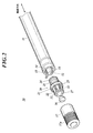
- FIG. 2 is an exploded perspective view of the distal end portion 10a of the probe 10
- FIG. 3 is a cross-sectional view of the distal end portion 10a of the probe 10.
- FIG. 4 is a cross-sectional view showing the surface along IV-IV shown in FIG. 3 as viewed in the direction of the arrow.
- FIG. 5 is a cross-sectional view showing the surface along VV shown in FIG. 3 as viewed in the direction of the arrow.
- the probe 10 includes a flexible tube 11, two measurement optical fibers 12 and 13, a ferrule 14, a plurality of illumination light guides 15,..., A lens 16, and a protective hood 17. And a holder 20 and the like.
- the number of illumination light guides 15 shown is one in order to make the drawing easier to see.
- the base end portion of the flexible tube 11 is attached to the connector 10b.
- the optical fibers for measurement 12, 13 and the light guide for illumination 15,... are passed through the flexible tube 11 from the base end to the distal end of the flexible tube 11, and the optical fibers for measurement 12, 13 and the light guide for illumination 15,.
- the base end is exposed on the surface of the connector 10b.
- optical fibers or optical fiber bundles (a bundle of a plurality of optical fibers), and the illumination light emitted from the illumination light source 6a is guided to the tip side by the illumination light guides 15,.
- the measurement optical fiber 12 guides the excitation light emitted from the excitation light source 6b
- the measurement optical fiber 13 guides the emitted light emitted from the living tissue.
- one optical fiber for measurement may be used both for guiding the excitation light and for guiding the emitted light.
- the number of the optical fibers for measurement 12 is not limited to one and may be a plurality.
- the number of the optical fibers for measurement 13 is not limited to one and may be a plurality.
- the measurement optical fibers 12 and 13 and the illumination light guide 15 extend in the axial direction of the flexible tube 11.
- the illumination light guides 15 are arranged in parallel in the circumferential direction, and the measurement optical fibers 12 and 13 are arranged inside the array of the illumination light guides 15.
- a second flexible tube thinner than the flexible tube 11 is inserted into the flexible tube 11, the measurement optical fibers 12 and 13 are inserted into the second flexible tube, and the illumination light guide 15 is inserted. ,... May be inserted outside the second flexible tube and inside the flexible tube 11.
- the ferrule 14 is shaped like a column.
- the distal ends of the measurement optical fibers 12 and 13 are fixed to the ferrule 14 so as to penetrate the ferrule 14 in the axial direction.
- the optical axes at the distal ends of the measurement optical fibers 12 and 13 are arranged in parallel by the ferrule 14, and the distal surfaces of the measurement optical fibers 12 and 13 and the distal surface of the ferrule 14 are aligned.
- One or both of the measurement optical fibers 12 and 13 are eccentric with respect to the ferrule 14.
- the ferrule 14 is held by the holder 20, and the tip portions of the illumination light guides 15,... Are held by the holder 20.
- the distal ends of the illumination light guides 15 are curved outward in the radial direction of the flexible tube 11 by the holder 20, and the distal ends of the illumination light guides 15,. .
- the material of the holder 20 is a liquid crystal polymer or other resin.
- the holder 20 is preferably black.
- the skeletal shape of the holder 20 when the shape of the holder 20 is grasped roughly is a cylindrical shape. The holder 20 will be described in detail later.
- the protective hood 17 is made of a transparent material and is formed in a cylindrical shape.
- the material of the protective hood 17 is a biocompatible material.
- the protective hood 17 is connected to the distal end of the flexible tube 11 by the holder 20, and the distal end portion of the illumination light guide 15 is inserted into the hollow of the protective hood 17.
- the tip of the illumination light guide 15 is protected by a protective hood 17.
- an unevenness 17 a is formed on a portion near the tip.
- the unevenness 17a is provided on the outer circumferential surface of the protective hood 17 along the circumferential direction between the grooves 17b,... Recessed in the outer circumferential surface of the protective hood 17 along the circumferential direction.
- the plurality of convex portions 17c are provided,. Light emitted from the front end surface of the illumination light guide 15 passes through the protective hood 17 and is diffused by the unevenness 17a. Therefore, the directivity of light emitted from the outer peripheral surface of the protective hood 17 is reduced, and a wide light distribution is obtained.
- the outer peripheral surface of the protective hood 17 may be textured, or a large number of microcavities or fine particles may be dispersed inside the protective hood 17. If it does so, the light radiate
- the protective hood 17 may be configured such that the unevenness, the minute cavities, the fine particles, and the like are not provided in the protective hood 17, and the protective hood 17 allows light to pass through.
- Protective hood 17 also functions as a lens holder. That is, the lens 16 is fitted and fixed inside the protective hood 17, and the optical axis of the lens 16 is arranged so as to be parallel to the axis of the protective hood 17 and the flexible tube 11. Since the lens 16 is disposed inside the protective hood 17, the lens 16 is protected by the protective hood 17.
- the position of the lens 16 is a position between the front end and the base end of the protective hood 17, and the lens 16 is soiled by the protective hood 17. Further, the lens 16 is disposed ahead of the distal end surfaces of the measurement optical fibers 12 and 13, and excitation light emitted from the distal end surface of the measurement optical fiber 12 is projected by the lens 16. Further, the radiated light generated due to the excitation light is projected onto the distal end surface of the measurement optical fiber 13 by the lens 16. The excitation light and radiation light projected by the lens 16 are collected or collimated by the lens 16.
- the holder 20 functions as a holding member that holds the distal ends of the measurement optical fibers 12 and 13 and the illumination light guides 15..., And also functions as a pipe joint that connects the protective hood 17 and the flexible tube 11.
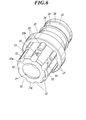
- FIG. 6 is a front perspective view of the holder 20
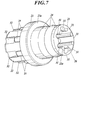
- FIG. 7 is a rear perspective view of the holder 20
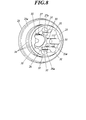
- FIG. 8 is a rear perspective view of the holder 20
- FIG. It is the front perspective view shown by.
- the holder 20 includes a proximal end side fitting portion 21, a distal end side fitting portion 22, a flange 23, a retaining projection 24, ..., a positioning projection 25, ..., a holding hole (first hole) 26, a light passage hole (first passage).
- the rear side of the holder 20 is the proximal end side of the probe 10, and the front side of the holder 20 is the distal end side of the probe 10.
- the distal end side fitting portion 22 is connected to the distal end side of the proximal end side fitting portion 21, and the proximal end side fitting portion 21 and the distal end side fitting portion 22 are integrally formed.
- the proximal end fitting portion 21 and the distal end side fitting portion 22 are formed in a substantially cylindrical shape, and the inside of the proximal end fitting portion 21 and the distal end side fitting portion 22 is hollow.
- the hollow of the base end side fitting part 21 and the front end side fitting part 22 will be described in detail later.
- the proximal end fitting portion 21 is fitted into the distal end side opening of the flexible tube 11, and the distal end side opening of the flexible tube 11 holds the proximal end fitting portion 21. .
- the base end side fitting part 21 and the flexible tube 11 are adhere
- the material of the adhesive that bonds the proximal end fitting portion 21 and the flexible tube 11 is a biocompatible material, and is preferably a waterproof material. Furthermore, in consideration of assemblability, it is preferable to use a thermosetting or photocurable adhesive.
- a plurality of retaining protrusions 24,... are projected on the outer peripheral surface of the proximal end fitting portion 21.
- the retaining protrusions 24,... Extend in the circumferential direction so as to go around the proximal end fitting portion 21 and are arranged in parallel in the axial direction.
- the retaining protrusions 24 are locked to the inner surface of the opening on the distal end side of the flexible tube 11 to prevent the proximal end fitting portion 21 from being detached from the flexible tube 11.
- the retaining protrusions 24 may be screw threads formed in a spiral shape. Further, the number of the retaining protrusions 24 may be single instead of plural.
- the protrusions 24, ... have the same protruding height. Note that any one or more of the retaining protrusions 24,... May have a different protruding height from the other, and the retaining protrusions 24,.
- the flange 23 is provided so as to protrude radially outward from these outer peripheral surfaces at a boundary portion (connecting portion) between the proximal end side fitting portion 21 and the distal end side fitting portion 22.
- the distal end of the flexible tube 11 abuts on the rear surface 23a of the flange 23, and the relative position of the flexible tube 11 and the holder 20 in the axial direction is determined.
- the flange 20 prevents the holder 20 from entering the flexible tube 11 any more.
- the outer peripheral surface of the proximal end fitting portion 21 and the outer peripheral surface of the distal end side fitting portion 22 are the outer peripheral surfaces of the holder 20.
- the distal end fitting portion 22 is fitted into the proximal end opening of the protective hood 17, and the proximal end opening of the protective hood 17 holds the distal end fitting portion 22. Thereby, the front end side fitting part 22 is protected by the protective hood 17.
- the distal end side fitting portion 22 and the protective hood 17 may be bonded, or the distal end side fitting portion 22 and the protective hood 17 may be fixed by a claw or the like.
- the material of the adhesive that bonds the distal end side fitting portion 22 and the protective hood 17 is a biocompatible material, and is preferably a waterproof material. Furthermore, a photocurable or thermosetting adhesive is preferable.
- the proximal end of the protective hood 17 contacts the front surface 23b of the flange 23, and the relative position of the protective hood 17 and the holder 20 in the axial direction is determined.
- the flange 23 prevents the holder 20 from entering the protective hood 17 any more.
- a plurality of positioning protrusions 25 are provided on the outer peripheral surface of the front end side fitting portion 22 so as to protrude.
- the positioning protrusions 25 are fan-shaped columnar protrusions that extend in the axial direction from the front surface 23b of the flange 23 to the front end side. These positioning protrusions 25 are arranged in parallel in the circumferential direction.
- a plurality of recesses 17d,... are formed on the inner surface of the base end side opening of the protective hood 17 (see FIG. 5), and the positioning projections 25,.
- the circumferential position of the protective hood 17 with respect to the distal end side fitting portion 22 is determined, and the relative rotation of the protective hood 17 with respect to the distal end side fitting portion 22 is suppressed.
- the proximal end of the recesses 17d,... Opens at the end face on the proximal end side of the protective hood 17, and when the distal end side fitting portion 22 is inserted into the protective hood 17, the positioning projections 25,. And slides in the axial direction. Since the base end side ends of the recesses 17d are open at the base end side end face of the protective hood 17, the protective hood 17 can be easily formed.
- the number of the positioning protrusions 25 and the recesses 17d may be single instead of plural.
- a plurality of second guide grooves 32 are recessed in the outer peripheral surface of the distal end side fitting portion 22.
- the second guide grooves 32 Extend in the axial direction.
- the second guide grooves 32 are arranged in parallel in the circumferential direction.
- the second guide grooves 32 are in front of the positioning protrusions 25 (see FIG. 3), and the circumferential positions of the second guide grooves 32 are aligned with the circumferential positions of the positioning protrusions 25,. (See FIG. 5).
- the depth of the second guide grooves 32,... Gradually decreases from the proximal end side toward the distal end side, and the bottom of the second guide grooves 32,. Inclined radially outward with respect to the direction.
- the ends on the distal end side of the second guide grooves 32,... are open at the distal end side end surface 22a of the distal end side fitting portion 22 (hereinafter referred to as the front end surface 22a).
- the hollow of the base end side fitting part 21 and the front end side fitting part 22 is demonstrated in detail. As shown in FIGS. 6 to 9, the hollows of the proximal end side fitting portion 21 and the distal end side fitting portion 22 include a holding hole 26, a light passage hole 27, and first guide grooves 31,.
- the holding hole 26 is drilled along the axial direction from an end surface 21a (hereinafter referred to as a rear end surface 21a) on the proximal end side of the proximal end fitting portion 21 along the axial direction, and the light passage hole 27 is formed on the distal end fitting portion 22.
- the holding hole 26 and the light passage hole 27 are formed between the rear end face 21a of the base end side fitting portion 21 and the front end face 22a of the front end side fitting portion 22 from the front end face 22a to the base end side along the axial direction. It communicates between them.
- the first guide grooves 31 are recessed on the inner surface of the holding hole 26.
- the holding hole 26, and the light passage hole 27 constitute a hollow of the proximal end side fitting portion 21 and the distal end side fitting portion 22.
- the light passage hole 27 has a conical frustum (for example, a truncated cone). That is, the diameter of the light passage hole 27 gradually increases from the proximal end side toward the distal end side.
- the shape of the light passage hole 27 may be a columnar shape (for example, a columnar shape) whose center line is the axial direction.
- the light passage hole 27 and the holding hole 26 are concentric.
- the minimum diameter of the rear portion of the light passage hole 27 is smaller than the diameter of the holding hole 26, and a step portion 26 a is formed between the inner surface of the light passage hole 27 and the inner surface of the holding hole 26.
- the step portion 26 a serves as an abutting portion of the holding hole 26.
- the inner surface of the light passage hole 27 and the inner surface of the holding hole 26 are the inner peripheral surface of the holder 20.
- the position in the axial direction of the boundary between the holding hole 26 and the light passage hole 27 is in the middle along the front-rear direction of the distal end side fitting portion 22.
- the axial position of the boundary between the holding hole 26 and the light passage hole 27 is between the rear end surface 21a of the base end side fitting portion 21 and the front end surface 22a of the front end side fitting portion 22 at any position. Good.
- the holding hole 26 holds the ferrule 14, and the ferrule 14 is fitted in the holding hole 26.
- the ferrule 14 is held in the holding hole 26, and the tip surfaces of the measurement optical fibers 12 and 13 are opposed to the lens 16 through the light passage hole 27.
- the light passage hole 27 is formed into a conical frustum (for example, a truncated cone), excitation light emitted from the distal end surface of the measurement optical fiber 12 or radiation incident on the distal end surface of the measurement optical fiber 13.
- the luminous flux of light is not limited, and the optical path of excitation light and radiant light is not disturbed.
- One or both of the measurement optical fibers 12 and 13 are eccentric with respect to the holding hole 26.
- the peripheral edge portion of the front end surface of the ferrule 14 abuts on the step portion 26a so that the ferrule 14 cannot be inserted any more.
- the ferrule 14 is preferably fixed to the holding hole 26 with an adhesive or the like.
- a recess 27 a is formed in a portion near the base end of the inner surface of the light passage hole 27. As shown in FIGS. 3 and 5, the circumferential position of the recess 27 a on the inner surface of the light passage hole 27 is the side where the measurement optical fibers 12 and 13 are eccentric with respect to the center line of the ferrule 14. By forming the depression 27a, vignetting of excitation light emitted from the distal end surface of the measurement optical fiber 12 and vignetting of incident light incident on the distal end surface of the measurement optical fiber 13 are prevented.
- the first guide grooves 31,... Extend in the axial direction from the rear opening of the holding hole 26 to the abutting portion (stepped portion 26a), and the rear ends of the first guide grooves 31,. Is open on the rear end surface 21a of the base end side fitting portion 21.
- the first guide grooves 31 are parallel to each other and are arranged in parallel in the circumferential direction.
- the first guide grooves 31, ... are closer to the base end than the second guide grooves 32, ..., and the circumferential positions of the first guide grooves 31, ... are aligned with the circumferential positions of the second guide grooves 32, ....
- Communication holes 33 are formed at the tip side end portions of the first guide grooves 31.
- the communication holes 33,... Penetrate from the distal end side end of the first guide groove 31,... To the proximal end side end to the second guide groove 32, and the first guide groove 31,. It communicates with the communication holes 33.
- the first guide groove 31, the communication hole 33, and the second guide groove 32 are continuously connected from the rear end surface 21 a of the base end side fitting portion 21 to the front end surface 22 a of the distal end side fitting portion 22.
- a passage formed by the first guide groove 31, the communication hole 33, and the second guide groove 32 is a guide path 30 that guides the illumination light guide 15.
- the number of guide paths 30 is plural, but may be single. In that case, the number of illumination light guides 15 is also singular.
- the front end portion of the illumination light guide 15 is inserted into the first guide groove 31, the communication hole 33, and the second guide groove 32, and the first guide groove 31 and the second guide groove.
- the bottom of the groove 32 is laid. Since the bottom of the second guide groove 32 is inclined with respect to the axial direction, the portion near the tip of the guide path 30 (the portion corresponding to the second guide groove 32) is curved outward in the radial direction, and the illumination light guide The tip of 15 is also curved outward in the radial direction. 10, the depth of the first guide groove 31,... Near the tip 31a gradually increases toward the tip, and the bottom of the first guide groove 31,. By tilting radially outward with respect to the axial direction, the distal end portion of the illumination light guide 15 may be bent radially outward by the distal end portion 31 a of the first guide groove 31.
- the tip end of the second guide groove 32 is open, and the tip of the illumination light guide 15 extends from the second guide groove 32 in the extending direction of the second guide groove 32. Yes. Even if the distal end portion of the illumination light guide 15 protrudes from the front end surface 22 a or the outer peripheral surface of the distal end side fitting portion 22, the protruding portion is a recess 17 d formed on the inner surface of the proximal end opening of the protective hood 17. Get in. That is, when the distal end side fitting portion 22 is inserted into the protective hood 17, the distal end portion of the illumination light guide 15 is guided by the concave portion 17d.
- the positioning protrusion 25 is inserted into the concave portion 17d, so that water-stopping and airtightness are maintained. Thereby, the front-end
- the guide path 30 for guiding the illumination light guide 15 is not a through-hole penetrating from the rear end surface 21a of the proximal end side fitting portion 21 to the front end surface 22a of the distal end side fitting portion 22. That is, as shown in FIG. 4, a part of the first guide groove 31 of the guide path 30 is recessed so as to cut out the inner surface of the holding hole 26. The portion is opened at the inner surface of the holding hole 26, and as shown in FIG. 5, a part of the second guide groove 32 of the guide path 30 is recessed so as to cut out the outer peripheral surface of the distal end side fitting portion 22. In the guide path 30, the second guide groove 32 is open on the outer peripheral surface of the distal end side fitting portion 22.
- the base end side fitting part 21 and the front end side fitting part 22 can be made thin, and the base end side fitting part 21 and the front end side fitting part 22 can be made into a small diameter. Therefore, the tip portion of the probe 10 can be reduced in size. Moreover, the material cost of the holder 20 can also be reduced.
- the circumferential position of the first guide groove 31 and the circumferential position of the second guide groove 32 are aligned, and the radial position of the distal end side end portion of the first guide groove 31 and the proximal end of the second guide groove 32 Since the radial positions of the side ends are aligned, the distal end of the illumination light guide 15 is inserted into the proximal end of the first guide groove 31 by inserting the distal end of the illumination light guide 15 into the first end.
- the first guide groove 31, the communication hole 33, and the second guide groove 32 can be attached. Further, when the illumination light guide 15 is inserted, the tip of the illumination light guide 15 can be bent by the bottom of the second guide groove 32. Therefore, installation of the illumination light guide 15 is easy.
- the cross-sectional shape of the first guide grooves 31,... is fan-shaped, the radius of the first guide grooves 31,... Is slightly larger than the radius of the illumination light guides 15,.
- the front ends of the guides 15 are inserted into the first guide grooves 31 with play. Note that the radius of the first guide grooves 31 may be equal to the radius of the illumination light guide 15.
- the illumination light guides 15,... are moved from the first guide grooves 31,. It is designed not to come out.
- the central angle of the sectional fan shape of the first guide grooves 31,... Is larger than 180 degrees, and the opening width of the first guide grooves 31, ... (the first guide grooves 31,. ) Is shorter than the diameter of the illumination light guide 15, the illumination light guides 15,... Are clamped in the first guide grooves 31, and the illumination light guides 15,.
- the retaining hole 26 is prevented from coming off from.
- the central angle of the sectional fan shape of the first guide grooves 31,... Is smaller than 180 degrees, and the opening width of the first guide grooves 31,.
- the width of the first guide groove 31 may be longer than the diameter of the illumination light guide 15.
- the cross-sectional shape of the second guide grooves 32,... is fan-shaped, the radius of the second guide grooves 32,... Is larger than the radius of the illumination light guides 15,. ,... Are inserted into the second guide grooves 32 with play.
- the radius of the second guide grooves 32,... May be equal to the radius of the illumination light guide 15.
- the tips of the illumination light guides 15,... are supported on the inner surface of the protective hood 17 (specifically, the recesses 17 d shown in FIGS. 3 and 5).
- the light guides 15 are prevented from coming out of the second guide grooves 32.
- the radius of the second guide grooves 32,... Is substantially equal to the radius of the illumination light guides 15, ..., and the opening width of the second guide grooves 32,.
- the width of the second guide grooves 32 along the circumferential direction of the outer peripheral surface may be shorter than the diameter of the illumination light guide 15. Then, the illumination light guides 15 are clamped in the second guide grooves 32, and the illumination light guides 15 are reliably prevented from falling off.
- the cross-sectional shape of the first guide grooves 31,... has been described, but the cross-sectional shape of the first guide grooves 31,.
- the first guide groove 31 may be a V-shaped groove or a rectangular groove. The same applies to the cross-sectional shape of the second guide groove 32.
- the communication hole 33 is a circular hole.
- the radius of the communication hole 33 is equal to the radius of the illumination light guide 15 or slightly larger than the radius of the illumination light guide 15.
- the tip of the illumination light guide 15 is inserted into the communication hole 33, and the outer peripheral surface of the illumination light guide 15 is surrounded by the inner surface of the communication hole 33. Therefore, the illumination light guide 15 is prevented from falling off the guide path 30.
- the shape of the communication hole 33 is not circular, but may be a triangle, a quadrilateral or other polygons, or may be an ellipse.
- Embodiments to which the present invention can be applied are not limited to the above-described embodiments, and can be appropriately changed without departing from the spirit of the present invention. Several modifications will be described below. In the description of the modified example, a part changed from the configuration described with reference to FIGS. 2 to 12 will be mainly described. Further, in the description of the modified example, the same reference numerals are given to the portions corresponding to the configurations described with reference to FIGS.
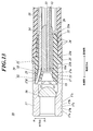
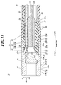
- FIG. 13 is a modification of the communication hole 33 shown in FIG. 10
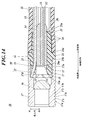
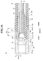
- FIG. 14 is a modification of the communication hole 33 shown in FIG.
- the communication hole 33 shown in FIGS. 13 and 14 is longer than the communication hole 33 shown in FIGS. 3 and 10. That is, as shown in FIGS. 3 and 10, the end portion on the distal end side of the first guide groove 31 and the end portion on the proximal end side of the second guide groove 32 have substantially the same axial position, and the communication hole 33. Is short.
- the end portion on the distal end side of the first guide groove 31 is separated from the end portion on the proximal end side of the second guide groove 32 toward the proximal end side. Is elongated from the end on the distal end side of the first guide groove 31 to the end on the proximal end side of the second guide groove 32.
- the communication hole 33 is not parallel to the axial direction. That is, the communication hole 33 is inclined radially outward with respect to the axial direction. Therefore, the distal end portion of the illumination light guide 15 is curved outward in the radial direction.
- the end portion on the distal end side of the first guide groove 31 is separated from the end portion on the proximal end side of the second guide groove 32 toward the proximal end side, and the communication hole 33 is formed on the first guide groove 31. It is perforated from the end on the distal end side to the end on the proximal end side of the second guide groove 32 and is elongated. Accordingly, the communication hole 33 shown in FIG. 15 is longer than the communication hole 33 shown in FIGS.
- the communication hole 33 is curved. That is, the portion 33a near the base end of the communication hole 33 is parallel to the axial direction, and the remaining portion 33b near the leading end is inclined radially outward with respect to the axial direction. Therefore, the distal end portion of the illumination light guide 15 is curved radially outward by the communication hole 33.
- the end portion on the distal end side of the first guide groove 31 is separated from the end portion on the proximal end side of the second guide groove 32 toward the proximal end side, and the communication hole 33 is formed in FIGS.
- the communication holes 33 are opened obliquely. Since the communication hole 33 is greatly opened obliquely, the tip of the illumination light guide 15 is inserted into the communication hole 33 with play.
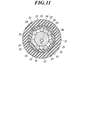
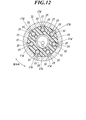
- the cross-sectional shape of the first guide groove 31 is as shown in FIG. 4 or FIG. 11, and the cross-sectional shape of the second guide groove 32 is as shown in FIG. 5 or FIG. It is.
- the flange is omitted, and the proximal end of the protective hood 17 is abutted against the distal end of the flexible tube 11.
- the flexible tube 11 may include a portion on the proximal end side of the protective hood 17.
- the entire guide path 30 is opened on the outer peripheral surfaces of the proximal end side fitting portion 21 and the distal end side fitting portion 22. That is, the guide path 30 includes a guide groove 34, and the guide groove 34 is recessed on the outer peripheral surfaces of the proximal end side fitting portion 21 and the distal end side fitting portion 22.
- the guide groove 34 extends along the axial direction from the rear end surface 21a of the base end side fitting portion 21 to the front end surface 22a of the front end side fitting portion 22, and the base end side end portion of the guide groove 34 is the base end side fitting.
- An opening is formed at the rear end surface 21 a of the joint portion 21, and a front end side end portion of the guide groove 34 is opened at a front end surface 22 a of the front end side fitting portion 22. Further, the positioning protrusion 25 is divided by the guide groove 34.
- the front end of the illumination light guide 15 is inserted into the guide groove 34 and laid on the bottom of the guide groove 34.
- the depth of the portion 34a near the tip of the guide groove 34 gradually decreases toward the tip, and the bottom of the portion 34a near the tip of the guide groove 34 is inclined radially outward with respect to the axial direction.
- the depth of the remaining proximal end portion 34b of the guide groove 34 is uniform, and the bottom of the portion 34b is parallel to the axial direction. Therefore, the distal end portion of the illumination light guide 15 is curved outward in the radial direction.
- the guide path 30 is the guide groove 34 formed in the outer peripheral surface of the base end side fitting part 21 and the front end side fitting part 22, the base end side fitting part 21 and the front end side fitting part 22 are made thin. be able to. Therefore, the proximal end fitting portion 21 and the distal end fitting portion 22 can be reduced in diameter, and the distal end portion of the probe 10 can be reduced in size.
- the cross-sectional shape of the guide groove 34 is the same as the cross-sectional shape of the first guide groove 31 shown in FIG.
- the entire guide path 30 is opened on the inner surfaces of the holding hole 26 and the light passage hole 27. That is, the guide path 30 includes a guide groove 35, and the guide groove 35 is recessed on the inner surfaces of the holding hole 26 and the light passage hole 27.
- the guide groove 35 extends along the axial direction from the rear end surface 21a of the proximal end side fitting portion 21 to the front end surface 22a of the distal end side fitting portion 22, and the proximal end portion of the guide groove 35 is fitted to the proximal end side.
- An opening is formed at the rear end surface 21 a of the joint portion 21, and a front end side end portion of the guide groove 35 is opened at a front end surface 22 a of the front end side fitting portion 22.
- the front end of the illumination light guide 15 is inserted into the guide groove 35 and laid on the bottom of the guide groove 35.
- the bottom of the portion 35a near the tip of the guide groove 35 is inclined radially outward with respect to the axial direction.
- the bottom of the remaining proximal end portion 35b of the guide groove 35 is parallel to the axial direction. Therefore, the distal end portion of the illumination light guide 15 is curved outward in the radial direction.
- the proximal end fitting portion 21 and the distal end fitting portion 22 can be made thin. Therefore, it is possible to reduce the diameter of the proximal end fitting portion 21 and the distal end side fitting portion 22 and the size of the distal end portion of the probe 10.
- the cross-sectional shape of the front end portion 35a of the guide groove 35 is the same as the cross-sectional shape of the second guide groove 32 shown in FIG. Therefore, the illumination light guide 15 is clamped to the tip portion 35 a of the guide groove 35, and the illumination light guide 15 does not come out of the tip portion 35 a of the guide groove 35.
- the cross-sectional shape of the remaining proximal end portion 35b of the guide groove 35 is the same as the cross-sectional shape of the second guide groove 32 shown in FIG.
- the guide path 30 includes a guide hole 36 and a guide groove 37.
- the guide groove 37 is provided in the same manner as the second guide groove 32.
- the guide hole 36 is pierced along the axial direction from the rear end surface 21 a of the base end side fitting portion 21 around the holding hole 26, and penetrates to the end portion of the guide groove 37 on the base end side.
- the front end of the illumination light guide 15 is inserted into the guide hole 36 and the guide groove 37, and is laid on the bottom of the guide groove 37. Therefore, the distal end portion of the illumination light guide 15 is curved outward in the radial direction.
- the tip-side fitting portion 22 can be made thin. Therefore, the diameter of the distal end side fitting portion 22 and the size of the distal end portion of the probe 10 can be reduced.
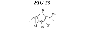
- an abutting portion (stopper) 28 protrudes from the end of the second guide groove 32 on the tip side.
- the distal end portion of the illumination light guide 15 When the distal end portion of the illumination light guide 15 is inserted into the first guide groove 31, the communication hole 33, and the second guide groove 32, the distal end surface of the illumination light guide 15 hits the abutting portion 28, and the illumination light guide 15 is positioned. It can be performed.
- the height of the abutting portion 28 is not high enough to cover the front end surface of the lighting light guide 15, but only a part (peripheral portion) of the front end surface of the lighting light guide 15 hits the abutting portion 28.
- the abutting portion 28 is set so that the end face of the clad of the optical fiber hits the abutting portion 28 and the end face of the core does not hit the abutting portion 28. It is preferable.
- the shape of the abutting portion 28 is as shown in FIGS. 21 to 23, for example.
- the abutting portion 28 may be installed not only at the front end side end portion of the guide path 30 shown in FIG. 3 but also at the front end side end portion of the guide path 30 shown in FIGS. 10 and 13 to 19.
- the abutment portion 28 is projected from the end of the second guide groove 32 on the tip side.
- the abutment portion 28 is projected from the end of the guide groove 34 on the front end side.
- the abutting portion 28 protrudes from the end of the guide groove 35 on the tip side.
- the abutting portion 28 protrudes from the end of the guide groove 37 on the tip side.
- FIG. 24 shows the tip of the video scope 10A.
- the probe 10 shown in FIG. 3 is changed to a video scope 10A, and the illumination light guide holding structure according to the present invention is applied to the video scope 10A. That is, the image sensor fixing rod 52 is fitted into the holding hole 26 instead of the ferrule 14, and the holding hole 26 holds the image sensor fixing rod 52.
- a solid-state image sensor 51 is attached to the distal end surface of the image sensor fixing rod 52, and the solid-state image sensor 51 faces the lens 16.
- the transmission cable 53 is passed through the flexible tube 11 instead of the measurement optical fibers 12 and 13, and the distal end portion of the transmission cable 53 passes through the image sensor fixing rod 52 in the axial direction and is fixed to the image sensor fixing rod 52.
- the tip of the transmission cable 53 is connected to the solid-state image sensor 51.
- the lens 16 forms an image ahead of the protective hood 17 on the solid-state image sensor 51.
- the image is captured by the solid-state image sensor 51 and converted to a video signal, and the video signal of the image is transmitted by the transmission cable 53.
- the base unit 6 (see FIG. 1) is provided with an image processing circuit instead of the excitation light source 6b and the spectroscope 6c, and the video signal is signal-processed by the image processing circuit.
- the number of lenses 16 may be one or plural.
- probe 10 shown in FIGS. 10 and 13 to 20 may be changed to the video scope 10A as in the case shown in FIG.
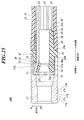
- FIG. 25 shows the distal end portion of the catheter 10B.
- the probe 10 shown in FIG. 3 is changed to a catheter 10B, and the illumination light guide holding structure according to the present invention is applied to the catheter 10B. That is, the lens 16, the optical fibers for measurement 12, 13 and the ferrule 14 are not provided.
- the proximal end portion of the flexible tube 11 is bifurcated, and a connector 10b (see FIG. 1) is attached to one of the branched branches, and the connector 10b is connected to the base unit 6 to provide a light source for illumination.
- the illumination light emitted from 6a is guided by the illumination light guide 15.
- one of the branched branches is open, and a treatment instrument (for example, forceps) can be inserted into the opening, and the distal end of the treatment instrument can be projected forward from the distal opening of the protective hood 17. Therefore, the holes 26 and 27 are treatment instrument through holes.
- a treatment instrument for example, forceps
- the treatment instrument is passed through the second flexible tube.
- probe 10 shown in FIGS. 10 and 13 to 20 may also be changed to the catheter 10B as in the case shown in FIG.
- the present invention can be used for a device for illuminating a lumen, such as a probe, a video scope, and a catheter.
Landscapes
- Physics & Mathematics (AREA)
- Optics & Photonics (AREA)
- Life Sciences & Earth Sciences (AREA)
- General Physics & Mathematics (AREA)
- Health & Medical Sciences (AREA)
- Surgery (AREA)
- Astronomy & Astrophysics (AREA)
- Medical Informatics (AREA)
- General Health & Medical Sciences (AREA)
- Radiology & Medical Imaging (AREA)
- Nuclear Medicine, Radiotherapy & Molecular Imaging (AREA)
- Engineering & Computer Science (AREA)
- Biomedical Technology (AREA)
- Pathology (AREA)
- Molecular Biology (AREA)
- Heart & Thoracic Surgery (AREA)
- Animal Behavior & Ethology (AREA)
- Biophysics (AREA)
- Public Health (AREA)
- Veterinary Medicine (AREA)
- Endoscopes (AREA)
- Instruments For Viewing The Inside Of Hollow Bodies (AREA)
Abstract
筒状のホルダー(20)は、可撓性チューブ(11)の先端側開口及び筒状の保護フード(17)の基端側開口に嵌め込まれて、可撓性チューブ(11)と保護フード(17)を連結する。ホルダー(20)に設けられた案内路(30)がホルダー(20)の基端側端面(21a)から先端側端面(22a)まで通じ、案内路(30)の少なくとも一部がホルダー(20)の外周面又は内周面において開放され、案内路(30)の先端寄り部分が径方向外方へ湾曲し、照明用ライトガイド(15)の先端部が案内路(30)に挿入されている。
Description
本発明は、体腔に挿入されるプローブ、ビデオスコープ又はカテーテル等に用いられる照明用ライトガイド保持構造及びホルダーに関する。
生体組織の病変状態を観察するために、様々な技術が提案され、実用化されている。特に、内視鏡は、広く普及している(例えば、特許文献1参照)。内視鏡が管腔へ挿入されて、管腔壁の生体組織が内視鏡の先端部から出射した照明光によって照明され、管腔壁の生体組織が内視鏡の先端部で撮影される。内視鏡によって撮影された像は、表示装置及び印刷装置等の出力装置に伝送されて、出力装置から出力される。また、内視鏡の照明として、ライトガイド(例えば、特許文献2参照)が用いられることがある。
内視鏡を用いた画像診断だけでなく、蛍光を用いて診断を行う技術が提案されている。蛍光を用いて診断を行うためには、生体組織の測定部位から蛍光が発するようにその測定部位に励起光(例えば、紫外線)を照射し、発生した蛍光の波長や強度を分析する。そのような診断を行うべく、ケーブル状のプローブが開発されており、生体組織の変性や癌等の疾患状態(例えば、疾患の種類や浸潤範囲)の診断に用いられている。
この種のプローブには、投光用光ファイバー、受光用光ファイバー及びレンズ等が内蔵されている。投光用光ファイバーの先端から出射した励起光がレンズによって生体組織の測定部位に投射され、生体組織の測定部位から発した蛍光がそのレンズによって受光用光ファイバーの先端に投射される。受光用光ファイバーに入射した蛍光は受光用光ファイバーによってスペクトル解析装置に伝送され、蛍光のスペクトル解析がその装置によって行われる。
また、照明用ライトガイドが内蔵されたプローブもあり、照明用ライトガイドによって導光された照明光がプローブの先端部から照射される。そのため、プローブの先端部の周囲が照明される。
プローブ及び内視鏡の何れにおいても、先端部の周囲の照明範囲が広いことが望ましい。例えば、特許文献1に記載の内視鏡では、照明用ライトガイドの先端部が内視鏡の軸線方向から径方向外方に湾曲されていることで、照明範囲が広くなっている。
一般的に、照明用ライトガイドの先端部を内視鏡やプローブの先端部の内部に固定するべく、ホルダーが用いられる。具体的には、照明用ライトガイドの先端部がホルダーを軸線方向に貫通することによって、照明用ライトガイドの先端部がホルダーによって抱持され、そのホルダーが内視鏡やプローブの先端部の内部に固定される。
ところが、照明用ライトガイドの先端部をホルダーによって固定した場合、照明用ライトガイドの先端部を特許文献1に記載のように径方向外方に湾曲させると、照明用ライトガイドが通される貫通孔も径方向外方に湾曲される。そのため、ホルダーの径に対して貫通孔の占める範囲が大きくなってしまう。そうすると、ホルダーの肉厚が大きくなってしまうとともに、ホルダーの径も大きくなってしまう。
そこで、本発明が解決しようとする課題は、照明用ライトガイドを固定するホルダーを薄肉にして、ホルダーを小径化できるようにすることである。
以上の課題を解決するための請求項1に係る発明は、チューブの先端側開口及び筒状の保護フードの基端側開口に嵌め込まれて、前記チューブと前記保護フードを連結する筒状のホルダーに、前記チューブに挿入された照明用ライトガイドの先端部を保持する照明用ライトガイド保持構造において、前記ホルダーに設けられた案内路が前記ホルダーの基端側端面から前記ホルダーの先端側端面まで通じ、前記案内路の少なくとも一部が前記ホルダーの外周面又は内周面において開放され、前記案内路の先端寄り部分が径方向外方へ湾曲し、前記照明用ライトガイドの先端部が前記案内路に挿入されていることを特徴とする照明用ライトガイド保持構造である。
請求項2に係る発明は、前記案内路が、前記ホルダーの内周面の基端寄り部分に凹設され、軸線方向に延在した第一案内溝と、前記第一案内溝よりも先端寄りにおいて前記ホルダーの外周面に凹設され、軸線方向に延在した第二案内溝と、前記第一案内溝の先端側端部から前記第二案内溝の基端側端部まで貫通した連通穴と、を有し、前記第二案内溝の底が軸線方向から径方向外方へ傾斜し、前記照明用ライトガイドの先端部が前記第一案内溝、前記連通穴及び前記第二案内溝に挿入されていることを特徴とする請求項1に記載の照明用ライトガイド保持構造である。
請求項3に係る発明は、前記案内路が、前記ホルダーの外周面に凹設され、前記ホルダーの基端側の端面から前記ホルダーの先端側の端面まで軸線方向に沿って延在した案内溝を有し、前記案内溝の底のうち基端寄り部分が軸線方向に対して平行であり、前記案内溝の底のうち先端寄り部分が軸線方向から径方向外方へ傾斜し、前記照明用ライトガイドの先端部が前記案内溝に挿入されていることを特徴とする請求項1に記載の照明用ライトガイド保持構造である。
請求項4に係る発明は、前記案内路が、前記ホルダーの内周面に凹設され、前記ホルダーの基端側の端面から前記ホルダーの先端側の端面まで軸線方向に沿って延在した案内溝を有し、前記案内溝の底のうち基端寄り部分が軸線方向に対して平行であり、前記案内溝の底のうち先端寄り部分が軸線方向から径方向外方へ傾斜し、前記照明用ライトガイドの先端部が前記案内溝に挿入されていることを特徴とする請求項1に記載の照明用ライトガイド保持構造である。
請求項5に係る発明は、前記案内路が、前記ホルダーの外周面の基端寄り部分に凹設され、軸線方向に延在した案内溝と、前記ホルダーの基端側の端面から先端側へ軸線方向に沿って穿孔され、前記案内溝の基端側端部に通じた案内孔と、を有し、前記案内溝の底が軸線方向から径方向外方へ傾斜し、前記照明用ライトガイドの先端部が前記案内孔及び前記案内溝に挿入されていることを特徴とする請求項1に記載の照明用ライトガイド保持構造である。
請求項6に係る発明は、チューブの先端側開口及び筒状の保護フードの基端側開口に嵌め込まれて、前記チューブと前記保護フードを連結する筒状のホルダーにおいて、前記チューブの先端側開口に嵌め込まれる基端側嵌合部と、前記基端側嵌合部の先端側に連結され、前記保護フードの基端側開口に嵌め込まれる先端側嵌合部と、前記基端側嵌合部の基端側端面から先端側へ軸線方向に沿って穿孔された第一の孔と、前記先端側嵌合部の先端側端面から基端側へ軸線方向に沿って穿孔され、前記第一の孔に通じた第二の孔と、前記基端側嵌合部及び前記先端側嵌合部に設けられ、前記基端側嵌合部の基端側端面から前記先端側嵌合部の先端側端面まで通じた案内路と、を備え、前記案内路の少なくとも一部が前記第一の孔の内面、前記第二の孔の内面、前記基端側嵌合部の外周面又は前記先端側嵌合部の外周面において開放され、前記案内路の先端寄り部分が径方向外方へ湾曲し、前記照明用ライトガイドの先端部が前記案内路に挿入されていることを特徴とするホルダーである。
請求項7に係る発明は、前記案内路が、前記第一の孔の内面に凹設され、軸線方向に延在した第一案内溝と、前記第一案内溝よりも先端寄りにおいて前記先端側嵌合部の外周面に凹設され、軸線方向に延在した第二案内溝と、前記第一案内溝の先端側端部から前記第二案内溝の基端側端部まで貫通した連通穴と、を有し、前記第二案内溝の底が軸線方向から径方向外方へ傾斜し、前記照明用ライトガイドの先端部が前記第一案内溝、前記連通穴及び前記第二案内溝に挿入されていることを特徴とする請求項6に記載のホルダーである。
請求項8に係る発明は、前記案内路が、前記基端側嵌合部及び前記先端側嵌合部の外周面に凹設され、前記基端側嵌合部の基端側の端面から前記先端側嵌合部の先端側の端面まで軸線方向に沿って延在した案内溝を有し、前記案内溝の底のうち基端寄り部分が軸線方向に対して平行であり、前記案内溝の底のうち先端寄り部分が軸線方向から径方向外方へ傾斜し、前記照明用ライトガイドの先端部が前記案内溝に挿入されていることを特徴とする請求項6に記載のホルダーである。
請求項9に係る発明は、前記案内路が、前記第一の孔及び前記第二の孔の内面に凹設され、前記基端側嵌合部の基端側の端面から前記先端側嵌合部の先端側の端面まで軸線方向に沿って延在した案内溝を有し、前記案内溝の底のうち基端寄り部分が軸線方向に対して平行であり、前記案内溝の底のうち先端寄り部分が軸線方向から径方向外方へ傾斜し、前記照明用ライトガイドの先端部が前記案内溝に挿入されていることを特徴とする請求項6に記載のホルダーである。
請求項10に係る発明は、前記案内路が、前記先端側嵌合部の外周面に凹設され、軸線方向に延在した案内溝と、前記第一の孔の周囲において前記基端側嵌合部の端面から先端側へ軸線方向に沿って穿孔され、前記案内溝の基端側端部に通じた案内孔と、を有し、前記案内溝の底が軸線方向から径方向外方へ傾斜し、前記照明用ライトガイドの先端部が前記案内孔及び前記案内溝に挿入されていることを特徴とする請求項6に記載のホルダーである。
請求項11に係る発明は、前記第二の孔は先端側に向かって径が漸増するよう錐台に形成されている請求項6から10の何れか一項に記載のホルダーである。
請求項12に係る発明は、その先端部から励起光を生体組織に投光するとともに、その励起光に起因して前記生体組織から生じた放射光をその先端部で受光するプローブの前記先端部に設けられ、前記プローブの先端側となる筒状の保護フードと前記プローブの基端側となるチューブとを連結するホルダーにおいて、前記チューブの先端側開口に嵌め込まれる基端側嵌合部と、前記基端側嵌合部の先端側に連結され、前記保護フードの基端側開口に嵌め込まれる先端側嵌合部と、前記基端側嵌合部の基端側端面から先端側へ軸線方向に沿って穿孔され、励起光又は放射光の導光をする測定用光ファイバーが固定されたフェルールをくわえ込む保持孔と、前記先端側嵌合部の先端側端面から基端側へ軸線方向に沿って穿孔され、前記保持孔に通じた光通過孔と、前記基端側嵌合部及び前記先端側嵌合部に周方向に並設され、前記チューブに挿入された複数の照明用ライトガイドの先端部がそれぞれ挿入される複数の案内路と、を備えることを特徴とするホルダーである。
請求項13に係る発明は、前記基端側嵌合部と前記先端側嵌合部との連結部の外周面に径方向外方へ出っ張るように設けられ、前記保護フードと前記チューブの間に挟まれるフランジを更に備えることを特徴とする請求項12に記載のホルダーである。
請求項14に係る発明は、前記フランジよりも先端寄りにおいて前記先端側嵌合部の外周面に凸設された位置決め突起を更に備え、前記位置決め突起が前記保護フードの内面に形成された凹部に嵌合することを特徴とする請求項13に記載のホルダーである。
請求項15に係る発明は、前記光通過孔は先端側に向かって径が漸増するよう錐台に形成されていることを特徴とする請求項12から14の何れか一項に記載のホルダーである。
請求項16に係る発明は、前記光通過孔の内面の基端寄り部分に窪みが形成されている請求項12から15の何れか一項に記載のホルダーである。
請求項17に係る発明は、前記測定用光ファイバーが前記フェルールに対して偏心しており、前記光通過孔の内面における前記窪みの周方向の位置が前記測定用光ファイバーの偏心側であることを特徴とする請求項16に記載のホルダーである。
請求項18に係る発明は、前記基端側嵌合部の外周面に凸設された一又は複数の抜け止め突起を更に備えることを特徴とする請求項12から17の何れか一項に記載のホルダーである。
請求項19に係る発明は、前記抜け止め突起の数が複数であり、前記抜け止め突起が前記基端側嵌合部を周回するように周方向に延在しているとともに、軸線方向に並列されていることを特徴とする請求項18に記載のホルダーである。
請求項20に係る発明は、前記抜け止め突起の数が複数であり、前記抜け止め突起は突出高さが互いに異なることを特徴とする請求項18に記載のホルダーである。
請求項21に係る発明は、前記案内路が前記基端側嵌合部の基端側端面から前記先端側嵌合部の先端側端面まで通じている請求項12から20の何れか一項に記載のホルダーである。
請求項22に係る発明は、前記案内路の先端寄り部分が径方向外方へ曲がり、前記案内路の少なくとも一部が前記保持孔の内面、前記光通過孔の内面、前記基端側嵌合部の外周面又は前記先端側嵌合部の外周面において開放されていることを特徴とする請求項21に記載のホルダーである。
請求項23に係る発明は、前記案内路が、前記保持孔の内面に凹設され、軸線方向に延在した第一案内溝と、前記第一案内溝よりも先端寄りにおいて前記先端側嵌合部の外周面に凹設され、軸線方向に延在した第二案内溝と、前記第一案内溝の先端側端部から前記第二案内溝の基端側端部まで貫通した連通穴と、を有し、前記第二案内溝の底が軸線方向から径方向外方へ傾斜し、前記照明用ライトガイドの先端部が前記第一案内溝、前記連通穴及び前記第二案内溝に挿入されていることを特徴とする請求項22に記載のホルダーである。
請求項24に係る発明は、前記案内路の先端寄り部分が径方向外方へ曲がり、前記案内路の少なくとも一部が前記保持孔の内面、前記光通過孔の内面、前記基端側嵌合部の外周面又は前記先端側嵌合部の外周面において開放され、前記案内路が、前記基端側嵌合部及び前記先端側嵌合部の外周面に凹設され、前記基端側嵌合部の基端側の端面から前記先端側嵌合部の先端側の端面まで軸線方向に沿って延在した案内溝を有し、前記案内溝の底のうち基端寄り部分が軸線方向に対して平行であり、前記案内溝の底のうち先端寄り部分が軸線方向から径方向外方へ傾斜し、前記照明用ライトガイドの先端部が前記案内溝に挿入されていることを特徴とする請求項12に記載のホルダーである。
請求項25に係る発明は、前記案内路が、前記保持孔及び前記光通過孔の内周面に凹設され、前記基端側嵌合部の基端側の端面から前記先端側嵌合部の先端側の端面まで軸線方向に沿って延在した案内溝を有し、前記案内溝の底のうち基端寄り部分が軸線方向に対して平行であり、前記案内溝の底のうち先端寄り部分が軸線方向から径方向外方へ傾斜し、前記照明用ライトガイドの先端部が前記案内溝に挿入されていることを特徴とする請求項22に記載のホルダーである。
請求項26に係る発明は、前記案内路が、前記先端側嵌合部の外周面に凹設され、軸線方向に延在した案内溝と、前記保持孔の周囲において前記基端側嵌合部の端面から先端側へ軸線方向に沿って穿孔され、前記案内溝の基端側端部に通じた案内孔と、を有し、前記案内溝の底が軸線方向から径方向外方へ傾斜し、前記照明用ライトガイドの先端部が前記案内孔及び前記案内溝に挿入されていることを特徴とする請求項22に記載のホルダーである。
本発明によれば、案内路の少なくとも一部がホルダーの外周面や内周面において開放されているから、ホルダーを薄肉にすることができ、ホルダーを小径にすることができる。
以下に、本発明を実施するための形態について図面を用いて説明する。但し、以下に述べる実施形態には、本発明を実施するために技術的に好ましい種々の限定が付されているが、本発明の範囲を以下の実施形態及び図示例に限定するものではない。
図1は、診断システム1の概略構成図である。図1に示すように、この診断システム1は、内視鏡診断システムと蛍光診断システムを組み合わせたものである。つまり、この診断システム1は、内視鏡2、内視鏡プロセッサ3、内視鏡表示モニタ4、プローブ10、ベースユニット6、出力装置7及び入力装置8を備える。
内視鏡2の挿入部2aが内視鏡2の操作部2bから延び出ている。診断システム1の使用時には、挿入部2aが管腔に挿入される。挿入部2aの先端部には、電子カメラ等が設けられている。伝送ケーブル2dの一端部が内視鏡プロセッサ3に接続され、伝送ケーブル2dの一部が内視鏡プロセッサ3から操作部2bに架け渡され、伝送ケーブル2dの他の一部が挿入部2aの長手方向に沿って挿入部2aの内部に設けられ、伝送ケーブル2dの他端部が電子カメラ等に接続されている。伝送ケーブル2dは、電子カメラによって撮像された画像の信号を電子カメラから内視鏡プロセッサ3に伝送する。内視鏡プロセッサ3は、伝送された画像信号を内視鏡表示モニタ4に出力する。内視鏡表示モニタ4は、内視鏡プロセッサ3から画像信号を入力するとともに、その画像信号に従った画像を表示する。チャネル2gが挿入部2aの長手方向に沿って挿入部2aに設けられている。チャネル2gの一端が挿入部2aの先端面で開口し、チャネル2gの他端2hが操作部2bで開口している。例えば、チャネル2gは鉗子用チャネルである。
プローブ10は、線状に設けられて、経内視鏡的に使用される。すなわち、プローブ10が内視鏡2のチャネル2gの開口2hからチャネル2gを通って体腔内に挿入され、プローブ10の先端部10aが挿入部2aの先端においてチャネル2gから突出している。プローブ10はその基端部にコネクタ10bを有し、そのコネクタ10bがベースユニット6に接続されている。コネクタ10bは、ベースユニット6に対して着脱可能である。
ベースユニット6は、照明用光源6a、励起光光源6b、分光器6c及びコンピューター6eを備える。照明用光源6a、励起光光源6b、分光器6c及びコンピューター6eがベースユニット6の筐体内に取り付けられている。
照明用光源6aは、照明光(例えば、可視光)を発する。励起光光源6bは、励起光(例えば、紫外線)を発する。分光器6cは、光を分光するとともに、その光の強度を波長ごとに測定する。
プローブ10のコネクタ10bがベースユニット6に接続されると、プローブ10の基端部がコネクタ10bを介して照明用光源6a、励起光光源6b及び分光器6cに接続される。
照明用光源6aが点灯すると、照明光が照明用光源6aによってコネクタ10bを介してプローブ10の基端部に供給される。そして、照明用光源6aから発した照明光がプローブ10の基端部によって取り込まれ、取り込まれた照明光がプローブ10によって基端部から先端部10aまでガイドされ、ガイドされた照明光がプローブ10の先端部10aによって投射される。これにより、プローブ10の先端部の周辺の管腔が照明される。
励起光光源6bが点灯すると、励起光が励起光光源6bによってコネクタ10bを介してプローブ10の基端部に供給される。そして、励起光光源6bから発した励起光がプローブ10の基端部によって取り込まれ、取り込まれた励起光がプローブ10によって基端部から先端部10aまでガイドされ、ガイドされた励起光がプローブ10の先端部10aによって投射される。励起光が管腔壁の生体組織に照射されると、放射光(例えば、蛍光、ラマン散乱光)が励起光に起因して生体組織から発する。
管腔壁の生体組織から放射光が発すると、その放射光がプローブ10の先端部10aによって受光されて、取り込まれる。そして、取り込まれた放射光がプローブ10によって先端部10aから基端部までガイドされ、ガイドされた放射光がプローブ10の基端部からコネクタ10bを介して分光器6cに取り込まれる。
分光器6cは、分光素子(例えば、回折格子、プリズム、光学フィルタ)及び光検出素子(例えば、エリア型CCD撮像素子、ライン型CCD撮像素子、エリア型CMOS撮像素子、ライン型CMOS撮像素子、フォトダイオード、光電子増倍管、電子管検出器)等を有する。分光器6cは、プローブ10によって受光及びガイドされた放射光を分光するとともに、その放射光の強度を波長ごとに測定する。分光器6cは、測定した波長ごとの強度(以下、スペクトルデータという。)をコンピューター6eに出力する。
コンピューター6eは、CPU6f、メモリー6g及び信号処理回路等を備える。コンピューター6eは、照明用光源6a及び励起光光源6bの制御(例えば、順序制御等)を行う。コンピューター6eは、分光器6cからスペクトルデータを入力する。コンピューター6eは、信号処理回路によってスペクトルデータを信号処理し、波長ごとの強度分布を表す画像(以下、スペクトルイメージデータという。)をスペクトルデータから生成し、そのスペクトルイメージデータを出力装置7に出力する。コンピューター6eは、スペクトルデータをメモリー6gに記憶する。コンピューター6eは、スペクトルデータを用いて予め決められたアルゴリズムに従って病変の有無や進行度を判断する。コンピューター6eは、その判断結果をメモリー6gに記憶したり、判断結果を表す出力装置7に出力したりする。
出力装置7は、ディスプレイ又はプリンターである。出力装置7は、コンピューター6eによって出力されたスペクトルイメージデータを入力し、そのスペクトルイメージデータを表示又は印刷する。出力装置7は、コンピューター6eによって出力された判断結果イメージデータを入力し、その判断結果イメージデータを表示又は印刷する。
入力装置8は、キーボード、マウス若しくはスイッチ又はこれらの組み合わせである。入力装置8が操作されると、入力装置8が操作内容に応じた信号をコンピューター6eに出力する。
図2は、プローブ10の先端部10aの分解斜視図であり、図3は、プローブ10の先端部10aの断面図である。図4は、図3に示されたIV-IVに沿った面を矢印方向に向かって見て示した断面図である。図5は、図3に示されたV-Vに沿った面を矢印方向に向かって見て示した断面図である。
図2~図5に示すように、プローブ10は、可撓性チューブ11、2本の測定用光ファイバー12,13、フェルール14、複数本の照明用ライトガイド15,…、レンズ16、保護フード17及びホルダー20等を備える。なお、図2では、図を見やすくするために、図示された照明用ライトガイド15の数が1本である。
可撓性チューブ11の基端部がコネクタ10bに取り付けられている。測定用光ファイバー12,13及び照明用ライトガイド15,…が可撓性チューブ11の基端から先端まで可撓性チューブ11に通され、測定用光ファイバー12,13及び照明用ライトガイド15,…の基端部がコネクタ10bの表面において露出している。コネクタ10bがベースユニット6に接続されると、測定用光ファイバー12の基端部が励起光光源6bに接続され、測定用光ファイバー13の基端部が分光器6cに接続され、照明用ライトガイド15,…の基端部が照明用光源6aに接続される。照明用ライトガイド15,…は光ファイバー又は光ファイバーバンドル(複数本の光ファイバーを束ねたもの)であり、照明用光源6aから発した照明光が照明用ライトガイド15,…によって先端側へと導光される。測定用光ファイバー12は励起光光源6bから発した励起光を導光し、測定用光ファイバー13は生体組織から発した放射光を導光する。なお、2本の測定用光ファイバー12,13を利用する代わりに、1本の測定用光ファイバーを励起光の導光用と放射光の導光用に兼用してもよい。また、測定用光ファイバー12の本数は一本ではなく、複数本であってもよい。測定用光ファイバー13の本数も一本ではなく、複数本であってもよい。
可撓性チューブ11内では、測定用光ファイバー12,13及び照明用ライトガイド15,…が可撓性チューブ11の軸線方向に延在している。照明用ライトガイド15,…が周方向に並列され、測定用光ファイバー12,13が照明用ライトガイド15,…の配列の内側に配置されている。なお、可撓性チューブ11よりも細い第二の可撓性チューブが可撓性チューブ11に挿入され、測定用光ファイバー12,13が第二の可撓性チューブに挿入され、照明用ライトガイド15,…が第二の可撓性チューブの外側であって可撓性チューブ11の内側に挿入されていてもよい。
フェルール14は、柱状に形作られている。測定用光ファイバー12,13の先端部がフェルール14を軸線方向に貫通するようフェルール14に固定されている。測定用光ファイバー12,13の先端部における光軸がフェルール14によって平行に配置され、測定用光ファイバー12,13の先端面とフェルール14の先端面が揃っている。測定用光ファイバー12,13のどちらか一方又は両方は、フェルール14に対して偏心している。
フェルール14がホルダー20に保持され、照明用ライトガイド15,…の先端部がホルダー20に保持されている。照明用ライトガイド15,…の先端部がホルダー20によって可撓性チューブ11の径方向外方へ湾曲し、これら照明用ライトガイド15,…の先端部が先広がりにホルダー20に保持されている。
ホルダー20の素材は液晶ポリマーその他の樹脂である。また、ホルダー20は黒色であることが好ましい。ホルダー20の形状を大づかみに捉えた際のホルダー20の骨格的形状は、筒状である。ホルダー20については後に詳述する。
保護フード17は、透明な材料からなるとともに、筒状に形作られている。好ましくは、保護フード17の素材は、生体適合性のある材料である。保護フード17がホルダー20によって可撓性チューブ11の先端に連結され、照明用ライトガイド15の先端部が保護フード17の中空に挿入されている。照明用ライトガイド15の先端部が保護フード17によって保護されている。
保護フード17の外周面のうち先端寄り部分には、凹凸17aが形成されている。凹凸17aは、周方向に沿って保護フード17の外周面に凹設された複数の溝17b,…と、これら溝17b,…の間において周方向に沿って保護フード17の外周面に凸設された複数の凸部17c,…と、からなる。照明用ライトガイド15の先端面から出射された光が保護フード17を透過して、凹凸17aによって拡散される。そのため、保護フード17の外周面から出射された光の指向性が低くなり、広がりのある配光が得られる。なお、保護フード17の外周面がシボ加工されていたり、保護フード17の内部に多数の微小空洞又は微粒子が分散していたりしてもよい。そうすれば、照明用ライトガイド15の先端面から出射されて保護フード17を透過する光が拡散される。また、凹凸、微小空洞及び微粒子等が保護フード17に設けられず、保護フード17が光を素通しするものでもよい。
保護フード17は、レンズホルダーとしても機能する。つまり、レンズ16が保護フード17の内側に嵌め込まれて固定され、レンズ16の光軸が保護フード17及び可撓性チューブ11の軸線に対して平行となるように配置される。レンズ16が保護フード17の内側に配置されているから、レンズ16が保護フード17によって保護される。
レンズ16の位置が保護フード17の先端と基端の間の位置であり、レンズ16が保護フード17によって防汚される。また、レンズ16が測定用光ファイバー12,13の先端面よりも先方に配置され、測定用光ファイバー12の先端面から出射された励起光がレンズ16によって投射される。また、励起光に起因して発生した放射光がレンズ16によって測定用光ファイバー13の先端面に投射される。レンズ16によって投射される励起光や放射光は、レンズ16によって集光又はコリメートされる。
ホルダー20は、測定用光ファイバー12,13及び照明用ライトガイド15,…の先端部を保持する保持部材として機能するとともに、保護フード17と可撓性チューブ11を連結する管継手として機能する。
図6~図9を参照してホルダー20について詳細に説明するとともに、照明用ライトガイド15をホルダー20に保持する保持構造について詳細に説明する。図6はホルダー20の前方斜視図であり、図7はホルダー20の後方斜視図であり、図8はホルダー20の後方斜視図であり、図9は軸線を通る面でホルダー20を破断した状態で示した前方斜視図である。
ホルダー20は、基端側嵌合部21、先端側嵌合部22、フランジ23、抜け止め突起24,…、位置決め突起25,…、保持孔(第一の孔)26、光通過孔(第二の孔)27、第一案内溝31、第二案内溝32及び連通穴33等を備える。なお、ホルダー20の後ろ側がプローブ10の基端側になり、ホルダー20の前側がプローブ10の先端側になる。
先端側嵌合部22が基端側嵌合部21の先端側に連結され、基端側嵌合部21と先端側嵌合部22が一体成形されている。基端側嵌合部21及び先端側嵌合部22が略筒状に形成され、基端側嵌合部21と先端側嵌合部22の内部が中空となっている。基端側嵌合部21と先端側嵌合部22の中空については、後に詳述する。
図3に示すように、基端側嵌合部21が可撓性チューブ11の先端側開口に嵌め込まれ、可撓性チューブ11の先端側開口が基端側嵌合部21をくわえ込んでいる。基端側嵌合部21と可撓性チューブ11が接着され、接着によって止水性が向上している。基端側嵌合部21と可撓性チューブ11を接着する接着剤の素材は、生体適合性のある材料であって、防水性のある材料ものが好ましい。更に、組立性を考慮すると、熱硬化性又は光硬化性の接着剤を使用することが好ましい。
図3、図6~図9に示すように、基端側嵌合部21の外周面には、複数の抜け止め突起24,…が凸設されている。抜け止め突起24,…は、基端側嵌合部21を周回するように周方向に延在しているとともに、軸線方向に並列されている。抜け止め突起24,…が可撓性チューブ11の先端側開口の内面に係止することによって、基端側嵌合部21が可撓性チューブ11から抜けることが防止される。なお、抜け止め突起24,…が螺旋状に形成されたねじ山であってもよい。また、抜け止め突起24の数が複数ではなく、単数であってもよい。
抜け止め突起24,…は何れも突出高さが等しい。なお、抜け止め突起24,…の何れか1つ以上が他とは突出高さが異なっていてもよいし、抜け止め突起24,…は突出高さが互いに異なっていてもよい。
フランジ23は、基端側嵌合部21と先端側嵌合部22との境界部(連結部)においてこれらの外周面から径方向外方へ出っ張るように設けられている。可撓性チューブ11の先端がフランジ23の後面23aに当接し、可撓性チューブ11とホルダー20の軸線方向の相対的な位置が決められている。ホルダー20がそれ以上可撓性チューブ11に入り込むことがフランジ23によって防止されている。なお、基端側嵌合部21の外周面及び先端側嵌合部22の外周面がホルダー20の外周面である。
先端側嵌合部22が保護フード17の基端側開口に嵌め込まれ、保護フード17の基端側開口が先端側嵌合部22をくわえ込んでいる。これにより、先端側嵌合部22が保護フード17によって保護されている。先端側嵌合部22と保護フード17が接着されていてもよいし、先端側嵌合部22と保護フード17が爪等によって固定されていてもよい。先端側嵌合部22と保護フード17を接着する接着剤の素材は、生体適合性のある材料であって、防水性のある材料ものが好ましい。更に、光硬化性又は熱硬化性の接着剤が好ましい。
保護フード17の基端側の端がフランジ23の前面23bに当接し、保護フード17とホルダー20の軸線方向の相対的な位置が決められている。フランジ23によってホルダー20がそれ以上保護フード17に入り込むことが防止されている。
先端側嵌合部22の外周面には、複数の位置決め突起25,…が凸設されている。位置決め突起25,…は、フランジ23の前面23bから先端側へ軸線方向に延びた扇形柱状の突起である。これら位置決め突起25,…は、周方向に並列されている。一方、保護フード17の基端側開口の内面には複数の凹部17d,…が形成され(図5参照)、位置決め突起25,…がそれらの凹部17d,…にそれぞれ嵌め合う。これにより、先端側嵌合部22に対する保護フード17の周方向の位置が決められるとともに、先端側嵌合部22に対する保護フード17の相対的な回転が抑えられる。凹部17d,…の基端側の端が保護フード17の基端側の端面において開口し、先端側嵌合部22を保護フード17に挿入する際に、位置決め突起25,…が凹部17d,…に挿入されて軸線方向に摺動する。凹部17d,…の基端側の端が保護フード17の基端側の端面において開口しているから、保護フード17を成形しやすい。なお、位置決め突起25及び凹部17dの数が複数ではなく、単数であってもよい。
先端側嵌合部22の外周面には、複数の第二案内溝32,…が凹設されている。第二案内溝32,…は、軸線方向に延在している。第二案内溝32,…は、周方向に並列されている。第二案内溝32,…は位置決め突起25,…の前側にあり(図3参照)、第二案内溝32,…の周方向の位置と位置決め突起25,…の周方向の位置が揃っている(図5参照)。
図3、図6、図7、図9に示すように、第二案内溝32,…の深さは基端側から先端側に向かって漸減し、第二案内溝32,…の底は軸線方向に対して径方向外方へ傾斜している。第二案内溝32,…の先端側の端は、先端側嵌合部22の先端側の端面22a(以下、前端面22aという。)において開口している。
基端側嵌合部21と先端側嵌合部22の中空について詳細に説明する。図6~図9に示すように、基端側嵌合部21及び先端側嵌合部22の中空は、保持孔26、光通過孔27及び第一案内溝31,…からなる。
保持孔26が基端側嵌合部21の基端側の端面21a(以下、後端面21aという。)から先端側へ軸線方向に沿って穿孔され、光通過孔27が先端側嵌合部22の前端面22aから基端側へ軸線方向に沿って穿孔され、保持孔26と光通過孔27が基端側嵌合部21の後端面21aと先端側嵌合部22の前端面22aとの間において連通している。第一案内溝31,…が保持孔26の内面に凹設されている。第一案内溝31,…と保持孔26と光通過孔27が基端側嵌合部21及び先端側嵌合部22の中空を構成する。
図3及び図9に示すように、光通過孔27は先広がりの錐台(例えば、円錐台)を呈している。つまり、光通過孔27の径は基端側から先端側に向かって漸増する。なお、光通過孔27の形状は、中心線が軸線方向になる柱状(例えば、円柱状)であってもよい。
軸線方向に見て、光通過孔27と保持孔26が同心となっている。光通過孔27の後部の最小径は保持孔26の径より小さく、光通過孔27の内面と保持孔26の内面との間に段差部26aが形成されている。段差部26aは、保持孔26の突き当たり部となる。なお、光通過孔27の内面及び保持孔26の内面がホルダー20の内周面である。
保持孔26と光通過孔27の境界の軸線方向の位置は先端側嵌合部22の前後方向に沿った中間にある。但し、保持孔26と光通過孔27の境界の軸線方向の位置は、基端側嵌合部21の後端面21aと先端側嵌合部22の前端面22aの間であれば、どの位置でもよい。
保持孔26がフェルール14をくわえ込み、フェルール14が保持孔26に嵌め込まれている。これにより、フェルール14が保持孔26に保持され、測定用光ファイバー12,13の先端面が光通過孔27を通じてレンズ16に対向している。光通過孔27が先広がりの錐台(例えば、円錐台)に形作られているから、測定用光ファイバー12かの先端面から出射された励起光や測定用光ファイバー13の先端面に入射される放射光の光束が制限されず、励起光や放射光の光路が邪魔されない。また、測定用光ファイバー12,13のどちらか一方又は両方が、保持孔26に対して偏心している。
フェルール14の先端面の周縁部が段差部26aに当接し、フェルール14がそれ以上差し込まれないようになっている。また、フェルール14は接着剤等によって保持孔26に固定されていることが好ましい。
光通過孔27の内面の基端寄り部分には、窪み27aが形成されている。図3及び図5に示すように、光通過孔27の内面における窪み27aの周方向の位置は、フェルール14の中心線に対して測定用光ファイバー12,13が偏心した側である。窪み27aが形成されることで、測定用光ファイバー12の先端面から出射された励起光のケラレや測定用光ファイバー13の先端面に入射される放射光のケラレが防止される。
図7~図9に示すように、第一案内溝31,…は保持孔26の後部開口から突き当たり部(段差部26a)まで軸線方向に延在し、第一案内溝31,…の後端は基端側嵌合部21の後端面21aにおいて開口している。これら第一案内溝31,…は、互いに平行となっているとともに、周方向に並列されている。
第一案内溝31,…は第二案内溝32,…よりも基端寄りにあり、第一案内溝31,…の周方向の位置と第二案内溝32,…の周方向の位置が揃っており、第一案内溝31,…の先端側端部の径方向の位置と第二案内溝32,…の基端側端部の径方向の位置が揃っている。第一案内溝31,…の先端側端部には、連通穴33,…が形成されている。連通穴33,…は第一案内溝31,…の先端側端部から第二案内溝32に基端側端部まで貫通し、第一案内溝31,…と第二案内溝32,…が連通穴33,…によって通じている。従って、第一案内溝31と連通穴33と第二案内溝32は、基端側嵌合部21の後端面21aから先端側嵌合部22の前端面22aに亘って一連に連なっている。第一案内溝31、連通穴33及び第二案内溝32からなる通路が、照明用ライトガイド15を案内する案内路30である。なお、案内路30の数が複数であるが、単数であってもよい。その場合、照明用ライトガイド15の数も単数になる。
照明用ライトガイド15の保持及び案内について具体的に説明する。図3~図5に示すように、照明用ライトガイド15の先端部が第一案内溝31、連通穴33及び第二案内溝32に挿入されているとともに、第一案内溝31及び第二案内溝32の底に敷設されている。第二案内溝32の底が軸線方向に対して傾斜しているから、案内路30の先端寄り部分(第二案内溝32に相当する部分)が径方向外方へ湾曲し、照明用ライトガイド15の先端部も径方向外方へ湾曲している。なお、図10に示すように、第一案内溝31,…の先端寄り部分31aの深さが先端側に向かって漸増し、第一案内溝31,…の先端寄り部分31aの底は先端側が軸線方向に対して径方向外方へ傾斜することで、照明用ライトガイド15の先端部が第一案内溝31の先端寄り部分31aによって径方向外方へ曲げられてもよい。
図3に示すように、第二案内溝32の先端側の端が開口しており、照明用ライトガイド15の先端部が第二案内溝32から第二案内溝32の延長方向へ延び出ている。照明用ライトガイド15の先端部が先端側嵌合部22の前端面22aや外周面から突き出ていても、その突き出た部分が、保護フード17の基端側開口の内面に形成された凹部17dに入り込む。つまり、先端側嵌合部22を保護フード17に挿入する際に、照明用ライトガイド15の先端部が凹部17dによって案内される。保護フード17の内面に凹部17dが形成されていても、位置決め突起25が凹部17dに挿入されるから、止水性・気密性が保たれる。これにより、照明用ライトガイド15の先端部を防汚することができる。
照明用ライトガイド15を案内する案内路30は、基端側嵌合部21の後端面21aから先端側嵌合部22の前端面22aまで貫通した貫通孔ではない。つまり、図4に示すように、案内路30の一部の第一案内溝31が保持孔26の内面を切り欠くように凹設されているから、案内路30のうち第一案内溝31の部分が保持孔26の内面において開放され、図5に示すように、案内路30の一部の第二案内溝32が先端側嵌合部22の外周面を切り欠くよう凹設されているから、案内路30のうち第二案内溝32の部分が先端側嵌合部22の外周面において開放されている。そのため、基端側嵌合部21や先端側嵌合部22を薄肉にすることができ、基端側嵌合部21や先端側嵌合部22を小径にすることができる。よって、プローブ10の先端部の小型化を図ることができる。また、ホルダー20の材料費も削減することができる。
第一案内溝31の周方向の位置と第二案内溝32の周方向の位置が揃っており、第一案内溝31の先端側端部の径方向の位置と第二案内溝32の基端側端部の径方向の位置が揃っているから、照明用ライトガイド15の先端を第一案内溝31の基端側端部へ差し込んでいくことによって、照明用ライトガイド15の先端部を第一案内溝31、連通穴33及び第二案内溝32に装着することができる。また、照明用ライトガイド15を差し込んでいく際に、照明用ライトガイド15の先端部を第二案内溝32の底によって湾曲させることができる。よって、照明用ライトガイド15の設置が容易である。
図4に示すように、第一案内溝31,…の断面形状が扇形であり、第一案内溝31,…の半径が照明用ライトガイド15,…の半径よりも僅かに大きく、照明用ライトガイド15,…の先端部が遊びをもって第一案内溝31,…に挿入されている。なお、第一案内溝31,…の半径が照明用ライトガイド15の半径に等しくてもよい。
保持孔26にフェルール14が嵌め込まれており、照明用ライトガイド15がフェルール14の外周面に支持されているから、照明用ライトガイド15,…が第一案内溝31,…から保持孔26へ抜けないようになっている。しかも、第一案内溝31,…の断面扇形の中心角が180度よりも大きく、第一案内溝31,…の開口幅(保持孔26の内面の周方向に沿った第一案内溝31,…の幅)が照明用ライトガイド15の直径よりも短いから、照明用ライトガイド15,…が第一案内溝31,…にクランプされ、照明用ライトガイド15,…が第一案内溝31,…から保持孔26へ抜けないようになっている。なお、図11に示すように、第一案内溝31,…の断面扇形の中心角が180度よりも小さく、第一案内溝31,…の開口幅(保持孔26の内面の周方向に沿った第一案内溝31の幅)が照明用ライトガイド15の直径よりも長くてもよい。
図5に示すように、第二案内溝32,…の断面形状が扇形であり、第二案内溝32,…の半径が照明用ライトガイド15,…の半径よりも大きく、照明用ライトガイド15,…の先端部が遊びをもって第二案内溝32,…に挿入されている。なお、第二案内溝32,…の半径が照明用ライトガイド15の半径に等しくてもよい。
図3に示すように、照明用ライトガイド15,…の先端が保護フード17の内面(具体的には、図3及び図5に示された凹部17d,…)に支持されるから、照明用ライトガイド15,…が第二案内溝32,…から抜けないようになっている。なお、図12に示すように、第二案内溝32,…の半径が照明用ライトガイド15,…の半径にほぼ等しく、第二案内溝32,…の開口幅(先端側嵌合部22の外周面の周方向に沿った第二案内溝32,…の幅)が照明用ライトガイド15の直径よりも短くてもよい。そうすれば、照明用ライトガイド15,…が第二案内溝32,…にクランプされ、照明用ライトガイド15,…の脱落が確実に防止される。
以上、第一案内溝31,…の断面形状について説明したが、第一案内溝31,…の断面形状は扇形に限るものではない。例えば、第一案内溝31がV字型溝でもよいし、矩形型溝でもよい。第二案内溝32の断面形状についても同様である。
図6、図8及び図9に示すように、連通穴33は円形の穴である。図3及び図9に示すように、連通穴33の半径は、照明用ライトガイド15の半径に等しいか、又は照明用ライトガイド15の半径よりも僅かに大きい。照明用ライトガイド15の先端部が連通穴33に挿入され、照明用ライトガイド15の外周面が連通穴33の内面によって囲われている。そのため、照明用ライトガイド15が案内路30から脱落することが防止される。なお、連通穴33の形状が円形ではなく、三角形、四角形その他の多角形でもよいし、楕円形であってもよい。
本発明を適用可能な実施形態は、上述した実施形態に限定されることなく、本発明の趣旨を逸脱しない範囲で適宜変更可能である。以下に幾つかの変形例について説明する。変形例の説明では、図2~図12を参照して説明した構成から変更した部分について主に説明する。また、変形例の説明では、図2~図12を参照して説明した構成に対応する部分に同一の符号を付す。
<変形例1>
図13は、図10に示す連通穴33を変更したものであり、図14は、図3に示す連通穴33を変更したものである。図13や図14に示す連通穴33は、図3や図10に示す連通穴33と比較して長い。つまり、図3や図10に示すように、第一案内溝31の先端側の端部と第二案内溝32の基端側の端部は軸線方向の位置がほぼ同じであり、連通穴33が短い。それに対して、図13や図14に示すように、第一案内溝31の先端側の端部が第二案内溝32の基端側の端部から基端側へ離れており、連通穴33が第一案内溝31の先端側の端部から第二案内溝32の基端側の端部まで穿孔されて長くなっている。
図13は、図10に示す連通穴33を変更したものであり、図14は、図3に示す連通穴33を変更したものである。図13や図14に示す連通穴33は、図3や図10に示す連通穴33と比較して長い。つまり、図3や図10に示すように、第一案内溝31の先端側の端部と第二案内溝32の基端側の端部は軸線方向の位置がほぼ同じであり、連通穴33が短い。それに対して、図13や図14に示すように、第一案内溝31の先端側の端部が第二案内溝32の基端側の端部から基端側へ離れており、連通穴33が第一案内溝31の先端側の端部から第二案内溝32の基端側の端部まで穿孔されて長くなっている。
連通穴33は軸線方向に対して平行ではない。つまり、連通穴33は軸線方向に対して径方向外方へ傾斜している。そのため、照明用ライトガイド15の先端部が径方向外方へ湾曲している。
<変形例3>
図15に示すように、第一案内溝31の先端側の端部が第二案内溝32の基端側の端部から基端側へ離れており、連通穴33が第一案内溝31の先端側の端部から第二案内溝32の基端側の端部まで穿孔されて長くなっている。従って、図15に示す連通穴33は、図3や図10に示す連通穴33と比較して長い。
図15に示すように、第一案内溝31の先端側の端部が第二案内溝32の基端側の端部から基端側へ離れており、連通穴33が第一案内溝31の先端側の端部から第二案内溝32の基端側の端部まで穿孔されて長くなっている。従って、図15に示す連通穴33は、図3や図10に示す連通穴33と比較して長い。
連通穴33は、湾曲している。つまり、連通穴33のうち基端寄りの部分33aは軸線方向に対して平行であり、残りの先端寄りの部分33bは軸線方向に対して径方向外方へ傾斜している。そのため、照明用ライトガイド15の先端部が連通穴33によって径方向外方へ湾曲している。
<変形例3>
図16に示すように、第一案内溝31の先端側の端部が第二案内溝32の基端側の端部から基端側へ離れており、連通穴33が図3や図10に示す場合と比較して大きく、更に連通穴33が斜めに開口している。連通穴33が斜めに大きく開口しているから、照明用ライトガイド15の先端部が遊びをもって連通穴33に挿入されている。
図16に示すように、第一案内溝31の先端側の端部が第二案内溝32の基端側の端部から基端側へ離れており、連通穴33が図3や図10に示す場合と比較して大きく、更に連通穴33が斜めに開口している。連通穴33が斜めに大きく開口しているから、照明用ライトガイド15の先端部が遊びをもって連通穴33に挿入されている。
なお、図13~図16の何れの場合でも、第一案内溝31の断面形状は図4又は図11に示す通りであり、第二案内溝32の断面形状は図5又は図12に示す通りである。
<変形例4>
図17に示すように、フランジが省略されており、保護フード17の基端側の端が可撓性チューブ11の先端に突き当てられている。なお、可撓性チューブ11が保護フード17の基端側の部分をくわえ込んでもよい。
図17に示すように、フランジが省略されており、保護フード17の基端側の端が可撓性チューブ11の先端に突き当てられている。なお、可撓性チューブ11が保護フード17の基端側の部分をくわえ込んでもよい。
また、案内路30の全体が基端側嵌合部21及び先端側嵌合部22の外周面において開放されている。つまり、案内路30は案内溝34からなり、その案内溝34が基端側嵌合部21及び先端側嵌合部22の外周面に凹設されている。案内溝34は基端側嵌合部21の後端面21aから先端側嵌合部22の前端面22aまで軸線方向に沿って延在し、案内溝34の基端側端部が基端側嵌合部21の後端面21aにおいて開口し、案内溝34の先端側端部が先端側嵌合部22の前端面22aにおいて開口している。また、案内溝34によって位置決め突起25が分割されている。
照明用ライトガイド15の先端部が案内溝34に挿入されているとともに、案内溝34の底に敷設されている。案内溝34の先端寄り部分34aの深さが先端側に向かって漸減し、案内溝34の先端寄り部分34aの底が軸線方向に対して径方向外方へ傾斜している。案内溝34の残りの基端寄り部分34bの深さが一様であり、その部分34bの底が軸線方向に対して平行である。そのため、照明用ライトガイド15の先端部が径方向外方へ湾曲している。
案内路30が基端側嵌合部21及び先端側嵌合部22の外周面に形成された案内溝34であるから、基端側嵌合部21や先端側嵌合部22を薄肉にすることができる。よって、基端側嵌合部21や先端側嵌合部22を小径にすることができ、プローブ10の先端部の小型化を図ることができる。
なお、案内溝34の断面形状は図4又は図11に示す第一案内溝31の断面形状と同じである。
<変形例5>
図18に示すように、案内路30の全体が保持孔26及び光通過孔27の内面において開放されている。つまり、案内路30は案内溝35からなり、その案内溝35が保持孔26及び光通過孔27の内面に凹設されている。案内溝35は基端側嵌合部21の後端面21aから先端側嵌合部22の前端面22aまで軸線方向に沿って延在し、案内溝35の基端側端部が基端側嵌合部21の後端面21aにおいて開口し、案内溝35の先端側端部が先端側嵌合部22の前端面22aにおいて開口している。
図18に示すように、案内路30の全体が保持孔26及び光通過孔27の内面において開放されている。つまり、案内路30は案内溝35からなり、その案内溝35が保持孔26及び光通過孔27の内面に凹設されている。案内溝35は基端側嵌合部21の後端面21aから先端側嵌合部22の前端面22aまで軸線方向に沿って延在し、案内溝35の基端側端部が基端側嵌合部21の後端面21aにおいて開口し、案内溝35の先端側端部が先端側嵌合部22の前端面22aにおいて開口している。
照明用ライトガイド15の先端部が案内溝35に挿入されているとともに、案内溝35の底に敷設されている。案内溝35の先端寄り部分35aの底が軸線方向に対して径方向外方へ傾斜している。案内溝35の残りの基端寄り部分35bの底が軸線方向に対して平行である。そのため、照明用ライトガイド15の先端部が径方向外方へ湾曲している。
案内路30が保持孔26及び光通過孔27の内面に形成された案内溝35であるから、基端側嵌合部21や先端側嵌合部22を薄肉にすることができる。よって、基端側嵌合部21や先端側嵌合部22の小径化とプローブ10の先端部の小型化を図ることができる。
案内溝35の先端寄り部分35aの断面形状は図12に示す第二案内溝32の断面形状と同じである。そのため、照明用ライトガイド15が案内溝35の先端寄り部分35aにクランプされ、照明用ライトガイド15が案内溝35の先端寄り部分35aから抜けない。一方、案内溝35の残りの基端寄り部分35bの断面形状は図5又は図12に示す第二案内溝32の断面形状と同じである。
<変形例6>
図19に示すように、案内路30が案内孔36及び案内溝37からなる。案内溝37は、第二案内溝32と同様に設けられている。案内孔36は、保持孔26の周囲において基端側嵌合部21の後端面21aから先端側へ軸線方向に沿って穿孔され、案内溝37の基端側の端部まで貫通している。照明用ライトガイド15の先端部が案内孔36及び案内溝37に挿入されているとともに、案内溝37の底に敷設されている。そのため、照明用ライトガイド15の先端部が径方向外方へ湾曲している。
図19に示すように、案内路30が案内孔36及び案内溝37からなる。案内溝37は、第二案内溝32と同様に設けられている。案内孔36は、保持孔26の周囲において基端側嵌合部21の後端面21aから先端側へ軸線方向に沿って穿孔され、案内溝37の基端側の端部まで貫通している。照明用ライトガイド15の先端部が案内孔36及び案内溝37に挿入されているとともに、案内溝37の底に敷設されている。そのため、照明用ライトガイド15の先端部が径方向外方へ湾曲している。
案内路30のうち先端寄りの部分が案内溝37であるから、先端側嵌合部22を薄肉にすることができる。よって、先端側嵌合部22の小径化とプローブ10の先端部の小型化を図ることができる。
<変形例7>
図20に示すように、第二案内溝32の底のうち先端側の端には、突き当て部(ストッパ)28が凸設されている。照明用ライトガイド15の先端部を第一案内溝31、連通穴33及び第二案内溝32に挿入すると、照明用ライトガイド15の先端面が突き当て部28に当たり、照明用ライトガイド15の位置決めを行うことができる。突き当て部28の高さは、照明用ライトガイド15の先端面を覆い隠す程の高さではなく、照明用ライトガイド15の先端面の一部(周縁部)のみが突き当て部28に当たる。そのため、照明用ライトガイド15の先端面から出射される照明光の一部だけが突き当て部28によって遮光される。なお、照明用ライトガイド15が光ファイバーである場合、その光ファイバーのクラッドの端面が突き当て部28に当たり、コアの端面は突き当て部28に当たらないように、突き当て部28の高さを設定することが好ましい。先端側から第二案内溝32を見た場合、突き当て部28の形状は例えば図21~図23に示す通りである。
図20に示すように、第二案内溝32の底のうち先端側の端には、突き当て部(ストッパ)28が凸設されている。照明用ライトガイド15の先端部を第一案内溝31、連通穴33及び第二案内溝32に挿入すると、照明用ライトガイド15の先端面が突き当て部28に当たり、照明用ライトガイド15の位置決めを行うことができる。突き当て部28の高さは、照明用ライトガイド15の先端面を覆い隠す程の高さではなく、照明用ライトガイド15の先端面の一部(周縁部)のみが突き当て部28に当たる。そのため、照明用ライトガイド15の先端面から出射される照明光の一部だけが突き当て部28によって遮光される。なお、照明用ライトガイド15が光ファイバーである場合、その光ファイバーのクラッドの端面が突き当て部28に当たり、コアの端面は突き当て部28に当たらないように、突き当て部28の高さを設定することが好ましい。先端側から第二案内溝32を見た場合、突き当て部28の形状は例えば図21~図23に示す通りである。
なお、突き当て部28は図3に示す案内路30の先端側端部のみならず、図10、図13~図19に示す案内路30の先端側端部にも設置されてもよい。図10、図13~図16に示す案内路30の場合には、突き当て部28が第二案内溝32の底のうち先端側の端に凸設される。図17に示す案内路30の場合には、突き当て部28が案内溝34の底のうち先端側の端に凸設される。図18に示す案内路30の場合には、突き当て部28が案内溝35の底のうち先端側の端に凸設される。図19に示す案内路30の場合には、突き当て部28が案内溝37の底のうち先端側の端に凸設される。
<変形例8>
図24は、ビデオスコープ10Aの先端部を示したものである。図24に示すように、図3に示すプローブ10がビデオスコープ10Aに変更されており、本発明に係る照明用ライトガイド保持構造がビデオスコープ10Aに適用されている。つまり、フェルール14の代わりに撮像素子固定棒52が保持孔26に嵌め込まれて、保持孔26が撮像素子固定棒52をくわえ込む。撮像素子固定棒52の先端面には固体撮像素子51が取り付けられ、その固体撮像素子51がレンズ16に対向している。また、測定用光ファイバー12,13の代わりに伝送ケーブル53が可撓性チューブ11に通され、伝送ケーブル53の先端部が撮像素子固定棒52を軸線方向に貫通して撮像素子固定棒52に固定され、伝送ケーブル53の先端が固体撮像素子51に接続されている。レンズ16は、保護フード17の先方の像を固体撮像素子51に結像する。その像が固体撮像素子51によって撮像されることで映像信号に変換され、その像の映像信号が伝送ケーブル53によって伝送される。なお、ベースユニット6(図1参照)には、励起光光源6b及び分光器6cの代わりに画像処理回路が設けられ、映像信号が画像処理回路によって信号処理される。レンズ16の枚数は1枚でもよいし、複数枚でもよい。
図24は、ビデオスコープ10Aの先端部を示したものである。図24に示すように、図3に示すプローブ10がビデオスコープ10Aに変更されており、本発明に係る照明用ライトガイド保持構造がビデオスコープ10Aに適用されている。つまり、フェルール14の代わりに撮像素子固定棒52が保持孔26に嵌め込まれて、保持孔26が撮像素子固定棒52をくわえ込む。撮像素子固定棒52の先端面には固体撮像素子51が取り付けられ、その固体撮像素子51がレンズ16に対向している。また、測定用光ファイバー12,13の代わりに伝送ケーブル53が可撓性チューブ11に通され、伝送ケーブル53の先端部が撮像素子固定棒52を軸線方向に貫通して撮像素子固定棒52に固定され、伝送ケーブル53の先端が固体撮像素子51に接続されている。レンズ16は、保護フード17の先方の像を固体撮像素子51に結像する。その像が固体撮像素子51によって撮像されることで映像信号に変換され、その像の映像信号が伝送ケーブル53によって伝送される。なお、ベースユニット6(図1参照)には、励起光光源6b及び分光器6cの代わりに画像処理回路が設けられ、映像信号が画像処理回路によって信号処理される。レンズ16の枚数は1枚でもよいし、複数枚でもよい。
可撓性チューブ11よりも細い第二の可撓性チューブが可撓性チューブ11に挿入されている場合、伝送ケーブル53が第二の可撓性チューブに通されている。
なお、図10、図13~図20に示すプローブ10も、図24に示す場合と同様に、ビデオスコープ10Aに変更してもよい。
<変形例9>
図25は、カテーテル10Bの先端部を示したものである。図25に示すように、図3に示すプローブ10がカテーテル10Bに変更されており、本発明に係る照明用ライトガイド保持構造がカテーテル10Bに適用されている。つまり、レンズ16、測定用光ファイバー12,13及びフェルール14が設けられていない。また、可撓性チューブ11の基端寄り部分が二手に分岐し、分岐した一方の枝部にコネクタ10b(図1参照)が取り付けられ、そのコネクタ10bがベースユニット6に接続され、照明用光源6aから発した照明光が照明用ライトガイド15によって導光される。一方、分岐した一方の枝部が開口しており、処置具(例えば、鉗子)をその開口に挿入して、処置具の先端部を保護フード17の先端開口から先方に突き出すことができる。そのため、孔26,27は、処置具通し孔である。
図25は、カテーテル10Bの先端部を示したものである。図25に示すように、図3に示すプローブ10がカテーテル10Bに変更されており、本発明に係る照明用ライトガイド保持構造がカテーテル10Bに適用されている。つまり、レンズ16、測定用光ファイバー12,13及びフェルール14が設けられていない。また、可撓性チューブ11の基端寄り部分が二手に分岐し、分岐した一方の枝部にコネクタ10b(図1参照)が取り付けられ、そのコネクタ10bがベースユニット6に接続され、照明用光源6aから発した照明光が照明用ライトガイド15によって導光される。一方、分岐した一方の枝部が開口しており、処置具(例えば、鉗子)をその開口に挿入して、処置具の先端部を保護フード17の先端開口から先方に突き出すことができる。そのため、孔26,27は、処置具通し孔である。
可撓性チューブ11よりも細い第二の可撓性チューブが可撓性チューブ11に挿入されている場合、処置具は第二の可撓性チューブに通すことになる。
なお、図10、図13~図20に示すプローブ10も、図25に示す場合と同様に、カテーテル10Bに変更してもよい。
本発明は、管腔を照明する装置、例えばプローブ、ビデオスコープ及びカテーテル等に利用することができる。
10 プローブ
10A ビデオスコープ
10B カテーテル
11 可撓性チューブ
12、13 測定用光ファイバー
14 フェルール
15 照明用ライトガイド
17 保護フード
20 ホルダー
21 基端側嵌合部
21a 基端側の端面
22 先端側嵌合部
22a 先端側の端面
23 フランジ
24 抜け止め突起
25 位置決め突起
26 保持孔(第一の孔)
27 光通過孔(第二の孔)
27a 窪み
30 案内路
31 第一案内溝
32 第二案内溝
33 連通穴
34、35、37 案内溝
36 案内孔
10A ビデオスコープ
10B カテーテル
11 可撓性チューブ
12、13 測定用光ファイバー
14 フェルール
15 照明用ライトガイド
17 保護フード
20 ホルダー
21 基端側嵌合部
21a 基端側の端面
22 先端側嵌合部
22a 先端側の端面
23 フランジ
24 抜け止め突起
25 位置決め突起
26 保持孔(第一の孔)
27 光通過孔(第二の孔)
27a 窪み
30 案内路
31 第一案内溝
32 第二案内溝
33 連通穴
34、35、37 案内溝
36 案内孔
Claims (26)
- チューブの先端側開口及び筒状の保護フードの基端側開口に嵌め込まれて、前記チューブと前記保護フードを連結する筒状のホルダーに、前記チューブに挿入された照明用ライトガイドの先端部を保持する照明用ライトガイド保持構造において、
前記ホルダーに設けられた案内路が前記ホルダーの基端側端面から前記ホルダーの先端側端面まで通じ、
前記案内路の少なくとも一部が前記ホルダーの外周面又は内周面において開放され、
前記案内路の先端寄り部分が径方向外方へ湾曲し、
前記照明用ライトガイドの先端部が前記案内路に挿入されていることを特徴とする照明用ライトガイド保持構造。 - 前記案内路が、
前記ホルダーの内周面の基端寄り部分に凹設され、軸線方向に延在した第一案内溝と、
前記第一案内溝よりも先端寄りにおいて前記ホルダーの外周面に凹設され、軸線方向に延在した第二案内溝と、
前記第一案内溝の先端側端部から前記第二案内溝の基端側端部まで貫通した連通穴と、を有し、
前記第二案内溝の底が軸線方向から径方向外方へ傾斜し、
前記照明用ライトガイドの先端部が前記第一案内溝、前記連通穴及び前記第二案内溝に挿入されていることを特徴とする請求項1に記載の照明用ライトガイド保持構造。 - 前記案内路が、前記ホルダーの外周面に凹設され、前記ホルダーの基端側の端面から前記ホルダーの先端側の端面まで軸線方向に沿って延在した案内溝を有し、
前記案内溝の底のうち基端寄り部分が軸線方向に対して平行であり、前記案内溝の底のうち先端寄り部分が軸線方向から径方向外方へ傾斜し、
前記照明用ライトガイドの先端部が前記案内溝に挿入されていることを特徴とする請求項1に記載の照明用ライトガイド保持構造。 - 前記案内路が、前記ホルダーの内周面に凹設され、前記ホルダーの基端側の端面から前記ホルダーの先端側の端面まで軸線方向に沿って延在した案内溝を有し、
前記案内溝の底のうち基端寄り部分が軸線方向に対して平行であり、前記案内溝の底のうち先端寄り部分が軸線方向から径方向外方へ傾斜し、
前記照明用ライトガイドの先端部が前記案内溝に挿入されていることを特徴とする請求項1に記載の照明用ライトガイド保持構造。 - 前記案内路が、
前記ホルダーの外周面の基端寄り部分に凹設され、軸線方向に延在した案内溝と、
前記ホルダーの基端側の端面から先端側へ軸線方向に沿って穿孔され、前記案内溝の基端側端部に通じた案内孔と、を有し、
前記案内溝の底が軸線方向から径方向外方へ傾斜し、
前記照明用ライトガイドの先端部が前記案内孔及び前記案内溝に挿入されていることを特徴とする請求項1に記載の照明用ライトガイド保持構造。 - チューブの先端側開口及び筒状の保護フードの基端側開口に嵌め込まれて、前記チューブと前記保護フードを連結する筒状のホルダーにおいて、
前記チューブの先端側開口に嵌め込まれる基端側嵌合部と、
前記基端側嵌合部の先端側に連結され、前記保護フードの基端側開口に嵌め込まれる先端側嵌合部と、
前記基端側嵌合部の基端側端面から先端側へ軸線方向に沿って穿孔された第一の孔と、
前記先端側嵌合部の先端側端面から基端側へ軸線方向に沿って穿孔され、前記第一の孔に通じた第二の孔と、
前記基端側嵌合部及び前記先端側嵌合部に設けられ、前記基端側嵌合部の基端側端面から前記先端側嵌合部の先端側端面まで通じた案内路と、を備え、
前記案内路の少なくとも一部が前記第一の孔の内面、前記第二の孔の内面、前記基端側嵌合部の外周面又は前記先端側嵌合部の外周面において開放され、
前記案内路の先端寄り部分が径方向外方へ湾曲し、
前記照明用ライトガイドの先端部が前記案内路に挿入されていることを特徴とするホルダー。 - 前記案内路が、
前記第一の孔の内面に凹設され、軸線方向に延在した第一案内溝と、
前記第一案内溝よりも先端寄りにおいて前記先端側嵌合部の外周面に凹設され、軸線方向に延在した第二案内溝と、
前記第一案内溝の先端側端部から前記第二案内溝の基端側端部まで貫通した連通穴と、を有し、
前記第二案内溝の底が軸線方向から径方向外方へ傾斜し、
前記照明用ライトガイドの先端部が前記第一案内溝、前記連通穴及び前記第二案内溝に挿入されていることを特徴とする請求項6に記載のホルダー。 - 前記案内路が、前記基端側嵌合部及び前記先端側嵌合部の外周面に凹設され、前記基端側嵌合部の基端側の端面から前記先端側嵌合部の先端側の端面まで軸線方向に沿って延在した案内溝を有し、
前記案内溝の底のうち基端寄り部分が軸線方向に対して平行であり、前記案内溝の底のうち先端寄り部分が軸線方向から径方向外方へ傾斜し、
前記照明用ライトガイドの先端部が前記案内溝に挿入されていることを特徴とする請求項6に記載のホルダー。 - 前記案内路が、前記第一の孔及び前記第二の孔の内面に凹設され、前記基端側嵌合部の基端側の端面から前記先端側嵌合部の先端側の端面まで軸線方向に沿って延在した案内溝を有し、
前記案内溝の底のうち基端寄り部分が軸線方向に対して平行であり、前記案内溝の底のうち先端寄り部分が軸線方向から径方向外方へ傾斜し、
前記照明用ライトガイドの先端部が前記案内溝に挿入されていることを特徴とする請求項6に記載のホルダー。 - 前記案内路が、
前記先端側嵌合部の外周面に凹設され、軸線方向に延在した案内溝と、
前記第一の孔の周囲において前記基端側嵌合部の端面から先端側へ軸線方向に沿って穿孔され、前記案内溝の基端側端部に通じた案内孔と、を有し、
前記案内溝の底が軸線方向から径方向外方へ傾斜し、
前記照明用ライトガイドの先端部が前記案内孔及び前記案内溝に挿入されていることを特徴とする請求項6に記載のホルダー。 - 前記第二の孔は先端側に向かって径が漸増するよう錐台に形成されている請求項6から10の何れか一項に記載のホルダー。
- その先端部から励起光を生体組織に投光するとともに、その励起光に起因して前記生体組織から生じた放射光をその先端部で受光するプローブの前記先端部に設けられ、前記プローブの先端側となる筒状の保護フードと前記プローブの基端側となるチューブとを連結するホルダーにおいて、
前記チューブの先端側開口に嵌め込まれる基端側嵌合部と、
前記基端側嵌合部の先端側に連結され、前記保護フードの基端側開口に嵌め込まれる先端側嵌合部と、
前記基端側嵌合部の基端側端面から先端側へ軸線方向に沿って穿孔され、励起光又は放射光の導光をする測定用光ファイバーが固定されたフェルールをくわえ込む保持孔と、
前記先端側嵌合部の先端側端面から基端側へ軸線方向に沿って穿孔され、前記保持孔に通じた光通過孔と、
前記基端側嵌合部及び前記先端側嵌合部に周方向に並設され、前記チューブに挿入された複数の照明用ライトガイドの先端部がそれぞれ挿入される複数の案内路と、を備えることを特徴とするホルダー。 - 前記基端側嵌合部と前記先端側嵌合部との連結部の外周面に径方向外方へ出っ張るように設けられ、前記保護フードと前記チューブの間に挟まれるフランジを更に備えることを特徴とする請求項12に記載のホルダー。
- 前記フランジよりも先端寄りにおいて前記先端側嵌合部の外周面に凸設された位置決め突起を更に備え、
前記位置決め突起が前記保護フードの内面に形成された凹部に嵌合することを特徴とする請求項13に記載のホルダー。 - 前記光通過孔は先端側に向かって径が漸増するよう錐台に形成されていることを特徴とする請求項12から14の何れか一項に記載のホルダー。
- 前記光通過孔の内面の基端寄り部分に窪みが形成されている請求項12から15の何れか一項に記載のホルダー。
- 前記測定用光ファイバーが前記フェルールに対して偏心しており、
前記光通過孔の内面における前記窪みの周方向の位置が前記測定用光ファイバーの偏心側であることを特徴とする請求項16に記載のホルダー。 - 前記基端側嵌合部の外周面に凸設された一又は複数の抜け止め突起を更に備えることを特徴とする請求項12から17の何れか一項に記載のホルダー。
- 前記抜け止め突起の数が複数であり、
前記抜け止め突起が前記基端側嵌合部を周回するように周方向に延在しているとともに、軸線方向に並列されていることを特徴とする請求項18に記載のホルダー。 - 前記抜け止め突起の数が複数であり、
前記抜け止め突起は突出高さが互いに異なることを特徴とする請求項18に記載のホルダー。 - 前記案内路が前記基端側嵌合部の基端側端面から前記先端側嵌合部の先端側端面まで通じている請求項12から20の何れか一項に記載のホルダー。
- 前記案内路の先端寄り部分が径方向外方へ曲がり、
前記案内路の少なくとも一部が前記保持孔の内面、前記光通過孔の内面、前記基端側嵌合部の外周面又は前記先端側嵌合部の外周面において開放されていることを特徴とする請求項21に記載のホルダー。 - 前記案内路が、
前記保持孔の内面に凹設され、軸線方向に延在した第一案内溝と、
前記第一案内溝よりも先端寄りにおいて前記先端側嵌合部の外周面に凹設され、軸線方向に延在した第二案内溝と、
前記第一案内溝の先端側端部から前記第二案内溝の基端側端部まで貫通した連通穴と、を有し、
前記第二案内溝の底が軸線方向から径方向外方へ傾斜し、
前記照明用ライトガイドの先端部が前記第一案内溝、前記連通穴及び前記第二案内溝に挿入されていることを特徴とする請求項22に記載のホルダー。 - 前記案内路の先端寄り部分が径方向外方へ曲がり、
前記案内路の少なくとも一部が前記保持孔の内面、前記光通過孔の内面、前記基端側嵌合部の外周面又は前記先端側嵌合部の外周面において開放され、
前記案内路が、前記基端側嵌合部及び前記先端側嵌合部の外周面に凹設され、前記基端側嵌合部の基端側の端面から前記先端側嵌合部の先端側の端面まで軸線方向に沿って延在した案内溝を有し、
前記案内溝の底のうち基端寄り部分が軸線方向に対して平行であり、前記案内溝の底のうち先端寄り部分が軸線方向から径方向外方へ傾斜し、
前記照明用ライトガイドの先端部が前記案内溝に挿入されていることを特徴とする請求項12に記載のホルダー。 - 前記案内路が、前記保持孔及び前記光通過孔の内周面に凹設され、前記基端側嵌合部の基端側の端面から前記先端側嵌合部の先端側の端面まで軸線方向に沿って延在した案内溝を有し、
前記案内溝の底のうち基端寄り部分が軸線方向に対して平行であり、前記案内溝の底のうち先端寄り部分が軸線方向から径方向外方へ傾斜し、
前記照明用ライトガイドの先端部が前記案内溝に挿入されていることを特徴とする請求項22に記載のホルダー。 - 前記案内路が、
前記先端側嵌合部の外周面に凹設され、軸線方向に延在した案内溝と、
前記保持孔の周囲において前記基端側嵌合部の端面から先端側へ軸線方向に沿って穿孔され、前記案内溝の基端側端部に通じた案内孔と、を有し、
前記案内溝の底が軸線方向から径方向外方へ傾斜し、
前記照明用ライトガイドの先端部が前記案内孔及び前記案内溝に挿入されていることを特徴とする請求項22に記載のホルダー。
Priority Applications (1)
| Application Number | Priority Date | Filing Date | Title |
|---|---|---|---|
| JP2013521568A JP5949762B2 (ja) | 2011-06-20 | 2012-06-18 | 照明用ライトガイド保持構造及びホルダー |
Applications Claiming Priority (2)
| Application Number | Priority Date | Filing Date | Title |
|---|---|---|---|
| JP2011136053 | 2011-06-20 | ||
| JP2011-136053 | 2011-06-20 |
Publications (1)
| Publication Number | Publication Date |
|---|---|
| WO2012176720A1 true WO2012176720A1 (ja) | 2012-12-27 |
Family
ID=47422557
Family Applications (1)
| Application Number | Title | Priority Date | Filing Date |
|---|---|---|---|
| PCT/JP2012/065468 Ceased WO2012176720A1 (ja) | 2011-06-20 | 2012-06-18 | 照明用ライトガイド保持構造及びホルダー |
Country Status (2)
| Country | Link |
|---|---|
| JP (1) | JP5949762B2 (ja) |
| WO (1) | WO2012176720A1 (ja) |
Cited By (3)
| Publication number | Priority date | Publication date | Assignee | Title |
|---|---|---|---|---|
| WO2019087598A1 (ja) * | 2017-11-02 | 2019-05-09 | コデン株式会社 | カテーテル留置装置及び留置システム |
| WO2019188710A1 (ja) * | 2018-03-30 | 2019-10-03 | シャープ株式会社 | 内視鏡先端部カバーおよび内視鏡 |
| JP2021048953A (ja) * | 2019-09-24 | 2021-04-01 | 株式会社アドバンテスト | 内視鏡、蛍光測定装置およびレンズ保持筒状体 |
Citations (7)
| Publication number | Priority date | Publication date | Assignee | Title |
|---|---|---|---|---|
| JPS6199112U (ja) * | 1984-12-03 | 1986-06-25 | ||
| JPH04176436A (ja) * | 1990-11-09 | 1992-06-24 | Scala Kk | 歯科用拡大観察装置の対物具 |
| JPH04244130A (ja) * | 1991-01-28 | 1992-09-01 | Fuji Photo Optical Co Ltd | 内視鏡 |
| JPH04315121A (ja) * | 1991-04-15 | 1992-11-06 | Olympus Optical Co Ltd | 内視鏡用照明光学系 |
| JPH06230294A (ja) * | 1993-01-29 | 1994-08-19 | Olympus Optical Co Ltd | 内視鏡照明光学系 |
| JPH07140329A (ja) * | 1993-11-12 | 1995-06-02 | Fujikura Ltd | 広角照明装置 |
| JPH09117407A (ja) * | 1985-03-22 | 1997-05-06 | Massachusetts Inst Of Technol <Mit> | 光ファイバ分光カテーテル |
-
2012
- 2012-06-18 WO PCT/JP2012/065468 patent/WO2012176720A1/ja not_active Ceased
- 2012-06-18 JP JP2013521568A patent/JP5949762B2/ja not_active Expired - Fee Related
Patent Citations (7)
| Publication number | Priority date | Publication date | Assignee | Title |
|---|---|---|---|---|
| JPS6199112U (ja) * | 1984-12-03 | 1986-06-25 | ||
| JPH09117407A (ja) * | 1985-03-22 | 1997-05-06 | Massachusetts Inst Of Technol <Mit> | 光ファイバ分光カテーテル |
| JPH04176436A (ja) * | 1990-11-09 | 1992-06-24 | Scala Kk | 歯科用拡大観察装置の対物具 |
| JPH04244130A (ja) * | 1991-01-28 | 1992-09-01 | Fuji Photo Optical Co Ltd | 内視鏡 |
| JPH04315121A (ja) * | 1991-04-15 | 1992-11-06 | Olympus Optical Co Ltd | 内視鏡用照明光学系 |
| JPH06230294A (ja) * | 1993-01-29 | 1994-08-19 | Olympus Optical Co Ltd | 内視鏡照明光学系 |
| JPH07140329A (ja) * | 1993-11-12 | 1995-06-02 | Fujikura Ltd | 広角照明装置 |
Cited By (10)
| Publication number | Priority date | Publication date | Assignee | Title |
|---|---|---|---|---|
| WO2019087598A1 (ja) * | 2017-11-02 | 2019-05-09 | コデン株式会社 | カテーテル留置装置及び留置システム |
| JP2019083915A (ja) * | 2017-11-02 | 2019-06-06 | コデン株式会社 | 留置装置及び留置システム |
| CN110167511A (zh) * | 2017-11-02 | 2019-08-23 | 光电株式会社 | 导管留置装置及留置系统 |
| RU2738064C1 (ru) * | 2017-11-02 | 2020-12-07 | Коден Ко., Лтд. | Система размещения и устройство размещения катетера |
| US11337585B2 (en) | 2017-11-02 | 2022-05-24 | Coden Co., Ltd. | Catheter placement device and placement system |
| WO2019188710A1 (ja) * | 2018-03-30 | 2019-10-03 | シャープ株式会社 | 内視鏡先端部カバーおよび内視鏡 |
| JP2021048953A (ja) * | 2019-09-24 | 2021-04-01 | 株式会社アドバンテスト | 内視鏡、蛍光測定装置およびレンズ保持筒状体 |
| WO2021059611A1 (ja) * | 2019-09-24 | 2021-04-01 | 株式会社アドバンテスト | 内視鏡、蛍光測定装置およびレンズ保持筒状体 |
| CN114303054A (zh) * | 2019-09-24 | 2022-04-08 | 株式会社爱德万测试 | 内窥镜、荧光测定装置及透镜保持筒状体 |
| JP7198184B2 (ja) | 2019-09-24 | 2022-12-28 | 株式会社アドバンテスト | 内視鏡、蛍光測定装置およびレンズ保持筒状体 |
Also Published As
| Publication number | Publication date |
|---|---|
| JPWO2012176720A1 (ja) | 2015-02-23 |
| JP5949762B2 (ja) | 2016-07-13 |
Similar Documents
| Publication | Publication Date | Title |
|---|---|---|
| JP5133595B2 (ja) | 照明光検出用光学系並びにそれを備えた光学装置及び内視鏡装置 | |
| JP6057715B2 (ja) | 光学測定装置およびプローブ装置 | |
| JP5390045B2 (ja) | プローブ | |
| JP2012239669A (ja) | プローブ及び診断システム | |
| WO2014073426A1 (ja) | 内視鏡 | |
| US12171400B2 (en) | Illumination optical system and illumination device | |
| US10684417B2 (en) | Probe apparatus for measuring depth-limited properties with low-coherence enhanced backscattering | |
| US20200329954A1 (en) | Endoscope having an optical waveguide with emergence portion an objective beam splitter | |
| JP2016073687A (ja) | 光学測定装置およびプローブ | |
| JP5949762B2 (ja) | 照明用ライトガイド保持構造及びホルダー | |
| EP2626003B1 (en) | Endoscope and lighting optical device therefor | |
| JP6237648B2 (ja) | プローブ、分光測定装置、および、診断システム | |
| JP5790190B2 (ja) | 内視鏡 | |
| JP2009183459A (ja) | 血管用分光分析装置 | |
| WO2019239455A1 (ja) | 内視鏡用光源装置、内視鏡用光源システム、および、内視鏡 | |
| KR101975908B1 (ko) | 광학 어셈블리 및 이를 포함하는 내시경용 광원장치 | |
| JP2014046075A (ja) | 光学ユニットおよび内視鏡装置 | |
| JP2014008378A (ja) | プローブ及び内視鏡システム | |
| JP5811049B2 (ja) | プローブ | |
| JP2017113079A (ja) | 対物光学ユニット | |
| WO2020070862A1 (ja) | 内視鏡の先端部 | |
| JP6439081B2 (ja) | 内視鏡 | |
| JP2011130902A (ja) | 光学プローブ | |
| WO2017150154A1 (ja) | 内視鏡 | |
| JP4914623B2 (ja) | 内視鏡 |
Legal Events
| Date | Code | Title | Description |
|---|---|---|---|
| 121 | Ep: the epo has been informed by wipo that ep was designated in this application |
Ref document number: 12802530 Country of ref document: EP Kind code of ref document: A1 |
|
| ENP | Entry into the national phase |
Ref document number: 2013521568 Country of ref document: JP Kind code of ref document: A |
|
| NENP | Non-entry into the national phase |
Ref country code: DE |
|
| 122 | Ep: pct application non-entry in european phase |
Ref document number: 12802530 Country of ref document: EP Kind code of ref document: A1 |