WO2012176678A1 - 表示装置 - Google Patents
表示装置 Download PDFInfo
- Publication number
- WO2012176678A1 WO2012176678A1 PCT/JP2012/065194 JP2012065194W WO2012176678A1 WO 2012176678 A1 WO2012176678 A1 WO 2012176678A1 JP 2012065194 W JP2012065194 W JP 2012065194W WO 2012176678 A1 WO2012176678 A1 WO 2012176678A1
- Authority
- WO
- WIPO (PCT)
- Prior art keywords
- display area
- display
- area
- unit
- display device
- Prior art date
- Legal status (The legal status is an assumption and is not a legal conclusion. Google has not performed a legal analysis and makes no representation as to the accuracy of the status listed.)
- Ceased
Links
Images











Classifications
-
- G—PHYSICS
- G09—EDUCATION; CRYPTOGRAPHY; DISPLAY; ADVERTISING; SEALS
- G09G—ARRANGEMENTS OR CIRCUITS FOR CONTROL OF INDICATING DEVICES USING STATIC MEANS TO PRESENT VARIABLE INFORMATION
- G09G3/00—Control arrangements or circuits, of interest only in connection with visual indicators other than cathode-ray tubes
- G09G3/20—Control arrangements or circuits, of interest only in connection with visual indicators other than cathode-ray tubes for presentation of an assembly of a number of characters, e.g. a page, by composing the assembly by combination of individual elements arranged in a matrix no fixed position being assigned to or needed to be assigned to the individual characters or partial characters
-
- G—PHYSICS
- G09—EDUCATION; CRYPTOGRAPHY; DISPLAY; ADVERTISING; SEALS
- G09G—ARRANGEMENTS OR CIRCUITS FOR CONTROL OF INDICATING DEVICES USING STATIC MEANS TO PRESENT VARIABLE INFORMATION
- G09G2354/00—Aspects of interface with display user
Definitions
- the present invention relates to a display device capable of changing a region where an image is displayed.
- the display area of display devices has become larger.
- the observer views the image displayed in the display area at a position some distance from the display device.
- the observer When the observer leaves the display device, there may be a shield such as a human being between the observer and the display device. In this case, the observer cannot see the entire display area. For this reason, the observer sees the image displayed in the display area, for example, by moving the place.
- a shield such as a human being between the observer and the display device. In this case, the observer cannot see the entire display area. For this reason, the observer sees the image displayed in the display area, for example, by moving the place.
- Japanese Patent Application Laid-Open No. 2008-197447 discloses a large screen display device.
- the large screen display device has a public display area for displaying information for unspecified viewers.
- a private display area for displaying information for the specific viewer is generated.
- the private display area is generated according to the body shape of the specific viewer.
- the private display area is generated, the area excluding the private display area on the display screen of the large screen display device becomes the public display area. Therefore, the public display area becomes distorted. As a result, the information displayed in the public display area becomes difficult to see.
- An object of the present invention is to provide a display device that makes it easy to see the entire image displayed in the display area even when a shield is present between the observer and the display device.
- the display device of the present invention includes a display panel having a display area, a panel control unit that displays an image in the display area, and a detection unit that detects a shield positioned in front of the display area, and the panel control
- the detection unit detects the shielding object
- the part overlaps the display area when the display area is viewed from the front of the first display area having a display area smaller than the display area.
- the 1st generation part which generates in the position which avoids is provided.
- the display device of the present invention makes it easy to see the entire image displayed in the display area even when a shield exists between the observer and the display device.
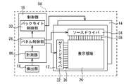
- FIG. 1 is a functional block diagram showing an example of a schematic configuration of a display device as a first embodiment of the present invention.
- FIG. 2 is a schematic diagram showing a schematic configuration of the display panel.
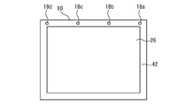
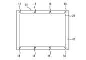
- FIG. 3 is a front view illustrating an example of the display device.
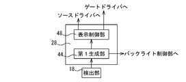
- FIG. 4 is a functional block diagram illustrating an example of a schematic configuration of the panel control unit.
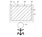
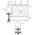
- FIG. 5 is an explanatory diagram illustrating an example of a display area when there is no shielding object between the display device and the observer.
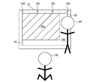
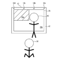
- FIG. 6 is an explanatory diagram illustrating an example of a display area in the case where there is a shield between the display device and the observer.
- FIG. 1 is a functional block diagram showing an example of a schematic configuration of a display device as a first embodiment of the present invention.
- FIG. 2 is a schematic diagram showing a schematic configuration of the display panel.
- FIG. 3 is a front view illustrating an example of the display device.
- FIG. 4 is a functional block
- FIG. 7 is an explanatory diagram illustrating another example of the display area when there is a shield between the display device and the observer.
- FIG. 8 is an explanatory diagram illustrating another example of the display area when there is a shield between the display device and the observer.
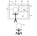
- FIG. 9 is an explanatory diagram illustrating another example of the display area when there is a shield between the display device and the observer.
- FIG. 10 is an explanatory diagram illustrating another example of the display area when there is a shield between the display device and the observer.
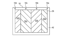
- FIG. 11 is an explanatory diagram illustrating detection areas set in each detection unit.
- FIG. 12 is a front view showing an example of a display device as an application example 1 of the first embodiment of the present invention.
- FIG. 12 is a front view showing an example of a display device as an application example 1 of the first embodiment of the present invention.
- FIG. 13 is a functional block diagram showing an example of a schematic configuration of a display device as an application example 2 of the first embodiment of the present invention.
- FIG. 14 is a front view showing an example of the display device shown in FIG.
- FIG. 15 is a functional block diagram illustrating an example of a schematic configuration of a display device as an application example 3 of the first embodiment of the present invention.
- FIG. 16 is a functional block diagram illustrating an example of a schematic configuration of the panel control unit of the application example 3.
- FIG. 17 is a functional block diagram showing an example of a schematic configuration of a display device as an application example 4 of the first embodiment of the present invention.
- FIG. 18 is a functional block diagram illustrating an example of a schematic configuration of the panel control unit of the application example 4.
- FIG. 14 is a front view showing an example of the display device shown in FIG.
- FIG. 15 is a functional block diagram illustrating an example of a schematic configuration of a display device as an application example 3 of the first embodiment of the present invention.
- FIG. 19 is an explanatory diagram illustrating an example of a display region in the case where a shield exists between the display device and the observer.
- FIG. 20 is an explanatory diagram illustrating another example of the display area when there is a shield between the display device and the observer.
- FIG. 21 is a functional block diagram illustrating an example of a schematic configuration of a display device according to the second embodiment of the present invention.
- FIG. 22 is a functional block diagram illustrating an example of a schematic configuration of a panel control unit employed in the second embodiment.
- FIG. 23 is an explanatory diagram illustrating an example of a display area in the case where there is a shield in front of the display device.
- FIG. 30 is a functional block diagram illustrating an example of a schematic configuration of a panel control unit employed in the third embodiment.
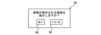
- FIG. 31 is a diagram illustrating an example of a display displayed in the remaining area.
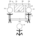
- FIG. 32 is a diagram illustrating an example of two areas set as a display area.
- FIG. 33 is an explanatory diagram illustrating an example of a display area in the case where a shielding object exists between the display device and the observer.
- a display device includes a display panel having a display area, a panel control unit that displays an image in the display area, and a detection unit that detects a shield positioned in front of the display area.
- the panel control unit has a first display area having a display area smaller than the display area when the detection unit detects the shielding object, and the display area when the display area is viewed from the front.
- generated in the position which avoids the said shield which overlaps with (1st structure) is provided.
- a first display area having a display area smaller than the display area is generated in the display area.
- the first display area is generated at a position that avoids an obstacle that overlaps the display area viewed from the front. Therefore, even if there is a shield between the observer and the display device, the observer can see the entire image displayed in the display area.
- the type of the second display area that can be generated in an area excluding the first display area in the display area is excluded from the first display area in the display area.
- the second generation unit generates the second display region based on the type of the second display region input from the input unit. It is the structure to do. In such a configuration, a person located in front of the display area excluding the first display area can select the type of the second display area.
- the fifth configuration is a configuration in which at least one of the position and the size of the second display area can be changed in the third or fourth configuration. In such a configuration, an image displayed in the second display area is easy to see.
- the input unit is configured so that a human being positioned in front of the display area excluding the first display area can perform the second display. It is used when visual information is input to an area, and the visual information input by the input unit is displayed on the first display area and the second display area. In such a configuration, the visual information input to the second display area is visible to the viewer of the first display area.
- the visual information refers to information such as characters and pictures that can be recognized by humans through vision.
- the seventh configuration is a configuration in which the second generation unit generates a plurality of the second display areas in any one of the third to sixth configurations.
- the eighth configuration is a configuration in which a plurality of the detection units are provided in any one of the first to seventh configurations. In such a configuration, the shield is easy to detect.
- the ninth configuration is a configuration in which the display area and the first display area are similar in any one of the first to eighth configurations. In such a configuration, it becomes difficult for the observer to feel uncomfortable when viewing the image displayed in the first display area.
- the tenth configuration is a configuration in which the display area and the second display area are similar in any one of the third to ninth configurations. In such a configuration, it is difficult for a person who becomes a shield for the observer in the first display area to feel uncomfortable when viewing the image displayed in the second display area.
- the eleventh configuration further includes a first measurement unit that measures the time during which the detection unit detects the shielding object in any one of the first to tenth configurations, and the first generation unit
- the first display area is generated at a position that avoids the shield that overlaps the display area when the display area is viewed from the front. It is the structure to do. In such a configuration, for example, it is possible to prevent a person who passes in front of the display area from being determined as a shield. Therefore, the first display area can be generated at an appropriate timing.
- the detection unit detects the shielding object.
- a second measuring unit for measuring the time of the first display area and the first generating unit displays the first display area currently generated when the time measured by the second measuring unit has passed a predetermined time. It is the structure to maintain. In such a configuration, the currently generated first display area is not changed. Therefore, the first display area can be easily used.
- FIG. 1 is a functional block diagram illustrating an example of a schematic configuration of the display device 10.
- FIG. 2 is a schematic diagram showing a schematic configuration of the display panel.
- the display device 10 displays an image. Specific examples of the display device 10 include a home television.
- the display device 10 includes a display panel 12, a backlight 14, a control unit 16, and a detection unit 18.
- the display panel 12 is, for example, a liquid crystal panel, a plasma display panel (PDP), an organic EL (electroluminescence), or the like.
- a transmissive liquid crystal panel is employed as the display panel 12.
- the display panel 12 includes an active matrix substrate 20, a counter substrate 22, and a liquid crystal layer 24 sealed between the active matrix substrate 20 and the counter substrate 22.
- the display panel 12 has a plurality of pixels (not shown).
- the plurality of pixels are formed in a matrix.
- the area where the plurality of pixels are formed becomes the display area 26 (see FIG. 1) of the display panel 12.
- Each pixel may have a plurality of sub-pixels.
- the plurality of sub-pixels are, for example, a red pixel, a green pixel, and a blue pixel.
- the plurality of sub-pixels may include yellow pixels.
- the backlight 14 (see FIG. 1) is disposed behind the display panel 12 (on the side opposite to the observer).
- the backlight 14 irradiates the display area 26 with light.
- the backlight 14 is, for example, a direct type.
- the light source of the backlight 14 is, for example, a light emitting diode.
- Control unit 16 controls display device 10. As shown in FIG. 1, the control unit 16 includes a panel control unit 28 and a backlight control unit 30.
- Panel control unit 28 generates various signals necessary for image display. As shown in FIG. 1, the panel control unit 28 outputs the generated signal to the gate driver 32 and the source driver 34.
- a plurality of gate lines 36 are connected to the gate driver 32.
- Each gate line 36 is connected to a gate electrode of a thin film transistor (not shown).
- the thin film transistor is formed on the active matrix substrate 20.
- the thin film transistor functions as a switching element.
- Each gate line 36 transmits a scanning signal output from the gate driver 32.
- the thin film transistor is driven by the scanning signal input to the gate electrode.
- a plurality of source lines 38 are connected to the source driver 34. Each source line 38 is connected to the source electrode of the thin film transistor. Each source line 38 transmits a display signal output from the source driver 34.
- a display signal is input to the thin film transistor. Thereby, the electric charge according to a display signal is accumulate
- the capacitor is composed of a pixel electrode, a common electrode disposed to face the pixel electrode, and a liquid crystal layer 24 positioned between the pixel electrode and the common electrode.
- the pixel electrode is formed on the active matrix substrate 20. The pixel electrode is connected to the drain electrode of the thin film transistor.
- the common electrode is formed on the counter substrate 22. As the charge corresponding to the display signal is accumulated in the capacitor, the gradation of each pixel is controlled. As a result, the display panel 12 can display an image.
- the backlight control unit 30 controls the backlight 14 based on a signal from the panel control unit 28.
- the detecting unit 18 detects the shielding object 40 (see FIGS. 6 to 10) located in front of the display area 26.
- the shield 40 overlaps the display area 26 when the observer views the display area 26 from the front, for example.
- the shield 40 is not particularly limited as long as it is located in front of the display area 26 and blocks the field of view of the observer 50 (see FIGS. 5 to 10) in the display area 26. For example, it may move like a person or an animal.
- the detection unit 18 is, for example, an illuminance sensor, a distance sensor, or the like.
- the illuminance sensor detects the illuminance in front of the display device 10.
- the illuminance sensor is, for example, a photodiode or a phototransistor.
- the shield 40 When the shield 40 is positioned in front of the illuminance sensor, the illuminance sensor becomes a shadow of the shield 40. For this reason, the illuminance detected by the illuminance sensor decreases.
- the shielding object 40 is present in front of the display device 10.
- the distance sensor measures the distance between the shield 40 and the display device 10.
- the method by which the distance sensor measures the distance is, for example, the TOF (Time of Flight) method.
- the distance sensor includes a light emitting diode.
- the light emitting diode emits near infrared light.
- the distance sensor receives reflected light of near infrared light emitted from the light emitting diode.
- the distance sensor measures the time from when the light emitting diode emits near-infrared light until it receives the reflected light.
- FIG. 1 shows only one detection unit 18 for easy understanding of the drawing, but it is preferable to provide a plurality of detection units 18.
- four detection units 18a to 18d are provided.
- FIG. 3 is a front view of the display device 10.
- four detection units 18a to 18d are arranged in the order of the detection unit 18a, the detection unit 18b, the detection unit 18c, and the detection unit 18d from one end (right end) side of the display device 10.
- the display device 10 includes a housing 42.
- the casing 42 surrounds the display area 26 over the entire circumference.
- the detection units 18a to 18d are exposed to the outside through an opening formed in the housing 42, for example.
- the detection units 18a to 18d are provided above the display area 26 in the example of FIG.
- the detectors 18a to 18d are provided at equal intervals in the horizontal direction of the display area 26 (left and right direction in FIG. 3).
- the detection unit 18a is located at one end of the display area 26 in the horizontal direction.
- the detector 18d is located at the other end of the display area 26 in the horizontal direction.
- the remaining two detectors 18b and 18c are at positions that divide the display area 26 into three equal parts in the horizontal direction.
- Detecting units 18a to 18d output signals. Signals output from the detection units 18a to 18d are input to the panel control unit 28.
- the panel control unit 28 changes the position and size of the area where the image is displayed based on the signals from the detection units 18a to 18d.
- the panel control unit 28 includes a first generation unit 44 and a display control unit 48.
- FIG. 4 is a functional block diagram illustrating an example of a schematic configuration of the panel control unit 28.
- the first generator 44 receives signals from the detectors 18a to 18d. The first generator 44 determines whether or not the signals from the detectors 18a to 18d are equal to or less than a predetermined reference value. This reference value is a criterion for determining whether or not the shield 40 is positioned in front of the display device 10.
- the first generation unit 44 determines that the shielding object 40 is located in front of the display device 10 if the illuminance is equal to or less than the reference value.
- the detection units 18a to 18d are distance sensors, the first generation unit 44 determines that the shielding object 40 is positioned in front of the display device 10 if the distance between the shielding object 40 and the display device 10 is equal to or less than the reference value. To do.
- the plurality of detection units 18a to 18d detect different shielding objects 40.
- the first generation unit 44 may recognize all of the shielding objects detected by the detection units 18a to 18d as the shielding object 40, and among the shielding objects detected by the detection units 18a to 18d, the display device The shield with the shortest distance to 10 may be recognized as the shield 40.
- the first generation unit 44 When the first generation unit 44 receives a signal that is less than or equal to the reference value, the first generation unit 44 identifies a detection unit that has transmitted a signal that is less than or equal to the reference value among the detection units 18a to 18d. The first generation unit 44 sets the position and size of the first display area 26a (see FIGS. 6 to 10) with reference to the specified position of the detection unit.
- FIG. 5 is an explanatory diagram illustrating an example of the display area 26 when the shielding object 40 is not present between the display device 10 and the observer 50.
- 6 to 10 are explanatory diagrams showing examples of the display area 26 in the case where the shielding object 40 exists between the display device 10 and the observer 50, respectively.
- the area where the image is displayed is hatched.
- the human being positioned between the observer 50 and the display device 10 is the shield 40.
- the first display area 26 a is generated in the display area 26.
- the first display area 26 a has a smaller display area than the display area 26.
- the first display area 26a and the display area 26 are preferably similar.
- the aspect ratio of the first display area 26 a is preferably the same as the aspect ratio of the display area 26.
- the display area of the first display area 26 a is 9/16 times as large as the display area 26.
- the horizontal and vertical dimensions are 1 ⁇ 2 of the horizontal and vertical dimensions of the display area 26, as shown in FIGS.
- the display area of the first display area 26 a is 1/4 times as large as the display area 26.
- the size of the first display area 26a is set based on the position of the detection unit specified by the first generation unit 44. Specifically, first, the first generator 44 sets an area in which the first display area 26a can be generated (hereinafter referred to as a generatable area) based on the position of the specified detector.
- the detection area 52a is an area where the shielding object 40 overlaps when the display area 26 is viewed from the front when the detection unit 18a detects the shielding object 40.
- the detection area 52b is an area where the shielding object 40 overlaps when the display area 26 is viewed from the front when the detection unit 18b detects the shielding object 40b.
- the detection area 52c is an area where the shielding object 40 overlaps when the display area 26 is viewed from the front when the detection unit 18c detects the shielding object 40.
- the detection area 52d is an area where the shielding object 40 overlaps when the display area 26 is viewed from the front when the detection unit 18d detects the shielding object 40.
- the first generation unit 44 sequentially receives signals from the four detection units 18a to 18d.
- the first generation unit 44 determines whether or not the received signal is equal to or less than a reference value.
- the first generation unit 44 identifies the detection unit that has transmitted a signal equal to or less than the reference value.
- generation part 44 judges that the shield 40 is located ahead of the detection area corresponding to the specified detection part.
- generation part 44 pinpoints the detection area
- the first generation unit 44 sets an area obtained by removing the specified detection area 52 from the display area 26 as a generation possible area.
- generation part 44 sets the display area of the 1st display area 26a which can be displayed on a generatable area to the display area of the 1st display area 26a. In this way, the size of the first display area 26a is set.
- the first generation unit 44 sets the maximum display area among the display areas of the first display area 26a that can be displayed in the generatable area as the display area of the first display area 26a.
- the detection unit 18a detects the shielding object 40, and the other detection units 18b to 18d do not detect the shielding object 40. Therefore, the detection unit 18a outputs a signal that is less than or equal to the reference value, and the other detection units 18b to 18d output signals that are larger than the reference value.
- generation part 44 specifies that the detection part which transmitted the signal below a reference value is the detection part 18a.
- generation part 44 sets the area
- the display area that can be selected by the first generation unit 44 includes 9/16 times the size of the display region 26 and 1 ⁇ 4 the size of the display region 26.
- the first generation unit 44 sets the size of the display area 26 as 9/16 times the size of the first display area 26a.
- the detection units 18a and 18b detect the shielding object 40, and the other detection units 18c and 18d do not detect the shielding object 40. Therefore, the detection units 18a and 18b output signals that are less than the reference value, and the other detection units 18c and 18d output signals that are larger than the reference value.
- generation part 44 specifies that the detection part which transmitted the signal below a reference value is detection part 18a, 18b.
- generation part 44 sets the area
- the display area that can be selected by the first generation unit 44 is only 1 ⁇ 4 times the display area 26.
- generation part 44 sets the magnitude
- the detection unit 18 b detects the shielding object 40 and the other detection units 18 a, 18 c, and 18 d do not detect the shielding object 40
- the size of the first display region 26 a is the display region 26. Is set to 1/4 times as large as
- the detection units 18 a and 18 d detect the shielding object 40, and the other detection units 18 b and 18 c do not detect the shielding object 40. Therefore, the detection units 18a and 18d output signals that are less than or equal to the reference value, and the other detection units 18b and 18c output signals that are greater than the reference value.
- generation part 44 specifies that the detection part which transmitted the signal below a reference value is detection part 18a, 18d.
- generation part 44 sets the area
- the display area that can be selected by the first generation unit 44 is only 1 ⁇ 4 times the display area 26.
- generation part 44 sets the magnitude
- the detection unit 18d detects the shielding object 40, and the other detection units 18a to 18c do not detect the shielding object 40. Therefore, the detection unit 18d outputs a signal that is equal to or less than the reference value, and the other detection units 18a to 18c output signals that are larger than the reference value.
- generation part 44 specifies that the detection part which transmitted the signal below a reference value is the detection part 18d.
- generation part 44 sets the area
- the display area that can be selected by the first generation unit 44 includes 9/16 times the size of the display region 26 and 1 ⁇ 4 the size of the display region 26.
- the first generation unit 44 sets the size of the display area 26 as 9/16 times the size of the first display area 26a.
- generation part 44 specifies that the detection part which transmitted the signal below a reference value is the detection parts 18c and 18d.
- generation part 44 sets the area
- the display area that can be selected by the first generation unit 44 is only 1 ⁇ 4 times the display area 26.
- generation part 44 sets the magnitude
- the size of the first display area 26 a is the display area 26. Is set to 1/4 times as large as
- the first generation unit 44 cannot secure a generatable region. In this case, the first generation unit 44 does not set the position and size of the first display area 26a. In other words, the first display area 26 a is not generated in the display area 26. Therefore, even if the shield 40 exists between the observer 50 and the display device 10, an image is displayed on the entire display area 26.
- the maximum display area among the display areas of the first display area 26a that can be displayed in the generatable area is set to the display area of the first display area 26a.
- the display area of the first display area 26a does not need to be the maximum display area among the display areas of the first display area 26a that can be displayed in the generatable area.
- the display area of the first display area 26 a may be set to a size that is 1 ⁇ 4 times the display area 26.
- the first generation unit 44 sets a position where the first display area 26a is generated in the display area 26.
- the generation position of the first display area 26a is determined in advance.
- FIGS. 6 and 7 when at least one of the detection units 18 a and 18 b located on one end side from the center of the display area 26 detects the shielding object 40, the first generation unit 44 The generation position of the first display area 26a is set in the upper corner on the other end side. As shown in FIG.
- the first generation unit 44 when each of the detection units 18 a and 18 d located at both ends of the display area 26 detects the shielding object 40, the first generation unit 44 is the horizontal center of the display area 26, In addition, the generation position of the first display area 26 a is set at a position along the upper edge of the display area 26. As shown in FIG. 9 and FIG. 10, when the detection units 18 c and 18 d located on the other end side from the center of the display area 26 detect the shielding object 40, the first generation unit 44 is on one end side of the display area 26. The generation position of the first display area 26a is set at the upper corner.
- the first display area 26 a is generated at a position along the upper edge of the display area 26.
- the position where the first display area 26 a is generated is not limited to the position along the upper edge of the display area 26.
- the first display area 26 a may be generated at a position along the lower edge of the display area 26.
- the first display area 26a may be generated at the center of the display area 26 in the vertical direction (vertical direction in FIGS. 5 to 10).
- the area 26b excluding the first display area 26a in the display area 26 is displayed in black. In other words, an image to be viewed by the observer 50 is not displayed in the region 26b.
- the backlight control unit 30 turns off the area corresponding to the area 26b in the backlight 14 when an image is displayed in the first display area 26a.
- the backlight 14 has a plurality of areas that can be individually lit. Based on the position and size of the first display area 26a set by the first generation unit 44, the backlight control unit 30 lights the backlight 14 for each zone. Specifically, the backlight control unit 30 turns on the area corresponding to the first display area 26 a in the backlight 14 and turns off the area corresponding to the area 26 b in the backlight 14.
- Such a backlight 14 can be realized by, for example, a direct backlight 14 that can be turned on for each light source arranged in a predetermined area.
- the power consumption of the backlight 14 can be suppressed. As a result, the power consumption of the display device 10 is suppressed.
- a normally black mode liquid crystal panel is used as the display panel 12, it is not necessary to apply a voltage when the area 26b is displayed in black. Therefore, the power consumption of the display device 10 is further suppressed.
- Such a display device 10 displays an image in the first display area 26a when the detection unit 18 detects the shielding object 40.
- the first display area 26a is generated at a position avoiding the shield 40 when the display area 26 is viewed from the front. Therefore, even when the shield 40 is positioned between the display device 10 and the viewer 50, the observer 50 can see the entire image displayed in the display area 26 without being interrupted by the shield 40. it can.
- the display device 10 has four detection units 18a to 18d. Therefore, when the display area 26 is viewed from the front, it is possible to accurately detect how much the shield 40 overlaps the display area 26.
- FIG. 12 is a front view showing an example of the display device 54 of this application example.
- the plurality of detection units 18 may be provided not only on the display area 26 but also on the lower side of the display area 26. Thereby, the precision which the detection part 18 detects the shield 40 can be improved.
- the plurality of detection units 18 may be provided only below the display area 26.
- the number of detection units 18 may be less than four or more than four.
- the intervals between the plurality of detection units 18 positioned above the display region 26; The intervals between the plurality of detection units 18 positioned below the display area 26 may be the same or different.
- FIG. 13 is a functional block diagram illustrating an example of a schematic configuration of the display device 56 of the application example.
- FIG. 14 is a front view showing an example of the display device 56 of this application example.
- a camera 58 is employed as the detection unit.
- the camera 58 is, for example, a CCD camera.
- the camera 58 images the observer 50.
- the camera 58 is provided above the display area 26 and at the center in the horizontal direction of the display area 26, but the position of the camera 58 is limited to the position shown in FIG. Not.
- a camera 58 is employed as the detection unit. Therefore, it is easy to grasp the position of the shield 40.
- FIG. 15 is a functional block diagram illustrating an example of a schematic configuration of the display device 80 of the application example.
- FIG. 16 is a functional block diagram illustrating an example of a schematic configuration of the panel control unit 28 of the application example.
- the control unit 16 includes a measurement unit 82.
- the measurement unit 82 measures the time during which the detection unit 18 detects the shielding object 40 (see, for example, FIG. 6).
- the measurement unit 82 functions as a first measurement unit.
- the measurement unit 82 receives signals sequentially from the four detection units 18a to 18d (see FIG. 1). The measuring unit 82 determines whether or not the received signal is equal to or less than a reference value. When the measurement unit 82 determines that the received signal is equal to or less than the reference value, the measurement unit 82 identifies the detection unit that has transmitted a signal equal to or less than the reference value. The measurement unit 82 measures the time during which the signal from the identified detection unit is less than or equal to the reference value. When the time from which the signal from the specified detection unit is equal to or less than the reference value has elapsed for a predetermined time (for example, 5 seconds), the measurement unit 82 has the shielding object 40 in front of the detection region corresponding to the specified detection unit.
- a predetermined time for example, 5 seconds
- the measurement unit 82 outputs a signal indicating that the shielding object 40 is located in front of the detection region corresponding to the specified detection unit to the first generation unit 44.
- generation part 44 pinpoints the detection area
- the first generation unit 44 sets an area obtained by removing the identified detection area from the display area 26 as a generation possible area.
- generation part 44 sets the display area of the 1st display area 26a which can be displayed on a generatable area to the display area of the 1st display area 26a. In this way, the size of the first display area 26a is set.
- the first generation unit 44 sets a position where the first display area 26 a is generated in the display area 26. Then, the first generation unit 44 generates the first display area 26a in the display area 26 based on the set position and size of the first display area 26a.
- the display control unit 48 displays an image in the first display area 26 a generated by the first generation unit 46.
- FIG. 17 is a functional block diagram illustrating an example of a schematic configuration of the display device 84 of the application example.
- FIG. 18 is a functional block diagram illustrating an example of a schematic configuration of the panel control unit 28 of the application example.
- the control unit 16 includes a measurement unit 86.
- the measurement unit 86 measures the time during which the detection unit 18 is detecting the shield 40 (for example, see FIG. 6).
- the measurement unit 86 functions as a second measurement unit.
- the first generator 44 sequentially receives signals from the four detectors 18a to 18d (see FIG. 1). The first generation unit 44 determines whether or not the received signal is equal to or less than a reference value. When the first generation unit 44 determines that the received signal is equal to or less than the reference value, the first generation unit 44 identifies the detection unit that has transmitted a signal equal to or less than the reference value. The 1st production
- generation part 44 sets the display area of the 1st display area 26a which can be displayed on a generatable area to the display area of the 1st display area 26a. In this way, the size of the first display area 26a is set. In addition, the first generation unit 44 sets a position where the first display area 26 a is generated in the display area 26. Then, the first generation unit 44 generates the first display area 26a in the display area 26 based on the set position and size of the first display area 26a. The display control unit 48 displays an image in the first display area 26 a generated by the first generation unit 46.
- the first generation unit 44 transmits a signal indicating the specified detection unit to the measurement unit 86 after generating the first display region 26a in the display region 26a.
- the measurement unit 86 receives a signal from the detection unit specified by the first generation unit 44. At this time, the measurement unit 86 may receive a signal from a detection unit that is not specified by the first generation unit 44.
- the measurement unit 86 measures the time during which the signal from the detection unit specified by the first generation unit 44 is equal to or less than the reference value. When the time from which the signal from the detection part which the 1st production
- the first generation unit 44 receives the signal from the measurement unit 86, the first generation unit 44 maintains the currently generated first display area 26a.
- the first generation unit 44 stops generating the first display area 26a when the signal from the identified detection unit becomes larger than the reference value. Note that the first generation unit 44 may stop generating the first display area 26a when a predetermined time (for example, 1 minute) elapses when the signal from the identified detection unit becomes larger than the reference value.
- a predetermined time for example, 1 minute
- the first display area 26a when there is a person (the shield 40) in front of the display area 26, the first display area 26a is generated.
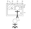
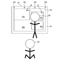
- the first display area 26a maintains the current position and size. Therefore, for example, as shown in FIG. 19, even if another person 88 stands in front of the first display area 26a, or as shown in FIG.
- the position and size of the first display area 26a are not changed even if a hand or the like is put out in front of the first display area 26a. As a result, the first display area 26a can be easily used.
- FIG. 21 is a functional block diagram illustrating an example of a schematic configuration of the display device 60 of the present embodiment.
- FIG. 22 is a functional block diagram illustrating an example of a schematic configuration of the panel control unit 62 employed in the present embodiment.
- FIG. 23 is an explanatory diagram illustrating an example of the display area 26 when the shield 40 is present in front of the display device 60.
- the display device 60 of the present embodiment includes a touch panel 64 as compared to the display device 10 of the first embodiment, as shown in FIGS.
- the touch panel 64 is disposed on the viewer 50 side of the display panel 12.
- the touch panel 64 is, for example, a capacitive touch panel.
- the second generation unit 66 sets the position and size of the second display area 26c (see FIG. 23) displayed in the area 26b.
- the second display area 26c has a smaller display area than the area 26b.
- the second display area 26c is preferably similar to the first display area 26a.
- the aspect ratio of the second display area 26c is preferably the same as the aspect ratio of the first display area 26a. This makes it difficult for a person (the shield 40) located in front of the area 26b to feel uncomfortable when viewing the image displayed in the second display area 26c.
- an image for viewing by a human (the shield 40) located in front of the area 26b is displayed.
- the observer in the second display area 26c becomes the shield 40 for the observer 50 in the first display area 26a.
- a person (shielding object 40) located in front of the area 26b touches an area corresponding to the area 26b on the touch panel 64.
- a signal from the touch panel 64 is input to the second generation unit 66.
- the second generation unit 66 sets the position and size of the second display area 26c according to the shape and size of the area 26b.
- an appropriate size may be selected from a plurality of predetermined sizes, or a size corresponding to the shape and size of the area 26b may be set as appropriate.
- an appropriate position may be selected from a plurality of predetermined positions.
- the second display area 26c is an area corresponding to the area 26b on the touch panel 64 and the front of the area 26b. It is also possible to include a position touched by a person (shielding object 40) located in the position.
- the position and / or size of the second display area 26c may be changeable.
- a method for changing the position of the second display area 26c for example, a person (shielding object 40) located in front of the area 26b touches an area corresponding to the second display area 26c with the finger on the touch panel 64, and the state It is possible to adopt a method of moving a finger while maintaining the above.
- a method for changing the size of the second display area 26c for example, a person (the shield 40) located in front of the area 26b touches the area corresponding to the second display area 26c on the touch panel 64 with two fingers. A method of changing the interval between these two fingers while maintaining the state can be adopted.
- the second generation unit 66 generates the second display area 26c in the area 26b based on the set position and size of the second display area 26c.
- the display control unit 48 (see FIG. 22) displays an image in the second display area 26c generated by the second generation unit 68.
- the touch panel 64 functions as an input unit.
- an image is displayed in the second display area 26c. Therefore, not only the observer 50 but also a person (shielding object 40) located in front of the area 26b can see the entire image displayed in the display area 26.
- the second display area 26c is displayed in the area 26b.
- the power consumption of the display device 10 can be suppressed as compared with the case where the second display area 26c is always displayed in the area 26b.
- FIG. 24 is a functional block diagram showing an example of the panel control unit 62 employed in this application example.
- FIG. 25 is a diagram illustrating an example of the options 70 displayed in the area 26b.
- the second generation unit 66 when a signal from the touch panel 64 is input, the second generation unit 66 causes the display control unit 48 to display an option 70 (see FIG. 25) indicating the size of the selectable second display area 26c. .
- the person (the shield 40) positioned in front of the area 26b selects an appropriate option 70 from the options 70 displayed in the area 26b.
- This selection operation is realized by touching an area corresponding to the option 70 on the touch panel 64, for example.
- the touch panel 64 functions as an input unit.
- the area 26b displaying the option 70 functions as a notification unit.
- the size of the selectable second display area 26c is notified to a human (the shield 40) located in front of the area 26b.
- a human (the shield 40) positioned in front of the area 26b can select the size of the second display area 26c.
- the size of the selectable second display area 26c may be notified by voice. This sound is output from a speaker included in the display device.
- FIG. 26 is a functional block diagram illustrating an example of a schematic configuration of the panel control unit 62 employed in this application example.
- FIG. 27 is an explanatory diagram illustrating an example of the display area 26 when the shield 40 is present in front of the display device 72 according to this application example.
- a signal from the touch panel 64 is input to the display control unit 48.
- the display control unit 48 displays the visual information 74 input from the touch panel 64 functioning as an information input unit in the first display area 26a and the second display area 26c.
- the size of the visual information 74 is changed in accordance with the area ratio between the first display area 26a and the second display area 26c.
- FIG. 28 is an explanatory diagram illustrating an example of the display area 26 when the shield 40 is present in front of the display device 74 of the application example.
- a plurality of second display areas 26c and 26d are generated in the area 26b.
- the same image is displayed in the first display area 26a and the second display area 26c, but an image different from the image displayed in the first display area 26a and the second display area 26c is displayed in the second display area. 26d.
- a person located in front of the remaining area 26b writes characters or the like in the second display area 26c while viewing the image in the second display area 26d. Characters and the like written in the second display area 26c are displayed in the first display area 26a. Such usage is conceivable.
- FIG. 29 is a functional block diagram illustrating an example of a schematic configuration of the display device 90 of the present embodiment.
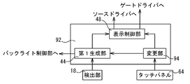
- FIG. 30 is a functional block diagram illustrating an example of a schematic configuration of the panel control unit 92 of the present embodiment.
- the control device 90 includes a touch panel 64.
- the panel control unit 92 includes a changing unit 94.
- the touch panel 64 transmits a signal to the changing unit 94.
- the changing unit 94 causes the display control unit 48 to display a display 96 (see FIG. 31) for confirming whether to reduce the area in which the image is displayed.
- the display 96 is displayed in the area 26b.
- the display 96 is displayed at a position touched by a person (the shield 40) in the region 26b, for example.
- the display 96 includes options 98.
- Person (shielding object 40) decides whether to reduce the area where the image is displayed. This decision is realized by touching an area corresponding to the option 98 on the touch panel 64, for example.
- a signal is input from the touch panel 64 to the changing unit 94.
- the change unit 94 receives a signal from the touch panel 64, the change unit 94 transmits the signal to the display control unit 48. This signal indicates that the detection area corresponding to the detection unit that has detected the person (the shield 40) is not excluded from the area where the first display area 26a can be generated.
- a signal is input from the touch panel 64 to the changing unit 94.
- the change unit 94 receives a signal from the touch panel 64, the change unit 94 transmits a signal to the first generation unit 44. This signal indicates that the detection area corresponding to the detection unit that has detected the person (the shield 40) is not excluded from the area where the first display area 26a can be generated.
- the first display area 26a disappears. As a result, an image is displayed on the entire display area 26. Thereafter, even if a person (the shield 40) is present in front of the area 100b (see FIG. 32), the first display area 26a is not generated. Therefore, the front of the region 100b can be used freely. For example, a person stands in front of an image displayed on the entire display area 26. As a result, the contents of the image can be described using an image larger than the image displayed in the first display area 26a.
- the first display area 26a is generated at a position that avoids another person (the shielding object 102) in the area 100a.
- the detection unit 18d detects another person (the shielding object 102).
- the first display area 26a is generated in an area (area corresponding to the detection areas 52b and 52c) excluding the detection area 52d (see FIG. 11) in the area 100a.
- paper may be attached to the region 100b. This paper does not interfere with the first display area 26a.
- the following method is conceivable.
- the change unit 94 receives a signal from the touch panel 64, the change unit 94 transmits a signal to the first generation unit 44 and the display control unit 48. This signal indicates that the settings of the areas 100a and 100b in the display area 26 are cancelled. As a result, the settings of the areas 100a and 100b in the display area 26 are cancelled.
- the display 96 need not be displayed in the area 26b.
- the display 96 may be displayed in the display area 26 before the area 26 b is generated in the display area 26.
- a person may be able to set the size of the area 100b.
- a method of setting the size of the region 100b for example, there is a method of selecting from several preset sizes.
- a person may be able to set the position where the region 100b is formed.
- a method for setting the formation position of the region 100b for example, there is a method in which a position touched by a person with a finger or the like is used as the center of the region 100b.
- the size of the first display area 26a is determined in advance, but the size of the first display area 26a is not necessarily determined in advance.
- the display device may have a multi-screen function for simultaneously displaying a plurality of images.
- the display device has a higher resolution.
- the resolution of the first display area is set to Full-HD resolution. Can be equivalent.
- the display panel may have an optical sensor.
- the optical sensor includes, for example, a photodiode.
- the optical sensor functions as a detection unit. In this case, for example, when paper or the like is pasted on the display area, an area where the first display area can be generated can be set except for the area pasted on paper or the like.
Landscapes
- Engineering & Computer Science (AREA)
- Physics & Mathematics (AREA)
- Computer Hardware Design (AREA)
- General Physics & Mathematics (AREA)
- Theoretical Computer Science (AREA)
- Controls And Circuits For Display Device (AREA)
- Devices For Indicating Variable Information By Combining Individual Elements (AREA)
- Liquid Crystal Display Device Control (AREA)
- Control Of Indicators Other Than Cathode Ray Tubes (AREA)
Abstract
観察者と表示装置との間に遮蔽物が存在する場合であっても、表示領域に表示される画像の全体を見ることが容易な表示装置を提供することを、目的とする。表示領域(26)を有する表示パネル(12)と、表示領域(26)に画像を表示するパネル制御部(28)と、表示領域(26)の前方に位置する遮蔽物(40)を検出する検出部(18)とを備え、パネル制御部(28)は、検出部(18)が遮蔽物(40)を検出した場合に、表示領域(26)よりも小さい表示面積を有する第1表示領域(26a)を、表示領域(26)を正面から見たときに表示領域(26)と重なる遮蔽物(40)を避ける位置に生成する第1生成部(44)を備える。
Description
本発明は、画像が表示される領域を変更可能な表示装置に関する。
近年、表示装置の表示領域が大型化している。表示領域が大きい場合、観察者は、表示装置からある程度離れた位置で、表示領域に表示される画像を見る。
観察者が表示装置から離れると、観察者と表示装置との間に、例えば人間等の遮蔽物が存在する場合がある。この場合、観察者は表示領域の全体を見ることができない。そのため、観察者は、例えば場所を移動する等して、表示領域に表示される画像を見ることになる。
特開2008-197447号公報には、大画面表示装置が開示されている。この大画面表示装置は、不特定視聴者向けの情報を表示するパブリック表示エリアを有する。パブリック表示エリアの前に特定視聴者が立つと、特定視聴者向けの情報を表示するプライベート表示エリアが生成される。プライベート表示エリアは、特定視聴者の体形に合わせて生成される。プライベート表示エリアが生成されると、大画面表示装置の表示画面においてプライベート表示エリアを除いた領域がパブリック表示エリアになる。そのため、パブリック表示エリアが歪な形になる。その結果、パブリック表示エリアに表示される情報が見難くなる。
本発明の目的は、観察者と表示装置との間に遮蔽物が存在する場合であっても、表示領域に表示される画像の全体を見ることが容易な表示装置を提供することである。
本発明の表示装置は、表示領域を有する表示パネルと、前記表示領域に画像を表示するパネル制御部と、前記表示領域の前方に位置する遮蔽物を検出する検出部とを備え、前記パネル制御部は、前記検出部が前記遮蔽物を検出した場合に、前記表示領域よりも小さい表示面積を有する第1表示領域を、前記表示領域を正面から見たときに前記表示領域と重なる前記遮蔽物を避ける位置に生成する第1生成部を備える。
本発明の表示装置は、観察者と表示装置との間に遮蔽物が存在する場合であっても、表示領域に表示される画像の全体を見ることが容易になる。
本発明の一実施形態に係る表示装置は、表示領域を有する表示パネルと、前記表示領域に画像を表示するパネル制御部と、前記表示領域の前方に位置する遮蔽物を検出する検出部とを備え、前記パネル制御部は、前記検出部が前記遮蔽物を検出した場合に、前記表示領域よりも小さい表示面積を有する第1表示領域を、前記表示領域を正面から見たときに前記表示領域と重なる前記遮蔽物を避ける位置に生成する第1生成部を備える(第1の構成)。
第1の構成においては、検出部が遮蔽物を検出した場合に、表示領域よりも小さい表示面積を有する第1表示領域が表示領域に生成される。第1表示領域は、正面から見た表示領域と重なる遮蔽物を避ける位置に生成される。そのため、観察者と表示装置との間に遮蔽物が存在する場合であっても、表示領域に表示される画像の全体を、観察者は見ることができる。
第2の構成は、前記第1の構成において、前記表示パネルの後方に配置され、前記表示パネルに光を照射するバックライトをさらに備え、前記バックライトは、前記表示領域における前記第1表示領域を除いた領域と対応する区域が消灯可能になっている構成である。このような構成においては、第1表示領域に画像が表示されているときに、バックライトにおいて表示領域における第1表示領域を除いた領域と対応する区域が消灯されるようにすれば、表示装置の消費電力が抑えられる。
第3の構成は、前記第1又は第2の構成において、前記表示領域における前記第1表示領域を除いた領域よりも小さい表示面積を有する第2表示領域を前記表示領域における前記第1表示領域を除いた領域に生成するときに、前記表示領域における前記第1表示領域を除いた領域の前方に位置する人間が操作する入力部をさらに備え、前記パネル制御部は、前記入力部によって入力された内容に基づいて、前記第2表示領域を生成する第2生成部をさらに備える構成である。このような構成においては、表示領域における第1表示領域を除いた領域に生成される第2表示領域が、第1表示領域の観察者にとって遮蔽物となる人間の表示領域として、利用できる。
第4の構成は、前記第3の構成において、前記表示領域における前記第1表示領域を除いた領域に生成可能な前記第2表示領域の種類を、前記表示領域における前記第1表示領域を除いた領域の前方に位置する人間に報知する報知部をさらに備え、前記入力部は、前記報知部が報知する前記第2表示領域の種類から選択した種類を、前記表示領域における前記第1表示領域を除いた領域の前方に位置する人間が入力するときに用いられ、前記第2生成部は、前記入力部から入力された前記第2表示領域の種類に基づいて、前記第2表示領域を生成する構成である。このような構成においては、表示領域における第1表示領域を除いた領域の前方に位置する人間が、第2表示領域の種類を選択できる。
第5の構成は、前記第3又は第4の構成において、前記第2表示領域の位置及びサイズの少なくとも一方が変更可能になっている構成である。このような構成においては、第2表示領域に表示される画像が見易くなる。
第6の構成は、前記第3~第5の構成の何れか1つにおいて、前記入力部は、前記表示領域における前記第1表示領域を除いた領域の前方に位置する人間が前記第2表示領域に視覚情報を入力するときに用いられ、前記入力部によって入力された視覚情報が、前記第1表示領域と前記第2表示領域とに表示される構成である。このような構成においては、第2表示領域に入力された視覚情報が、第1表示領域の観察者に見える。ここで、視覚情報とは、例えば、視覚を通じて人間が認識できる文字、絵等の情報をいう。
第7の構成は、前記第3~第6の構成の何れか1つにおいて、前記第2生成部は、前記第2表示領域を複数生成する構成である。
第8の構成は、前記第1~第7の構成の何れか1つにおいて、前記検出部が複数設けられている構成である。このような構成においては、遮蔽物が検出し易い。
第9の構成は、前記第1~第8の構成の何れか1つにおいて、前記表示領域と、前記第1表示領域とが、相似形である構成である。このような構成においては、観察者が、第1表示領域に表示される画像を見たときに、違和感を感じ難くなる。
第10の構成は、前記第3~第9の構成の何れか1つにおいて、前記表示領域と、前記第2表示領域とが、相似形である構成である。このような構成においては、第1表示領域の観察者にとって遮蔽物となる人間が、第2表示領域に表示される画像を見たときに、違和感を感じ難くなる。
第11の構成は、前記第1~第10の構成の何れか1つにおいて、前記検出部が前記遮蔽物を検出している時間を計測する第1計測部をさらに備え、前記第1生成部は、前記第1計測部が計測した時間が所定時間を経過した場合に、前記第1表示領域を、前記表示領域を正面から見たときに前記表示領域と重なる前記遮蔽物を避ける位置に生成する構成である。このような構成においては、例えば、表示領域の前方を通過する人間が遮蔽物と判断されるのを防ぐことができる。そのため、適正なタイミングで第1表示領域を生成することができる。
第12の構成は、前記第1~第11の構成の何れか1つにおいて、前記第1生成部が前記第1表示領域を生成しているときに、前記検出部が前記遮蔽物を検出している時間を計測する第2計測部をさらに備え、前記第1生成部は、前記第2計測部が計測した時間が所定時間を経過した場合に、現在生成している前記第1表示領域を維持する構成である。このような構成においては、現在生成している第1表示領域が変更されない。そのため、第1表示領域が利用し易くなる。
第13の構成は、前記第1~第12の構成の何れか1つにおいて、前記パネル制御部は、前記表示領域において前記第1表示領域が生成され得る領域を変更する変更部をさらに備える構成である。このような構成においては、例えば、第1表示領域を生成可能な領域が表示領域よりも狭くなると、表示領域において第1表示領域が形成されない領域が生成される。この領域の前方は、例えば、第1表示領域に表示される画像を説明するための人が立つスペースとして利用できる。また、例えば、この領域に紙等を貼り付けることもできる。そのため、表示装置の利便性が高まる。
以下、本発明のより具体的な実施形態について、図面を参照しながら説明する。なお、以下で参照する各図は、説明の便宜上、本発明の実施形態の構成部材のうち、本発明を説明するために必要な主要部材のみを簡略化して示したものである。従って、本発明に係る表示装置は、本明細書が参照する各図に示されていない任意の構成部材を備え得る。また、図中同一又は相当部分には、同一符号を付して、その説明は繰り返さない。
[第1の実施形態]
図1,図2を参照して、本発明の第1の実施形態としての表示装置10について説明する。図1は、表示装置10の概略構成の一例を示す機能ブロック図である。図2は、表示パネルの概略構成を示す模式図である。
図1,図2を参照して、本発明の第1の実施形態としての表示装置10について説明する。図1は、表示装置10の概略構成の一例を示す機能ブロック図である。図2は、表示パネルの概略構成を示す模式図である。
[全体構成]
表示装置10は、画像を表示する。表示装置10の具体例としては、例えば、家庭用テレビ等がある。表示装置10は、表示パネル12と、バックライト14と、制御部16と、検出部18とを備える。
表示装置10は、画像を表示する。表示装置10の具体例としては、例えば、家庭用テレビ等がある。表示装置10は、表示パネル12と、バックライト14と、制御部16と、検出部18とを備える。
表示パネル12は、例えば、液晶パネル、プラズマディスプレイパネル(PDP)、有機EL(electroluminescence)等である。本実施形態では、表示パネル12として、透過型の液晶パネルが採用されている。
図2に示すように、表示パネル12は、アクティブマトリクス基板20と、対向基板22と、これらアクティブマトリクス基板20と対向基板22との間に封入された液晶層24とを備える。
表示パネル12は、複数の画素(図示せず)を有する。複数の画素は、マトリクス状に形成されている。複数の画素が形成された領域は、表示パネル12の表示領域26(図1参照)になる。
各画素は、複数のサブ画素を有してもよい。複数のサブ画素は、例えば、赤色画素、緑色画素及び青色画素である。複数のサブ画素は、黄色画素を含んでもよい。
バックライト14(図1参照)は、表示パネル12の後方(観察者とは反対側)に配置される。バックライト14は、表示領域26に光を照射する。バックライト14は、例えば、直下型である。バックライト14の光源は、例えば、発光ダイオードである。
制御部16(図1参照)は、表示装置10を制御する。制御部16は、図1に示すように、パネル制御部28と、バックライト制御部30とを備える。
パネル制御部28は、画像表示に必要な各種信号を生成する。図1に示すように、パネル制御部28は、ゲートドライバ32とソースドライバ34に対して、生成した信号を出力する。
ゲートドライバ32には、複数のゲート線36が接続されている。各ゲート線36は、薄膜トランジスタ(図示せず)のゲート電極に接続されている。薄膜トランジスタは、アクティブマトリクス基板20上に形成されている。薄膜トランジスタは、スイッチング素子として機能する。各ゲート線36は、ゲートドライバ32から出力される走査信号を伝送する。ゲート電極に入力される走査信号によって、薄膜トランジスタが駆動される。
ソースドライバ34には、複数のソース線38が接続されている。各ソース線38は、薄膜トランジスタのソース電極に接続されている。各ソース線38は、ソースドライバ34から出力される表示信号を伝送する。薄膜トランジスタが駆動されているときに、薄膜トランジスタに表示信号が入力される。これにより、表示信号に応じた電荷が、薄膜トランジスタに接続された容量に蓄積される。容量は、画素電極と、画素電極に対向して配置された共通電極と、これら画素電極と共通電極との間に位置する液晶層24とによって構成される。画素電極は、アクティブマトリクス基板20に形成されている。画素電極は、薄膜トランジスタのドレイン電極に接続されている。共通電極は、対向基板22に形成されている。表示信号に応じた電荷が容量に蓄積されることにより、各画素の階調が制御される。その結果、表示パネル12は、画像を表示することができる。
バックライト制御部30は、パネル制御部28からの信号に基づいて、バックライト14を制御する。
検出部18は、表示領域26の前方に位置する遮蔽物40(図6~図10参照)を検出する。遮蔽物40は、例えば、観察者が表示領域26を正面から見たときに、表示領域26と重なるものである。遮蔽物40は、表示領域26の前方に位置し、表示領域26の観察者50(図5~図10参照)の視界を遮るものであれば、特に限定されない。例えば、人や動物のように動くものであっても良い。
検出部18は、例えば、照度センサ、距離センサ等である。照度センサは、表示装置10の前方の照度を検出する。照度センサは、例えば、フォトダイオード、フォトトランジスタ等である。遮蔽物40が照度センサの前方に位置すると、照度センサは遮蔽物40の影になる。そのため、照度センサが検出する照度は低下する。照度が予め定められた基準値以下になると、表示装置10の前方に遮蔽物40が存在することになる。
距離センサは、遮蔽物40と表示装置10との距離を測定する。距離センサが距離を測定する方式は、例えば、TOF(Time of Flight)方式である。具体的には、例えば、距離センサは発光ダイオードを備える。発光ダイオードは近赤外光を発する。距離センサは、発光ダイオードが発した近赤外光の反射光を受光する。距離センサは、発光ダイオードが近赤外光を発してからその反射光を受光するまでの時間を計測する。距離センサは、計測された時間から遮蔽物40との距離を求める。測定距離が予め定められた基準値以下になると、表示装置10の前方に遮蔽物40が存在することになる。
図1では、図面を判り易くするために、1つの検出部18だけを示しているが、複数の検出部18を設けることが好ましい。例えば、図3の例では、4つの検出部18a~18dが設けられている。図3は、表示装置10の正面図である。図3の例では、表示装置10の一端(右端)側から検出部18a、検出部18b、検出部18c、検出部18dの順に、4つの検出部18a~18dが並んでいる。
図3に示すように、表示装置10は、筺体42を備える。筺体42は、表示領域26を全周に亘って囲む。検出部18a~18dは、例えば、筺体42に形成された開口を通じて、外部に露出されている。
検出部18a~18dは、図3の例では、表示領域26よりも上側に設けられている。検出部18a~18dは、表示領域26の水平方向(図3の左右方向)に等間隔に設けられている。検出部18aは、表示領域26の水平方向の一端に位置する。検出部18dは、表示領域26の水平方向の他端に位置する。残りの2つの検出部18b,18cは、表示領域26を水平方向に3等分する位置にある。
検出部18a~18dは信号を出力する。検出部18a~18dが出力する信号は、パネル制御部28に入力される。パネル制御部28は、検出部18a~18dからの信号に基づいて、画像が表示される領域の位置及びサイズを変更する。パネル制御部28は、図4に示すように、第1生成部44と、表示制御部48とを備える。図4は、パネル制御部28の概略構成の一例を示す機能ブロック図である。
第1生成部44は、検出部18a~18dからの信号を受信する。第1生成部44は、検出部18a~18dからの信号が予め定められた基準値以下であるか否かを判定する。この基準値は、表示装置10の前方に遮蔽物40が位置するか否かの判断基準となる。
検出部18a~18dが照度センサである場合、照度が基準値以下であれば、表示装置10の前方に遮蔽物40が位置すると、第1生成部44が判断する。検出部18a~18dが距離センサである場合、遮蔽物40と表示装置10との距離が基準値以下であれば、表示装置10の前方に遮蔽物40が位置すると、第1生成部44が判断する。
複数の検出部18a~18dが互いに異なる遮蔽物40を検出する場合がある。この場合、第1生成部44は、検出部18a~18dが検出した遮蔽物の全てを、遮蔽物40と認識してもよいし、検出部18a~18dが検出した遮蔽物のうち、表示装置10との距離が最も短い遮蔽物を、遮蔽物40と認識してもよい。
第1生成部44は、基準値以下の信号を受信した場合、検出部18a~18dのうち、基準値以下の信号を送ってきた検出部を特定する。第1生成部44は、特定した検出部の位置を参照して、第1表示領域26a(図6~図10参照)の位置及びサイズを設定する。
図5~図10を参照しながら、第1生成部44が第1表示領域26aの位置及びサイズを設定する方法について説明する。図5は、表示装置10と観察者50との間に遮蔽物40が存在しない場合の表示領域26の一例を示す説明図である。図6~図10は、それぞれ、表示装置10と観察者50との間に遮蔽物40が存在する場合の表示領域26の一例を示す説明図である。図5~図10では、画像が表示される領域にハッチングを付している。図6~図10では、観察者50と表示装置10との間に位置する人間が、遮蔽物40になっている。
図5に示すように、観察者50と表示装置10との間に遮蔽物40が存在しない場合、表示領域26の全体に画像が表示される。そのため、観察者50は、表示領域26の全体に表示される画像を見ることができる。
図6~図10に示すように、観察者50と表示装置10との間に遮蔽物40が存在する場合、第1表示領域26aが表示領域26に生成される。第1表示領域26aは、表示領域26よりも小さい表示面積を有する。第1表示領域26aと、表示領域26とは、相似形であることが好ましい。換言すれば、第1表示領域26aの縦横比は、表示領域26の縦横比と同じであることが好ましい。これにより、第1表示領域26aに画像が表示されるようになっても、観察者50は違和感を感じ難い。
本実施形態では、第1表示領域26aのサイズは2種類ある。1つは、図6及び図9に示すように、水平方向(図6~図10の左右方向)及び垂直方向(図6~図10の上下方向)の寸法が、表示領域26の水平方向及び垂直方向の寸法の3/4になっている。この場合、第1表示領域26aの表示面積は、表示領域26の9/16倍の大きさになる。もう1つは、図7,図8及び図10に示すように、水平方向及び垂直方向の寸法が、表示領域26の水平方向及び垂直方向の寸法の1/2になっている。この場合、第1表示領域26aの表示面積は、表示領域26の1/4倍の大きさになる。
第1表示領域26aのサイズは、第1生成部44が特定した検出部の位置に基づいて設定される。具体的には、先ず、第1生成部44は、特定した検出部の位置に基づいて、第1表示領域26aが生成可能な領域(以下、生成可能領域)を設定する。
図11を参照しながら、第1生成部44が生成可能領域を設定する方法について説明する。図11の例では、4つの検出領域52a~52dが表示領域26の水平方向(図11の左右方向)に並んでいる。検出領域52aは、検出部18aが遮蔽物40を検出したときに、表示領域26を正面から見ると、遮蔽物40が重なる領域である。検出領域52bは、検出部18bが遮蔽物40を検出したときに、表示領域26を正面から見ると、遮蔽物40が重なる領域である。検出領域52cは、検出部18cが遮蔽物40を検出したときに、表示領域26を正面から見ると、遮蔽物40が重なる領域である。検出領域52dは、検出部18dが遮蔽物40を検出したときに、表示領域26を正面から見ると、遮蔽物40が重なる領域である。
第1生成部44は、4つの検出部18a~18dから順次信号を受信する。第1生成部44は、受信した信号が基準値以下であるか否かを判断する。第1生成部44は、受信した信号が基準値以下であると判断した場合、当該基準値以下の信号を送ってきた検出部を特定する。第1生成部44は、特定した検出部と対応する検出領域の前方に、遮蔽物40が位置すると判断する。第1生成部44は、表示領域26を正面から見たときに遮蔽物40が重なる検出領域を特定する。第1生成部44は、特定した検出領域52を表示領域26から除いた領域を、生成可能領域に設定する。第1生成部44は、生成可能領域に表示可能な第1表示領域26aの表示面積を、第1表示領域26aの表示面積に設定する。このようにして、第1表示領域26aのサイズが設定される。
本実施形態では、第1生成部44は、生成可能領域に表示可能な第1表示領域26aの表示面積のうち、最大の表示面積を、第1表示領域26aの表示面積に設定する。
図6に示すように、遮蔽物40が表示領域26の一端(図6の右端)の前方に位置する場合を考える。この場合、検出部18aが遮蔽物40を検出し、他の検出部18b~18dは遮蔽物40を検出しない。そのため、検出部18aは基準値以下の信号を出力し、他の検出部18b~18dは基準値より大きい信号を出力する。第1生成部44は、基準値以下の信号を送信してきた検出部が検出部18aであると特定する。第1生成部44は、検出部18aに対応する検出領域52aを表示領域26から除いた領域を、生成可能領域に設定する。この場合、第1生成部44が選択可能な表示面積には、表示領域26の9/16倍の大きさと、表示領域26の1/4の大きさとがある。第1生成部44は、第1表示領域26aのサイズとして、表示領域26の9/16倍の大きさを設定する。
図7に示すように、遮蔽物40が図6よりも表示領域26の中央寄りに位置する場合を考える。この場合、検出部18a,18bが遮蔽物40を検出し、他の検出部18c,18dは遮蔽物40を検出しない。そのため、検出部18a,18bは基準値以下の信号を出力し、他の検出部18c,18dは基準値より大きい信号を出力する。第1生成部44は、基準値以下の信号を送信してきた検出部が検出部18a,18bであると特定する。第1生成部44は、検出部18a,18bに対応する検出領域52a,52bを表示領域26から除いた領域を、生成可能領域に設定する。この場合、第1生成部44が選択可能な表示面積は、表示領域26の1/4倍の大きさだけである。第1生成部44は、第1表示領域26aのサイズとして、表示領域26の1/4倍の大きさを設定する。なお、図7に示す例において、検出部18bが遮蔽物40を検出し、他の検出部18a、18c、18dが遮蔽物40を検出しない場合、第1表示領域26aのサイズは、表示領域26の1/4倍の大きさに設定される。
図8に示すように、遮蔽物40が表示領域26の水平方向両端(図8の左右端)の前方に位置する場合を考える。この場合、検出部18a,18dが遮蔽物40を検出し、他の検出部18b,18cは遮蔽物40を検出しない。そのため、検出部18a,18dが基準値以下の信号を出力し、他の検出部18b,18cは基準値より大きい信号を出力する。第1生成部44は、基準値以下の信号を送信してきた検出部が検出部18a,18dであると特定する。第1生成部44は、検出部18a,18dに対応する検出領域52a,52dを表示領域26から除いた領域を、生成可能領域に設定する。この場合、第1生成部44が選択可能な表示面積は、表示領域26の1/4倍の大きさだけである。第1生成部44は、第1表示領域26aのサイズとして、表示領域26の1/4倍の大きさを設定する。
図9に示すように、遮蔽物40が表示領域26の他端(図9の左端)の前方に位置する場合を考える。この場合、検出部18dが遮蔽物40を検出し、他の検出部18a~18cは遮蔽物40を検出しない。そのため、検出部18dは基準値以下の信号を出力し、他の検出部18a~18cは基準値より大きい信号を出力する。第1生成部44は、基準値以下の信号を送信してきた検出部が検出部18dであると特定する。第1生成部44は、検出部18dに対応する検出領域52dを表示領域26から除いた領域を、生成可能領域に設定する。この場合、第1生成部44が選択可能な表示面積には、表示領域26の9/16倍の大きさと、表示領域26の1/4の大きさとがある。第1生成部44は、第1表示領域26aのサイズとして、表示領域26の9/16倍の大きさを設定する。
図10に示すように、遮蔽物40が図9よりも表示装置10の中央寄りに位置する場合を考える。この場合、検出部18c,18dが遮蔽物40を検出し、他の検出部18a,18bは遮蔽物40を検出しない。そのため、検出部18c,18dは基準値以下の信号を出力し、他の検出部18a,18bは基準値より大きい信号を出力する。第1生成部44は、基準値以下の信号を送信してきた検出部が検出部18c,18dであると特定する。第1生成部44は、検出部18c,18dに対応する検出領域52c,52dを表示領域26から除いた領域を、生成可能領域に設定する。この場合、第1生成部44が選択可能な表示面積は、表示領域26の1/4倍の大きさだけである。第1生成部44は、第1表示領域26aのサイズとして、表示領域26の1/4倍の大きさを設定する。なお、図10に示す例において、検出部18cが遮蔽物40を検出し、他の検出部18a、18b、18dが遮蔽物40を検出しない場合、第1表示領域26aのサイズは、表示領域26の1/4倍の大きさに設定される。
本実施形態では、例えば3つ以上の検出部が遮蔽物を検出し、且つ、各検出部が検出した遮蔽物と表示領域26との距離が同じである場合等、検出部の検出状況によっては、第1生成部44が生成可能領域を確保できない場合がある。この場合、第1生成部44は、第1表示領域26aの位置及びサイズを設定しない。換言すれば、表示領域26に第1表示領域26aが生成されない。そのため、観察者50と表示装置10との間に遮蔽物40が存在しても、表示領域26の全体に画像が表示される。
本実施形態では、生成可能領域に表示可能な第1表示領域26aの表示面積のうち、最大の表示面積が、第1表示領域26aの表示面積に設定されるようになっている。しかしながら、第1表示領域26aの表示面積は、生成可能領域に表示可能な第1表示領域26aの表示面積のうち、最大の表示面積である必要はない。例えば、図6又は図9の例において、第1表示領域26aの表示面積を表示領域26の1/4倍の大きさに設定してもよい。
第1生成部44は、表示領域26において第1表示領域26aが生成される位置を設定する。本実施形態では、第1表示領域26aの生成位置は、予め定められている。図6及び図7に示すように、表示領域26の中央よりも一端側に位置する検出部18a,18bの少なくとも一方が遮蔽物40を検出する場合、第1生成部44は、表示領域26の他端側の上隅に、第1表示領域26aの生成位置を設定する。図8に示すように、表示領域26の両端に位置する検出部18a,18dのそれぞれが遮蔽物40を検出する場合、第1生成部44は、表示領域26の水平方向の中央であって、且つ、表示領域26の上端縁に沿った位置に、第1表示領域26aの生成位置を設定する。図9及び図10に示すように、表示領域26の中央よりも他端側に位置する検出部18c,18dが遮蔽物40を検出する場合、第1生成部44は、表示領域26の一端側の上隅に、第1表示領域26aの生成位置を設定する。
本実施形態では、表示領域26の上縁に沿った位置に、第1表示領域26aが生成されるようになっている。しかしながら、第1表示領域26aが生成される位置は、表示領域26の上縁に沿った位置に限定されない。例えば、表示領域26の下縁に沿った位置に、第1表示領域26aが生成されてもよい。或いは、表示領域26の縦方向(図5~図10の上下方向)の中央に、第1表示領域26aが生成されてもよい。
第1生成部44は、設定した第1表示領域26aの位置及びサイズに基づいて、第1表示領域26aを表示領域26に生成する。表示制御部48(図4参照)は、第1生成部46が生成した第1表示領域26aに画像を表示する。
第1表示領域26aに画像が表示されているとき、表示領域26において第1表示領域26aを除いた領域26bは、黒表示される。換言すれば、領域26bには、観察者50の観賞対象となる画像は表示されない。
そこで、本実施形態では、バックライト制御部30は、第1表示領域26aに画像が表示されているときに、バックライト14において領域26bと対応する区域を消灯する。この場合、バックライト14は、個別に点灯可能な複数の区域を有する。バックライト制御部30は、第1生成部44が設定した第1表示領域26aの位置及びサイズに基づいて、バックライト14を区域毎に点灯する。具体的には、バックライト制御部30は、バックライト14において第1表示領域26aと対応する区域を点灯し、バックライト14において領域26bと対応する区域を消灯する。このようなバックライト14は、例えば、予め定められた区域に配置されている光源毎に点灯可能な直下型バックライト14によって実現できる。
このように、バックライト14において領域26bと対応する区域を消灯すれば、バックライト14の消費電力が抑えられる。その結果、表示装置10の消費電力が抑えられる。
また、表示パネル12として、ノーマリーブラックモードの液晶パネルを採用すれば、領域26bを黒表示とするときに、電圧を印加する必要がなくなる。そのため、表示装置10の消費電力がさらに抑えられる。
このような表示装置10は、検出部18が遮蔽物40を検出した場合、第1表示領域26aに画像が表示される。第1表示領域26aは、表示領域26を正面から見た場合、遮蔽物40を避けた位置に生成される。そのため、観察者50は、表示装置10と観察者50との間に遮蔽物40が位置しても、遮蔽物40に邪魔されずに、表示領域26に表示される画像の全体を見ることができる。
表示装置10は、4つの検出部18a~18dを有する。そのため、表示領域26を正面から見た場合に、遮蔽物40が表示領域26にどれくらい重なるかを精度よく検出することができる。
[第1の実施形態の応用例1]
図12を参照しながら、第1の実施形態の応用例1について説明する。図12は、本応用例の表示装置54の一例を示す正面図である。図12に示すように、複数の検出部18は、表示領域26の上側だけでなく、表示領域26の下側に設けてもよい。これにより、検出部18が遮蔽物40を検出する精度を向上させることができる。
図12を参照しながら、第1の実施形態の応用例1について説明する。図12は、本応用例の表示装置54の一例を示す正面図である。図12に示すように、複数の検出部18は、表示領域26の上側だけでなく、表示領域26の下側に設けてもよい。これにより、検出部18が遮蔽物40を検出する精度を向上させることができる。
複数の検出部18は、表示領域26よりも下側だけに設けてもよい。表示領域26の水平方向に複数の検出部18を並べる場合、検出部18の数は、4つより少なくてもよいし、4つより多くてもよい。表示領域26よりも上側の領域と、表示領域26よりも下側の領域とに、それぞれ、複数の検出部18を設ける場合、表示領域26の上側に位置する複数の検出部18の間隔と、表示領域26の下側に位置する複数の検出部18の間隔とは、同じであってもよいし、異なっていてもよい。
[第1の実施形態の応用例2]
図13及び図14を参照しながら、第1の実施形態の応用例2について説明する。図13は、本応用例の表示装置56の概略構成の一例を示す機能ブロック図である。図14は、本応用例の表示装置56の一例を示す正面図である。
図13及び図14を参照しながら、第1の実施形態の応用例2について説明する。図13は、本応用例の表示装置56の概略構成の一例を示す機能ブロック図である。図14は、本応用例の表示装置56の一例を示す正面図である。
図13及び図14に示すように、本応用例では、検出部として、カメラ58が採用されている。カメラ58は、例えば、CCDカメラである。カメラ58は、観察者50を撮影する。図14の例では、カメラ58は、表示領域26よりも上側であって、且つ、表示領域26の水平方向の中心に設けられているが、カメラ58の位置は、図14に示す位置に限定されない。
本応用例においては、検出部としてカメラ58が採用されている。そのため、遮蔽物40の位置が把握し易い。
[第1の実施形態の応用例3]
図15及び図16を参照しながら、第1の実施形態の応用例3について説明する。図15は、本応用例の表示装置80の概略構成の一例を示す機能ブロック図である。図16は、本応用例のパネル制御部28の概略構成の一例を示す機能ブロック図である。
図15及び図16を参照しながら、第1の実施形態の応用例3について説明する。図15は、本応用例の表示装置80の概略構成の一例を示す機能ブロック図である。図16は、本応用例のパネル制御部28の概略構成の一例を示す機能ブロック図である。
図15及び図16に示すように、本応用例では、制御部16が計測部82を備える。計測部82は、検出部18が遮蔽物40(例えば、図6参照)を検出している時間を計測する。計測部82は、第1計測部として機能する。
計測部82は、4つの検出部18a~18d(図1参照)から順次信号を受信する。計測部82は、受信した信号が基準値以下であるか否かを判断する。計測部82は、受信した信号が基準値以下であると判断した場合、当該基準値以下の信号を送ってきた検出部を特定する。計測部82は、特定した検出部からの信号が基準値以下である時間を計測する。計測部82は、特定した検出部からの信号が基準値以下である時間が所定時間(例えば、5秒)経過した場合に、特定した検出部と対応する検出領域の前方に、遮蔽物40が位置すると判断する。計測部82は、特定した検出部と対応する検出領域の前方に遮蔽物40が位置することを示す信号を第1生成部44に出力する。第1生成部44は、受信した信号に基づいて、表示領域26を正面から見たときに遮蔽物40が重なる検出領域を特定する。第1生成部44は、特定した検出領域を表示領域26から除いた領域を、生成可能領域に設定する。第1生成部44は、生成可能領域に表示可能な第1表示領域26aの表示面積を、第1表示領域26aの表示面積に設定する。このようにして、第1表示領域26aのサイズが設定される。また、第1生成部44は、表示領域26において第1表示領域26aが生成される位置を設定する。そして、第1生成部44は、設定した第1表示領域26aの位置及びサイズに基づいて、第1表示領域26aを表示領域26に生成する。表示制御部48は、第1生成部46が生成した第1表示領域26aに画像を表示する。
本応用例では、特定した検出部からの信号が基準値以下である時間が所定時間を経過しなければ、特定した検出部と対応する検出領域の前方に遮蔽物40が位置すると判断されない。そのため、例えば、表示領域26の前方を通り過ぎる人間は、遮蔽物と判断されない。その結果、表示領域26の前方を人が通り過ぎる度に第1表示領域26aが生成されるのを防ぐことができる。
[第1の実施形態の応用例4]
図17及び図18を参照しながら、第1の実施形態の応用例4について説明する。図17は、本応用例の表示装置84の概略構成の一例を示す機能ブロック図である。図18は、本応用例のパネル制御部28の概略構成の一例を示す機能ブロック図である。
図17及び図18を参照しながら、第1の実施形態の応用例4について説明する。図17は、本応用例の表示装置84の概略構成の一例を示す機能ブロック図である。図18は、本応用例のパネル制御部28の概略構成の一例を示す機能ブロック図である。
図17及び図18に示すように、本応用例では、制御部16が計測部86を備える。計測部86は、検出部18が遮蔽物40(例えば、図6参照)を検出している時間を計測する。計測部86は、第2計測部として機能する。
第1生成部44は、4つの検出部18a~18d(図1参照)から順次信号を受信する。第1生成部44は、受信した信号が基準値以下であるか否かを判断する。第1生成部44は、受信した信号が基準値以下であると判断した場合、当該基準値以下の信号を送ってきた検出部を特定する。第1生成部44は、特定した検出部と対応する検出領域の前方に、遮蔽物40が位置すると判断する。第1生成部44は、表示領域26を正面から見たときに遮蔽物40が重なる検出領域を特定する。第1生成部44は、特定した検出領域52を表示領域26から除いた領域を、生成可能領域に設定する。第1生成部44は、生成可能領域に表示可能な第1表示領域26aの表示面積を、第1表示領域26aの表示面積に設定する。このようにして、第1表示領域26aのサイズが設定される。また、第1生成部44は、表示領域26において第1表示領域26aが生成される位置を設定する。そして、第1生成部44は、設定した第1表示領域26aの位置及びサイズに基づいて、第1表示領域26aを表示領域26に生成する。表示制御部48は、第1生成部46が生成した第1表示領域26aに画像を表示する。
第1生成部44は、第1表示領域26aを表示領域26aに生成したら、特定した検出部を示す信号を計測部86に送信する。計測部86は、第1生成部44が特定した検出部からの信号を受信する。このとき、計測部86は、第1生成部44が特定していない検出部からの信号を受信してもよい。計測部86は、第1生成部44が特定した検出部からの信号が基準値以下である時間を計測する。計測部86は、第1生成部44が特定した検出部からの信号が基準値以下である時間が所定時間(例えば、1分)を経過した場合、そのことを示す信号を第1生成部44に送信する。第1生成部44は、計測部86からの信号を受信したら、現在生成されている第1表示領域26aを維持する。
第1生成部44は、特定した検出部からの信号が基準値より大きくなると、第1表示領域26aの生成をやめる。なお、第1生成部44は、特定した検出部からの信号が基準値より大きくなった時間が所定時間(例えば、1分)経過した場合に、第1表示領域26aの生成をやめてもよい。
本応用例では、例えば、表示領域26の前方に人(遮蔽物40)がいると、第1表示領域26aが生成される。この人(遮蔽物40)が表示領域26の前方に所定時間いると、第1表示領域26aは現在の位置及びサイズを維持する。そのため、例えば、図19に示すように、第1表示領域26aの前方に他の人88が立ったとしても、或いは、図20に示すように、人(遮蔽物40)が第1表示領域26aの前方に手等を差し出しても、第1表示領域26aの位置及びサイズが変更されない。その結果、第1表示領域26aが利用し易くなる。
[第2の実施形態]
図21~図23を参照しながら、本発明の第2の実施形態について説明する。図21は、本実施形態の表示装置60の概略構成の一例を示す機能ブロック図である。図22は、本実施形態で採用されるパネル制御部62の概略構成の一例を示す機能ブロック図である。図23は、表示装置60の前方に遮蔽物40が存在する場合の表示領域26の一例を示す説明図である。
図21~図23を参照しながら、本発明の第2の実施形態について説明する。図21は、本実施形態の表示装置60の概略構成の一例を示す機能ブロック図である。図22は、本実施形態で採用されるパネル制御部62の概略構成の一例を示す機能ブロック図である。図23は、表示装置60の前方に遮蔽物40が存在する場合の表示領域26の一例を示す説明図である。
本実施形態の表示装置60は、図21及び図22に示すように、第1の実施形態の表示装置10に比して、タッチパネル64を備える。タッチパネル64は、表示パネル12の観察者50側に配置される。タッチパネル64は、例えば、静電容量式のタッチパネルである。
本実施形態のパネル制御部62は、図22に示すように、第1の実施形態のパネル制御部28に比して、第2生成部66を備える。
第2生成部66は、領域26bに表示される第2表示領域26c(図23参照)の位置及びサイズを設定する。第2表示領域26cは、領域26bよりも小さい表示面積を有する。第2表示領域26cは、第1表示領域26aと相似形であることが好ましい。換言すれば、第2表示領域26cの縦横比は、第1表示領域26aの縦横比と同じであることが好ましい。これにより、領域26bの前方に位置する人間(遮蔽物40)が、第2表示領域26cに表示される画像を見たときに、違和感を感じ難くなる。第2表示領域26cには、領域26bの前方に位置する人間(遮蔽物40)が見るための画像が表示される。第2表示領域26cの観察者は、第1表示領域26aの観察者50にとって、遮蔽物40となる。
第1表示領域26aに画像が表示されているときに、領域26bの前方に位置する人間(遮蔽物40)が、タッチパネル64において領域26bと対応する区域を触る。この場合、タッチパネル64からの信号が、第2生成部66に入力される。タッチパネル64からの信号が入力されると、第2生成部66は、領域26bの形状及び大きさに応じて、第2表示領域26cの位置及びサイズを設定する。
第2表示領域26cのサイズは、予め定められた複数種類のサイズから適当なサイズを選択してもよいし、領域26bの形状及び大きさに対応したサイズを適宜設定してもよい。第2表示領域26cの生成位置は、予め定められた複数の位置から適当な位置を選択しても良いし、例えば、タッチパネル64において領域26bと対応する区域であって、且つ、領域26bの前方に位置する人間(遮蔽物40)が触った位置を含むようにしてもよい。
第2表示領域26cの位置及びサイズの少なくとも一方は、変更可能であってもよい。第2表示領域26cの位置を変更する方法としては、例えば、領域26bの前方に位置する人間(遮蔽物40)が、タッチパネル64において第2表示領域26cと対応する区域を指で触り、その状態を維持しながら、指を移動させる方法等を採用することができる。第2表示領域26cのサイズを変更する方法としては、例えば、領域26bの前方に位置する人間(遮蔽物40)が、タッチパネル64において第2表示領域26cと対応する区域を2本の指で触り、その状態を維持しながら、これら2本の指の間隔を変更する方法等を採用することができる。
第2生成部66は、設定した第2表示領域26cの位置及びサイズに基づいて、第2表示領域26cを領域26bに生成する。表示制御部48(図22参照)は、第2生成部68が生成した第2表示領域26cに画像を表示する。
上述の説明から明らかなように、本実施形態では、タッチパネル64が入力部として機能する。
本実施形態では、第2表示領域26cに画像が表示される。そのため、観察者50だけでなく、領域26bの前方に位置する人間(遮蔽物40)も、表示領域26に表示される画像の全体を見ることができる。
本実施形態では、領域26bの前方に位置する人間(遮蔽物40)が、タッチパネル64において領域26bと対応する区域を触った場合に、第2表示領域26cが領域26bに表示される。その結果、領域26bに第2表示領域26cが常に表示される場合に比して、表示装置10の消費電力が抑えられる。
[第2の実施形態の応用例1]
図24及び図25を参照しながら、第2の実施形態の応用例1について説明する。図24は、本応用例で採用されるパネル制御部62の一例を示す機能ブロック図である。図25は、領域26bに表示される選択肢70の一例を示す図である。
図24及び図25を参照しながら、第2の実施形態の応用例1について説明する。図24は、本応用例で採用されるパネル制御部62の一例を示す機能ブロック図である。図25は、領域26bに表示される選択肢70の一例を示す図である。
本応用例では、タッチパネル64からの信号が入力された場合、第2生成部66は、選択可能な第2表示領域26cのサイズを示す選択肢70(図25参照)を表示制御部48に表示させる。
領域26bの前方に位置する人間(遮蔽物40)は、領域26bに表示された選択肢70から適当な選択肢70を選択する。この選択操作は、例えば、タッチパネル64において選択肢70と対応する区域を触ることで実現される。
上述の説明から明らかなように、本実施形態では、タッチパネル64が入力部として機能する。選択肢70を表示する領域26bが、報知部として機能する。
本実施形態では、選択可能な第2表示領域26cのサイズが、領域26bの前方に位置する人間(遮蔽物40)に報知される。領域26bの前方に位置する人間(遮蔽物40)は、第2表示領域26cのサイズを選択することができる。
領域26bに選択肢70を表示することに代えて、或いは、領域26bに選択肢70を表示することに加えて、選択可能な第2表示領域26cのサイズを音声で報知してもよい。この音声は、表示装置が備えるスピーカから出力される。
[第2の実施形態の応用例2]
図26及び図27を参照しながら、第2の実施形態の応用例2について説明する。図26は、本応用例で採用されるパネル制御部62の概略構成の一例を示す機能ブロック図である。図27は、本応用例の表示装置72の前方に遮蔽物40が存在する場合の表示領域26の一例を示す説明図である。
図26及び図27を参照しながら、第2の実施形態の応用例2について説明する。図26は、本応用例で採用されるパネル制御部62の概略構成の一例を示す機能ブロック図である。図27は、本応用例の表示装置72の前方に遮蔽物40が存在する場合の表示領域26の一例を示す説明図である。
本応用例では、図26に示すように、タッチパネル64からの信号が表示制御部48に入力される。これにより、図27に示すように、領域26bの前方に位置する人間(遮蔽物40)が、タッチパネル64において第2表示領域26cと対応する区域に、例えば文字等の視覚情報74を書き込むと、当該視覚情報74が第2表示領域26cに表示される。また、第2表示領域26cに書き込まれた視覚情報74は、第1表示領域26aに表示される。すなわち、表示制御部48は、情報入力部として機能するタッチパネル64から入力された視覚情報74を、第1表示領域26aと第2表示領域26cとに表示する。視覚情報74は、第1表示領域26aと第2表示領域26cとの面積比に対応して、その大きさが変更される。
[第2の実施形態の応用例3]
図28を参照しながら、第2の実施形態の応用例3について説明する。図28は、本応用例の表示装置74の前方に遮蔽物40が存在する場合の表示領域26の一例を示す説明図である。
図28を参照しながら、第2の実施形態の応用例3について説明する。図28は、本応用例の表示装置74の前方に遮蔽物40が存在する場合の表示領域26の一例を示す説明図である。
本応用例では、図28に示すように、複数の第2表示領域26c,26dが領域26bに生成される。この場合、例えば、第1表示領域26aと第2表示領域26cとに同じ画像を表示する一方、第1表示領域26aと第2表示領域26cとに表示する画像とは異なる画像を第2表示領域26dに表示する。残り領域26bの前方に位置する人間が、第2表示領域26dの画像を見ながら、第2表示領域26cに文字等を書き込む。第2表示領域26cに書き込まれた文字等が、第1表示領域26aに表示される。このような使用方法が考えられる。
[第3の実施形態]
図29及び図30を参照しながら、第3の実施形態について説明する。図29は、本実施形態の表示装置90の概略構成の一例を示す機能ブロック図である。図30は、本実施形態のパネル制御部92の概略構成の一例を示す機能ブロック図である。
図29及び図30を参照しながら、第3の実施形態について説明する。図29は、本実施形態の表示装置90の概略構成の一例を示す機能ブロック図である。図30は、本実施形態のパネル制御部92の概略構成の一例を示す機能ブロック図である。
図29及び図30に示すように、本実施形態では、制御装置90は、タッチパネル64を備える。パネル制御部92は、変更部94を備える。
例えば、図6に示すように、人(遮蔽物40)が領域26bの前方に位置する場合を考える。人(遮蔽物40)が領域26bに触れると、タッチパネル64は変更部94に信号を送信する。タッチパネル64からの信号が入力された場合、変更部94は、画像が表示される領域を縮小するか確認する表示96(図31参照)を表示制御部48に表示させる。表示96は、領域26bに表示される。表示96は、例えば、領域26bにおいて、人(遮蔽物40)が触った位置に表示される。図31に示すように、表示96は、選択肢98を含む。
人(遮蔽物40)は、画像が表示される領域を縮小するか決める。この意思決定は、例えば、タッチパネル64において選択肢98と対応する区域を触ることで実現される。
人(遮蔽物40)が「いいえ」の選択肢98を選択すると、タッチパネル64から変更部94に信号が入力される。変更部94は、タッチパネル64からの信号を受信したら、表示制御部48に信号を送信する。この信号は、人(遮蔽物40)を検出した検出部に対応する検出領域を、第1表示領域26aを生成可能な領域から除外しないことを示す。
人(遮蔽物40)が「いいえ」の選択肢98を選択すると、タッチパネル64から変更部94に信号が入力される。変更部94は、タッチパネル64からの信号を受信したら、第1生成部44に信号を送信する。この信号は、人(遮蔽物40)を検出した検出部に対応する検出領域を、第1表示領域26aを生成可能な領域から除外しないことを示す。
人(遮蔽物40)が領域100bの前方から離れると、第1表示領域26aが消失する。これにより、表示領域26の全体に画像が表示される。その後、人(遮蔽物40)が領域100b(図32参照)の前方に存在しても、第1表示領域26aは生成されない。そのため、領域100bの前方を自由に使うことができる。例えば、表示領域26の全体に表示される画像の前に人が立てるようになる。その結果、第1表示領域26aに表示される画像よりも大きな画像を用いて、当該画像の内容を説明することができる。
人(遮蔽物40)が「はい」の選択肢98を選択すると、タッチパネル64から変更部94に信号が入力される。変更部94は、タッチパネル64からの信号を受信したら、表示制御部48と第1生成部44とに信号を送信する。この信号は、人(遮蔽物40)を検出した検出部に対応する検出領域を、第1表示領域26aを生成可能な領域から除外することを示す。これにより、図32に示すように、第1表示領域26aが生成され得る領域100aと、第1表示領域26aが生成されない領域100bとが、表示領域26に設定される。因みに、図32に示す例では、領域100bは検出領域52aに相当する。
領域100aと領域100bが表示領域26に設定された状態で、他の人(遮蔽物102)が領域100aの前方に存在する場合を考える。この場合、例えば、図33に示すように、領域100a内で他の人(遮蔽物102)を避ける位置に、第1表示領域26aが生成される。図33に示す例では、検出部18dだけが他の人(遮蔽物102)を検出している。図33に示す例では、領域100aにおいて検出領域52d(図11参照)を除いた領域(検出領域52b,52cに相当する領域)に、第1表示領域26aが生成されている。このとき、例えば、領域100bに紙を張り付けてもよい。この紙は、第1表示領域26aの妨げにならない。
領域100aと領域100bの設定を解除する方法としては、例えば、次のような方法が考えられる。先ず、領域100bを指等で触ると、タッチパネル64から変更部94に信号が入力される。変更部94は、タッチパネル64からの信号を受信したら、第1生成部44と表示制御部48とに信号を送信する。この信号は、表示領域26における領域100a,100bの設定を解除することを示す。これにより、表示領域26における領域100a,100bの設定が解除される。
なお、表示96は領域26bに表示される必要はない。例えば、領域26bが表示領域26に生成される前に、表示96が表示領域26に表示されてもよい。
また、領域100bの大きさを人が設定できるようにしてもよい。領域100bの大きさを設定する方法としては、例えば、予め設定された幾つかのサイズから選択する方法等がある。
また、領域100bが形成される位置を人が設定できるようにしてもよい。領域100bの形成位置を設定する方法としては、例えば、人が指等で触れた位置を領域100bの中心とする方法等がある。
以上、本発明の実施形態について、詳述してきたが、これらはあくまでも例示であって、本発明は、上述の実施形態によって、何等、限定されない。
例えば、第1~第3の実施形態では、第1表示領域26aのサイズが予め定められていたが、第1表示領域26aのサイズは予め定められている必要はない。
第1~第3の実施形態において、複数の画像を同時に表示するマルチ画面機能を表示装置が有していてもよい。
第1~第3の実施形態において、表示装置の解像度は高いほうが望ましい。例えば、Full-HDの4倍の解像度を有する表示装置の場合、第1表示領域のサイズが表示領域の1/4の大きさになっても、第1表示領域の解像度をFull-HDの解像度と同等にすることができる。
第1~第3の実施形態において、表示パネルが光センサを有していてもよい。光センサは、例えば、フォトダイオードを含む。光センサは検出部として機能する。この場合、例えば、表示領域に紙等を張り付けると、紙等を張り付けた領域を除いて、第1表示領域が生成され得る領域を設定できる。
Claims (13)
- 表示領域を有する表示パネルと、
前記表示領域に画像を表示するパネル制御部と、
前記表示領域の前方に位置する遮蔽物を検出する検出部とを備え、
前記パネル制御部は、
前記検出部が前記遮蔽物を検出した場合に、前記表示領域よりも小さい表示面積を有する第1表示領域を、前記表示領域を正面から見たときに前記表示領域と重なる前記遮蔽物を避ける位置に生成する第1生成部を備える、表示装置。 - 前記表示パネルの後方に配置され、前記表示パネルに光を照射するバックライトをさらに備え、
前記バックライトは、前記表示領域における前記第1表示領域を除いた領域と対応する区域が消灯可能である、請求項1に記載の表示装置。 - 前記表示領域における前記第1表示領域を除いた領域よりも小さい表示面積を有する第2表示領域を前記表示領域における前記第1表示領域を除いた領域に生成するときに、前記表示領域における前記第1表示領域を除いた領域の前方に位置する人間が操作する入力部をさらに備え、
前記パネル制御部は、
前記入力部によって入力された内容に基づいて、前記第2表示領域を生成する第2生成部をさらに備える、請求項1又は2に記載の表示装置。 - 前記表示領域における前記第1表示領域を除いた領域に生成可能な前記第2表示領域の種類を、前記表示領域における前記第1表示領域を除いた領域の前方に位置する人間に報知する報知部をさらに備え、
前記入力部は、前記報知部が報知する前記第2表示領域の種類から選択した種類を、前記表示領域における前記第1表示領域を除いた領域の前方に位置する人間が入力するときに用いられ、
前記第2生成部は、前記入力部から入力された前記第2表示領域の種類に基づいて、前記第2表示領域を生成する、請求項3に記載の表示装置。 - 前記第2表示領域の位置及びサイズの少なくとも一方が変更可能である、請求項3又は4に記載の表示装置。
- 前記入力部は、前記表示領域における前記第1表示領域を除いた領域の前方に位置する人間が前記第2表示領域に視覚情報を入力するときに用いられ、
前記入力部によって入力された視覚情報が、前記第1表示領域と前記第2表示領域とに表示される、請求項3~5の何れか1項に記載の表示装置。 - 前記第2生成部は、前記第2表示領域を複数生成する、請求項3~6の何れか1項に記載の表示装置。
- 前記検出部が複数設けられている、請求項1~7の何れか1項に記載の表示装置。
- 前記表示領域と、前記第1表示領域とが、相似形である、請求項1~8の何れか1項に記載の表示装置。
- 前記表示領域と、前記第2表示領域とが、相似形である、請求項3~9の何れか1項に記載の表示装置。
- 前記検出部が前記遮蔽物を検出している時間を計測する第1計測部をさらに備え、
前記第1生成部は、前記第1計測部が計測した時間が所定時間を経過した場合に、前記第1表示領域を、前記表示領域を正面から見たときに前記表示領域と重なる前記遮蔽物を避ける位置に生成する、請求項1~10の何れか1項に記載の表示装置。 - 前記第1生成部が前記第1表示領域を生成しているときに、前記検出部が前記遮蔽物を検出している時間を計測する第2計測部をさらに備え、
前記第1生成部は、前記第2計測部が計測した時間が所定時間を経過した場合に、現在生成している前記第1表示領域を維持する、請求項1~11の何れか1項に記載の表示装置。 - 前記パネル制御部は、前記表示領域において前記第1表示領域が生成され得る領域を変更する変更部をさらに備える、請求項1~12の何れか1項に記載の表示装置。
Applications Claiming Priority (4)
| Application Number | Priority Date | Filing Date | Title |
|---|---|---|---|
| JP2011138345 | 2011-06-22 | ||
| JP2011-138345 | 2011-06-22 | ||
| JP2011-254315 | 2011-11-21 | ||
| JP2011254315A JP2014167496A (ja) | 2011-06-22 | 2011-11-21 | 表示装置 |
Publications (1)
| Publication Number | Publication Date |
|---|---|
| WO2012176678A1 true WO2012176678A1 (ja) | 2012-12-27 |
Family
ID=47422518
Family Applications (1)
| Application Number | Title | Priority Date | Filing Date |
|---|---|---|---|
| PCT/JP2012/065194 Ceased WO2012176678A1 (ja) | 2011-06-22 | 2012-06-14 | 表示装置 |
Country Status (2)
| Country | Link |
|---|---|
| JP (1) | JP2014167496A (ja) |
| WO (1) | WO2012176678A1 (ja) |
Cited By (1)
| Publication number | Priority date | Publication date | Assignee | Title |
|---|---|---|---|---|
| CN103974026A (zh) * | 2014-04-17 | 2014-08-06 | 华为技术有限公司 | 视讯信息呈现方法、装置及系统 |
Families Citing this family (1)
| Publication number | Priority date | Publication date | Assignee | Title |
|---|---|---|---|---|
| US20200310550A1 (en) * | 2019-03-28 | 2020-10-01 | Ghsp, Inc. | Interactive kitchen display |
Citations (7)
| Publication number | Priority date | Publication date | Assignee | Title |
|---|---|---|---|---|
| JPH05330289A (ja) * | 1992-05-29 | 1993-12-14 | Hitachi Software Eng Co Ltd | 電子黒板装置 |
| JP2002229546A (ja) * | 2001-02-05 | 2002-08-16 | Sharp Corp | 表示装置 |
| JP2004294637A (ja) * | 2003-03-26 | 2004-10-21 | Canon Inc | 表示装置及び表示制御方法 |
| JP2006012039A (ja) * | 2004-06-29 | 2006-01-12 | Canon Inc | プレゼンテーションシステム |
| JP2008197447A (ja) * | 2007-02-14 | 2008-08-28 | Mitsubishi Electric Corp | 大画面表示装置 |
| WO2010035477A1 (ja) * | 2008-09-29 | 2010-04-01 | パナソニック株式会社 | ユーザインターフェース装置、ユーザインターフェース方法、及び記録媒体 |
| JP2011007833A (ja) * | 2009-06-23 | 2011-01-13 | Seiko Epson Corp | 表示装置の駆動方法 |
-
2011
- 2011-11-21 JP JP2011254315A patent/JP2014167496A/ja active Pending
-
2012
- 2012-06-14 WO PCT/JP2012/065194 patent/WO2012176678A1/ja not_active Ceased
Patent Citations (7)
| Publication number | Priority date | Publication date | Assignee | Title |
|---|---|---|---|---|
| JPH05330289A (ja) * | 1992-05-29 | 1993-12-14 | Hitachi Software Eng Co Ltd | 電子黒板装置 |
| JP2002229546A (ja) * | 2001-02-05 | 2002-08-16 | Sharp Corp | 表示装置 |
| JP2004294637A (ja) * | 2003-03-26 | 2004-10-21 | Canon Inc | 表示装置及び表示制御方法 |
| JP2006012039A (ja) * | 2004-06-29 | 2006-01-12 | Canon Inc | プレゼンテーションシステム |
| JP2008197447A (ja) * | 2007-02-14 | 2008-08-28 | Mitsubishi Electric Corp | 大画面表示装置 |
| WO2010035477A1 (ja) * | 2008-09-29 | 2010-04-01 | パナソニック株式会社 | ユーザインターフェース装置、ユーザインターフェース方法、及び記録媒体 |
| JP2011007833A (ja) * | 2009-06-23 | 2011-01-13 | Seiko Epson Corp | 表示装置の駆動方法 |
Cited By (2)
| Publication number | Priority date | Publication date | Assignee | Title |
|---|---|---|---|---|
| CN103974026A (zh) * | 2014-04-17 | 2014-08-06 | 华为技术有限公司 | 视讯信息呈现方法、装置及系统 |
| JP2016523053A (ja) * | 2014-04-17 | 2016-08-04 | 華為技術有限公司Huawei Technologies Co.,Ltd. | ビデオ会議情報提示方法、ビデオ会議情報提示装置、及びビデオ会議情報提示システム |
Also Published As
| Publication number | Publication date |
|---|---|
| JP2014167496A (ja) | 2014-09-11 |
Similar Documents
| Publication | Publication Date | Title |
|---|---|---|
| JP6246292B2 (ja) | 光検出機能を備えるoledディスプレイ装置 | |
| JP5455126B2 (ja) | タッチ検出機能付き表示装置、駆動方法、および電子機器 | |
| US9588627B2 (en) | Display device with touch detection function and electronic apparatus | |
| CN102750027B (zh) | 显示设备和电子装置 | |
| TWI490593B (zh) | 具有觸摸偵測功能之顯示面板及電子單元 | |
| US9058780B2 (en) | 2D/3D switchable and touch sensitive display and method for driving the same | |
| US9036014B2 (en) | Dual layer parallax barrier-based 3D display device and method | |
| CN104297968B (zh) | 显示面板及其驱动方法、显示装置 | |
| WO2011129131A1 (ja) | 表示装置 | |
| US9036013B2 (en) | Segmented dual layer parallax barrier-based 3D display device and method | |
| JP2012042861A (ja) | タッチ検出機能付き表示装置、駆動回路、タッチ検出機能付き表示装置の駆動方法および電子機器 | |
| JP2011154358A5 (ja) | 半導体装置 | |
| TWI518567B (zh) | 觸控顯示器及其驅動方法 | |
| CN107015679A (zh) | 在其中具有触摸屏的显示装置 | |
| JP6318023B2 (ja) | 表示装置の駆動方法 | |
| JP2016192591A (ja) | 近接センサ装置 | |
| WO2012121091A1 (ja) | タッチパネル制御回路、表示装置の駆動回路、および表示装置 | |
| JP2015007924A (ja) | タッチパネル付液晶表示装置 | |
| WO2012176678A1 (ja) | 表示装置 | |
| EP4001997A1 (en) | Display device | |
| JP5778592B2 (ja) | 表示装置、タッチ検出装置および電子機器 | |
| US9213189B2 (en) | Stereoscopic display device | |
| JP6006380B2 (ja) | 表示装置、タッチ検出装置および電子機器 | |
| JP5687757B2 (ja) | タッチ検出機能付き表示装置、駆動方法、および電子機器 | |
| JP2016167057A5 (ja) | 情報処理装置 |
Legal Events
| Date | Code | Title | Description |
|---|---|---|---|
| 121 | Ep: the epo has been informed by wipo that ep was designated in this application |
Ref document number: 12802418 Country of ref document: EP Kind code of ref document: A1 |
|
| NENP | Non-entry into the national phase |
Ref country code: DE |
|
| 122 | Ep: pct application non-entry in european phase |
Ref document number: 12802418 Country of ref document: EP Kind code of ref document: A1 |
|
| NENP | Non-entry into the national phase |
Ref country code: JP |