WO2012176556A1 - 対応点探索装置、および距離測定装置 - Google Patents
対応点探索装置、および距離測定装置 Download PDFInfo
- Publication number
- WO2012176556A1 WO2012176556A1 PCT/JP2012/061952 JP2012061952W WO2012176556A1 WO 2012176556 A1 WO2012176556 A1 WO 2012176556A1 JP 2012061952 W JP2012061952 W JP 2012061952W WO 2012176556 A1 WO2012176556 A1 WO 2012176556A1
- Authority
- WO
- WIPO (PCT)
- Prior art keywords
- image
- unit
- search
- evaluation value
- corresponding point
- Prior art date
- Legal status (The legal status is an assumption and is not a legal conclusion. Google has not performed a legal analysis and makes no representation as to the accuracy of the status listed.)
- Ceased
Links
Images







Classifications
-
- G—PHYSICS
- G01—MEASURING; TESTING
- G01C—MEASURING DISTANCES, LEVELS OR BEARINGS; SURVEYING; NAVIGATION; GYROSCOPIC INSTRUMENTS; PHOTOGRAMMETRY OR VIDEOGRAMMETRY
- G01C3/00—Measuring distances in line of sight; Optical rangefinders
- G01C3/32—Measuring distances in line of sight; Optical rangefinders by focusing the object, e.g. on a ground glass screen
-
- G—PHYSICS
- G01—MEASURING; TESTING
- G01C—MEASURING DISTANCES, LEVELS OR BEARINGS; SURVEYING; NAVIGATION; GYROSCOPIC INSTRUMENTS; PHOTOGRAMMETRY OR VIDEOGRAMMETRY
- G01C3/00—Measuring distances in line of sight; Optical rangefinders
- G01C3/02—Details
- G01C3/06—Use of electric means to obtain final indication
-
- H—ELECTRICITY
- H04—ELECTRIC COMMUNICATION TECHNIQUE
- H04N—PICTORIAL COMMUNICATION, e.g. TELEVISION
- H04N23/00—Cameras or camera modules comprising electronic image sensors; Control thereof
- H04N23/60—Control of cameras or camera modules
- H04N23/67—Focus control based on electronic image sensor signals
- H04N23/673—Focus control based on electronic image sensor signals based on contrast or high frequency components of image signals, e.g. hill climbing method
-
- H—ELECTRICITY
- H04—ELECTRIC COMMUNICATION TECHNIQUE
- H04N—PICTORIAL COMMUNICATION, e.g. TELEVISION
- H04N23/00—Cameras or camera modules comprising electronic image sensors; Control thereof
- H04N23/95—Computational photography systems, e.g. light-field imaging systems
- H04N23/951—Computational photography systems, e.g. light-field imaging systems by using two or more images to influence resolution, frame rate or aspect ratio
Definitions
- the present invention relates to a technique for searching for corresponding points between two or more images, and a technique for measuring a distance from an imaging device to a subject.
- a technique for searching for corresponding points between two images of a reference image and a reference image obtained by imaging the same object (subject) from two different viewpoints with two imaging devices is known.
- a parallax with respect to the same object is obtained based on a correlation degree by performing a correlation calculation by an SAD (Sum Absolute Difference) calculation method or the like.
- a plurality of images having different resolutions are generated to have a hierarchical structure for each resolution, and the correlation operation is sequentially repeated from the lower resolution upper layer to the higher resolution lower layer. Processing is known. In this process, since the search area in the next layer is set based on the parallax obtained in the upper layer with the low resolution, the time required for the arithmetic processing up to the lowest layer with the highest resolution can be shortened.
- the approximate parallax is calculated by the SAD calculation method, and the resolution layer and the search region where the calculation process using the POC calculation method is started based on the approximate parallax
- a technique for performing the setting is proposed (for example, Patent Document 1). With this technique, the corresponding point search process can be performed with high accuracy and high speed.
- the present invention has been made in view of the above problems, and can provide a technique capable of searching for a corresponding point between a plurality of images with high accuracy and high speed, and a distance from an imaging device to a subject with high accuracy and high speed. It aims at providing the technique which can be calculated.
- the corresponding point search device is in a focused state in which a movable unit including at least one of the optical system and the imaging unit moves to focus on the subject.
- a first image obtained by imaging the subject by the first imaging device, a second image obtained by imaging the subject by a second imaging device from a different viewpoint from the first imaging device, and the first imaging device A reference point in the one image with respect to one of the first image and the second image and the other image of the information acquisition unit that acquires the position information of the movable part when the is in the focused state
- a search range determining unit for determining, based on the position information, a search range in which the corresponding point is searched for by the search unit in the other image.
- the corresponding point search device according to the second aspect is the corresponding point search device according to the first aspect, and further includes the first imaging device and the second imaging device.
- the corresponding point search device is the corresponding point search device according to the first or second aspect, and is obtained by the imaging unit when the first imaging device is in the focused state.
- An evaluation value calculation unit that calculates an evaluation value at the time of focusing indicating the degree of focusing on the subject of the first imaging device for one or more image regions in the focused image using the data of the focused image; Further, the search range determination unit determines the search range based on the position information and the evaluation value at the time of focusing.
- the corresponding point search device is the corresponding point search device according to the third aspect, wherein the evaluation value calculation unit is configured to sequentially display the movable units at a plurality of positions.
- a plurality of evaluation values indicating the degree of focus on the subject of the first imaging device are respectively calculated using data of a plurality of images respectively obtained by the imaging unit, and the movable unit is based on the plurality of evaluation values Is further provided with an in-focus control unit that sets the first imaging device in the in-focus state.
- the corresponding point search device is the corresponding point search device according to the third or fourth aspect, wherein the relationship between the evaluation value at the time of focusing and the information of the optical transfer function related to the optical system.
- a function information specifying unit that specifies information of an optical transfer function corresponding to the evaluation value at the time of focusing calculated by the evaluation value calculating unit from the relation information indicating the image, and the search unit includes the one image
- a search process for searching for the corresponding points based on a frequency component related to a reference area including the reference point and a frequency component related to a reference area of the other image, and in the search process, According to the information of the optical transfer function specified by the function information specifying unit, calculation is performed by weighting each frequency, and the search range includes the reference area in the other image.
- the corresponding point search device is the corresponding point search device according to the fifth aspect, wherein the evaluation value calculation unit is included in the focused image using the data of the focused image. For each of the plurality of image areas, an evaluation value at the time of in-focus indicating the degree of focus on the subject of the first imaging device is calculated, and the function information specifying unit calculates the evaluation for each of the image areas from the relation information.
- the optical transfer function information corresponding to each evaluation value at the time of focusing calculated by the value calculation unit is specified, and the search unit includes the reference point of the plurality of image regions and the reference point in the search process.
- the weighting is performed for each frequency according to the information of the optical transfer function specified by the function information specifying unit for at least one image region having a predetermined positional relationship.
- the corresponding point search device is the corresponding point search device according to the sixth aspect, wherein the predetermined positional relationship includes a positional relationship within a predetermined distance from the reference point, and the at least one One image region includes two or more image regions, and the search unit has the highest frequency among the information of the optical transfer function respectively specified by the function information specifying unit for the two or more image regions in the search process. Weighting is performed for each frequency in accordance with information on the optical transfer function that maintains a high contrast.
- the corresponding point search device is the corresponding point search device according to the third aspect, and shows a relationship between the evaluation value at the time of focusing and information on the optical transfer function related to the optical system.
- a function information specifying unit that specifies information of an optical transfer function corresponding to the evaluation value at the time of focusing calculated by the evaluation value calculating unit from information, and the search unit includes the one of the one images
- the corresponding point is searched based on the frequency component related to the reference region including the reference point and the frequency component related to the reference region of the other image, and the search range is the reference of the other image.
- the search range determination unit includes a region, and determines the sizes of the reference region and the reference region according to the information of the optical transfer function specified by the function information specifying unit.
- the corresponding point search device is the corresponding point search device according to any one of the third to fifth aspects, wherein the evaluation value calculation unit uses the data of the focused image, For each of a plurality of image regions included in the focused image, an evaluation value at the time of focusing indicating the degree of focusing on the subject of the first imaging device is calculated, and the search range determination unit determines the search range as follows: Determined based on the evaluation value at the time of focusing calculated by the evaluation value calculation unit and the position information for at least one image area having a predetermined positional relationship with the reference point among the plurality of image areas. To do.
- a corresponding point search device is the corresponding point search device according to the ninth aspect, wherein the predetermined positional relationship includes a positional relationship within a predetermined distance from the reference point, and the at least one One image region includes two or more image regions, and the search range determination unit calculates the evaluation value at the time of focusing and the position information respectively calculated by the evaluation value calculation unit for the two or more image regions. And obtaining two or more parallax candidates between the reference point in the one image and the corresponding point in the other image, and performing the search based on a minimum parallax candidate of the two or more parallax candidates. Determine the range.
- the corresponding point search device is the corresponding point search device according to any one of the third to fifth aspects, wherein the evaluation value calculation unit uses the data of the focused image, For each of a plurality of image regions included in the focused image, an evaluation value at the time of focusing indicating the degree of focusing on the subject of the first imaging device is calculated, and the search range determination unit determines the search range as follows: The plurality of image regions are determined on the basis of a plurality of representative values calculated by the evaluation value calculation unit and the position information.
- a distance measuring device is disposed within or outside the corresponding point searching device according to any one of the first to eleventh aspects, and the reference point in the one image Of the subject and the position of the corresponding point in the other image, and the parameters relating to the settings of the first and second imaging devices, from the first and second imaging devices, A distance calculation unit that calculates a distance to a portion captured by the reference point.
- the search range of the corresponding point is determined based on the position information of the movable part at the time of focusing of the imaging device. Corresponding points can be searched with high accuracy and high speed.
- the search range of the corresponding points is determined based on the degree of focusing of the imaging device and the position information of the movable part at the time of focusing. Can be As a result, corresponding points can be searched between a plurality of images with higher accuracy and higher speed.
- the corresponding point search device even if an imaging device having a general-purpose autofocus adjustment function is used, corresponding points can be searched between a plurality of images with high accuracy and at high speed. Therefore, for example, the manufacturing cost of the corresponding point search device can be reduced and the size can be reduced.
- the corresponding point search device According to the corresponding point search device according to the fifth aspect, it is possible to improve the corresponding point search accuracy by improving the S / N ratio and to speed up the corresponding point search by reducing the calculation amount.
- the correspondence point search accuracy is improved by improving the S / N ratio and the calculation amount is reduced for each region where the reference point is located. Speeding up of the point search can be achieved.
- the balance between the improvement of the S / N ratio and the reduction of the amount of information used for the calculation can be adjusted. That is, the improvement of the search accuracy of the corresponding points by improving the S / N ratio and the speeding up of the search of the corresponding points by reducing the calculation amount can be made more appropriate.
- the corresponding point search device According to the corresponding point search device according to the eighth aspect, it is possible to maintain the corresponding point search accuracy by securing the information amount.
- the search range can be determined more appropriately for each region where the reference point is located, not uniform. As a result, it is possible to appropriately maintain the search accuracy of the corresponding points by securing the information amount for each region.
- the corresponding point search device According to the corresponding point search device according to the tenth aspect, it is difficult to set a search range greatly deviating from the corresponding point, so that the corresponding point search accuracy is stabilized.
- corresponding points can be searched at high speed among a plurality of images by reducing the amount of calculation.
- the corresponding point can be searched for between the plurality of images with high accuracy and at high speed.
- the distance from the imaging device to the subject can be calculated with high accuracy and high speed.
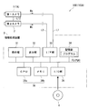
- FIG. 1 is a diagram illustrating a configuration example of a distance measuring device according to an embodiment and a modification.
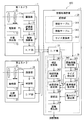
- FIG. 2 is a block diagram illustrating a functional configuration of the distance measuring device according to the embodiment.
- FIG. 3 is a diagram illustrating an area in which an evaluation value is calculated in one image.
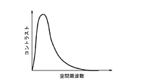
- FIG. 4 is a graph illustrating the relationship between the spatial frequency and contrast according to MTF.
- FIG. 5 is a diagram illustrating an example of how the reference points are set for the reference image.
- FIG. 6 is a diagram illustrating an example of how the reference area is set for the reference image.
- FIG. 7 is a diagram illustrating an example of how the reference area is set for the reference image.
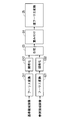
- FIG. 8 is a diagram illustrating a calculation flow in the corresponding point search processing according to the embodiment.
- FIG. 1 is a diagram illustrating a configuration example of a distance measuring device according to an embodiment and a modification.
- FIG. 2 is a block diagram illustrating a functional configuration of the distance measuring
- FIG. 9 is a diagram illustrating a distribution of POC values.
- FIG. 10 is a flowchart illustrating a flow of a distance measurement operation according to an embodiment.
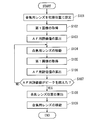
- FIG. 11 is a flowchart illustrating the operation flow of the focusing operation.
- FIG. 12 is a block diagram illustrating a functional configuration of a distance measuring device according to a modification.
- FIG. 13 is a diagram illustrating an example of how the reference area is set for the reference image.
- FIG. 14 is a diagram illustrating an example of how the reference area is set for the reference image.
- FIG. 15 is a flowchart illustrating a flow of a distance measurement operation according to a modification.
- FIG. 1 is a diagram illustrating a schematic configuration of a distance measuring device 100 according to an embodiment.
- the distance measuring device 100 includes a first camera 1, a second camera 2, and an information processing device 3.
- the first camera 1 and the second camera 2 are connected via a communication line L12 so that data transmission is possible.
- the first camera 1 is connected to the information processing device 3 via the communication line L1 so as to be able to transmit data
- the second camera 2 is connected to be able to transmit data to the information processing device 3 via the communication line L2.
- the communication lines L1, L2, and L12 may be any of a wired line and a wireless line.
- the first and second cameras 1 and 2 are imaging devices that respectively acquire images by imaging a subject. These first and second cameras 1 and 2 are arranged side by side in one direction.
- the one direction may be, for example, the horizontal direction.
- the optical axis of the imaging lens of the first camera 1 and the optical axis of the imaging lens of the second camera 2 are spaced apart in the horizontal direction.
- the distance between the optical axis of the imaging lens of the first camera 1 and the optical axis of the imaging lens of the second camera 2 is the base line length related to the first and second cameras 1 and 2.
- the first and second cameras 1 and 2 image, for example, a subject located in front of the camera from different viewpoints at the same timing.
- the two images captured at the same timing by the first and second cameras 1 and 2 are so-called stereo images. That is, the stereo image includes an image (also referred to as a first image) acquired by imaging with the first camera 1 and an image (also referred to as a second image) acquired by imaging with the second camera 2.
- the data Ma relating to the first image and the data Mb relating to the second image can be transmitted from the first and second cameras 1 and 2 to the information processing device 3 via the communication lines L1 and L2.
- the information processing apparatus 3 may be a personal computer (personal computer), for example, and includes an operation unit 31, a display unit 32, an interface (I / F) unit 33, a storage unit 34, an input / output (I / O) unit 35, and A control unit 36 is provided.
- personal computer personal computer
- the operation unit 31 includes, for example, a mouse and a keyboard.
- the display unit 32 includes, for example, a liquid crystal display.
- the I / F unit 33 exchanges data between the first and second cameras 1 and 2 and the information processing apparatus 3.
- the storage unit 34 includes, for example, a hard disk and stores the program PG and various data.
- the I / O unit 35 includes, for example, a disk drive, receives the storage medium 4 such as an optical disk, and exchanges data between the storage medium 4 and the control unit 36.
- the control unit 36 includes, for example, a CPU 36a that functions as a processor, a memory 36b that temporarily stores information, and the like. The control unit 36 implements various functions and information processing by reading and executing the program PG in the storage unit 34.
- the aberrations of the first and second cameras 1 and 2 are corrected well, and the first and second cameras 1 and 2 are substantially parallel (preferably Is completely parallel). That is, the optical axes of the first and second cameras 1 and 2 are set to be substantially parallel (preferably completely parallel), and the subject captured in the first and second images is located at the outer edge of the first and second images. In contrast, they have substantially the same angular relationship (preferably completely the same angular relationship). However, if the actual first and second cameras 1 and 2 are not in such a condition, they may be converted into a stereo image that is regarded as being captured under the same condition by image processing.
- FIG. 2 is a block diagram illustrating a functional configuration of a main part of the distance measuring apparatus 100 according to the present embodiment.
- FIG. 2 shows a functional configuration related to an operation for measuring the distance from the first and second cameras 1 and 2 to the subject (also referred to as a distance measurement operation).
- the first camera 1 as the first imaging device includes an optical system 11, a drive unit 12, a position detection unit 13, an imaging unit 14, an evaluation value calculation unit 15, a control calculation unit 16, and an interface (I / F) unit 17. I have.
- the optical system 11 includes, for example, a plurality of optical lenses.
- the plurality of optical lenses are optical members formed of glass or plastics.
- the plurality of optical lenses include one or more optical lenses as movable parts that are movable in the optical axis direction of the optical system 11 with respect to the main body of the first camera 1. Then, one or more optical lenses (also referred to as focusing lenses) 11 a serving as a movable unit can be focused on the subject by moving with the driving force of the driving unit 12.
- the drive unit 12 may be an actuator using a piezoelectric element or the like, for example.
- the drive unit 12 generates a driving force in accordance with a control signal from the control calculation unit 16, and moves the focusing lens 11a in the optical axis direction.
- AF adjustment automatic focus adjustment
- the focusing lens 11a is sequentially arranged at a plurality of focusing positions (also referred to as AF positions) by the drive unit 12. The Thereby, the position of the focusing lens 11a when the first camera 1 focuses on the subject is detected.
- the plurality of AF positions include, for example, positions where the focusing lens 11a has moved by a predetermined distance from the initial position in the movable range of the focusing lens 11a toward one direction.
- the initial position may be, for example, one end of the movable range of the focusing lens 11a
- one direction may be, for example, a direction from one end of the movable range of the focusing lens 11a to the other end. .
- the position detector 13 may be an electromagnetic sensor, for example.
- the position detector 13 detects the position of the focusing lens 11a in the optical axis direction within the movable range of the focusing lens 11a.
- Information indicating the position of the focusing lens 11 a detected by the position detection unit 13 (also referred to as position information) is sent to the control calculation unit 16.
- the imaging unit 14 includes, for example, an imaging element such as a CCD.
- the imaging unit 14 receives light from the subject via the optical system 11 and captures the subject to acquire a first image capturing the subject.
- the imaging unit 14 when the AF adjustment is performed in the first camera 1, the imaging unit 14 has the subject in each state in which the focusing lens 11 a is sequentially arranged at a plurality of AF positions by the driving unit 12. To obtain a plurality of AF adjustment images (also referred to as AF images).
- the imaging unit 14 captures an image of the subject by capturing the subject in a state where the first camera 1 is focused on the subject (also referred to as a focused state) (first focused image). (Also called).
- the first image data including the AF image and the first focused image acquired by the imaging unit 14 is sent to the evaluation value calculation unit 15 and the control calculation unit 16.
- the evaluation value calculation unit 15 may be configured by, for example, a dedicated electronic circuit, or may be functionally realized by executing software with a processor.
- the evaluation value calculator 15 uses the first image data to calculate an evaluation value indicating the degree of focus of the first camera 1 on the subject (also referred to as the degree of focus).
- the evaluation value may be, for example, a value indicating contrast (also referred to as a contrast value).
- a contrast value for example, a high frequency component of the data of the first image is extracted by a digital filter functioning as a high pass filter, a detection circuit, and an integration circuit, and the positive and negative components of the signal of the high frequency component are aligned in the same direction and integrated. Can be calculated.
- evaluation values are calculated for each of a predetermined number of regions included in the first image G1.
- the predetermined number is set to 9
- evaluation values are respectively calculated for the first to ninth image regions A1 to A9 near the center of the first image G1.
- the evaluation value calculation unit 15 calculates evaluation values for each of the image areas A1 to A9 based on the data of each AF image.
- the evaluation value calculation unit 15 performs an AF adjustment evaluation value (AF evaluation value) according to a predetermined rule from a plurality of evaluation values for the first to ninth image regions A1 to A9 for each AF image data.
- AF evaluation value AF evaluation value
- the predetermined rule may be a rule for calculating an average value of a plurality of evaluation values for the first to ninth image regions A1 to A9, for example.
- the evaluation value calculation unit 15 uses the data of the first focused image to calculate evaluation values (also referred to as evaluation values at the time of focusing) for each of the image areas A1 to A9 included in the first focused image. calculate.
- the control arithmetic unit 16 may be configured by, for example, a dedicated electronic circuit, or may be functionally realized by executing software on a processor.
- the control calculation unit 16 as a focusing control unit performs a so-called hill-climbing AF adjustment. Specifically, when AF adjustment is performed, the control calculation unit 16 moves the focusing lens 11 a based on the plurality of AF evaluation values calculated by the evaluation value calculation unit 15, so that the first The camera 1 is set to an in-focus state.
- the control calculation unit 16 acquires the position information of the focusing lens 11a from the position detection unit 13, and moves the focusing lens 11a to move the focusing lens 11a to a plurality of AF positions. Move sequentially. At this time, the control calculation unit 16 acquires the AF evaluation value from the evaluation value calculation unit 15 when the focusing lens 11a is moved to each AF position, so that the AF evaluation value is obtained for each position information. To get.
- each AF evaluation value is a contrast value
- the control calculation unit 16 calculates the position of the focusing lens 11a corresponding to the peak of the contrast value (also referred to as a focusing lens position). .
- the first camera 1 can be set to the in-focus state by moving the focusing lens 11 a to the focusing lens position under the control of the control calculation unit 16.
- the control calculation unit 16 determines whether each of the first to ninth image areas A1 to A9 is in the front focus state or the rear focus state. Is performed (also referred to as a focus state determination process).
- the front focus state refers to a state in which the focus of the first camera 1 is in the foreground than the subject
- the rear focus state refers to a state in which the focus of the first camera 1 is in the distance from the subject.
- the control calculation unit 16 for example, when AF adjustment is performed, the first to ninth image regions A1 to A9 of the AF image acquired in each state where the focusing lens 11a is disposed at each AF position. Based on the evaluation values calculated for each of the first to ninth image regions A1 to A9 when the first camera 1 is in focus, the respective focus state determination processing is performed.
- control calculation unit 16 receives data indicating the evaluation values at the time of focusing on the first to ninth image regions A1 to A9 from the evaluation value calculation unit 15, and receives data of the first focused image from the imaging unit 14. . Then, the control calculation unit 16 includes data indicating evaluation values at the time of focusing on the first to ninth image areas A1 to A9, information indicating the determination result of the focus state determination process (also referred to as pre-focus information), and first information
- the focused image data is sent to the information processing apparatus 3 via the I / F unit 17.
- control calculation unit 16 sends information on the focusing lens position (also referred to as focusing position information) to the second camera 2 and the information processing device 3 via the I / F unit 17.
- the second camera 2 as the second imaging device includes an optical system 21, a drive unit 22, a position detection unit 23, an imaging unit 24, a control unit 26, and an interface (I / F) unit 27.
- the optical system 21 has a configuration similar to that of the optical system 11, for example. Specifically, in the optical system 21, one or more optical lenses (focusing lenses) 21 a serving as a movable unit can be focused on the subject by moving with the driving force of the driving unit 22.
- the drive unit 22 may be an actuator using a piezoelectric element or the like, for example, similarly to the drive unit 12.
- the driving unit 22 generates a driving force according to a control signal from the control unit 26, and moves the focusing lens 21a in the optical axis direction.
- the position detection unit 23 may be an electromagnetic sensor or the like, for example, similarly to the position detection unit 13.
- the position detector 23 detects the position of the focusing lens 21a in the optical axis direction within the movable range of the focusing lens 21a.
- Information (position information) indicating the position of the focusing lens 21 a detected by the position detection unit 23 is sent to the control unit 26.
- the imaging unit 24 includes an imaging element such as a CCD, for example, similarly to the imaging unit 14.
- the imaging unit 24 receives light from the subject via the optical system 21 and captures the subject, thereby acquiring a second image capturing the subject.
- the imaging unit 24 captures an image of the subject in the in-focus state in which the second camera 2 is in focus on the subject (also referred to as a second focused image). Say) to get. Note that the data of the second focused image acquired by the imaging unit 24 is sent to the control unit 26.
- the control unit 26 may be configured by, for example, a dedicated electronic circuit, or may be functionally realized by executing software by a processor.
- the control unit 26 acquires in-focus position information from the first camera 1 via the I / F unit 27. Then, the control unit 26 controls the driving unit 22 while referring to the position information obtained from the position detection unit 23, and focuses the focusing lens 21 a according to the focusing position information of the first camera 1. Move to the lens position. Thereby, the 2nd camera 2 can be set to an in-focus state.
- control unit 26 receives the data of the second focused image from the imaging unit 24. Then, the control unit 26 sends the data of the second focused image to the information processing device 3 via the I / F unit 27.
- the information processing apparatus 3 includes the I / F unit 33, the storage unit 34, and the control unit 36.
- the I / F unit 33 functions as a portion (also referred to as an information acquisition unit) that acquires information from the first and second cameras 1 and 2.
- the I / F unit 33 includes data of the first focused image, data indicating evaluation values at the time of focusing on the first to ninth image areas A1 to A9, information before and after focusing, and focusing position information. Obtained from the first camera 1 and data of the second focused image is obtained from the second camera 2. Then, the I / F unit 33 includes data on the first and second focused images, data indicating the evaluation values at the time of focusing on the first to ninth image areas A1 to A9 input from the first camera 1, focus, The front-rear information and the in-focus position information are sent to the control unit 36.
- the storage unit 34 stores, for example, a parallax table 341, a function table 342, and a size conversion formula 343.
- the parallax table 341 is a table in which the relationship between the focusing information related to the focusing of the first camera 1 and the parallax is described.
- the focus information is, for example, a combination of focus position information about the first camera 1, data indicating evaluation values at the time of focusing on the first to ninth image areas A1 to A9, and information before and after focusing. Any information may be used.
- the parallax corresponds to a shift amount of a position where the same portion of the subject is captured between the first focused image and the second focused image.
- the parallax table 341 can be obtained in advance by, for example, an optical simulation using optical design values of the first and second cameras 1 and 2.
- the parallax table 341 can be obtained in advance by experiments, for example. In the experiment, for example, when the positional relationship between the first and second cameras 1 and 2 and the subject is known, the information on the parallax table 341 can be obtained by actually obtaining the focusing information.
- the function table 342 is a table indicating MTF (Modulation Transfer Function) included in the spatial transfer function.
- the MTF is one of the indexes for evaluating the lens performance.
- the MTF expresses how faithfully the contrast of the subject can be reproduced as a spatial frequency characteristic.
- the horizontal axis represents spatial frequency and the vertical axis represents contrast.
- the higher the contrast of the low frequency left side of the graph in FIG. 4
- the higher the high frequency right side of the graph in FIG. 4
- the function table 342 information indicating the MTF is described for each evaluation value at the time of focusing. That is, the function table 342 describes information (also referred to as relationship information) indicating the relationship between the evaluation value at the time of focusing and the MTF as the optical transfer function information related to the optical systems 11 and 21.
- the function table 342 can be obtained in advance, for example, by optical simulation using optical design values of the first and second cameras 1 and 2.
- the size conversion equation 343 is an equation for converting the cutoff frequency of the MTF into the size of a window (also referred to as a search window) that defines the search range of corresponding points.
- the cutoff frequency of the MTF refers to a spatial frequency that is lower than a predetermined contrast in the MTF as shown in FIG. 4 in which the contrast decreases as the spatial frequency increases.
- the cutoff frequency is f
- the predetermined constant is k
- the length of one side of the square search window is L
- the unit of the cutoff frequency is (1 / pixel). If the maximum contrast value (also referred to as the maximum contrast value) is 1, the predetermined contrast may be a value obtained by multiplying the maximum contrast value by a predetermined number, for example. The predetermined value may be any of 0.5, 0.6, and 0.8, for example.
- the size conversion formula 343 may be a table in which information in which the cutoff frequency of the MTF is associated with the size of the search window is described.
- the control unit 36 includes, as functional configurations, a parallax conversion unit 361, an initial parallax determination unit 362, a function information identification unit 363, a size setting unit 364, a reference region setting unit 365, a reference region setting unit 366, a weighting setting unit 367, A search unit 368 and a distance calculation unit 369 are provided.
- the parallax conversion unit 361 converts the focusing information into parallax according to the parallax table 341.
- parallax corresponding to the focusing information obtained from the first camera 1 is recognized from the parallax table 341.
- the initial parallax determination unit 362 searches for corresponding points between the first focused image G1 and the second focused image G2 based on the parallax recognized by the parallax conversion unit 361 for each of the image regions A1 to A9.
- An initial value of parallax in the process (also referred to as initial parallax) is determined.
- the first focused image G1 is used as a reference image (also referred to as a reference image) when searching for corresponding points.
- a reference image also referred to as a reference image
- a pixel (also referred to as a reference point) Sp1 is set as a reference when searching for.
- the reference point Sp1 for example, an upper left pixel of the reference image G1 is set first, and all pixels included in the reference image G1 are sequentially set.
- the parallax obtained in 361 is determined as the initial parallax related to the reference point Sp1. That is, the initial parallax is determined in consideration of not only the in-focus position of the first camera 1 but also information before and after focusing on each of the first to ninth image areas A1 to A9.
- the minimum value or the maximum value of the parallax obtained in 361 may be determined as the initial parallax.
- the parallax conversion unit 361 for the image region closest to the reference point Sp1 among the first to ninth image regions A1 to A9. Is determined as the initial parallax for the reference point Sp1.
- the function information specifying unit 363 specifies the MTF as information of the optical transfer function corresponding to the evaluation value at the time of focusing from the function table 342.
- the MTF also referred to as a representative MTF
- the representative value of the evaluation value may be an average value of the evaluation values at the time of focusing on the first to ninth image regions A1 to A9, or may be an average value of the top N pieces. good.
- the function information specifying unit 363 may specify the nth MTF corresponding to the evaluation value at the time of focusing for each nth image region An (n is an integer of 1 to 9).
- the size setting unit 364 sets the size of the search window according to the MTF specified by the function information specifying unit 363.
- the search window includes a reference area set by the reference area setting unit 365 and a reference area set by the reference area setting unit 366.
- the size of the search window can be set based on the cutoff frequency of the representative MTF and the size conversion formula 343. Thereby, the amount of information that can be deficient in accordance with the MTF is ensured by setting the size of the search window in accordance with the MTF, and the search accuracy of the corresponding points can be maintained.
- the size setting unit 364 may set the size of the search window for each image area An based on the cutoff frequency of the nth MTF and the size conversion equation 343 described above. For example, when the reference point Sp1 is included in the nth image region An, the nth image region An is determined based on the cutoff frequency of the nth MTF specified for the nth image region An and the size conversion equation 343. The size of the search window can be set. Further, for example, when the reference point Sp1 is located in the vicinity of the boundary between the first to ninth image areas A1 to A9, the MTF specified for a plurality of image areas in contact with the boundary among the first to ninth image areas A1 to A9.
- the size of the search window can be set based on the cut-off frequency and the size conversion formula 343.
- the size of the search window can be set based on the minimum value or the maximum value among the cutoff frequencies of the MTF specified for a plurality of image regions in contact with the boundary and the size conversion formula 343. For example, when the reference point Sp1 is not included in the first to ninth image regions A1 to A9, the nth image region An closest to the reference point Sp1 among the first to ninth image regions A1 to A9 is specified.
- the size of the search window can be set based on the cut-off frequency of the MTF and the size conversion equation 343.
- the reference area setting unit 365 sets a reference search window (also referred to as a reference area) in the reference image G1. Specifically, as shown in FIG. 6, a reference area W1 including the reference point Sp1 is set with the reference point Sp1 as a reference.
- the size of the reference area W ⁇ b> 1 only needs to be set by the size setting unit 364.
- the reference region W1 may be set with the reference point Sp1 as the center, for example. In this case, the reference area W1 is defined by the reference point Sp1.
- the reference area setting unit 366 uses the second focused image G2 as the other image (also referred to as a reference image) that is referred to when searching for corresponding points, and a search window (also referred to as a reference area) that defines a reference target for the reference image G2.
- a search window also referred to as a reference area
- a pixel also referred to as a reference point
- Pp ⁇ b> 1 that serves as a reference reference when searching for a corresponding point
- a reference area W2 including the reference point Pp1 is set based on the reference point Pp1.
- the amount of deviation between the position of the reference point Pp1 in the reference image G2 and the position of the reference point Sp1 in the reference image G1 is set based on the initial disparity determined by the initial disparity determining unit 362. For example, the amount of deviation and the initial parallax need only match.
- the size of the reference area W2 may be set by the size setting unit 364 in the same manner as the size of the standard area W1.
- the reference region W2 may be set around the reference point Pp1, for example. In this case, the reference area W2 is defined by the reference point Pp1.
- the reference area W2 is a range (also referred to as a search range) in which the search unit 368 searches for the corresponding point corresponding to the reference point Sp1 in the reference image G2. Therefore, the search range is determined by the parallax conversion unit 361, the initial parallax determination unit 362, the size setting unit 364, and the reference region setting unit 366 based on the focusing information. That is, the parallax conversion unit 361, the initial parallax determination unit 362, the size setting unit 364, and the reference region setting unit 366 function as a part (also referred to as a search range determination unit) 360 that determines a search range.
- the search range when the corresponding point of each reference point Sp1 is searched by the initial parallax determining unit 362 is one or more having a predetermined positional relationship with each reference point Sp1 in the first to ninth image regions A1 to A9. It can be determined based on the evaluation value at the time of focusing on the image area and focusing position information.
- the predetermined positional relationship may be, for example, a positional relationship closest to the reference point Sp1 in the first to ninth image regions A1 to A9.
- the weight setting unit 367 sets a weighting coefficient for each spatial frequency in accordance with the MTF specified by the function information specifying unit 363.
- a weighting coefficient is set for each spatial frequency in accordance with the MTF specified for one or more image regions having a predetermined positional relationship with each reference point Sp1 in the first to ninth image regions A1 to A9.
- the predetermined positional relationship may be, for example, the positional relationship including the reference point Sp1 in the first to ninth image regions A1 to A9 or the closest positional relationship.
- the contrast of each spatial frequency in the MTF can be set as a weighting coefficient of the corresponding spatial frequency.
- the search unit 368 searches the reference image G2 for a corresponding point corresponding to the reference point Sp1 in the reference image G1.
- the search unit 368 uses a phase-only correlation (POC) calculation method, and corresponds to the reference point Sp1 based on the frequency component related to the region image included in the reference region W1 and the frequency component related to the reference region W2. Corresponding points are searched. Thereby, the information processing apparatus 3 works as a corresponding point search apparatus.
- weighting is performed for each frequency using the weighting coefficient for each frequency set by the weighting setting unit 367 in the corresponding point search processing.
- the influence on the search result is reduced by the calculation related to the spatial frequency in which the contrast is low in the MTF.
- the corresponding point search accuracy can be improved by improving the S / N ratio, and the corresponding point search speed can be increased by reducing the calculation amount.
- a weighting coefficient is set for each spatial frequency in accordance with the MTF specified for one or more image areas having a predetermined positional relationship with each reference point Sp1 in the first to ninth image areas A1 to A9.
- the corresponding point search process is further optimized. That is, it is not uniform, and for each region where the reference point Sp1 is located, it is possible to improve the corresponding point search accuracy by improving the S / N ratio and to speed up the corresponding point search by reducing the calculation amount.
- the corresponding point search process using the POC calculation method in the search unit 368 will be described.
- correlation calculation is performed to obtain a numerical value indicating the degree of correlation (similarity) between images using a phase component signal in which the amplitude component is suppressed among the frequency resolved signals of the image pattern.
- FIG. 8 is a diagram for explaining the corresponding point search processing using the POC calculation method.
- the reference area W1 and the reference region W2 is the pixel a predetermined number N 1 in the X direction, each array of pixels of the predetermined number N 2 along the Y direction is treated as an image area to be arranged.
- These image areas are expressed by the following equation (1).
- f (n 1 , n 2 ) in the above equation 1 indicates a region image (also referred to as a reference region image) included in the reference region W1
- g (n 1 , n 2 ) in the above equation 1 is , A region image (also referred to as a reference region image) included in the reference region W2.
- N 1 and N 2 are substituted for the subscript P of W in the proviso of the above formula 2, and 1 and 2 are substituted for the subscript s of k. Note that (k 1 , k 2 ) indicates a two-dimensional spatial frequency.
- Equation 4 Wt (k 1 , k 2 ) expressed by Equation 4 is a weighting coefficient corresponding to the spatial frequency (k 1 , k 2 ) set by the weight setting unit 367. That is, the weighting process C4 using the arithmetic expression expressed by Equation 4 is performed.
- Equation 5 a two-dimensional inverse Fourier transform process C5 is performed using the arithmetic expression shown in Equation 5. Thereby, the correlation calculation between the images is performed, and the result (POC value) is output.
- a calculation result (POC value) indicating the correlation between the reference region image related to the reference region W1 and the reference region image related to the reference region W2 is obtained.
- a result (POC value) as shown in FIG. ) Is obtained.
- the POC value is obtained discretely. For this reason, if an interpolation operation is performed between adjacent pixels and the position of the peak Jc is estimated with a subpixel size smaller than the size of one pixel, the corresponding points can be detected more finely.
- a method of the interpolation calculation a method in which a parabola function is obtained from the distribution of the POC values obtained discretely can be considered.
- the search unit 368 determines the position of the corresponding point in the reference image G2, the position of the reference point Sp1 in the reference image G1, and the position of the corresponding point in the reference image G2. Is detected (also referred to as parallax).
- the distance calculation unit 369 calculates the distance from the first and second cameras 1 and 2 to the portion of the subject captured by the reference point Sp1 based on the search result by the search unit 368. Specifically, the distance is the amount of deviation between the position of the reference point Sp1 in the reference image G1 and the position of the corresponding point in the reference image G2, the internal parameters and the external parameters of the first and second cameras 1 and 2. Is calculated using triangulation techniques.
- the internal parameters include, for example, parameters indicating the focal lengths of the optical systems 11 and 21, the image centers, the inclinations of the imaging units 14 and 24, and the like.
- the external parameters include, for example, parameters indicating the positional relationship and posture relationship between the first camera 1 and the second camera 2.
- FIG. 10 and FIG. 11 are flowcharts showing an example of a distance measurement operation flow in the distance measurement apparatus 100. This flow can be realized by the control of the control calculation unit 16, the control unit 26, and the control unit 36, for example.
- step S1 the first camera 1 performs an operation of focusing on the subject (also referred to as a focusing operation).
- the operation flow shown in FIG. 11 can be executed.
- the focusing lens 11a is set to the initial position under the control of the control calculation unit 16 (step S101).
- a first image is acquired by the imaging unit 14 (step S102).
- the evaluation value calculation unit 15 calculates the evaluation value for each of the first to ninth image areas A1 to A9 for the first image acquired in step S102, and the AF evaluation value is calculated based on the evaluation value (step S103). ).
- the focusing lens 11a moves in one direction by a predetermined distance under the control of the control calculation unit 16 (step S104).
- a first image is acquired by the imaging unit 14 (step S105).
- the evaluation value for each of the first to ninth image areas A1 to A9 is calculated by the evaluation value calculation unit 15 for the first image acquired in step S105, and the AF evaluation value is calculated based on the evaluation value (step S106).
- Step S107 the control calculation unit 16 determines whether or not the AF evaluation value exceeds the peak based on the AF evaluation value calculated in Step S103 and Step S106 (Step S107).
- the processing of steps S104 to S107 is repeated until the AF evaluation value exceeds the peak.
- the control calculation unit 16 calculates the focus lens position corresponding to the peak.
- in-focus position information indicating the in-focus lens position is transmitted from the control calculation unit 16 to the control unit 26 of the second camera 2 and the information processing apparatus 3.
- the focus lens 11a is moved to the focus lens position under the control of the control calculation unit 16 (step S109). Thereby, the focusing operation in step S1 is completed.
- the above is the so-called hill-climbing AF adjustment.
- step S2 the focusing operation of the second camera 2 is performed.
- the focusing lens 21 a is moved to the focusing lens position corresponding to the focusing position information of the first camera 1. Note that step S2 may be executed in parallel with step S109 described above.
- step S3 the first and second focused images G1, G2 are acquired by the first and second cameras 1, 2.
- step S4 the evaluation value calculation unit 15 calculates the evaluation value at the time of focusing for each of the image areas A1 to A9 of the first focused image G1 acquired in step S3.
- step S5 the control calculation unit 16 performs a focus state determination process.
- the first to ninth image areas are calculated based on the evaluation values calculated for the first to ninth image areas A1 to A9 of the respective AF images acquired in the operations of steps S103 and S106 of step S1. It can be determined whether each of the nine image areas A1 to A9 is in the front focus state or the rear focus state.
- step S6 the parallax conversion unit 361 converts the focusing information for each of the image areas A1 to A9 into parallax according to the parallax table 341.
- step S7 the initial parallax determining unit 362 sets the first focused image G1 acquired in step S3 as a reference image, and the reference point Sp1 is set in the reference image G1.
- step S8 the initial parallax determining unit 362 determines the initial parallax related to the reference point Sp1 set in step S7 based on the parallax obtained in step S6.
- Step S9 the MTF corresponding to the evaluation value at the time of focusing calculated in Step S4 is specified from the function table 342 by the function information specifying unit 363.
- step S10 the size setting unit 364 sets the size of the search window according to the MTF specified in step S9.
- step S11 the weighting setting unit 367 sets a weighting coefficient for each spatial frequency in accordance with the MTF specified in step S9.
- step S12 the reference area setting unit 365 uses the reference point Sp1 set in step S7 as a reference, and the reference area W1 corresponding to the size of the search window set in step S10 is set in the reference image G1.
- the reference area setting unit 366 sets the second focused image G2 as a reference image, and sets the reference area W2 in the reference image G2.
- the reference point Pp1 is set in the reference image G2 based on the position of the reference point Sp1 set in step S7 in the reference image G1 and the initial parallax determined in step S8. Then, the reference point Pp1 is used as a reference, and a reference area W2 corresponding to the size of the search window set in step S10 is set in the reference image G2.
- step S14 the search unit 368 searches the reference image G2 for a corresponding point corresponding to the reference point Sp1 in the reference image G1.
- the corresponding points are searched by the POC calculation method using the weighting coefficient set in step S11.
- the position of the corresponding point in the reference image G2 and the amount of deviation (also referred to as parallax) between the position of the reference point Sp1 in the reference image G1 and the position of the corresponding point in the reference image G2 are detected.
- step S15 the distance calculation unit 369 calculates the distance from the first and second cameras 1 and 2 to the portion of the subject captured at the reference point Sp1 based on the search result in step S14. At this time, information indicating the distance related to the reference point Sp1 is stored in the storage unit 34.
- step S16 the initial parallax determining unit 362 calculates the distance from the first and second cameras 1 and 2 to the subject captured at the reference point Sp1 in the reference image G1 (also referred to as a distance measurement point). Whether or not remains is determined. Here, if the distance measurement point remains, the process returns to step S7, and the processes of steps S7 to S16 are repeated until the distance measurement point remains. If there are no points to be measured, the operation flow ends.
- the corresponding points are based on the position information (focus position information) of the focusing lens 11a when the first camera 1 is in focus.
- the search range is determined.
- the fact that the approximate distance from the first camera 1 to the subject is known by the AF adjustment is used, and the search range of the corresponding points is narrowed down. For this reason, corresponding points can be searched for between the standard image G1 and the reference image G2 with high accuracy and high speed.
- the corresponding points can be searched between the plurality of images with high accuracy and at high speed. As a result, the distance from the first and second cameras 1 and 2 to the subject can be calculated with high accuracy and high speed. .
- the search range of the corresponding points is determined based on the evaluation value at the time of focusing indicating the degree of focus of the first camera 1 and the focus position information, so that the search range can be further optimized.
- an imaging device that performs hill-climbing AF adjustment can be employed as the first camera 1.
- an imaging device having a general-purpose AF adjustment function is used, and corresponding points can be searched between the standard image G1 and the reference image G2 with high accuracy and at high speed.
- the manufacturing cost and the size of the information processing device 3 and the distance measuring device 100 can be reduced.
- evaluation values at the time of focusing are calculated for the first to ninth image areas A1 to A9 of the reference image G1. Then, an evaluation value and information before and after focusing on one or more image areas having a predetermined positional relationship with the reference point Sp1 in the first to ninth image areas A1 to A9, and for focusing at the time of focusing
- the search range of the corresponding points is determined based on the position information of the lens 11a. As a result, the search range can be determined more appropriately for each region where the reference point is located, rather than being uniform. As a result, the amount of information used for calculation of the corresponding point search process is ensured for each region, and the corresponding point search accuracy can be appropriately maintained.
- the corresponding point search process weighting is performed for each frequency according to the MTF specified from the focusing information of the first camera 1.
- the frequency components included in the search range for the corresponding points can be roughly understood by the MTF specified based on the focusing information. Therefore, in the corresponding point search process, weighting is performed for each frequency according to the MTF.
- the corresponding point search accuracy can be improved by improving the S / N ratio, and the corresponding point search speed can be increased by reducing the calculation amount. That is, it is possible to improve the robustness and speed up in the corresponding point search process.
- the focusing information on the first camera 1 and the evaluation values at the time of focusing on the first to ninth image areas A1 to A9 are included in the focusing information on the first camera 1.
- the information indicating the combination of the data to be displayed and the information before and after the focus is included, but is not limited thereto.
- the focusing information related to the first camera 1 may not include at least one of the evaluation value at the time of focusing on the first to ninth image areas A1 to A9 and the information before and after focusing.
- at least one of the setting of the search window size according to the MTF and the weighting for each frequency according to the MTF may not be performed.
- the corresponding point search process using another calculation such as the SAD calculation method may be performed.
- the device 100A will be described.
- FIG. 12 is a block diagram showing a functional configuration of a distance measuring apparatus 100A according to a modification.
- FIG. 12 shows a functional configuration relating to a distance measuring operation for measuring the distance from the first and second cameras 1A, 2 to the subject.
- a distance measuring device 100A according to a modification is a function realized by the first camera 1, the program PG and information stored in the storage unit 34, and the control unit 36 in the distance measuring device 100 according to the one embodiment.
- the general structure has been changed.
- the first camera 1 is replaced with a first camera 1A including an evaluation value calculation unit 15A and a control calculation unit 16A instead of the evaluation value calculation unit 15 and the control calculation unit 16.
- the storage unit 34 stores the program PGA instead of the program PG, does not store the function table 342 and the size conversion formula 343, and stores the parallax table 341A instead of the parallax table 341.
- the search range determination unit 360 is changed to a search range determination unit 360A including a parallax conversion unit 361A, a standard parallax determination unit 362A, an upper limit parallax setting unit 370A, and a reference collation range setting unit 366A.
- the reference region setting unit 365 and the search unit 368 are changed to a reference region setting unit 365A and a search unit 368A.
- the evaluation value calculation unit 15A compares the evaluation value calculation unit 15 according to the above-described embodiment with the first camera for the subject for the entire image region including the first to ninth image regions A1 to A9 shown in FIG. The difference is that an evaluation value indicating the degree of focus of 1A is calculated.
- the control calculation unit 16A as the focus control unit performs a so-called hill-climbing AF adjustment in the same manner as the control calculation unit 16 according to the above-described embodiment.
- the control calculation unit 16A does not perform the focus state determination process, and does not receive data indicating the evaluation value at the time of focusing for each of the first to ninth image areas A1 to A9 from the evaluation value calculation unit 15A. It differs from the control calculation part 16 which concerns on embodiment.
- the focus information related to the first camera 1A sent to the information processing apparatus 3 by the control calculation unit 16A includes the evaluation value at the time of focusing and the information before and after focusing on the first to ninth image areas A1 to A9. In-focus position information is included.
- the parallax table 341A is a table in which the relationship between the focusing information and the parallax related to the first camera 1A is described, similarly to the parallax table 341 according to the above-described embodiment.
- the focusing information of the parallax table 341A does not include the evaluation value at the time of focusing on the first to ninth image areas A1 to A9 and the information before and after focusing, and it is sufficient that the focusing position information is included.
- the parallax table 341A can be obtained in advance, for example, by optical simulation or experiment using optical design values of the first and second cameras 1A, 2 in the same manner as the parallax table 341 according to the above-described embodiment.
- the parallax conversion unit 361A converts in-focus position information as in-focus information related to the first camera 1A into parallax according to the parallax table 341A.
- the parallax corresponding to the in-focus position information related to the first camera 1A is recognized from the parallax table 341A.
- the standard parallax determination unit 362A uses standard parallax (standard parallax) for the corresponding point search processing between the first focused image G1 and the second focused image G2. (Also called).
- standard parallax standard parallax
- the first focused image G1 is set as a reference image, and as shown in FIG. 13, the reference point Sp1 is set in the reference image G1, and the parallax recognized by the parallax conversion unit 361A
- the standard parallax can be determined. Thereby, the standard parallax can be determined without adding another function to the imaging apparatus having a general-purpose AF adjustment function. As a result, the manufacturing cost and size of the first camera 1A and the distance measuring device 100A can be reduced.
- the upper limit parallax setting unit 370A sets an upper limit of parallax (also referred to as upper limit parallax) that defines the scanning range of the search window in the corresponding point search process using the SAD calculation method.
- the upper limit parallax may be, for example, a value obtained by adding a predetermined room to the standard parallax set by the standard parallax determination unit 362A.
- the predetermined margin may be a fixed value such as a predetermined number of pixels, or may be a value that increases in proportion to the standard parallax obtained by multiplying the standard parallax by a predetermined value.
- the reference area setting unit 365A sets a reference search window (also referred to as a reference area) W1A for the reference image G1.
- a reference area W1A that includes the reference point Sp1 is set with the reference point Sp1 as a reference.
- the reference region W1A for example, along the X direction is the pixel array of a predetermined number N 1, it may be any image region pixel of the predetermined number N 2 is arranged along the Y direction.
- the reference area W1A is defined by the reference point Sp1, and may be set around the reference point Sp1, for example.
- the reference collation range setting unit 366A uses the second focused image G2 as a reference image, and in the reference image G2, sets a setting range of a region image to be collated with the standard region image included in the standard region W1A. Specifically, the size of the reference area W2A having the same size as the standard area W1A is set, and one end Ps and the other end Pe of a range where the reference point Pp1 defining the reference area W2A is set in the reference image G2 are set.
- the direction in which the reference region W2A is scanned in the reference image G2 is a direction corresponding to the direction in which the optical axis of the imaging lens of the first camera 1A and the optical axis of the imaging lens of the second camera 2 are separated from each other.
- the X direction may correspond to the horizontal direction.
- one end Ps of a range in which the reference area W2A is scanned in the reference image G2 is set based on, for example, an upper limit parallax.
- the one end Ps is provided so that, for example, the amount of deviation between the position of the one end Ps in the reference image G2 and the position of the reference point Sp1 in the reference image G1 matches the upper limit parallax.
- the other end Pe is provided so that, for example, the position of the other end Pe in the reference image G2 matches the position of the reference point Sp1 in the reference image G1, that is, the parallax is 0 (zero).
- a range in which the reference region W2A is set in the reference image G2 is determined. That is, a range in which the reference image G2 is scanned in the reference area W2A that is a search window is determined.
- the search range in which the corresponding point is searched for by the search unit 368A in the reference image G2 is determined based on the focus position information.
- the search unit 368A searches the reference image G2 for a corresponding point corresponding to the reference point Sp1 in the reference image G1, using the SAD calculation method. Thereby, the information processing apparatus 3 works as a corresponding point search apparatus.
- search unit 368A a corresponding point search process is performed based on the search range determined by search range determination unit 360A.
- the search unit 368A when one reference point Sp1 is set, as shown in FIG. 14, in the reference image G2, the reference point set while being shifted by a predetermined pixel from one end Ps to the other end Pe.
- a plurality of reference areas W2A are sequentially set based on Pp1.
- the predetermined pixel may be, for example, one pixel.
- the correlation between the region image (also referred to as a reference region image) related to the reference region W1A in the reference image G1 and the region image (also referred to as a reference region image) related to each reference region W2A in the reference image G2 is SAD. It is calculated by correlation calculation using a calculation method.
- the reference area image related to the reference area W2A having the highest degree of correlation with the reference area image related to the reference area W1A is detected, and the reference point Pp1 defining the reference area W2A is the corresponding point corresponding to the reference point Sp1. Detected.
- the search unit 368A detects the image data value (also referred to as a reference image data value) of each pixel constituting the reference area image related to the reference area W1A, and detects each pixel constituting the reference area image related to the reference area W2A.
- An image data value (also referred to as a reference image data value) is detected.
- the absolute value of the difference between the standard image data value and the reference image data value is calculated for each pixel occupying the same position between the standard region image and the reference region image. Further, all the absolute values of the differences calculated for each pixel are added. At this time, the smaller the value after the addition, the higher the degree of correlation. If the standard area image and the reference area image are substantially the same image, the correlation value approaches 0 as much as possible.
- FIG. 15 is a flowchart showing the flow of the distance measuring operation in the distance measuring apparatus 100A. This flow can be realized by the control of the control calculation unit 16A, the control unit 26, and the control unit 36, for example.
- step S21 a focusing operation is performed in the first camera 1 (step S21).
- step S21 for example, the operation flow shown in FIG. 11 can be executed.
- in-focus position information indicating the in-focus lens position is transmitted from the control calculation unit 16A to the control unit 26 of the second camera 2 and the information processing device 3, respectively.
- step S22 the focusing operation of the second camera 2 is performed.
- the focusing lens 21a is moved to the focusing lens position under the control of the control unit 26.
- step S23 the first and second focused images G1, G2 are acquired by the first and second cameras 1, 2.
- step S24 the parallax conversion unit 361A converts the in-focus position information as the in-focus information obtained in step S21 into parallax according to the parallax table 341A.
- step S25 the standard parallax determining unit 362A sets the first focused image G1 acquired in step S23 as a reference image, and sets the reference point Sp1 in the reference image G1.
- step S26 the standard parallax determining unit 362A determines the standard parallax related to the reference point Sp1 set in step S25 based on the parallax obtained in step S24.
- step S27 the upper limit parallax setting unit 370A sets the upper limit parallax that defines the scanning range of the search window in the corresponding point search process based on the parallax obtained in step S24.
- step S28 the reference area W1A based on the reference point Sp1 set in step S25 is set in the reference image G1 by the reference area setting unit 365A.
- step S29 the reference collation range setting unit 366A uses the second focused image G2 as a reference image, and in the reference image G2, the set range of the region image to be collated with the standard region image included in the standard region W1A is determined in step S27. Is set based on the upper limit parallax and the position where the parallax is 0 (zero). Thereby, the search range is determined.
- step S30 the search unit 368A searches the reference image G2 for a corresponding point corresponding to the reference point Sp1 in the reference image G1.
- the corresponding points are searched by the SAD calculation method.
- the position of the corresponding point in the reference image G2 and the amount of deviation (also referred to as parallax) between the position of the reference point Sp1 in the reference image G1 and the position of the corresponding point in the reference image G2 are detected.
- step S31 the distance calculation unit 369 calculates the distance from the first and second cameras 1A and 2 to the portion captured by the reference point Sp1 of the subject based on the search result in step S30. At this time, information indicating the distance related to the reference point Sp1 is stored in the storage unit 34.
- step S32 the standard parallax determining unit 362A calculates the distance from the first and second cameras 1A, 2 to the subject captured by the reference point Sp1 in the reference image G1 (also referred to as a distance measurement point). Whether or not remains is determined. Here, if the distance measurement point remains, the process returns to step S25, and the processes of steps S25 to S32 are repeated until the distance measurement point remains. If there are no points to be measured, the operation flow ends.
- the focusing lens 11a serves as a movable part that is movable in the optical axis direction, but is not limited thereto.
- the imaging unit 14 may serve as a movable unit that can move in the optical axis direction, or both the focusing lens 11a and the imaging unit 14 may be in the optical axis direction. You may play the role as a movable part which can move.
- the imaging unit 24 may serve as a movable unit that is movable in the optical axis direction, and both the focusing lens 21a and the imaging unit 24 are in the optical axis direction. You may play the role as a movable part which can move.
- the parallax conversion unit 361 converts the combination of the representative value related to the evaluation value at the time of focusing on the first to ninth image regions A1 to A9 and the focusing position information into parallax.
- the representative value related to the evaluation value at the time of focusing may be an average value of the evaluation values at the time of focusing on the first to ninth image regions A1 to A9, or may be a maximum value.
- the search range determination unit 360 the search range when searching for the corresponding point corresponding to each reference point Sp1 is the representative value related to the evaluation value at the time of focusing for the first to ninth image regions A1 to A9. And the in-focus position information.
- the representative value related to the evaluation value at the time of focusing is, for example, the evaluation at the time of focusing on one or more image areas having a predetermined positional relationship with the reference point Sp1 in the first to ninth image areas A1 to A9. You may obtain
- the predetermined positional relationship may be a positional relationship within a predetermined distance, for example.
- the initial parallax determining unit 362 determines the parallax representative values related to the first to ninth image regions A1 to A9 obtained by the parallax converting unit 361 as the initial parallax related to the reference point Sp1. May be.
- the representative value of the parallax may be an average value of parallax related to the first to ninth image regions A1 to A9, or may be a maximum value, or the top N (N is a natural number) It may be an average value.
- the average value, the maximum value, or the minimum value may be used as the initial parallax.
- interpolation using the parallax obtained by the parallax conversion unit 361 for one or more image areas having a predetermined positional relationship with the reference point Sp1 among the first to ninth image areas A1 to A9. Extrapolation, bilinear interpolation, and the like.
- the predetermined positional relationship may be, for example, a positional relationship within a predetermined distance.
- the minimum parallax value obtained by the parallax conversion unit 361 for one or more image areas having a predetermined positional relationship with the reference point Sp1 in the first to ninth image areas A1 to A9 is set as the initial parallax.
- the search range is determined as follows. For example, it is assumed that M image areas (M is an integer of 2 or more) of the first to ninth image areas A1 to A9 satisfy a predetermined positional relationship with the reference point Sp1. In this case, M disparity candidates between the reference point Sp1 in the reference image G1 and the corresponding points in the reference image G2 based on the evaluation value at the time of focusing on the M image regions and the focus position information. Is required.
- the search range is determined based on the smallest parallax candidate among the M parallax candidates. If such a configuration is adopted, it becomes difficult to set a search range greatly deviating from the corresponding points, so that the corresponding point search accuracy is stabilized.
- the weight setting unit 367 maintains high contrast up to the highest spatial frequency among the MTFs related to the first to ninth image regions A1 to A9 specified by the function information specifying unit 363.
- a weighting coefficient may be set for each frequency according to the MTF.
- a weighting coefficient may be set for each frequency in accordance with the MTF for which is maintained. If such a configuration is adopted, the balance between the improvement in the S / N ratio and the reduction in the amount of information used for computation can be adjusted. That is, the improvement of the search accuracy of the corresponding points by improving the S / N ratio and the speeding up of the search of the corresponding points by reducing the calculation amount can be made more appropriate.
- nine first to ninth image areas A1 to A9 are set as evaluation value calculation targets in the reference image G1, but the present invention is not limited to this.
- the image area as an evaluation value calculation target in the reference image G1 may be two or more. Further, there may be one image area as an evaluation value calculation target in the reference image G1.
- the initial parallax is determined by the parallax conversion unit 361 and the initial parallax determination unit 362 based on the data indicating the evaluation value at the time of focusing, the information before and after the focus, and the focus position information.
- the standard parallax is determined based on the in-focus position information by the parallax conversion unit 361A and the standard parallax determination unit 362A.
- the initial parallax or the standard parallax may be determined based on data indicating an evaluation value at the time of focusing and focusing position information.
- the parallax tables 341 and 341A may be tables that describe the relationship between the combination of the evaluation value at the time of focusing and the focusing position information and the parallax.
- the first focused image G1 is used as a reference image serving as a reference when searching for corresponding points, and the second focused image G2 searches for corresponding points.
- the present invention is not limited to this.
- the first focused image G1 is used as a reference image as the other image to which reference is made when searching for corresponding points
- the second focused image G2 is a reference image as one image that serves as a reference when searching for corresponding points. It may be said.
- the reference point Sp1 set in the reference image G2 is included in an image region corresponding to the first to ninth image regions A1 to A9 in the reference image G2, or the first to ninth image regions A1.
- Information such as whether or not the image area corresponding to .about.A9 has a predetermined positional relationship can be used in the calculation.
- AF adjustment is performed in the first cameras 1 and 1A, but is not limited thereto.
- a focusing operation in which the focus is adjusted by a manual operation may be executed.
- a third camera may be added.
- the image picked up by the third camera is used as the second reference image, and the corresponding point search process is performed based on the base image and the second reference image, as in the above-described one embodiment and one modification. It may be done. Then, the distance from the three cameras to the subject may be calculated based on the average value of the two parallaxes obtained for one reference point Sp1 by the corresponding point search process.
- the initial parallax (or the standard disparity)
- a shift amount (parallax) closer to (parallax) may be employed.
- the distance from the three cameras to the subject can be calculated based on the adopted amount of deviation (parallax).
- the third camera is arranged away from the first camera 1 (1A) in a direction different from the direction in which the first camera 1 (1A) and the second camera 2 are separated from each other.
- a fourth and subsequent cameras may be added. That is, two or more cameras may be provided. According to such a configuration, corresponding points can be searched for a plurality of images with high accuracy and at high speed.
- the focusing operation is performed in both the first camera 1 (1A) and the second camera 2, but the present invention is not limited to this.
- the second camera 2 may employ so-called pan focus in which the focus is fixed without performing the focusing operation.
- the POC calculation method is used in the corresponding point search process.
- the present invention is not limited to this, and for example, the rotation invariant phase-only correlation method (RIPOC: Rotation ⁇ ⁇ Invariant POC) may be used.
- the SAD calculation method is used in the corresponding point search process.
- the present invention is not limited to this.
- other methods such as SSD (Sum of Squared intensity Difference) calculation method and normalized cross-correlation An arithmetic method may be used.
- the search process for corresponding points between a set of images of the base image G1 and the reference image G2 is simply performed, but the present invention is not limited to this.
- a plurality of sets of images having different resolutions are generated for the base image G1 and the reference image G2 to have a hierarchical structure for each resolution, and between the images in each layer from the lower resolution upper layer to the higher resolution lower layer.
- a process in which the correlation calculation is sequentially performed may be executed for each reference point Sp1.
- the search range in the next hierarchy is based on the disparity obtained by performing the corresponding point search process similar to that in the above-described embodiment and the modified example for the lowest resolution upper layer. It should just be set.
- the distance calculation unit 369 is disposed inside the information processing device 3 that functions as a corresponding point search device, but is not limited thereto. .
- the distance calculation unit 369 may be arranged outside the information processing device 3 that functions as a corresponding point search device.
- the distance calculation unit 369 may be realized, for example, in another information processing apparatus connected to the information processing apparatus 3 so as to be able to transmit and receive data.
- the search range of the corresponding points is determined based on the position information from the movable part at the time of focusing of the imaging apparatus, but the present invention is not limited to this.
- the search range of the corresponding points may be determined based on the prediction information of the focus position from the imaging device at the time of focus.
Landscapes
- Engineering & Computer Science (AREA)
- Physics & Mathematics (AREA)
- Remote Sensing (AREA)
- Electromagnetism (AREA)
- General Physics & Mathematics (AREA)
- Radar, Positioning & Navigation (AREA)
- Multimedia (AREA)
- Signal Processing (AREA)
- Theoretical Computer Science (AREA)
- Computing Systems (AREA)
- Studio Devices (AREA)
- Automatic Focus Adjustment (AREA)
- Measurement Of Optical Distance (AREA)
- Image Processing (AREA)
- Length Measuring Devices By Optical Means (AREA)
Abstract
Description
図1は、一実施形態に係る距離測定装置100の概略構成を示す図である。距離測定装置100は、第1カメラ1と第2カメラ2と情報処理装置3とを備えている。
図2は、本実施形態に係る距離測定装置100の主要部の機能的な構成を示すブロック図である。図2では、第1および第2カメラ1,2から被写体までの距離を測定する動作(距離測定動作とも言う)に係る機能的な構成が示されている。
第1撮像装置としての第1カメラ1は、光学系11、駆動部12、位置検出部13、撮像部14、評価値算出部15、制御演算部16、およびインターフェース(I/F)部17を備えている。
第2撮像装置としての第2カメラ2は、光学系21、駆動部22、位置検出部23、撮像部24、制御部26、およびインターフェース(I/F)部27を備えている。
上述したように、情報処理装置3は、I/F部33、記憶部34、および制御部36を備えている。



図10および図11は、距離測定装置100における距離測定動作のフローの一例を示すフローチャートである。本フローは、例えば、制御演算部16、制御部26、および制御部36の制御によって実現され得る。
以上のように、一実施形態に係る対応点探索装置としての情報処理装置3では、第1カメラ1の合焦時における合焦用レンズ11aの位置情報(合焦位置情報)に基づいて対応点の探索範囲が決定される。ここでは、AF調節によって第1カメラ1から被写体までの大凡の距離が分かっていることが利用されて、対応点の探索範囲が絞られる。このため、基準画像G1と参照画像G2との間で高精度かつ高速に対応点が探索され得る。そして、距離測定装置100では、複数の画像の間で高精度かつ高速に対応点が探索され得る結果、第1および第2カメラ1,2から被写体までの距離が高精度かつ高速に算出され得る。
なお、本発明は上述の実施の形態に限定されるものではなく、本発明の要旨を逸脱しない範囲において種々の変更、改良等が可能である。
図12は、一変形例に係る距離測定装置100Aの機能的な構成を示すブロック図である。図12では、第1および第2カメラ1A,2から被写体までの距離を測定する距離測定動作に係る機能的な構成が示されている。
◎上記一実施形態および一変形例では、合焦用レンズ11aが光軸方向に移動可能である可動部としての役割を果たしたが、これに限られない。例えば、合焦用レンズ11aの代わりに、撮像部14が光軸方向に移動可能である可動部としての役割を果たしても良いし、合焦用レンズ11aおよび撮像部14の双方が光軸方向に移動可能である可動部としての役割を果たしても良い。また、合焦用レンズ21aの代わりに、撮像部24が光軸方向に移動可能である可動部としての役割を果たしても良いし、合焦用レンズ21aおよび撮像部24の双方が光軸方向に移動可能である可動部としての役割を果たしても良い。
2 第2カメラ
3 情報処理装置
100,100A 距離測定装置
11,21 光学系
11a,21a 合焦用レンズ
12,22 駆動部
13,23 位置検出部
14,24 撮像部
15,15A 評価値算出部
16,16A 制御演算部
26,36 制御部
34 記憶部
341,341A 視差テーブル
342 関数テーブル
343 サイズ変換式
360,360A 探索範囲決定部
361,361A 視差変換部
362 初期視差決定部
362A 標準視差決定部
363 関数情報特定部
364 サイズ設定部
365,365A 基準領域設定部
366 参照領域設定部
366A 参照照合範囲設定部
367 重み付け設定部
368,368A 探索部
369 距離算出部
370A 上限視差設定部
Claims (12)
- 光学系および撮像部のうちの少なくとも一方を含む可動部が移動して被写体に合焦している合焦状態にある第1撮像装置によって該被写体が撮像されて得られる第1画像、前記第1撮像装置とは異なる視点から第2撮像装置によって該被写体が撮像されて得られる第2画像、および前記第1撮像装置が前記合焦状態にある際における前記可動部の位置情報を取得する情報取得部と、
前記第1画像および前記第2画像のうちの一方画像と他方画像とについて、前記一方画像内の基準点に対応する対応点を前記他方画像において探索する探索部と、
前記他方画像のうちの前記探索部によって前記対応点が探索される探索範囲を、前記位置情報に基づいて決定する探索範囲決定部と、
を備えることを特徴とする対応点探索装置。 - 請求項1に記載の対応点探索装置であって、
前記第1撮像装置と、
前記第2撮像装置と、
を更に備えることを特徴とする対応点探索装置。 - 請求項1または請求項2に記載の対応点探索装置であって、
前記第1撮像装置が前記合焦状態にある際に前記撮像部によって得られる合焦画像のデータを用いて、該合焦画像内の1以上の画像領域について、前記第1撮像装置の前記被写体に対する合焦度合いを示す合焦時の評価値を算出する評価値算出部、
を更に備え、
前記探索範囲決定部が、
前記位置情報と前記合焦時の評価値とに基づいて、前記探索範囲を決定することを特徴とする対応点探索装置。 - 請求項3に記載の対応点探索装置であって、
前記評価値算出部が、
前記可動部が複数の位置に順次に配置されている各状態において前記撮像部によってそれぞれ得られる複数の画像のデータを用いて、前記第1撮像装置の前記被写体に対する合焦度合いを示す複数の評価値をそれぞれ算出し、
前記複数の評価値に基づいて前記可動部を移動させることで、前記第1撮像装置を前記合焦状態に設定する合焦制御部、
を更に備えることを特徴とする対応点探索装置。 - 請求項3または請求項4に記載の対応点探索装置であって、
前記合焦時の評価値と前記光学系に係る光学伝達関数の情報との関係を示す関係情報から、前記評価値算出部によって算出される前記合焦時の評価値に対応する光学伝達関数の情報を特定する関数情報特定部、
を更に備え、
前記探索部が、
前記一方画像のうちの前記基準点を包含する基準領域に係る周波数成分と、前記他方画像のうちの参照領域に係る周波数成分とに基づき、前記対応点を探索する探索処理を行い、該探索処理において、前記関数情報特定部で特定される前記光学伝達関数の情報に応じて、周波数毎に重み付けを施して演算を行い、
前記探索範囲が、
前記他方画像内の前記参照領域を含むことを特徴とする対応点探索装置。 - 請求項5に記載の対応点探索装置であって、
前記評価値算出部が、
前記合焦画像のデータを用いて、該合焦画像に含まれる複数の画像領域について、前記第1撮像装置の前記被写体に対する合焦度合いを示す合焦時の評価値をそれぞれ算出し、
前記関数情報特定部が、
前記関係情報から、各前記画像領域について前記評価値算出部によって算出される各前記合焦時の評価値にそれぞれ対応する光学伝達関数の情報を特定し、
前記探索部が、
前記探索処理において、前記複数の画像領域のうちの前記基準点と所定の位置関係を有する少なくとも1つの画像領域について前記関数情報特定部で特定される光学伝達関数の情報に応じて、周波数毎に前記重み付けを施すことを特徴とする対応点探索装置。 - 請求項6に記載の対応点探索装置であって、
前記所定の位置関係が、
前記基準点から所定距離内である位置関係を含み、
前記少なくとも1つの画像領域が、
2以上の画像領域を含み、
前記探索部が、
前記探索処理において、前記2以上の画像領域について前記関数情報特定部によってそれぞれ特定される光学伝達関数の情報のうち、最も高周波まで高いコントラストが維持される光学伝達関数の情報に応じて、周波数毎に重み付けを施すことを特徴とする対応点探索装置。 - 請求項3に記載の対応点探索装置であって、
前記合焦時の評価値と前記光学系に係る光学伝達関数の情報との関係を示す関係情報から、前記評価値算出部によって算出される前記合焦時の評価値に対応する光学伝達関数の情報を特定する関数情報特定部、
を更に備え、
前記探索部が、
前記一方画像のうちの前記基準点を包含する基準領域に係る周波数成分と、前記他方画像のうちの参照領域に係る周波数成分とに基づき、前記対応点を探索し、
前記探索範囲が、
前記他方画像のうちの前記参照領域を含み、
前記探索範囲決定部が、
前記関数情報特定部で特定される前記光学伝達関数の情報に応じて前記基準領域および前記参照領域のサイズを決定することを特徴とする対応点探索装置。 - 請求項3から請求項5の何れか1つの請求項に記載の対応点探索装置であって、
前記評価値算出部が、
前記合焦画像のデータを用いて、該合焦画像に含まれる複数の画像領域について、前記第1撮像装置の前記被写体に対する合焦度合いを示す合焦時の評価値をそれぞれ算出し、
前記探索範囲決定部が、
前記探索範囲を、前記複数の画像領域のうちの前記基準点と所定の位置関係を有する少なくとも1つの画像領域について前記評価値算出部によって算出される前記合焦時の評価値と、前記位置情報とに基づいて決定することを特徴とする対応点探索装置。 - 請求項9に記載の対応点探索装置であって、
前記所定の位置関係が、
前記基準点から所定距離内である位置関係を含み、
前記少なくとも1つの画像領域が、
2以上の画像領域を含み、
前記探索範囲決定部が、
前記2以上の画像領域について前記評価値算出部によってそれぞれ算出される各前記合焦時の評価値と前記位置情報とに基づいて、前記一方画像における前記基準点と前記他方画像における前記対応点との間における2以上の視差候補を求め、該2以上の視差候補のうちの最小の視差候補に基づいて、前記探索範囲を決定することを特徴とする対応点探索装置。 - 請求項3から請求項5の何れか1つの請求項に記載の対応点探索装置であって、
前記評価値算出部が、
前記合焦画像のデータを用いて、該合焦画像に含まれる複数の画像領域について、前記第1撮像装置の前記被写体に対する合焦度合いを示す合焦時の評価値をそれぞれ算出し、
前記探索範囲決定部が、
前記探索範囲を、前記複数の画像領域について前記評価値算出部によって算出される複数の前記合焦時の評価値に係る代表値と、前記位置情報とに基づいて決定することを特徴とする対応点探索装置。 - 請求項1から請求項11の何れか1つの請求項に記載の対応点探索装置と、
前記対応点探索装置の内部または外部に配置され、前記一方画像における前記基準点の位置と前記他方画像における前記対応点の位置とのずれ量と、前記第1および第2撮像装置の設定に係るパラメータとに基づいて、前記第1および第2撮像装置から前記被写体のうちの前記基準点で捉えられている部分までの距離を算出する距離算出部と、
を備えることを特徴とする距離測定装置。
Priority Applications (2)
| Application Number | Priority Date | Filing Date | Title |
|---|---|---|---|
| JP2013521500A JP5776771B2 (ja) | 2011-06-24 | 2012-05-10 | 対応点探索装置、および距離測定装置 |
| US14/127,373 US9279677B2 (en) | 2011-06-24 | 2012-05-10 | Corresponding point search device and distance measurement device |
Applications Claiming Priority (2)
| Application Number | Priority Date | Filing Date | Title |
|---|---|---|---|
| JP2011-140659 | 2011-06-24 | ||
| JP2011140659 | 2011-06-24 |
Publications (1)
| Publication Number | Publication Date |
|---|---|
| WO2012176556A1 true WO2012176556A1 (ja) | 2012-12-27 |
Family
ID=47422400
Family Applications (1)
| Application Number | Title | Priority Date | Filing Date |
|---|---|---|---|
| PCT/JP2012/061952 Ceased WO2012176556A1 (ja) | 2011-06-24 | 2012-05-10 | 対応点探索装置、および距離測定装置 |
Country Status (3)
| Country | Link |
|---|---|
| US (1) | US9279677B2 (ja) |
| JP (1) | JP5776771B2 (ja) |
| WO (1) | WO2012176556A1 (ja) |
Cited By (4)
| Publication number | Priority date | Publication date | Assignee | Title |
|---|---|---|---|---|
| JP2016066995A (ja) * | 2014-09-17 | 2016-04-28 | キヤノン株式会社 | 像ズレ量算出装置、撮像装置、および像ズレ量算出方法 |
| JPWO2014192487A1 (ja) * | 2013-05-29 | 2017-02-23 | 日本電気株式会社 | 多眼撮像システム、取得画像の合成処理方法、及びプログラム |
| EP3151538A4 (en) * | 2014-05-29 | 2018-01-17 | Yulong Computer Telecommunication Scientific (Shenzhen) Co., Ltd. | Image capturing terminal and image capturing method |
| JP2020020781A (ja) * | 2018-06-06 | 2020-02-06 | ザ・ボーイング・カンパニーThe Boeing Company | チョップドファイバ付加製造における空隙検出 |
Families Citing this family (6)
| Publication number | Priority date | Publication date | Assignee | Title |
|---|---|---|---|---|
| CN103986877B (zh) * | 2014-05-29 | 2017-09-26 | 宇龙计算机通信科技(深圳)有限公司 | 一种图像获取终端和图像获取方法 |
| WO2016042721A1 (en) * | 2014-09-17 | 2016-03-24 | Canon Kabushiki Kaisha | Positional shift amount calculation apparatus and imaging apparatus |
| US9609200B2 (en) * | 2014-09-24 | 2017-03-28 | Panavision International, L.P. | Distance measurement device for motion picture camera focus applications |
| JP6897431B2 (ja) * | 2017-08-30 | 2021-06-30 | オムロン株式会社 | 画像処理装置、設定支援方法、および設定支援プログラム |
| US10861421B2 (en) * | 2018-09-27 | 2020-12-08 | Mediatek Inc. | Adaptive control of GPU rendered frame quality |
| WO2023026517A1 (ja) * | 2021-08-24 | 2023-03-02 | 日立Astemo株式会社 | 物体距離検出装置 |
Citations (2)
| Publication number | Priority date | Publication date | Assignee | Title |
|---|---|---|---|---|
| JPH11223516A (ja) * | 1998-02-09 | 1999-08-17 | Fuji Xerox Co Ltd | 3次元画像撮像装置 |
| JP2007327882A (ja) * | 2006-06-08 | 2007-12-20 | Konica Minolta Sensing Inc | 三次元形状測定方法、装置、及びフォーカス調整方法 |
Family Cites Families (1)
| Publication number | Priority date | Publication date | Assignee | Title |
|---|---|---|---|---|
| JP5034554B2 (ja) | 2007-02-27 | 2012-09-26 | コニカミノルタホールディングス株式会社 | 相関演算装置、相関演算方法及びプログラム |
-
2012
- 2012-05-10 JP JP2013521500A patent/JP5776771B2/ja not_active Expired - Fee Related
- 2012-05-10 US US14/127,373 patent/US9279677B2/en not_active Expired - Fee Related
- 2012-05-10 WO PCT/JP2012/061952 patent/WO2012176556A1/ja not_active Ceased
Patent Citations (2)
| Publication number | Priority date | Publication date | Assignee | Title |
|---|---|---|---|---|
| JPH11223516A (ja) * | 1998-02-09 | 1999-08-17 | Fuji Xerox Co Ltd | 3次元画像撮像装置 |
| JP2007327882A (ja) * | 2006-06-08 | 2007-12-20 | Konica Minolta Sensing Inc | 三次元形状測定方法、装置、及びフォーカス調整方法 |
Cited By (5)
| Publication number | Priority date | Publication date | Assignee | Title |
|---|---|---|---|---|
| JPWO2014192487A1 (ja) * | 2013-05-29 | 2017-02-23 | 日本電気株式会社 | 多眼撮像システム、取得画像の合成処理方法、及びプログラム |
| EP3151538A4 (en) * | 2014-05-29 | 2018-01-17 | Yulong Computer Telecommunication Scientific (Shenzhen) Co., Ltd. | Image capturing terminal and image capturing method |
| JP2016066995A (ja) * | 2014-09-17 | 2016-04-28 | キヤノン株式会社 | 像ズレ量算出装置、撮像装置、および像ズレ量算出方法 |
| JP2020020781A (ja) * | 2018-06-06 | 2020-02-06 | ザ・ボーイング・カンパニーThe Boeing Company | チョップドファイバ付加製造における空隙検出 |
| JP7403973B2 (ja) | 2018-06-06 | 2023-12-25 | ザ・ボーイング・カンパニー | チョップドファイバ付加製造における空隙検出 |
Also Published As
| Publication number | Publication date |
|---|---|
| JPWO2012176556A1 (ja) | 2015-02-23 |
| US20140247344A1 (en) | 2014-09-04 |
| US9279677B2 (en) | 2016-03-08 |
| JP5776771B2 (ja) | 2015-09-09 |
Similar Documents
| Publication | Publication Date | Title |
|---|---|---|
| JP5776771B2 (ja) | 対応点探索装置、および距離測定装置 | |
| CN107077743B (zh) | 用于阵列相机的动态校准的系统和方法 | |
| US9076214B2 (en) | Image acquisition apparatus and image processing apparatus using selected in-focus image data | |
| KR101672669B1 (ko) | 시차를 이용하는 멀티 애퍼처 카메라 시스템 | |
| JP6071257B2 (ja) | 画像処理装置及びその制御方法、並びにプログラム | |
| JP7195801B2 (ja) | 画像処理装置およびその制御方法、距離検出装置、撮像装置、プログラム | |
| EP3832600B1 (en) | Image processing device and three-dimensional measuring system | |
| US10904512B2 (en) | Combined stereoscopic and phase detection depth mapping in a dual aperture camera | |
| KR101715553B1 (ko) | 합초 위치 검출 장치, 합초 위치 검출 방법 및 합초 위치 검출용 컴퓨터 프로그램 | |
| JP2014215506A (ja) | 測距装置およびその制御方法 | |
| WO2016056202A1 (en) | Image processing apparatus, image processing method, and program | |
| JP2020174331A (ja) | 撮像装置、画像処理装置、制御方法、及びプログラム | |
| JP5549283B2 (ja) | 距離取得装置 | |
| US8542312B2 (en) | Device having image reconstructing function, method, and storage medium | |
| JP2013044597A (ja) | 画像処理装置および方法、プログラム | |
| CN106973199B (zh) | 利用对焦距离扫描提高深度精确度的多光圈相机系统 | |
| JP5454392B2 (ja) | 測距装置及び撮像装置 | |
| US20130076868A1 (en) | Stereoscopic imaging apparatus, face detection apparatus and methods of controlling operation of same | |
| WO2015159791A1 (ja) | 測距装置および測距方法 | |
| JP6648916B2 (ja) | 撮像装置 | |
| JP6292785B2 (ja) | 画像処理装置、画像処理方法およびプログラム | |
| WO2016047220A1 (ja) | 撮像装置及び撮像方法 | |
| JP2018074362A (ja) | 画像処理装置、画像処理方法およびプログラム | |
| JP6900228B2 (ja) | 撮像装置、撮像システム、撮像装置の制御方法、および、プログラム | |
| JP2016099322A (ja) | 撮像装置、撮像装置の制御方法およびプログラム |
Legal Events
| Date | Code | Title | Description |
|---|---|---|---|
| 121 | Ep: the epo has been informed by wipo that ep was designated in this application |
Ref document number: 12803005 Country of ref document: EP Kind code of ref document: A1 |
|
| WWE | Wipo information: entry into national phase |
Ref document number: 14127373 Country of ref document: US |
|
| ENP | Entry into the national phase |
Ref document number: 2013521500 Country of ref document: JP Kind code of ref document: A |
|
| NENP | Non-entry into the national phase |
Ref country code: DE |
|
| 122 | Ep: pct application non-entry in european phase |
Ref document number: 12803005 Country of ref document: EP Kind code of ref document: A1 |