WO2012173256A1 - 無人走行車両の走行禁止領域設定システム及び無人走行車両の走行禁止領域設定用コンピュータプログラム - Google Patents
無人走行車両の走行禁止領域設定システム及び無人走行車両の走行禁止領域設定用コンピュータプログラム Download PDFInfo
- Publication number
- WO2012173256A1 WO2012173256A1 PCT/JP2012/065427 JP2012065427W WO2012173256A1 WO 2012173256 A1 WO2012173256 A1 WO 2012173256A1 JP 2012065427 W JP2012065427 W JP 2012065427W WO 2012173256 A1 WO2012173256 A1 WO 2012173256A1
- Authority
- WO
- WIPO (PCT)
- Prior art keywords
- cable
- travel
- relay
- work machine
- support
- Prior art date
- Legal status (The legal status is an assumption and is not a legal conclusion. Google has not performed a legal analysis and makes no representation as to the accuracy of the status listed.)
- Ceased
Links
Images







Classifications
-
- G—PHYSICS
- G05—CONTROLLING; REGULATING
- G05D—SYSTEMS FOR CONTROLLING OR REGULATING NON-ELECTRIC VARIABLES
- G05D1/00—Control of position, course, altitude or attitude of land, water, air or space vehicles, e.g. using automatic pilots
-
- E—FIXED CONSTRUCTIONS
- E02—HYDRAULIC ENGINEERING; FOUNDATIONS; SOIL SHIFTING
- E02F—DREDGING; SOIL-SHIFTING
- E02F9/00—Component parts of dredgers or soil-shifting machines, not restricted to one of the kinds covered by groups E02F3/00 - E02F7/00
- E02F9/20—Drives; Control devices
- E02F9/2025—Particular purposes of control systems not otherwise provided for
- E02F9/2045—Guiding machines along a predetermined path
-
- E—FIXED CONSTRUCTIONS
- E02—HYDRAULIC ENGINEERING; FOUNDATIONS; SOIL SHIFTING
- E02F—DREDGING; SOIL-SHIFTING
- E02F9/00—Component parts of dredgers or soil-shifting machines, not restricted to one of the kinds covered by groups E02F3/00 - E02F7/00
- E02F9/20—Drives; Control devices
- E02F9/2025—Particular purposes of control systems not otherwise provided for
- E02F9/205—Remotely operated machines, e.g. unmanned vehicles
-
- E—FIXED CONSTRUCTIONS
- E02—HYDRAULIC ENGINEERING; FOUNDATIONS; SOIL SHIFTING
- E02F—DREDGING; SOIL-SHIFTING
- E02F9/00—Component parts of dredgers or soil-shifting machines, not restricted to one of the kinds covered by groups E02F3/00 - E02F7/00
- E02F9/20—Drives; Control devices
- E02F9/2058—Electric or electro-mechanical or mechanical control devices of vehicle sub-units
- E02F9/2062—Control of propulsion units
- E02F9/207—Control of propulsion units of the type electric propulsion units, e.g. electric motors or generators
-
- E—FIXED CONSTRUCTIONS
- E02—HYDRAULIC ENGINEERING; FOUNDATIONS; SOIL SHIFTING
- E02F—DREDGING; SOIL-SHIFTING
- E02F9/00—Component parts of dredgers or soil-shifting machines, not restricted to one of the kinds covered by groups E02F3/00 - E02F7/00
- E02F9/26—Indicating devices
- E02F9/261—Surveying the work-site to be treated
- E02F9/262—Surveying the work-site to be treated with follow-up actions to control the work tool, e.g. controller
-
- G—PHYSICS
- G05—CONTROLLING; REGULATING
- G05D—SYSTEMS FOR CONTROLLING OR REGULATING NON-ELECTRIC VARIABLES
- G05D1/00—Control of position, course, altitude or attitude of land, water, air or space vehicles, e.g. using automatic pilots
- G05D1/02—Control of position or course in two dimensions
- G05D1/021—Control of position or course in two dimensions specially adapted to land vehicles
- G05D1/0212—Control of position or course in two dimensions specially adapted to land vehicles with means for defining a desired trajectory
- G05D1/0214—Control of position or course in two dimensions specially adapted to land vehicles with means for defining a desired trajectory in accordance with safety or protection criteria, e.g. avoiding hazardous areas
-
- G—PHYSICS
- G05—CONTROLLING; REGULATING
- G05D—SYSTEMS FOR CONTROLLING OR REGULATING NON-ELECTRIC VARIABLES
- G05D1/00—Control of position, course, altitude or attitude of land, water, air or space vehicles, e.g. using automatic pilots
- G05D1/02—Control of position or course in two dimensions
- G05D1/021—Control of position or course in two dimensions specially adapted to land vehicles
- G05D1/0276—Control of position or course in two dimensions specially adapted to land vehicles using signals provided by a source external to the vehicle
- G05D1/0278—Control of position or course in two dimensions specially adapted to land vehicles using signals provided by a source external to the vehicle using satellite positioning signals, e.g. GPS
-
- G—PHYSICS
- G05—CONTROLLING; REGULATING
- G05D—SYSTEMS FOR CONTROLLING OR REGULATING NON-ELECTRIC VARIABLES
- G05D1/00—Control of position, course, altitude or attitude of land, water, air or space vehicles, e.g. using automatic pilots
- G05D1/02—Control of position or course in two dimensions
- G05D1/021—Control of position or course in two dimensions specially adapted to land vehicles
- G05D1/0287—Control of position or course in two dimensions specially adapted to land vehicles involving a plurality of land vehicles, e.g. fleet or convoy travelling
- G05D1/0291—Fleet control
- G05D1/0297—Fleet control by controlling means in a control room
-
- H—ELECTRICITY
- H02—GENERATION; CONVERSION OR DISTRIBUTION OF ELECTRIC POWER
- H02G—INSTALLATION OF ELECTRIC CABLES OR LINES, OR OF COMBINED OPTICAL AND ELECTRIC CABLES OR LINES
- H02G11/00—Arrangements of electric cables or lines between relatively-movable parts
- H02G11/02—Arrangements of electric cables or lines between relatively-movable parts using take-up reel or drum
Definitions
- the present invention relates to a technique for setting an area in which a vehicle traveling unattended is prohibited in a work site such as a mining mine or a construction site of a plant.
- Patent Document 1 describes an electric work machine (electric hydraulic excavator) that is driven by being supplied with electric power via a power cable.
- an electric power shovel when used as a power shovel used for mining ore in a mine mine, power is often supplied from a power source via a cable.
- the cable may be routed through a mining site as a work place.
- the mining site also runs a dump truck as a vehicle for loading and transporting ore or earth and sand excavated by a power shovel, but if the dump truck steps on the cable, the durability of the cable may be reduced. For this reason, it is necessary to set the area
- Patent Document 1 Since the technique of Patent Document 1 is a method of operating a hybrid vehicle that receives power supply from an overhead line via a current collector, there is no mention of the problem that the vehicle steps on the cable, and there is room for improvement. Further, depending on the size of the area where the vehicle is prohibited from traveling, the area in which the vehicle can travel may be reduced in the workplace. For this reason, there is room for improvement in setting an area in which the vehicle is prohibited from traveling in the workplace.
- An object of the present invention is to increase a region in which a vehicle can travel when setting a region in which vehicle travel is prohibited in order to prevent the vehicle from stepping on a cable that supplies power from a power source to a device. .
- the present invention relates to an electric work machine that operates by receiving power supplied from an external power source via a cable, and a work machine position that is mounted on the electric work machine and detects information related to the position of the electric work machine.
- a detection device a work machine communication device that is mounted on the electric work machine and transmits information about the position of the electric work machine detected by the work machine position detection device; and a support that supports the cable;
- a management device having a communication device that receives information about the position of the electric work machine transmitted from the work machine communication device, the management device at least information about the position of the electric work machine; Based on the information on the position of the support and the length of the cable from the electric work machine to the support, the position of the cable is estimated and estimated.
- a travel-restricted area setting system of the unmanned vehicle and sets the travel-restricted area to prohibit travel of the vehicle traveling unattended.
- the present invention further includes a relay support body that is disposed between the support body and the electric work machine and supports the cable movably, and the management device relates to a position of the relay support body. It is preferable to estimate the position of the cable using information.
- the said relay support body is mounted in the said relay support body, the relay support body position detection apparatus which detects the information regarding the position of the said relay support body, and the relay support body is mounted on the said relay support body.
- a relay support body communication device that transmits information related to the position of the relay support body detected by the body position detection device, and the management device detects the position of the relay support body detected by the relay support body position detection device. It is preferable to estimate the position of the cable using the information regarding.
- the management device uses a history of position change of the relay support due to movement of the relay support as information regarding the position of the relay support.
- the management device further sets a direction along the cable between the relay support and the electric work machine as a direction in which the relay support moves.
- the electric work machine is preferably an electric drive excavator used in a mine.
- the present invention provides a computer with a travel prohibition area for prohibiting travel of an unmanned vehicle in a work place where an electric work machine that operates by receiving power supply from an external power source via a cable is set. Estimating the position of the cable based at least on the information on the position of the electric work machine, the information on the position of the support that supports the cable, and the length of the cable from the electric work machine to the support. And a procedure for setting the travel prohibition area based on the estimated position of the cable.
- the position of the cable is estimated using information on the position of the relay support body that is disposed between the support body and the electric work machine and supports the cable in a movable manner. .
- the history of the position change of the relay support due to the movement of the relay support is used as information regarding the position of the relay support.
- the direction along the cable between the relay support and the electric work machine is a direction in which the relay support moves.
- the electric work machine is preferably an electric drive excavator used in a mine.
- the region in which the vehicle can travel can be increased when the region in which the vehicle is prohibited from traveling is set.
- FIG. 1 is a diagram illustrating a site where a management apparatus according to the present embodiment is applied.
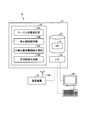
- FIG. 2 is a functional block diagram illustrating the management apparatus according to the present embodiment.
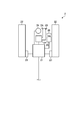
- FIG. 3 is a schematic diagram illustrating an example of the structure of the excavator according to the present embodiment.
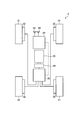
- FIG. 4 is a schematic diagram showing an example of the structure of the dump truck according to the present embodiment.
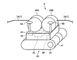
- FIG. 5A is a schematic diagram illustrating an example of the structure of the power relay cart according to the present embodiment.
- FIG. 5-2 is a perspective view showing a modification of the relay support according to the present embodiment.
- FIG. 6 is a flowchart showing a method for setting the travel prohibited area according to the present embodiment.
- FIG. 1 is a diagram illustrating a site where a management apparatus according to the present embodiment is applied.
- FIG. 2 is a functional block diagram illustrating the management apparatus according to the present embodiment.
- FIG. 3 is a schematic diagram illustrating an example of the structure of the excav
- FIG. 7 is an explanatory diagram showing a method for setting the travel prohibited area according to the present embodiment.
- FIG. 8 is an explanatory diagram illustrating a first modification of the method for estimating the position of the cable in the method for setting the prohibited travel area according to the present embodiment.
- FIG. 9A is an explanatory diagram of a second modification of the method for estimating the position of the cable in the method for setting the prohibited travel area according to the present embodiment.
- FIG. 9-2 is an explanatory diagram showing a second modification of the method for estimating the cable position in the method for setting the travel prohibited area according to the present embodiment.
- FIG. 9-3 is an explanatory diagram illustrating a second modification of the method for estimating the cable position in the method for setting the travel prohibited area according to the present embodiment.
- FIG. 9A is an explanatory diagram of a second modification of the method for estimating the position of the cable in the method for setting the prohibited travel area according to the present embodiment.
- FIG. 9-2 is an explanatory diagram showing a second modification
- FIG. 9-4 is an explanatory diagram showing a second modification of the method for estimating the cable position in the method for setting the travel prohibited area according to the present embodiment.
- FIG. 10 is an explanatory diagram showing a method for setting the travel prohibited area according to this comparative example.
- FIG. 11 is a flowchart of a method for generating the moving direction of the relay support according to the present embodiment.
- FIG. 12 is an explanatory diagram of a method for generating the moving direction of the relay support according to the present embodiment.
- FIG. 1 is a diagram illustrating a site where a management apparatus according to the present embodiment is applied.
- the management device 10 included in the travel prohibition area setting system 100 for an unmanned travel vehicle sets a travel prohibition area for an unmanned travel vehicle that travels and works in a mining mine 1 as a work place. Used for.
- the travel prohibition area setting system 100 for unmanned travel vehicles is not limited to the mine, and for example, travel prohibition of equipment used in construction sites such as creation, plants, factories, airports, and harbors. This can be applied even when an area is set.
- the mining site 1 is surrounded by a mining side 1G, an entrance side 1I, and side portions 1Ba and 1Bb.
- the mine 1 shown in the present embodiment is merely an example, and there are actually various forms of mine.
- an excavator 2 as a mining machine for mining ore and the like
- a dump truck 3 as a transporting vehicle for carrying earth and sand or rocks generated during mining of the ore or ore are working.
- the dump truck 3 is an unmanned traveling vehicle capable of unmanned traveling and earth removal.
- the excavator 2 is an electrically driven machine driven by electricity.
- the excavator 2 corresponds to an electric work machine that operates by receiving power supply from the power source via the cable 7.
- the excavator 2 can be mined and traveled unattended.
- the dump truck 3 carries the ore mined by the excavator 2 or the earth and sand or rocks generated during the mining of the ore on the loading platform.
- the dump truck 3 can travel unattended.
- the dump truck 3 is a machine (mine machine) used in the mine mining site 1, it mainly travels on an unpaved road.
- the excavator 2 is supplied with power from the external power supply unit 6 via a cable 7 included in the power relay cart 4 as a relay support.
- the relay support is a device that is arranged between a support (support column 5) described later and the electric work machine (excavator 2) and supports the cable 7 so that it can move, It may be movable by other means.
- the power relay carriage 4 is erected at a position where the cable 7 is drawn into the mining site 1 and adjusts the length of the cable 7 between the support column 5 and the shovel 2 as a support body that supports the cable 7. It is a device that can run unattended.
- the cable 7 closer to the excavator 2 than the power relay cart 4 is referred to as a first cable 7A
- the cable 7 closer to the support column 5 than the power relay cart 4 is referred to as a second cable 7B.
- the power relay cart 4 is not necessarily required.
- the shovel 2 is controlled by the shovel control device 2P.
- the dump truck 3 is controlled by the dump control device 3P.
- the power relay truck 4 is controlled by the relay truck control device 4P.
- the shovel control device 2P, the dump control device 3P, and the relay cart control device 4P are, for example, MCUs (Micro Control Units).
- the excavator 2, the dump truck 3, and the power relay truck 4 have a function of receiving radio waves from GPS (Global Positioning System) satellites 8a, 8b, and 8c and grasping their own positions.
- GPS Global Positioning System
- the excavator 2, the dump truck 3, and the power relay cart 4 have GPS antennas 2A, 3A, and 4A, respectively, in order to receive radio waves from the GPS satellites 8a, 8b, and 8c. Further, the excavator 2, the dump truck 3, and the power relay truck 4 have radio communication antennas 2B, 3B, and 4B, respectively, for exchanging information with the management apparatus 10 by radio.
- the management device 10 is connected to the shovel control device 2P, the dump control device 3P, and the relay truck control device 4P by radio communication via the radio communication antennas 2B, 3B, and 4B, the management device side radio communication antenna 18A, and the communication device 18. Directly exchange information. Note that the management device 10 may exchange information with the excavator control device 2P, the dump control device 3P, and the relay truck control device 4P via a communication line.
- the dump truck 3 and the power relay cart 4 can be run unattended and the operation is controlled by the management device 10. Further, the excavator 2 is driven and operated by an operator's operation.
- the ore mined by the excavator 2 is carried out of the mine 1 by the dump truck 3.
- the dump truck 3 enters the mining site 1 through the passage 9 leading to the mining site 1 and travels in the mining site 1 to the position of the excavator 2.
- the dump truck 3 loaded with ore and the like by the excavator 2 travels from the mining site 1 through the passage 9 to the ore accumulation site or the earth discharging site.
- the dump truck 3 travels along the travel route PL set in advance by the management device 10 in order to travel unattended.
- the excavator 2 is supplied with electric power from the external power supply unit 6, and thus the cable 7 is disposed in the mining site 1. If the dump truck 3 or the excavator 2 passes over the cable 7, the durability of the cable 7 may be reduced. Therefore, the predetermined range with respect to the cable 7 is the travel of the vehicle such as the excavator 2 and the dump truck 3.
- the prohibited travel area DA is to be prohibited.
- a region that is separated by a predetermined distance on both sides with respect to the cable 7 and that is surrounded by the boundary line BL along the cable 7 is defined as a travel prohibition region DA.
- an area other than the travel prohibition area DA of the mining site 1 is defined as a travelable area PA where the excavator 2 and the dump truck 3 can travel.
- the excavator 2, the dump truck 3 and the like travel only in the travelable area PA and do not enter the travel prohibited area DA.
- the management device 10 when generating the travel route PL of the dump truck 3, the management device 10 generates the travel route PL in the travelable area PA except for the travel prohibition area DA of the mining site 1.
- the power relay cart 4 can enter and travel to the travel prohibited area DA.
- FIG. 2 is a functional block diagram illustrating the management apparatus according to the present embodiment.
- the management device 10 includes a processing device 11, a display device 16, an input device 17, and a communication device 18.
- the processing device 11 includes a calculation unit 12, a storage unit 13, and an input / output unit (I / O) 15.
- the processing device 11 is, for example, a computer.
- the arithmetic unit 12 is, for example, a CPU (Central Processing Unit).
- the storage unit 13 is, for example, a RAM (Random Access Memory), a ROM (Read Only Memory), a flash memory, a hard disk drive, or the like.
- the input / output unit 15 is used for input / output of information between the processing device 11 and the display device 16, the input device 17, and the communication device 18 connected to the outside of the processing device 11.
- the calculation unit 12 includes a cable position estimation unit 12A, a prohibited area setting unit 12B, a relay position movement information generation unit 12C, and a travel route generation unit 12D.
- the cable position estimation unit 12A is based at least on the apparatus position information as information on the position of the excavator 2, information on the position of the support column 5 that supports the cable 7, and the length of the cable 7 from the excavator 2 to the support column 5.
- the position of the cable 7 is estimated.
- the cable position estimation unit 12 ⁇ / b> A determines the position of the cable 7 based at least on the information regarding the position of at least two positions between the shovel 2 and the support column 5 and the length of the cable 7 from the shovel 2 to the support column 5. Can also be estimated.
- the prohibition area setting unit 12B sets the travel prohibition area DA that prohibits traveling of the vehicle based on the position of the cable 7 estimated by the cable position estimation unit 12A.
- the relay position movement information generation unit 12C sets the direction along the cable 7 (first cable 7A) between the power relay cart 4 and the excavator 2 as the direction in which the power relay cart 4 moves.
- the travel route generation unit 12D determines that the dump truck 3 is located in the mining area 1 based on information on the position of the mining area 1 (mining area position information) and information on the position of the travel prohibition area DA (travel prohibition area position information).
- a travel route PL for traveling is generated.
- the functions of the cable position estimation unit 12A, the prohibited area setting unit 12B, the relay position movement information generation unit 12C, and the travel route generation unit 12D are unmanned for the processing device 11 that is a computer to realize the functions of the cable position estimation unit 12A and the like. This is realized by reading a computer program for setting a travel prohibition area of the traveling vehicle from the storage unit 13 and executing it.
- the storage unit 13 stores the computer program, the database (DB) 14 and the like.
- the database 14 is a database in which information used for operation management of the excavator 2, the dump truck 3, the power relay cart 4, and the like is described.
- the display device 16 is a liquid crystal display, for example, and displays information necessary for operation management of the excavator 2, the dump truck 3, and the power relay cart 4.
- the input device 17 is, for example, a keyboard, a touch panel, a mouse, or the like, and inputs information necessary for operation management of the excavator 2, the dump truck 3, and the power relay cart 4.
- the communication device 18 includes a management device-side wireless communication antenna 18A, and exchanges information with the above-described excavator control device 2P, dump control device 3P, and relay truck control device 4P by wireless communication. Next, the structure of the excavator 2 will be described.
- FIG. 3 is a schematic diagram illustrating an example of the structure of the excavator according to the present embodiment.
- the excavator 2 is an electrically driven power shovel. The operation of the excavator 2 is controlled by the operator boarding and driving.
- the excavator 2 includes an excavator control device 2P, an electric motor control device 21, a pair of crawler belts 22, two traveling electric motors 23, a turning electric motor 24, an oil pressure generating electric motor 25, a hydraulic pump 26, and GPS.
- An antenna 2A and a radio communication antenna 2B are included.
- the excavator 2 travels by driving the respective crawler belts 22 by two traveling motors 23.
- the turning electric motor 24 turns the upper turning body of the excavator 2.
- the hydraulic pressure generating electric motor 25 drives the hydraulic pump 26 to generate hydraulic pressure necessary for driving the working machine (an apparatus including a boom, an arm, and a bucket) included in the excavator 2.
- the electric motor control device 21 is supplied with electric power from the external power supply unit 6 shown in FIG.
- the electric motor control device 21 supplies electric power to the traveling electric motor 23, the turning electric motor 24, and the hydraulic pressure generating electric motor 25 in response to a command from the excavator control device 2P to drive them.
- the shovel control device 2P controls the motor control device 21 to control driving or regeneration of the traveling motor 23, the turning motor 24, and the hydraulic pressure generating motor 25.
- the traveling electric motor 23 and the electric rotating motor 24 generate electric power (regeneration).
- the shovel control device 2P controls the electric motor control device 21 to return the electric power generated by the traveling electric motor 23 and the turning electric motor 24 to the electric power supply system via the electric power relay truck 4.
- the excavator control device 2P exchanges information with the management device 10 shown in FIG. 1 via the wireless communication antenna 2B, and the radio waves from the GPS satellites 8a, 8b, and 8c obtained from the GPS antenna 2A.
- the shovel control device 2P has a function as a work machine position detection device that detects information related to the position of the shovel 2.
- the excavator control device 2P also has a function as a work machine communication device that transmits information on the position of the excavator 2 detected by the excavator control device 2P.
- the elements of the excavator 2 driven by the electric motor are not limited to those described above.
- the excavator 2 may use an electric motor only for driving the crawler belt 22, may use an electric motor only for driving the work implement, or may use an electric motor only for turning the upper revolving structure.
- the excavator 2 may use an electric motor for at least one drive of the crawler belt 22, the work implement, and the upper swing body. For example, when an electric motor is used to drive the work machine, the electric motor can be driven to generate electric power when the boom is lowered.
- the excavator control device 2P causes the excavator 2 to travel according to the operation of the operator, or causes the excavator 2 to excavate ore or earth and sand.
- the operation of the shovel 2 may be controlled by the management device 10 remotely controlling the shovel control device 2P.
- the excavator control device 2P acquires information related to traveling or excavation of the excavator 2 from the storage unit 13 of the management device 10, and recognizes the position of the excavator 2 by using radio waves from the GPS satellites 8a, 8b, and 8c. Or excavating the excavator 2 may be used.
- FIG. 4 is a schematic diagram showing an example of the structure of the dump truck according to the present embodiment.
- the dump truck 3 includes a dump control device 3P, a plurality of (four in this embodiment) wheels 31, an electric motor 32 that drives each wheel 31, an internal combustion engine 33, a generator 34, and an electric motor control device 35. And a GPS antenna 2A and a radio communication antenna 2B.
- the drive format of the dump truck 3 is a so-called in-wheel motor format in which the electric motor 32 is disposed on the inner peripheral side of the wheel 31, but is not limited thereto.
- the dump truck 3 is equipped with the electric motor 32 in all the wheels 31, you may equip the electric motor 32 only with two rear wheels or two front wheels, for example.
- at least two of the four wheels 31 are steering wheels, but all the wheels 31 may be steering wheels.
- Each electric motor 32 is driven by electric power generated by a generator 34 driven by an internal combustion engine 33.
- the electric power (AC power) generated by the generator 34 is input to a motor control device 35 having an inverter, and then supplied to a plurality of motors 32 to drive them.
- the dump control device 3P controls the motor control device 35 to control the driving or regeneration of each motor 32.
- the motor control device 35 is also connected to the current collector 36.
- the electric motor control device 35 can also drive the electric motor 32 by receiving power supply from the overhead wire TL via the current collecting device 36. Further, by using the electric motor 32 as a generator when the dump truck 3 is braked, the electric motor 32 can generate electric power (regeneration) while braking the dump truck 3.
- the electric power generated at this time is charged into a power storage device such as a capacitor or a secondary battery mounted on the dump truck 3, for example.
- the dump control device 3P exchanges information with the management device 10 shown in FIG. 1 via the wireless communication antenna 2B. Further, the dump control device 3P drives the electric motor 32 with electric power obtained by the internal combustion engine 33 driving the generator 34. Further, the dump control device 3P exchanges information with the management device 10 shown in FIG. 1 via the radio communication antenna 3B, and the radio waves from the GPS satellites 8a, 8b, and 8c obtained from the GPS antenna 3A. To obtain the self-position and transmit it to the management apparatus 10.
- the dump control device 3P has a function as an unmanned vehicle position detection device that detects information related to the position of the dump truck 3.
- the dump control device 3P also has a function as an unmanned vehicle communication device that transmits information on the position of the dump truck 3 detected by the dump control device 3P.
- the dump control device 3P causes the dump truck 3 to travel in accordance with a command from the management device 10, or lowers the ore that is the load.
- the dump control device 3P is remotely operated by the management device 10.
- the dump control device 3 acquires the travel route PL from the storage unit 13 of the management device 10 and recognizes its own position by radio waves from the GPS satellites 8a, 8b, 8c, while following the travel route PL. May be used.
- FIG. 5A is a schematic diagram illustrating an example of the structure of the power relay cart according to the present embodiment.
- the power relay cart 4 includes a traveling device 40, a cart 43, a first cable drum 44A, a second cable drum 44B, a relay cart control device 4P, a power transmission relay unit 45 to which the cable 7 is connected, and a GPS unit.
- An antenna 4A, a radio communication antenna 4B, and a communication device 46 are included.
- the traveling device 40 includes a pair of left and right crawler belts 41 and a pair of left and right traveling motors 42 that generate power by electric power to drive the crawler belts 41.
- the traveling device 40 is connected to the carriage 43.
- the traveling device 40 causes the power relay carriage 4 to travel by causing the traveling motor 42 to drive the crawler belt 41.
- the traveling device 40 is preferably a crawler type using a crawler belt 41, but may be other than the crawler type such as using a tire. In this way, the power relay cart 4 can travel and move by the traveling device 40.
- the first cable drum 44A is a device capable of winding and sending out the first cable 7A
- the second cable drum 44B is a device capable of winding and sending out the second cable 7B.
- the first cable drum 44 ⁇ / b> A and the second cable drum 44 ⁇ / b> B are both mounted on the carriage 43.
- the first cable drum 44A and the second cable drum 44B have a cylindrical shaft portion, and the inside has a hollow structure. An opening that communicates the inside and the outside of the shaft portion is formed in a part of the shaft portion. Further, the first cable drum 44A and the second cable drum 44B regulate the winding range in the axial direction of the shaft portion when the first cable 7A and the second cable 7B wind or send the first cable 7A and the second cable 7B.
- the guide portion is a disk-shaped member and is provided near both ends of the shaft portion.
- the central axis of the disc coincides with the central axis of the shaft portion.
- One end of each of the first cable 7A and the second cable 7B enters the inside of the shaft portion from the opening of the shaft portion.
- the first cable 7A and the second cable 7B are configured such that the end portions on the side entering the inside of the shaft portion of the first cable drum 44A and the inside of the shaft portion of the second cable drums 44B and 34 are the respective shaft portions. It is pulled out from one end of the shaft to the outside of the shaft, and is connected to a power transmission relay unit 45 held by the carriage 43. In this way, the power transmission relay unit 45 to which the first cable 7A and the second cable 7B are connected relays the first cable 7A and the second cable 7B.
- the power transmission relay unit 45 may be a device that performs only electrical relay between the first cable 7A and the second cable 7B, or a relay cart control device 4P that controls the power relay cart 4 is provided. The power transmission relay unit 45 may also be used.
- the first cable drum 44A and the second cable drum 44B are connected to a cable driving motor.
- the electric motor for driving the cable rotates the first cable drum 44A and the second cable drum 44B around the respective central axes as rotation axes.
- the first cable drum 44A and the second cable drum 44B can wind and send out the first cable 7A and the second cable 7B, respectively.
- Each of the first cable drum 44A and the second cable drum 44B is such that the rotational axes of the first cable drum 44A and the second cable drum 44B are orthogonal to the input / output shaft of the electric motor 42 for driving the crawler belt 41, and The rotating shafts are arranged so as to be parallel to the front-rear direction of the power relay carriage 4.
- the first cable 7 ⁇ / b> A is electrically connected to the shovel 2 at the end opposite to the end connected to the power transmission relay unit 45, and exchanges power with the shovel 2.
- the second cable 7 ⁇ / b> B is electrically connected to the external power supply unit 6 at the end opposite to the end connected to the power transmission relay unit 45. Exchange.
- the first cable drum 44 and the second cable drum 44 ⁇ / b> B are arranged such that their respective rotation axes are parallel to the front-rear direction of the power relay carriage 4.
- the second cable 7B and the first cable 7A extend in opposite directions in the front-rear direction of the power relay truck 4.
- the relay truck control device 4P controls the operation of the traveling motor 42 to run or stop the power relay truck 4, or drives the cable driving motor, thereby the first cable drum 44A and the second cable drum 44B.
- the first cable 7A and the second cable 7B are wound or sent out.
- the relay truck control device 4P exchanges information with the management device 10 shown in FIG. 1 via the communication device 46 and the wireless communication antenna 4B. Further, the relay truck control device 4P obtains its own position from the radio waves from the GPS satellites 8a, 8b and 8c obtained from the GPS antenna 4A, and transmits it to the management device 10 via the communication device 46 and the wireless communication antenna 4B. To do.
- the relay truck control device 4P functions as a relay support body position detection device that detects information related to the position of the relay support body.
- the communication device 46 has a function as a relay support body communication device that transmits information on the position of the power relay cart 4 detected by the relay cart control device 4P.
- the relay cart control device 4P runs the power relay cart 4 based on the information obtained from the management device 10, and winds or sends out the cable 7.
- the structure of the power relay truck 4 is not limited to this, and the number of drums that winds or sends out the cable 7 may be one.
- the relay truck control device 4P causes the power relay truck 4 to travel, winds and sends out the cable 7 in accordance with instructions from the management device 10. In this way, the relay truck control device 4P is remotely operated by the management device 10. In addition, the relay truck control device 4P acquires information related to the traveling of the power relay truck 4 from the storage unit 13 of the management device 10, and recognizes its position from the radio waves from the GPS satellites 8a, 8b, and 8c, You may make it drive
- FIG. 5-2 is a perspective view showing a modification of the relay support according to the present embodiment.
- the mobile relay support 4S as a relay support includes a support 47, a cable support 48, an insulator 48S, a lifting hook 48F, and a base 49.
- One end of the column 47 is fixed to the pedestal 49, and the other end is attached to the cable support 48.
- the cable support 48 is a rod-shaped member, and insulators 48S are attached to both ends.
- the insulator 48S supports the cable 7 shown in FIG. 1 and electrically insulates the cable 7 from the cable support 48, the column 47, and the pedestal 49.
- the pulling hook 48 ⁇ / b> F is attached near the center of the cable support 48.
- the mobile relay column 4S is installed in the mine 1 shown in FIG. 1 and supports the cable 7 between the support column 5 and the shovel 2.
- the mobile relay post 4S When moving the mobile relay post 4S, for example, the mobile relay post 4S is lifted by a crane or the like via the lifting hook 48F of the mobile relay post 4S and moved to a different location in the mining site 1.
- the relay support is not limited to a device that can be self-propelled, such as the power relay cart 4 described above, and may be moved by other moving means, such as the mobile relay column 4S. Good.
- the mobile relay column 4S transmits a relay support body position detection device that detects information about the position of the mobile relay column 4S, and information about the position of the mobile relay column 4S detected by the relay support body position detection device.
- a relay support communication device may be mounted.
- the said relay support body position detection apparatus calculates
- the cable position estimation unit 12A of the management device 10 estimates the position of the cable 7 using the acquired information regarding the position of the mobile relay column 4S.
- the mobile relay support column 4S may not be mounted with the relay support body position detection device and the relay support body communication device.
- information on the position of the mobile relay column 4 is acquired from, for example, the GPS satellites 8a, 8b, and 8c. Then, the worker updates the acquired information on the position of the mobile relay column 4 in the storage unit 13 of the management device 10.
- a travel prohibited area setting method travel prohibited area setting method for an unmanned traveling vehicle according to the present embodiment will be described.
- FIG. 6 is a flowchart showing a method for setting the travel prohibited area according to the present embodiment.
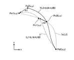
- FIG. 7 is an explanatory diagram showing a method for setting the travel prohibited area according to the present embodiment.
- the method for setting the travel prohibited area according to the present embodiment is realized by the management device 10 in the travel prohibited area setting system 100 for the unmanned traveling vehicle shown in FIG. That is, the calculation unit 12 of the management device 10 illustrated in FIG. 2 reads and executes the travel prohibition region setting computer program for the unmanned traveling vehicle stored in the storage unit 13, thereby executing the travel prohibition region according to the present embodiment.
- the setting method is realized.
- the number of power relay carts 4 is one, but the number of power relay carts 4 is not limited to one.
- the management device 10 advances the process to step S102 when the initial value is changed in step S101 (step S101, Yes). When there is no change (No at Step S101), the process proceeds to Step S103.
- the initial value is set for the management apparatus 10 in step S102.
- the initial value is input to the storage unit 13 by the input device 17 when the operator operates the input device 17 of the management device 10.
- the change of the initial value includes a case where the initial value is input to the management apparatus 10 from a state where the initial value does not exist.
- the initial values are, for example, the position of the excavator 2 before the start of mining, the position of the power relay cart 4, the position of the support pillar 5, the length of the cable 7 from the support pillar 5 to the shovel 2, and the cable 7 Position, etc.
- the initial value is set before the start of mining, it is normally not changed until the mining at the mining site is completed, and is newly set when the excavator 2 or the like moves to a different mining site. In the mining site, when the position of the excavator 2 or the like greatly moves or the cable 7 or the power relay cart 4 is replaced, the initial value may be reset.
- the position of the excavator 2, the position of the power relay truck 4, the position of the support pillar 5, the position of the cable 7 and the like are represented using xy coordinates.
- the initial value (initial position) of the position of the excavator 2 is Pa0 (x, y)
- the initial value (initial position) of the position of the support column 5 is Pb0 (x, y)
- the position of the power relay carriage 4 is The initial value (initial position) is assumed to be Pc0 (x, y).
- the initial value (initial length) L0 of the length of the cable 7 is the initial value (initial value) of the length of the first cable 7A.
- the initial position of the cable 7 is, for example, a set of coordinates obtained by measuring the position of the cable 7 before the start of mining at a predetermined interval between the support column 5 and the shovel 2.
- a set of these coordinates may be approximated by a predetermined function (such as a quadratic function or a cubic function) to obtain the initial position of the cable 7.
- a predetermined function such as a quadratic function or a cubic function
- the initial position of the cable 7 is obtained and set for each of the first cable 7A and the second cable 7B.
- values actually measured in the field may be used, the excavator 2, the power relay cart 4, etc.
- the position information of the excavator 2 and the power relay cart 4 acquired through the GPS antennas 2A, 4A, etc. included in the vehicle may be used.
- step S103 the cable position estimation unit 12A of the management device 10 executes step S104 when there is a cable position update request (Yes in step S103).
- step S103 when there is no request for updating the cable position (step S103, No), the management device 10 executes the method for setting the travel prohibited area according to the present embodiment from the beginning again.
- the case where there is a request for updating the cable position is a case where a flag (update request flag) for requesting the update of the position of the cable 7 is generated in the method for setting the travel prohibited area according to the present embodiment.
- the update request flag is generated, for example, when the movement distance of at least one of the excavator 2 and the power relay truck 4 exceeds a predetermined movement distance threshold.
- the management apparatus 10 updates the position of the cable 7 and resets the travel prohibition area DA.
- the excavator 2 moves from the initial position Pa0 (x, y) in the direction indicated by the arrow m1, and the power relay cart 4 exceeds the movement distance threshold in the direction indicated by the arrow m2 from the initial position Pc0 (x, y). And move.
- the position of the excavator 2 after movement is Pa1 (x, y), and the position of the power relay cart 4 is Pc1 (x, y). Since the position of the support pillar 5 does not change, it is Pb0 (x, y). In this case, since there is a request for updating the cable position (step S103, Yes), the cable position estimation unit 12A acquires the position information of the excavator 2 and the power relay cart 4 in step S104.
- the cable position estimation unit 12A transmits a command to transmit the position information to the excavator 2 and the power relay cart 4 via the communication device 18. Then, the excavator control device 2P of the excavator 2 and the relay cart control device 4P of the power relay cart 4 acquire radio waves from the GPS satellites 8a, 9b, and 9c, calculate their own positions (position information), and perform wireless communication. The data is transmitted from the antennas 2B and 4B to the management device side wireless communication antenna 18A of the management device 10.
- the cable position estimation unit 12 ⁇ / b> A acquires the position information of the excavator 2 and the power relay cart 4 via the communication device 18.
- the position information of the excavator 2 is coordinates Pa1 (x, y) after movement
- the position information of the power relay truck 4 is coordinates Pc1 (x, y) after movement.
- the cable position estimation unit 12A is connected to the relay cart control device 4P of the power relay cart 4 via the communication device 18.
- the length L1 of the cable 7 is also acquired.
- the length of the first cable 7A after movement of the excavator 2 and the power relay cart 4 is L1A
- the length of the second cable 7B is L1B
- the method for estimating the position of the cable 7 is, for example, a function that passes through three coordinates Pa1 (x, y), Pb0 (x, y), and Pc1 (x, y) after the excavator 2 or the like is moved.
- a method of obtaining by interpolation for example, spline interpolation.
- interpolation for example, spline interpolation
- the condition that the length of the cable 7 between the coordinates Pa1 (x, y) of the shovel 2 and the coordinates Pb0 (x, y) of the support column 5 after the movement is L1 is given.
- the value before the movement is used as the length L1 of the cable 7 after the movement.
- the cable position estimating unit 12A calculates the three coordinates Pa1 (x, y), Pb0 (x, y), and Pc1 (x, y) under the condition that the length of the cable 7 is L1. Find the function that passes.
- the cable 7 indicated by a two-dot chain line in FIG. 7 passes through three coordinates Pa1 (x, y), Pb0 (x, y), and Pc1 (x, y), and has a length L1. Therefore, the cable position estimation unit 12A replaces the position of the cable 7 stored in the storage unit 13 with the function representing the two-dot chain line cable 7 as the position of the cable 7 after movement. In this way, the cable position estimation unit 12A estimates the position of the cable 7 after the excavator 2 and the like have moved, and updates the position of the cable 7 before the movement.
- the cable position estimating unit 12A causes the length to be L2 when the difference between the estimated length L2 of the cable 7a and the length L1 of the cable 7 used for estimation exceeds a predetermined threshold.
- the cable 7a is excluded as a candidate for the cable 7 after the excavator 2 or the like is moved.
- the cable position estimation unit 12A can estimate the position of the cable 7 after movement more accurately by using the length L1 of the cable 7 before movement as a constraint condition.
- FIG. 8 is an explanatory diagram illustrating a first modification of the method for estimating the position of the cable in the method for setting the prohibited travel area according to the present embodiment.
- the cable position estimation unit 12 ⁇ / b> A performs estimation using information regarding the position of the excavator 2, information regarding the position of the power relay cart 4, and information regarding the position of the support pillar 5. That is, the cable position estimation unit 12A is information regarding three positions between the shovel 2 and the support column 5 (including the positions of both ends of the cable 7, that is, the position of the shovel 2 and the position of the support column 5). Was used to estimate the position of the cable 7.
- the cable position estimation unit 12A includes position information (positions of both ends of the cable 7, that is, the position of the shovel 2 and the position of the support column 5) between the shovel 2 and the support column 5. ) Is used to estimate the position of the cable 7.
- the cable position estimation unit 12A includes coordinates Pa1 (x, y) as position information of the excavator 2 after movement, coordinates Pb0 (x, y) as position information of the support column 5, and the length of the cable 7 after movement. Based on the length L1, the position of the cable 7 after the excavator 2 or the like is moved is estimated.
- the method for estimating the position of the cable 7 is, for example, a function passing through two coordinates Pa1 (x, y) and Pb0 (x, y) after the excavator 2 or the like is moved, for example, interpolation (for example, spline).
- the cable position estimation unit 12A obtains a function that passes through two coordinates Pa1 (x, y) and Pb0 (x, y) under the condition that the length of the cable 7 is L1.
- the cable 7 indicated by a two-dot chain line in FIG. 8 passes through two coordinates Pa1 (x, y) and Pb0 (x, y) and has a length L1. Therefore, the cable position estimation unit 12A replaces the position of the cable 7 stored in the storage unit 13 with the function representing the two-dot chain line cable 7 as the position of the cable 7 after movement. In this way, the cable position estimation unit 12A estimates the position of the cable 7 after the excavator 2 and the like have moved.
- the cable 7a indicated by the dotted line in FIG. 8 passes through two coordinates Pa1 (x, y) and Pb0 (x, y), but the length L2 of the cable 7a is different from L1 (in this example, L2> L1). For this reason, the cable position estimation unit 12A excludes the cable 7a as the cable 7 after the excavator 2 moves.
- the cable 7b shown by the dotted line in FIG. 8 passes through two coordinates Pa1 (x, y) and Pb0 (x, y), and the length of the cable 7b is L1, and the cable used for estimation 7 equal to the length L1.
- the cable 7 before the movement has a convex shape in the xy coordinate system
- the cable 7b after the movement has a convex shape in the xy coordinate system. That is, the shape between the coordinates Pa0 (x, y) and the coordinates Pb0 (x, y) of the function indicating the cable 7 before the excavator 2 moves is convex upward in the xy coordinate system.
- the shape between the coordinates Pa1 (x, y) and the coordinates Pb1 (x, y) of the function indicating the cable 7b after the movement changes convexly downward.
- FIGS. 9-1 to 9-4 are explanatory views showing a second modification of the method for estimating the position of the cable in the method for setting the prohibited travel area according to the present embodiment.
- the cable position estimation unit 12A uses the history of the position change of the power relay truck 4 due to the movement of the power relay truck 4 as the relay support, as information on the position of the power relay truck 4 (relay point position information). ).
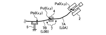
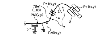
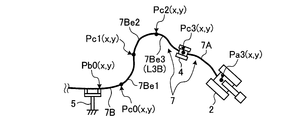
- FIGS. 9-1 to 9-4 show an example in which the power relay cart 4 moves while sending out the second cable 7B as the excavator 2 moves.
- the initial values of the excavator 2 are the coordinates Pa0 (x, y), the initial position of the support column 5 is the coordinates Pb0 (x, y), and the initial position of the power relay cart 4 is the coordinates Pc (x, y). y).
- the position of the excavator 2 is in the order of coordinates Pa0 (x, y) to Pa1 (x, y), Pa2 (x, y), Pa3 (x, y). Change.
- the position of the power relay carriage 4 changes in the order of coordinates Pc0 (x, y) to Pc1 (x, y), Pc2 (x, y), Pc3 (x, y).
- the extension 7Be1, 7Be2, 7Be3 is sent out to the second cable 7B.
- the length of the second cable 7B is a value obtained by sequentially adding the extensions L1B, L2B, and L3B to the initial length L0B as the position of the power relay carriage 4 changes. In this example, the length of the first cable 7A does not change, but this length may also change.
- the cable position estimation unit 12A When the position of the cable 7 when the excavator 2 moves to the coordinate Pa3 (x, y) is estimated, the cable position estimation unit 12A has a history of movement of the power relay cart 4, that is, when the power relay cart 4 moves. Coordinates Pc0 (x, y), Pc1 (x, y), Pc2 (x, y), and Pc3 (x, y) are used.
- the cable position estimation unit 12A performs a function passing through four coordinates Pc0 (x, y), Pc1 (x, y), Pc2 (x, y), Pc3 (x, y), for example, by interpolation (for example, , Spline interpolation), and this is the position of the cable 7 after the excavator 2 or the like has moved.
- interpolation for example, , Spline interpolation
- the length (L1B + L2B + L3B) of the cable 7B from the coordinates Pc0 (x, y) to Pc3 (x, y) is used as the constraint condition, but this is the same as in the above-described embodiment.
- the cable position estimation unit 12A has four coordinates Pc0 (x, y), Pc1 (x, y), Pc2 (x, y), and Pc3 (x, y) obtained by moving the power relay carriage 4. And a function that passes through the coordinates Pb0 (x, y) of the support column 5 and the coordinates Pa3 (x, y) of the shovel 2 after the movement is obtained by, for example, interpolation (for example, spline interpolation). It is set as the position of the cable 7 after etc. move.
- interpolation for example, spline interpolation
- the length (L0B + L1B + L2B + L3B + L0A) of the cable 7B from the coordinates Pb0 (x, y) to Pa3 (x, y) is used as the constraint condition, and this point is as described above.
- the position of the cable 7 after the excavator 2 or the like has moved is estimated using the history of movement of the power relay cart 4. For this reason, since the positional information (coordinates accompanying the movement of the power relay cart 4) that can be used when estimating the cable 7 can be increased, the estimation accuracy of the position of the cable 7 after the movement is improved.
- step S106 the prohibited area setting unit 12B of the management device 10 prohibits the traveling of the vehicle (the excavator 2, the dump truck 3, etc. in the present embodiment) based on the position of the cable 7 estimated by the cable position estimating unit 12A. It is set as the travel prohibition area DA.
- the prohibited area setting unit 12B sets a predetermined area around the position of the cable 7 after the excavator 2 or the like is moved as a travel prohibited area DA as shown in FIG.
- the prohibited area setting unit 12B generates two boundary lines along the cable 7 that are separated by a predetermined distance on both sides around the position of the cable 7 after the excavator 2 or the like is moved. Then, the prohibited area setting unit 12B sets the area surrounded by the two boundary lines as the travel prohibited area DA and stores it in the storage unit 13. Next, proceeding to step S107, the prohibited area setting unit 12B replaces the previous travel prohibited area DA stored in the storage unit 13 with the travel prohibited area DA newly set in step S106, thereby prohibiting travel. Update area DA. When the travel prohibition area DA is updated, the management apparatus 10 again executes the travel prohibition area setting method according to the present embodiment from the beginning.
- the travel route generation unit 12D of the management apparatus 10 reads the new travel prohibition area DA from the storage unit 13 and determines the travel path PL of the dump truck 3 in the mine 1 shown in FIG. Generate. At this time, the travel route generation unit 12D generates a travel route PL in the travelable region PA by setting the region excluding the travel prohibition region DA from the entire region of the mine 1 as the travelable region PA. The management device 10 causes the dump truck 3 to travel in the mine 1 based on the newly generated travel route PL.
- the travel route generation unit 12D When the travel route generation unit 12D generates the travel route PL, for example, when the failed vehicle is stopped in the travelable area PA of the mining site 1, the travel route generation unit 12D travels in a predetermined region around the failed vehicle. After setting as the prohibited area DA, the travel route PL is generated. By doing in this way, since the driving
- the cable position estimating unit 12 ⁇ / b> A includes information on at least two positions between the shovel 2 and the support pillar 5, the shovel 2 and the support.
- the position of the cable 7 after the excavator 2 or the like has moved is estimated based at least on the length of the cable 7 between the column 5 and the column 5.
- FIG. 10 is an explanatory diagram showing a method for setting the travel prohibited area according to this comparative example.
- the travel prohibition area DA is set based on a range in which the excavator 2 and the cable 7 are considered to move in the mine 1. In this way, considering the movement of the excavator 2 and the cable 7, it is necessary to set the travel prohibition area DA with a margin, so the travel prohibition area DA becomes larger and the travelable area PA becomes smaller. Become. Therefore, the degree of freedom when setting the travel route PL of the dump truck 3 is reduced, and an unreasonable travel route PL may be inevitably set.
- the first modified example, and the second modified example when the excavator 2 or the power relay cart 4 moves, the position of the cable 7 is estimated, and a predetermined area around the cable 7 is re-established as the travel prohibition area DA. Since it is set, the travel prohibition area DA can be minimized. As a result, since the travelable area PA of the mining site 1 is increased, the degree of freedom when setting the travel route PL of the dump truck 3 is improved. For this reason, this embodiment, the 1st modification, and the 2nd modification have the advantage that it becomes easy to set the turning route, the passing of the dump trucks 3, or the travel route PL which has allowances in the retreat place.
- the dump truck 3 is taken as an example of traveling unattended.
- the dump truck 3 may be operated by a manned person, that is, a driver who has boarded the dump truck 3.
- the management device 10 displays the generated travel route PL on a monitor provided in the driver's seat of the dump truck 3 so that the dump truck 3 travels along the travel route PL. Guide the driver.
- FIG. 11 is a flowchart of a method for generating the moving direction of the relay support according to the present embodiment.
- FIG. 12 is an explanatory diagram of a method for generating the moving direction of the relay support according to the present embodiment.
- a function of the relay position movement information generation unit 12C of the management apparatus 10 illustrated in FIG. 2 will be described.
- the relay position movement information generation unit 12 ⁇ / b> C indicates the direction along the cable 7 (first cable 7 ⁇ / b> A) existing between the power relay cart 4 as the relay support and the excavator 2 as the electric work machine. Is the direction of movement. When the excavator 2 moves, the power relay cart 4 may also be moved.
- step S201 the relay position movement information generating unit 12C of the management device 10 illustrated in FIG.
- the process proceeds to step S202 (step S201, Yes).
- step S204 the relay position movement information generation unit 12C advances the process to step S204 (No in step S201). The contents of step S204 will be described later.
- step S202 the relay position movement information generation unit 12C reads out and acquires the position of the cable 7 (cable position) at the time of processing in step S202 from the storage unit 13. In addition, the relay position movement information generation unit 12C acquires the position of the shovel 2 at the time of processing in step S202 from the shovel control device 2P via the communication device 18.
- step S203 the relay position movement information generation unit 12C sets a target position (target position) when the power relay cart 4 moves, and the length of the cable 7 (cable length) required at that time. L1A is set.
- the excavator 2 moves from the coordinate Pa0 (x, y) to Pa1 (x, y) (the direction indicated by the arrow m1 in FIG. 12), and the power relay carriage 4 has the coordinate Pc0 (x, y).
- the curvature of the cable 7 (the two-dot chain line in FIG. 12) after the movement is set to be the largest.
- the method for setting the target position and the cable length is not limited to this.
- step S204 the process proceeds to step S204, and the relay position movement information generation unit 12C moves the power relay carriage 4 toward the target position, so that the cable length set in step S203 is obtained.
- the first cable drum 44A is controlled.
- step S205 the relay position movement information generation unit 12C acquires the current position information.
- This position information is information regarding the position of the excavator 2 and information regarding the position of the power relay cart 4.
- step S206 the cable position estimation part 12A of the management apparatus 10 estimates the position of the cable 7 at the present time based on the positional information acquired by step S205, and makes it memorize
- step S207 the management apparatus 10 proceeds to step S208 when the power relay carriage 4 reaches the target position (coordinates Pc1 (x, y)) (step S207, Yes), and has not reached the target position.
- the process returns to step S201, and the subsequent procedures are executed.
- step S208 the prohibited area setting unit 12B of the management device 10 illustrated in FIG.
- the travel prohibition area DA is updated by newly setting DA and storing the DA in the storage unit 13.
- the management apparatus 10 can reduce the load of the cable 7 and suppress the deterioration of the durability of the cable 7 by moving the power relay cart 4 along the cable 7.
- this embodiment and its modification are the information regarding the position of at least two places between the electric work machine which receives supply of electric power from the power supply via the cable and the support body supporting the cable, and the electric type
- the position of the cable is estimated based at least on the length of the cable from the work machine to the support.
- a travel prohibition area is set in which a machine operated in a work site such as a mining site is prohibited from traveling. In this way, the travel prohibited area can be suppressed to a necessary and sufficient range, so that the travel prohibited area in the work place can be reduced and the travelable area can be increased.
- the degree of freedom in setting the travel route of equipment used in the workplace is improved, the range in which the equipment can be moved is widened, the load on the equipment is reduced, and there is a margin.
- the device can be operated.
- the use of electrically driven excavators is increasing, and cables are often routed around the mine. This embodiment and its modification are suitable for mines where an electrically driven excavator is used via a cable.
Landscapes
- Engineering & Computer Science (AREA)
- Remote Sensing (AREA)
- Radar, Positioning & Navigation (AREA)
- General Engineering & Computer Science (AREA)
- Structural Engineering (AREA)
- Civil Engineering (AREA)
- Mining & Mineral Resources (AREA)
- Aviation & Aerospace Engineering (AREA)
- Physics & Mathematics (AREA)
- General Physics & Mathematics (AREA)
- Automation & Control Theory (AREA)
- Operation Control Of Excavators (AREA)
- Control Of Position, Course, Altitude, Or Attitude Of Moving Bodies (AREA)
- Component Parts Of Construction Machinery (AREA)
Abstract
Description
図1は、本実施形態に係る管理装置が適用される現場を示す図である。本実施形態において、無人走行車両の走行禁止領域設定システム100に含まれる管理装置10は、作業場としての鉱山の採掘場1を走行したり作業したりする無人走行車両の走行禁止領域を設定する際に用いられる。なお、無人走行車両の走行禁止領域設定システム100は、適用対象が鉱山に限定されるものではなく、例えば、造成、プラント、工場、空港又は港湾等の建設現場等において使用される機器の走行禁止領域を設定する場合であっても適用することができる。
図2は、本実施形態に係る管理装置を示す機能ブロック図である。管理装置10は、処理装置11と、表示装置16と、入力装置17と、通信装置18とを含む。処理装置11は、演算部12と、記憶部13と、入出力部(I/O)15とを含む。処理装置11は、例えば、コンピュータである。演算部12は、例えば、CPU(Central Processing Unit)である。記憶部13は、例えば、RAM(Random Access Memory)、ROM(Read Only Memory)、フラッシュメモリ、ハードディスクドライブ等である。入出力部15は、処理装置11と、処理装置11の外部に接続する表示装置16、入力装置17及び通信装置18との情報の入出力に用いられる。
図3は、本実施形態に係るショベルの構造の一例を示す模式図である。上述したように、ショベル2は電気駆動式パワーショベルである。ショベル2は、作業者が搭乗して運転することにより、動作が制御される。ショベル2は、ショベル制御装置2Pと、電動機制御装置21と、一対の履帯22と、2つの走行用電動機23と、旋回用電動機24と、油圧生成用電動機25と、油圧ポンプ26と、GPS用アンテナ2Aと、無線通信用アンテナ2Bとを含む。
図4は、本実施形態に係るダンプトラックの構造の一例を示す模式図である。ダンプトラック3は、ダンプ制御装置3Pと、複数(本実施形態では4個)の車輪31と、それぞれの車輪31を駆動する電動機32と、内燃機関33と、発電機34と、電動機制御装置35と、GPS用アンテナ2Aと、無線通信用アンテナ2Bとを含む。ダンプトラック3の駆動形式は、車輪31の内周側に電動機32が配置される、いわゆるインホイールモータ形式であるが、これに限定されるものではない。また、ダンプトラック3は、すべての車輪31に電動機32を備えているが、例えば、後輪2輪又は前輪2輪のみに電動機32を備えていてもよい。ダンプトラック3は、4個の車輪31のうち、少なくとも2輪が操舵輪となるが、すべての車輪31が操舵輪となってもよい。それぞれの電動機32は、内燃機関33によって駆動される発電機34が生み出した電力によって駆動される。
図5-1は、本実施形態に係る電力中継台車の構造の一例を示す模式図である。電力中継台車4は、走行装置40と、台車43と、第1ケーブルドラム44Aと、第2ケーブルドラム44Bと、中継台車制御装置4Pと、ケーブル7が接続される送電中継部45と、GPS用アンテナ4Aと、無線通信用アンテナ4Bと、通信装置46と、を含む。走行装置40は、左右一対の履帯41と、電力によって動力を発生して履帯41を駆動させる左右一対の走行用電動機42とを有している。走行装置40は、台車43と連結されている。走行装置40は、走行用電動機42に履帯41が駆動させることにより、電力中継台車4を走行させる。走行装置40は、履帯41を用いる履帯式が好ましいが、タイヤを用いる等、履帯式以外であってもよい。このように、電力中継台車4は、走行装置40によって走行し、移動することができる。
図5-2は、本実施形態に係る中継支持体の変形例を示す斜視図である。中継支持体としての移動中継支柱4Sは、支柱47と、ケーブル支持体48と、絶縁体48Sと、引上げ用フック48Fと、台座49とを含む。支柱47は、一方の端部が台座49に固定されており、他方の端部がケーブル支持体48に取り付けられている。ケーブル支持体48は、棒状の部材であり、両端部に絶縁体48Sが取り付けられている。絶縁体48Sは、図1に示すケーブル7を支持するとともに、ケーブル7と、ケーブル支持体48、支柱47及び台座49との間を電気的に絶縁する。引上げ用フック48Fは、ケーブル支持体48の中央部近傍に取り付けられている。
図6は、本実施形態に係る走行禁止領域の設定方法を示すフローチャートである。図7は、本実施形態に係る走行禁止領域の設定方法を示す説明図である。本実施形態に係る走行禁止領域の設定方法は、図1に示す無人走行車両の走行禁止領域設定システム100において、管理装置10が実現する。すなわち、図2に示す管理装置10の演算部12は、記憶部13に保存されている無人走行車両の走行禁止領域設定用コンピュータプログラムを読み込んで実行することにより、本実施形態に係る走行禁止領域の設定方法を実現する。次の説明において、電力中継台車4は1台であるが、電力中継台車4の台数は1台に限定されるものではない。本実施形態に係る走行禁止領域の設定方法を実行するにあたり、管理装置10は、ステップS101において、初期値に変更があった場合(ステップS101、Yes)、処理をステップS102へ進め、初期値に変更がなかった場合(ステップS101、No)、処理をステップS103へ進める。
図8は、本実施形態に係る走行禁止領域の設定方法において、ケーブルの位置を推定する手法の第1変形例を示す説明図である。上述した例において、ケーブル位置推定部12Aは、ショベル2の位置に関する情報と、電力中継台車4の位置に関する情報と、支持柱5の位置に関する情報とを用いて推定した。すなわち、ケーブル位置推定部12Aは、ショベル2と支持柱5との間における三箇所の位置に関する情報(ケーブル7の両端部の位置、すなわち、ショベル2の位置及び支持柱5の位置情報を含む)を用いてケーブル7の位置を推定した。本変形例において、ケーブル位置推定部12Aは、ショベル2と支持柱5との間における二箇所の位置情報(ケーブル7の両端部の位置、すなわち、ショベル2の位置及び支持柱5の位置を含む)を用いてケーブル7の位置を推定する。
図9-1から図9-4は、本実施形態に係る走行禁止領域の設定方法において、ケーブルの位置を推定する手法の第2変形例を示す説明図である。本変形例において、ケーブル位置推定部12Aは、中継支持体としての電力中継台車4が移動したことによる電力中継台車4の位置変化の履歴を、電力中継台車4の位置に関する情報(中継点位置情報)として用いる。図9-1から図9-4は、ショベル2の移動にともなって電力中継台車4は第2ケーブル7Bを送り出しながら移動している例を示している。初期値は、ショベル2の初期位置は座標Pa0(x、y)であり、支持柱5の初期位置は座標Pb0(x、y)であり、電力中継台車4の初期位置は座標Pc(x、y)である。
図11は、本実施形態に係る中継支持体の移動方向を生成する方法のフローチャートである。図12は、本実施形態に係る中継支持体の移動方向を生成する方法の説明図である。図2に示す管理装置10の中継位置移動情報生成部12Cの機能を説明する。中継位置移動情報生成部12Cは、中継支持体としての電力中継台車4と電気式作業機械としてのショベル2の間に存在するケーブル7(第1ケーブル7A)に沿った方向を、電力中継台車4が移動する方向とする。ショベル2が移動した場合、電力中継台車4も移動させることがあるが、このときに、ケーブル7に沿った方向(図12の矢印m2で示す方向)へ電力中継台車4を移動させることにより、ケーブル7に与えられる負荷を低減できるので好ましい。次に、中継支持体の移動方向を生成する方法の手順を説明する。
1Ba、1Bb 側部
1G 採掘側
1I 入口側
2A、3A、4A GPS用アンテナ
2 ショベル
2P ショベル制御装置
2B、3B、4B 無線通信用アンテナ
3 ダンプトラック
3P ダンプ制御装置
4 電力中継台車
4P 中継台車制御装置
4S 移動中継支柱
5 支持柱
6 外部電源部
7 ケーブル
7A 第1ケーブル
7B 第2ケーブル
8a、8b、8c GPS衛星
9 通路
10 管理装置
11 処理装置
12 演算部
12A ケーブル位置推定部
12B 禁止領域設定部
12C 中継位置移動情報生成部
12D 走行経路設定部
13 記憶部
14 データベース
15 入出力部
16 表示装置
17 入力装置
18 通信装置
18A 管理装置側無線通信用アンテナ
21 電動機制御装置
22 履帯
23 走行用電動機
24 旋回用電動機
25 油圧生成用電動機
26 油圧ポンプ
31 車輪
32 電動機
33 内燃機関
34 発電機
35 電動機制御装置
36 集電装置
40 走行装置
41 履帯
42 走行用電動機
43 台車
44A 第1ケーブルドラム
44B 第2ケーブルドラム
45 送電中継部
46 通信装置
47 支柱
48 ケーブル支持体
48S 絶縁体
48F 用フック
49 台座
Claims (11)
- 外部電源からケーブルを介して電力の供給を受けて動作する電動式作業機械と、
前記電動式作業機械に搭載されて、前記電動式作業機械の位置に関する情報を検出する作業機械位置検出装置と、
前記電動式作業機械に搭載されて、前記作業機械位置検出装置が検出した前記電動式作業機械の位置に関する情報を送信する作業機械通信装置と、
前記ケーブルを支持する支持体と、
前記作業機械通信装置から送信された前記電動式作業機械の位置に関する情報を受信する通信装置を有する管理装置と、を含み、
前記管理装置は、
少なくとも、前記電動式作業機械の位置に関する情報と、前記支持体の位置に関する情報と、前記電動式作業機械から前記支持体までの前記ケーブルの長さとに基づいて、前記ケーブルの位置を推定し、
推定された前記ケーブルの位置に基づいて、無人で走行する車両の走行を禁止する走行禁止領域を設定することを特徴とする無人走行車両の走行禁止領域設定システム。 - さらに、前記支持体と前記電動式作業機械との間に配置されて、前記ケーブルを移動可能に支持する中継支持体を有し、
前記管理装置は、
前記中継支持体の位置に関する情報を用いて前記ケーブルの位置を推定する請求項1に記載の無人走行車両の走行禁止領域設定システム。 - 前記中継支持体は、
前記中継支持体に搭載されて、前記中継支持体の位置に関する情報を検出する中継支持体位置検出装置と、
前記中継支持体に搭載されて、前記中継支持体位置検出装置が検出した前記中継支持体の位置に関する情報を送信する中継支持体通信装置と、を有し、
前記管理装置は、
前記中継支持体位置検出装置が検出した前記中継支持体の位置に関する情報を用いて前記ケーブルの位置を推定する請求項1に記載の無人走行車両の走行禁止領域設定システム。 - 前記管理装置は、
前記中継支持体が移動したことによる前記中継支持体の位置変化の履歴を前記中継支持体の位置に関する情報として用いる請求項2又は3に記載の無人走行車両の走行禁止領域設定システム。 - さらに、前記管理装置は、
前記中継支持体と前記電気式作業機械との間の前記ケーブルに沿った方向を、前記中継支持体が移動する方向とする請求項1から4のいずれか1項に記載の無人走行車両の走行禁止領域設定システム。 - 前記電気式作業機械は、鉱山で使用される電気駆動式パワーショベルである請求項1から5のいずれか1項に記載の無人走行車両の走行禁止領域設定システム。
- 外部電源からケーブルを介して電力の供給を受けて動作する電動式作業機械が作業する作業場において、無人で走行する車両の走行を禁止する走行禁止領域を設定するにあたり、
コンピュータに、
前記電動式作業機械の位置に関する情報と、前記ケーブルを支持する支持体の位置に関する情報と、前記電動式作業機械から前記支持体までのケーブルの長さとに少なくとも基づいて、前記ケーブルの位置を推定する手順と、
推定された前記ケーブルの位置に基づいて、前記走行禁止領域を設定する手順と、
を実行させることを特徴とする無人走行車両の走行禁止領域設定用コンピュータプログラム。 - 前記支持体と前記電気式作業機械との間に配置されて、前記ケーブルを移動可能に支持する中継支持体の位置に関する情報を用いて前記ケーブルの位置が推定される請求項7に記載の無人走行車両の走行禁止領域設定用コンピュータプログラム。
- 前記中継支持体が移動したことによる前記中継支持体の位置変化の履歴が前記中継支持体の位置に関する情報として用いられる請求項8に記載の無人走行車両の走行禁止領域設定用コンピュータプログラム。
- さらに、前記中継支持体と前記電気式作業機械との間の前記ケーブルに沿った方向が、前記中継支持体が移動する方向とされる請求項7から9のいずれか1項に記載の無人走行車両の走行禁止領域設定用コンピュータプログラム。
- 前記電気式作業機械は、鉱山で使用される電気駆動式パワーショベルである請求項7から10のいずれか1項に記載の無人走行車両の走行禁止領域設定用コンピュータプログラム。
Priority Applications (4)
| Application Number | Priority Date | Filing Date | Title |
|---|---|---|---|
| CA2836570A CA2836570C (en) | 2011-06-17 | 2012-06-15 | Travel-restricted area setting system for unmanned traveling vehicle and computer program for setting travel-restricted area of unmanned traveling vehicle |
| US14/119,044 US9377779B2 (en) | 2011-06-17 | 2012-06-15 | Travel-restricted area setting system for unmanned traveling vehicle and computer program for setting travel-restricted area of unmanned traveling vehicle |
| CN201280027946.6A CN103597146B (zh) | 2011-06-17 | 2012-06-15 | 无人驾驶车辆禁止行驶区域设定系统以及无人驾驶车辆禁止行驶区域设定方法 |
| AU2012270472A AU2012270472B2 (en) | 2011-06-17 | 2012-06-15 | Travel-prohibited area setting system for unpiloted vehicle and computer program for setting travel-prohibited area for unpiloted vehicle |
Applications Claiming Priority (2)
| Application Number | Priority Date | Filing Date | Title |
|---|---|---|---|
| JP2011135042A JP5866645B2 (ja) | 2011-06-17 | 2011-06-17 | 無人走行車両の走行禁止領域設定システム及び無人走行車両の走行禁止領域設定用コンピュータプログラム |
| JP2011-135042 | 2011-06-17 |
Publications (1)
| Publication Number | Publication Date |
|---|---|
| WO2012173256A1 true WO2012173256A1 (ja) | 2012-12-20 |
Family
ID=47357234
Family Applications (1)
| Application Number | Title | Priority Date | Filing Date |
|---|---|---|---|
| PCT/JP2012/065427 Ceased WO2012173256A1 (ja) | 2011-06-17 | 2012-06-15 | 無人走行車両の走行禁止領域設定システム及び無人走行車両の走行禁止領域設定用コンピュータプログラム |
Country Status (6)
| Country | Link |
|---|---|
| US (1) | US9377779B2 (ja) |
| JP (1) | JP5866645B2 (ja) |
| CN (1) | CN103597146B (ja) |
| AU (1) | AU2012270472B2 (ja) |
| CA (1) | CA2836570C (ja) |
| WO (1) | WO2012173256A1 (ja) |
Cited By (1)
| Publication number | Priority date | Publication date | Assignee | Title |
|---|---|---|---|---|
| US9475496B2 (en) | 2013-11-22 | 2016-10-25 | Ford Global Technologies, Llc | Modified autonomous vehicle settings |
Families Citing this family (24)
| Publication number | Priority date | Publication date | Assignee | Title |
|---|---|---|---|---|
| KR20150009740A (ko) * | 2013-07-17 | 2015-01-27 | 한국전자통신연구원 | 이동체 귀환 방법 및 장치 |
| JP6285838B2 (ja) * | 2014-09-29 | 2018-02-28 | 日立建機株式会社 | 作業車両の移動制御装置及び作業車両 |
| JP6382688B2 (ja) * | 2014-11-06 | 2018-08-29 | 日立建機株式会社 | 地図生成装置 |
| EP4622315A3 (en) * | 2015-03-31 | 2025-11-26 | SZ DJI Technology Co., Ltd. | Open platform for restricted region |
| US9681033B2 (en) | 2015-04-06 | 2017-06-13 | Caterpillar Inc. | System for tracking cable tethered from machine |
| US9773175B2 (en) | 2015-07-09 | 2017-09-26 | Caterpillar Inc. | System and method for tracking position of cable attached to a machine |
| AU2015243312A1 (en) * | 2015-10-19 | 2017-05-04 | Caterpillar Of Australia Pty Ltd | System and method for controlling access to a crest area |
| CA2926299C (en) | 2015-10-30 | 2019-04-30 | Komatsu Ltd. | Mine management system and mine managing method |
| JP6736426B2 (ja) * | 2016-08-31 | 2020-08-05 | 株式会社Ihiエアロスペース | ケーブル繰り出し装置 |
| US9864375B1 (en) | 2016-11-21 | 2018-01-09 | Caterpillar Inc. | Area isolation system |
| US10920401B2 (en) | 2018-07-26 | 2021-02-16 | Caterpillar Paving Products Inc. | Managing work area reservations for autonomous vehicles |
| JP7156898B2 (ja) * | 2018-10-10 | 2022-10-19 | 株式会社小松製作所 | 運搬車両と運搬車両に素材を積み込む作業機械とを含むシステム、方法、及び作業機械 |
| JP7257240B2 (ja) * | 2019-04-24 | 2023-04-13 | 株式会社小松製作所 | 作業機械を制御するためのシステムおよび方法 |
| JP7303027B2 (ja) * | 2019-06-03 | 2023-07-04 | 株式会社小松製作所 | 作業機械を制御するためのシステムおよび方法 |
| JP7040809B2 (ja) | 2020-03-19 | 2022-03-23 | Totalmasters株式会社 | 建設現場管理装置 |
| CN111364539A (zh) * | 2020-04-14 | 2020-07-03 | 杭州登元科技有限公司 | 一种纯电驱动无人驾驶推煤机 |
| SE544397C2 (en) * | 2020-09-10 | 2022-05-10 | Epiroc Rock Drills Ab | Method and system for restricting operation of at least one automated mining vehicle |
| JP7743721B2 (ja) * | 2021-07-05 | 2025-09-25 | コベルコ建機株式会社 | 作業現場監視システム |
| US20240302840A1 (en) * | 2021-09-16 | 2024-09-12 | Abb Schweiz Ag | Electronic device and method of controlling unmanned ground vehicle |
| EP4407103A4 (en) * | 2021-09-24 | 2025-08-13 | Hitachi Construction Mach Co | CONSTRUCTION MACHINERY CONTROL SYSTEM AND CONSTRUCTION MACHINERY |
| CN114326469B (zh) * | 2021-11-26 | 2023-12-08 | 江苏徐工工程机械研究院有限公司 | 一种无人矿山智能辅助作业安全控制方法及系统 |
| JP7700076B2 (ja) * | 2022-03-30 | 2025-06-30 | 日立建機株式会社 | 車両管理システム |
| KR20260047246A (ko) * | 2023-09-29 | 2026-04-07 | 히다치 겡키 가부시키 가이샤 | 전력 제어 시스템 및 전력 제어 방법 |
| US12338010B1 (en) | 2024-11-27 | 2025-06-24 | Wonny Kim | System for electrically powered aerial platforms to draw power from ground-based stations |
Citations (3)
| Publication number | Priority date | Publication date | Assignee | Title |
|---|---|---|---|---|
| JPH08158403A (ja) * | 1994-12-01 | 1996-06-18 | Hitachi Constr Mach Co Ltd | 旋回式掘削機のケーブル巻取り装置とその制御用油圧回路 |
| JP2008140375A (ja) * | 2006-11-07 | 2008-06-19 | Komatsu Ltd | 無人車両の誘導走行制御方法および制御装置 |
| JP2010065445A (ja) * | 2008-09-10 | 2010-03-25 | Hitachi Constr Mach Co Ltd | 電動式作業機械 |
Family Cites Families (14)
| Publication number | Priority date | Publication date | Assignee | Title |
|---|---|---|---|---|
| JPS54125801A (en) * | 1978-03-23 | 1979-09-29 | Kawasaki Heavy Ind Ltd | Power feeder for electromorive bulldozer |
| US4587383A (en) * | 1983-06-27 | 1986-05-06 | Marathon Letourneau Company | Electrically powered mobile apparatus and method with suspended power cable |
| WO2001073223A2 (en) | 2000-03-31 | 2001-10-04 | Hitachi Construction Machinery Co., Ltd. | Work managing method suited to work site, managing system, and managing apparatus |
| JP2005256469A (ja) * | 2004-03-12 | 2005-09-22 | Hitachi Constr Mach Co Ltd | 施工作業領域の設定・管理システム |
| WO2006028966A1 (en) * | 2004-09-01 | 2006-03-16 | Siemens Energy & Automation, Inc. | Method for an autonomous loading shovel |
| EP1862988B1 (en) * | 2006-05-30 | 2009-11-04 | Mazda Motor Corporation | A driving assist for a vehicle |
| US7931133B2 (en) * | 2008-01-16 | 2011-04-26 | Soave Enterprises L.L.C. | System for self-adjusting height and direction of a movable power cable |
| US7958982B2 (en) * | 2008-04-29 | 2011-06-14 | Caterpilar Inc. | Cable guide having a signaling instrument |
| US7793442B2 (en) * | 2008-04-29 | 2010-09-14 | Caterpillar Inc | Avoidance system for locating electric cables |
| JP5169572B2 (ja) * | 2008-07-22 | 2013-03-27 | 日産自動車株式会社 | 情報提供装置及び情報提供方法 |
| AU2010256515B2 (en) * | 2009-06-03 | 2016-06-09 | Flsmidth A/S | Mining methods and systems using mobile conveyors |
| US8332106B2 (en) * | 2009-10-21 | 2012-12-11 | Caterpillar Inc. | Tether tracking system and method for mobile machine |
| US8863921B2 (en) * | 2010-04-30 | 2014-10-21 | Abraham Cohen | 360-degree freedom electric cord device and system |
| US8820509B2 (en) * | 2010-12-14 | 2014-09-02 | Caterpillar Inc. | Autonomous mobile conveyor system |
-
2011
- 2011-06-17 JP JP2011135042A patent/JP5866645B2/ja not_active Expired - Fee Related
-
2012
- 2012-06-15 CA CA2836570A patent/CA2836570C/en not_active Expired - Fee Related
- 2012-06-15 AU AU2012270472A patent/AU2012270472B2/en not_active Ceased
- 2012-06-15 WO PCT/JP2012/065427 patent/WO2012173256A1/ja not_active Ceased
- 2012-06-15 CN CN201280027946.6A patent/CN103597146B/zh not_active Expired - Fee Related
- 2012-06-15 US US14/119,044 patent/US9377779B2/en not_active Expired - Fee Related
Patent Citations (3)
| Publication number | Priority date | Publication date | Assignee | Title |
|---|---|---|---|---|
| JPH08158403A (ja) * | 1994-12-01 | 1996-06-18 | Hitachi Constr Mach Co Ltd | 旋回式掘削機のケーブル巻取り装置とその制御用油圧回路 |
| JP2008140375A (ja) * | 2006-11-07 | 2008-06-19 | Komatsu Ltd | 無人車両の誘導走行制御方法および制御装置 |
| JP2010065445A (ja) * | 2008-09-10 | 2010-03-25 | Hitachi Constr Mach Co Ltd | 電動式作業機械 |
Cited By (1)
| Publication number | Priority date | Publication date | Assignee | Title |
|---|---|---|---|---|
| US9475496B2 (en) | 2013-11-22 | 2016-10-25 | Ford Global Technologies, Llc | Modified autonomous vehicle settings |
Also Published As
| Publication number | Publication date |
|---|---|
| JP2013002161A (ja) | 2013-01-07 |
| CA2836570A1 (en) | 2012-12-20 |
| CA2836570C (en) | 2016-10-18 |
| JP5866645B2 (ja) | 2016-02-17 |
| US20140107882A1 (en) | 2014-04-17 |
| CN103597146A (zh) | 2014-02-19 |
| US9377779B2 (en) | 2016-06-28 |
| AU2012270472B2 (en) | 2015-09-03 |
| CN103597146B (zh) | 2016-07-20 |
| AU2012270472A1 (en) | 2013-11-28 |
Similar Documents
| Publication | Publication Date | Title |
|---|---|---|
| JP5866645B2 (ja) | 無人走行車両の走行禁止領域設定システム及び無人走行車両の走行禁止領域設定用コンピュータプログラム | |
| US8843311B2 (en) | Drive system for unmanned vehicle and method of drive control of the same | |
| JP5362691B2 (ja) | 無人車両の走行システムにおける走行制御方法および無人車両の走行システム | |
| CN103597685B (zh) | 带有杆的缆索中继台车及向电动式工作机械供给电力的电力供给系统 | |
| JP6159031B2 (ja) | 作業機械の管理装置 | |
| JP6267059B2 (ja) | 車両管理システム | |
| JP6339412B2 (ja) | 交通管制サーバ | |
| KR20220030098A (ko) | 자율 작업 굴착기 및 그의 동작 방법 | |
| KR102423054B1 (ko) | 자율 주행 방법 및 이를 이용하는 무인 도저 | |
| JP6151366B2 (ja) | タイヤ管理システム及びタイヤ管理方法 | |
| EP4261646B1 (en) | Scanner emulation for mining vehicle | |
| JP2017199395A (ja) | 作業機械の管理方法 | |
| WO2023188650A1 (ja) | 車両管理システム | |
| JP2019139809A (ja) | 作業機械の管理装置及び作業機械の管理方法 | |
| US12298758B2 (en) | Systems and methods for operating a controller area network | |
| EP4325319A1 (en) | Obstacle avoidance trajectory for a mining vehicle | |
| AU2024356939A1 (en) | Vehicle and vehicle management system |
Legal Events
| Date | Code | Title | Description |
|---|---|---|---|
| 121 | Ep: the epo has been informed by wipo that ep was designated in this application |
Ref document number: 12800995 Country of ref document: EP Kind code of ref document: A1 |
|
| ENP | Entry into the national phase |
Ref document number: 2836570 Country of ref document: CA |
|
| WWE | Wipo information: entry into national phase |
Ref document number: 14119044 Country of ref document: US |
|
| ENP | Entry into the national phase |
Ref document number: 2012270472 Country of ref document: AU Date of ref document: 20120615 Kind code of ref document: A |
|
| NENP | Non-entry into the national phase |
Ref country code: DE |
|
| 122 | Ep: pct application non-entry in european phase |
Ref document number: 12800995 Country of ref document: EP Kind code of ref document: A1 |