WO2012172624A1 - 一方向性電磁鋼板の製造方法 - Google Patents
一方向性電磁鋼板の製造方法 Download PDFInfo
- Publication number
- WO2012172624A1 WO2012172624A1 PCT/JP2011/063475 JP2011063475W WO2012172624A1 WO 2012172624 A1 WO2012172624 A1 WO 2012172624A1 JP 2011063475 W JP2011063475 W JP 2011063475W WO 2012172624 A1 WO2012172624 A1 WO 2012172624A1
- Authority
- WO
- WIPO (PCT)
- Prior art keywords
- steel sheet
- insulating film
- glass film
- laser irradiation
- coil
- Prior art date
- Legal status (The legal status is an assumption and is not a legal conclusion. Google has not performed a legal analysis and makes no representation as to the accuracy of the status listed.)
- Ceased
Links
Images


Classifications
-
- C—CHEMISTRY; METALLURGY
- C21—METALLURGY OF IRON
- C21D—MODIFYING THE PHYSICAL STRUCTURE OF FERROUS METALS; GENERAL DEVICES FOR HEAT TREATMENT OF FERROUS OR NON-FERROUS METALS OR ALLOYS; MAKING METAL MALLEABLE, e.g. BY DECARBURISATION OR TEMPERING
- C21D8/00—Modifying the physical properties of ferrous metals or ferrous alloys by deformation combined with, or followed by, heat treatment
- C21D8/12—Modifying the physical properties of ferrous metals or ferrous alloys by deformation combined with, or followed by, heat treatment during manufacturing of articles with special electromagnetic properties
- C21D8/1216—Modifying the physical properties of ferrous metals or ferrous alloys by deformation combined with, or followed by, heat treatment during manufacturing of articles with special electromagnetic properties characterised by the working steps
- C21D8/1222—Hot rolling
-
- C—CHEMISTRY; METALLURGY
- C21—METALLURGY OF IRON
- C21D—MODIFYING THE PHYSICAL STRUCTURE OF FERROUS METALS; GENERAL DEVICES FOR HEAT TREATMENT OF FERROUS OR NON-FERROUS METALS OR ALLOYS; MAKING METAL MALLEABLE, e.g. BY DECARBURISATION OR TEMPERING
- C21D8/00—Modifying the physical properties of ferrous metals or ferrous alloys by deformation combined with, or followed by, heat treatment
- C21D8/12—Modifying the physical properties of ferrous metals or ferrous alloys by deformation combined with, or followed by, heat treatment during manufacturing of articles with special electromagnetic properties
- C21D8/1216—Modifying the physical properties of ferrous metals or ferrous alloys by deformation combined with, or followed by, heat treatment during manufacturing of articles with special electromagnetic properties characterised by the working steps
- C21D8/1233—Cold rolling
-
- C—CHEMISTRY; METALLURGY
- C21—METALLURGY OF IRON
- C21D—MODIFYING THE PHYSICAL STRUCTURE OF FERROUS METALS; GENERAL DEVICES FOR HEAT TREATMENT OF FERROUS OR NON-FERROUS METALS OR ALLOYS; MAKING METAL MALLEABLE, e.g. BY DECARBURISATION OR TEMPERING
- C21D8/00—Modifying the physical properties of ferrous metals or ferrous alloys by deformation combined with, or followed by, heat treatment
- C21D8/12—Modifying the physical properties of ferrous metals or ferrous alloys by deformation combined with, or followed by, heat treatment during manufacturing of articles with special electromagnetic properties
- C21D8/1244—Modifying the physical properties of ferrous metals or ferrous alloys by deformation combined with, or followed by, heat treatment during manufacturing of articles with special electromagnetic properties characterised by the heat treatment
- C21D8/1255—Modifying the physical properties of ferrous metals or ferrous alloys by deformation combined with, or followed by, heat treatment during manufacturing of articles with special electromagnetic properties characterised by the heat treatment with diffusion of elements, e.g. decarburising, nitriding
-
- C—CHEMISTRY; METALLURGY
- C21—METALLURGY OF IRON
- C21D—MODIFYING THE PHYSICAL STRUCTURE OF FERROUS METALS; GENERAL DEVICES FOR HEAT TREATMENT OF FERROUS OR NON-FERROUS METALS OR ALLOYS; MAKING METAL MALLEABLE, e.g. BY DECARBURISATION OR TEMPERING
- C21D8/00—Modifying the physical properties of ferrous metals or ferrous alloys by deformation combined with, or followed by, heat treatment
- C21D8/12—Modifying the physical properties of ferrous metals or ferrous alloys by deformation combined with, or followed by, heat treatment during manufacturing of articles with special electromagnetic properties
- C21D8/1244—Modifying the physical properties of ferrous metals or ferrous alloys by deformation combined with, or followed by, heat treatment during manufacturing of articles with special electromagnetic properties characterised by the heat treatment
- C21D8/1272—Final recrystallisation annealing
-
- C—CHEMISTRY; METALLURGY
- C21—METALLURGY OF IRON
- C21D—MODIFYING THE PHYSICAL STRUCTURE OF FERROUS METALS; GENERAL DEVICES FOR HEAT TREATMENT OF FERROUS OR NON-FERROUS METALS OR ALLOYS; MAKING METAL MALLEABLE, e.g. BY DECARBURISATION OR TEMPERING
- C21D8/00—Modifying the physical properties of ferrous metals or ferrous alloys by deformation combined with, or followed by, heat treatment
- C21D8/12—Modifying the physical properties of ferrous metals or ferrous alloys by deformation combined with, or followed by, heat treatment during manufacturing of articles with special electromagnetic properties
- C21D8/1277—Modifying the physical properties of ferrous metals or ferrous alloys by deformation combined with, or followed by, heat treatment during manufacturing of articles with special electromagnetic properties involving a particular surface treatment
- C21D8/1283—Application of a separating or insulating coating
-
- C—CHEMISTRY; METALLURGY
- C21—METALLURGY OF IRON
- C21D—MODIFYING THE PHYSICAL STRUCTURE OF FERROUS METALS; GENERAL DEVICES FOR HEAT TREATMENT OF FERROUS OR NON-FERROUS METALS OR ALLOYS; MAKING METAL MALLEABLE, e.g. BY DECARBURISATION OR TEMPERING
- C21D8/00—Modifying the physical properties of ferrous metals or ferrous alloys by deformation combined with, or followed by, heat treatment
- C21D8/12—Modifying the physical properties of ferrous metals or ferrous alloys by deformation combined with, or followed by, heat treatment during manufacturing of articles with special electromagnetic properties
- C21D8/1294—Modifying the physical properties of ferrous metals or ferrous alloys by deformation combined with, or followed by, heat treatment during manufacturing of articles with special electromagnetic properties involving a localised treatment
-
- C—CHEMISTRY; METALLURGY
- C22—METALLURGY; FERROUS OR NON-FERROUS ALLOYS; TREATMENT OF ALLOYS OR NON-FERROUS METALS
- C22C—ALLOYS
- C22C38/00—Ferrous alloys, e.g. steel alloys
- C22C38/001—Ferrous alloys, e.g. steel alloys containing N
-
- C—CHEMISTRY; METALLURGY
- C22—METALLURGY; FERROUS OR NON-FERROUS ALLOYS; TREATMENT OF ALLOYS OR NON-FERROUS METALS
- C22C—ALLOYS
- C22C38/00—Ferrous alloys, e.g. steel alloys
- C22C38/02—Ferrous alloys, e.g. steel alloys containing silicon
-
- C—CHEMISTRY; METALLURGY
- C22—METALLURGY; FERROUS OR NON-FERROUS ALLOYS; TREATMENT OF ALLOYS OR NON-FERROUS METALS
- C22C—ALLOYS
- C22C38/00—Ferrous alloys, e.g. steel alloys
- C22C38/04—Ferrous alloys, e.g. steel alloys containing manganese
-
- C—CHEMISTRY; METALLURGY
- C22—METALLURGY; FERROUS OR NON-FERROUS ALLOYS; TREATMENT OF ALLOYS OR NON-FERROUS METALS
- C22C—ALLOYS
- C22C38/00—Ferrous alloys, e.g. steel alloys
- C22C38/06—Ferrous alloys, e.g. steel alloys containing aluminium
-
- H—ELECTRICITY
- H01—ELECTRIC ELEMENTS
- H01F—MAGNETS; INDUCTANCES; TRANSFORMERS; SELECTION OF MATERIALS FOR THEIR MAGNETIC PROPERTIES
- H01F1/00—Magnets or magnetic bodies characterised by the magnetic materials therefor; Selection of materials for their magnetic properties
- H01F1/01—Magnets or magnetic bodies characterised by the magnetic materials therefor; Selection of materials for their magnetic properties of inorganic materials
- H01F1/03—Magnets or magnetic bodies characterised by the magnetic materials therefor; Selection of materials for their magnetic properties of inorganic materials characterised by their coercivity
- H01F1/12—Magnets or magnetic bodies characterised by the magnetic materials therefor; Selection of materials for their magnetic properties of inorganic materials characterised by their coercivity of soft-magnetic materials
- H01F1/14—Magnets or magnetic bodies characterised by the magnetic materials therefor; Selection of materials for their magnetic properties of inorganic materials characterised by their coercivity of soft-magnetic materials metals or alloys
- H01F1/16—Magnets or magnetic bodies characterised by the magnetic materials therefor; Selection of materials for their magnetic properties of inorganic materials characterised by their coercivity of soft-magnetic materials metals or alloys in the form of sheets
- H01F1/18—Magnets or magnetic bodies characterised by the magnetic materials therefor; Selection of materials for their magnetic properties of inorganic materials characterised by their coercivity of soft-magnetic materials metals or alloys in the form of sheets with insulating coating
Definitions
- the present invention relates to a method for producing a unidirectional electrical steel sheet in which a glass film and an insulating film are formed on the surface of a steel plate, and the magnetic domain is controlled by laser irradiation.
- the above-mentioned unidirectional electrical steel sheet is used as a material constituting an iron core of electrical equipment such as a transformer and a rotating machine. Such a unidirectional electrical steel sheet is required to reduce energy loss (iron loss) when magnetized. Iron loss is classified into eddy current loss and hysteresis loss. Furthermore, eddy current loss is classified into classical eddy current loss and abnormal eddy current loss.
- a thin unidirectional electrical steel sheet having an insulating film formed on the plate surface is provided.
- a unidirectional electrical steel sheet on which an insulating film is formed for example, as shown in Patent Document 1, a glass film is formed on the surface of a steel plate, and a two-layer structure in which an insulating film is further formed on the glass film. Structures have been proposed.
- Patent Documents 2 and 3 in order to suppress abnormal eddy current loss, for example, as shown in Patent Documents 2 and 3, a laser beam is condensed and irradiated from above the insulating film, and is scanned in the substantially width direction of the electromagnetic steel sheet.
- a magnetic domain control method has been proposed in which magnetic domains are subdivided by providing regions having residual strain periodically in the direction.
- the above-mentioned unidirectional electrical steel sheet is, for example, a silicon steel slab as a raw material, a hot rolling process ⁇ an annealing process ⁇ a cold rolling process ⁇ a decarburizing annealing process ⁇ a final finish annealing process ⁇ an insulating film forming process ⁇ a laser irradiation process, It is manufactured by the procedure.
- an oxide layer mainly composed of silica (SiO 2 ) is formed on the surface of the steel plate iron.
- the final finishing annealing process it heat-processes using a batch type furnace in the state which wound steel plate iron in the shape of a coil.
- an annealing separator mainly composed of magnesia is applied to the surface of the steel sheet steel before the final finishing annealing process.
- the above glass film is formed by the reaction between the oxide layer mainly composed of silica and the annealing separator mainly composed of magnesia.
- wrinkles may occur in the insulating film and the glass film due to the irradiation of the laser beam.
- wrinkles refers to film damage such as defect peeling, lifting, alteration, and discoloration of these films, which can be recognized by visual inspection or visual inspection under a microscope.
- the steel plate steel is exposed to the outside and rust is generated. For this reason, when wrinkles occurred in the glass film, it was necessary to apply the insulating film again.
- a method for producing a unidirectional electrical steel sheet according to the present invention includes a steel sheet base iron, a glass coating formed on the surface of the steel plate base, and an insulating coating formed on the glass coating.
- a method for producing a steel sheet comprising: annealing in a batch furnace in a state where the steel sheet steel is wound in a coil shape, and forming a glass film on the surface of the steel sheet steel; and the final finishing process.
- a laser beam is irradiated onto the surface facing the radially outer side of the coil in the final finish annealing process.
- heat treatment is performed in a batch furnace in a state where the steel sheet steel is wound in a coil shape, and the surface facing the radially outer side and the surface facing the radially inner side of the coiled steel sheet steel A glass film is formed.
- an insulating film formation process an insulating film is formed on a glass film in the state which unwound the steel plate iron wound by coil shape, and was extended in plate shape.
- the plate surface is irradiated with a laser beam in a state where the steel plate base iron on which the glass film and the insulating film are formed is extended in a plate shape.
- the laser beam is focused and irradiated on the surface facing the radially outer side of the coil in the final finishing annealing process in which the adhesion between the main body of the steel plate (ground iron) and the glass coating has not deteriorated, It is possible to reliably suppress the occurrence of the above and provide a high-quality unidirectional electrical steel sheet.
- a unidirectional electrical steel sheet 10 shown in FIG. 1 includes a steel sheet steel 11 (ground metal), a glass film 12 formed on the surface of the steel sheet steel 11, and an insulating film 13 formed on the glass film 12. It is equipped with.
- the steel plate base iron 11 (base iron) is made of an iron alloy containing Si.
- Si 2.5% by mass to 4.0% by mass
- C 0.02% by mass to 0.10% by mass
- Mn 0.05% by mass to 0.20% by mass
- Acid-soluble Al 0.020% by mass or more and 0.040% by mass or less
- N 0.002% by mass or more and 0.012% by mass or less
- S 0.001% by mass or more and 0.010% by mass or less
- P 0 0.01 mass% or more and 0.04 mass% or less
- the thickness of the steel plate base iron 11 is generally 0.15 mm or more and 0.35 mm or less.
- the glass film 12 is made of a composite oxide such as forsterite (Mg 2 SiO 4 ), spinel (MgAl 2 O 4 ), and cordierite (Mg 2 Al 4 Si 5 O 16 ).
- the thickness of the glass coating 12 is about 1 ⁇ m.
- the insulating film 13 is, for example, (JP-A-48-39338, JP-B-53-28375) a coating liquid mainly composed of colloidal silica and phosphate (magnesium phosphate, aluminum phosphate, etc.) (JP-A-6-65754, JP-A-6-65555)
- the coating liquid is a mixture of alumina sol and boric acid.
- the insulating film 13 is shown for aluminum phosphate, colloidal silica, and chromic anhydride (Japanese Patent Publication No. 53-28375).
- the insulating film 13 has a thickness of about 2 ⁇ m.
- residual strain is given to a linear region substantially orthogonal to the rolling direction by irradiating the insulating film 13 with a laser beam.
- the linear region to which the residual strain is applied is formed in a predetermined cycle in the rolling direction, and in a region sandwiched between two linear regions and magnetized in the rolling direction, a direction substantially orthogonal to the rolling direction. Subdivide the magnetic domain width.
- the method for producing a unidirectional electrical steel sheet includes a casting step S01, a hot rolling step S02, an annealing step S03, a cold rolling step S04, It has a carbon annealing step S05, an annealing separator coating step S06, a final finish annealing step S07, an insulating film forming step S08, and a laser irradiation step S09.
- the molten steel prepared to the above composition is supplied to a continuous casting machine, and the ingot is continuously produced.
- the hot rolling step S02 the obtained ingot is heated to a predetermined temperature (for example, 1150 to 1400 ° C.) to perform hot rolling. Thereby, for example, a hot rolled material having a thickness of 1.8 to 3.5 mm is produced.
- the annealing step S03 heat treatment is performed on the hot-rolled material under conditions of, for example, 750 to 1200 ° C. ⁇ 30 seconds to 10 minutes.
- the cold rolling step S04 the surface of the hot rolled material after the annealing step S03 is pickled and then cold rolling is performed. Thereby, for example, a cold rolled material having a thickness of 0.15 to 0.35 mm is produced.
- the cold-rolled material is heat-treated, for example, under conditions of 700 to 900 ° C. ⁇ 1 to 3 minutes.
- the decarburization annealing step S05 as shown in FIG. 3, the cold rolled material wound up in a coil shape is drawn out in a plate shape, and heat treatment is performed while running in the furnace 21. Thereby, the steel plate iron 11 is produced.
- an oxide layer 15 mainly composed of silica (SiO 2 ) is formed on the surface of the steel plate 11 by the decarburization annealing step S05.
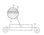
- an annealing separator 16 mainly composed of magnesia (MgO) is applied on the oxide layer 15 as shown in the enlarged cross-sectional view of the steel plate surrounded by circles in FIG.
- MgO magnesia
- the steel plate 11 coated with the annealing separator 16 is wound in a coil shape and charged into the batch furnace 22 to perform heat treatment. .
- the heat treatment condition in the final finish annealing step S07 is 1100 to 1300 ° C. ⁇ 20 to 24 hours.
- the oxide layer 15 mainly composed of silica reacts with the annealing separator 16 mainly composed of magnesia, and as shown in the enlarged cross-sectional view of the steel sheet surrounded by circles in FIG.
- a glass film 12 made of forsterite (Mg 2 SiO 4 ) is formed on the surface of the base iron 11.
- the steel sheet steel 11 wound in a coil shape is unwound, stretched into a plate shape and conveyed, and the glass film formed on both surfaces of the steel sheet metal 11
- An insulating agent 13 is formed on the insulating layer 13 by applying and baking on the insulating layer 12.
- the steel plate base 11 on which the insulating film 13 is formed is wound up in a coil shape.
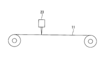
- the steel sheet steel 11 wound in a coil shape is unwound, stretched into a plate shape, and conveyed, and a laser beam is collected toward one surface of the steel sheet steel 11.
- the linear distortion substantially orthogonal to the rolling direction is imparted to the surface of the steel plate 11 at intervals set in advance in the rolling direction.
- the laser irradiation device 23 is arranged so as to irradiate the laser beam onto the surface facing the radially outer side of the coil when charged in the batch furnace 22.
- the light source and type of the laser are not particularly limited as long as they are laser light sources that are usually used for magnetic domain control by laser irradiation.
- an example using a YAG laser is shown in the laser irradiation step S09.
- the glass coating 12 and the insulating coating 13 are formed on the surface of the steel plate base 11, and the unidirectional electrical steel plate 10 whose magnetic domain is controlled by laser irradiation is manufactured.
- the steel sheet base iron 11 coated with the annealing separator 16 is wound in a coil shape in the final finish annealing step S07. Since the heat treatment is performed by charging the batch-type furnace 22 in a heated state, the glass coating 12 is respectively provided on the surface facing the radially outer side and the surface facing the radially inner side of the coiled steel plate iron 11. It is formed.
- the steel sheet steel 11 wound in a coil shape is unwound and stretched into a plate shape and conveyed, and the radial direction of the coil charged in the batch furnace 22 in the final finishing step S07.
- a laser beam is applied to the surface facing outward.
- the laser beam is irradiated onto the surface on which the glass film 12 on which the compressive stress is applied is formed.
- the glass film 12 is weak against tensile stress but strong against compressive stress. Thereby, it is suppressed that a flaw generate
- the production efficiency of the unidirectional electrical steel sheet 10 can be greatly improved. Moreover, the high-quality unidirectional electrical steel sheet 10 with less generation of wrinkles in the glass coating 12 can be provided.
- heat treatment was performed on the hot-rolled material under conditions of 1000 ° C. ⁇ 1 minute.
- the steel sheet was pickled and then cold rolled to produce a cold rolled material having a thickness of 0.23 mm.
- the cold-rolled material was decarburized and annealed under conditions of 800 ° C. ⁇ 2 minutes.
- the annealing separation material which has a magnesia as a main component was apply
- the cold rolled material coated with the annealing separator was wound into a coil and charged into a batch furnace, and final finish annealing was performed at 1200 ° C. for 20 hours. Thereby, the steel plate iron with a glass film formed on the surface was produced. Next, an insulating material made of aluminum phosphate was applied and baked (850 ° C. ⁇ 1 minute) on the glass film to form an insulating film.
- the laser beam was irradiated with respect to the steel plate iron in which the insulating film and the glass film were formed, and the distortion was provided to the surface of the steel plate iron.
- the laser beam was applied to the surface facing the radially outer side of the coil during the final finish annealing.
- a laser beam was applied to the surface facing the radially inner side of the coil during the final finish annealing.
- the thus obtained unidirectional electrical steel sheet as an example of the present invention and the unidirectional electrical steel sheet as a comparative example were subjected to a salt spray test and evaluated with a rust rating.
- the rust score was evaluated in the following five stages according to the rust generation rate (visual and image processing) of the laser irradiated portion according to JIS K2246 5.34 wetness test method. Rating 5 Pass, no rusting, and laser irradiation cannot be visually confirmed. It cannot be confirmed with a microscope. Score 4 Pass, no rusting, and the laser irradiated part is confirmed with a microscope. It cannot be confirmed visually. Rating 3 Pass, no rusting, and laser irradiation can be visually confirmed.
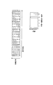
- the rust score is 4 and 5, and it is confirmed that no flaws are generated in the glass film.
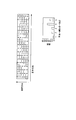
- the comparative example as shown in FIG. It is judged that the glass film is wrinkled in many places, and the steel plate steel is exposed.
- the surface of the glass coating on which the glass coating on which the compressive stress is applied is similarly irradiated to the surface of the glass coating. It was confirmed that the generation of soot was suppressed. Further, the generation of wrinkles was examined using a fiber laser or the like as the laser light to be irradiated, and similar results were obtained as a tendency. From the above, according to the example of the present invention, it was confirmed that generation of wrinkles in the glass film can be suppressed even under the same laser irradiation conditions.
- a high-quality unidirectional electrical steel sheet in which generation of wrinkles in a glass film is suppressed by irradiating a laser beam onto a surface on which a glass film on which compressive stress is applied is formed.
Landscapes
- Chemical & Material Sciences (AREA)
- Engineering & Computer Science (AREA)
- Physics & Mathematics (AREA)
- Mechanical Engineering (AREA)
- Organic Chemistry (AREA)
- Metallurgy (AREA)
- Materials Engineering (AREA)
- Manufacturing & Machinery (AREA)
- Crystallography & Structural Chemistry (AREA)
- Thermal Sciences (AREA)
- Electromagnetism (AREA)
- Dispersion Chemistry (AREA)
- Power Engineering (AREA)
- Manufacturing Of Steel Electrode Plates (AREA)
Abstract
Description
また、最終仕上焼鈍工程では、鋼板地鉄をコイル状に巻いた状態でバッチ式炉を用いて熱処理を行っている。このため、最終仕上焼鈍工程における鋼板地鉄の焼き付きを防止するために、最終仕上焼鈍工程の前に、鋼板地鉄の表面にマグネシア(MgO)を主体とする焼鈍分離剤を塗布している。
そして、最終仕上焼鈍工程においては、シリカを主体とする酸化物層とマグネシアを主体とする焼鈍分離剤とが反応することにより、上述のグラス皮膜が形成される。
そこで、レーザ照射工程において、最終仕上焼鈍工程時におけるコイルの径方向外側を向く面、すなわち、圧縮応力が作用したグラス皮膜に対してレーザビームを照射することにより、グラス皮膜における疵の発生を抑制することが可能となる。これにより、レーザ照射工程後に、再度、絶縁皮膜を形成する必要がなく、一方向性電磁鋼板の生産効率を大幅に向上することができる。
鋼板地鉄11(地鉄)は、Siを含有する鉄合金で構成されている。本実施形態では、Si;2.5質量%以上4.0質量%以下、C;0.02質量%以上0.10質量%以下、Mn;0.05質量%以上0.20質量%以下、酸可溶性Al;0.020質量%以上0.040質量%以下、N;0.002質量%以上0.012質量%以下、S;0.001質量%以上0.010質量%以下、P;0.01質量%以上0.04質量%以下、残部がFe及び不可避不純物、といった組成とされている。
また、鋼板地鉄11(地鉄)の厚さは、一般的に0.15mm以上0.35mm以下とされている。
本実施形態である一方向性電磁鋼板の製造方法は、図2のフロー図に示すように、鋳造工程S01と、熱間圧延工程S02と、焼鈍工程S03と、冷間圧延工程S04と、脱炭焼鈍工程S05と、焼鈍分離剤塗布工程S06と、最終仕上焼鈍工程S07と、絶縁皮膜形成工程S08と、レーザ照射工程S09と、を有している。
熱間圧延工程S02では、得られた鋳塊を所定温度(例えば1150~1400℃)に加熱して熱間圧延を実施する。これにより、たとえば厚さ1.8~3.5mmの熱間圧延材を製出する。
冷間圧延工程S04では、焼鈍工程S03後の熱間圧延材の表面を酸洗した上で、冷間圧延を実施する。これにより、たとえば厚さ0.15~0.35mmの冷間圧延材を製出する。
焼鈍分離剤塗布工程S06では、図3の○で囲んだ鋼板の断面拡大図に示すように、酸化物層15の上に、マグネシア(MgO)を主体とする焼鈍分離剤16を塗布する。
また、グラス皮膜12に疵の発生が少ない高品質の一方向性電磁鋼板10を提供することができる。
まず、Si;3.0質量%、C;0.05質量%、Mn;0.1質量%、酸可溶性Al;0.02質量%、N;0.01質量%、S;0.01質量%、P;0.02質量%、残部がFe及び不可避不純物、といった組成のスラブを準備した。
このスラブに対して、1280℃で熱間圧延を実施し、厚さ2.3mmの熱間圧延材を製出した。
この冷間圧延材に対して、800℃×2分の条件で脱炭焼鈍を実施した。そして、脱炭焼鈍後の冷間圧延材の両面に、マグネシアを主成分とする焼鈍分離材を塗布した。
次に、グラス皮膜の上に、リン酸アルミニウムからなる絶縁材を塗布、焼付け(850℃×1分)し、絶縁皮膜を形成した。
比較例では、最終仕上焼鈍時においてコイルの径方向内側を向く面に対してレーザビームを照射した。
評点5 合格、錆発生なし、レーザ照射部が目視確認できない。顕微鏡でも確認できない。
評点4 合格、錆発生なし、レーザ照射部が顕微鏡で確認される。目視では確認できない。
評点3 合格、錆発生なし、レーザ照射部が目視確認できる。(絶縁皮膜は、変質・損傷している可能性があるが、グラス皮膜は健全であり、絶縁性が維持されている状態)
評点2 不合格、錆発生あり、目視で離散的に錆を確認。
評点1 不合格、錆発生あり、目視で連続的に錆を確認。
なお、評点が4以上であれば、絶縁皮膜の再塗布を実施する必要がない。評価結果を、図7及び図8に示す。
一方、比較例においては、図8に示すように、錆評点が1,2,3となる箇所がある。多くの箇所でグラス皮膜に疵が発生し、鋼板地鉄が露出していると判断される。
なお、上記の実施例以外の前述した他のグラス皮膜や絶縁皮膜でも、同様に圧縮応力が作用しているグラス皮膜が形成されている面に対してレーザビームを照射することにより、グラス皮膜における疵の発生が抑制されることを確認した。さらに、照射するレーザ光として、ファイバーレーザ等を用いて疵の発生を調べて、傾向として同様の結果を得た。
以上のことから、本発明例によれば、同一のレーザ照射条件であっても、グラス皮膜における疵の発生を抑制可能であることが確認された。
11 鋼板地鉄
12 グラス皮膜
13 絶縁皮膜
S07 最終仕上焼鈍工程
S09 レーザ照射工程
Claims (1)
- 鋼板地鉄と、この鋼板地鉄の表面に形成されたグラス皮膜と、グラス皮膜の上に形成された絶縁皮膜と、を有する一方向性電磁鋼板の製造方法であって、
前記鋼板地鉄をコイル状に巻き取った状態でバッチ式炉において焼鈍を行い、前記鋼板地鉄の表面にグラス皮膜を形成する最終仕上焼鈍工程と、
前記最終仕上焼鈍工程の後に、前記グラス皮膜の上に絶縁皮膜を形成する絶縁皮膜形成工程と、
前記絶縁皮膜の上からレーザビームを照射し、磁区制御を行うレーザ照射工程と、を有し、
前記レーザ照射工程では、前記最終仕上焼鈍工程時におけるコイルの径方向外側を向く面に対して、レーザビームを照射することを特徴とする一方向性電磁鋼板の製造方法。
Priority Applications (4)
| Application Number | Priority Date | Filing Date | Title |
|---|---|---|---|
| PCT/JP2011/063475 WO2012172624A1 (ja) | 2011-06-13 | 2011-06-13 | 一方向性電磁鋼板の製造方法 |
| CN201180071308.XA CN103562418B (zh) | 2011-06-13 | 2011-06-13 | 单向性电磁钢板的制造方法 |
| BR112013030922-9A BR112013030922B1 (pt) | 2011-06-13 | 2011-06-13 | Método para fabricar folha de aço magnética de grão orientado |
| KR1020137030925A KR20130140213A (ko) | 2011-06-13 | 2011-06-13 | 일방향성 전자 강판의 제조 방법 |
Applications Claiming Priority (1)
| Application Number | Priority Date | Filing Date | Title |
|---|---|---|---|
| PCT/JP2011/063475 WO2012172624A1 (ja) | 2011-06-13 | 2011-06-13 | 一方向性電磁鋼板の製造方法 |
Publications (1)
| Publication Number | Publication Date |
|---|---|
| WO2012172624A1 true WO2012172624A1 (ja) | 2012-12-20 |
Family
ID=47356651
Family Applications (1)
| Application Number | Title | Priority Date | Filing Date |
|---|---|---|---|
| PCT/JP2011/063475 Ceased WO2012172624A1 (ja) | 2011-06-13 | 2011-06-13 | 一方向性電磁鋼板の製造方法 |
Country Status (4)
| Country | Link |
|---|---|
| KR (1) | KR20130140213A (ja) |
| CN (1) | CN103562418B (ja) |
| BR (1) | BR112013030922B1 (ja) |
| WO (1) | WO2012172624A1 (ja) |
Cited By (6)
| Publication number | Priority date | Publication date | Assignee | Title |
|---|---|---|---|---|
| WO2017171013A1 (ja) * | 2016-03-31 | 2017-10-05 | 新日鐵住金株式会社 | 方向性電磁鋼板 |
| WO2020158732A1 (ja) * | 2019-01-28 | 2020-08-06 | 日本製鉄株式会社 | 方向性電磁鋼板及びその製造方法 |
| RU2776383C1 (ru) * | 2019-01-28 | 2022-07-19 | Ниппон Стил Корпорейшн | Лист анизотропной электротехнической стали и способ его производства |
| WO2022203088A1 (ja) * | 2021-03-26 | 2022-09-29 | 日本製鉄株式会社 | 方向性電磁鋼板及びその製造方法 |
| JPWO2022203087A1 (ja) * | 2021-03-26 | 2022-09-29 | ||
| CN117043363A (zh) * | 2021-03-26 | 2023-11-10 | 日本制铁株式会社 | 方向性电磁钢板及其制造方法 |
Families Citing this family (2)
| Publication number | Priority date | Publication date | Assignee | Title |
|---|---|---|---|---|
| KR101904308B1 (ko) * | 2016-12-22 | 2018-10-04 | 주식회사 포스코 | 방향성 전기강판용 절연피막 조성물 및 이를 이용한 절연피막 형성방법, 방향성 전기강판 및 방향성 전기강판의 제조 방법 |
| EP3654356A1 (de) * | 2018-11-16 | 2020-05-20 | Siemens Aktiengesellschaft | Gedrucktes elektroblech |
Citations (3)
| Publication number | Priority date | Publication date | Assignee | Title |
|---|---|---|---|---|
| JPS57192223A (en) * | 1981-05-19 | 1982-11-26 | Nippon Steel Corp | Treatment of electromagnetic steel sheet |
| JPS6046325A (ja) * | 1984-05-07 | 1985-03-13 | Nippon Steel Corp | 電磁鋼板の処理方法 |
| JP2000109961A (ja) * | 1998-10-06 | 2000-04-18 | Nippon Steel Corp | 磁気特性の優れた一方向性電磁鋼板とその製造方法 |
Family Cites Families (1)
| Publication number | Priority date | Publication date | Assignee | Title |
|---|---|---|---|---|
| JP5008855B2 (ja) * | 2005-10-26 | 2012-08-22 | 新日本製鐵株式会社 | 磁気特性の優れた一方向性電磁鋼板の製造方法 |
-
2011
- 2011-06-13 CN CN201180071308.XA patent/CN103562418B/zh active Active
- 2011-06-13 WO PCT/JP2011/063475 patent/WO2012172624A1/ja not_active Ceased
- 2011-06-13 BR BR112013030922-9A patent/BR112013030922B1/pt active IP Right Grant
- 2011-06-13 KR KR1020137030925A patent/KR20130140213A/ko not_active Ceased
Patent Citations (3)
| Publication number | Priority date | Publication date | Assignee | Title |
|---|---|---|---|---|
| JPS57192223A (en) * | 1981-05-19 | 1982-11-26 | Nippon Steel Corp | Treatment of electromagnetic steel sheet |
| JPS6046325A (ja) * | 1984-05-07 | 1985-03-13 | Nippon Steel Corp | 電磁鋼板の処理方法 |
| JP2000109961A (ja) * | 1998-10-06 | 2000-04-18 | Nippon Steel Corp | 磁気特性の優れた一方向性電磁鋼板とその製造方法 |
Cited By (24)
| Publication number | Priority date | Publication date | Assignee | Title |
|---|---|---|---|---|
| JPWO2017171013A1 (ja) * | 2016-03-31 | 2019-01-10 | 新日鐵住金株式会社 | 方向性電磁鋼板 |
| RU2699344C1 (ru) * | 2016-03-31 | 2019-09-04 | Ниппон Стил Корпорейшн | Электротехнический стальной лист с ориентированной зеренной структурой |
| US10662491B2 (en) | 2016-03-31 | 2020-05-26 | Nippon Steel Corporation | Grain-oriented electrical steel sheet |
| WO2017171013A1 (ja) * | 2016-03-31 | 2017-10-05 | 新日鐵住金株式会社 | 方向性電磁鋼板 |
| JP7230933B2 (ja) | 2019-01-28 | 2023-03-01 | 日本製鉄株式会社 | 方向性電磁鋼板及びその製造方法 |
| WO2020158732A1 (ja) * | 2019-01-28 | 2020-08-06 | 日本製鉄株式会社 | 方向性電磁鋼板及びその製造方法 |
| JPWO2020158732A1 (ja) * | 2019-01-28 | 2021-11-25 | 日本製鉄株式会社 | 方向性電磁鋼板及びその製造方法 |
| RU2776383C1 (ru) * | 2019-01-28 | 2022-07-19 | Ниппон Стил Корпорейшн | Лист анизотропной электротехнической стали и способ его производства |
| CN117043363A (zh) * | 2021-03-26 | 2023-11-10 | 日本制铁株式会社 | 方向性电磁钢板及其制造方法 |
| RU2823712C2 (ru) * | 2021-03-26 | 2024-07-29 | Ниппон Стил Корпорейшн | Лист анизотропной электротехнической стали и способ его производства |
| JPWO2022203088A1 (ja) * | 2021-03-26 | 2022-09-29 | ||
| JPWO2022203087A1 (ja) * | 2021-03-26 | 2022-09-29 | ||
| WO2022203088A1 (ja) * | 2021-03-26 | 2022-09-29 | 日本製鉄株式会社 | 方向性電磁鋼板及びその製造方法 |
| RU2819013C2 (ru) * | 2021-03-26 | 2024-05-08 | Ниппон Стил Корпорейшн | Лист анизотропной электротехнической стали и способ его производства |
| US20240177899A1 (en) * | 2021-03-26 | 2024-05-30 | Nippon Steel Corporation | Grain-oriented electrical steel sheet and method for manufacturing same |
| WO2022203087A1 (ja) * | 2021-03-26 | 2022-09-29 | 日本製鉄株式会社 | 方向性電磁鋼板及びその製造方法 |
| EP4317469A4 (en) * | 2021-03-26 | 2024-08-07 | Nippon Steel Corporation | GRAIN-ORIENTED ELECTROMAGNETIC STEEL SHEET AND MANUFACTURING METHOD THEREFOR |
| EP4317468A4 (en) * | 2021-03-26 | 2024-08-07 | Nippon Steel Corporation | GRAIN-ORIENTED ELECTROMAGNETIC STEEL SHEET AND METHOD FOR PRODUCING THE SAME |
| JP7610157B2 (ja) | 2021-03-26 | 2025-01-08 | 日本製鉄株式会社 | 方向性電磁鋼板及びその製造方法 |
| EP4317470A4 (en) * | 2021-03-26 | 2025-02-26 | Nippon Steel Corporation | Grain-oriented electrical steel sheet and method for manufacturing same |
| JP7737027B2 (ja) | 2021-03-26 | 2025-09-10 | 日本製鉄株式会社 | 方向性電磁鋼板及びその製造方法 |
| US12424360B2 (en) * | 2021-03-26 | 2025-09-23 | Nippon Steel Corporation | Grain-oriented electrical steel sheet and method for manufacturing same |
| US12512240B2 (en) | 2021-03-26 | 2025-12-30 | Nippon Steel Corporation | Grain-oriented electrical steel sheet and method for manufacturing same |
| CN117043363B (zh) * | 2021-03-26 | 2026-03-31 | 日本制铁株式会社 | 方向性电磁钢板及其制造方法 |
Also Published As
| Publication number | Publication date |
|---|---|
| BR112013030922A2 (pt) | 2016-12-06 |
| CN103562418A (zh) | 2014-02-05 |
| KR20130140213A (ko) | 2013-12-23 |
| BR112013030922B1 (pt) | 2020-03-10 |
| CN103562418B (zh) | 2015-05-06 |
Similar Documents
| Publication | Publication Date | Title |
|---|---|---|
| JP7248917B2 (ja) | 方向性電磁鋼板及び方向性電磁鋼板の製造方法 | |
| KR101570017B1 (ko) | 방향성 전기 강판 및 그 제조 방법 | |
| CN103562418B (zh) | 单向性电磁钢板的制造方法 | |
| RU2580778C2 (ru) | Способ изготовления плоского изделия из электротехнической стали и плоское изделие из электротехнической стали | |
| RU2578296C2 (ru) | Текстурированный лист из электротехнической стали и способ снижения потерь в железе | |
| JP5229432B1 (ja) | 方向性電磁鋼板及び方向性電磁鋼板の製造方法 | |
| CN103429767B (zh) | 用于制造晶粒取向的钢板产品的方法 | |
| JP6044642B2 (ja) | レーザ加工装置及びレーザ照射方法 | |
| JP7393623B2 (ja) | 方向性電磁鋼板 | |
| US12173377B2 (en) | Grain-oriented electrical steel sheet and method for manufacturing same | |
| RU2771318C1 (ru) | Способ производства листа электротехнической стали с ориентированной зеренной структурой | |
| JP5906654B2 (ja) | 方向性電磁鋼板の製造方法 | |
| JP7511484B2 (ja) | 方向性電磁鋼板およびその製造方法 | |
| JP6003197B2 (ja) | 磁区細分化処理方法 | |
| JP7031364B2 (ja) | 方向性電磁鋼板の製造方法 | |
| JPWO2016002036A1 (ja) | レーザ加工装置 | |
| RU2767356C1 (ru) | Способ производства листа электротехнической стали с ориентированной зеренной структурой | |
| JP5928607B2 (ja) | 方向性電磁鋼板及び方向性電磁鋼板の製造方法 | |
| JP6003321B2 (ja) | 方向性電磁鋼板の製造方法 | |
| JP6881581B2 (ja) | 方向性電磁鋼板 | |
| JPWO2012172624A1 (ja) | 一方向性電磁鋼板の製造方法 | |
| RU2768094C1 (ru) | Способ производства листа электротехнической стали с ориентированной зеренной структурой | |
| JP2007308770A (ja) | 低鉄損方向性電磁鋼板およびその製造方法 | |
| RU2771315C1 (ru) | Способ производства листа электротехнической стали с ориентированной зеренной структурой | |
| WO2024111642A1 (ja) | 方向性電磁鋼板及びその製造方法 |
Legal Events
| Date | Code | Title | Description |
|---|---|---|---|
| ENP | Entry into the national phase |
Ref document number: 2011543746 Country of ref document: JP Kind code of ref document: A |
|
| 121 | Ep: the epo has been informed by wipo that ep was designated in this application |
Ref document number: 11867956 Country of ref document: EP Kind code of ref document: A1 |
|
| ENP | Entry into the national phase |
Ref document number: 20137030925 Country of ref document: KR Kind code of ref document: A |
|
| NENP | Non-entry into the national phase |
Ref country code: DE |
|
| REG | Reference to national code |
Ref country code: BR Ref legal event code: B01A Ref document number: 112013030922 Country of ref document: BR |
|
| 122 | Ep: pct application non-entry in european phase |
Ref document number: 11867956 Country of ref document: EP Kind code of ref document: A1 |
|
| ENP | Entry into the national phase |
Ref document number: 112013030922 Country of ref document: BR Kind code of ref document: A2 Effective date: 20131129 |