WO2012169281A1 - エネルギーデグレーダ、及びそれを備えた荷電粒子線照射システム - Google Patents
エネルギーデグレーダ、及びそれを備えた荷電粒子線照射システム Download PDFInfo
- Publication number
- WO2012169281A1 WO2012169281A1 PCT/JP2012/059585 JP2012059585W WO2012169281A1 WO 2012169281 A1 WO2012169281 A1 WO 2012169281A1 JP 2012059585 W JP2012059585 W JP 2012059585W WO 2012169281 A1 WO2012169281 A1 WO 2012169281A1
- Authority
- WO
- WIPO (PCT)
- Prior art keywords
- energy
- attenuation
- charged particle
- degrader
- particle beam
- Prior art date
- Legal status (The legal status is an assumption and is not a legal conclusion. Google has not performed a legal analysis and makes no representation as to the accuracy of the status listed.)
- Ceased
Links
Images


Classifications
-
- G—PHYSICS
- G21—NUCLEAR PHYSICS; NUCLEAR ENGINEERING
- G21K—HANDLING OF PARTICLES OR IONISING RADIATION NOT OTHERWISE PROVIDED FOR; IRRADIATION DEVICES; GAMMA RAY OR X-RAY MICROSCOPES
- G21K1/00—Arrangements for handling particles or ionising radiation, e.g. focusing or moderating
- G21K1/10—Scattering devices; Absorbing devices; Ionising radiation filters
-
- A—HUMAN NECESSITIES
- A61—MEDICAL OR VETERINARY SCIENCE; HYGIENE
- A61N—ELECTROTHERAPY; MAGNETOTHERAPY; RADIATION THERAPY; ULTRASOUND THERAPY
- A61N5/00—Radiation therapy
- A61N5/10—X-ray therapy; Gamma-ray therapy; Particle-irradiation therapy
- A61N5/1042—X-ray therapy; Gamma-ray therapy; Particle-irradiation therapy with spatial modulation of the radiation beam within the treatment head
-
- A—HUMAN NECESSITIES
- A61—MEDICAL OR VETERINARY SCIENCE; HYGIENE
- A61N—ELECTROTHERAPY; MAGNETOTHERAPY; RADIATION THERAPY; ULTRASOUND THERAPY
- A61N5/00—Radiation therapy
- A61N5/10—X-ray therapy; Gamma-ray therapy; Particle-irradiation therapy
- A61N5/1048—Monitoring, verifying, controlling systems and methods
-
- A—HUMAN NECESSITIES
- A61—MEDICAL OR VETERINARY SCIENCE; HYGIENE
- A61N—ELECTROTHERAPY; MAGNETOTHERAPY; RADIATION THERAPY; ULTRASOUND THERAPY
- A61N5/00—Radiation therapy
- A61N5/10—X-ray therapy; Gamma-ray therapy; Particle-irradiation therapy
- A61N2005/1085—X-ray therapy; Gamma-ray therapy; Particle-irradiation therapy characterised by the type of particles applied to the patient
- A61N2005/1087—Ions; Protons
-
- A—HUMAN NECESSITIES
- A61—MEDICAL OR VETERINARY SCIENCE; HYGIENE
- A61N—ELECTROTHERAPY; MAGNETOTHERAPY; RADIATION THERAPY; ULTRASOUND THERAPY
- A61N5/00—Radiation therapy
- A61N5/10—X-ray therapy; Gamma-ray therapy; Particle-irradiation therapy
- A61N2005/1092—Details
- A61N2005/1095—Elements inserted into the radiation path within the system, e.g. filters or wedges
Definitions
- the present invention relates to an energy degrader that attenuates the energy of a charged particle beam and a charged particle beam irradiation system including the same.
- Equipment for treating cancer by irradiating a patient with a charged particle beam such as a proton beam is known.
- This kind of equipment includes a cyclotron (accelerator) that accelerates ions (charged particles) generated by an ion source, a transport line that transports charged particles accelerated by the cyclotron, and a charged particle beam from any direction with respect to the patient.
- a cyclotron acceleration
- ions charged particles generated by an ion source
- transport line that transports charged particles accelerated by the cyclotron
- a charged particle beam from any direction with respect to the patient Is provided with a rotatable irradiation device (rotating gantry).
- Patent Document 1 discloses a degrader that attenuates beam energy by inserting a beam absorber (attenuating material) into a beam line (transport line).
- the energy of the charged particle beam is adjusted according to the irradiation position (depth) of the irradiated object.
- An energy degrader having an attenuating material is used to adjust the energy of the charged particle beam.
- the material of the damping material graphite that is not easily activated and inexpensive is used.
- the amount of energy to be attenuated is adjusted by changing the length of transmission of the charged particle beam in the attenuation material made of the same material.
- An object of the present invention is to solve the above problems, and an energy degrader capable of alleviating a decrease in transmittance of a charged particle beam having a lower energy, and a charged particle beam irradiation system including the energy degrader.
- the purpose is to provide.
- the present invention is an energy degrader provided with a plurality of attenuation members that attenuate the energy of the incident charged particle beam, and has a plurality of attenuation members with different amounts of energy to be attenuated, and the energy amount to be attenuated is larger.
- the low energy side attenuating member which is an attenuating member, is characterized in that it is made of a material having a higher charged particle beam transmittance than the high energy side attenuating member, which is the attenuating member having a smaller amount of energy to be attenuated.
- the energy degrader according to the present invention includes a plurality of attenuation members having different energy attenuation amounts, and the low energy side attenuation member having a larger energy attenuation amount is higher than the high energy side attenuation member having a smaller energy attenuation amount. Since it is made of a material having a high transmittance, it is possible to mitigate a decrease in the transmittance of the charged particle beam on the low energy side. As a result, in the low energy region (for example, 70 MeV or less), it is possible to suppress a decrease in the number of charged particles that pass through the attenuation member. When the energy attenuation amount is large, the energy of the charged particle beam after passing through the attenuation member is lower than when the energy attenuation amount is small.
- only the low energy side attenuation member having the largest amount of energy to attenuate may be made of a material having a high transmittance.
- only the attenuation member having the largest energy attenuation can be made to have a higher transmittance than the other attenuation members.
- the low energy side damping member can be made of beryllium, and the high energy side damping member can be made of graphite.
- beryllium as the low energy side attenuation member, the number of charged particles that pass through the attenuation member can be increased in the low energy region.
- the present invention also includes a charged particle beam irradiation system that includes the energy degrader and irradiates a charged particle beam, wherein the energy is accelerated by the accelerator that accelerates charged particles introduced into the energy degrader, and the energy degrader. And an irradiation device for irradiating the attenuated charged particle beam.
- the charged particle irradiation system includes an energy degrader that attenuates the energy of an incident charged particle beam.
- this energy degrader a plurality of attenuation members having different energy attenuation amounts are provided, and the low energy side attenuation member having a larger energy attenuation amount has a transmittance higher than the high energy side attenuation member having a smaller energy attenuation amount. Since it is formed of a high material, the transmittance of the charged particle beam on the low energy side can be improved. As a result, the number of charged particles that pass through the attenuation member can be increased in the low energy region.
- the energy degrader of the present invention and the charged particle beam irradiation system including the energy degrader, it is possible to alleviate a decrease in the transmittance of the charged particle beam having the lower energy, and the charged particles that pass through the low energy side attenuation member Can be suppressed.
- FIG. 1 is a layout view of a particle beam therapy system according to an embodiment of the present invention. It is the schematic which shows the energy degrader which concerns on embodiment of this invention. It is the schematic which shows the energy degrader which concerns on 2nd Example of this invention. It is the schematic which shows the energy degrader which concerns on 3rd Example of this invention. It is the schematic which shows the energy degrader which concerns on 4th Example of this invention.
- the particle beam therapy system is applied to cancer treatment, for example, and is a device that irradiates a tumor (irradiation target) in a patient's body with a proton beam (charged particle beam).
- a particle beam therapy system 1 includes a cyclotron (particle accelerator) 2 that generates a proton beam by accelerating ions (hydrogen cations) generated by an ion source (not shown), and a patient.
- a rotating gantry (irradiation device) 3 that irradiates a proton beam from an arbitrary direction with respect to the gantry 3 and a transport line that transports a proton beam (charged particle beam accelerated by the cyclotron) generated by the cyclotron 2 to the rotating gantry 3 4 is provided.
- the proton beam accelerated by the cyclotron 2 is deflected along the transport line 4 and transported to the rotating gantry 3.
- the transport line 4 is provided with a deflecting magnet for deflecting the proton beam.
- the transport line 4 is provided with an energy degrader 10 that attenuates the energy of charged particles (details will be described later).
- an ESS (energy selection system) 30 is provided in the transport line 4 at the subsequent stage (downstream) of the energy degrader 10.
- the ESS 30 selectively extracts a proton beam having a desired energy width from a proton beam having a predetermined energy distribution that has been transported.
- the energy width of the proton beam is selected to be in a desired range.
- the rotating gantry 3 includes a treatment table on which a patient lies and an irradiation unit that irradiates a proton beam toward the patient.
- the charged particle beam whose energy has been attenuated by the energy degrader 10 is emitted from the irradiation unit and irradiated onto the target site of the patient.
- FIG. 2 is a schematic diagram illustrating an energy degrader according to an embodiment of the present invention.
- the energy degrader 10 shown in FIG. 2 is provided on the path of the proton beam B (on the beam line) and attenuates the energy of the proton beam B.
- the energy degrader 10 includes a plurality of attenuation members 11A to 11G that attenuate the energy of the transmitted proton beam B. When it is not necessary to distinguish the attenuation members 11A to 11G, they are referred to as attenuation members 11.
- Attenuation members 11 having different thicknesses are arranged in one direction in order of thickness.
- the thickness here means the length in the transmission direction of the charged particle beam.
- the attenuation member 11 is arranged such that end faces on the exit side from which the proton beam B is emitted are aligned, and end faces on the opposite entrance side are arranged in a stepped shape.
- the attenuation member 11 does not need to be arrange
- the damping member 11 is integrally supported by a support member (not shown).
- the energy degrader 10 includes a drive source (for example, a drive motor) that applies a driving force to the attenuation member 11, guide means (for example, a guide rail) that guides the movement of the attenuation member 11, and the like. Then, the energy degrader 10 changes the attenuation amount of the energy of the proton beam B by moving the attenuation member 11 that transmits the proton beam B on the path of the proton beam B. The energy degrader 10 decelerates the proton beam B at a different deceleration depending on the thickness of the attenuation member 11 through which the proton beam B is transmitted. The proton beam B is attenuated with decreasing kinetic energy.
- a drive source for example, a drive motor
- guide means for example, a guide rail
- the low energy side attenuation member which is the attenuation member 11 with the larger amount of energy to attenuate
- the high energy side attenuation member which is the attenuation member 11 with the smaller amount of energy to attenuate.
- It is made of a material having a high transmittance of the beam B.
- a substance having a smaller atomic number is employed for the low energy side attenuation member than for the high energy side attenuation member. This is because as the atomic number of the attenuating material is larger, the scattering of the proton beam B is more widely spread, so the number of protons that can be transmitted is reduced.
- the attenuation member 11G having the largest amount of energy to be attenuated is formed of a material having a higher transmittance than the other attenuation members 11A to 11F.
- the material of the attenuation member 11 include carbon (C) and beryllium (Be).
- beryllium which is a stable solid material having a small atomic number, is employed for the attenuation member 11G on the lowest energy side, and carbon (graphite) is employed for the other attenuation members 11A to 11F.
- a material having higher transmittance than the remaining attenuation members 11A to 11E may be adopted for the two attenuation members 11G and 11F on the low energy side. Further, a material having a high transmittance may not be used for the attenuation member 11G on the lowest energy side. For example, a material having higher transmittance than the remaining attenuation members 11A to 11E is adopted for the attenuation member 11F on the low energy side, and the attenuation member 11G and the attenuation members 11A to 11D on the lowest energy side are formed of the same material. May be.
- the proton beam B is accelerated by the cyclotron 2, and the accelerated proton beam B (for example, having an energy range of 230 MeV ⁇ several MeV) is introduced into the energy degrader 10.
- the attenuation member 11 is driven and moved by the driving means, and the desired attenuation member 11 is disposed on the path of the proton beam B.
- the proton beam B that has passed through the attenuation member 11 is decelerated by the attenuation member 11 and the energy is attenuated (for example, 200 MeV ⁇ ten MeV).
- the proton beam B that has passed through the energy degrader 10 is introduced into the ESS 30.
- the proton beam B having a desired energy range is selectively extracted from the introduced proton beam B (for example, 200 MeV ⁇ 1 MeV).
- the proton beam B having the selected energy width is transported by the transport line 4 and introduced into the rotating gantry 3 to irradiate the irradiated object. Thereby, the proton beam B is irradiated so as to reach a predetermined depth position inside the irradiated body.
- the attenuation by the energy degrader 10 is reduced to reach a shallow position inside the irradiated body (for example, near the body surface).
- the attenuation amount is set larger than that of the energy degrader 10.
- the low energy side attenuation member 11G having the larger energy attenuation amount is formed of a material having a higher transmittance than the high energy side attenuation member having the smaller energy attenuation amount.
- the decrease in the transmittance of the proton beam B can be mitigated.
- scattering of the proton beam B can be suppressed, and a decrease in the number of protons that can pass through the attenuation member 11 can be suppressed.
- only the low energy side attenuation member 11G having the largest amount of energy to be attenuated is formed of beryllium having a high transmittance and low energy while suppressing an increase in manufacturing cost.
- a decrease in the number of protons that pass through the side attenuation member 11G can be suppressed. That is, a decrease in the number of irradiated protons can be suppressed.
- the proton beam B can be effectively irradiated to a shallow position near the body surface, and the highly reliable particle beam therapy system 1 can be realized.
- Table 1 below shows the transmittance of each energy of the proton beam B.
- the transmittance in Table 1 is a value measured at the outlet of ESS30.
- the material of the damping member at this time is the same and is made of graphite.
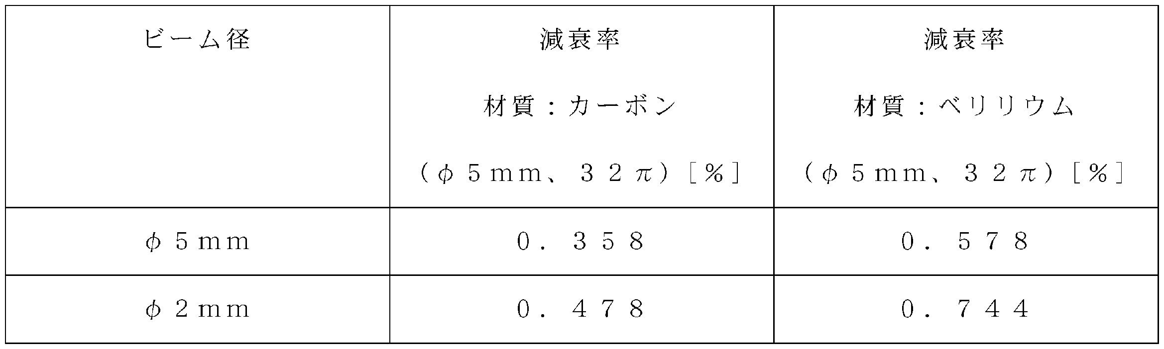
- Table 2 shows a comparison of the transmittance of the proton beam B depending on the material of the attenuation member. Measurement was performed for the case where the energy of the proton beam B was 70 [MeV] and the beam diameters were ⁇ 5 mm and ⁇ 2 mm.
- the energy degrader 10B shown in FIG. 3 is different from the energy degrader 10 shown in FIG. 2 in that the damping members 12A to 12G have different thicknesses. As described above, one damping member 12A to 12G may have a plurality of thicknesses.
- the energy degrader 10 ⁇ / b> C includes a pair of attenuation members 13 and 14 that are arranged to face each other.
- the damping member 11 has a wedge shape, and the inclined surfaces 13a and 14a are arranged facing each other.
- the attenuation members 13 and 14 are configured to be movable in the X direction intersecting the traveling direction of the proton beam B.
- the attenuation members 13 and 14 are moved in the X direction, and the length of the proton beam B passing through the attenuation members 13 and 14 is changed to control the attenuation amount of the energy of the proton beam B.
- the attenuating members 13 and 14 include a plurality of attenuating members 13A, 13B, 14A, and 14B having different amounts of energy to be attenuated.
- the low energy side attenuation members 13B and 14B having a larger amount of energy to be attenuated are formed of a material having a higher transmittance of the proton beam B than the high energy side attenuation members 13A and 14A having a smaller amount of energy to be attenuated.
- a material having high transmittance (beryllium) is used only in a portion where the energy of the proton beam B is attenuated to 70 [MeV].
- FIG. 5 is a front view of the energy degrader and is shown from the traveling direction of the proton beam B.
- the energy degrader 10D shown in FIG. 5 includes a plurality of attenuation members 15A and 15B having different thicknesses, and the plurality of attenuation members 15A and 15 are arranged in a spiral shape.
- the plurality of attenuation members 15A and 15B are arranged so that the center side is thin and the outside is thick.
- a plurality of attenuation members 15A and 15B may be arranged so that the center side is thick and the outside is thin.
- a rotating shaft 16 extending in parallel with the traveling direction of the proton beam B is disposed.
- the rotating shaft 16 is configured to be rotatable about the axis and movable in a direction intersecting with the traveling direction of the proton beam. As the rotary shaft 16 rotates and moves in a predetermined direction, desired attenuation members 15A and 15B are arranged on the proton beam path.
- the low energy side attenuation member 15B having the larger amount of energy to be attenuated is more proton beam than the high energy side attenuation member 15A having the smaller amount of energy to be attenuated. Is made of a material having a high transmittance.
- the scattering of the proton beam B is suppressed, and the protons transmitted through the attenuation members 13B and 14B are suppressed. The decrease in the number can be suppressed.
- the arrangement of the energy degrader 10 is not limited to the position immediately after the cyclotron 2, and the energy degrader 10 may be provided in the irradiation nozzle installed in the rotating gantry 3.
- the accelerator is not limited to the cyclotron 2 and may be another accelerator such as a synchrocyclotron.
- the charged particle beam is not limited to a proton beam, and may be a carbon beam (heavy particle beam) or the like.
- the material of the low energy side attenuation member is not limited to beryllium, and other attenuation materials may be adopted.
- the particle treatment system 1 may be fixed irradiation without using the rotating gantry.
- the energy degrader of the present invention and the charged particle beam irradiation system including the energy degrader can alleviate a decrease in the transmittance of the charged particle beam having the lower energy, and the number of charged particles that pass through the low energy side attenuation member. Can be suppressed.
- SYMBOLS 1 Particle beam therapy system (charged particle irradiation system), 2 ... Cyclotron (particle accelerator), 3 ... Rotating gantry, 4 ... Transport line, 10, 10B, 10C, 10D ... Energy degrader, 11A-11F, 12A-12F , 13A, 14A, 15A ... high energy side attenuation member (attenuation member), 11G, 12G, 13B, 14B, 15B ... low energy side attenuation member (attenuation member), B ... proton beam (charged particle beam).
Landscapes
- Health & Medical Sciences (AREA)
- Engineering & Computer Science (AREA)
- Biomedical Technology (AREA)
- Physics & Mathematics (AREA)
- General Health & Medical Sciences (AREA)
- Radiology & Medical Imaging (AREA)
- Life Sciences & Earth Sciences (AREA)
- Animal Behavior & Ethology (AREA)
- Nuclear Medicine, Radiotherapy & Molecular Imaging (AREA)
- Public Health (AREA)
- Veterinary Medicine (AREA)
- Pathology (AREA)
- Spectroscopy & Molecular Physics (AREA)
- General Engineering & Computer Science (AREA)
- High Energy & Nuclear Physics (AREA)
- Radiation-Therapy Devices (AREA)
Abstract
本発明は、エネルギーが低い方の荷電粒子線の透過率の低下を緩和することが可能なエネルギーデグレーダ(10)及びそれを備えた荷電粒子線照射システムを提供する。エネルギーの減衰量が異なる複数の減衰部材(11A~11G)を備え、エネルギー減衰量が大きい方の低エネルギー側減衰部材(11G)を、エネルギー減衰量が小さい方の高エネルギー側減衰部材(11A)よりも透過率が高い材質から形成する。
Description
本発明は、荷電粒子線のエネルギーを減衰させるエネルギーデグレーダ、及びそれを備えた荷電粒子線照射システムに関する。
陽子ビームなどの荷電粒子線を患者に照射してがん治療を行う設備が知られている。この種の設備は、イオン源で生成されたイオン(荷電粒子)を加速させるサイクロトロン(加速器)、サイクロトロンで加速された荷電粒子を輸送する輸送ライン、及び患者に対して任意の方向から荷電粒子線を照射する回転自在の照射装置(回転ガントリ)を備えている。
下記特許文献1に記載の技術では、ビームライン(輸送ライン)にビーム吸収体(減衰材)を挿入してビームエネルギーを減衰させるデグレーダが開示されている。
従来の荷電粒子線照射システムでは、被照射体の照射位置(深さ)に応じて荷電粒子線のエネルギーを調整している。荷電粒子線のエネルギーの調整には、減衰材を有するエネルギーデグレーダが用いられている。一般的に減衰材の材質としては、放射化しにくく、安価なグラファイトが採用されている。従来技術では、同一の材質からなる減衰材において、荷電粒子線が透過する長さを変更することで、減衰させるエネルギー量を調整していた。
また、近年、通常よりも低いエネルギーの荷電粒子線の使用要求が高まっている。エネルギーの減衰量を大きくするために減衰材を厚くすると、荷電粒子線の散乱が大きくなり、減衰材を透過可能な荷電粒子の数(=透過率)が減少することになる。
本発明は、以上の課題を解決することを目的としており、エネルギーが低い方の荷電粒子線の透過率の低下を緩和することが可能なエネルギーデグレーダ及びそれを備えた荷電粒子線照射システムを提供することを目的とする。
本発明は、入射した荷電粒子線のエネルギーを減衰させる複数の減衰部材を備えたエネルギーデグレーダであって、減衰させるエネルギー量が異なる複数の減衰部材を有し、減衰させるエネルギー量が大きい方の減衰部材である低エネルギー側減衰部材は、減衰させるエネルギー量が小さい方の減衰部材である高エネルギー側減衰部材よりも荷電粒子線の透過率が高い材質からなることを特徴としている。
本発明にかかるエネルギーデグレーダでは、エネルギーの減衰量が異なる複数の減衰部材を備え、エネルギー減衰量が大きい方の低エネルギー側減衰部材が、エネルギー減衰量が小さい方の高エネルギー側減衰部材よりも透過率が高い材質から形成されているため、低エネルギー側の荷電粒子線の透過率の低下を緩和することができる。その結果、低エネルギー領域(例えば70MeV以下)において、減衰部材を透過する荷電粒子数の減少を抑制することができる。エネルギー減衰量が大きい場合には、エネルギー減衰量が小さい場合と比較して、減衰部材を透過した後の荷電粒子線のエネルギーが低くなる。
また、複数の減衰部材のうち、減衰させるエネルギー量が最も大きい低エネルギー側減衰部材のみが、透過率が高い材質からなる構成としてもよい。このように、エネルギーの減衰量が最も大きい減衰部材のみを、他の減衰部材よりも透過率が高いものとすることができる。
また、低エネルギー側減衰部材は、ベリリウムから形成され、高エネルギー側減衰部材は、グラファイトから形成することができる。このように低エネルギー側減衰部材として、ベリリウムを採用することで、低エネルギー領域において、減衰部材を透過する荷電粒子数を増加させることができる。
また、本発明は、上記のエネルギーデグレーダを備え、荷電粒子線を照射する荷電粒子線照射システムであって、エネルギーデグレーダに導入される荷電粒子を加速する加速器と、エネルギーデグレーダによってエネルギーが減衰された荷電粒子線を照射する照射装置と、を備えることを特徴としている。
本発明に係る荷電粒子照射システムは、入射した荷電粒子線のエネルギーを減衰させるエネルギーデグレーダを備えている。このエネルギーデグレーダでは、エネルギーの減衰量が異なる複数の減衰部材を備え、エネルギー減衰量が大きい方の低エネルギー側減衰部材が、エネルギー減衰量が小さい方の高エネルギー側減衰部材よりも透過率が高い材質から形成されているため、低エネルギー側の荷電粒子線の透過率を向上させることができる。その結果、低エネルギー領域において、減衰部材を透過する荷電粒子数を増加させることができる。
本発明のエネルギーデグレーダ及びそれを備えた荷電粒子線照射システムによれば、エネルギーが低い方の荷電粒子線の透過率の低下を緩和することができ、低エネルギー側減衰部材を透過する荷電粒子の数の減少を抑制することが可能である。
以下、本発明に係るエネルギーデグレーダ、及びそれを備えた荷電粒子線照射システムの好適な実施形態について図面を参照しながら説明する。本実施形態では、荷電粒子線照射システムを粒子線治療システムとした場合について説明する。
(荷電粒子線照射システム)
粒子線治療システムは、例えばがん治療に適用されるものであり、患者の体内の腫瘍(照射目標物)に対して、陽子ビーム(荷電粒子線)を照射する装置である。
粒子線治療システムは、例えばがん治療に適用されるものであり、患者の体内の腫瘍(照射目標物)に対して、陽子ビーム(荷電粒子線)を照射する装置である。
図1に示すように、粒子線治療システム1は、イオン源(図示せず)にて生成されたイオン(水素の陽イオン)を加速させて陽子ビームを生成するサイクロトロン(粒子加速器)2、患者に対して任意の方向から陽子ビームを照射する回転自在の回転ガントリ(照射装置)3、サイクロトロン2で生成された陽子ビーム(サイクロトロンで加速された荷電粒子ビーム)を回転ガントリ3まで輸送する輸送ライン4を備えている。
サイクロトロン2で加速された陽子ビームは、輸送ライン4に沿って偏向され、回転ガントリ3に輸送される。輸送ライン4には、陽子ビームを偏向させるための偏向磁石が設けられている。また、輸送ライン4には、荷電粒子のエネルギーを減衰させるエネルギーデグレーダ10が設けられている(詳しくは後述する)。
更に、輸送ライン4には、エネルギーデグレーダ10の後段(下流)に、ESS(エネルギー選択システム)30が設けられている。このESS30は、輸送されてきた所定のエネルギー分布を有する陽子ビームから所望のエネルギー幅の陽子ビームを選択的に取り出すものである。ESS30では、陽子ビームのエネルギー幅が、所望の範囲となるように選択される。
回転ガントリ3は、患者が横たわる治療台、患者に向けて陽子ビームを照射する照射部を備えている。エネルギーデグレーダ10によってエネルギーが減衰された荷電粒子線は、照射部から出射され、患者の対象部位に照射される。
(エネルギーデグレーダ)
図2は、本発明の実施形態に係るエネルギーデグレーダを示す概略図である。図2に示すエネルギーデグレーダ10は、陽子ビームBの経路上(ビームライン上)に設けられ、陽子ビームBのエネルギーを減衰させるものである。エネルギーデグレーダ10は、透過する陽子ビームBのエネルギーを減衰させる複数の減衰部材11A~11Gを備えている。なお、減衰部材11A~11Gを区別する必要がないときは、減衰部材11と記す。
図2は、本発明の実施形態に係るエネルギーデグレーダを示す概略図である。図2に示すエネルギーデグレーダ10は、陽子ビームBの経路上(ビームライン上)に設けられ、陽子ビームBのエネルギーを減衰させるものである。エネルギーデグレーダ10は、透過する陽子ビームBのエネルギーを減衰させる複数の減衰部材11A~11Gを備えている。なお、減衰部材11A~11Gを区別する必要がないときは、減衰部材11と記す。
エネルギーデグレーダ10では、互いに厚さが異なる減衰部材11が、一方向に厚さ順に配置されている。本実施形態では、陽子ビームBの経路と交差する方向Xにおいて、減衰部材11Aから減衰部材11Gへ順に厚さが増加するように配置されている。なお、ここでいう厚さとは、荷電粒子線の透過方向における長さをいう。減衰部材11は、例えば、陽子ビームBが出射される出口側の端面が揃うように配置され、反対の入口側の端面が階段状を成すように配置されている。なお、減衰部材11は、厚さ順に配置されていなくてもよい。また、出口側の端面が階段状を成すように配置されていてもよく、その他の配置でもよい。
減衰部材11は、支持部材(不図示)によって一体的に支持されている。また、エネルギーデグレーダ10は、減衰部材11に駆動力を付与する駆動源(例えば、駆動モータ)、減衰部材11の移動を案内する案内手段(例えば、ガイドレール)など備えている。そして、エネルギーデグレーダ10は、陽子ビームBを透過させる減衰部材11を、陽子ビームBの経路上に移動させることで、陽子ビームBのエネルギーの減衰量を変更する。エネルギーデグレーダ10は、陽子ビームBが透過する減衰部材11の厚さに応じて異なる減速度で陽子ビームBを減速させる。陽子ビームBは、運動エネルギーが減少して減衰する。
ここで、エネルギーデグレーダ10では、減衰させるエネルギー量が大きい方の減衰部材11である低エネルギー側減衰部材が、減衰させるエネルギー量が小さい方の減衰部材11である高エネルギー側減衰部材よりも陽子ビームBの透過率が高い材質から形成されている。換言すれば、高エネルギー側減衰部材よりも、低エネルギー側減衰部材に、原子番号が小さい物質が採用されている。これは、減衰材料の原子番号が大きいほど陽子ビームBの散乱が大きく広がるため、透過できる陽子の数が減ることによる。
本実施形態のエネルギーデグレーダ10では、減衰させるエネルギー量が最も大きい減衰部材11Gのみが、その他の減衰部材11A~11Fよりも透過率が高い材質から形成されている。減衰部材11の材質としては、例えば、炭素(C)、ベリリウム(Be)などが挙げられる。本実施形態では、最も低エネルギー側の減衰部材11Gに、原子番号が小さい安定固形物質であるベリリウムが採用され、その他の減衰部材11A~11Fに炭素(グラファイト)が採用されている。
なお、低エネルギー側の二つの減衰部材11G,11Fに、残りの減衰部材11A~11Eよりも透過率が高い材質を採用してもよい。また、最も低エネルギー側の減衰部材11Gに透過率が高い材質を採用しない場合でもよい。例えば、低エネルギー側の減衰部材11Fに、残りの減衰部材11A~11Eよりも透過率が高い材質を採用し、最も低エネルギー側の減衰部材11Gと減衰部材11A~11Dとを同じ材質によって形成してもよい。
(エネルギーデグレーダ及び粒子線治療システムの作用)
粒子線治療システム1では、サイクロトロン2によって陽子ビームBが加速され、加速された陽子ビームB(例えば230MeV±数MeVのエネルギー範囲を有する)は、エネルギーデグレーダ10に導入される。エネルギーデグレーダ10では、駆動手段によって減衰部材11が駆動されて移動し、陽子ビームBの経路上に所望の減衰部材11が配置されている。そして、この減衰部材11を通過した陽子ビームBは、減衰部材11によって減速されて、エネルギーが減衰させられる(例えば200MeV±十数MeV)。
粒子線治療システム1では、サイクロトロン2によって陽子ビームBが加速され、加速された陽子ビームB(例えば230MeV±数MeVのエネルギー範囲を有する)は、エネルギーデグレーダ10に導入される。エネルギーデグレーダ10では、駆動手段によって減衰部材11が駆動されて移動し、陽子ビームBの経路上に所望の減衰部材11が配置されている。そして、この減衰部材11を通過した陽子ビームBは、減衰部材11によって減速されて、エネルギーが減衰させられる(例えば200MeV±十数MeV)。
エネルギーデグレーダ10を通過した陽子ビームBは、ESS30に導入される。ESS30では、導入された陽子ビームBうち、所望のエネルギー範囲の陽子ビームBが選択的に取り出される(例えば200MeV±1MeV)。エネルギー幅が選択された陽子ビームBは、輸送ライン4によって輸送されて回転ガントリ3に導入されて、被照射体に照射される。これにより、被照射体の内部の所定の深さ位置に到達するように陽子ビームBが照射される。被照射体の内部の深い位置に到達するように陽子ビームBを照射する場合には、エネルギーデグレーダ10による減衰量を小さくし、被照射体の内部の浅い位置(例えば体表付近)に到達するように陽子ビームBを照射する場合には、エネルギーデグレーダ10より減衰量を大きくする。
このような本実施形態のエネルギーデグレーダ及びそれを備えた粒子線治療システムによれば、複数の減衰部材11を備え、これらの減衰部材11に入射する陽子ビームBのエネルギーを減衰させることができる。エネルギーデグレーダ10では、エネルギー減衰量が大きい方の低エネルギー側減衰部材11Gが、エネルギー減衰量が小さい方の高エネルギー側減衰部材よりも透過率が高い材料から形成されているため、低エネルギー側の陽子ビームBの透過率の低下を緩和することができる。その結果、低エネルギー領域において、陽子ビームBの散乱を抑え、減衰部材11を透過できる陽子の数の減少を抑制することができる。
また、複数の減衰部材11のうち、減衰させるエネルギー量が最も大きい低エネルギー側減衰部材11Gのみが、透過率が高く高価なベリリウムによって形成されているため、製造コストの増加を抑えつつ、低エネルギー側減衰部材11Gを透過する陽子の数の減少を抑制することができる。すなわち、照射される陽子の数の減少を抑制することができる。これにより、体表付近の浅い位置へ、有効に陽子ビームBを照射することができ、信頼性の高い粒子線治療システム1を実現することができる。
下記の表1は、陽子ビームBの各エネルギーにおける透過率を示すものである。表1中の透過率は、ESS30の出口で測定した値である。このときの減衰部材の材質は、全て同一でありグラファイトをしている。

下記の表2は、陽子ビームBの透過率について、減衰部材の材質による比較を示すものである。陽子ビームBのエネルギーが70[MeV]であり、ビーム径がφ5mm、φ2mmである場合について計測した。
(第2実施例)
次に図3を参照して、第2実施例に係るエネルギーデグレーダ10Bについて説明する。図3に示すエネルギーデグレーダ10Bが、図2に示すエネルギーデグレーダ10と違う点は、一つの減衰部材12A~12Gにおいて、異なる厚さを有する点である。このように一つの減衰部材12A~12Gにおいて、複数の厚みを有する構成としてもよい。
次に図3を参照して、第2実施例に係るエネルギーデグレーダ10Bについて説明する。図3に示すエネルギーデグレーダ10Bが、図2に示すエネルギーデグレーダ10と違う点は、一つの減衰部材12A~12Gにおいて、異なる厚さを有する点である。このように一つの減衰部材12A~12Gにおいて、複数の厚みを有する構成としてもよい。
(第3実施例)
次に図4を参照して、第3実施例に係るエネルギーデグレーダ10Cについて説明する。図4に示すように、エネルギーデグレーダ10Cは、互いに対向して配置された一対の減衰部材13,14を有している。減衰部材11は、くさび形を成し、互いの斜面13a,14a同士が対面して配置されている。減衰部材13,14は、陽子ビームBの進行方向と交差するX方向に移動可能な構成とされている。減衰部材13,14をX方向に移動させ、陽子ビームBが減衰部材13,14を透過する長さを変更して、陽子ビームBのエネルギーの減衰量を制御する。なお、減衰部材13,14の何れか一方を、陽子ビームBの進行方向へ駆動して、減衰部材13,14の隙間を調整し、陽子ビームBのビーム径を制御する構成としてもよい。
次に図4を参照して、第3実施例に係るエネルギーデグレーダ10Cについて説明する。図4に示すように、エネルギーデグレーダ10Cは、互いに対向して配置された一対の減衰部材13,14を有している。減衰部材11は、くさび形を成し、互いの斜面13a,14a同士が対面して配置されている。減衰部材13,14は、陽子ビームBの進行方向と交差するX方向に移動可能な構成とされている。減衰部材13,14をX方向に移動させ、陽子ビームBが減衰部材13,14を透過する長さを変更して、陽子ビームBのエネルギーの減衰量を制御する。なお、減衰部材13,14の何れか一方を、陽子ビームBの進行方向へ駆動して、減衰部材13,14の隙間を調整し、陽子ビームBのビーム径を制御する構成としてもよい。
この減衰部材13,14は、減衰させるエネルギー量が異なる複数の減衰部材13A,13B,14A,14Bを備えている。減衰させるエネルギー量が大きい方の低エネルギー側減衰部材13B,14Bは、減衰させるエネルギー量が小さい方の高エネルギー側減衰部材13A,14Aよりも、陽子ビームBの透過率が高い材質から形成されている。例えば、陽子ビームBのエネルギーを70[MeV]に減衰させる部分にのみ、透過率が高い材質(ベリリウム)が採用されている。
このような第3実施例のエネルギーデグレーダ10Cにおいても、上記実施形態のエネルギーデグレーダ10と同様に、低エネルギー領域において、陽子ビームBの散乱を抑え、減衰部材13B,14Bを透過する陽子の数の減少を抑制することができる。
(第4実施例)
次に図5を参照して、第4実施例に係るエネルギーデグレーダ10Dについて説明する。図5は、エネルギーデグレーダの正面図であり、陽子ビームBの進行方向から示すものである。図5に示すエネルギーデグレーダ10Dは、厚さが異なる複数の減衰部材15A,15Bを備え、複数の減衰部材15A,15は、渦巻き状に配置されている。例えば、中央側が薄く、外側が厚くなるように、複数の減衰部材15A,15Bが配置されている。なお、中央側が厚く、外側が薄くなるように複数の減衰部材15A,15Bを配置してもよい。
次に図5を参照して、第4実施例に係るエネルギーデグレーダ10Dについて説明する。図5は、エネルギーデグレーダの正面図であり、陽子ビームBの進行方向から示すものである。図5に示すエネルギーデグレーダ10Dは、厚さが異なる複数の減衰部材15A,15Bを備え、複数の減衰部材15A,15は、渦巻き状に配置されている。例えば、中央側が薄く、外側が厚くなるように、複数の減衰部材15A,15Bが配置されている。なお、中央側が厚く、外側が薄くなるように複数の減衰部材15A,15Bを配置してもよい。
エネルギーデグレーダ10Dの中央には、陽子ビームBの進行方向と平行に延在する回転軸16が配置されている。この回転軸16は、軸周りに回転可能であると共に、陽子ビームの進行方向と交差する方向に移動可能な構成とされている。この回転軸16が回転する共に、所定の方向に移動することで、所望の減衰部材15A,15Bが陽子ビームの経路上に配置される。
ここで、第4実施例のエネルギーデグレーダ10Dにおいても、減衰させるエネルギー量が大きい方の低エネルギー側減衰部材15Bは、減衰させるエネルギー量が小さい方の高エネルギー側減衰部材15Aよりも、陽子ビームの透過率が高い材質から形成されている。このような第4実施例のエネルギーデグレーダ10Dにおいても、上記実施形態のエネルギーデグレーダ10と同様に、低エネルギー領域において、陽子ビームBの散乱を抑え、減衰部材13B,14Bを透過する陽子の数の減少を抑制することができる。
以上、本発明をその実施形態に基づき具体的に説明したが、本発明は、上記実施形態に限定されるものではない。
また、エネルギーデグレーダ10の配置は、サイクロトロン2の直後に限定されず、回転ガントリ3に設置された照射ノズル中にエネルギーデグレーダ10が設けられている構成でもよい。
また、加速器は、サイクロトロン2に限定されず、例えば、シンクロサイクロトロンなど、他の加速器でもよい。また、荷電粒子線は陽子ビームに限定されず、炭素ビーム(重粒子ビーム)などでも良い。
また、低エネルギー側減衰部材の材質は、ベリリウムに限定されず、その他の減衰材料を採用してもよい。
また、粒子治療システム1は、回転ガントリを用いず、固定照射としてもよい。
本発明のエネルギーデグレーダ及びそれを備えた荷電粒子線照射システムは、エネルギーが低い方の荷電粒子線の透過率の低下を緩和することができ、低エネルギー側減衰部材を透過する荷電粒子の数の減少を抑制することが可能である。
1…粒子線治療システム(荷電粒子照射システム)、2…サイクロトロン(粒子加速器)、3…回転ガントリ、4…輸送ライン、10,10B,10C,10D…エネルギーデグレーダ、11A~11F,12A~12F,13A,14A,15A…高エネルギー側減衰部材(減衰部材)、11G,12G,13B,14B,15B…低エネルギー側減衰部材(減衰部材)、B…陽子ビーム(荷電粒子線)。
Claims (4)
- 入射した荷電粒子線のエネルギーを減衰させる複数の減衰部材を備えたエネルギーデグレーダであって、
減衰させるエネルギー量が異なる複数の前記減衰部材を有し、
減衰させるエネルギー量が大きい方の前記減衰部材である低エネルギー側減衰部材は、減衰させるエネルギー量が小さい方の前記減衰部材である高エネルギー側減衰部材よりも前記荷電粒子線の透過率が高い材質からなることを特徴とするエネルギーデグレーダ。 - 前記複数の減衰部材のうち、減衰させるエネルギー量が最も大きい前記低エネルギー側減衰部材のみが、前記透過率が高い材質からなることを特徴とする請求項1に記載のエネルギーデグレーダ。
- 前記低エネルギー側減衰部材は、ベリリウムから形成され、前記高エネルギー側減衰部材は、グラファイトから形成されていることを特徴とする請求項1又は2に記載のエネルギーデグレーダ。
- 請求項1~3の何れか一項に記載のエネルギーデグレーダを備え、前記荷電粒子線を照射する荷電粒子線照射システムであって、
前記エネルギーデグレーダに導入される荷電粒子を加速する加速器と、
前記エネルギーデグレーダによってエネルギーが減衰された前記荷電粒子線を照射する照射装置と、
を備える荷電粒子線照射システム。
Priority Applications (3)
| Application Number | Priority Date | Filing Date | Title |
|---|---|---|---|
| CN201280026887.0A CN103582915B (zh) | 2011-06-06 | 2012-04-06 | 降能器及具备该降能器的带电粒子束照射系统 |
| US14/098,026 US20140091238A1 (en) | 2011-06-06 | 2013-12-05 | Energy degrader and charged particle beam irradiation system equipped therewith |
| US14/607,658 US9390826B2 (en) | 2011-06-06 | 2015-01-28 | Energy degrader and charged particle beam irradiation system equipped therewith |
Applications Claiming Priority (2)
| Application Number | Priority Date | Filing Date | Title |
|---|---|---|---|
| JP2011-126342 | 2011-06-06 | ||
| JP2011126342A JP5726644B2 (ja) | 2011-06-06 | 2011-06-06 | エネルギーデグレーダ、及びそれを備えた荷電粒子線照射システム |
Related Child Applications (1)
| Application Number | Title | Priority Date | Filing Date |
|---|---|---|---|
| US14/098,026 Continuation US20140091238A1 (en) | 2011-06-06 | 2013-12-05 | Energy degrader and charged particle beam irradiation system equipped therewith |
Publications (1)
| Publication Number | Publication Date |
|---|---|
| WO2012169281A1 true WO2012169281A1 (ja) | 2012-12-13 |
Family
ID=47295852
Family Applications (1)
| Application Number | Title | Priority Date | Filing Date |
|---|---|---|---|
| PCT/JP2012/059585 Ceased WO2012169281A1 (ja) | 2011-06-06 | 2012-04-06 | エネルギーデグレーダ、及びそれを備えた荷電粒子線照射システム |
Country Status (5)
| Country | Link |
|---|---|
| US (2) | US20140091238A1 (ja) |
| JP (1) | JP5726644B2 (ja) |
| CN (1) | CN103582915B (ja) |
| TW (1) | TWI459405B (ja) |
| WO (1) | WO2012169281A1 (ja) |
Cited By (2)
| Publication number | Priority date | Publication date | Assignee | Title |
|---|---|---|---|---|
| JP2018004455A (ja) * | 2016-07-01 | 2018-01-11 | 株式会社東芝 | 重イオンビーム生成装置及び方法 |
| CN108325095A (zh) * | 2015-09-30 | 2018-07-27 | 南京中硼联康医疗科技有限公司 | 用于中子捕获治疗的射束整形体 |
Families Citing this family (22)
| Publication number | Priority date | Publication date | Assignee | Title |
|---|---|---|---|---|
| US20140264065A1 (en) * | 2013-03-15 | 2014-09-18 | Varian Medical Systems, Inc. | Energy degrader for radiation therapy system |
| US9962560B2 (en) | 2013-12-20 | 2018-05-08 | Mevion Medical Systems, Inc. | Collimator and energy degrader |
| US10675487B2 (en) * | 2013-12-20 | 2020-06-09 | Mevion Medical Systems, Inc. | Energy degrader enabling high-speed energy switching |
| WO2016035151A1 (ja) * | 2014-09-03 | 2016-03-10 | 三菱電機株式会社 | 可搬型線形加速器システムおよびそれを備えた可搬型中性子源 |
| ES2620670T3 (es) * | 2014-12-16 | 2017-06-29 | Ion Beam Applications S.A. | Degradador de energía |
| US10786689B2 (en) | 2015-11-10 | 2020-09-29 | Mevion Medical Systems, Inc. | Adaptive aperture |
| EP3174069A1 (en) * | 2015-11-27 | 2017-05-31 | Paul Scherrer Institut | Degrader comprising boron carbide |
| JP6748110B2 (ja) * | 2015-11-30 | 2020-08-26 | 株式会社カネカ | エネルギーデグレーダ、及びそれを備えた荷電粒子線照射システム |
| US10485993B2 (en) | 2016-03-01 | 2019-11-26 | Intraop Medical Corporation | Low energy electron beam radiation system that generates electron beams with precisely controlled and adjustable penetration depth useful for therapeutic applications |
| WO2017183697A1 (ja) | 2016-04-21 | 2017-10-26 | 株式会社カネカ | 放射性同位元素製造用の支持基板、放射性同位元素製造用ターゲット板、及び支持基板の製造方法 |
| WO2017188117A1 (ja) * | 2016-04-28 | 2017-11-02 | 株式会社カネカ | ビーム強度変換膜、及びビーム強度変換膜の製造方法 |
| WO2018009779A1 (en) | 2016-07-08 | 2018-01-11 | Mevion Medical Systems, Inc. | Treatment planning |
| CN106267585B (zh) * | 2016-07-29 | 2019-06-18 | 中国原子能科学研究院 | 一种用于粒子治疗的能量调制装置及其使用方法 |
| CN106304606A (zh) * | 2016-07-29 | 2017-01-04 | 中国原子能科学研究院 | 一种双直排插入式降能器及其使用方法 |
| CN106267584B (zh) * | 2016-07-29 | 2018-12-28 | 中国原子能科学研究院 | 一种双盘旋转式紧凑型降能器及其使用方法 |
| WO2018128822A1 (en) * | 2017-01-05 | 2018-07-12 | Mevion Medical Systems, Inc. | High-speed energy switching |
| WO2019006253A1 (en) | 2017-06-30 | 2019-01-03 | Mevion Medical Systems, Inc. | CONFIGURABLE COLLIMATOR CONTROLLED BY LINEAR MOTORS |
| CN109240200A (zh) * | 2018-11-21 | 2019-01-18 | 合肥中科离子医学技术装备有限公司 | 一种超导质子装置降能器控制系统 |
| WO2021050535A1 (en) | 2019-09-14 | 2021-03-18 | Intraop Medical Corporation | Methods and systems for using and controlling higher dose rate ionizing radiation in short time intervals |
| CN111741587A (zh) * | 2020-05-25 | 2020-10-02 | 中国原子能科学研究院 | 一种真空环境束流能量在线调节装置 |
| CN116943053B (zh) * | 2023-09-06 | 2024-06-07 | 广东省新兴激光等离子体技术研究院 | 粒子束剂量调节装置及其方法、放射治疗设备 |
| CN117858328A (zh) * | 2024-01-08 | 2024-04-09 | 中国科学院国家空间科学中心 | 一种用于质子加速器的质子束靶前快速降能机构 |
Citations (3)
| Publication number | Priority date | Publication date | Assignee | Title |
|---|---|---|---|---|
| JPH10270200A (ja) * | 1997-03-27 | 1998-10-09 | Mitsubishi Electric Corp | 出射ビーム強度制御装置及び制御方法 |
| JP2004313314A (ja) * | 2003-04-14 | 2004-11-11 | Hitachi Ltd | 粒子線照射装置及び荷電粒子ビームの照射方法 |
| JP2006142315A (ja) * | 2004-11-16 | 2006-06-08 | Kobe Steel Ltd | エネルギービーム加工装置,エネルギービーム加工方法 |
Family Cites Families (11)
| Publication number | Priority date | Publication date | Assignee | Title |
|---|---|---|---|---|
| JPH01286300A (ja) | 1988-05-12 | 1989-11-17 | Toshiba Corp | 加速器のビーム遮断装置 |
| JPH11142600A (ja) * | 1997-11-12 | 1999-05-28 | Mitsubishi Electric Corp | 荷電粒子線照射装置及び照射方法 |
| BE1012358A5 (fr) * | 1998-12-21 | 2000-10-03 | Ion Beam Applic Sa | Procede de variation de l'energie d'un faisceau de particules extraites d'un accelerateur et dispositif a cet effet. |
| JP4282198B2 (ja) | 2000-02-03 | 2009-06-17 | 株式会社東芝 | 粒子線照射装置 |
| EP1677254A1 (en) * | 2004-12-30 | 2006-07-05 | GSF-Forschungszentrum für Umwelt und Gesundheit GmbH | Method and device for collimating an energy input beam |
| JP2006280457A (ja) * | 2005-03-31 | 2006-10-19 | Hitachi Ltd | 荷電粒子ビーム出射装置及び荷電粒子ビーム出射方法 |
| JP4797140B2 (ja) * | 2007-01-18 | 2011-10-19 | 独立行政法人国立がん研究センター | 荷電粒子線照射装置 |
| US7801271B2 (en) * | 2007-12-23 | 2010-09-21 | Oraya Therapeutics, Inc. | Methods and devices for orthovoltage ocular radiotherapy and treatment planning |
| JP4691574B2 (ja) * | 2008-05-14 | 2011-06-01 | 株式会社日立製作所 | 荷電粒子ビーム出射装置及び荷電粒子ビーム出射方法 |
| GB2460089A (en) * | 2008-05-16 | 2009-11-18 | Elekta Ab | Coincident treatment and imaging source |
| US8269197B2 (en) * | 2009-07-22 | 2012-09-18 | Intraop Medical Corporation | Method and system for electron beam applications |
-
2011
- 2011-06-06 JP JP2011126342A patent/JP5726644B2/ja not_active Expired - Fee Related
-
2012
- 2012-04-06 WO PCT/JP2012/059585 patent/WO2012169281A1/ja not_active Ceased
- 2012-04-06 CN CN201280026887.0A patent/CN103582915B/zh not_active Expired - Fee Related
- 2012-04-23 TW TW101114378A patent/TWI459405B/zh not_active IP Right Cessation
-
2013
- 2013-12-05 US US14/098,026 patent/US20140091238A1/en not_active Abandoned
-
2015
- 2015-01-28 US US14/607,658 patent/US9390826B2/en not_active Expired - Fee Related
Patent Citations (3)
| Publication number | Priority date | Publication date | Assignee | Title |
|---|---|---|---|---|
| JPH10270200A (ja) * | 1997-03-27 | 1998-10-09 | Mitsubishi Electric Corp | 出射ビーム強度制御装置及び制御方法 |
| JP2004313314A (ja) * | 2003-04-14 | 2004-11-11 | Hitachi Ltd | 粒子線照射装置及び荷電粒子ビームの照射方法 |
| JP2006142315A (ja) * | 2004-11-16 | 2006-06-08 | Kobe Steel Ltd | エネルギービーム加工装置,エネルギービーム加工方法 |
Non-Patent Citations (1)
| Title |
|---|
| VLADIMIR ANFEROV: "Energy degrader optimization for medical beam lines", NUCLEAR INSTRUMENTS AND METHODS IN PHYSICS RESEARCH A, vol. 496, 2003, pages 222 - 227 * |
Cited By (2)
| Publication number | Priority date | Publication date | Assignee | Title |
|---|---|---|---|---|
| CN108325095A (zh) * | 2015-09-30 | 2018-07-27 | 南京中硼联康医疗科技有限公司 | 用于中子捕获治疗的射束整形体 |
| JP2018004455A (ja) * | 2016-07-01 | 2018-01-11 | 株式会社東芝 | 重イオンビーム生成装置及び方法 |
Also Published As
| Publication number | Publication date |
|---|---|
| US20140091238A1 (en) | 2014-04-03 |
| JP2012249940A (ja) | 2012-12-20 |
| TW201250709A (en) | 2012-12-16 |
| US9390826B2 (en) | 2016-07-12 |
| TWI459405B (zh) | 2014-11-01 |
| CN103582915B (zh) | 2016-03-16 |
| JP5726644B2 (ja) | 2015-06-03 |
| CN103582915A (zh) | 2014-02-12 |
| US20150170780A1 (en) | 2015-06-18 |
Similar Documents
| Publication | Publication Date | Title |
|---|---|---|
| JP5726644B2 (ja) | エネルギーデグレーダ、及びそれを備えた荷電粒子線照射システム | |
| JP5638606B2 (ja) | エネルギーデグレーダ、及びそれを備えた荷電粒子照射システム | |
| JP5748153B2 (ja) | 粒子線治療で使用するビーム分析器を備えるガントリ | |
| EP2612692B1 (en) | Neutron beam irradiation system | |
| US8822965B2 (en) | Charged particle beam irradiation apparatus | |
| JP5726541B2 (ja) | エネルギーデグレーダ、及びそれを備えた荷電粒子照射システム | |
| JP2012249940A5 (ja) | ||
| CN105163805B (zh) | 用于放射治疗系统的能量降能器 | |
| JP2016122001A (ja) | エネルギーディグレーダ | |
| EP3946581B1 (en) | Non-achromatic compact gantry | |
| JP2008264062A (ja) | レンジシフタ及び粒子線照射装置 | |
| JP6748110B2 (ja) | エネルギーデグレーダ、及びそれを備えた荷電粒子線照射システム | |
| JP2018196625A (ja) | 荷電粒子線治療装置 | |
| EP2990077B1 (en) | Particle beam treatment device | |
| JP3681382B2 (ja) | 粒子線照射装置及び荷電粒子ビーム照射装置の調整方法 | |
| WO2018181595A1 (ja) | 荷電粒子線治療装置 | |
| HK40009272A (en) | Energy degrader for radiation therapy system |
Legal Events
| Date | Code | Title | Description |
|---|---|---|---|
| WWE | Wipo information: entry into national phase |
Ref document number: 201280026887.0 Country of ref document: CN |
|
| 121 | Ep: the epo has been informed by wipo that ep was designated in this application |
Ref document number: 12796392 Country of ref document: EP Kind code of ref document: A1 |
|
| NENP | Non-entry into the national phase |
Ref country code: DE |
|
| 122 | Ep: pct application non-entry in european phase |
Ref document number: 12796392 Country of ref document: EP Kind code of ref document: A1 |