WO2012169247A1 - 受信器 - Google Patents
受信器 Download PDFInfo
- Publication number
- WO2012169247A1 WO2012169247A1 PCT/JP2012/055621 JP2012055621W WO2012169247A1 WO 2012169247 A1 WO2012169247 A1 WO 2012169247A1 JP 2012055621 W JP2012055621 W JP 2012055621W WO 2012169247 A1 WO2012169247 A1 WO 2012169247A1
- Authority
- WO
- WIPO (PCT)
- Prior art keywords
- peak
- counter
- signal
- spread signal
- receiver
- Prior art date
- Legal status (The legal status is an assumption and is not a legal conclusion. Google has not performed a legal analysis and makes no representation as to the accuracy of the status listed.)
- Ceased
Links
Images





Classifications
-
- H—ELECTRICITY
- H04—ELECTRIC COMMUNICATION TECHNIQUE
- H04B—TRANSMISSION
- H04B1/00—Details of transmission systems, not covered by a single one of groups H04B3/00 - H04B13/00; Details of transmission systems not characterised by the medium used for transmission
- H04B1/69—Spread spectrum techniques
- H04B1/707—Spread spectrum techniques using direct sequence modulation
- H04B1/7073—Synchronisation aspects
- H04B1/7075—Synchronisation aspects with code phase acquisition
Definitions
- the present invention relates to a receiver that detects the header of packet data from encoded received data and obtains data capture timing.
- a transmitter adds a header to packet data and transmits the packet data, and the receiver detects the header and obtains the packet data.
- header detection and packet data decoding are performed by symbol synchronization (for example, refer to Patent Documents 1 and 2).
- FIG. 5 is a schematic configuration diagram illustrating a symbol synchronization unit included in the receiver.
- the symbol synchronization unit includes a convolver (correlation detector) 50 that detects a correlation value from an input received signal, an absolute value output unit 51 that converts the detected correlation value into an absolute value, and an absolute value of the correlation value.
- a peak detector 52 that detects a peak by comparing with a threshold value, a symbol synchronizer 53 that determines header detection when the number of detected peaks exceeds a predetermined value, and a delay device 54 that delays a signal input from the convolver 50 , including.
- FIG. 6 is a flowchart showing the flow of symbol synchronization processing in the receiver shown in FIG.
- the data information spread by the spreading code in the transmitter is modulated and transmitted.
- the received signal is demodulated by the demodulator (step ST201).
- the demodulated signal detects a correlation value using the same spreading code (hereinafter referred to as a reference code) as the spreading code used by the convolver 50 on the transmitter side (step ST202).
- FIG. 7A shows a waveform of a correlation value output signal (referred to as a correlation signal) output from the convolver 50.
- the difference between the correlation signal output from the convolver 50 and the correlation signal after one symbol delay (FIG. 7B) is taken (step ST203), and the difference signal shown in FIG. A waveform is obtained (step ST204).
- the header information added to the packet data is a fixed value of 8 bits such as 01010000, for example, the difference signal obtained by the difference from the correlation signal after 1 symbol delay is 0 and 1 of both symbols.
- a peak appears at the overlapping timing (FIG. 7D).
- FIG. 7D a continuous peak output appears in a region surrounded by a one-dot chain line.
- the peak detector 52 compares the correlation value with the threshold value. If the correlation value exceeds the threshold value (step ST205: Yes), the peak detector 52 determines that the peak (maximum value) has been detected and counts. Increment the number.
- step ST206 If it is the said header information of 8 bits (01010000), when a peak is counted 4 times continuously (step ST206: Yes), it will judge that header information was detected (step ST207), and delay device 54 Packet data is taken in and decoded (step ST208).
- step ST205 when the peak value does not reach the threshold value (step ST205: No), or when the maximum value is not continuously counted four times within one symbol (step ST206: No), the header is not detected. Judgment is made (step ST209), and the packet data is discarded (step ST210).
- the threshold value is determined by adding the correlation value of the received symbol and the received symbol correlation value after one symbol delay. If the value level is low, the threshold may not be exceeded. As a result, there is a problem that packet data is discarded without detecting the header and packet loss occurs.
- the present invention has been made in view of such a point, and an object of the present invention is to provide a receiver capable of increasing a packet data acquisition rate by increasing a header detection rate in symbol synchronization of encoded information data.
- the receiver of the present invention generates a spread signal by multiplying information data including header information having a predetermined bit pattern on the transmitter side by a spread code of N bits (N is a natural number), and uses the spread signal to generate a carrier wave.
- An AD converter that outputs a spread signal sequence, and generates a reference code having an N ⁇ M bit length correlated with the spread code used to generate the spread signal on the transmitter side, and the reference code and the AD conversion
- a correlator for detecting a correlation value with an N ⁇ M bit length spread signal sequence output from the unit and shifting the spread signal sequence to be detected in the time-series direction in bit units, and a correlation value by the correlator Detected
- a counter that repeats a counter index that is a count number in a range of 1 to N
- this receiver it is possible to obtain a peak distribution obtained by accumulating the number of peak detections corresponding to the counter index, and if it can be determined from the peak distribution that the number of peaks corresponding to the number of symbols in the header information has been continuously detected, Since the header information has been detected, the timing for decoding the spread signal can be obtained. Thereby, even if the peak of the correlation output is low, the peak can be counted, so that the header can be detected. Therefore, even when the S / N ratio is small, it is possible to increase the header data detection rate in symbol synchronization and increase the packet data acquisition rate.
- the receiver can be used for a communication device that performs electric field communication of an information signal via a transmission medium.
- the present invention it is possible to increase the packet data acquisition rate by increasing the header detection rate in symbol synchronization.
- FIG. 1 is a schematic configuration diagram showing a communication system according to an embodiment of the present invention.
- the communication system shown in FIG. 1 includes a transmission medium 2 such as a human body that transmits information data via an electric field, a transmitter 1 that applies an electric field obtained by modulating information data to the transmission medium 2, and a transmission medium 2.
- the receiver 3 mainly detects the electric field and demodulates the electric field into information data.
- the transmitter 1 is disposed close to the transmission medium 2 and mainly includes a transmission electrode (not shown) that applies an electric field to the transmission medium 2 and a transmission circuit (not shown).
- the transmitter 1 generates a spread signal by multiplying information data including header information having a predetermined bit pattern by a spread code of N bits (N is a natural number), and a modulator 11 modulates a carrier wave with the spread signal. To transmit a transmission signal.
- the receiver 3 is disposed close to the transmission medium 2, receives a reception electrode (not shown) that receives an electric field from the transmission medium 2, a demodulator 31 that demodulates the received transmission signal and extracts a spread signal, and demodulated diffusion It includes an AD converter 32 that oversamples the signal M times (M is a natural number) and outputs a spread signal sequence, and a symbol synchronization unit 33 that decodes packet data.
- FIG. 2 is a schematic configuration diagram showing the symbol synchronization unit 33.
- the symbol synchronization unit 33 includes a convolver (correlator) 34, an index extractor 35, a peak distribution holding unit 36, a determination unit 37, and a delay unit 38.
- a convolver (correlator) 34 generates a reference code having an N ⁇ M bit length correlated with the spreading code used to generate the spread signal on the transmitter 1 side, and outputs the reference code and the N code output from the AD converter 32.
- a correlation value with a spread signal sequence of ⁇ M bit length is detected, and a spread signal sequence as a correlation detection target is shifted in the time series direction in bit units.
- the index extractor 35 detects the peak of the correlation value (absolute value) detected by the convolver 34 and outputs an index corresponding to the peak position.
- the peak distribution holding unit 36 has a free-run counter 361 that counts in synchronization with the index extracted by the index extractor 35 and repeats a counter index as a count number in a range of 1 to N ⁇ M, and is output from the convolver 34.
- a peak is detected from the correlation value, and the counter number corresponding to the counter index when the peak is detected is incremented. That is, the free-run counter 361 accumulates the number of detection times of the peak-detected counter index for each counter index.
- the determination unit 37 continuously determines the number of times corresponding to the number of symbols in the header information within the same counter index or the counter index range assumed to be the same from the cumulative distribution of the peak detection times accumulated in the peak distribution holding unit 36. If the peak is detected, a timing signal for decoding the spread signal extracted by the demodulator 31 is output.
- the determination unit 37 includes a maximum index determination unit 37a that determines the maximum counter index from the number of detections accumulated in the free-run counter 361, and a peak detection number of the counter index that is the maximum from the detection number. If the header information is a fixed value of 8 bits such as 01010000, the index determination unit 37b outputs a timing signal when it reaches 8 times.
- the delay unit 38 delays the reception signal input from the convolver 34 by a header (8 bits), and takes in the signal held when the timing signal is received from the index determination unit 37b as packet data.
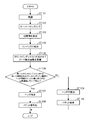
- FIG. 3 is a flowchart showing a flow of symbol synchronization processing in the receiver shown in FIGS.
- the information data spread by the transmitter 1 using the spread code is transmitted after being phase-modulated, for example, by the modulator 11.
- the demodulator 31 demodulates the received signal (step ST101).
- the AD converter 32 oversamples the demodulated extension signal M times (step ST102).
- the convolver 34 detects a correlation value using a reference code having a high correlation with the spreading code (step ST103).
- the index extractor 35 extracts an index corresponding to the peak position of the detected correlation value (step ST104).
- the peak distribution holding unit 36 accumulates the number of peak detections in association with 1 to N ⁇ M counter indexes (step ST105).
- the determination unit 37 determines the header information. It is determined that it has been detected (step ST107), and packet data is fetched from the delay unit 38 and decoded (step ST108).
- step ST106 if no peak is detected continuously for the number of times corresponding to the number of symbols in the header information (step ST106: No), it is determined that the header has not been detected.
- the packet data is discarded (step ST110).
- the header information added to the packet data is 8 bits
- the received signal received by the receiver 3 is demodulated by the demodulator 31.
- the demodulated extension signal is double-sampled by the AD converter 32, and the AD converter 32 outputs a 16-bit extended signal sequence.
- the index extractor 35 repeatedly counts in the range of 0 to 15 in synchronization with the bit shift of the extended signal sequence to be detected by the convolver 34, and outputs a counter index corresponding to the peak position of the correlation value.
- the peak distribution holding unit 36 counts the counter index extracted by the index extractor 35 in the free-run counter 361 in parallel, and accumulates the peak position detected from the correlation value output from the convolver 34 in correspondence with the counter index.
- the reason why the counter index in the free-run counter 361 is 16 bits long from 0 to 15 is that the spreading code is 8 bits, and the extension signal is double-sampled by the AD converter 32. By becoming an index data string.
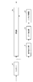
- FIG. 4A is a diagram illustrating an example of a correlation value peak for 8 symbols corresponding to the number of symbols in the header information and a counter index corresponding to the peak.
- the peak distribution holding unit 36 stores the number of peak detections at the counter index 7.
- the peak distribution holding unit 36 accumulates and stores the number of peak detections at the counter index 7. This is performed up to the eighth symbol.
- the peak distribution holding unit 36 accumulates and stores the number of peak detections at the counter index 7.
- the determination unit 37 the number of times corresponding to the number of symbols of the header information in the same counter index or the counter index range assumed to be the same from the cumulative distribution of the number of peak detections accumulated in the peak distribution holding unit 36. It is determined whether or not a peak has been detected for 8 consecutive times.
- FIG. 4B is a diagram illustrating an example of a cumulative distribution of the number of peak detections accumulated in the peak distribution holding unit 36.
- the vertical axis indicates the number of symbols
- the horizontal axis indicates the counter index where the peak is detected.
- the distribution range of the peak detection frequency for 8 symbols is shown, and the peak detection frequency is highest in the counter index 7, but peaks are also detected in the counter indexes 6 and 8.
- the counter index range is assumed to be the same if the distribution range is the median value ⁇ 1. Therefore, the example of FIG. 4B shows that peaks were detected eight times consecutively in the same counter index or a counter index range that is assumed to be the same.
- the distribution range of the median value of the counter index ⁇ 1 may straddle symbols. For example, when the median value of the counter index is 0, the distribution range of the median value ⁇ 1 of the counter index is 15, 0, 1 of the previous symbol. When the median value of the counter index is 15, the distribution range of the median value ⁇ 1 of the counter index is 14, 15 and 0 of the next symbol.
- the peak value of the correlation value is small, it is possible to count peaks that are continuous for 8 symbols. Therefore, even if the peak value of the correlation value decreases as the S / N ratio (Signal to Noise ratio) decreases due to the communication environment, the counter index for 8 symbols is determined and its distribution range is determined. It becomes possible.
- the convolver 34, the index extractor 35, and the free-run counter 361 can obtain the index together with the correlation output corresponding to the spread code, and the maximum index determination After determining the counter index having the maximum peak value from among these indexes by the unit 37a, the header in the received signal (packet data) is detected by determining the cumulative number of these counter indexes by the index determining unit 37b. can do. Thereby, even if the peak of the correlation output is low, the peak can be counted, so that the header can be detected. Therefore, even when the S / N ratio is small, it is possible to increase the header data detection rate in symbol synchronization and increase the packet data acquisition rate.
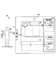
- FIG. 8 is a system configuration diagram of the electric field communication system according to the embodiment of the present invention.
- a transmission / reception apparatus that transmits and receives an information signal via a human body will be described as an example of a transmission medium.
- the present invention is not limited to this configuration, and can be changed as appropriate.
- the communication system 100 transmits and receives information signals via a transmission medium such as the human body 102, and is in contact with or capacitively coupled to the communication apparatus 103 attached to the human body 102.
- a transmission / reception device 104 that communicates with the communication device 103 via the human body 102 is provided.
- the receiver 3 is applied to the receivers of the communication device 103 and the transmission / reception device 104.
- the communication device 103 has substantially the same configuration as the transmission / reception device 104 and is different from the transmission / reception device 104 only in that the communication device 103 is worn on the human body 102. Therefore, in the following description, description of the communication device 103 is omitted as much as possible, and the description will focus on the transmission / reception device 104.
- the communication device 103 and the human body 102 and the transmission / reception device 104 and the human body 102 are electrically capacitively coupled, and the information signal is transmitted by an electric field obtained by modulating the information signal. It is like that. In this case, the displacement current flows through the human body 102 but the steady current does not flow. Therefore, the communication device 103 and the human body 102 do not need to be electrically connected. Therefore, for example, since the electrode of the communication device 103 and the human body 102 are capacitively coupled via a thin cloth, an information signal can be transmitted even from the top of clothing.
- the human body 102 is a transmission medium through which a displacement current flows, and has a high impedance of several hundreds [ ⁇ ], for example.
- the transmission / reception device 104 includes a transmission / reception electrode 111 that is in contact with or electrically capacitively coupled to the human body 102.
- a transmission system 112 that receives an information signal from the communication device 103 via the transmission / reception electrode 111 and a transmission system 113 that transmits an information signal to the communication device 103 via the transmission / reception electrode 111 are connected to the transmission / reception electrode 111, respectively.
- the transmission / reception electrode 111 is formed of a flat plate electrode, and can communicate with the communication device 103 via an electric field applied to the human body 102 by contact or capacitive coupling with the human body 102.
- the reception system 112 has a filter 122 connected to the transmission / reception electrode 111 via a coupling capacitor 121.
- a receiving unit 127 provided in the electric field communication IC 114 is connected to the subsequent stage of the filter 122 via a coupling capacitor 126.
- the receiving unit 127 includes a demodulation circuit (not shown), and demodulates the modulated signal received from the communication device 103 via the transmission / reception electrode 111 using the carrier wave used in the communication device 103 to obtain an information signal.
- the present invention can be applied not only to electric field communication systems but also to receivers in other data communication systems.
Landscapes
- Engineering & Computer Science (AREA)
- Computer Networks & Wireless Communication (AREA)
- Signal Processing (AREA)
- Synchronisation In Digital Transmission Systems (AREA)
Abstract
シンボル同期におけるヘッダの検出率を高めてパケットデータの取得率を上げること。受信器は、相関器(34)で相関値が検出されるのに同期してカウンタインデックスを1からN×Mの範囲で繰り返すカウンタ(361)を有し、相関器(34)から出力される相関値からピークを検出するとともに、1からN×Mのカウンタインデックスに対応させてピーク検出回数を累積するピーク分布保持部(36)と、ピーク分布保持部(36)に累積されたピーク検出回数の累積分布から、同一のカウンタインデックスまたは同一と擬制されるカウンタインデックス範囲で、ヘッダ情報のシンボル数に相当する回数だけ連続してピーク検出されたならば、復調部で取り出された拡散信号を復号するタイミングを生成する判定部(37)と、を具備する構成とする。
Description
本発明は、符号化された受信データの中からパケットデータのヘッダを検出してデータ取り込みタイミングを獲得する受信器に関する。
従来、電界通信システムにおいて、送信器側にてパケットデータにヘッダを付加して送信し、受信器側にて当該ヘッダを検出してパケットデータを取得している。このような電界通信システムでは、シンボル同期によって、ヘッダの検出およびパケットデータの復号化を行っている(例えば、特許文献1,2参照)。
従来の受信器におけるシンボル同期の手法について説明する。
図5は、受信器に備えるシンボル同期部を示す概略構成図である。このシンボル同期部は、入力された受信信号から相関値を検出するコンボルバ(相関検出器)50と、検出された相関値を絶対値に変換する絶対値出力器51と、相関値の絶対値と閾値とを比較してピークを検出するピーク検出器52と、検出ピーク数が所定値を超えたらヘッダ検出と判定するシンボル同期器53と、コンボルバ50から入力された信号を遅延させる遅延器54と、を含む。
図5は、受信器に備えるシンボル同期部を示す概略構成図である。このシンボル同期部は、入力された受信信号から相関値を検出するコンボルバ(相関検出器)50と、検出された相関値を絶対値に変換する絶対値出力器51と、相関値の絶対値と閾値とを比較してピークを検出するピーク検出器52と、検出ピーク数が所定値を超えたらヘッダ検出と判定するシンボル同期器53と、コンボルバ50から入力された信号を遅延させる遅延器54と、を含む。
図6は、図5に示す受信器におけるシンボル同期処理の流れを示すフローチャートである。送信器において拡散符号により拡散されたデータ情報は変調されて送信される。受信器側は、復調器によって受信信号を復調する(ステップST201)。復調信号は、コンボルバ50が送信器側で用いた拡散符号と同じ拡散符号(以下、参照符号という)を用いて相関値を検出する(ステップST202)。図7Aはコンボルバ50から出力される相関値の出力信号(相関信号という)波形を示す。コンボルバ50から出力される相関信号と、1シンボル遅延後の相関信号(図7B)との差分をとり(ステップST203)、図7Cに示す差分信号を絶対値出力器51に通して正極性のピーク波形を得る(ステップST204)。
パケットデータに付加されたヘッダ情報が、例えば01010000といった固定値の8ビットであるとすれば、1シンボル遅延後の相関信号との差分で得られる差分信号は、双方のシンボルのうち0と1が重なるタイミングでピークがあらわれる(図7D)。図7Dでは、1点鎖線で囲まれた領域に連続したピーク出力があらわれている。ピーク検出器52は、相関値としきい値とを比較して、相関値がしきい値を超えている場合には(ステップST205:Yes)、ピーク(最大値)を検出したと判断してカウント数をインクリメントする。そして、上記8ビット(01010000)のヘッダ情報であれば、ピークを4回連続してカウントした場合には(ステップST206:Yes)、ヘッダ情報を検出したと判断し(ステップST207)、遅延器54からパケットデータを取り込んで復号化する(ステップST208)。
一方、ピーク値がしきい値に達しない場合(ステップST205:No)、または、1シンボル内で、最大値を4回連続カウントしない場合(ステップST206:No)には、ヘッダを検出しなかったと判断し(ステップST209)、パケットデータは破棄される(ステップST210)。
しかしながら、上記シンボル同期の方法は、受信シンボルの相関値と1シンボル遅延後の受信シンボル相関値とを加算してしきい値判定するので、シンボル相関値でピークが現れたとしても通信環境によって相関値のレベルが低い場合には、しきい値を超えない可能性がある。その結果、ヘッダ検出されずに、破棄されるパケットデータが発生し、パケットロスが発生するという問題がある。
本発明は、かかる点に鑑みてなされたものであり、符号化された情報データのシンボル同期におけるヘッダの検出率を高めてパケットデータの取得率を上げることができる受信器を提供することを目的とする。
本発明の受信器は、送信器側において所定ビットパターンからなるヘッダ情報を含む情報データに対してNビット(Nは自然数)の拡散符号を掛けて拡散信号を生成し、該拡散信号で搬送波を変調して送信した送信信号を受信する受信器であって、受信した送信信号を復調して前記拡散信号を取り出す復調部と、前記復調された拡散信号をM倍(Mは自然数)にオーバーサンプリングして拡散信号系列を出力するAD変換部と、前記送信器側で拡散信号の生成に用いた拡散符号と相関のあるN×Mビット長の参照符号を生成し、当該参照符号と前記AD変換部から出力されるN×Mビット長の拡散信号系列との相関値を検出し、相関検出対象となる拡散信号系列をビット単位で時系列方向にシフトさせる相関器と、前記相関器で相関値が検出されるのに同期してカウントし、カウント数となるカウンタインデックスを1からN×Mの範囲で繰り返すカウンタを有し、前記相関器から出力される相関値からピークを検出し、1からN×Mのカウンタインデックスに対応させてピーク検出回数を累積するピーク分布保持部と、前記ピーク分布保持部に累積されたピーク検出回数の累積分布から、同一のカウンタインデックスまたは同一と擬制されるカウンタインデックス範囲で、前記ヘッダ情報のシンボル数に相当する回数だけ連続してピーク検出されたならば、前記復調部で取り出された拡散信号を復号するタイミングを生成する判定部と、具備したことを特徴とする。
この受信器によれば、カウンタインデックスに対応させてピーク検出回数を累積したピーク分布を得ることができ、ピーク分布からヘッダ情報のシンボル数に相当する回数だけ連続してピーク検出されたと判定できれば、ヘッダ情報を検出できたことになり、拡散信号を復号するタイミングを獲得できる。これにより、相関出力のピークが低い場合であっても、ピークをカウントすることができるため、ヘッダを検出することが可能となる。したがって、S/N比が小さい場合であっても、シンボル同期におけるヘッダの検出率を高めてパケットデータの取得率を上げることが可能となる。
また、上記受信器において、前記AD変換部は、M=2となるダブルサンプリングを行うようにしてもよい。
さらに、上記受信器は、伝送媒体を介して情報信号を電界通信する通信装置に用いることができる。
本発明によれば、シンボル同期におけるヘッダの検出率を高めてパケットデータの取得率を上げることができる。
以下、本発明の実施の形態について添付図面を参照して詳細に説明する。
図1は、本発明の実施の形態に係る通信システムを示す概略構成図である。図1に示す通信システムは、電界を介して情報データを伝送する人体などの伝送媒体2と、伝送媒体2に対して情報データを変調した電界を付与する送信器1と、伝送媒体2を介して電界を検出し、その電界を情報データに復調する受信器3とから主に構成されている。
図1は、本発明の実施の形態に係る通信システムを示す概略構成図である。図1に示す通信システムは、電界を介して情報データを伝送する人体などの伝送媒体2と、伝送媒体2に対して情報データを変調した電界を付与する送信器1と、伝送媒体2を介して電界を検出し、その電界を情報データに復調する受信器3とから主に構成されている。
送信器1は、伝送媒体2に近接配置しており、伝送媒体2に電界を与える図示しない送信電極と、図示しない送信回路とから主に構成される。送信器1は、所定ビットパターンからなるヘッダ情報を含む情報データに対してNビット(Nは自然数)の拡散符号を掛けて拡散信号を生成し、変調器11においてこの拡散信号で搬送波を変調して、送信信号を送信する。
受信器3は、伝送媒体2に近接配置しており、伝送媒体2からの電界を受ける図示しない受信電極と、受信した送信信号を復調して拡散信号を取り出す復調器31と、復調された拡散信号をM倍(Mは自然数)にオーバーサンプリングして拡散信号系列を出力するADコンバータ32と、パケットデータの復号化を行うシンボル同期部33と、を含む。
図2は、シンボル同期部33を示す概略構成図である。シンボル同期部33は、コンボルバ(相関器)34と、インデックス抽出器35と、ピーク分布保持部36と、判定部37と、遅延器38と、を含む。コンボルバ(相関器)34は、送信器1側で拡散信号の生成に用いた拡散符号と相関のあるN×Mビット長の参照符号を生成し、この参照符号とADコンバータ32から出力されるN×Mビット長の拡散信号系列との相関値を検出するとともに、相関検出対象となる拡散信号系列をビット単位で時系列方向にシフトさせる。インデックス抽出器35は、コンボルバ34の検出する相関値(絶対値)のピークを検出してピーク位置に対応したインデックスを出力する。ピーク分布保持部36は、インデックス抽出器35が抽出するインデックスに同期してカウントし、カウント数となるカウンタインデックスを1からN×Mの範囲で繰り返すフリーランカウンタ361を有し、コンボルバ34から出力される相関値からピークを検出し、ピークが検出された時のカウンタインデックスに対応したカウンタ数をインクリメントする。すなわち、フリーランカウンタ361には、ピーク検出されたカウンタインデックスの検出回数がカウンタインデックスごとに累積される。判定部37は、ピーク分布保持部36に累積されたピーク検出回数の累積分布から、同一のカウンタインデックスまたは同一と擬制されるカウンタインデックス範囲で、ヘッダ情報のシンボル数に相当する回数だけ連続してピーク検出されたならば、復調器31で取り出された拡散信号を復号するタイミング信号を出力する。判定部37は、フリーランカウンタ361に累積された検出回数から最大となるカウンタインデックスを判定する最大インデックス判定器37aと、検出回数から最大となるカウンタインデックスのピーク検出回数がしきい値(例えば、ヘッダ情報が01010000といった固定値の8ビットであるとすれば、8回)に到達したらタイミング信号を出力するインデックス判定器37bとを有する。遅延器38は、コンボルバ34から入力される受信信号をヘッダ(8ビット)分遅延させ、インデックス判定器37bからタイミング信号を受けた時に保持している信号をパケットデータとして取り込む。
続いて、本発明の実施の形態に係る受信器におけるシンボル同期の手法について説明する。
図3は、図1,2に示す受信器におけるシンボル同期処理の流れを示すフローチャートである。送信器1において拡散符号により拡散された情報データは、変調器11において例えば位相変調されて送信される。受信器3側は、復調器31によって受信信号を復調する(ステップST101)。ADコンバータ32は、復調された拡張信号をM倍にオーバーサンプリングする(ステップST102)。コンボルバ34は、拡散符号と相関の高い参照符号を用いて相関値を検出する(ステップST103)。インデックス抽出器35は、検出された相関値のピーク位置に対応したインデックスを抽出する(ステップST104)。ピーク分布保持部36は、1からN×Mのカウンタインデックスに対応させてピーク検出回数を累積する(ステップST105)。判定部37は、同一のカウンタインデックスまたは同一と擬制されるカウンタインデックス範囲で、ヘッダ情報のシンボル数に相当する回数だけ連続してピーク検出された場合には(ステップST106:Yes)、ヘッダ情報を検出したと判断し(ステップST107)、遅延器38からパケットデータを取り込んで復号化する(ステップST108)。
図3は、図1,2に示す受信器におけるシンボル同期処理の流れを示すフローチャートである。送信器1において拡散符号により拡散された情報データは、変調器11において例えば位相変調されて送信される。受信器3側は、復調器31によって受信信号を復調する(ステップST101)。ADコンバータ32は、復調された拡張信号をM倍にオーバーサンプリングする(ステップST102)。コンボルバ34は、拡散符号と相関の高い参照符号を用いて相関値を検出する(ステップST103)。インデックス抽出器35は、検出された相関値のピーク位置に対応したインデックスを抽出する(ステップST104)。ピーク分布保持部36は、1からN×Mのカウンタインデックスに対応させてピーク検出回数を累積する(ステップST105)。判定部37は、同一のカウンタインデックスまたは同一と擬制されるカウンタインデックス範囲で、ヘッダ情報のシンボル数に相当する回数だけ連続してピーク検出された場合には(ステップST106:Yes)、ヘッダ情報を検出したと判断し(ステップST107)、遅延器38からパケットデータを取り込んで復号化する(ステップST108)。
一方、同一のカウンタインデックスまたは同一と擬制されるカウンタインデックス範囲で、ヘッダ情報のシンボル数に相当する回数だけ連続してピーク検出されない場合には(ステップST106:No)、ヘッダを検出しなかったと判断し(ステップST109)、パケットデータは破棄される(ステップST110)。
続いて、パケットデータに付加されたヘッダ情報が8ビットであり、拡散符号が8ビット(N=8)であり、ADコンバータ32が2倍(M=2)のオーバーサンプリングをする場合を例に挙げて具体例を説明する。なお、以下では、2倍のオーバーサンプリングを、ダブルサンプリングとも記す。
受信器3が受信した受信信号は、復調器31によって復調される。復調された拡張信号は、ADコンバータ32によってダブルサンプリングされ、ADコンバータ32から16ビット長の拡張信号系列が出力される。
コンボルバ34は、16ビット(N×M=8×2)長の参照符号を生成し、この参照符号とADコンバータ32から出力される16ビット長の拡張信号系列との相関値を検出する。インデックス抽出器35は、コンボルバ34で相関検出対象となる拡張信号系列のビットシフトに同期して0から15の範囲で繰り返しカウントし、相関値のピーク位置に対応したカウンタインデックスを出力する。ピーク分布保持部36は、フリーランカウンタ361においてインデックス抽出器35が抽出するカウンタインデックスを並列にカウントし、コンボルバ34から出力される相関値から検出したピーク位置をカウンタインデックスに対応させて累積する。
なお、フリーランカウンタ361におけるカウンタインデックスを0から15の16ビット長とする理由は、拡散符号が8ビットであり、かつ、ADコンバータ32によって拡張信号をダブルサンプリングしているため、1シンボルあたり16インデックスのデータ列となることによる。
図4Aは、ヘッダ情報のシンボル数に相当する8シンボル分の相関値のピークと、それに対応するカウンタインデックスの一例を示す図である。第1シンボルにおいて、カウンタインデックス7にて相関値のピークが検出されているため、ピーク分布保持部36は、カウンタインデックス7におけるピーク検出回数を記憶する。第2シンボルにおいても同様に、カウンタインデックス7にて相関値のピークが検出されているため、ピーク分布保持部36は、カウンタインデックス7におけるピーク検出回数を累積して記憶する。これを第8シンボルまで行う。なお、第8シンボルにおいても、カウンタインデックス7にて相関値のピークが検出されているため、ピーク分布保持部36は、カウンタインデックス7におけるピーク検出回数を累積して記憶する。
続いて、判定部37において、ピーク分布保持部36に累積されたピーク検出回数の累積分布から、同一のカウンタインデックスまたは同一と擬制されるカウンタインデックス範囲で、ヘッダ情報のシンボル数に相当する回数である8回連続してピーク検出されたか否か判定する。
図4Bは、ピーク分布保持部36に累積されたピーク検出回数の累積分布の一例を示す図である。図4Bにおいて、縦軸はシンボル数、横軸はピークが検出されたカウンタインデックスを示している。図4Bに示す例では、8シンボル分のピーク検出回数の分布範囲が示されており、ピーク検出回数はカウンタインデックス7が最も多いが、カウンタインデックス6,8においても、ピークが検出されている。ADコンバータ32においてダブルサンプリングをする場合には、中央値±1の分布範囲であれば、カウンタインデックス範囲を同一と擬制する。したがって、図4Bの例は、同一のカウンタインデックスまたは同一と擬制されるカウンタインデックス範囲で、8回連続してピークが検出されたことを示している。
また、カウンタインデックスの中央値±1の分布範囲は、シンボルをまたいでいてもよい。例えば、カウンタインデックスの中央値が0である場合には、カウンタインデックスの中央値±1の分布範囲は、前シンボルの15,0,1となる。カウンタインデックスの中央値が15である場合には、カウンタインデックスの中央値±1の分布範囲は、14,15,次シンボルの0となる。
これによれば、相関値のピーク値が小さい場合であっても、8シンボル分連続したピークをカウントすることができる。したがって、通信環境に起因するS/N比(Signal to Noise ratio)の低下に伴って、相関値のピーク値が低下した場合でも、8シンボル分のカウンタインデックスを判定し、その分布範囲を判定することが可能となる。
以上説明したように、本実施の形態に係る受信器3によれば、コンボルバ34、インデックス抽出器35およびフリーランカウンタ361によって拡散符号に応じた相関出力とともにインデックスを得ることができ、最大インデックス判定器37aによってこれらのインデックスの中からピーク値が最大となるカウンタインデックスを判定した後、インデックス判定器37bによってこれらのカウンタインデックスの累積数を判定することにより、受信信号(パケットデータ)におけるヘッダを検出することができる。これにより、相関出力のピークが低い場合であっても、ピークをカウントすることができるため、ヘッダを検出することが可能となる。したがって、S/N比が小さい場合であっても、シンボル同期におけるヘッダの検出率を高めてパケットデータの取得率を上げることが可能となる。
次に、図8を参照して、本発明の受信器を備えた電界通信システムについて説明する。図8は、本発明の実施の形態に係る電界通信システムのシステム構成図である。以下においては、伝送媒体として人体を介して情報信号を送受信する送受信装置を例に挙げて説明するが、この構成に限定されるものではなく適宜変更が可能である。
図8に示すように、通信システム100は、人体102等の伝送媒体を介して情報信号を送受信するものであり、人体102に装着された通信装置103と、人体102に接触または容量結合することにより人体102を介して通信装置103と通信する送受信装置104とを備えている。通信装置103、送受信装置104の受信器に、上記受信器3を適用する。なお、通信装置103は、送受信装置104と略同様な構成を有し、人体102に装着される点においてのみ送受信装置104と相違している。したがって、以下の説明では、通信装置103の説明を極力省略して送受信装置104を中心に説明する。
この通信システム100においては、通信装置103と人体102との間、および送受信装置104と人体102との間は、電気的に容量結合しており、情報信号を変調した電界により情報信号を伝送するようになっている。この場合、人体102には、変位電流は流れるが定常電流は流れないので、通信装置103と人体102とが電気的に導通している必要がない。したがって、例えば、薄い布を介して通信装置103の電極と人体102とが容量結合するので、衣類の上からでも情報信号の伝送が可能である。
人体102は、変位電流が流れる伝送媒体であり、例えば、数100[Ω]のハイインピーダンスを有している。送受信装置104は、人体102に接触または電気的に容量結合される送受信電極111を有している。送受信電極111には、通信装置103から送受信電極111を介して情報信号を受信する受信系112と、通信装置103に送受信電極111を介して情報信号を送信する送信系113とがそれぞれ接続されている。送受信電極111は、平板電極により形成されており、人体102に接触または容量結合することにより、人体102に付与された電界を介して通信装置103に通信可能となっている。
受信系112は、結合キャパシタ121を介して送受信電極111に接続されたフィルタ122を有している。フィルタ122の後段には、結合キャパシタ126を介して電界通信IC114に設けられた受信部127が接続されている。この受信部127として、本発明の受信器3が適用可能である。受信部127は、図示しない復調回路を有し、通信装置103から送受信電極111を介して受信した変調信号を通信装置103で使用した搬送波を用いて復調して情報信号を取得する。
なお、本発明は上記実施の形態に限定されず、さまざまに変更して実施可能である。上記実施の形態において、添付図面に図示されている大きさや形状などについては、これに限定されず、本発明の効果を発揮する範囲内で適宜変更が可能である。その他、本発明の目的の範囲を逸脱しない限りにおいて適宜変更して実施可能である。
本発明は、電界通信システムのみならず、他のデータ通信システムにおける受信器に適用することができる。
本出願は、2011年6月7日出願の特願2011-126827に基づく。この内容は、全てここに含めておく。
Claims (3)
- 送信器側において所定ビットパターンからなるヘッダ情報を含む情報データに対してNビット(Nは自然数)の拡散符号を掛けて拡散信号を生成し、該拡散信号で搬送波を変調して送信した送信信号を受信する受信器であって、
受信した送信信号を復調して前記拡散信号を取り出す復調部と、
前記復調された拡散信号をM倍(Mは自然数)にオーバーサンプリングして拡散信号系列を出力するAD変換部と、
前記送信器側で拡散信号の生成に用いた拡散符号と相関のあるN×Mビット長の参照符号を生成し、当該参照符号と前記AD変換部から出力されるN×Mビット長の拡散信号系列との相関値を検出し、相関検出対象となる拡散信号系列をビット単位で時系列方向にシフトさせる相関器と、
前記相関器で相関値が検出されるのに同期してカウントし、カウント数となるカウンタインデックスを1からN×Mの範囲で繰り返すカウンタを有し、前記相関器から出力される相関値からピークを検出し、1からN×Mのカウンタインデックスに対応させてピーク検出回数を累積するピーク分布保持部と、
前記ピーク分布保持部に累積されたピーク検出回数の累積分布から、同一のカウンタインデックスまたは同一と擬制されるカウンタインデックス範囲で、前記ヘッダ情報のシンボル数に相当する回数だけ連続してピーク検出されたならば、前記復調部で取り出された拡散信号を復号するタイミングを生成する判定部と、
を具備したことを特徴とする受信器。 - 前記AD変換部は、M=2となるダブルサンプリングを行うことを特徴とする請求項1記載の受信器。
- 伝送媒体を介して情報信号を電界通信する通信装置に用いられることを特徴とする請求項1又は請求項2記載の受信器。
Applications Claiming Priority (2)
| Application Number | Priority Date | Filing Date | Title |
|---|---|---|---|
| JP2011126827 | 2011-06-07 | ||
| JP2011-126827 | 2011-06-07 |
Publications (1)
| Publication Number | Publication Date |
|---|---|
| WO2012169247A1 true WO2012169247A1 (ja) | 2012-12-13 |
Family
ID=47295821
Family Applications (1)
| Application Number | Title | Priority Date | Filing Date |
|---|---|---|---|
| PCT/JP2012/055621 Ceased WO2012169247A1 (ja) | 2011-06-07 | 2012-03-06 | 受信器 |
Country Status (1)
| Country | Link |
|---|---|
| WO (1) | WO2012169247A1 (ja) |
Citations (3)
| Publication number | Priority date | Publication date | Assignee | Title |
|---|---|---|---|---|
| JP2003008474A (ja) * | 2001-06-20 | 2003-01-10 | Clarion Co Ltd | スペクトル拡散通信機 |
| JP2003198427A (ja) * | 2001-12-28 | 2003-07-11 | Fujitsu Ltd | Cdma受信装置 |
| WO2004010618A1 (ja) * | 2002-07-18 | 2004-01-29 | Ntt Docomo, Inc. | 電界通信システムおよび電界通信装置、および電極配置方法 |
-
2012
- 2012-03-06 WO PCT/JP2012/055621 patent/WO2012169247A1/ja not_active Ceased
Patent Citations (3)
| Publication number | Priority date | Publication date | Assignee | Title |
|---|---|---|---|---|
| JP2003008474A (ja) * | 2001-06-20 | 2003-01-10 | Clarion Co Ltd | スペクトル拡散通信機 |
| JP2003198427A (ja) * | 2001-12-28 | 2003-07-11 | Fujitsu Ltd | Cdma受信装置 |
| WO2004010618A1 (ja) * | 2002-07-18 | 2004-01-29 | Ntt Docomo, Inc. | 電界通信システムおよび電界通信装置、および電極配置方法 |
Similar Documents
| Publication | Publication Date | Title |
|---|---|---|
| US5432815A (en) | Data modulator-demodulator apparatus of a spread spectrum communication system | |
| KR102269195B1 (ko) | 변조된 신호의 수신자의 초기 타이밍 동기화를 수행하는 시스템 및 방법 | |
| JP4771646B2 (ja) | ゴレイ相補系列変調によるスペクトラム拡散ディジタル通信方法、送信機および受信機 | |
| US10686489B2 (en) | Radio communication | |
| CN102332933A (zh) | 短时突发扩频信号传输与接收方法 | |
| KR20190011068A (ko) | 다중 상관 검출을 이용하여 패킷 검출, 심볼 타이밍 포착 및 반송파 주파수 오프셋 추정을 동시에 병렬 수행하는 방법 및 그 블루투스 장치 | |
| WO2008061057A2 (en) | Signaling scheme using transmitted reference pulses | |
| JP5564282B2 (ja) | 受信回路及び受信装置 | |
| JP2003517241A (ja) | マルチビットのスペクトル拡散信号通信 | |
| CN111490955B (zh) | 一种在大频偏下实现同步头搜索的方法及装置 | |
| CN108712418A (zh) | 一种数据包及其接收机 | |
| KR101060303B1 (ko) | Ook 및 fsk 이중 모드 복조 방법 및 장치 | |
| US10257009B2 (en) | Method for multichannel signal search and demodulation and technique to demodulate and detect DBPSK FDMA ultra-narrow band signal | |
| KR102097367B1 (ko) | 직교성을 갖는 동기 워드를 이용한 독립적인 패킷 검출 방법 및 그 수신 장치 | |
| CN110235379B (zh) | 一种用于执行空闲信道评估的方法及无线电接收器 | |
| US9184790B2 (en) | Incoherent UWB-IR transceiving method with improved multipath-resistance | |
| JP5962987B2 (ja) | 同期システムとそれを備えた受信装置、同装置を備えた通信システム、及び同期方法 | |
| JP2999368B2 (ja) | 同期装置 | |
| JP3693516B2 (ja) | スペクトル拡散通信機 | |
| CN105391659A (zh) | 解码卡片发送的高速类型a信号的电路 | |
| CN110535620A (zh) | 一种基于判决反馈的信号检测与同步方法 | |
| US20050202795A1 (en) | Method for synchronizing or decoding a baseband signal | |
| JP2001160799A (ja) | スペクトラム拡散通信装置及びその送信装置及び受信装置 | |
| US20020168031A1 (en) | Method and apparatus for communication in an environment having repetitive noise | |
| RU2207738C1 (ru) | Способ передачи и приема дискретных сигналов |
Legal Events
| Date | Code | Title | Description |
|---|---|---|---|
| 121 | Ep: the epo has been informed by wipo that ep was designated in this application |
Ref document number: 12797084 Country of ref document: EP Kind code of ref document: A1 |
|
| NENP | Non-entry into the national phase |
Ref country code: DE |
|
| 122 | Ep: pct application non-entry in european phase |
Ref document number: 12797084 Country of ref document: EP Kind code of ref document: A1 |
|
| NENP | Non-entry into the national phase |
Ref country code: JP |