WO2012168982A1 - 光ディスク、光ディスク記録再生装置及び記録再生方法 - Google Patents
光ディスク、光ディスク記録再生装置及び記録再生方法 Download PDFInfo
- Publication number
- WO2012168982A1 WO2012168982A1 PCT/JP2011/003286 JP2011003286W WO2012168982A1 WO 2012168982 A1 WO2012168982 A1 WO 2012168982A1 JP 2011003286 W JP2011003286 W JP 2011003286W WO 2012168982 A1 WO2012168982 A1 WO 2012168982A1
- Authority
- WO
- WIPO (PCT)
- Prior art keywords
- recording
- reproducing
- servo
- light
- layer
- Prior art date
- Legal status (The legal status is an assumption and is not a legal conclusion. Google has not performed a legal analysis and makes no representation as to the accuracy of the status listed.)
- Ceased
Links
Images





Classifications
-
- G—PHYSICS
- G11—INFORMATION STORAGE
- G11B—INFORMATION STORAGE BASED ON RELATIVE MOVEMENT BETWEEN RECORD CARRIER AND TRANSDUCER
- G11B7/00—Recording or reproducing by optical means, e.g. recording using a thermal beam of optical radiation by modifying optical properties or the physical structure, reproducing using an optical beam at lower power by sensing optical properties; Record carriers therefor
- G11B7/007—Arrangement of the information on the record carrier, e.g. form of tracks, actual track shape, e.g. wobbled, or cross-section, e.g. v-shaped; Sequential information structures, e.g. sectoring or header formats within a track
- G11B7/00736—Auxiliary data, e.g. lead-in, lead-out, Power Calibration Area [PCA], Burst Cutting Area [BCA], control information
-
- G—PHYSICS
- G11—INFORMATION STORAGE
- G11B—INFORMATION STORAGE BASED ON RELATIVE MOVEMENT BETWEEN RECORD CARRIER AND TRANSDUCER
- G11B7/00—Recording or reproducing by optical means, e.g. recording using a thermal beam of optical radiation by modifying optical properties or the physical structure, reproducing using an optical beam at lower power by sensing optical properties; Record carriers therefor
- G11B7/08—Disposition or mounting of heads or light sources relatively to record carriers
- G11B7/09—Disposition or mounting of heads or light sources relatively to record carriers with provision for moving the light beam or focus plane for the purpose of maintaining alignment of the light beam relative to the record carrier during transducing operation, e.g. to compensate for surface irregularities of the latter or for track following
- G11B7/095—Disposition or mounting of heads or light sources relatively to record carriers with provision for moving the light beam or focus plane for the purpose of maintaining alignment of the light beam relative to the record carrier during transducing operation, e.g. to compensate for surface irregularities of the latter or for track following specially adapted for discs, e.g. for compensation of eccentricity or wobble
- G11B7/0956—Disposition or mounting of heads or light sources relatively to record carriers with provision for moving the light beam or focus plane for the purpose of maintaining alignment of the light beam relative to the record carrier during transducing operation, e.g. to compensate for surface irregularities of the latter or for track following specially adapted for discs, e.g. for compensation of eccentricity or wobble to compensate for tilt, skew, warp or inclination of the disc, i.e. maintain the optical axis at right angles to the disc
-
- G—PHYSICS
- G11—INFORMATION STORAGE
- G11B—INFORMATION STORAGE BASED ON RELATIVE MOVEMENT BETWEEN RECORD CARRIER AND TRANSDUCER
- G11B7/00—Recording or reproducing by optical means, e.g. recording using a thermal beam of optical radiation by modifying optical properties or the physical structure, reproducing using an optical beam at lower power by sensing optical properties; Record carriers therefor
- G11B7/12—Heads, e.g. forming of the optical beam spot or modulation of the optical beam
- G11B7/135—Means for guiding the beam from the source to the record carrier or from the record carrier to the detector
- G11B7/1372—Lenses
- G11B7/1378—Separate aberration correction lenses; Cylindrical lenses to generate astigmatism; Beam expanders
-
- G—PHYSICS
- G11—INFORMATION STORAGE
- G11B—INFORMATION STORAGE BASED ON RELATIVE MOVEMENT BETWEEN RECORD CARRIER AND TRANSDUCER
- G11B7/00—Recording or reproducing by optical means, e.g. recording using a thermal beam of optical radiation by modifying optical properties or the physical structure, reproducing using an optical beam at lower power by sensing optical properties; Record carriers therefor
- G11B7/24—Record carriers characterised by shape, structure or physical properties, or by the selection of the material
- G11B7/2403—Layers; Shape, structure or physical properties thereof
- G11B7/24035—Recording layers
- G11B7/24038—Multiple laminated recording layers
-
- G—PHYSICS
- G11—INFORMATION STORAGE
- G11B—INFORMATION STORAGE BASED ON RELATIVE MOVEMENT BETWEEN RECORD CARRIER AND TRANSDUCER
- G11B7/00—Recording or reproducing by optical means, e.g. recording using a thermal beam of optical radiation by modifying optical properties or the physical structure, reproducing using an optical beam at lower power by sensing optical properties; Record carriers therefor
- G11B7/24—Record carriers characterised by shape, structure or physical properties, or by the selection of the material
- G11B7/2403—Layers; Shape, structure or physical properties thereof
- G11B7/24047—Substrates
- G11B7/2405—Substrates being also used as track layers of pre-formatted layers
Definitions
- the present invention relates to an optical disc in which a servo layer and a recording layer are separately formed, and an optical disc recording and reproducing apparatus and a recording and reproducing method for recording and / or reproducing information.
- a multilayer optical disc in which a servo layer and a recording layer are separately formed has been developed.
- servo light a servo light beam
- recording / reproduction a recording / reproduction light beam
- Two types of light beams (represented as recording and reproduction light) are used to focus on the servo layer and the recording layer, and control in the radial direction is performed based on the signal embedded in the servo layer to record information. It is something to do.
- a desired recording layer of an optical disc having a servo layer having a guide track and a plurality of recording layers provided on the back layer and / or the front layer of the servo layer When moving the recording and reproducing light to the desired track, the two optical axes shift, so as shown in FIG. 7, in the multilayer optical disc recording and reproducing apparatus having different amounts of optical axis misalignment 103, recording is performed even if tracking is performed by servo light. There is a problem that the reproduction light does not necessarily converge to the desired recording and reproduction position, and the desired recording and reproduction position can not be accessed and recording and reproduction can not be performed.
- Patent Document 1 states that “the optical axis shift detection is performed on a multilayer optical disc having a servo layer having at least a guide track on a substrate and a plurality of recording layers for recording and reproducing information.
- the means detects the optical axis deviation amount based on the servo tracking error signal and the recording / reproducing tracking error signal, and the correction means performs tracking on a desired guide track based on the servo tracking error signal.
- the servo tracking error signal may be corrected by the optical axis shift amount, and the recording / reproducing light beam may be irradiated on the desired guide track.
- the method described in Patent Document 1 has the following two problems.
- the first problem is that since both the recording and reproducing light and the servo light are irradiated to the guide track on the servo layer, when the wavelengths of the recording and reproducing light and the servo light are different from each other, each of the recording and reproducing light and the servo light.
- the problem is that a structure that can be tracked by wavelength is required for the servo layer.
- the second problem is that when recording is performed at a density equivalent to the current Blu-ray Disc (registered trademark), as shown in FIG. 7, the working distance 102 of the objective lens 205 is mainly used in the configuration of the optical pickup currently mainly used. Is assumed to be smaller than the distance 101 from the surface of the optical disc to the servo layer, so that the recording and reproducing light beam can not be irradiated onto the servo layer.
- Blu-ray Disc registered trademark
- the present invention has been made in view of the above two problems, and when the wavelengths of the recording / reproducing light and the servo light are different from each other, or the recording layer has a density equivalent to Blu-ray Disc (registered trademark), the working of the objective lens In the case where the distance is less than the distance from the surface of the optical disc to the servo layer, or in both cases, a multilayer optical disc capable of performing tracking with a desired recording layer on a guide track on the servo layer more accurately It is an object of the present invention to provide an apparatus for recording and reproducing information.
- the above problem can be solved by providing the recording layer with a prewrite area for synchronizing with the servo layer.
- an optical disc recording / reproducing apparatus in which a servo layer and a recording layer are separately formed, when the wavelengths of recording / reproducing light and servo light are different from each other, or the recording layer has a density equivalent to Blu-ray Disc (registered trademark).
- the working distance is less than the distance from the surface of the optical disc to the servo layer, or when there is a problem of both, the optical axis deviation of the recording / reproducing light and the servo light is corrected, and the desired recording is performed on the guide track on the servo layer.
- the layer tracking can be performed more accurately.
- FIG. 1 is a block diagram showing a configuration of an optical disc recording and reproducing apparatus according to Embodiments 1 and 2 of the present invention. It is a schematic diagram in case the spiral direction of the track
- a representative embodiment of the present invention comprises a multilayer optical disc having at least a servo layer having a guide track and a plurality of recording layers for recording and reproducing information, the recording layer having at least a prewrite area, and recording and reproducing the multilayer optical disc
- An optical disc recording and reproducing apparatus comprising: information obtained by reproducing a guide track of the servo layer by the servo light; and recording and reproducing light, with respect to an optical axis deviation between the servo light used in the servo layer and the recording and reproducing light used in the recording layer.
- the optical disc recording and reproducing apparatus is characterized in that correction is performed based on information obtained by reproducing the pre-write area of the recording layer.
- FIG. 1 is a block diagram showing the configuration of an optical disk recording and reproducing apparatus according to this embodiment.
- the optical disc 1 shown in FIG. 1 has a servo layer RL in which a guide track is formed as a guide groove in which the address of a track for recording and reproduction and information unique to the disk for recording and reproduction is wobbled as shown in FIGS. And the user data has a plurality of recording layers WL capable of recording and reproducing.
- the guide track of the servo layer RL is formed in a spiral shape.
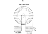
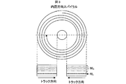
- the direction of the spiral of the guide track may be either a spiral in the outer circumferential direction as shown in FIG. 2 or a spiral in the inner circumferential direction as shown in FIG.
- FIG. 4 shows the layout of the optical disc 1.
- the optical disc 1 comprises at least one of the recording layers WL1 to WLn and the servo layer RL, and the servo layer RL is provided with the initial reproduction area 401.
- the initial reproduction area 401 is an area to be reproduced by servo light at the time of disc mounting in order to correct an optical axis deviation between the servo light and the recording / reproducing light.
- the procedure of the optical axis offset correction using the initial reproduction area 401 will be described later.
- the position of the initial reproduction area 401 is not limited to the inner circumference, the middle circumference, the outer circumference, etc. on the servo layer RL, and is arranged at any position on the servo layer RL.
- Reference numerals 414 to 4n4 denote data recording areas in which the user can record user data, and data recording areas are provided according to the number of recording layers WL of the optical disc. For example, as shown in FIG. The optical disk 1 is provided with 4n4 data recording areas.
- prewrite area 413 Before the user data is recorded in the data recording areas 414 to 4n4, data including address information is recorded in the prewrite area 413 (prewrite) in advance, and servo light Lr1 and recording / reproducing light Lb0 described later are recorded. It is used to correct the optical axis misalignment and is provided in any of the WL1 to WLn layers.
- pre-write area 413 is shown in the WL1 layer in FIG. 4, the arrangement of the pre-write area is not limited to this, and the pre-write area may be arranged in other layers. You may have.
- This pre-write area has the effect of being able to correct the optical axis deviation with the highest sensitivity when the disc is inclined at the time of optical axis deviation correction when in the WL1 layer, and when it is in all recording layers
- the pre-write area 413 is present at substantially the same position as the initial reproduction area 401 on the disc projection plane, and when a plurality of pre-write areas 413 exist, approximately at the same position on the disc projection plane where the plurality of pre-write areas 413 are present.
- a plurality of initial reproduction regions 401 exist in the servo layer RL. That is, as shown in FIG. 4, the initial adjustment area 401 exists in the depth direction of the pre-write area 413.
- the servo layer RL has disc-specific information for recording / reproduction on a wobbled guide track, and information for managing data to be recorded on the recording layer WL.
- An area for recording / reproducing information, etc. is provided, and the information and the area are not limited to the inner periphery, middle periphery, outer periphery, etc. on the servo layer RL, and are arranged at any position on the servo layer RL.
- the optical pickup 2 shown in FIG. 1 performs servo control on the servo layer RL, reproduces the address of the track and information unique to the disc from the wobbled guide track, and information for managing data to be recorded on the recording layer WL And an information optical system for recording and reproducing data on a plurality of recording layers WL having different distances from the servo layer RL.
- the servo laser 201 is, for example, a semiconductor laser that emits servo light having a wavelength of about 650 [nm], and emits servo light Lr1 of a predetermined light amount based on the control of the laser drive circuit 5 to enter the collimator lens 202.
- the collimator lens 202 converts the servo light Lr1 from divergent light into parallel light and makes the light enter the beam splitter 203.
- the beam splitter 203 has wavelength selectivity (dichroism) with different reflectance depending on the wavelength of the light beam, and reflects the light beam with a wavelength of about 650 [nm] at a rate of approximately 100% and has a wavelength of about 405
- the light beam of [nm] is transmitted at a rate of approximately 100%.
- the servo light Lr1 having a wavelength of about 650 [nm] is reflected at a rate of approximately 100% and is made incident on the next beam splitter 204.
- the servo light Lr1 transmitted through the beam splitter 204 is incident on the objective lens 205.
- the objective lens 205 condenses the servo light Lr1, passes through the recording layer WL of the optical disc 1, and focuses in the servo layer RL. At this time, the servo light Lr1 is reflected by the servo layer RL of the optical disc 1 and becomes a red reflected light beam Lr2 directed in the direction opposite to the servo light Lr1.
- the red reflected light beam Lr 2 is converted into parallel light by the objective lens 205, and is incident on the beam splitter 204. At this time, the red reflected light beam Lr 2 is reflected by the beam splitter 204 and is incident on the condenser lens 207.
- the condenser lens 207 converges the servo light Lr 2 and irradiates the photodetector 208 with the light.
- a signal for servo control such as a focus error signal and a tracking error signal, and a rotation for controlling rotation of the optical disc 1 from a wobbled guide track formed in the servo layer RL.
- a signal for reproduction is generated and output to the system controller 4.
- the system controller 4 outputs a focus control signal and a tracking control signal to the objective lens drive circuit 10 based on the focus error signal and the tracking error signal from the signal generation circuit 7. Further, the system controller 4 outputs a spindle control signal to the spindle drive circuit 11 based on the rotation synchronization signal output from the signal generation circuit 7.
- control is performed such that the disk 1 mounted on the spindle motor 3 has a predetermined rotational speed.
- the guide track formed in the servo layer RL of the optical disc 1 is formed in a spiral shape as shown in FIGS. 2 and 3, and tracking control is performed so that the servo light Lr1 follows the guide track of the servo layer.
- tracking control is performed so that the servo light Lr1 follows the guide track of the servo layer.
- the servo light Lr1 is irradiated to the servo layer RL of the optical disk 1, and the control of the system controller 4 is performed based on the light reception result of the red reflected light beam Lr2 which is the reflected light.
- focus control and tracking control of the objective lens 205 are performed to make the servo light Lr1 follow the guide track of the servo layer RL.
- the distance from the surface of the optical disc 1 on the side to which the servo light is incident to the servo layer RL is 0.6 mm in consideration of the influence of coma aberration due to the inclination of the optical disc 1 in recording and reproduction on the servo layer RL with servo light. It is desirable to have a degree.
- the recording / reproducing laser 209 is, for example, a semiconductor laser that emits the recording / reproducing light Lb0 having a wavelength of about 405 [nm], emits the recording / reproducing light Lb0 of a predetermined light amount based on the control of the laser drive circuit 6, and transmits it to the collimator lens 210. Let it strike.
- the collimator lens 210 converts the recording / reproducing light Lb 0 from divergent light into parallel light, reflects the light by the mirror 212, and then makes the light enter the beam splitter 213.
- the recording / reproducing light Lb 0 transmitted through the beam splitter 213 is incident on the relay lens 214.
- the relay lens 214 converts the recording / reproducing light Lb 0 from parallel light to convergent light or diverging light by the movable lens 214 A, and changes the convergence state of the recording / reproducing light Lb 0 by the fixed lens 214 B to enter the beam splitter 203.
- the movable lens 214A is configured to move integrally with the actuator 218, and drives the relay lens actuator 218 in the optical axis direction and the direction perpendicular to the optical axis according to the output of the relay lens drive circuit 9.
- the relay lens actuator 218 at the time of recording and reproduction is driven only in the optical axis direction, and only focus control for changing the convergence state of the recording and reproducing light Lb0 emitted from the fixed lens 214B is performed.
- the tracking control of Lb0 is performed by driving the objective lens actuator 206 and using the objective lens 205 together with the servo light Lr1. Servo control of servo light by the objective lens 205 will be described later.
- the beam splitter 203 transmits the recording / reproducing light Lb 0 according to its wavelength and makes it incident on the beam splitter 204.
- the beam splitter 204 transmits the recording / reproducing light Lb0 at a predetermined ratio and causes the light to enter the objective lens 205.
- the objective lens 205 condenses the recording / reproducing light Lb 0 and focuses it in the desired recording layer WL of the optical disc 1.
- the position of the blue light focus Fb1 of the recording / reproducing light Lb0 is determined by the convergence state at the time of being emitted from the fixed lens 214B of the relay lens 214.
- the blue light focus Fb1 at the time of recording and reproduction is moved in the focusing direction in the recording layer WL according to the position of the movable lens 214A.
- the blue light beam Lb1 is irradiated to the optical disc 1 to position the blue light focus Fb1 in the recording layer WL, and further, according to the position of the movable lens 214A in the relay lens 214, the depth from the servo layer RL of the focus Fb1 Is made to adjust the
- the moving distance of the movable lens 214A and the moving distance of the blue light focus Fb1 of the recording / reproducing light Lb0 are designed to be substantially proportional to each other. For example, when the movable lens 214A is moved by 1 mm, the recording / reproducing light Lb0 The blue light focal point Fb1 is moved by 30 [.mu.m].
- the blue beam Lb0r reflected by the recording layer WL successively enters the objective lens 205, the beam splitter 204, the beam splitter 203, and the relay lens 214, becomes parallel light, and enters the beam splitter 213.
- the blue reflected light beam Lb 0 r reflected by the beam splitter 213 is incident on the condenser lens 215.
- the condenser lens 215 converges the blue reflected light beam Lb 0 r and irradiates the photodetector 216 with the light.
- a signal for servo control such as a recording layer focus error signal and a mark tracking error signal, and a rotation for controlling the rotation of the optical disc 1 from the mark track recorded in the recording layer WL.
- a synchronization signal and a signal for reproducing a track address, and a signal for reproducing recorded user data are generated and output to the system controller 4.
- the system controller 4 outputs a focus control signal and a tracking control signal to the relay lens drive circuit 9 based on the recording layer focus error signal and the recording mark tracking error signal from the signal generation circuit 8.
- the objective lens 205 is configured to move integrally with the actuator 206, and the servo light Lr1 is generated by driving the actuator 206 in the focusing direction, the tracking direction, and the radial tilt direction according to the output of the objective lens drive circuit 10.
- Servo control is performed to follow the guide track in a state in which the servo layer RL is in focus.
- the system controller 4 drives the movable lens 214A only in the focusing direction based on the recording layer focus error signal and the mark tracking error signal, and drives the objective lens 205 in the focusing direction and tracking direction.
- Servo control is performed to position the blue light focus Fb1 on the recorded mark of the recording layer WL to be reproduced.
- the system controller 4 reproduces information from the change of the blue reflected beam Lb0r incident on the photodetector 216.
- the optical pickup 2 is moved to a desired position to reproduce the initial adjustment area 401 and the prewrite area 413 (1001), and the optical disc 1 starts rotation (1002). .
- the relay lens actuator 218 and the objective lens actuator 206 are initialized in order to reproduce the initial adjustment area 401 and the pre-write area 413 (1003).
- servo light Lr1 is irradiated from the servo laser 201, the objective lens actuator 206 is driven in the optical axis direction, and focus control is performed so that the servo light Lr1 is focused on the initial reproduction area 401 on the servo layer RL ( 1004)
- the focus control is performed until the FES (Focus Error Signal) reproduced by the servo light Lr1 becomes equal to or less than a predetermined reference value (1005).
- the objective lens actuator 206 is driven in a direction perpendicular to the optical axis, tracking control is performed on the guide track on the servo layer RL by the servo light Lr1 (1006), and TES (Tracking Error Signal) reproduced by servo light The tracking control is performed until the value of L falls below the reference value (1007).
- the address of the place where it was pulled in is reproduced, and the reproduced address is stored in a memory (not shown) in the system controller 4 via the signal generation circuit 7 (1008).
- the recording / reproducing light Lb0 is irradiated from the recording / reproducing laser 210, the relay lens actuator 218 is driven in the optical axis direction, and the focus control is performed so that the recording / reproducing light Lb0 is focused on the prewrite area 413 on the recording layer WL.
- the focus control is performed until the FES reproduced by the recording / reproducing light Lb0 becomes equal to or less than a predetermined reference value (1010).
- the relay lens actuator 218 is driven in a direction perpendicular to the optical axis, tracking control is performed on the pre-write area 413 on the recording layer WL by the recording / reproducing light Lb0 (1011), and TES reproduced by the recording / reproducing light Lb0 is Tracking control is performed until it becomes less than the reference value (1012).
- the data including the address information of the pulled-in portion is reproduced and the address is acquired (1013), and the reproduced address is stored in the memory (not shown) in the system controller 4 through the signal generation circuit 7 ( 1008).
- the address reproduced by the servo light stored at 1008 is compared with the address reproduced by the recording / reproducing light Lb0 stored at 1013 (1014). If they coincide, the relay lens actuator 218 newly mounts the optical disc 1 etc.
- the lens is fixed in the direction perpendicular to the optical axis and driven only in the optical axis direction unless it is necessary to correct the optical axis deviation, and the relay lens 214A performs only the focus control to track the servo light and the recording / reproducing light Lb0. Control is performed using only the objective lens 205.
- the objective lens actuator 206 is driven and controlled while the optical axes of the servo light and the recording / reproducing light Lb0 are aligned, and the focal positions of the servo light and the recording / reproducing light Lb0 are integrally displaced.
- the optical axes of the two laser beams can be tracking controlled without deviation.
- the address amount of the address reproduced by the recording / reproducing light Lb0 deviates from the address reproduced by the servo light
- the relay lens actuator 218 is driven in the direction perpendicular to the optical axis to correct the deviation of the optical axis of the recording / reproducing light Lb0 (1015), and returns to 1011 to execute the same processing as described above.
- the optical pickup 2 is moved to the recording / reproducing position (1016), and the recording / reproducing process is performed as described above. Execute (1017).
- the address is acquired from the servo light and then the address is acquired by the recording and reproducing light, but the flow of the process is not limited.
- the address may be acquired from the reproduction light, and then the address may be acquired by the servo light.
- the prewrite area 413 is recorded by the recording / reproducing light Lb 0. And information obtained by reproducing the guide track included on the servo layer RL by the servo light Lr1, and information reproduced by the servo light and the recording and reproducing light Lb0.
- the initial adjustment area 401 and the prewrite area 413 shown in FIG. 4 are only for one address, and along with the area of the initial adjustment area 401 and the prewrite area 413, the servo light Lr1 and the recording
- the prewrite area 413 is on the same disk surface of the previous layer of the initial adjustment area 401 as in the first embodiment. Will be placed. Therefore, as for the optical axis misalignment correction of the servo light Lr1 and the recording and reproducing light Lb0 of the optical disk recording and reproducing apparatus shown in FIG.
- the servo light described in Example 1 is performed by performing focus control and tracking control until the recording and reproduction light Lb0 performs focus control and tracking control in the recording layer WL until FES and TES become less than a predetermined reference value.
- the servo layer RL and the recording layer WL are separately formed, and a prewrite area 413 for one address is provided at any position of at least any layer of the recording layer WL, and the same disk as the prewrite area 413.
- the optical disc 1 having an initial adjustment area 401 for one address on the servo layer RL on the surface, information obtained by reproducing the pre-write area 413 with the recording / reproducing light Lb0 and the initial adjustment area 401 with the servo light Lr1.
- focus control and tracking control on the basis of information obtained by reproduction, it becomes possible to correct the deviation of the optical axis between the recording / reproducing light Lb0 and the servo light Lr1, and after executing the correction, recording / reproducing is performed.
- the desired recording layer WL can be reliably tracked on the guide track on the servo layer RL.
- FIG. 10 shows an optical disc recording and reproducing apparatus according to a third embodiment of the present invention.
- the optical disc recording and reproducing apparatus according to the third embodiment of the present invention differs from the optical disc recording and reproducing apparatus according to the first or second embodiment in that the actuator 219 drives the collimator lens 210 in the optical pickup 14 perpendicular to the optical axis.
- the point at which the collimator lens drive circuit 12 is provided, and the point at which the actuator 218 attached to the relay lens is driven only in the optical axis direction. That is, in the third embodiment of the present invention, in the optical disc described in the first or second embodiment, the focus control of the recording / reproducing light Lb0 at 1009 of FIG. 6 or 9 is performed using the relay lens 214A.
- Tracking control of 1011 is performed using a collimator lens 210. Therefore, the system controller 4 outputs a focus control signal to the relay lens drive circuit 9 and a tracking control signal to the collimator lens drive circuit 12 based on the recording layer focus error signal and the recording mark tracking error signal from the signal generation circuit 8.
- the relay lens drive circuit 9 drives the actuator 218 in the optical axis direction based on the focus control signal to perform focus control, and the collimator lens drive circuit 12 moves the actuator 219 vertically to the optical axis based on the tracking control signal. Drive to perform tracking control.
- the focus control of the recording / reproducing light Lb0 is performed using the relay lens 214A based on the information obtained by reproducing the pre-write area 413 with the recording / reproducing light Lb0.
- Tracking control is performed using the collimator lens 210, and focusing control and tracking control of the servo light Lr1 are performed using the objective lens 205 based on information obtained by reproducing the initial adjustment area 401 with the servo light Lr1.
- FIG. 11 shows an optical disc recording and reproducing apparatus according to a fourth embodiment of the present invention.
- the optical disk recording and reproducing apparatus according to the fourth embodiment of the present invention differs from the optical disk recording and reproducing apparatus according to the first to third embodiments in that the optical pickup 15 is provided with an actuator 220 for rotating the mirror 212 and a mirror driving circuit 13. The point is that the actuator 218 attached to the relay lens is driven only in the optical axis direction. That is, in the fourth embodiment of the present invention, in the optical disk according to the first or second embodiment, the focus control of the recording / reproducing light Lb0 at 1009 of FIG. 6 or 9 is performed using the relay lens 214A. Tracking control of 1011 is performed using a mirror 212.
- the system controller 4 outputs a focus control signal to the relay lens drive circuit 9 and a tracking control signal to the mirror drive circuit 13 based on the recording layer focus error signal and the recording mark tracking error signal from the signal generation circuit 8,
- the lens drive circuit 9 drives the actuator 218 in the optical axis direction based on the focus control signal to perform focus control, and the mirror drive circuit 13 rotationally drives the actuator 220 based on the tracking control signal to form a relay lens.
- the tracking control is performed by adjusting the recording / reproducing light Lb0 to be incident.
- the focus control of the recording / reproducing light Lb0 is performed using the relay lens 214A based on the information obtained by reproducing the pre-write area 413 with the recording / reproducing light Lb0.
- Tracking control is performed using the collimator lens 210, and focusing control and tracking control of the servo light Lr1 are performed using the objective lens 205 based on information obtained by reproducing the initial adjustment area 401 with the servo light Lr1.
- FIG. 12 shows a flow of recording and reproduction processing of the optical disk recording and reproduction apparatus according to the fifth embodiment of the present invention.
- optical disc 1 according to the fifth embodiment of the present invention The difference between the optical disc 1 according to the fifth embodiment of the present invention and the first to fourth embodiments is that the prewrite to the prewrite area 413 shown in FIG. 4 is performed before the user records in the data recording areas 414 to 4n4. That is, each optical disc recording and reproducing apparatus performs on an unrecorded optical disc. Therefore, as shown in FIG. 12, processes 1018 to 1020 are added to the recording and reproducing process flows of the first to fourth embodiments.
- the process shown in FIG. 5 is executed at the time of recording and reproduction, and the focus control of the recording and reproduction light shown in FIG. 12 is executed until the FES becomes less than a predetermined value (1009, 1010) .
- the initial adjustment area is reproduced using the recording / reproducing light, and it is checked whether or not pre-writing is performed in the initial reproduction area, and it is judged as an unrecorded disc if pre-writing is not performed. Then, if pre-write is performed, the process proceeds to step 1011.
- the pre-write area track control by the recording / reproducing light is executed.
- the relay lens 214A or the collimator lens 210 or the mirror 212 is set to a predetermined initial position.
- the value to be set is such that at least the focus of the recording / reproducing light is in focus in the pre-write area 413.
- data including address information is recorded in the prewrite area (1020), and track control of recording / reproducing light is executed using the data including the prewritten address information (1011).
- the processes after the track control by the recording / reproducing light are the same as in the first to fourth embodiments.
- the optical disk device which performs the recording for the first time performs the pre-write on the unrecorded optical disk, and the optical disk to be additionally recorded or reproduced later has the optical axis deviation
Landscapes
- Optical Recording Or Reproduction (AREA)
Abstract
記録再生光及びサーボ光の波長が互いに異なる場合、または記録層をBlu-ray Disc(登録商標)相当の密度とし、対物レンズのワーキングディスタンスが光ディスク表面からサーボ層までの距離に満たない場合、あるいはその両方の場合に、サーボ層上のガイドトラック上に所望の記録層でのトラックキングを確実に行うことのできる多層光ディスク記録再生装置と多層光ディスクを提供することを課題としている。 かかる課題を解決するため、本発明においては記録層上にプリライト領域を設けて、該プリライト領域を記録再生光で再生して得られる情報と、サーボ層上のガイドトラックをサーボ光で再生して得られる情報を比較し、該比較において記録再生光の光軸を補正することで記録再生光とサーボ光の光軸ずれを補正することが出来る。
Description
本発明は、サーボ層と記録層が分離形成された光ディスク及び
それに情報の記録及び/又は再生を行う光ディスク記録再生装置及び記録再生手法に関する。
それに情報の記録及び/又は再生を行う光ディスク記録再生装置及び記録再生手法に関する。
サーボ層及び記録層が分離形成された多層光ディスクが開発されている。
これは、サーボ層でサーボ制御に用いるサーボ用光ビーム(以下、サーボ光と表記)と、記録層で記録及び/又は再生(以下、記録再生と表記)を行う記録再生用光ビーム(以下、記録再生光と表記)の2種類の光ビームを使用し、サーボ層及び記録層それぞれに焦点を合わせ、半径方向の制御をサーボ層に埋め込まれた信号を元に制御を行い、情報の記録を行うものである。(特許文献1)
しかしながら、同一光軸のサーボ光と記録再生光を用いて、ガイドトラックを有するサーボ層と、該サーボ層の奥層又は手前層或いはその両方に複数の記録層を設けた光ディスクの所望記録層の所望トラックに記録再生光を移動させる場合、2つの光軸がずれてしまうため、図7に示す通り光軸ずれ103の量が異なる多層光ディスク記録再生装置では、サーボ光でトラッキングを行っても記録再生光が所望の記録再生位置に収束するとは限らず、所望の記録再生位置にアクセスできず記録再生ができなくなるといった課題がある。
前記課題を解決するために特許文献1には「基板上に少なくともガイドトラックを有するサーボ層と情報を記録再生する複数の記録層を有する多層光ディスクに対して、(中略) 、前記光軸ずれ検出手段は、前記サーボ用トラッキングエラー信号と前記記録再生用トラッキングエラー信号とに基づき前記光軸ずれ量を検出し、前記補正手段は、前記サーボ用トラッキングエラー信号に基づき所望のガイドトラックにトラッキングした後、前記サーボ用トラッキングエラー信号を前記光軸ずれ量だけ補正し前記記録再生用光ビームを所望の前記ガイドトラック上に照射させるように構成することができる。」とある。しかしながら、特許文献1記載の手法では以下に示す二つの課題がある。
一つ目の課題は、記録再生光及びサーボ光は共にサーボ層上のガイドトラックに照射されるため、記録再生光及びサーボ光の波長が互いに異なる場合に、記録再生光及びサーボ光の各々の波長でトラッキング可能な構造がサーボ層に必要になるという課題である。
2つ目の課題は現行のBlu-ray Disc(登録商標)相当の密度で記録を行う場合、図7に示す通り、現在主に用いられている光ピックアップの構成では対物レンズ205のワーキングディスタンス102が光ディスク表面からサーボ層までの距離101より小さいことが想定されるため、記録再生用光ビームをサーボ層に照射できないという課題である。
本発明は前記2つの課題に鑑みてなされたものであり、記録再生光及びサーボ光の波長が互いに異なる場合、または記録層をBlu-ray Disc(登録商標)相当の密度とし、対物レンズのワーキングディスタンスが光ディスク表面からサーボ層までの距離に満たない場合、あるいはその両方の場合に、サーボ層上のガイドトラック上に所望の記録層でのトラッキングをより正確に行うことのできる多層光ディスクと該光ディスクを記録再生する装置を提供することを目的としている。
上記課題は記録層にサーボ層と同期をとるためのプリライト領域を設けることで解決できる。
サーボ層及び記録層が分離形成された光ディスクの記録再生装置において、記録再生光及びサーボ光の波長が互いに異なる場合、または記録層をBlu-ray Disc(登録商標)相当の密度とし、対物レンズのワーキングディスタンスが光ディスク表面からサーボ層までの距離に満たない場合、あるいはその両方の課題がある場合に、記録再生光とサーボ光の光軸ずれを補正し、サーボ層上のガイドトラックに所望の記録層でのトラッキングをより正確に行うことが出来る。
まず、本願において開示される発明の代表的な実施の形態について概要を説明する。
本発明の代表的な実施例は、少なくともガイドトラックを有するサーボ層と情報を記録再生する複数の記録層を有し、該記録層に少なくともプリライト領域を有する多層光ディスクと、該多層光ディスクを記録再生する光ディスク記録再生装置であって、前記サーボ層で用いるサーボ光と前記記録層で用いる記録再生光の光軸ずれを、サーボ光でサーボ層のガイドトラックを再生して得られる情報と記録再生光で記録層のプリライト領域を再生して得られる情報を元に補正することを特徴とする光ディスク記録再生装置である。
次に実施の形態について更に詳述する。尚、発明を実施するための最良の形態を説明するための全図において、前記の図と同一の機能を有する部品には同一の符号を付して、その繰り返しの説明は省略する。
以下、本発明を実施するための形態について図を用いて説明する。
図1は本実施例による光ディスク記録再生装置の構成を示すブロック図である。
図1に示す光ディスク1は、図2及び図3に示すように記録再生を行うトラックのアドレス及び記録再生のためのディスク固有の情報がウォブルされた案内溝としてガイドトラックが形成されたサーボ層RLと、ユーザデータが記録再生可能な複数の記録層WLを有している。サーボ層RLのガイドトラックは、スパイラル状に形成されている。
前記ガイドトラックのスパイラルの方向は、図2に示すように外周方向のスパイラルでも、図3に示すように内周方向のスパイラルでもどちらでも良い。また、図4は光ディスク1のレイアウトを示す。
光ディスク1は前記記載の通り、少なくとも一つの記録層WL1乃至WLnとサーボ層RLから成り、サーボ層RLには初期再生領域401が具備される。
401の初期再生領域はサーボ光と記録再生光の光軸ずれを補正するために、ディスクマウント時にサーボ光で再生する領域である。初期再生領域401を用いた光軸ずれ補正の手順は後述する。初期再生領域401の位置はサーボ層RL上の内周、中周、外周など限定されず、サーボ層RL上のいずれかの位置に配置される。
414乃至4n4はユーザがユーザデータを記録可能なデータ記録領域であり、光ディスクの記録層WLの数に応じてデータ記録領域は具備され、例えば図4に示す通り、n層の記録層WLを持つ光ディスク1に対しては、4n4のデータ記録領域が具備される。
413のプリライト領域にはデータ記録領域414乃至4n4にユーザデータが記録されるよりも以前に予め、アドレス情報を含むデータが記録されており(プリライト)、後述するサーボ光Lr1と記録再生光Lb0の光軸ずれを補正するために利用され、WL1層乃至WLn層のいずれかの層に具備される。図4において、プリライト領域413はWL1層に示されているが、プリライト領域の配置はこれに限らず、他の層に配置しても良く、また複数の記録層WLが複数個所でプリライト領域を有しても良い。なお、このプリライト領域は、WL1層にある場合は光軸ずれ補正時のディスクに傾きがある場合に最も感度良く光軸ずれを補正できるという効果があり、全ての記録層にある場合は層ごとにディスク面のずれが存在する場合に、より正確に光軸ずれを補正することができるという効果がある。また、複数の記録層のうち奥の層にある場合には、ディスクの製造が簡易になるという効果がある。
但し、プリライト領域413は初期再生領域401とディスク投影面上で略同じ位置に存在し、プリライト領域413が複数存在するときは、複数のプリライト領域413が存在するディスク投影面上で略同じ位置のサーボ層RLに初期再生領域401は複数存在する。つまり図4に示す通り、プリライト領域413の奥層方向には初期調整領域401が存在する。
また図4には図示していないが、サーボ層RLは記録再生のためのディスク固有の情報をウォブルされたガイドトラックに有しており、また記録層WLに記録するデータを管理するための情報等を記録・再生するための領域が具備され、該情報と領域はサーボ層RL上の内周、中周、外周など限定されず、サーボ層RL上のいずれかの位置に配置される。
図1に示す光ピックアップ2はサーボ層RLにサーボ制御を行うとともに、ウォブルされたガイドトラックからトラックのアドレス及びディスク固有の情報を再生し、記録層WLに記録するデータを管理するための情報等を記録・再生するためのサーボ光学系と、サーボ層RLからの距離が異なる複数の記録層WLにデータを記録・再生するための情報光学系で構成されている。
まず、記録動作について説明を行う。
始めに光ピックアップ2のサーボ光学系について説明する。サーボ用のレーザ201は例えば波長約650[nm]のサーボ光を出射する半導体レーザであり、レーザ駆動回路5の制御に基づいて所定光量のサーボ光Lr1を出射し、コリメータレンズ202へ入射させる。コリメータレンズ202は、サーボ光Lr1を発散光から平行光に変換し、ビームスプリッタ203へ入射させる。ビームスプリッタ203は、光ビームの波長により反射率が異なる波長選択性(ダイクロイック性)を有しており、波長約650[nm]の光ビームをほぼ100%の割合で反射すると共に、波長約405[nm]の光ビームをほぼ100%の割合で透過させるようにしている。これにより波長約650[nm]のサーボ光Lr1をほぼ100%の割合で反射し、次のビームスプリッタ204へ入射させる。ビームスプリッタ204を透過したサーボ光Lr1は対物レンズ205へ入射される。対物レンズ205は、サーボ光Lr1を集光し、光ディスク1の記録層WLを透過してサーボ層RL内に合焦する。このときサーボ光Lr1は、光ディスク1のサーボ層RLにおいて反射され、サーボ光Lr1と反対方向へ向かう赤色反射光ビームLr2となる。
赤色反射光ビームLr2は対物レンズ205により平行光に変換され、ビームスプリッタ204へ入射される。このとき赤色反射光ビームLr2は、ビームスプリッタ204により反射され、集光レンズ207へ入射される。集光レンズ207はサーボ光Lr2を収束させ、フォトディテクタ208へ照射する。信号生成回路7ではフォトディテクタ208の出力からフォーカス誤差信号及びトラッキング誤差信号等のサーボ制御のための信号と、サーボ層RLに形成されたウォブルされたガイドトラックから光ディスク1の回転を制御するための回転同期信号及びガイドトラックのアドレスを再生する信号と、記録層WLに記録を行うための光ビームの強度等のディスク固有の情報、或いは記録層WLに記録したユーザデータを管理するための情報等を再生するための信号を生成し、システムコントローラ4に出力する。システムコントローラ4では信号生成回路7からのフォーカス誤差信号及びトラッキング誤差信号に基づいてフォーカス制御信号及びトラッキング制御信号を対物レンズ駆動回路10に出力する。また、システムコントローラ4では信号生成回路7から出力される回転同期信号に基づいてスピンドル制御信号をスピンドル駆動回路11に出力する。スピンドル駆動回路11の出力によりスピンドルモータ3を駆動することにより、スピンドルモータ3に装着されたディスク1が所定の回転速度となるように制御が行われる。
また、光ディスク1のサーボ層RLに形成されたガイドトラックは図2、3に示すようにスパイラル状に形成されており、サーボ光Lr1がサーボ層のガイドトラックを追従するようにトラッキング制御を行うことによりディスク1の内周から外周、もしくは外周から内周まで連続して記録或いは再生を行うことが可能となっている。
以上のように、光ピックアップ2のサーボ光学系では、サーボ光Lr1を光ディスク1のサーボ層RLに照射し、その反射光である赤色反射光ビームLr2の受光結果を基に、システムコントローラ4の制御に基づいて対物レンズ205のフォーカス制御及びトラッキング制御を行い、サーボ光Lr1をサーボ層RLのガイドトラックに追従させるようにしている。なお、サーボ光でのサーボ層RLへの記録再生における光ディスク1の傾きによるコマ収差の影響を考慮して、サーボ光が入射する側の光ディスク1の表面からサーボ層RLまでの距離は0.6mm程度とするのが望ましい。
次いで光ピックアップ2の情報光学系について説明する。記録再生用レーザ209は例えば波長約405[nm]の記録再生光Lb0を出射する半導体レーザであり、レーザ駆動回路6の制御に基づいて所定光量の記録再生光Lb0を出射し、コリメータレンズ210へ入射させる。コリメータレンズ210は、記録再生光Lb0を発散光から平行光に変換し、ミラー212にて反射された後ビームスプリッタ213へ入射させる。ビームスプリッタ213を透過した記録再生光Lb0はリレーレンズ214へ入射される。リレーレンズ214は、可動レンズ214Aにより記録再生光Lb0を平行光から収束光又は発散光に変換し、さらに固定レンズ214Bにより当該記録再生光Lb0の収束状態を変化させて、ビームスプリッタ203へ入射させる。ここで可動レンズ214Aはアクチュエータ218と一体で動くように構成されており、リレーレンズ駆動回路9の出力に応じて、リレーレンズアクチュエータ218を光軸方向と光軸に対して垂直方向に駆動することが可能となっており、固定レンズ214Bから出射される記録再生光Lb0の収束状態を変化させると共に、サーボ光Lr1と記録再生光Lb0の光軸ずれを補正することが可能である。しかし、記録再生時のリレーレンズアクチュエータ218は光軸方向のみに駆動され、固定レンズ214Bから出射される記録再生光Lb0の収束状態を変化させるフォーカス制御のみを行うものとし、記録再生時の記録光Lb0のトラッキング制御については、対物レンズアクチュエータ206を駆動し、サーボ光Lr1と共に対物レンズ205を用いて実行される。対物レンズ205によるサーボ光のサーボ制御は後述する。
ビームスプリッタ203は、記録再生光Lb0をその波長に応じて透過し、ビームスプリッタ204へ入射させる。ビームスプリッタ204は、記録再生光Lb0を所定の割合で透過し、対物レンズ205へ入射させる。対物レンズ205は、記録再生光Lb0を集光し、光ディスク1の所望の記録層WL内に合焦する。ここで記録再生光Lb0の青色光焦点Fb1の位置は、リレーレンズ214の固定レンズ214Bから出射される際の収束状態により定められることになる。
すなわち記録再生時の青色光焦点Fb1は、可動レンズ214Aの位置に応じて記録層WL内をフォーカス方向に移動することになる。これにより、光ディスク1に青色光ビームLb1を照射して青色光焦点Fb1を記録層WL内に位置させ、さらにリレーレンズ214における可動レンズ214Aの位置に応じて当該焦点Fb1のサーボ層RLからの深さを調整するようになされている。
可動レンズ214Aの移動距離と記録再生光Lb0の青色光焦点Fb1の移動距離とがほぼ比例関係となるように設計されており、例えば可動レンズ214Aを1[mm]移動させると、記録再生光Lb0の青色光焦点Fb1が30[μm]移動するようにしている。
記録層WLで反射された青色ビームLb0rは、対物レンズ205、ビームスプリッタ204、ビームスプリッタ203、リレーレンズ214に続けて入射し、平行光となり、ビームスプリッタ213に入射する。ビームスプリッタ213で反射された青色反射光ビームLb0rは集光レンズ215に入射される。集光レンズ215は青色反射光ビームLb0rを収束させ、フォトディテクタ216へ照射する。信号生成回路8ではフォトディテクタ216の出力から記録層フォーカス誤差信号及びマークトラッキング誤差信号等のサーボ制御のための信号と、記録層WLに記録されたマークトラックから光ディスク1の回転を制御するための回転同期信号及びトラックのアドレスを再生する信号や、記録されたユーザデータを再生するための信号を生成し、システムコントローラ4に出力する。システムコントローラ4では信号生成回路8からの記録層フォーカス誤差信号及び記録マークトラッキング誤差信号に基づいてフォーカス制御信号及びトラッキング制御信号をリレーレンズ駆動回路9に出力する。
また、対物レンズ205はアクチュエータ206と一体で動くように構成されており、対物レンズ駆動回路10の出力に応じてアクチュエータ206をフォーカス方向及びトラッキング方向及びラジアルチルト方向に駆動することによりサーボ光Lr1がサーボ層RLに合焦した状態でガイドトラックを追従するようにサーボ制御を行う。
その後、記録再生用レーザ209の出力を記録用の出力に変化をさせることによって、記録層WLにマークを形成し、情報の記録を行うことが出来る。これにより、記録層WLには記録されたマーク列からなるマークトラックが形成される。
次に再生動作について説明を行う。
再生時には、システムコントローラ4は前記記録層フォーカス誤差信号及び、前記マークトラッキング誤差信号を元に前記可動レンズ214Aをフォーカス方向のみに駆動し、対物レンズ205をフォーカス方向及び、トラッキング方向に駆動することで、青色光焦点Fb1を再生したい記録層WLの記録されたマーク上に位置付けるようにサーボ制御を行う。
そして、システムコントローラ4は、フォトディテクタ216に入射する青色反射ビームLb0rの変化から、情報の再生を行う。
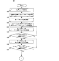
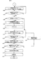
次に、本発明の光ディスク記録再生装置の記録再生光とサーボ光の光軸ずれ補正の手順について図5のフローチャートを用いて説明する。
まず、光ディスク1の挿入(1000)を確認すると、初期調整領域401とプリライト領域413を再生するために光ピックアップ2は所望の位置に移動し(1001)、光ディスク1は回転を開始する(1002)。次に、初期調整領域401とプリライト領域413を再生するためにリレーレンズアクチュエータ218及び対物レンズアクチュエータ206の初期設定を行う(1003)。
その後、サーボ用レーザ201からサーボ光Lr1を照射し、対物レンズアクチュエータ206を光軸方向に駆動してサーボ層RL上の初期再生領域401にサーボ光Lr1が合焦するようフォーカス制御を実行し (1004)、サーボ光Lr1によって再生されるFES(Focus Error Signal)が予め定めた基準値以下になるまでフォーカス制御を行う(1005)。次に、対物レンズアクチュエータ206を光軸に垂直方向に駆動して、サーボ光Lr1によるサーボ層RL上のガイドトラックにトラッキング制御を行い(1006)、サーボ光で再生されるTES(Tracking Error Signal)が基準値以下になるまで、トラッキング制御を行う(1007)。次に引き込んだ箇所のアドレスを再生し、再生したアドレスは信号生成回路7を介してシステムコントローラ4内のメモリ(図示せず)に保存する(1008)。
その後、記録再生用レーザ210から記録再生光Lb0を照射し、リレーレンズアクチュエータ218を光軸方向に駆動して記録層WL上のプリライト領域413に記録再生光Lb0が合焦するようフォーカス制御を実行し (1009)、記録再生光Lb0によって再生されるFESが予め定めた基準値以下になるまでフォーカス制御を行う(1010)。次に、リレーレンズアクチュエータ218を光軸に垂直方向に駆動して、記録再生光Lb0による記録層WL上のプリライト領域413にトラッキング制御を行い(1011)、記録再生光Lb0で再生されるTESが基準値以下になるまで、トラッキング制御を行う(1012)。次に引き込んだ箇所のアドレス情報を含むデータをい再生し 、アドレスを取得し(1013)、再生したアドレスは信号生成回路7を介してシステムコントローラ4内のメモリ(図示せず)に保存する(1008)。
その後、1008で保存したサーボ光で再生したアドレスと1013で保存した記録再生光Lb0で再生したアドレスを比較し(1014)、一致していればリレーレンズアクチュエータ218は新たに光ディスク1をマウントするなどの要因で光軸ずれ補正を必要としない限り、光軸に垂直方向には固定し、光軸方向のみに駆動させ、リレーレンズ214Aではフォーカス制御のみを行い、サーボ光と記録再生光Lb0のトラッキング制御は対物レンズ205のみを用いて行う。該サーボ光と記録再生光Lb0の光軸が合った状態でトラッキング制御については対物レンズアクチュエータ206のみを駆動し制御を行うことで、サーボ光と記録再生光Lb0の焦点位置は一体となって変位するため2つのレーザ光の光軸は、ずれることなくトラッキング制御可能となる。
1014の判断において記録再生光Lb0で再生されるアドレスとサーボ光で再生されるアドレスが一致していなければ、記録再生光Lb0で再生されるアドレスがサーボ光で再生されるアドレスからずれたアドレス量だけリレーレンズアクチュエータ218を光軸に垂直方向に駆動し、記録再生光Lb0の光軸ずれを補正し(1015)、1011に戻り前記同様の処理を実行する。
1014の判断において記録再生光Lb0で再生されるアドレスとサーボ光で再生されるアドレスが一致していれば、記録再生位置に光ピックアップ2を移動し(1016)、前記記載の通り記録再生処理を実行する(1017)。
ここで前記記載の通り、プリライト領域413へのプリライトを各光ディスク記録再生装置が行う場合は、1011の処理で未記録の光ディスク1に対してのみプリライトを行う。該各光ディスク記録再生装置でプリライトされた光ディスク1に対して再生或いは追記する際には、該プリライトに従い、図5と図6に示すサーボ光と記録再生光Lb0の光軸ずれ補正を実行する。
図5、図6に示す光軸ずれ補正処理の流れでは、サーボ光からアドレスの取得を行い、次いで記録再生光よるアドレスの取得を行っているが、その処理の流れは限定されず、例えば記録再生光からアドレスの取得を行い、次いでサーボ光によるアドレス取得を行っても良い。
以上のようにサーボ層RL及び記録層WLが分離形成され、少なくとも記録層WLのいずれかの層のいずれかの位置にプリライト領域413を具備した光ディスク1において、記録再生光Lb0で該プリライト領域413を再生して得られる情報と、サーボ光Lr1でサーボ層RL上に有されるガイドトラックを再生して得られる情報と、また前記サーボ光で再生される情報と記録再生光Lb0で再生される情報を比較した結果から記録再生光Lb0とサーボ光Lr1との光軸ずれを補正した後に、記録再生を実行することで、サーボ層RL上のガイドトラックに所望の記録層WLでのトラッキングを確実に行うことが出来る。
本発明の実施例2による光ディスク1では、図4に示す初期調整領域401とプリライト領域413は1アドレス分のみとされ、該初期調整領域401とプリライト領域413の領域に伴い、サーボ光Lr1と記録再生光Lb0の光軸ずれ補正の手順は図8乃至9に示される通りとなる。本発明の実施例2によるサーボ光Lr1と記録再生光Lb0の光軸ずれ補正の手順図8乃至図9が、本発明の実施例1による光軸ずれ補正の手順図5乃至6と相違する点は、サーボ光Lr1と記録再生光Lb0によるアドレス再生(1008と1013)を省略し、該処理に伴いサーボ光Lr1と記録再生光Lb0により再生されるアドレス比較の判断を省略し(1014)、該処理に伴い記録再生光Lb0の光軸ずれ補正1015を省略した点である。
本発明の実施例2で用いる初期調整領域401とプリライト領域413が1アドレス分のみ具備される前記光ディスク1は実施例1と同様にプリライト領域413は初期調整領域401の手前層の同じディスク面上に配置される。そのため、実施例1と同様の図1に示す光ディスク記録再生装置のサーボ光Lr1と記録再生光Lb0の光軸ずれ補正は、サーボ光Lr1はサーボ層RLでFESとTESが予め定めた基準値以下になるまでフォーカス制御とトラッキング制御を行い、記録再生光Lb0は記録層WLでFESとTESが予め定めた基準値以下になるまでフォーカス制御とトラッキング制御を行うことで、実施例1記載のサーボ光Lr1によるアドレス再生と記録再生光Lb0によるアドレス再生と前記サーボ光Lr1と記録再生光Lb0で再生される2つのアドレスの比較を行うことなく、サーボ光Lr1と記録再生光Lb0の光軸ずれを補正することが出来る。
以上のようにサーボ層RL及び記録層WLが分離形成され、少なくとも記録層WLのいずれかの層のいずれかの位置に1アドレス分のプリライト領域413を具備し、また該プリライト領域413と同じディスク面上のサーボ層RL上に1アドレス分の初期調整領域401を具備した光ディスク1において、記録再生光Lb0で該プリライト領域413を再生して得られる情報と、サーボ光Lr1で初期調整領域401を再生して得られる情報を元に、各々フォーカス制御とトラッキング制御を行うことで、記録再生光Lb0とサーボ光Lr1との光軸ずれ補正が可能となり、該補正を実行した後に記録再生を実行することで、サーボ層RL上のガイドトラックに所望の記録層WLでのトラッキングを確実に行うことが出来る。
図10に本発明の実施例3による光ディスク記録再生装置を示す。本発明の実施例3による光ディスク記録再生装置が、実施例1または実施例2による光ディスク記録再生装置と相違する点は、光ピックアップ14にコリメータレンズ210を光軸に垂直方向に駆動するアクチュエータ219とコリメータレンズ駆動回路12が具備された点と、リレーレンズに付随するアクチュエータ218が光軸方向のみに駆動される点である。つまり、本発明の実施例3では実施例1または2に記載の光ディスクにおいて、図6または図9の1009の記録再生光Lb0のフォーカス制御はリレーレンズ214Aを用いて行い、図6または図9の1011のトラッキング制御はコリメータレンズ210を用いて行う。そのため、システムコントローラ4では信号生成回路8からの記録層フォーカス誤差信号及び記録マークトラッキング誤差信号に基づいてフォーカス制御信号をリレーレンズ駆動回路9に、トラッキング制御信号をコリメータレンズ駆動回路12に出力し、リレーレンズ駆動回路9は前記フォーカス制御信号に基づいてアクチュエータ218を光軸方向に駆動し、フォーカス制御を行い、コリメータレンズ駆動回路12は前記トラッキング制御信号に基づいてアクチュエータ219を光軸に垂直方向に駆動してトラッキング制御を行う。
以上のように実施例1乃至2に記載の光ディスク1において、記録再生光Lb0で該プリライト領域413を再生して得られる情報を元に、記録再生光Lb0のフォーカス制御は前記リレーレンズ214Aを用いて、トラッキング制御は前記コリメータレンズ210を用いて行い、サーボ光Lr1で初期調整領域401を再生して得られる情報を元に、サーボ光Lr1のフォーカス制御とトラッキング制御を対物レンズ205を用いて行い、前記サーボ光Lr1と記録再生光Lb0の光軸ずれを補正した後に、記録再生を実行することで、サーボ層RL上のガイドトラックに所望の記録層WLでのトラッキングを確実に行うことが出来る。
図11に本発明の実施例4による光ディスク記録再生装置を示す。本発明の実施例4による光ディスク記録再生装置が、実施例1乃至3による光ディスク記録再生装置と相違する点は、光ピックアップ15にミラー212を回転駆動するアクチュエータ220とミラー駆動回路13が具備された点と、リレーレンズに付随するアクチュエータ218が光軸方向のみに駆動される点である。つまり、本発明の実施例4では実施例1または2に記載の光ディスクにおいて、図6または図9の1009の記録再生光Lb0のフォーカス制御はリレーレンズ214Aを用いて行い、図6または図9の1011のトラッキング制御はミラー212を用いて行う。そのため、システムコントローラ4では信号生成回路8からの記録層フォーカス誤差信号及び記録マークトラッキング誤差信号に基づいてフォーカス制御信号をリレーレンズ駆動回路9に、トラッキング制御信号をミラー駆動回路13に出力し、リレーレンズ駆動回路9は前記フォーカス制御信号に基づいてアクチュエータ218を光軸方向に駆動し、フォーカス制御を行い、ミラー駆動回路13は前記トラッキング制御信号に基づいてアクチュエータ220を回転駆動して、リレーレンズに入光する記録再生光Lb0を調整してトラッキング制御を行う。
以上のように実施例1乃至2に記載の光ディスク1において、記録再生光Lb0で該プリライト領域413を再生して得られる情報を元に、記録再生光Lb0のフォーカス制御は前記リレーレンズ214Aを用いて、トラッキング制御は前記コリメータレンズ210を用いて行い、サーボ光Lr1で初期調整領域401を再生して得られる情報を元に、サーボ光Lr1のフォーカス制御とトラッキング制御を対物レンズ205を用いて行い、前記サーボ光Lr1と記録再生光Lb0の光軸ずれを補正し記録再生を実行することで、サーボ層RL上のガイドトラックに所望の記録層WLでのトラッキングを確実に行うことが出来る。
図12に本発明の実施例5による光ディスク記録再生装置の記録再生処理フローを示す。
本発明の実施例5による光ディスク1が実施例1乃至実施例4と相違する点は、図4に示すプリライト領域413へのプリライトは、ユーザがデータ記録領域414乃至4n4に記録するよりも以前に、つまり未記録の光ディスクに対して、各光ディスク記録再生装置が行う点である。そのため図12に示す通り、実施例1乃至実施例4の記録再生処理フローに対して、処理1018乃至1020が追加されている。
実施例1乃至実施例4同様に記録再生時には図5に示す処理を実行し、図12に示される記録再生光のフォーカス制御をFESが予め定めた値以下になるまで実行する (1009、1010)。その後記録再生光を用いて初期調整領域の再生を行い、初期再生領域にプリライトが行われているか否かを検査し、プリライトが行われていなければ未記録ディスクであると判断し1019の処理に移り、プリライトが行われていれば1011の処理に移り、実施例1乃至4同様に記録再生光によるプリライト領域トラック制御を実行する。
未記録のディスクに対しては、リレーレンズ214Aもしくはコリメータレンズ210もしくはミラー212を予め定めた初期位置に設定する。このとき、設定される値は少なくとも記録再生光の焦点がプリライト領域413内に合焦されるものである。その後、プリライト領域にアドレス情報を含むデータの記録を行い(1020)、プリライトしたアドレス情報を含むデータを用いて、記録再生光のトラック制御を実行する(1011)。記録再生光によるトラック制御以降の処理は実施例1乃至4と同様である。
以上のように実施例1乃至4の光ディスク装置において、未記録の光ディスクに対しては、初めて記録を行う光ディスク装置がプリライトを行い、後に追記録もしくは再生する光ディスクはプリライトされたデータに従って光軸ずれを補正することで、サーボ層RL上のガイドトラックに所望の記録層WLでのトラッキングを確実に行うことが出来る。
1 光ディスク
2 光ピックアップ
3 スピンドルモータ
4 システムコントローラ
5、6 レーザ駆動回路
7,8 信号生成回路
9 リレーレンズ駆動回路
10 対物レンズ駆動回路
11 スピンドルモータ駆動回路
12 コリメータレンズ駆動回路
13 ミラー駆動回路
14 光ピックアップ
15 光ピックアップ
101 ディスク表面からサーボ層RLまでの距離
102 対物レンズ205のワーキングディスタンス
103 サーボ光と記録再生光の光軸ずれ
201 サーボ用レーザ
205 対物レンズ
206 アクチュエータ
208,216 フォトディテクタ
209 記録再生用レーザ
210 コリメータレンズ
212 ミラー
213 ビームスプリッタ
214 リレーレンズ
214A 可動レンズ
214B 固定レンズ
218~220 アクチュエータ
401 初期調整領域
413 プリライト領域
414 データ記録領域
4n4 データ記録領域
RL サーボ層
WL 記録層
2 光ピックアップ
3 スピンドルモータ
4 システムコントローラ
5、6 レーザ駆動回路
7,8 信号生成回路
9 リレーレンズ駆動回路
10 対物レンズ駆動回路
11 スピンドルモータ駆動回路
12 コリメータレンズ駆動回路
13 ミラー駆動回路
14 光ピックアップ
15 光ピックアップ
101 ディスク表面からサーボ層RLまでの距離
102 対物レンズ205のワーキングディスタンス
103 サーボ光と記録再生光の光軸ずれ
201 サーボ用レーザ
205 対物レンズ
206 アクチュエータ
208,216 フォトディテクタ
209 記録再生用レーザ
210 コリメータレンズ
212 ミラー
213 ビームスプリッタ
214 リレーレンズ
214A 可動レンズ
214B 固定レンズ
218~220 アクチュエータ
401 初期調整領域
413 プリライト領域
414 データ記録領域
4n4 データ記録領域
RL サーボ層
WL 記録層
Claims (14)
- ガイドトラックを有するサーボ層と、ユーザデータを記録或いは再生する複数の記録層を有する多層光ディスクであって、
前記サーボ層には、ユーザデータを記録或いは再生する前に再生する初期再生領域があり、
前記記録層には、サーボ層と同期をとることが可能なアドレス情報を含む領域であるプリライト領域がある、
多層光ディスク。 - 請求項1記載の多層光ディスクであって、
前記プリライト領域は1アドレス分である、
多層光ディスク。 - ガイドトラックを有するサーボ層と、ユーザデータを記録或いは再生する複数の記録層を有する多層光ディスクから、ユーザデータを記録及び/または再生する光ディスク記録再生装置であって、
前記多層光ディスクは、前記サーボ層には、ユーザデータを記録或いは再生する前に再生する初期再生領域があり、前記記録層には、サーボ層と同期をとることが可能なアドレス情報を含む領域であるプリライト領域があり、
前記サーボ層にサーボ用光ビームを照射するサーボ用光源と、
前記記録層に記録再生用ビームを照射する記録再生用光源と、
前記サーボ用光ビームで前記初期再生領域を再生して得られる情報と、前記記録再生用ビームで前記プリライト領域を再生して得られる情報を元に、前記サーボ用光ビームと前記記録再生用光ビームの光軸ずれを補正する光軸補正手段と、
を有する、
光ディスク記録再生装置。 - 請求項3記載の光ディスク記録再生装置であって、
前記光軸補正手段は、前記記録再生用光ビームの収束状態と焦点位置を変化させるリレーレンズと、該リレーレンズを光軸に垂直方向に移動可能なトラックアクチュエータとから構成される、光ディスク記録再生装置。 - 請求項3記載の光ディスク記録再生装置であって、
前記光軸補正手段は、前記記録再生用光ビームを発散光から平行光に変換するコリメータレンズと、該コリメータレンズを光軸に垂直方向に移動させるトラックアクチュエータとから構成される、
光ディスク記録再生装置。 - 請求項3記載の光ディスク記録再生装置であって、
前記光軸補正手段は、前記記録層に記録再生用ビームを前記光ディスクに入光させる際の入射角を制御するミラーと、該ミラーを回転駆動するアクチュエータとから構成される、
光ディスク記録再生装置。 - 請求項3記載の光ディスク記録再生装置であって、
前記光軸補正手段は、記録あるいは再生中は補正処理を停止し、補正した光軸を保持する、
光ディスク記録再生装置。 - 請求項3記載の光ディスク記録再生装置であって、
前記記録層へユーザデータの記録が行われていない前記多層光ディスクに対しては、該光ディスク記録再生装置が記録層への記録を行う前に前記プリライト領域にプリライトを行う、
光ディスク記録再生装置。 - ガイドトラックを有するサーボ層と、ユーザデータを記録或いは再生する複数の記録層を有する多層光ディスクから、ユーザデータを記録及び/または再生する光ディスク記録再生方法であって、
前記多層光ディスクは、前記サーボ層には、ユーザデータを記録或いは再生する前に再生する初期再生領域があり、前記記録層には、サーボ層と同期をとることが可能なアドレス情報を含む領域であるプリライト領域があり、
サーボ用光ビームで前記初期再生領域を再生して得られる情報と、記録再生用ビームで前記プリライト領域を再生して得られる情報を元に、前記サーボ用光ビームと前記記録再生用光ビームの光軸ずれを補正する、
記録再生方法。 - 請求項9記載の記録再生方法であって、
前記光軸ずれを補正する方法は、前記記録再生用光ビームの収束状態と焦点位置を変化させるリレーレンズと、該リレーレンズを光軸に垂直方向に移動可能なトラックアクチュエータを用いて補正する、
記録再生方法。 - 請求項9記載の記録再生方法であって、
前記光軸ずれを補正する方法は、前記記録再生用光ビームを発散光から平行光に変換するコリメータレンズと、該コリメータレンズを光軸に垂直方向に移動させるトラックアクチュエータを用いて補正する、
記録再生方法。 - 請求項9記載の記録再生方法であって、
前記光軸ずれを補正する方法は、前記記録再生用光ビームを発散光から平行光に変換するコリメータレンズと、該コリメータレンズを光軸に垂直方向に移動させるトラックアクチュエータを用いて補正する、
記録再生方法。 - 請求項9記載の記録再生方法であって、
前記光軸ずれを補正する方法は、記録あるいは再生中は補正処理を停止し、補正した光軸を保持する、
記録再生方法。 - 請求項9記載の記録再生方法であって、
前記記録層へユーザデータの記録が行われていない前記多層光ディスクに対しては、記録を行う前に前記プリライト領域にプリライトを行う、
記録再生方法。
Priority Applications (1)
| Application Number | Priority Date | Filing Date | Title |
|---|---|---|---|
| PCT/JP2011/003286 WO2012168982A1 (ja) | 2011-06-10 | 2011-06-10 | 光ディスク、光ディスク記録再生装置及び記録再生方法 |
Applications Claiming Priority (1)
| Application Number | Priority Date | Filing Date | Title |
|---|---|---|---|
| PCT/JP2011/003286 WO2012168982A1 (ja) | 2011-06-10 | 2011-06-10 | 光ディスク、光ディスク記録再生装置及び記録再生方法 |
Publications (1)
| Publication Number | Publication Date |
|---|---|
| WO2012168982A1 true WO2012168982A1 (ja) | 2012-12-13 |
Family
ID=47295592
Family Applications (1)
| Application Number | Title | Priority Date | Filing Date |
|---|---|---|---|
| PCT/JP2011/003286 Ceased WO2012168982A1 (ja) | 2011-06-10 | 2011-06-10 | 光ディスク、光ディスク記録再生装置及び記録再生方法 |
Country Status (1)
| Country | Link |
|---|---|
| WO (1) | WO2012168982A1 (ja) |
Citations (4)
| Publication number | Priority date | Publication date | Assignee | Title |
|---|---|---|---|---|
| JP2001357542A (ja) * | 2000-06-15 | 2001-12-26 | Olympus Optical Co Ltd | 多層光ディスク記録再生装置 |
| JP2004288366A (ja) * | 2004-05-24 | 2004-10-14 | Olympus Corp | 光記録再生装置 |
| JP2009163811A (ja) * | 2007-12-28 | 2009-07-23 | Sony Corp | 光ディスク装置及び位置制御方法並びに光ピックアップ |
| WO2010150380A1 (ja) * | 2009-06-25 | 2010-12-29 | パイオニア株式会社 | ガイド層分離型の光記録媒体、光記録媒体ドライブ装置及び記録層アクセス方法 |
-
2011
- 2011-06-10 WO PCT/JP2011/003286 patent/WO2012168982A1/ja not_active Ceased
Patent Citations (4)
| Publication number | Priority date | Publication date | Assignee | Title |
|---|---|---|---|---|
| JP2001357542A (ja) * | 2000-06-15 | 2001-12-26 | Olympus Optical Co Ltd | 多層光ディスク記録再生装置 |
| JP2004288366A (ja) * | 2004-05-24 | 2004-10-14 | Olympus Corp | 光記録再生装置 |
| JP2009163811A (ja) * | 2007-12-28 | 2009-07-23 | Sony Corp | 光ディスク装置及び位置制御方法並びに光ピックアップ |
| WO2010150380A1 (ja) * | 2009-06-25 | 2010-12-29 | パイオニア株式会社 | ガイド層分離型の光記録媒体、光記録媒体ドライブ装置及び記録層アクセス方法 |
Similar Documents
| Publication | Publication Date | Title |
|---|---|---|
| US8248900B2 (en) | Optical disc apparatus, focus position control method and recording medium | |
| CN101276607B (zh) | 用于再现信息的光盘装置和方法 | |
| US8111604B2 (en) | Fabrication method of multilayer optical record medium and recording apparatus for multilayered optical record medium | |
| JP4305776B2 (ja) | 光ディスク装置及び焦点位置制御方法 | |
| JPWO2010038311A1 (ja) | 光ディスクドライブ装置及び追加記録方法 | |
| JP4419098B2 (ja) | 光ディスク装置及び焦点位置制御方法 | |
| JP2009187633A (ja) | 光ディスク装置及び光ビーム照射角度調整方法 | |
| JPWO2010150380A1 (ja) | ガイド層分離型の光記録媒体、光記録媒体ドライブ装置及び記録層アクセス方法 | |
| US20070121433A1 (en) | Optical information recording and reproducing apparatus | |
| JP2768418B2 (ja) | 光学的情報記録再生装置 | |
| JP5452542B2 (ja) | 光ピックアップ装置および光ディスク装置 | |
| TWI530944B (zh) | 在全像複製系統中用於具平行軌之主碟片之伺服系統 | |
| CN102087860B (zh) | 记录装置和控制方法 | |
| JP4784473B2 (ja) | 光ディスク装置及びディスクチルト補正方法、並びに光ディスク | |
| US8503273B2 (en) | Optical disc device and recording method | |
| JP2008097701A (ja) | 光ディスク装置及びディスクチルト補正方法、並びに光ディスク | |
| US20110222380A1 (en) | Optical disc apparatus, optical disc, recording method, and reproduction method | |
| JP4784475B2 (ja) | 光ディスク装置、焦点位置制御方法及び体積型記録媒体 | |
| JP2010061713A (ja) | 光ディスク装置、光軸ずれ検出方法及び光記録媒体 | |
| JP5675460B2 (ja) | ディスク装置 | |
| JPWO2012070125A1 (ja) | 情報記録再生装置 | |
| WO2012147260A1 (ja) | 光ディスク装置 | |
| JP2008251133A (ja) | 光ディスク装置、焦点位置制御方法及び体積型記録媒体 | |
| JP2011198426A (ja) | 光学ドライブ装置、スポット位置ずれ補正方法 | |
| JP2012221538A (ja) | 光ディスク装置およびその制御方法 |
Legal Events
| Date | Code | Title | Description |
|---|---|---|---|
| 121 | Ep: the epo has been informed by wipo that ep was designated in this application |
Ref document number: 11867158 Country of ref document: EP Kind code of ref document: A1 |
|
| NENP | Non-entry into the national phase |
Ref country code: DE |
|
| 122 | Ep: pct application non-entry in european phase |
Ref document number: 11867158 Country of ref document: EP Kind code of ref document: A1 |
|
| NENP | Non-entry into the national phase |
Ref country code: JP |