WO2012165467A1 - 燃料電池モジュール - Google Patents
燃料電池モジュール Download PDFInfo
- Publication number
- WO2012165467A1 WO2012165467A1 PCT/JP2012/063899 JP2012063899W WO2012165467A1 WO 2012165467 A1 WO2012165467 A1 WO 2012165467A1 JP 2012063899 W JP2012063899 W JP 2012063899W WO 2012165467 A1 WO2012165467 A1 WO 2012165467A1
- Authority
- WO
- WIPO (PCT)
- Prior art keywords
- fuel cell
- fuel
- power generation
- oxidant gas
- gas
- Prior art date
- Legal status (The legal status is an assumption and is not a legal conclusion. Google has not performed a legal analysis and makes no representation as to the accuracy of the status listed.)
- Ceased
Links
Images

Classifications
-
- H—ELECTRICITY
- H01—ELECTRIC ELEMENTS
- H01M—PROCESSES OR MEANS, e.g. BATTERIES, FOR THE DIRECT CONVERSION OF CHEMICAL ENERGY INTO ELECTRICAL ENERGY
- H01M8/00—Fuel cells; Manufacture thereof
- H01M8/04—Auxiliary arrangements, e.g. for control of pressure or for circulation of fluids
- H01M8/04007—Auxiliary arrangements, e.g. for control of pressure or for circulation of fluids related to heat exchange
- H01M8/04014—Heat exchange using gaseous fluids; Heat exchange by combustion of reactants
- H01M8/04022—Heating by combustion
-
- H—ELECTRICITY
- H01—ELECTRIC ELEMENTS
- H01M—PROCESSES OR MEANS, e.g. BATTERIES, FOR THE DIRECT CONVERSION OF CHEMICAL ENERGY INTO ELECTRICAL ENERGY
- H01M8/00—Fuel cells; Manufacture thereof
- H01M8/04—Auxiliary arrangements, e.g. for control of pressure or for circulation of fluids
- H01M8/04082—Arrangements for control of reactant parameters, e.g. pressure or concentration
-
- H—ELECTRICITY
- H01—ELECTRIC ELEMENTS
- H01M—PROCESSES OR MEANS, e.g. BATTERIES, FOR THE DIRECT CONVERSION OF CHEMICAL ENERGY INTO ELECTRICAL ENERGY
- H01M8/00—Fuel cells; Manufacture thereof
- H01M8/24—Grouping of fuel cells, e.g. stacking of fuel cells
- H01M8/249—Grouping of fuel cells, e.g. stacking of fuel cells comprising two or more groupings of fuel cells, e.g. modular assemblies
-
- H—ELECTRICITY
- H01—ELECTRIC ELEMENTS
- H01M—PROCESSES OR MEANS, e.g. BATTERIES, FOR THE DIRECT CONVERSION OF CHEMICAL ENERGY INTO ELECTRICAL ENERGY
- H01M8/00—Fuel cells; Manufacture thereof
- H01M8/10—Fuel cells with solid electrolytes
- H01M8/12—Fuel cells with solid electrolytes operating at high temperature, e.g. with stabilised ZrO2 electrolyte
- H01M2008/1293—Fuel cells with solid oxide electrolytes
-
- Y—GENERAL TAGGING OF NEW TECHNOLOGICAL DEVELOPMENTS; GENERAL TAGGING OF CROSS-SECTIONAL TECHNOLOGIES SPANNING OVER SEVERAL SECTIONS OF THE IPC; TECHNICAL SUBJECTS COVERED BY FORMER USPC CROSS-REFERENCE ART COLLECTIONS [XRACs] AND DIGESTS
- Y02—TECHNOLOGIES OR APPLICATIONS FOR MITIGATION OR ADAPTATION AGAINST CLIMATE CHANGE
- Y02E—REDUCTION OF GREENHOUSE GAS [GHG] EMISSIONS, RELATED TO ENERGY GENERATION, TRANSMISSION OR DISTRIBUTION
- Y02E60/00—Enabling technologies; Technologies with a potential or indirect contribution to GHG emissions mitigation
- Y02E60/30—Hydrogen technology
- Y02E60/50—Fuel cells
Definitions
- the present invention relates to a fuel cell module.
- the present invention relates to a solid oxide fuel cell module.
- the fuel cell module examples include a solid oxide fuel cell (SOFC) module, a molten salt fuel cell module, a phosphoric acid fuel cell module, and a polymer solid electrolyte as described in Patent Document 1 below.
- SOFC solid oxide fuel cell
- molten salt fuel cell module a molten salt fuel cell module
- phosphoric acid fuel cell module a polymer solid electrolyte as described in Patent Document 1 below.
- Patent Document 1 There are fuel cell modules.
- the solid oxide fuel cell module does not necessarily require the use of liquid components, and it is not necessary to provide an external reformer when using hydrocarbon fuel. For this reason, research and development on solid oxide fuel cell modules has been actively conducted.
- the present invention has been made in view of such a point, and an object of the present invention is to provide a solid oxide fuel cell module capable of stably generating power while being small in size.
- the fuel cell module includes a combustion chamber and a plurality of power generation units.
- Each of the plurality of power generation units includes a fuel cell, a fuel gas channel, an oxidant gas channel, and an oxidant gas preheating unit.
- the fuel cell is disposed in the combustion chamber.
- the fuel cell generates power by being supplied with fuel gas and oxidant gas.
- the fuel gas channel supplies fuel gas to the fuel cell.
- the oxidant gas channel supplies oxidant gas to the fuel cell.
- the oxidant gas preheating part is provided in the oxidant gas flow path in the combustion chamber.
- the oxidant gas preheating unit preheats the oxidant gas.
- the plurality of power generation units are arranged so that one fuel cell and an oxidant gas preheating unit connected to another fuel cell adjacent to the one fuel cell are adjacent to each other.
- the fuel cell module according to the present invention further includes a partition member.
- the partition member divides a region where one fuel cell of the combustion chamber is disposed and a region where another fuel cell is disposed, and is connected to the region where one fuel cell is disposed and another fuel cell.
- the region where the oxidant gas preheating portion is disposed is partitioned.
- the plurality of power generation units are constituted by first and second power generation units.
- the fuel cell of the first power generation unit is located on one side in the first direction with respect to the fuel cell of the second power generation unit.
- the fuel cell of the first power generation unit and the oxidant gas preheating part of the second power generation unit are adjacent to each other in the second direction perpendicular to the first direction.
- the fuel cell of the second power generation unit and the oxidant gas preheating portion of the first power generation unit are adjacent to each other in the second direction.
- the first and second fuel cells when viewed from the first direction, include the fuel cell of the first power generation unit and the second power generation unit.
- the fuel cell is arranged so as to overlap.
- the partition member is made of a heat insulating material.
- the fuel cell has a first exhaust port and a second exhaust port.
- the first exhaust port exhausts the air electrode side exhaust gas which is an oxidant gas used for power generation.
- the second exhaust port exhausts the fuel electrode side exhaust gas which is the fuel gas used for power generation.
- the combustion chamber has a discharge port and a discharge flow path.
- the exhaust port exhausts the exhaust gas exhausted from the fuel cell to the outside of the combustion chamber.
- the discharge flow path connects the first and second exhaust ports and the discharge port.
- the discharge flow path is provided so that at least a part of the oxidant gas preheating portion is located on the discharge flow path or faces the discharge flow path.
- FIG. 1 is a schematic block diagram of a solid oxide fuel cell module according to an embodiment of the present invention.
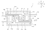
- FIG. 2 is a schematic plan view of a solid oxide fuel cell module according to one embodiment of the present invention.
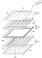
- FIG. 3 is a schematic exploded perspective view of a power generation cell of a fuel cell according to an embodiment of the present invention.
- FIG. 1 is a schematic block diagram of a solid oxide fuel cell module according to this embodiment.
- FIG. 2 is a schematic plan view of the solid oxide fuel cell module according to the present embodiment.
- a solid oxide fuel cell module (also referred to as a hot module) 1 includes a combustion chamber 11 surrounded by a heat insulating material 10.
- a heater (not shown) is disposed in the combustion chamber 11. This heater can raise the temperature in the combustion chamber 11.
- the heater may be either an electric heater or a gas burner.
- the solid oxide fuel cell module 1 further includes a plurality of power generation units.
- a plurality of power generation units In the present embodiment, an example in which the solid oxide fuel cell module 1 includes first and second power generation units 2a and 2b will be described.
- Each of the first and second power generation units 2a and 2b includes fuel cells 20a and 20b, fuel gas passages 12a and 12b, oxidant gas passages 13a and 13b, and oxidant gas preheating portions 17a and 17b. .
- the fuel cells 20 a and 20 b are arranged in the combustion chamber 11.
- the fuel cells 20a and 20b generate power by supplying fuel gas and oxidant gas.
- the fuel cells 20a and 20b are connected with fuel gas passages 12a and 12b and oxidant gas passages 13a and 13b.
- the fuel gas passages 12a and 12b are for supplying fuel gas to the fuel cells 20a and 20b. At least a part of the fuel gas passages 12 a and 12 b is disposed in the combustion chamber 11.
- the oxidant gas channels 13a and 13b are for supplying oxidant gas to the fuel cells 20a and 20b. At least a part of the oxidant gas flow paths 13 a and 13 b is disposed in the combustion chamber 11.
- Reformers 14a and 14b are provided in the fuel gas passages 12a and 12b.
- the reformers 14 a and 14 b are disposed in the combustion chamber 11.
- the reformer 14a of the first power generation unit 2a is disposed on the x2 side of the fuel cell 20a.
- the reformer 14b of the second power generation unit 2b is disposed on the x1 side of the fuel cell 20b.
- Reformation for supplying reforming water to a portion upstream of the reformers 14a, 14b of the fuel gas flow paths 12a, 12b (on the side opposite to the fuel cells 20a, 20b in the flow direction of the fuel gas).
- the water flow paths 15a and 15b are connected. At least a part of the reforming water channels 15 a and 15 b is disposed in the combustion chamber 11.
- fuel gas preheating parts 16 a, 16 b are disposed on the downstream side of the reformers 14 a, 14 b of the fuel gas passages 12 a, 12 b (on the fuel cells 20 a, 20 b side in the fuel gas flow direction). Is provided.
- the fuel gas preheating portion 16a of the first power generation unit 2a is disposed on the x2 side of the fuel cell 20a.
- the fuel gas preheating unit 16a is disposed between the fuel cell 20a and the reformer 14a in the x direction.
- the fuel gas preheating unit 16b of the second power generation unit 2b is disposed on the x1 side of the fuel cell 20b.
- the fuel gas preheating unit 16b is disposed between the fuel cell 20b and the reformer 14b in the x direction.
- oxidant gas preheating portions 17a and 17b are provided in the oxidant gas flow paths 13a and 13b.
- the oxidant gas preheating units 17a and 17b preheat the oxidant gas supplied to the fuel cells 20a and 20b.
- the combustion chamber 11 is divided into a first combustion chamber 11a1 and a second combustion chamber 11a2 by a partition member 22.
- the first power generation unit 2a is disposed in the first combustion chamber 11a1.
- the second power generation unit 2b is disposed in the second combustion chamber 11a2. For this reason, the region where the first power generation unit 2 a of the combustion chamber 11 is provided and the region where the second power generation unit 2 b of the combustion chamber 11 is provided are partitioned by the partition member 22.
- the partition member 22 is comprised with the heat insulating material.
- the heat insulating material preferably used include, for example, ceramic fiber heat insulating material, alumina fiber heat insulating material, zirconia-based ceramics and bricks having low thermal conductivity, and microporous heat insulating material having excellent heat insulating performance. Examples include those having a certain degree of strength, such as those sandwiched by ceramic plates.
- FIG. 3 is a schematic exploded perspective view of the power generation cell of the fuel cell in the present embodiment. Next, the configuration of the fuel cells 20a and 20b will be described with reference to FIG.
- the fuel cells 20 a and 20 b have one or a plurality of power generation cells 21.
- the power generation cell 21 includes a first separator 50, a power generation element 46, and a second separator 40.
- the first separator 50, the power generation element 46, and the second separator 40 are stacked in this order.
- Each separator is provided with a via hole electrode 51a for extracting generated electricity.
- a current collecting rod (not shown) for collecting and drawing electricity is provided above the uppermost separator and below the lowermost separator.
- the power generation cell 21 includes an oxidant gas manifold 45 connected to the oxidant gas flow paths 13a and 13b, and a fuel gas manifold 44 connected to the fuel gas flow paths 12a and 12b.
- the power generation element 46 is supplied from the oxidant gas manifold 45 via the oxidant gas flow paths 13a and 13b and supplied from the fuel gas manifold 44 via the fuel gas flow paths 12a and 12b. This is the part where the generated fuel reacts to generate electricity.
- the power generation element 46 includes a solid oxide electrolyte layer 47. It is preferable that the solid oxide electrolyte layer 47 has high ionic conductivity.
- the solid oxide electrolyte layer 47 can be formed of, for example, stabilized zirconia or partially stabilized zirconia. Specific examples of the stabilized zirconia include yttria stabilized zirconia (YSZ), scandia stabilized zirconia (ScSZ), and the like. Specific examples of the partially stabilized zirconia include yttria partially stabilized zirconia (YSZ), scandia partially stabilized zirconia (ScSZ), and the like.
- the solid oxide electrolyte layer 47 is, for example, Sm and Gd or the like ceria oxides doped, a LaGaO 3 as a host, La 0 the part of the La and Ga was substituted with Sr and Mg, respectively. It can also be formed of a perovskite oxide such as 8 Sr 0.2 Ga 0.8 Mg 0.2 O (3- ⁇ ) .
- the solid oxide electrolyte layer 47 is sandwiched between the air electrode layer 49 and the fuel electrode layer 48. That is, the air electrode layer 49 is formed on one main surface of the solid oxide electrolyte layer 47, and the fuel electrode layer 48 is formed on the other main surface.
- the air electrode layer 49 has an air electrode 49a.
- the air electrode 49a is a cathode. In the air electrode 49a, oxygen takes in electrons and oxygen ions are formed.
- the air electrode 49a is preferably porous, has high electron conductivity, and does not easily cause a solid-solid reaction with the solid oxide electrolyte layer 47 and the like at a high temperature.
- the air electrode 49a can be formed of, for example, scandia-stabilized zirconia (ScSZ), indium oxide doped with Sn, PrCoO 3 oxide, LaCoO 3 oxide, LaMnO 3 oxide, or the like.
- LaMnO 3 -based oxide examples include La 0.8 Sr 0.2 MnO 3 (common name: LSM), La 0.6 Ca 0.4 MnO 3 (common name: LCM), and the like.
- the air electrode 49a may be made of a mixed material in which two or more of the above materials are mixed.
- the fuel electrode layer 48 has a fuel electrode 48a.
- the fuel electrode 48a is an anode. In the fuel electrode 48a, oxygen ions and the fuel react to emit electrons.
- the fuel electrode 48a is preferably porous, has high ionic conductivity, and does not easily cause a solid-solid reaction with the solid oxide electrolyte layer 47 and the like at a high temperature.
- the fuel electrode 48a can be composed of, for example, NiO, yttria-stabilized zirconia (YSZ) / nickel metal porous cermet, scandia-stabilized zirconia (ScSZ) / nickel metal porous cermet, or the like.
- the fuel electrode layer 48 may be made of a mixed material obtained by mixing two or more of the above materials.
- first separator 50 Below the air electrode layer 49 of the power generation element 46, a first separator 50 configured by a first separator body 51 and a first flow path forming member 52 is disposed.
- the first separator 50 is formed with an oxidant gas supply path 53 for supplying air to the air electrode 49a.
- the oxidant gas supply path 53 extends from the oxidant gas manifold 45 toward the x2 side from the x1 side in the x direction.
- the opening of the oxidant gas supply path 53 constitutes a plurality of first exhaust ports 53a through which the air electrode side exhaust gas, which is an oxidant gas used for power generation, is discharged.
- the first exhaust port 53a is provided on the side wall on the y2 side of the fuel cells 20a, 20b. Therefore, the air electrode side exhaust gas is discharged from the fuel cells 20a and 20b toward the y2 side.
- the constituent material of the first separator 50 is not particularly limited.
- the first separator 50 can be formed of, for example, stabilized zirconia such as yttria stabilized zirconia, partially stabilized zirconia, or the like.
- the second separator 40 On the fuel electrode layer 48 of the power generation element 46, the second separator 40 constituted by the second separator body 41 and the second flow path forming member 42 is disposed.
- the second separator 40 is formed with a fuel gas supply passage 43 for supplying fuel to the fuel electrode 48a.
- the fuel gas supply path 43 extends from the fuel gas manifold 44 toward the y2 side from the y1 side in the y direction.
- the opening of the fuel gas supply path 43 constitutes a plurality of second exhaust ports 43a through which fuel electrode side exhaust gas, which is fuel gas used for power generation, is discharged.
- the second exhaust port 43a is provided on the side wall on the x2 side of the fuel cells 20a, 20b.
- the fuel electrode side exhaust gas is discharged from the fuel cells 20a and 20b toward the x2 side.
- the direction rotated forward by 90 ° with respect to the discharge direction of the air electrode side exhaust gas is set as the discharge direction of the fuel electrode side exhaust gas.
- the constituent material of the second separator 40 is not particularly limited.
- the second separator 40 can be formed of, for example, stabilized zirconia, partially stabilized zirconia, or the like.
- the combustion chamber 11 includes discharge ports 11 c 1 and 11 c 2. Specifically, the discharge port 11c1 is provided in the first combustion chamber 11a1.
- the exhaust port 11c1 is for exhausting the exhaust gas including the air electrode side exhaust gas and the fuel electrode side exhaust gas discharged from the fuel cell 20a to the outside of the first combustion chamber 11a1.
- the exhaust gas discharged from the discharge port 11c1 is discharged out of the solid oxide fuel cell module 1 via the combustion chamber external heat exchanger 54a provided outside the combustion chamber 11.
- the discharge port 11c1 is formed on the inner surface on the x1 side of the first combustion chamber 11a1.
- the discharge port 11c1 is directed toward the opposite side (x1 side) of the exhaust gas discharge direction of the second exhaust port 43a of the fuel cell 20a. It is open.
- the discharge port 11c2 is provided in the second combustion chamber 11a2.
- the discharge port 11c2 is for discharging the exhaust gas containing the air electrode side exhaust gas and the fuel electrode side exhaust gas discharged from the fuel cell 20b to the outside of the second combustion chamber 11a2.
- the exhaust gas discharged from the discharge port 11c2 is discharged out of the solid oxide fuel cell module 1 via the combustion chamber external heat exchanger 54b provided outside the combustion chamber 11.
- the discharge port 11c2 is formed on the inner surface on the x2 side of the second combustion chamber 11a2.
- the discharge port 11c2 faces toward the opposite side (x2 side) to the exhaust gas discharge direction of the second exhaust port 43a of the fuel cell 20b. It is open.
- the first combustion chamber 11a1 is formed with a discharge passage 11b1 that communicates the first exhaust port 53a and the second exhaust port 43a of the fuel cell 20a with the first discharge port 11c1.
- the exhaust passage 11b1 is configured such that a part of the space of the first combustion chamber 11a1 serves as a passage.
- the discharge channel 11b1 is provided such that at least a part of the oxidant gas preheating portion 17a is located on the discharge channel 11b1 or faces the discharge channel 11b1.
- the discharge channel 11b1 is provided so that at least a part of the oxidant gas preheating portion 17a is located on the discharge channel 11b1.
- a discharge passage 11b2 is formed which communicates the first exhaust port 53a and the second exhaust port 43a of the fuel cell 20b with the second exhaust port 11c2.
- the exhaust passage 11b2 is configured such that a part of the second combustion chamber 11a2 is a passage.
- the discharge channel 11b2 is provided such that at least a part of the oxidant gas preheating portion 17b is located on the discharge channel 11b2 or faces the discharge channel 11b2.
- the discharge channel 11b2 is provided so that at least a part of the oxidant gas preheating portion 17b is located on the discharge channel 11b2.
- the first and second power generation units 2a and 2b are arranged such that the fuel cell 20a and the oxidant gas preheating unit 17a are adjacent to each other, and the fuel cell 20b and the oxidant gas preheating unit 17b are adjacent to each other.
- the fuel cell 20a and the fuel cell 20b are arranged so that the fuel cell 20a and the fuel cell 20b overlap when viewed from the x direction.
- the fuel cell 20a of the first power generation unit 2a is located closer to the x2 side in the x direction (first direction) than the fuel cell 20b of the second power generation unit 2b.
- the oxidant gas preheating part 17a connected to the fuel cell 20a is drawn out of the combustion chamber 11a1 via the combustion chamber located on the y1 side in the y direction of the fuel cell 20b. For this reason, the oxidant gas preheating portion 17a and the fuel cell 20b are adjacent to each other in the y direction (second direction) perpendicular to the x direction.
- the oxidant gas preheating part 17b connected to the fuel cell 20b is drawn out of the combustion chamber 11a2 via the combustion chamber located on the y2 side in the y direction of the fuel cell 20b. Therefore, the oxidant gas preheating unit 17b and the fuel cell 20a are adjacent to each other in the y direction (second direction) perpendicular to the x direction.
- the region of the combustion chamber 11 where the fuel cell 20 a is disposed and the region of the combustion chamber 11 where the fuel cell 20 b is disposed are partitioned by a partition member 22. Further, the region in which the fuel cell 20 a of the combustion chamber 11 is disposed and the region in which the oxidant gas preheating portion 17 b connected to the fuel cell 20 b of the combustion chamber 11 is disposed are partitioned by the partition member 22. The region of the combustion chamber 11 where the fuel cell 20 b is disposed and the region of the combustion chamber 11 where the oxidant gas preheating portion 17 a connected to the fuel cell 20 a is disposed are partitioned by the partition member 22.
- the partition member 22 is located between the fuel cell 20a and the fuel cell 20b, between the fuel cell 20a and the oxidant gas preheating portion 17b, and between the fuel cell 20b and the oxidant gas preheating portion 17a. At least provided in between.
- raw fuel gas before reforming is supplied to the fuel gas passages 12a and 12b.
- reforming water is supplied to the reforming water channels 15a and 15b.
- the reforming water is vaporized by the vaporizers 55a and 55b located in the combustion chambers 11a1 and 11a2 of the reforming water flow paths 15a and 15b, and becomes steam.
- This steam and raw fuel gas are supplied to the reformers 14a and 14b.
- the raw fuel gas is reformed by the steam to generate the reformed fuel gas.
- the reformed fuel gas is further heated by the fuel gas preheating units 16a and 16b.
- the heated reformed fuel gas is supplied to the fuel cells 20a and 20b.
- fuel gas is a general term for raw fuel gas and reformed fuel gas. That is, the fuel gas includes raw fuel gas and reformed fuel gas.
- Oxidant gases such as oxygen and air are supplied to the oxidant gas flow paths 13a and 13b.
- the oxidant gas is heated in the combustion chamber external heat exchangers 54a and 54b and the oxidant gas preheating sections 17a and 17b, and then supplied to the fuel cells 20a and 20b.
- the fuel cells 20a and 20b perform power generation using the supplied reformed fuel gas and oxidant gas.
- the fuel electrode side exhaust gas which is the reformed fuel gas used for power generation in the fuel cells 20a, 20b, is exhausted outside the fuel cells 20a, 20b from the second exhaust ports 43a of the fuel cells 20a, 20b.
- the air electrode side exhaust gas which is the oxidant gas used for power generation in the fuel cells 20a, 20b, is exhausted outside the fuel cells 20a, 20b from the first exhaust ports 53a of the fuel cells 20a, 20b. .
- the fuel electrode side exhaust gas and the air electrode side exhaust gas are discharged to the outside of the combustion chambers 11a1 and 11a2 via the discharge passages 11b1 and 11b2, and are further solid-oxidized via the combustion chamber external heat exchangers 54a and 54b. It is discharged out of the physical fuel cell module 1.
- the fuel electrode side exhaust gas contains carbon monoxide and the like. Further, the air electrode side exhaust gas contains oxygen. For this reason, when the fuel electrode side exhaust gas and the air electrode side exhaust gas are mixed in the combustion chambers 11a1 and 11a2 at high temperatures, the fuel electrode side exhaust gas is completely burned. Thereby, combustion gas is generated. Therefore, the exhaust gas discharged to the outside of the combustion chambers 11a1 and 11a2 via the discharge passages 11b1 and 11b2 includes the combustion gas and a portion that is not used for generating the combustion gas of the air electrode side exhaust gas.
- exhaust gas includes fuel electrode side exhaust gas, air electrode side exhaust gas, and combustion gas.
- the first and second power generation units 2a and 2b are configured such that the fuel cell 20a and the oxidant gas preheating unit 17b connected to the fuel cell 20b are adjacent in the y direction, and the fuel cell 20b.
- the oxidant gas preheating part 17a connected to the fuel cell 20a is arranged adjacent to each other in the y direction. For this reason, for example, the fuel cell module 1 can be reduced in size compared with the case where large fuel cells are arranged adjacent to each other in the y direction.
- the fuel cell 20a and the fuel cell 20b are arranged at different positions in the x direction, and are arranged so as to overlap when viewed from the x direction. Therefore, the solid oxide fuel cell module 1 can be further downsized.
- the fuel cell 20a and the oxidant gas preheating part 17b through which the low-temperature oxidant gas flows are adjacent to each other.
- the fuel cell 20b and the oxidant gas preheating portion 17a through which the low-temperature oxidant gas flows are adjacent to each other.
- the fuel cells 20a and 20b are cooled by the oxidant gas preheating portions 17b and 17a, respectively, and the temperature of the fuel cells 20a and 20b tends to be lowered.
- the portions near the oxidant gas preheating portions 17b and 17a of the fuel cells 20a and 20b have a lower temperature than the other portions, and temperature unevenness is likely to occur in the fuel cells 20a and 20b. Therefore, the power generation of the fuel cells 20a and 20b may become unstable.
- the partition member 22 oxidizes gas preheating portions 17a and 17b connected to the region where one of the fuel cells 20a and 20b of the combustion chamber 11 is disposed and the other of the fuel cells 20a and 20b.
- the area where the is placed is partitioned. For this reason, heat exchange between the fuel cells 20a, 20b and the oxidant gas preheating portions 17b, 17a arranged adjacent to each other can be suppressed. Accordingly, it is possible to suppress the temperature decrease and the temperature unevenness of the fuel cells 20a and 20b. As a result, power generation by the fuel cells 20a and 20b can be stabilized.
- the heat insulating function of the partition member 22 is high. Therefore, it is preferable that the partition member 22 is comprised with the heat insulating material.
- the discharge flow paths 11b1 and 11b2 are such that part of the oxidant gas preheating portions 17a and 17b are located on the discharge flow paths 11b1 and 11b2 or face the discharge flow paths 11b1 and 11b2. It is provided as follows. Further, the discharge passages 11b1 and 11b2 are configured such that at least a part of the reformers 14a and 14b and at least a part of the fuel gas preheating parts 16a and 16b are located on the discharge passages 11b1 and 11b2. It is provided so as to face the flow paths 11b1 and 11b2.
- the units 14a and 14b and the fuel gas preheating parts 16a and 16b are heated. Therefore, the heat of exhaust gas can be used effectively. As a result, high energy efficiency can be realized.
- the temperature of the oxidant gas preheating units 17a and 17b, the reformers 14a and 14b, and the fuel gas preheating units 16a and 16b can be increased, the oxidant gas preheating units 17a and 17b, the reformers 14a and 14b, and the fuel gas.
- the fuel cells 20a and 20b are hardly cooled by the preheating parts 16a and 16b. Therefore, the power generation by the fuel cells 20a and 20b can be further stabilized.
- both the fuel electrode side exhaust gas and the air electrode side exhaust gas are exhausted to the combustion chambers 11a1 and 11a2, mixed in the middle of the discharge passages 11b1 and 11b2, and burned. For this reason, the temperature of the exhaust gas flowing through the discharge passages 11b1 and 11b2 is high. Therefore, the reformers 14a and 14b, the fuel gas preheating units 16a and 16b, and the oxidant gas preheating units 17a and 17b can be more efficiently heated using the exhaust gas. Therefore, higher energy efficiency can be realized.
- the fuel electrode side exhaust gas and the air electrode side exhaust gas can be reliably mixed and combusted in the discharge passages 11b1 and 11b2. Thereby, it can suppress more effectively that carbon monoxide is discharged
- the air electrode side exhaust gas can be mixed with the fuel electrode side exhaust gas at an arbitrary position after flowing along the partition member 22.
- a combustion position can be set in the vicinity of the reformer or preheater to which much heat is to be applied, and the heat utilization rate by the exhaust gas can be improved.
- the solid oxide fuel cell module 1 including the two power generation units 2a and 2b has been described.
- the number of power generation units included in the solid oxide fuel cell module is not particularly limited as long as it is plural.
- the solid oxide fuel cell module according to the present invention may include three or more, for example, four power generation units.
Landscapes
- Engineering & Computer Science (AREA)
- Chemical & Material Sciences (AREA)
- Life Sciences & Earth Sciences (AREA)
- Manufacturing & Machinery (AREA)
- Sustainable Development (AREA)
- Sustainable Energy (AREA)
- Chemical Kinetics & Catalysis (AREA)
- Electrochemistry (AREA)
- General Chemical & Material Sciences (AREA)
- Combustion & Propulsion (AREA)
- Fuel Cell (AREA)
Abstract
小型でありつつ、安定的に発電を行うことができる固体酸化物形燃料電池モジュールを提供する。 複数の発電ユニット2a、2bは、一の燃料電池20aと、当該一の燃料電池20aに隣接する他の燃料電池20bに接続された酸化剤ガス予熱部17bとが隣り合うように配されている。固体酸化物形燃料電池モジュール1は、区画部材22を備えている。区画部材22は、燃焼室11の一の燃料電池20aが配された領域と、他の燃料電池20bが配された領域とを区画すると共に、一の燃料電池20aが配された領域と、他の燃料電池20bに接続された酸化剤ガス予熱部17bが配された領域とを区画している。
Description
本発明は、燃料電池モジュールに関する。特に、本発明は、固体酸化物形燃料電池モジュールに関する。
近年、新たなエネルギー源として、燃料電池モジュールに対する注目が大きくなってきている。燃料電池モジュールには、例えば下記の特許文献1に記載のような固体酸化物形燃料電池(SOFC:Solid Oxide Fuel Cell)モジュール、溶融塩燃料電池モジュール、リン酸型燃料電池モジュール、高分子固体電解質燃料電池モジュール等がある。これらの燃料電池モジュールの中でも、固体酸化物形燃料電池モジュールでは、液体の構成要素を用いる必要が必ずしもなく、炭化水素燃料を用いるときにも外部に改質器を設ける必要がない。このため、固体酸化物形燃料電池モジュールに対する研究開発が盛んに行われている。
固体酸化物形燃料電池モジュールには、燃料電池の温度むらを小さくし、固体酸化物形燃料電池モジュールを安定的に動作させたいという要望がある。また、固体酸化物形燃料電池モジュールには、小型化したいという要望もある。
本発明は、斯かる点に鑑みてなされたものであり、その目的は、小型でありつつ、安定的に発電を行うことができる固体酸化物形燃料電池モジュールを提供することにある。
本発明に係る燃料電池モジュールは、燃焼室と、複数の発電ユニットとを備えている。複数の発電ユニットのそれぞれは、燃料電池と、燃料ガス流路と、酸化剤ガス流路と、酸化剤ガス予熱部とを有する。燃料電池は、燃焼室内に配置されている。燃料電池は、燃料ガスと酸化剤ガスとが供給されることにより発電する。燃料ガス流路は、燃料電池に燃料ガスを供給する。酸化剤ガス流路は、燃料電池に酸化剤ガスを供給する。酸化剤ガス予熱部は、燃焼室内において、酸化剤ガス流路中に設けられている。酸化剤ガス予熱部は、酸化剤ガスを予熱する。複数の発電ユニットは、一の燃料電池と、当該一の燃料電池に隣接する他の燃料電池に接続された酸化剤ガス予熱部とが隣り合うように配されている。本発明に係る燃料電池モジュールは、区画部材をさらに備える。区画部材は、燃焼室の一の燃料電池が配された領域と、他の燃料電池が配された領域とを区画すると共に、一の燃料電池が配された領域と、他の燃料電池に接続された酸化剤ガス予熱部が配された領域とを区画している。
本発明に係る燃料電池モジュールのある特定の局面では、複数の発電ユニットは、第1及び第2の発電ユニットにより構成されている。第1の発電ユニットの燃料電池は、第2の発電ユニットの燃料電池よりも第1の方向の一方側に位置している。第1の発電ユニットの燃料電池と第2の発電ユニットの酸化剤ガス予熱部とは第1の方向に対して垂直な第2の方向において隣り合っている。第2の発電ユニットの燃料電池と第1の発電ユニットの酸化剤ガス予熱部とは第2の方向において隣り合っている。
本発明に係る燃料電池モジュールの他の特定の局面では、第1の方向から視た際に、第1及び第2の燃料電池は、第1の発電ユニットの燃料電池と第2の発電ユニットの燃料電池とが重なるように配されている。
本発明に係る燃料電池モジュールの別の特定の局面では、区画部材は、断熱材により構成されている。
本発明に係る燃料電池モジュールのさらに他の特定の局面では、燃料電池は、第1の排気口と、第2の排気口とを有する。第1の排気口は、発電に使用済みの酸化剤ガスである空気極側排気ガスを排気する。第2の排気口は、発電に使用済みの燃料ガスである燃料極側排気ガスを排気する。燃焼室は、排出口と、排出流路とを有する。排出口は、燃料電池から排気された排気ガスを燃焼室外に排出する。排出流路は、第1及び第2の排気口と排出口とを接続している。排出流路は、酸化剤ガス予熱部の少なくとも一部が、排出流路上に位置するか、または排出流路に面するように設けられている。
本発明によれば、小型でありつつ、安定的に発電を行うことができる固体酸化物形燃料電池モジュールを提供することができる。
以下、本発明を実施した好ましい形態の一例について説明する。但し、下記の実施形態は、単なる例示である。本発明は、下記の実施形態に何ら限定されない。
また、実施形態等において参照する各図面において、実質的に同一の機能を有する部材は同一の符号で参照することとする。また、実施形態等において参照する図面は、模式的に記載されたものであり、図面に描画された物体の寸法の比率などは、現実の物体の寸法の比率などとは異なる場合がある。図面相互間においても、物体の寸法比率等が異なる場合がある。具体的な物体の寸法比率等は、以下の説明を参酌して判断されるべきである。
(固体酸化物形燃料電池モジュール1の構成)
図1は、本実施形態に係る固体酸化物形燃料電池モジュールの略図的ブロック図である。図2は、本実施形態に係る固体酸化物形燃料電池モジュールの模式的平面図である。
図1は、本実施形態に係る固体酸化物形燃料電池モジュールの略図的ブロック図である。図2は、本実施形態に係る固体酸化物形燃料電池モジュールの模式的平面図である。
固体酸化物形燃料電池モジュール(ホットモジュールともいう。)1は、断熱材10により包囲された燃焼室11を備えている。燃焼室11内には、図示しないヒーターが配されている。このヒーターにより燃焼室11内の昇温が可能となっている。なお、ヒーターは電気ヒーター、ガスバーナーのどちらでもよい。
固体酸化物形燃料電池モジュール1は、複数の発電ユニットをさらに備えている。本実施形態では、固体酸化物形燃料電池モジュール1が、第1及び第2の発電ユニット2a、2bを備える例について説明する。
第1及び第2の発電ユニット2a、2bのそれぞれは、燃料電池20a、20b、燃料ガス流路12a、12b、酸化剤ガス流路13a、13b、酸化剤ガス予熱部17a、17bを備えている。燃料電池20a、20bは、燃焼室11内に配されている。燃料電池20a、20bは、燃料ガスと酸化剤ガスとが供給されることにより発電する。
燃料電池20a、20bには、燃料ガス流路12a、12bと、酸化剤ガス流路13a、13bとが接続されている。燃料ガス流路12a、12bは、燃料電池20a、20bに燃料ガスを供給するためのものである。燃料ガス流路12a、12bの少なくとも一部は、燃焼室11内に配置されている。酸化剤ガス流路13a、13bは、燃料電池20a、20bに酸化剤ガスを供給するためのものである。酸化剤ガス流路13a、13bの少なくとも一部は、燃焼室11内に配置されている。
燃料ガス流路12a、12b中には、改質器14a、14bが設けられている。改質器14a、14bは、燃焼室11内に配置されている。図2に示すように、第1の発電ユニット2aの改質器14aは、燃料電池20aのx2側に配されている。第2の発電ユニット2bの改質器14bは、燃料電池20bのx1側に配されている。
燃料ガス流路12a、12bの改質器14a、14bよりも上流側(燃料ガスの流れる方向において燃料電池20a、20bとは反対側)の部分には、改質用水を供給するための改質用水流路15a、15bが接続されている。改質用水流路15a、15bの少なくとも一部は、燃焼室11内に配されている。
燃焼室11内において、燃料ガス流路12a、12bの改質器14a、14bよりも下流側(燃料ガスの流れる方向において燃料電池20a、20b側)の部分には、燃料ガス予熱部16a、16bが設けられている。図2に示すように、第1の発電ユニット2aの燃料ガス予熱部16aは、燃料電池20aのx2側に配されている。燃料ガス予熱部16aは、x方向において、燃料電池20aと改質器14aとの間に配されている。第2の発電ユニット2bの燃料ガス予熱部16bは、燃料電池20bのx1側に配されている。燃料ガス予熱部16bは、x方向において、燃料電池20bと改質器14bとの間に配されている。
燃焼室11内において、酸化剤ガス流路13a、13b中には、酸化剤ガス予熱部17a、17bが設けられている。酸化剤ガス予熱部17a、17bは、燃料電池20a、20bに供給される酸化剤ガスを予熱する。
本実施形態では、燃焼室11は、区画部材22により、第1の燃焼室11a1と第2の燃焼室11a2とに区画されている。第1の発電ユニット2aは、第1の燃焼室11a1に配置されている。第2の発電ユニット2bは、第2の燃焼室11a2に配置されている。このため、燃焼室11の第1の発電ユニット2aが設けられている領域と、燃焼室11の第2の発電ユニット2bが設けられている領域とは、区画部材22により区画されている。
なお、区画部材22は、断熱材により構成されていることが好ましい。好ましく用いられる断熱材の具体例としては、例えば、セラミックファイバー系断熱材、アルミナファイバー系断熱材、ジルコニア系の熱伝導率の低いセラミックスやレンガ、断熱性能に優れたマイクロポーラス系断熱材をレンガやセラミック板で狭持したものなど、ある程度以上の強度を有するものが挙げられる。
(燃料電池20a、20b)
図3は、本実施形態における燃料電池の発電セルの略図的分解斜視図である。次に、図3を参照しながら、燃料電池20a、20bの構成について説明する。
図3は、本実施形態における燃料電池の発電セルの略図的分解斜視図である。次に、図3を参照しながら、燃料電池20a、20bの構成について説明する。
燃料電池20a、20bは、1または複数の発電セル21を有する。発電セル21は、第1のセパレータ50と、発電要素46と、第2のセパレータ40とを有する。発電セル21では、第1のセパレータ50と、発電要素46と、第2のセパレータ40とがこの順番で積層されている。各セパレータには発生した電気を引き出すためのビアホール電極51aが設けられている。また、最上部のセパレータの上および最下部のセパレータの下には、電気を集めて引き出すための集電棒(図示省略)が設けられている。
発電セル21は、酸化剤ガス流路13a、13bに接続されている酸化剤ガス用マニホールド45と、燃料ガス流路12a、12bに接続されている燃料ガス用マニホールド44とを有する。
(発電要素46)
発電要素46は、酸化剤ガス流路13a、13bを経由して酸化剤ガス用マニホールド45から供給される酸化剤ガスと、燃料ガス流路12a、12bを経由して燃料ガス用マニホールド44から供給される燃料とが反応し、発電が行われる部分である。
発電要素46は、酸化剤ガス流路13a、13bを経由して酸化剤ガス用マニホールド45から供給される酸化剤ガスと、燃料ガス流路12a、12bを経由して燃料ガス用マニホールド44から供給される燃料とが反応し、発電が行われる部分である。
(固体酸化物電解質層47)
発電要素46は、固体酸化物電解質層47を備えている。固体酸化物電解質層47は、イオン導電性が高いものであることが好ましい。固体酸化物電解質層47は、例えば、安定化ジルコニアや、部分安定化ジルコニアなどにより形成することができる。安定化ジルコニアの具体例としは、イットリア安定化ジルコニア(YSZ)、スカンジア安定化ジルコニア(ScSZ)等が挙げられる。部分安定化ジルコニアの具体例としは、イットリア部分安定化ジルコニア(YSZ)、スカンジア部分安定化ジルコニア(ScSZ)等が挙げられる。また、固体酸化物電解質層47は、例えば、SmやGd等がドープされたセリア系酸化物や、LaGaO3を母体とし、LaとGaとの一部をそれぞれSr及びMgで置換したLa0.8Sr0.2Ga0.8Mg0.2O(3-δ)などのペロブスカイト型酸化物などにより形成することもできる。
発電要素46は、固体酸化物電解質層47を備えている。固体酸化物電解質層47は、イオン導電性が高いものであることが好ましい。固体酸化物電解質層47は、例えば、安定化ジルコニアや、部分安定化ジルコニアなどにより形成することができる。安定化ジルコニアの具体例としは、イットリア安定化ジルコニア(YSZ)、スカンジア安定化ジルコニア(ScSZ)等が挙げられる。部分安定化ジルコニアの具体例としは、イットリア部分安定化ジルコニア(YSZ)、スカンジア部分安定化ジルコニア(ScSZ)等が挙げられる。また、固体酸化物電解質層47は、例えば、SmやGd等がドープされたセリア系酸化物や、LaGaO3を母体とし、LaとGaとの一部をそれぞれSr及びMgで置換したLa0.8Sr0.2Ga0.8Mg0.2O(3-δ)などのペロブスカイト型酸化物などにより形成することもできる。
固体酸化物電解質層47は、空気極層49と燃料極層48とにより挟持されている。すなわち、固体酸化物電解質層47の一主面の上に空気極層49が形成されており、他主面の上に燃料極層48が形成されている。
(空気極層49)
空気極層49は、空気極49aを有する。空気極49aは、カソードである。空気極49aにおいては、酸素が電子を取り込んで、酸素イオンが形成される。空気極49aは、多孔質で、電子伝導率が高く、かつ、高温において固体酸化物電解質層47等と固体間反応を起こしにくいものであることが好ましい。空気極49aは、例えば、スカンジア安定化ジルコニア(ScSZ)、Snをドープした酸化インジウム、PrCoO3系酸化物、LaCoO3系酸化物、LaMnO3系酸化物などにより形成することができる。LaMnO3系酸化物の具体例としては、例えば、La0.8Sr0.2MnO3(通称:LSM)や、La0.6Ca0.4MnO3(通称:LCM)等が挙げられる。空気極49aは、上記材料の2種以上を混合した混合材料により構成されていてもよい。
空気極層49は、空気極49aを有する。空気極49aは、カソードである。空気極49aにおいては、酸素が電子を取り込んで、酸素イオンが形成される。空気極49aは、多孔質で、電子伝導率が高く、かつ、高温において固体酸化物電解質層47等と固体間反応を起こしにくいものであることが好ましい。空気極49aは、例えば、スカンジア安定化ジルコニア(ScSZ)、Snをドープした酸化インジウム、PrCoO3系酸化物、LaCoO3系酸化物、LaMnO3系酸化物などにより形成することができる。LaMnO3系酸化物の具体例としては、例えば、La0.8Sr0.2MnO3(通称:LSM)や、La0.6Ca0.4MnO3(通称:LCM)等が挙げられる。空気極49aは、上記材料の2種以上を混合した混合材料により構成されていてもよい。
(燃料極層48)
燃料極層48は、燃料極48aを有する。燃料極48aは、アノードである。燃料極48aにおいては、酸素イオンと燃料とが反応して電子を放出する。燃料極48aは、多孔質で、イオン伝導性が高く、かつ、高温において固体酸化物電解質層47等と固体間反応を起こしにくいものであることが好ましい。燃料極48aは、例えば、NiO、イットリア安定化ジルコニア(YSZ)・ニッケル金属の多孔質サーメットや、スカンジア安定化ジルコニア(ScSZ)・ニッケル金属の多孔質サーメット等により構成することができる。燃料極層48は、上記材料の2種以上を混合した混合材料により構成されていてもよい。
燃料極層48は、燃料極48aを有する。燃料極48aは、アノードである。燃料極48aにおいては、酸素イオンと燃料とが反応して電子を放出する。燃料極48aは、多孔質で、イオン伝導性が高く、かつ、高温において固体酸化物電解質層47等と固体間反応を起こしにくいものであることが好ましい。燃料極48aは、例えば、NiO、イットリア安定化ジルコニア(YSZ)・ニッケル金属の多孔質サーメットや、スカンジア安定化ジルコニア(ScSZ)・ニッケル金属の多孔質サーメット等により構成することができる。燃料極層48は、上記材料の2種以上を混合した混合材料により構成されていてもよい。
(第1のセパレータ50)
発電要素46の空気極層49の下には、第1のセパレータ本体51と、第1の流路形成部材52とにより構成されている第1のセパレータ50が配置されている。第1のセパレータ50には、空気極49aに空気を供給するための酸化剤ガス供給路53が形成されている。図3に示すとおり、この酸化剤ガス供給路53は、酸化剤ガス用マニホールド45からx方向のx1側からx2側に向かって延びている。酸化剤ガス供給路53の開口は、発電に使用済みの酸化剤ガスである空気極側排気ガスを排出する複数の第1の排気口53aを構成している。図2に示すように、第1の排気口53aは、燃料電池20a、20bのy2側の側壁に設けられている。よって、空気極側排気ガスは、燃料電池20a、20bからy2側に向かって排出される。
発電要素46の空気極層49の下には、第1のセパレータ本体51と、第1の流路形成部材52とにより構成されている第1のセパレータ50が配置されている。第1のセパレータ50には、空気極49aに空気を供給するための酸化剤ガス供給路53が形成されている。図3に示すとおり、この酸化剤ガス供給路53は、酸化剤ガス用マニホールド45からx方向のx1側からx2側に向かって延びている。酸化剤ガス供給路53の開口は、発電に使用済みの酸化剤ガスである空気極側排気ガスを排出する複数の第1の排気口53aを構成している。図2に示すように、第1の排気口53aは、燃料電池20a、20bのy2側の側壁に設けられている。よって、空気極側排気ガスは、燃料電池20a、20bからy2側に向かって排出される。
第1のセパレータ50の構成材料は、特に限定されない。第1のセパレータ50は、例えば、イットリア安定化ジルコニアなどの安定化ジルコニアや、部分安定化ジルコニア等により形成することができる。
(第2のセパレータ40)
発電要素46の燃料極層48の上には、第2のセパレータ本体41と、第2の流路形成部材42とにより構成されている第2のセパレータ40が配置されている。第2のセパレータ40には、燃料極48aに燃料を供給するための燃料ガス供給路43が形成されている。図3に示すように、この燃料ガス供給路43は、燃料ガス用マニホールド44からy方向のy1側からy2側に向かって延びている。燃料ガス供給路43の開口は、発電に使用済みの燃料ガスである燃料極側排気ガスを排出する複数の第2の排気口43aを構成している。図2に示すように、第2の排気口43aは、燃料電池20a、20bのx2側の側壁に設けられている。よって、燃料極側排気ガスは、燃料電池20a、20bからx2側に向かって排出される。なお、本実施形態では、空気極側排気ガスの排出方向に対し90°正回転した方向を燃料極側排気ガスの排出方向としている。
発電要素46の燃料極層48の上には、第2のセパレータ本体41と、第2の流路形成部材42とにより構成されている第2のセパレータ40が配置されている。第2のセパレータ40には、燃料極48aに燃料を供給するための燃料ガス供給路43が形成されている。図3に示すように、この燃料ガス供給路43は、燃料ガス用マニホールド44からy方向のy1側からy2側に向かって延びている。燃料ガス供給路43の開口は、発電に使用済みの燃料ガスである燃料極側排気ガスを排出する複数の第2の排気口43aを構成している。図2に示すように、第2の排気口43aは、燃料電池20a、20bのx2側の側壁に設けられている。よって、燃料極側排気ガスは、燃料電池20a、20bからx2側に向かって排出される。なお、本実施形態では、空気極側排気ガスの排出方向に対し90°正回転した方向を燃料極側排気ガスの排出方向としている。
第2のセパレータ40の構成材料は、特に限定されない。第2のセパレータ40は、例えば、安定化ジルコニアや、部分安定化ジルコニア等により形成することができる。
(排気経路)
図1に示すように、燃焼室11は、排出口11c1,11c2を備えている。具体的には、排出口11c1は、第1の燃焼室11a1に設けられている。
図1に示すように、燃焼室11は、排出口11c1,11c2を備えている。具体的には、排出口11c1は、第1の燃焼室11a1に設けられている。
排出口11c1は、燃料電池20aから排出された空気極側排気ガス及び燃料極側排気ガスを含む排気ガスを第1の燃焼室11a1外に排出するためのものである。排出口11c1から排出された排気ガスは、燃焼室11の外部に設けられた燃焼室外部熱交換器54aを経由して固体酸化物形燃料電池モジュール1外に排出される。
図2に示すように排出口11c1は、第1の燃焼室11a1のx1側の内側面に形成されている。排出口11c1は、燃料電池20aを平面視したときに(z方向から視たときに)、燃料電池20aの第2の排気口43aの排気ガスの排出方向と反対側(x1側)に向かって開口している。
排出口11c2は、第2の燃焼室11a2に設けられている。排出口11c2は、燃料電池20bから排出された空気極側排気ガス及び燃料極側排気ガスを含む排気ガスを第2の燃焼室11a2外に排出するためのものである。排出口11c2から排出された排気ガスは、燃焼室11の外部に設けられた燃焼室外部熱交換器54bを経由して固体酸化物形燃料電池モジュール1外に排出される。
図2に示すように排出口11c2は、第2の燃焼室11a2のx2側の内側面に形成されている。排出口11c2は、燃料電池20bを平面視したときに(z方向から視たときに)、燃料電池20bの第2の排気口43aの排気ガスの排出方向と反対側(x2側)に向かって開口している。
第1の燃焼室11a1には、燃料電池20aの第1の排気口53a及び第2の排気口43aと、第1の排出口11c1とを連通している排出流路11b1が形成されている。排出流路11b1は、第1の燃焼室11a1の一部の空間が通路となって構成されている。
排出流路11b1は、酸化剤ガス予熱部17aの少なくとも一部が、排出流路11b1上に位置するか、または排出流路11b1に面するように設けられている。本実施形態では、具体的には、排出流路11b1は、酸化剤ガス予熱部17aの少なくとも一部が、排出流路11b1上に位置するように設けられている。
第2の燃焼室11a2には、燃料電池20bの第1の排気口53a及び第2の排気口43aと、第2の排出口11c2とを連通している排出流路11b2が形成されている。排出流路11b2は、第2の燃焼室11a2の一部の空間が通路となって構成されている。
排出流路11b2は、酸化剤ガス予熱部17bの少なくとも一部が、排出流路11b2上に位置するか、または排出流路11b2に面するように設けられている。本実施形態では、具体的には、排出流路11b2は、酸化剤ガス予熱部17bの少なくとも一部が、排出流路11b2上に位置するように設けられている。
(第1及び第2の発電ユニット2a、2bの配置)
次に、図2を主として参照しながら、第1及び第2の発電ユニット2a、2bの配置について説明する。
次に、図2を主として参照しながら、第1及び第2の発電ユニット2a、2bの配置について説明する。
第1及び第2の発電ユニット2a、2bは、燃料電池20aと酸化剤ガス予熱部17aとが隣り合うと共に、燃料電池20bと酸化剤ガス予熱部17bとが隣り合うように配されている。
具体的には、まず、燃料電池20aと燃料電池20bとは、x方向から視た際に燃料電池20aと燃料電池20bとが重なるように配されている。第1の発電ユニット2aの燃料電池20aは、第2の発電ユニット2bの燃料電池20bよりもx方向(第1の方向)のx2側に位置している。
燃料電池20aに接続されている酸化剤ガス予熱部17aは、燃料電池20bのy方向のy1側に位置する燃焼室内を経由して燃焼室11a1外にまで引き出されている。このため、酸化剤ガス予熱部17aと燃料電池20bとは、x方向に対して垂直なy方向(第2の方向)において隣り合っている。
燃料電池20bに接続されている酸化剤ガス予熱部17bは、燃料電池20bのy方向のy2側に位置する燃焼室内を経由して燃焼室11a2外にまで引き出されている。このため、酸化剤ガス予熱部17bと燃料電池20aとは、x方向に対して垂直なy方向(第2の方向)において隣り合っている。
燃焼室11の燃料電池20aが配された領域と、燃焼室11の燃料電池20bが配された領域とは、区画部材22によって区画されている。また、燃焼室11の燃料電池20aが配された領域と、燃焼室11の燃料電池20bに接続されている酸化剤ガス予熱部17bが配された領域とも、区画部材22によって区画されている。燃焼室11の燃料電池20bが配された領域と、燃焼室11の燃料電池20aに接続されている酸化剤ガス予熱部17aが配された領域とも、区画部材22によって区画されている。
すなわち、区画部材22は、燃焼室11において、燃料電池20aと燃料電池20bとの間、燃料電池20aと酸化剤ガス予熱部17bとの間、及び燃料電池20bと酸化剤ガス予熱部17aとの間に少なくとも設けられている。
(固体酸化物形燃料電池モジュール1における発電の態様)
次に、本実施形態に係る固体酸化物形燃料電池モジュール1における発電の態様について説明する。
次に、本実施形態に係る固体酸化物形燃料電池モジュール1における発電の態様について説明する。
図1に示すように、燃料ガス流路12a、12bには、改質前の原燃料ガスが供給される。一方、改質用水流路15a、15bには、改質用の水が供給される。改質用の水は、改質用水流路15a、15bの燃焼室11a1,11a2内に位置している気化器55a、55bで気化し、水蒸気となる。この水蒸気と、原燃料ガスとが改質器14a、14bに供給される。
改質器14a、14bでは、水蒸気により原燃料ガスが改質され改質燃料ガスが生成される。改質燃料ガスはさらに、燃料ガス予熱部16a、16bにより加熱される。加熱された改質燃料ガスは、燃料電池20a、20bに供給される。
なお、本発明においては、「燃料ガス」は、原燃料ガス、改質燃料ガスの総称である。すなわち、燃料ガスには、原燃料ガスと改質燃料ガスとが含まれる。
酸化剤ガス流路13a、13bには、酸素や空気などの酸化剤ガスが供給される。酸化剤ガスは、燃焼室外部熱交換器54a、54b、酸化剤ガス予熱部17a、17bにおいて加熱された後に、燃料電池20a、20bに供給される。
燃料電池20a、20bは、これら供給された改質燃料ガスと酸化剤ガスとにより発電を行う。燃料電池20a、20bにおいて発電に使用された改質燃料ガスである燃料極側排気ガスは、燃料電池20a、20bのそれぞれの第2の排気口43aから燃料電池20a、20b外に排気される。一方、燃料電池20a、20bにおいて発電に使用された酸化剤ガスである空気極側排気ガスは、燃料電池20a、20bのそれぞれの第1の排気口53aから燃料電池20a、20b外に排気される。
これら燃料極側排気ガス及び空気極側排気ガスは、排出流路11b1,11b2を経由して燃焼室11a1,11a2外に排出され、さらに燃焼室外部熱交換器54a、54bを経由して固体酸化物形燃料電池モジュール1外に排出される。
ここで、燃料極側排気ガスには、一酸化炭素等が含まれている。また、空気極側排気ガスには、酸素が含まれている。このため、燃料極側排気ガスと空気極側排気ガスとが、高温である燃焼室11a1,11a2内においてそれぞれ混合されると、燃料極側排気ガスが完全燃焼する。これにより燃焼ガスがそれぞれ生じる。よって、排出流路11b1,11b2を経由して燃焼室11a1,11a2外に排出される排出ガスは、燃焼ガスと、空気極側排気ガスの燃焼ガスの生成に用いられなかった部分とを含む。
なお、「排気ガス」は、燃料極側排気ガスと空気極側排気ガスと燃焼ガスを含むものとする。
本実施形態では、第1及び第2の発電ユニット2a、2bは、燃料電池20aと、燃料電池20bに接続された酸化剤ガス予熱部17bとがy方向において隣り合うと共に、燃料電池20bと、燃料電池20aに接続された酸化剤ガス予熱部17aとがy方向において隣り合うように配されている。このため、例えば、大きな燃料電池同士がy方向において隣り合うように配されている場合よりも燃料電池モジュール1を小型化することができる。
特に、本実施形態では、燃料電池20aと燃料電池20bとは、x方向において異なる位置に配されており、x方向から視た際に重なるように配されている。従って、固体酸化物形燃料電池モジュール1をより小型化することができる。
しかしながら、これだけの配置構成では、燃料電池20aと低温酸化剤ガスの流れる酸化剤ガス予熱部17bとが隣り合う。また、燃料電池20bと低温酸化剤ガスの流れる酸化剤ガス予熱部17aとが隣り合う。このため、燃料電池20a、20bがそれぞれ酸化剤ガス予熱部17b、17aにより冷却され、燃料電池20a、20bの温度が低くなりがちである。また、燃料電池20a、20bの酸化剤ガス予熱部17b、17aに近い部分が、他の部分よりも低温になり、燃料電池20a、20bに温度むらが生じやすくなる。従って燃料電池20a、20bの発電が不安定になることがある。
ここで、本実施形態では、区画部材22により、燃焼室11の燃料電池20a、20bの一方が配された領域と、燃料電池20a、20bの他方に接続された酸化剤ガス予熱部17a、17bが配された領域とが区画されている。このため、燃料電池20a、20bと、隣接して配された酸化剤ガス予熱部17b、17aとの間の熱交換を抑制することができる。従って、燃料電池20a、20bの温度低下、及び温度むらの発生を抑制することができる。その結果、燃料電池20a、20bによる発電を安定化させることができる。
つまり、本実施形態では、固体酸化物形燃料電池モジュール1の小型化と発電の安定化との両立を図ることができる。
燃料電池20a、20bによる発電をより安定化する観点からは、区画部材22の断熱機能が高いことが好ましい。従って、区画部材22は、断熱材により構成されていることが好ましい。
また、本実施形態では、排出流路11b1,11b2は、酸化剤ガス予熱部17a、17bの一部が、排出流路11b1,11b2上に位置するか、または排出流路11b1,11b2に面するように設けられている。また、排出流路11b1,11b2は、改質器14a、14bの少なくとも一部と、燃料ガス予熱部16a、16bの少なくとも一部とが、排出流路11b1,11b2上に位置するか、または排出流路11b1,11b2に面するように設けられている。発電に用いられ、かつ燃焼することにより高温となった排気ガスが区画部材22によって排出流路11b1、11b2をそれぞれ回流することになり、酸化剤ガス予熱部17a、17bの少なくとも一部、改質器14a、14b並びに燃料ガス予熱部16a、16bが加熱される。よって、排気ガスの熱を有効利用することができる。その結果、高いエネルギー効率を実現することができる。
また、酸化剤ガス予熱部17a、17b、改質器14a、14b並びに燃料ガス予熱部16a、16bの温度を高くできるため、酸化剤ガス予熱部17a、17b、改質器14a、14b並びに燃料ガス予熱部16a、16bにより、燃料電池20a、20bが冷却されにくい。従って、燃料電池20a、20bによる発電をさらに安定化することができる。
また、本実施形態では、燃料極側排気ガスと空気極側排気ガスとの両方が燃焼室11a1,11a2に排気され、排出流路11b1,11b2の途中において混合され、燃焼する。このため、排出流路11b1,11b2を流れる排気ガスの温度が高い。従って、排気ガスを用いて、改質器14a、14b、燃料ガス予熱部16a、16b及び酸化剤ガス予熱部17a、17bをより効率的に加熱することができる。よって、より高いエネルギー効率を実現することができる。
また、区画部材22により排気ガスの流れを規制するので、燃料極側排気ガスと空気極側排気ガスを排出流路11b1,11b2において確実に混合燃焼させることができる。これにより、一酸化炭素が固体酸化物形燃料電池モジュール1から排出されることをより効果的に抑制することができる。
また、区画部材22を設けることにより、空気極側排気ガスを区画部材22に沿って流してから任意の位置で燃料極側排気ガスと混合させることができる。これにより、多くの熱を付与したい改質器や予熱器の付近に燃焼位置を設定し、排気ガスによる熱利用率を向上させることができる。
なお、上記実施形態では、2つの発電ユニット2a、2bを備える固体酸化物形燃料電池モジュール1について説明した。但し、本発明において、固体酸化物形燃料電池モジュールが備える発電ユニットの数量は複数である限りにおいて特に限定されない。本発明に係る固体酸化物形燃料電池モジュールは、3つ以上、例えば4つの発電ユニットを備えていてもよい。
1…固体酸化物形燃料電池モジュール
2a…第1の発電ユニット
2b…第2の発電ユニット
10…断熱材
11…燃焼室
11a1…第1の燃焼室
11a2…第2の燃焼室
11c1…第1の排出口
11c2…第2の排出口
11b1、11b2…排出流路
12a、12b…燃料ガス流路
13a、13b…酸化剤ガス流路
14a、14b…改質器
15a、15b…改質用水流路
16a、16b…燃料ガス予熱部
17a、17b…酸化剤ガス予熱部
20a、20b、…燃料電池
21…発電セル
22…区画部材
40…第2のセパレータ
41…第2のセパレータ本体
42…第2の流路形成部材
43…燃料ガス供給路
43a…第2の排気口
44…燃料ガス用マニホールド
45…酸化剤ガス用マニホールド
46…発電要素
47…固体酸化物電解質層
48…燃料極層
48a…燃料極
49…空気極層
49a…空気極
50…第1のセパレータ
51…第1のセパレータ本体
51a…ビアホール電極
52…第1の流路形成部材
53…酸化剤ガス供給路
53a…第1の排気口
54a、54b…燃焼室外部熱交換器
55a、55b…気化器
2a…第1の発電ユニット
2b…第2の発電ユニット
10…断熱材
11…燃焼室
11a1…第1の燃焼室
11a2…第2の燃焼室
11c1…第1の排出口
11c2…第2の排出口
11b1、11b2…排出流路
12a、12b…燃料ガス流路
13a、13b…酸化剤ガス流路
14a、14b…改質器
15a、15b…改質用水流路
16a、16b…燃料ガス予熱部
17a、17b…酸化剤ガス予熱部
20a、20b、…燃料電池
21…発電セル
22…区画部材
40…第2のセパレータ
41…第2のセパレータ本体
42…第2の流路形成部材
43…燃料ガス供給路
43a…第2の排気口
44…燃料ガス用マニホールド
45…酸化剤ガス用マニホールド
46…発電要素
47…固体酸化物電解質層
48…燃料極層
48a…燃料極
49…空気極層
49a…空気極
50…第1のセパレータ
51…第1のセパレータ本体
51a…ビアホール電極
52…第1の流路形成部材
53…酸化剤ガス供給路
53a…第1の排気口
54a、54b…燃焼室外部熱交換器
55a、55b…気化器
Claims (5)
- 燃焼室と、
複数の発電ユニットと、
を備え、
前記複数の発電ユニットのそれぞれは、
前記燃焼室内に配置されており、燃料ガスと酸化剤ガスとが供給されることにより発電する燃料電池と、
前記燃料電池に前記燃料ガスを供給する燃料ガス流路と、
前記燃料電池に前記酸化剤ガスを供給する酸化剤ガス流路と、
前記燃焼室内において、前記酸化剤ガス流路中に設けられており、前記酸化剤ガスを予熱する酸化剤ガス予熱部と、
を有し、
前記複数の発電ユニットは、一の前記燃料電池と、当該一の燃料電池に隣接する他の燃料電池に接続された酸化剤ガス予熱部とが隣り合うように配されており、
前記燃焼室の前記一の燃料電池が配された領域と、前記他の燃料電池が配された領域とを区画すると共に、前記一の燃料電池が配された領域と、前記他の燃料電池に接続された酸化剤ガス予熱部が配された領域とを区画する区画部材をさらに備える、燃料電池モジュール。 - 前記複数の発電ユニットは、第1及び第2の発電ユニットにより構成されており、
前記第1の発電ユニットの燃料電池は、前記第2の発電ユニットの燃料電池よりも第1の方向の一方側に位置し、
前記第1の発電ユニットの燃料電池と前記第2の発電ユニットの酸化剤ガス予熱部とは前記第1の方向に対して垂直な第2の方向において隣り合っており、
前記第2の発電ユニットの燃料電池と前記第1の発電ユニットの酸化剤ガス予熱部とは前記第2の方向の方向において隣り合っている、請求項1に記載の燃料電池モジュール。 - 前記第1の方向から視た際に、前記第1及び第2の燃料電池は、前記第1の発電ユニットの燃料電池と前記第2の発電ユニットの燃料電池とが重なるように配されている、請求項2に記載の燃料電池モジュール。
- 前記区画部材は、断熱材により構成されている、請求項1~3のいずれか一項に記載の燃料電池モジュール。
- 前記燃料電池は、発電に使用済みの酸化剤ガスである空気極側排気ガスを排気する第1の排気口と、発電に使用済みの燃料ガスである燃料極側排気ガスを排気する第2の排気口と、を有し、
前記燃焼室は、
前記燃料電池から排気された排気ガスを前記燃焼室外に排出する排出口と、
前記第1及び第2の排気口と前記排出口とを接続している排出流路と、
を有し、
前記排出流路は、前記酸化剤ガス予熱部の少なくとも一部が、前記排出流路上に位置するか、または前記排出流路に面するように設けられている、請求項1~4のいずれか一項に記載の燃料電池モジュール。
Priority Applications (2)
| Application Number | Priority Date | Filing Date | Title |
|---|---|---|---|
| CN201280027341.7A CN103718361B (zh) | 2011-06-03 | 2012-05-30 | 燃料电池模块 |
| US14/094,457 US9350030B2 (en) | 2011-06-03 | 2013-12-02 | Fuel cell module |
Applications Claiming Priority (2)
| Application Number | Priority Date | Filing Date | Title |
|---|---|---|---|
| JP2011124930A JP5484401B2 (ja) | 2011-06-03 | 2011-06-03 | 燃料電池モジュール |
| JP2011-124930 | 2011-06-03 |
Related Child Applications (1)
| Application Number | Title | Priority Date | Filing Date |
|---|---|---|---|
| US14/094,457 Continuation US9350030B2 (en) | 2011-06-03 | 2013-12-02 | Fuel cell module |
Publications (1)
| Publication Number | Publication Date |
|---|---|
| WO2012165467A1 true WO2012165467A1 (ja) | 2012-12-06 |
Family
ID=47259319
Family Applications (1)
| Application Number | Title | Priority Date | Filing Date |
|---|---|---|---|
| PCT/JP2012/063899 Ceased WO2012165467A1 (ja) | 2011-06-03 | 2012-05-30 | 燃料電池モジュール |
Country Status (4)
| Country | Link |
|---|---|
| US (1) | US9350030B2 (ja) |
| JP (1) | JP5484401B2 (ja) |
| CN (1) | CN103718361B (ja) |
| WO (1) | WO2012165467A1 (ja) |
Families Citing this family (5)
| Publication number | Priority date | Publication date | Assignee | Title |
|---|---|---|---|---|
| US10804547B2 (en) * | 2018-01-10 | 2020-10-13 | Cummins Enterprise Llc | Power generation system and a method for operating the same |
| DE102022201017A1 (de) * | 2022-02-01 | 2023-08-03 | Robert Bosch Gesellschaft mit beschränkter Haftung | Brennstoffzellenvorrichtung, sowie Brennstoffzellensystem mit einer Vielzahl solcher Brennstoffzellenvorrichtungen |
| JP7742978B1 (ja) * | 2024-03-28 | 2025-09-22 | 日本特殊陶業株式会社 | 電気化学セル、固体酸化物形電解セル、セルスタック、ホットモジュール、およびガス製造装置 |
| WO2025204696A1 (ja) * | 2024-03-28 | 2025-10-02 | 日本特殊陶業株式会社 | 電気化学セル、固体酸化物形電解セル、セルスタック、ホットモジュール、およびガス製造装置 |
| WO2026009910A1 (ja) * | 2024-07-03 | 2026-01-08 | 日本特殊陶業株式会社 | 電気化学セル、固体酸化物形電解セル、セルスタック、ホットモジュール、および水素製造装置 |
Citations (6)
| Publication number | Priority date | Publication date | Assignee | Title |
|---|---|---|---|---|
| JP2002313375A (ja) * | 2001-04-09 | 2002-10-25 | Mitsubishi Heavy Ind Ltd | 燃料電池発電設備及びタービン発電設備 |
| JP2006127908A (ja) * | 2004-10-28 | 2006-05-18 | Tokyo Gas Co Ltd | 発電装置 |
| JP2006331881A (ja) * | 2005-05-26 | 2006-12-07 | Kyocera Corp | 燃料電池 |
| JP2007157479A (ja) * | 2005-12-05 | 2007-06-21 | Mitsubishi Materials Corp | 燃料電池 |
| JP2008279954A (ja) * | 2007-05-11 | 2008-11-20 | Toyota Motor Corp | 燃料電池搭載車両 |
| JP2010212038A (ja) * | 2009-03-10 | 2010-09-24 | Toyota Motor Corp | 燃料電池 |
Family Cites Families (11)
| Publication number | Priority date | Publication date | Assignee | Title |
|---|---|---|---|---|
| JPS5946881U (ja) * | 1982-09-21 | 1984-03-28 | 積水化成品工業株式会社 | 自動車等のラジエ−タの収納用緩衝包装材 |
| JPH0825581B2 (ja) * | 1988-07-11 | 1996-03-13 | 日本碍子株式会社 | 碍子の梱包容器 |
| JP3005970U (ja) * | 1994-05-20 | 1995-01-17 | 久夫 大石 | キーホルダー |
| JP4585218B2 (ja) | 2003-03-28 | 2010-11-24 | 京セラ株式会社 | 燃料電池組立体 |
| JP4797352B2 (ja) * | 2004-09-17 | 2011-10-19 | 三菱マテリアル株式会社 | 固体酸化物形燃料電池 |
| JP2008198423A (ja) * | 2007-02-09 | 2008-08-28 | Nissan Motor Co Ltd | 燃料電池発電システム及びその運転方法 |
| JP5377835B2 (ja) * | 2007-03-30 | 2013-12-25 | 東邦瓦斯株式会社 | 燃料電池モジュール |
| JP2009170170A (ja) | 2008-01-11 | 2009-07-30 | Showa Shell Sekiyu Kk | 固体酸化物形燃料電池モジュール |
| CN101771161A (zh) * | 2008-12-29 | 2010-07-07 | 中国科学院宁波材料技术与工程研究所 | 一种便携式固体氧化物燃料电池的发电装置 |
| JP2010238433A (ja) * | 2009-03-30 | 2010-10-21 | Mitsubishi Materials Corp | 燃料電池モジュール |
| EP2474063B1 (en) * | 2009-09-02 | 2017-04-12 | Bloom Energy Corporation | Multi-stream heat exchanger for a fuel cell system |
-
2011
- 2011-06-03 JP JP2011124930A patent/JP5484401B2/ja not_active Expired - Fee Related
-
2012
- 2012-05-30 CN CN201280027341.7A patent/CN103718361B/zh not_active Expired - Fee Related
- 2012-05-30 WO PCT/JP2012/063899 patent/WO2012165467A1/ja not_active Ceased
-
2013
- 2013-12-02 US US14/094,457 patent/US9350030B2/en active Active
Patent Citations (6)
| Publication number | Priority date | Publication date | Assignee | Title |
|---|---|---|---|---|
| JP2002313375A (ja) * | 2001-04-09 | 2002-10-25 | Mitsubishi Heavy Ind Ltd | 燃料電池発電設備及びタービン発電設備 |
| JP2006127908A (ja) * | 2004-10-28 | 2006-05-18 | Tokyo Gas Co Ltd | 発電装置 |
| JP2006331881A (ja) * | 2005-05-26 | 2006-12-07 | Kyocera Corp | 燃料電池 |
| JP2007157479A (ja) * | 2005-12-05 | 2007-06-21 | Mitsubishi Materials Corp | 燃料電池 |
| JP2008279954A (ja) * | 2007-05-11 | 2008-11-20 | Toyota Motor Corp | 燃料電池搭載車両 |
| JP2010212038A (ja) * | 2009-03-10 | 2010-09-24 | Toyota Motor Corp | 燃料電池 |
Also Published As
| Publication number | Publication date |
|---|---|
| CN103718361B (zh) | 2017-03-29 |
| JP2012252894A (ja) | 2012-12-20 |
| US9350030B2 (en) | 2016-05-24 |
| CN103718361A (zh) | 2014-04-09 |
| US20140186736A1 (en) | 2014-07-03 |
| JP5484401B2 (ja) | 2014-05-07 |
Similar Documents
| Publication | Publication Date | Title |
|---|---|---|
| JP6093452B2 (ja) | 燃料電池スタック及び燃料電池モジュール | |
| JP5744349B2 (ja) | 燃料電池モジュールおよび燃料電池装置 | |
| TWI729087B (zh) | 電化學元件、電化學模組、電化學裝置及能量系統 | |
| JPWO2013046582A1 (ja) | 高温動作型燃料電池モジュール、および高温動作型燃料電池システム | |
| JP5484401B2 (ja) | 燃料電池モジュール | |
| WO2017038782A1 (ja) | 燃料電池モジュールおよび燃料電池装置 | |
| JP5319460B2 (ja) | セルスタック装置、燃料電池モジュールおよび燃料電池装置 | |
| JP2004139960A (ja) | 燃料電池 | |
| JP6495994B2 (ja) | 燃料電池装置 | |
| JP2011044361A (ja) | 燃料電池モジュール | |
| JP4814497B2 (ja) | 燃料電池 | |
| JP4418196B2 (ja) | 燃料電池モジュール | |
| JP5757328B2 (ja) | 燃料電池モジュール | |
| JP5408381B2 (ja) | 燃料電池 | |
| WO2012132635A1 (ja) | 燃料電池モジュール | |
| JP5491079B2 (ja) | 燃料電池システム | |
| JP2007018966A (ja) | 燃料電池 | |
| JPH09190825A (ja) | 固体電解質型燃料電池及びそれに用いられる単電池 | |
| JP2018181405A (ja) | 燃料電池発電モジュール | |
| JP2025097628A (ja) | 電気化学スタック、ホットモジュール及び水素製造装置 | |
| JP6517600B2 (ja) | 燃料電池スタック | |
| JP2022156332A (ja) | 電気化学素子、電気化学モジュール、電気化学装置、エネルギーシステム、固体酸化物形燃料電池及び固体酸化物形電解セル、並びに電気化学素子の製造方法 | |
| JP2016038975A (ja) | 燃料電池セルスタック | |
| JP2013033592A (ja) | 燃料電池組立体 | |
| JP2006210151A (ja) | 燃料電池システム |
Legal Events
| Date | Code | Title | Description |
|---|---|---|---|
| 121 | Ep: the epo has been informed by wipo that ep was designated in this application |
Ref document number: 12793516 Country of ref document: EP Kind code of ref document: A1 |
|
| NENP | Non-entry into the national phase |
Ref country code: DE |
|
| 122 | Ep: pct application non-entry in european phase |
Ref document number: 12793516 Country of ref document: EP Kind code of ref document: A1 |