WO2012165308A1 - 通信制御方法、基地局、無線端末、及びプロセッサ - Google Patents
通信制御方法、基地局、無線端末、及びプロセッサ Download PDFInfo
- Publication number
- WO2012165308A1 WO2012165308A1 PCT/JP2012/063392 JP2012063392W WO2012165308A1 WO 2012165308 A1 WO2012165308 A1 WO 2012165308A1 JP 2012063392 W JP2012063392 W JP 2012063392W WO 2012165308 A1 WO2012165308 A1 WO 2012165308A1
- Authority
- WO
- WIPO (PCT)
- Prior art keywords
- battery
- base station
- power
- wireless terminal
- information indicating
- Prior art date
- Legal status (The legal status is an assumption and is not a legal conclusion. Google has not performed a legal analysis and makes no representation as to the accuracy of the status listed.)
- Ceased
Links
Images


Classifications
-
- H—ELECTRICITY
- H04—ELECTRIC COMMUNICATION TECHNIQUE
- H04W—WIRELESS COMMUNICATION NETWORKS
- H04W52/00—Power management, e.g. Transmission Power Control [TPC] or power classes
- H04W52/02—Power saving arrangements
- H04W52/0203—Power saving arrangements in the radio access network or backbone network of wireless communication networks
- H04W52/0206—Power saving arrangements in the radio access network or backbone network of wireless communication networks in access points, e.g. base stations
-
- H—ELECTRICITY
- H04—ELECTRIC COMMUNICATION TECHNIQUE
- H04W—WIRELESS COMMUNICATION NETWORKS
- H04W24/00—Supervisory, monitoring or testing arrangements
- H04W24/04—Arrangements for maintaining operational condition
-
- H—ELECTRICITY
- H04—ELECTRIC COMMUNICATION TECHNIQUE
- H04W—WIRELESS COMMUNICATION NETWORKS
- H04W36/00—Hand-off or reselection arrangements
- H04W36/16—Performing reselection for specific purposes
- H04W36/165—Performing reselection for specific purposes for reducing network power consumption
-
- H—ELECTRICITY
- H04—ELECTRIC COMMUNICATION TECHNIQUE
- H04W—WIRELESS COMMUNICATION NETWORKS
- H04W36/00—Hand-off or reselection arrangements
- H04W36/24—Reselection being triggered by specific parameters
-
- Y—GENERAL TAGGING OF NEW TECHNOLOGICAL DEVELOPMENTS; GENERAL TAGGING OF CROSS-SECTIONAL TECHNOLOGIES SPANNING OVER SEVERAL SECTIONS OF THE IPC; TECHNICAL SUBJECTS COVERED BY FORMER USPC CROSS-REFERENCE ART COLLECTIONS [XRACs] AND DIGESTS
- Y02—TECHNOLOGIES OR APPLICATIONS FOR MITIGATION OR ADAPTATION AGAINST CLIMATE CHANGE
- Y02D—CLIMATE CHANGE MITIGATION TECHNOLOGIES IN INFORMATION AND COMMUNICATION TECHNOLOGIES [ICT], I.E. INFORMATION AND COMMUNICATION TECHNOLOGIES AIMING AT THE REDUCTION OF THEIR OWN ENERGY USE
- Y02D30/00—Reducing energy consumption in communication networks
- Y02D30/70—Reducing energy consumption in communication networks in wireless communication networks
Definitions
- the present invention relates to a communication control method, a base station, a wireless terminal, and a processor in a mobile communication system that supports SON technology.
- LTE Long Term Evolution
- 3GPP 3rd Generation Partnership Project
- SON Self Organizing Network
- the base station settings can be automatically optimized during operation of the base station without requiring human intervention (see, for example, Non-Patent Document 1).
- MLB Mobility Load Balancing
- an object of the present invention is to enable mobility control in consideration of the power situation represented by a recent large-scale power outage or the like in a mobile communication system that supports SON technology.
- the present invention has the following features.
- the communication control method includes a battery (battery 12), and a communication control method in a base station (base station 10) driven by power supplied from a system or power supplied from the battery.
- the gist of the present invention is to include a transmission step of transmitting information indicating the remaining amount of charge of the battery to the wireless terminal (wireless terminal 20).
- Another feature of the communication control method according to the present invention is that, in the above-described feature, the transmission step periodically transmits information indicating the remaining amount of charge of the battery.
- Another feature of the communication control method according to the present invention is that, in the above-described feature, the transmission step is executed based on a stop of power supply from the system.
- Another feature of the communication control method according to the present invention is the above-described feature, further comprising a step of detecting a stop of power supply from the system, wherein the transmitting step detects a stop of power supply from the system. Or a step of starting transmission of information indicating the remaining amount of electricity stored in the battery after elapse of a predetermined time since the stop of power supply from the system is detected.
- Another feature of the communication control method according to the present invention is the above-described feature, further comprising the step of obtaining information indicating a scheduled time when power supply from the system is stopped, wherein the transmitting step includes power from the system.
- the present invention includes a step of starting transmission of information indicating the remaining amount of electricity stored in the battery a predetermined time before the scheduled supply stop time.
- the sending step includes information indicating the remaining amount of power stored in the battery in a SIB (System Information Block) defined by the 3GPP standard. This is the gist.
- SIB System Information Block
- Another feature of the communication control method according to the present invention is a communication control method in a radio terminal comprising a battery and capable of communicating with a base station driven by power supplied from a system or power supplied from the battery.
- the present invention includes a step of receiving information indicating the remaining amount of electricity stored in the battery from the base station, and a step of using information indicating the remaining amount of electricity stored in the battery for cell reselection.
- a feature of the base station according to the present invention is that the battery has a battery, and in a base station driven by electric power supplied from the system or electric power supplied from the battery, the remaining charge of the battery is indicated to the wireless terminal.
- the gist is that it includes a transmission unit (wireless communication unit 131) that transmits information.
- a feature of a wireless terminal according to the present invention is a wireless terminal that includes a battery and is capable of communicating with power supplied from a system or a base station driven by power supplied from the battery, from the base station
- the present invention includes a receiving unit (wireless communication unit 21) that receives information indicating the remaining amount of electricity stored in the battery, and uses the information indicating the remaining amount of electricity stored in the battery for celery selection.
- a feature of the processor according to the present invention is a processor provided in a wireless terminal capable of communicating with a base station, wherein the base station includes a battery, and power supplied from a system or power supplied from the battery
- the processor is configured to receive the information indicating the remaining amount of charge of the battery from the base station, and the processor determines the remaining charge of the battery. And processing for using the indicated information for celery selection.
- FIG. 1 is an overall configuration diagram of a mobile communication system according to an embodiment of the present invention. It is a block diagram of the base station which concerns on embodiment of this invention. It is a block diagram of the radio
- FIG. 1 is an overall configuration diagram of a mobile communication system 1.
- the mobile communication system 1 according to the present embodiment is configured based on LTE Advanced (3GPP Release 10 or later).
- the mobile communication system 1 has an E-UTRAN (Evolved-UMTS Terrestrial Radio Access Network) which is a radio access network.
- the E-UTRAN includes a plurality of base stations (eNB; evolved Node B) 10.
- Each of the plurality of base stations 10 is driven by power from the system.
- the base station 10 is configured to include a battery, and can be driven by the power stored in the battery even when power supply from the system is stopped (that is, a power failure). Is done.
- each of the plurality of base stations 10 forms one or a plurality of cells.
- the cell is a minimum unit of a radio communication area in which a radio terminal (UE; User Equipment) 20 can communicate.
- UE Radio Terminal
- the wireless terminal 20-1 is located in a cell formed by the base station 10-1, and is in a state where communication with the base station 10-1 is possible.
- the wireless terminal 20-2 is located in a cell formed by the base station 10-2 and is in a state where communication with the base station 10-2 is possible.
- the wireless terminal 20-3 is located in a cell formed by the base station 10-3 and is in a state where communication with the base station 10-3 is possible.
- the radio terminal 20 switches to a cell of a base station having a better radio state as it moves. Such switching is referred to as handover in the connected state and celery selection in the idle state.
- the base station 10 to which the radio terminal 20 is connected has the right to decide whether or not to perform handover of the radio terminal 20 and the right to decide the handover destination.
- the wireless terminal 20 has the right to determine whether or not to perform celery selection and the right to determine the celery selection destination (standby destination).
- the mobile communication system 1 supports MLB (Mobility Load Balancing) technology, which is one of SON technologies, and is based on load information transmitted and received between base stations in order to level the load between base stations.
- MLB Mobility Load Balancing
- the cell range (coverage) is configured to be adjustable.
- an X2 interface for interconnecting base stations 10 is set.
- the base station 10 is configured to perform inter-base station communication with another base station 10 adjacent to the base station 10 using the X2 interface.
- the mobile communication system 1 has an EPC (Evolved Packet Core) which is a core network.
- EPC Evolved Packet Core
- the EPC includes a plurality of mobility management devices (MME; Mobility Management Entity) / gateway devices (S-GW; Serving Gateway) 30.
- MME Mobility Management Entity
- S-GW Serving Gateway
- the mobility management device is configured to perform various types of mobility control for the radio terminal 20.
- the gateway device is configured to perform transfer control of user data transmitted and received by the wireless terminal 20.
- An S1 interface for connecting each base station 10 to the EPC is set between the base station 10 and the EPC.
- the base station 10 is configured to communicate with the EPC using the S1 interface.
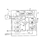
- FIG. 2 is a block diagram of the base station 10.
- a thick line between blocks indicates a power line
- a thin line indicates a communication signal line
- a broken line indicates a control signal line.
- the grid refers to a power distribution system of a power company
- the backhaul network refers to a communication infrastructure network constructed by a telecommunications carrier.
- the base station 10 includes a solar power generation device (hereinafter referred to as PV) 11, a battery 12, a communication unit 13, a power transmission unit 14, a measurement unit 15, and a storage unit 16. And a control unit 17.
- the battery 12, the communication unit 13, the power transmission unit 14, the measurement unit 15, the storage unit 16, and the control unit 17 are provided in the base station body (case body) 18.
- PV11 receives sunlight and generates power, and outputs the electric power obtained by power generation.
- the PV 11 is configured separately from the base station main body 18, but may be configured integrally with the base station main body 18.
- this embodiment mainly demonstrates the structure in which the base station 10 mounts PV11, the base station 10 does not necessarily need to mount PV11.
- the communication unit 13 includes a wireless communication unit 131 for performing wireless communication with the wireless terminal 20 and a network communication unit 132 for performing communication with the network side (EPC or other base station).
- a wireless communication unit 131 for performing wireless communication with the wireless terminal 20
- a network communication unit 132 for performing communication with the network side (EPC or other base station).
- the battery 12 stores the power generated by the PV 11 and the power from the system, and discharges the stored power under the control of the control unit 17.
- the battery 12 is, for example, a lithium type, but may be a recycle type used in an electric vehicle.
- the battery 12 may be a UPS (Uninterruptable Power Supply) system type that stores power from the grid.
- UPS Uninterruptable Power Supply
- the power transmission means 14 is a path (first path) 141 for transmitting power from the grid to each block of the base station 10 and a path (second path) for transmitting power from the battery 12. 142, a path (third path) 143 for transmitting power from the PV, and a switch (hereinafter referred to as SW) 144 for selectively switching each path.
- FIG. 2 a path for transmitting power from the SW 144 to the communication unit 13 is illustrated, but in actuality, each path for transmitting power from the SW 144 to other blocks (such as the control unit 17) is also illustrated. Provided.
- a detection unit 145 that detects a stop (power failure) of power supply from the system is provided.
- the existing technology can be used as a power failure detection method.
- the detection unit 145 notifies the control unit 17 to that effect.
- the measurement unit 15 measures the electric power stored in the battery 12 (hereinafter referred to as the remaining amount of storage) under the control of the control unit 17. When the measurement unit 15 measures the remaining amount of electricity stored, the measurement unit 15 outputs the measurement result to the storage unit.
- the storage unit 16 stores various information used for control by the control unit 17. In the present embodiment, the storage unit 16 stores information indicating the remaining amount of electricity stored by the measurement unit 15.
- the control unit 17 controls various functions of the base station 10.
- the control unit 17 includes a communication control unit 171 and a power control unit 172.
- the communication control unit 171 controls the communication unit 13. Specifically, the communication control unit 171 controls wireless communication with the wireless terminal 20 (communication by the wireless communication unit 131) and communication using the X2 interface and the S1 interface (communication by the network communication unit 132).
- the communication control unit 171 acquires information indicating the remaining amount of electricity stored in the battery 12 (hereinafter referred to as “remaining electricity remaining amount information”) from the storage unit 16, and uses the acquired remaining electricity storage information as a notification control channel that is a type of logical channel.
- the wireless communication unit 131 is controlled to transmit using (BCCH).
- the remaining power storage information may be a value (wattage (W)) of the remaining power stored in the battery 12, and an index (for example, Full is “11” indicating the degree of the remaining power stored in the battery 12. , Middle may be “10”, Low may be “01”, and Empty may be “00”).
- the communication control unit 171 transmits the remaining power storage information included in the system information block (SIB).
- SIB type 3 which is a type of SIB and mainly includes parameters related to celery selection
- the Battery Status IE that is an information element (IE) corresponding to the remaining power storage information.
- IE information element
- Each SIB3 IE other than the Battery Status IE can be the same as the existing SIB3 specified in the 3GPP standard (for example, 3GPP TS36.331 V10.1.0 “6.3.1 System information blocks”) reference). Since SIB3 is transmitted regularly, Battery Status IE is also transmitted periodically.
- the power control unit 172 controls the SW 144 and the battery 12.
- the power control unit 172 controls the SW 144 to supply power from the battery 12 to each block.
- control is performed so that power is supplied not only from the battery 12 but also from the PV 11. In this case, with respect to the discharge control of the battery 12, it is desirable to control the battery 12 to cover the shortage of the power generated by the PV 11 based on the time zone and weather information.
- the power control unit 172 controls the measurement unit 15.
- the power control unit 172 controls the measurement unit 15 to start measuring the remaining amount of power stored in the battery 12. Measurement is performed periodically (for example, every 20 msec to several minutes). Note that the measurement of the remaining amount of electricity stored in the battery 12 may be started after a predetermined time has elapsed since the detection of the power failure. Then, the power control unit 172 performs control until the power supply from the system is restarted (the measurement is not stopped until the power supply is restarted).
- the power control unit 172 controls the storage unit 16.
- the power control unit 172 stores the measurement result of the remaining power amount in the storage unit 16.
- the power control unit 172 updates the remaining power storage information stored in the storage unit 16 every time measurement is performed.
- the remaining power amount information stored in the storage unit 16 is used by the communication control unit 171 as described above.
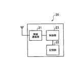
- FIG. 3 is a block diagram of the wireless terminal 20.
- the wireless terminal 20 includes a wireless communication unit 21, a storage unit 22, and a control unit 23.
- the wireless communication unit 21 is configured to perform wireless communication with the cell of the base station 10.
- the storage unit 22 stores various information used for control by the control unit 23.
- the control unit 23 controls various functions of the wireless terminal 20.
- the control unit 23 corresponds to a processor that executes programs stored in the storage unit 22 and performs various processes.
- control unit 23 controls the wireless communication unit 21 so as to receive SIB transmitted from the cell of each base station 10 on the BCCH.
- the SIB is configured to be able to identify the source cell.
- the control unit 23 performs wireless communication so as to measure the received power (RSRP) of a reference signal receivable from each cell based on each parameter related to celery selection included in each SIB (SIB3) received by the wireless communication unit 21.
- the unit 21 is controlled.
- the reference signal is configured to be able to identify the source cell.
- the control unit 23 performs celery selection based on each parameter related to celery selection and the received power measured by the wireless communication unit 21.
- the determination of celery selection is basically performed according to the celery selection procedure defined in the 3GPP standard (for example, refer to 3GPP TS36.304 V10.1.0 “5.2 Cell selection and selection”).
- the control unit 23 performs celery selection in consideration of the Battery Status IE.
- the selection priority of a cell (base station 10) with a large amount of remaining power indicated by the Battery Status IE is raised in the standard criteria for celery selection. Thereby, it is possible to preferentially select the base station 10 having a large amount of remaining power as a standby destination without selecting the base station 10 having a small amount of remaining power as a standby destination.
- a cell (base station 10) in which the remaining power level indicated by the Battery Status IE is below the threshold value may be excluded from the standby targets.
- only the cell (base station 10) in which the remaining amount of electricity indicated by the Battery Status IE exceeds the threshold is set as a standby candidate.
- the Battery Status IE is received multiple times from the same cell, the fluctuation state of the remaining power level indicated by each Battery Status IE is determined, and the remaining power level is a cell whose threshold value exceeds the threshold. Only a cell with a small amount fluctuation (that is, a stable remaining power amount) may be set as a standby candidate.
- control unit 23 When the control unit 23 selects a new standby cell in this manner, the control unit 23 controls the wireless communication unit 21 to perform standby for the new standby cell.
- control part 17 controls the radio
- the control unit 17 performs a connection process with respect to the standby cell. And control to shift from the idle state to the connected state.
- FIG. 4 is an operation sequence diagram of the mobile communication system 1 when a power failure is detected.
- the base stations 10-1 to 10-3 detect a power failure.
- step S2-1 to step S2-3, base station 10-1 to base station 10-3 measure the remaining power storage capacity of the own station.
- the base station 10-1 to base station 10-3 store the measured remaining power storage capacity of the own station.
- the base station 10-1 to the base station 10-3 include the Battery Status IE indicating the stored power storage remaining amount in the SIB3 and transmits it on the BCCH. .
- step S5-1 to step S5-3 the radio terminal 20 stores each SIB3 received from the base station 10-1 to the base station 10-3.
- step S6 the radio terminal 20 performs cell reselection according to the above-described cell reselection procedure based on each parameter related to cell reselection included in each SIB3 and the received power to be measured.
- the radio terminal 20 waits for a cell of the base station 10 having a large amount of stored power over a base station 10 having a small amount of stored power. It can be.
- the wireless terminal 20 in the idle state shifts to the connected state, the wireless terminal 20 connects to the base station 10 and communicates with the connected base station 10. For this reason, as a result of the load on the connection destination base station 10 increasing, the power consumption of the connection destination base station 10 increases.
- the load on the base station 10 with a small amount of remaining power increases (the power consumption increases). ) Can be prevented.
- compatibility with the existing specifications can be maintained by adding the IE of the remaining power amount information to the SIB defined by the 3GPP standard.
- the base station 10 when the base station 10 detects a power failure, the base station 10 starts to periodically transmit the remaining power storage information (Battery Status IE).
- Battery Status IE the remaining power storage information
- planned power outages rotary power outages
- planned power outages are performed sequentially for each region, and the time (period) during which a power outage occurs is grasped in advance. Is possible.
- the base station 10 periodically transmits the remaining power storage information (Battery Status IE) based on information related to the planned power outage (hereinafter referred to as planned power outage information) before the time when the power outage is scheduled. You may start.
- Battery Status IE Battery Status IE
- the power control unit 172 of the base station 10 acquires the planned power outage information received from the network side by the network communication unit 132, and the battery before the scheduled power outage start time based on the acquired planned power outage information. 12 measurement of the remaining amount of stored electricity is started, and periodic transmission of the remaining amount of stored electricity is started.
- the Battery Status IE is included in the SIB3 and transmitted, but may be included in the SIB other than the SIB3 or may be transmitted included in the control information other than the SIB.
- the Battery Status IE may be used for a handover process.
- each base station 10 may transmit the remaining power storage information on a daily basis. Good.
- the power control unit 172 of the base station 10 is in the midnight time zone where the price is lower than the power price in the day time zone.
- the battery 12 is charged with electric power, and for example, the base station 10 is controlled to be driven by the electric power stored in the battery 12 from 7:00 am.
- the power control unit 172 controls the base station 10 to appropriately consume the power generated by the PV 11.
- the power control unit 172 controls the base station 10 to be driven by power from the grid as an auxiliary.
- each base station 10 since the battery 12 is one of the main power sources, each base station 10 periodically transmits the remaining power amount information, so that the idle radio terminal 200 The remaining power amount information of each base station 10 can be grasped. For this reason, the wireless terminal 200 in the idle state can appropriately perform celery selection in consideration of the power situation.
- the communication control method, the base station, the wireless terminal, and the processor according to the present invention can enable mobility control in consideration of power circumstances in a mobile communication system that supports SON technology. This is useful in the field of wireless communication such as communication.
Landscapes
- Engineering & Computer Science (AREA)
- Computer Networks & Wireless Communication (AREA)
- Signal Processing (AREA)
- Mobile Radio Communication Systems (AREA)
- Telephone Function (AREA)
Abstract
Description
図1は、移動通信システム1の全体構成図である。本実施形態に係る移動通信システム1は、LTE Advanced(3GPPリリース10以降)に基づいて構成される。
次に、基地局10の構成を説明する。図2は、基地局10のブロック図である。図2において、各ブロック間における太線は電力ラインを示し、細線は通信信号ラインを示し、破線は制御信号ラインを示す。また、系統とは電力会社の配電系統を指し、バックホールネットワークとは通信事業者が構築する通信インフラネットワークを指す。
次に、無線端末20の構成を説明する。図3は、無線端末20のブロック図である。
次に、停電検出時における移動通信システム1の動作を説明する。図4は、停電検出時における移動通信システム1の動作シーケンス図である。
以上説明したように、実施形態によれば、無線端末20は、蓄電残量が少ない基地局10よりも蓄電残量が多い基地局10のセルを優先して待ち受け先とすることができる。
上記のように、本発明は実施形態によって記載したが、この開示の一部をなす論述及び図面はこの発明を限定するものであると理解すべきではない。この開示から当業者には様々な代替実施形態、実施例及び運用技術が明らかとなる。
Claims (10)
- バッテリーを備え、系統から供給される電力あるいは前記バッテリーから供給される電力によって駆動される基地局における通信制御方法において、
無線端末に対して、前記バッテリーの蓄電残量を示す情報を送信する送信ステップを含む、ことを特徴とする通信制御方法。 - 前記送信ステップは、前記バッテリーの蓄電残量を示す情報を定期的に送信する、ことを特徴とする請求項1に記載の通信制御方法。
- 前記送信ステップは、前記系統からの電力供給の停止に基づいて実行される、ことを特徴とする請求項1に記載の通信制御方法。
- 前記系統からの電力供給の停止を検出するステップを更に含み、
前記送信ステップは、前記系統からの電力供給の停止が検出されたときに、又は、前記系統からの電力供給の停止が検出されてから所定時間経過後に、前記バッテリーの蓄電残量を示す情報の送信を開始するステップを含む、ことを特徴とする請求項3に記載の通信制御方法。 - 前記系統からの電力供給が停止する予定時刻を示す情報を取得するステップを更に含み、
前記送信ステップは、前記系統からの電力供給が停止する予定時刻よりも所定時間前に、前記バッテリーの蓄電残量を示す情報の送信を開始するステップを含む、ことを特徴とする請求項3に記載の通信制御方法。 - 前記送信ステップは、前記バッテリーの蓄電残量を示す情報を、3GPP規格で規定されるSIB(System Information Block)に含めて送信する、ことを特徴とする請求項1に記載の通信制御方法。
- バッテリーを備え、系統から供給される電力あるいは前記バッテリーから供給される電力によって駆動される基地局との通信が可能な無線端末における通信制御方法において、
前記基地局から、前記バッテリーの蓄電残量を示す情報を受信するステップと、
前記バッテリーの蓄電残量を示す情報をセルリセレクションに使用するステップと、
を含むことを特徴とする通信制御方法。 - バッテリーを備え、系統から供給される電力あるいは前記バッテリーから供給される電力によって駆動される基地局において、
無線端末に対して、前記バッテリーの蓄電残量を示す情報を送信する送信部を含む、ことを特徴とする基地局。 - バッテリーを備え、系統から供給される電力あるいは前記バッテリーから供給される電力によって駆動される基地局との通信が可能な無線端末であって、
前記基地局から、前記バッテリーの蓄電残量を示す情報を受信する受信部を含み、
前記バッテリーの蓄電残量を示す情報をセルリセレクションに使用する、ことを特徴とする無線端末。 - 基地局との通信が可能な無線端末に備えられるプロセッサであって、
前記基地局は、バッテリーを備え、系統から供給される電力あるいは前記バッテリーから供給される電力によって駆動されるものであり、
前記プロセッサは、
前記無線端末が、前記基地局から前記バッテリーの蓄電残量を示す情報を受信するための処理と、
前記無線端末が、前記バッテリーの蓄電残量を示す情報をセルリセレクションに使用するための処理と、を行うように構成されている、ことを特徴とするプロセッサ。
Priority Applications (2)
| Application Number | Priority Date | Filing Date | Title |
|---|---|---|---|
| JP2013518039A JP5763760B2 (ja) | 2011-05-27 | 2012-05-24 | 通信制御方法、基地局、無線端末、及びプロセッサ |
| US14/122,190 US9402211B2 (en) | 2011-05-27 | 2012-05-24 | Communication control method, base station, radio terminal, and processor |
Applications Claiming Priority (2)
| Application Number | Priority Date | Filing Date | Title |
|---|---|---|---|
| JP2011-119768 | 2011-05-27 | ||
| JP2011119768 | 2011-05-27 |
Publications (1)
| Publication Number | Publication Date |
|---|---|
| WO2012165308A1 true WO2012165308A1 (ja) | 2012-12-06 |
Family
ID=47259165
Family Applications (1)
| Application Number | Title | Priority Date | Filing Date |
|---|---|---|---|
| PCT/JP2012/063392 Ceased WO2012165308A1 (ja) | 2011-05-27 | 2012-05-24 | 通信制御方法、基地局、無線端末、及びプロセッサ |
Country Status (3)
| Country | Link |
|---|---|
| US (1) | US9402211B2 (ja) |
| JP (1) | JP5763760B2 (ja) |
| WO (1) | WO2012165308A1 (ja) |
Cited By (3)
| Publication number | Priority date | Publication date | Assignee | Title |
|---|---|---|---|---|
| JP2015154335A (ja) * | 2014-02-17 | 2015-08-24 | 京セラ株式会社 | 通信装置、通信システムおよび通信制御方法 |
| WO2026004125A1 (ja) * | 2024-06-28 | 2026-01-02 | 株式会社Nttドコモ | ネットワークノード、基地局、端末、及び通信方法 |
| WO2026004126A1 (ja) * | 2024-06-28 | 2026-01-02 | 株式会社Nttドコモ | 基地局、端末、ネットワークノード、及び通信方法 |
Families Citing this family (3)
| Publication number | Priority date | Publication date | Assignee | Title |
|---|---|---|---|---|
| JP5833364B2 (ja) * | 2011-07-08 | 2015-12-16 | 京セラ株式会社 | 通信制御方法及び基地局 |
| US10728164B2 (en) * | 2016-02-12 | 2020-07-28 | Microsoft Technology Licensing, Llc | Power-aware network communication |
| JP2019041504A (ja) * | 2017-08-25 | 2019-03-14 | 富士通株式会社 | 電源制御回路、無線モジュールおよび信号発信器 |
Citations (5)
| Publication number | Priority date | Publication date | Assignee | Title |
|---|---|---|---|---|
| JP2002330095A (ja) * | 2001-04-26 | 2002-11-15 | Kyocera Corp | 基地局、基地局の制御方法及び移動通信システム |
| JP2003087840A (ja) * | 2001-09-10 | 2003-03-20 | Ntt Docomo Inc | セル形状制御方法及び移動通信システム並びにそのシステムで用いられる基地局及び移動機 |
| JP2005151288A (ja) * | 2003-11-18 | 2005-06-09 | Kddi Corp | 移動通信システム |
| JP2009005170A (ja) * | 2007-06-22 | 2009-01-08 | Canon Inc | 通信装置、制御方法及びプログラム |
| JP2011066593A (ja) * | 2009-09-16 | 2011-03-31 | Fujitsu Ltd | バッテリー動作可能無線基地局装置 |
Family Cites Families (6)
| Publication number | Priority date | Publication date | Assignee | Title |
|---|---|---|---|---|
| US4673826A (en) * | 1984-12-20 | 1987-06-16 | The United States Of America As Represented By The Secretary Of The Air Force | Autonomous uninterruptable power supply apparatus |
| US8228853B2 (en) * | 2008-02-01 | 2012-07-24 | Qualcomm Incorporated | Serving base station selection in a wireless communication network |
| JP4592781B2 (ja) * | 2008-04-24 | 2010-12-08 | 京セラ株式会社 | 基地局 |
| US8848658B2 (en) | 2009-04-17 | 2014-09-30 | Qualcomm Incorporated | Inter-frequency indication of association data for multi-carrier wireless deployments |
| JP2011061456A (ja) * | 2009-09-09 | 2011-03-24 | Sharp Corp | 通信システム、移動局装置および基地局装置 |
| US8554224B2 (en) * | 2010-03-24 | 2013-10-08 | Qualcomm Incorporated | Cellular network energy saving |
-
2012
- 2012-05-24 WO PCT/JP2012/063392 patent/WO2012165308A1/ja not_active Ceased
- 2012-05-24 US US14/122,190 patent/US9402211B2/en not_active Expired - Fee Related
- 2012-05-24 JP JP2013518039A patent/JP5763760B2/ja not_active Expired - Fee Related
Patent Citations (5)
| Publication number | Priority date | Publication date | Assignee | Title |
|---|---|---|---|---|
| JP2002330095A (ja) * | 2001-04-26 | 2002-11-15 | Kyocera Corp | 基地局、基地局の制御方法及び移動通信システム |
| JP2003087840A (ja) * | 2001-09-10 | 2003-03-20 | Ntt Docomo Inc | セル形状制御方法及び移動通信システム並びにそのシステムで用いられる基地局及び移動機 |
| JP2005151288A (ja) * | 2003-11-18 | 2005-06-09 | Kddi Corp | 移動通信システム |
| JP2009005170A (ja) * | 2007-06-22 | 2009-01-08 | Canon Inc | 通信装置、制御方法及びプログラム |
| JP2011066593A (ja) * | 2009-09-16 | 2011-03-31 | Fujitsu Ltd | バッテリー動作可能無線基地局装置 |
Cited By (3)
| Publication number | Priority date | Publication date | Assignee | Title |
|---|---|---|---|---|
| JP2015154335A (ja) * | 2014-02-17 | 2015-08-24 | 京セラ株式会社 | 通信装置、通信システムおよび通信制御方法 |
| WO2026004125A1 (ja) * | 2024-06-28 | 2026-01-02 | 株式会社Nttドコモ | ネットワークノード、基地局、端末、及び通信方法 |
| WO2026004126A1 (ja) * | 2024-06-28 | 2026-01-02 | 株式会社Nttドコモ | 基地局、端末、ネットワークノード、及び通信方法 |
Also Published As
| Publication number | Publication date |
|---|---|
| JP5763760B2 (ja) | 2015-08-12 |
| US20140087738A1 (en) | 2014-03-27 |
| US9402211B2 (en) | 2016-07-26 |
| JPWO2012165308A1 (ja) | 2015-02-23 |
Similar Documents
| Publication | Publication Date | Title |
|---|---|---|
| JP5759266B2 (ja) | 通信制御方法及び基地局 | |
| JP5833364B2 (ja) | 通信制御方法及び基地局 | |
| JP5763760B2 (ja) | 通信制御方法、基地局、無線端末、及びプロセッサ | |
| EP2731385B1 (en) | Control processing method of energy-saving cell and base station | |
| US8917668B1 (en) | System and method for energy saving in a wireless system | |
| US9084117B2 (en) | Dynamic mobility management in cell-breathing base stations in a cellular telecommunication network | |
| EP3070981B1 (en) | Energy saving method and device for heterogeneous network | |
| US20130150044A1 (en) | Method and base station for energy saving compensation | |
| US20130083714A1 (en) | Radio communication system, radio base station, and communication control method | |
| EP2708071A1 (en) | Saving energy in muliti - rat communication network | |
| EP3488633B1 (en) | Decentralized base station load balancing | |
| Matyokubov et al. | Increasing energy efficiency of base stations in mobile communication systems | |
| CN115039451B (zh) | 通信网络中的网络节点和在其中执行的方法 | |
| CN102572916B (zh) | 邻小区关系的测量方法和系统 | |
| US11277797B1 (en) | Disabling uplink leg switching of dual-connected device in response to low battery energy and high rate of uplink leg switching | |
| EP4518075A2 (en) | Virtual power plant configuration | |
| EP2747490A1 (en) | Session termination in an energy-efficient cellular wireless telecommunications system | |
| CN102300185B (zh) | 基于wimax实现邻区消息配置的方法和基站 | |
| JP2013021428A (ja) | 通信制御方法及び基地局 | |
| CN107078760A (zh) | 用于备份或备用发动机供电的无线电信网络的性能监控系统 |
Legal Events
| Date | Code | Title | Description |
|---|---|---|---|
| 121 | Ep: the epo has been informed by wipo that ep was designated in this application |
Ref document number: 12793694 Country of ref document: EP Kind code of ref document: A1 |
|
| ENP | Entry into the national phase |
Ref document number: 2013518039 Country of ref document: JP Kind code of ref document: A |
|
| WWE | Wipo information: entry into national phase |
Ref document number: 14122190 Country of ref document: US |
|
| NENP | Non-entry into the national phase |
Ref country code: DE |
|
| 122 | Ep: pct application non-entry in european phase |
Ref document number: 12793694 Country of ref document: EP Kind code of ref document: A1 |