WO2012165252A1 - 蓄電装置 - Google Patents
蓄電装置 Download PDFInfo
- Publication number
- WO2012165252A1 WO2012165252A1 PCT/JP2012/063158 JP2012063158W WO2012165252A1 WO 2012165252 A1 WO2012165252 A1 WO 2012165252A1 JP 2012063158 W JP2012063158 W JP 2012063158W WO 2012165252 A1 WO2012165252 A1 WO 2012165252A1
- Authority
- WO
- WIPO (PCT)
- Prior art keywords
- storage battery
- flow path
- battery modules
- cooling medium
- heating medium
- Prior art date
- Legal status (The legal status is an assumption and is not a legal conclusion. Google has not performed a legal analysis and makes no representation as to the accuracy of the status listed.)
- Ceased
Links
Images


Classifications
-
- H—ELECTRICITY
- H01—ELECTRIC ELEMENTS
- H01M—PROCESSES OR MEANS, e.g. BATTERIES, FOR THE DIRECT CONVERSION OF CHEMICAL ENERGY INTO ELECTRICAL ENERGY
- H01M10/00—Secondary cells; Manufacture thereof
- H01M10/60—Heating or cooling; Temperature control
- H01M10/65—Means for temperature control structurally associated with the cells
- H01M10/656—Means for temperature control structurally associated with the cells characterised by the type of heat-exchange fluid
-
- H—ELECTRICITY
- H01—ELECTRIC ELEMENTS
- H01M—PROCESSES OR MEANS, e.g. BATTERIES, FOR THE DIRECT CONVERSION OF CHEMICAL ENERGY INTO ELECTRICAL ENERGY
- H01M10/00—Secondary cells; Manufacture thereof
- H01M10/60—Heating or cooling; Temperature control
- H01M10/61—Types of temperature control
- H01M10/613—Cooling or keeping cold
-
- H—ELECTRICITY
- H01—ELECTRIC ELEMENTS
- H01M—PROCESSES OR MEANS, e.g. BATTERIES, FOR THE DIRECT CONVERSION OF CHEMICAL ENERGY INTO ELECTRICAL ENERGY
- H01M10/00—Secondary cells; Manufacture thereof
- H01M10/60—Heating or cooling; Temperature control
- H01M10/61—Types of temperature control
- H01M10/615—Heating or keeping warm
-
- Y—GENERAL TAGGING OF NEW TECHNOLOGICAL DEVELOPMENTS; GENERAL TAGGING OF CROSS-SECTIONAL TECHNOLOGIES SPANNING OVER SEVERAL SECTIONS OF THE IPC; TECHNICAL SUBJECTS COVERED BY FORMER USPC CROSS-REFERENCE ART COLLECTIONS [XRACs] AND DIGESTS
- Y02—TECHNOLOGIES OR APPLICATIONS FOR MITIGATION OR ADAPTATION AGAINST CLIMATE CHANGE
- Y02E—REDUCTION OF GREENHOUSE GAS [GHG] EMISSIONS, RELATED TO ENERGY GENERATION, TRANSMISSION OR DISTRIBUTION
- Y02E60/00—Enabling technologies; Technologies with a potential or indirect contribution to GHG emissions mitigation
- Y02E60/10—Energy storage using batteries
Definitions
- the present invention includes a storage battery module, a cooling medium flow path for circulating a cooling medium for cooling the storage battery module, and a heating medium flow path for circulating a heating medium for heating the storage battery module.
- the present invention relates to a power storage device.
- Patent Document 1 Conventionally, a power storage device mounted on an electric vehicle or the like and serving as a drive source is known.
- the power storage device described in Patent Document 1 is equipped with a temperature adjustment mechanism for maintaining the temperature of the storage battery of the power storage device in an appropriate range in consideration of the use of the power storage device in a low temperature environment or a high temperature environment. ing.
- a flow path for circulating a temperature adjusting medium which is called a heat pipe in Patent Document 1
- a temperature adjusting mechanism between storage batteries is arranged as a temperature adjusting mechanism between storage batteries.
- Patent Document 1 a flow path for circulating a temperature adjusting medium is used both as a cooling flow path and a heating flow path. For this reason, it takes time to switch from the cooling state to the heating state or from the heating state to the cooling state. Therefore, it is considered that the problem of switching time can be solved if separate channels are used for the cooling channel and the heating channel.
- the cooling flow path and the heating flow path are separate from each other, the cooling range and the heating range vary depending on the arrangement of the flow paths, and the storage battery There is a possibility that the temperature cannot be made uniform.
- An object of the present invention is to provide a power storage device that can suitably adjust the temperature of a storage battery module.
- a power storage device including a plurality of storage battery modules arranged along a predetermined arrangement direction.
- the power storage device further includes a cooling medium flow path for circulating a cooling medium for cooling the storage battery module, and a heating medium flow path for circulating a heating medium for heating the storage battery module.
- the cooling medium flow path and the heating medium flow path are alternately arranged in the arrangement direction of the storage battery module.
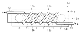
- FIG. 2 is a cross-sectional view taken along line 2-2 in FIG. The front view seen from the direction along the arrow 3 of FIG.
- the power storage device 10 includes a plurality of storage batteries connected in series, that is, a secondary battery, and a bar-shaped storage battery module 11 formed in a plurality of rows with a direction orthogonal to the axial direction of the storage battery module 11 as an arrangement direction. In 1, six rows are arranged.
- the power storage device 10 includes a cooling medium pipe 12 serving as a cooling medium flow path for circulating a cooling medium for cooling each storage battery module 11, and a heating medium for circulating a heating medium for heating each storage battery module 11. And a heating medium pipe 13 as a flow path.
- a liquid medium is used as both the cooling medium and the heating medium.
- the pair of metal support members 14 a and 14 b sandwich the plurality of storage battery modules 11 and are joined to each other to fix the plurality of storage battery modules 11. Accordingly, the plurality of storage battery modules 11 are arranged and arranged in a state where a predetermined interval is provided in the arrangement direction (left and right direction in FIG. 2). Terminal plates 15 a and 15 b are connected to both axial ends of each storage battery module 11. The terminal plates 15a and 15b are arranged at intervals from the support members 14a and 14b in the axial direction of the storage battery module 11 so as not to contact the support members 14a and 14b. As shown in FIG. 1, among the plurality of storage battery modules 11, temperature sensors S for detecting the temperature of the storage battery modules 11 are respectively provided on the outer peripheral surfaces of a predetermined number (three in the present embodiment) of storage battery modules 11. It is installed.
- the power storage device 10 according to the present embodiment will be described in detail, particularly focusing on the arrangement of the cooling medium pipe 12 and the heating medium pipe 13.
- the power storage device 10 includes one cooling medium pipe 12 and one heating medium pipe 13.
- Each of the cooling medium pipe 12 and the heating medium pipe 13 is disposed on each of the support members 14 a and 14 b so as to correspond between the storage battery modules 11. That is, each of the cooling medium pipe 12 and the heating medium pipe 13 has a plurality of first portions 12a and 13a extending along the axial direction (longitudinal direction) of the storage battery module 11, and the first portions 12a, The pipes 12 and 13 extend so as to meander with the storage battery module 11 in between by connecting the 13a with the second portions 12b and 13b.
- the first portion 12a of the cooling medium pipe 12 and the first portion 13a of the heating medium pipe 13 are alternately arranged in the arrangement direction of the storage battery module 11 in each of the support members 14a and 14b. That is, the first portion 12a of the cooling medium pipe 12 is disposed in each of the support members 14a and 14b with one gap between the storage battery modules 11 interposed therebetween. Similarly, the 1st part 13a of the heating medium pipe 13 is arrange
- the cooling medium pipe 12 is arranged around the storage battery module 11 so as to pass through the support member 14a and the support member 14b in this order.
- the cooling medium pipe 12 is configured such that the portions of the adjacent cooling medium pipes 12 in the support members 14 a and 14 b are shifted by twice the arrangement interval of the pair of adjacent storage battery modules 11 in the arrangement direction of the storage battery modules 11. Is arranged.
- the heating medium pipe 13 is disposed around the storage battery module 11 so as to pass through the support member 14a and the support member 14b in order.
- the heating medium pipes 13 are arranged so that the portions of the adjacent heating medium pipes 13 in the respective support members 14a and 14b are shifted by twice the arrangement interval of the pair of adjacent storage battery modules 11 in the arrangement direction. Has been.
- the first portion 12 a of the cooling medium pipe 12 is disposed between a pair of adjacent storage battery modules 11 in the arrangement direction of the storage battery modules 11. In this case, not the first portion 12a of the cooling medium pipe 12 but the first portion 13a of the heating medium pipe 13 is disposed on the second support member.
- the first portion 13a of the heating medium pipe 13 is between the pair of adjacent storage battery modules 11 in the arrangement direction of the storage battery modules 11. In the second support member, not the first portion 13a of the heating medium pipe 13 but the first portion 12a of the cooling medium pipe 12 is disposed on the second support member.
- the first part 12a of the cooling medium pipe 12 and the first part 13a of the heating medium pipe 13 are arranged such that different types of pipes are arranged between a pair of adjacent storage battery modules 11. It arrange
- the first portion 13a of the heating medium pipe 13 is disposed on the support member 14b.
- a heating medium is provided on the support member 14a.
- the first portion 13a of the pipe 13 is disposed, while the first portion 12a of the cooling medium pipe 12 is disposed on the support member 14b.
- the cooling medium pipe 12 and the heating medium pipe 13 have the same shape.
- the first portion 12 a of the cooling medium pipe 12 and the first portion 13 a of the heating medium pipe 13 are disposed between a pair of adjacent storage battery modules 11.
- the first portions 12a and 13a are arranged such that the distance from each storage battery module 11, that is, X and Y in the figure are the same. In the figure, X and Y are equal.
- the first portion 12a of the cooling medium pipe 12 and the first portion 13a of the heating medium pipe 13 have a predetermined interval in the arrangement direction of the storage battery module 11, that is, Z in the figure. It is arranged with a gap.
- the storage battery module 11 when the line segment which connects the center of each storage battery module 11 to an installation direction is used as a central axis, the storage battery module 11 is disposed between adjacent storage battery modules 11.
- the types of pipes arranged in a plane perpendicular to the direction are different, the positions of the pipes are symmetric with respect to the central axis.
- the first portion 12a of the cooling medium pipe 12 and the first portion 13a of the heating medium pipe 13 are arranged in a staggered manner across the row of the storage battery modules 11 along the arrangement direction of the storage battery modules 11. Yes.
- the first part 12 a of the cooling medium pipe 12 and the first part 13 a of the heating medium pipe 13 are arranged symmetrically across the row of the storage battery modules 11.
- the first portion 12a of the cooling medium pipe 12 and the first portion 13a of the heating medium pipe 13 are inserted through pipe holes formed in the support members 14a and 14b.
- the cooling medium pipe 12 and the heating medium pipe 13 are folded back outside the terminal plates 15a and 15b in the axial direction of the storage battery module 11, so that one of the supporting members 14a and 14b is supported by one of the supporting members 14a and 14b. Is inserted into the other side.
- the heating medium pipe 13 passes through the support member 14 b and is folded back outside the terminal plate 15 a in the axial direction of the storage battery module 11 and inserted into the support member 14 a.
- it is folded back from the terminal plate 15b in the axial direction of the storage battery module 11 from the support member 14a and inserted into the support member 14b.
- the power storage device 10 of this embodiment When the power storage device 10 of this embodiment is mounted on a vehicle such as an electric vehicle, the power storage device 10 is accommodated in a case body C indicated by a two-dot chain line in FIG.
- the vehicle is equipped with a cooling medium generation mechanism that generates a cooling medium and a heating medium generation mechanism that generates a heating medium.
- the cooling medium pipe 12 At the time of mounting, the cooling medium pipe 12 is connected to the cooling medium generation mechanism, and the heating medium pipe 13 is connected to the heating medium generation mechanism.
- Each temperature sensor S is connected to a control controller of the vehicle and outputs temperature information of the corresponding storage battery module 11 to the control controller.
- the controller determines that the storage battery module 11 needs to be cooled based on the temperature information
- the controller supplies the cooling medium pipe 12 to the cooling medium pipe 12 via the cooling medium generation mechanism.
- the controller determines that it is necessary to heat the storage battery module 11 based on the temperature information
- the controller supplies the heating medium to the heating medium pipe 13 via the heating medium generation mechanism.
- the case where the storage battery module 11 needs to be cooled is mainly when the storage battery is used, and the case where the storage battery module 11 needs to be heated is mainly when the vehicle is started.
- a plurality of power storage devices 10 are mounted on the vehicle.
- the cooling medium flows through the cooling medium pipe 12 when the storage battery module 11 is cooled, and the heating medium flows through the heating medium pipe 13 when the storage battery module 11 is heated. That is, in the power storage device 10, the cooling medium flow path and the heating medium flow path are respectively disposed as dedicated flow paths, that is, independent flow paths. For this reason, it is possible to efficiently switch between the circulation of the cooling medium and the circulation of the heating medium.
- the cooling medium circulates through the first portions 12a of the cooling medium pipes 12 disposed between the storage battery modules 11, respectively, thereby cooling each storage battery module 11.
- the heating medium circulates through the first portions 13a of the heating medium pipes 13 disposed between the storage battery modules 11, whereby each storage battery module 11 is heated. Is done.
- the first portions 12a of the cooling medium pipe 12 and the first portions 13a of the heating medium pipe 13 are alternately arranged in the arrangement direction in the support members 14a and 14b. Since it is arranged, it is possible to make the temperature of the storage battery module 11 uniform both during cooling and during heating. For example, in FIG.
- the first and second storage battery modules 11 from the left are cooled by the cooling medium flowing through the first portion 12a of the cooling medium pipe 12 arranged on the support member 14a during cooling.
- the heating medium is heated by the heating medium flowing through the first portion 13a of the heating medium pipe 13 disposed on the support member 14b.
- the cooling medium pipe 12 and the heating medium pipe 13 are used as dedicated flow paths, the cooling medium pipe 12 is circulated through the cooling medium pipe 12 when the storage battery module 11 is cooled, while the storage battery module 11 is heated when heated.
- a heating medium can be circulated through the heating medium pipe 13. That is, when both flow paths are used as dual-purpose flow paths, it takes time to switch the medium to be circulated through the flow paths. It is sufficient to distribute the medium, and the time efficiency can be improved. As a result, the temperature of the storage battery module 11 can be suitably adjusted.
- the first portion 12a of the cooling medium pipe 12 and the first portion 13a of the heating medium pipe 13 are also arranged in a direction orthogonal to the arrangement direction of the storage battery module 11. That is, the first portion 12a of the cooling medium pipe 12 and the first portion 13a of the heating medium pipe 13 are opposed to each other across the row of the storage battery modules 11 in a direction orthogonal to the direction in which the storage battery modules 11 are arranged. Are arranged to be. Thereby, the area
- the cooling action is achieved by alternately arranging the first portions 12a of the cooling medium pipe 12 and the first portions 13a of the heating medium pipe 13. And a heating effect can be uniformly given to each storage battery module 11.
- a pair of flow paths corresponding to a gap between a pair of adjacent storage battery modules 11 and spaced apart in a direction orthogonal to the direction in which the storage battery modules 11 are arranged distribute different types of media. It is a flow path to be made. For this reason, arrangement
- the first portion 12a of the cooling medium pipe 12 is disposed on the support member 14a and the heating medium pipe 13 is arranged.
- the first portion 13a is disposed on the support member 14b.
- the cooling medium flowing through the cooling medium pipe 12 gives a cooling action to the storage battery module 11, while the heating medium flowing through the heating medium pipe 13 gives a heating action to the storage battery module 11 during heating.
- the cooling medium flowing through the cooling medium pipe 12 gives a cooling action to the storage battery module 11
- the heating medium flowing through the heating medium pipe 13 gives a heating action to the storage battery module 11 during heating.
- the first portion 12a of the cooling medium pipe 12 and the first portion 13a of the heating medium pipe 13 are arranged between a pair of adjacent storage battery modules 11 so as to circulate through one flow path.
- a cooling action and a heating action can be given to a plurality of storage battery modules 11 by a medium (a cooling medium or a heating medium). Therefore, the flow path configuration can be simplified.
- the power storage device 10 of this embodiment When the power storage device 10 of this embodiment is mounted on a vehicle such as an electric vehicle, the power storage device 10 has the advantages (1) to (7) described above, thereby extending the life of the storage battery module 11. Reduction of running cost and improvement of the acceleration performance and maximum speed performance of the vehicle accompanying the increase in output of the storage battery module 11 can be realized.
- At least one of the first portion 12a of the cooling medium pipe 12 and the first portion 13a of the heating medium pipe 13 is arranged not correspondingly between the storage battery modules 11 but corresponding to one storage battery module 11. May be. According to this, for example, in FIG. 2, the number of flow paths arranged in the support members 14 a and 14 b increases from 5 to 6, but the cooling action and heating action by each flow path are one storage battery module 11. To focus on.
- a flow path may also be arranged outside the storage battery module 11 arranged at both ends of the storage battery module 10 in the arrangement direction of the storage battery module 11.
- the flow path arranged between a pair of adjacent storage battery modules 11 may be a flow path for distributing the same type of medium.
- the first portion 12 a of the pair of cooling medium pipes 12 (or the first of the heating medium pipes 13 is provided between the first and second storage battery modules 11 from the left. Only part 13a) may be arranged.
- the flow path is also disposed outside the storage battery module 11 that is disposed at both ends of the storage battery module 11 in the direction in which the storage battery module 11 is disposed.
- the cooling medium pipe 12 and the heating medium pipe 13 may be made independent in the arrangement of each flow path. Furthermore, the cooling medium pipe 12 and the heating medium pipe 13 arranged on the support member 14a are each used as one flow path, and the cooling medium pipe 12 and the heating medium pipe 13 arranged on the support member 14b are each one. It is good also as a flow path. That is, a separate cooling medium pipe 12 may be disposed on the support members 14a and 14b, and similarly, a separate heating medium pipe 13 may be disposed on the support members 14a and 14b.
- Both the cooling medium and the heating medium may be a gaseous medium. Further, one of the cooling medium and the heating medium may be a liquid medium, and the other may be a gaseous medium.
- the shape and number of flow paths arranged on the support members 14a and 14b may be different. You may arrange
- the storage battery module 11 may include only one storage battery.
- the storage battery constituting the storage battery module 11 may be either a cylindrical battery or a square battery.
- the support members 14a and 14b may be made of resin instead of metal. When the resin support member is used, a space may be provided between the support member and the terminal plates 15a and 15b, or the support member and the terminal plates 15a and 15b may be in contact with each other.
- the temperature sensor S may be attached to all the storage battery modules 11. Further, when power storage device 10 is mounted on a vehicle, instead of control based on temperature information output from temperature sensor S, heating is uniquely performed when the vehicle is started, and cooling is performed after a predetermined time has elapsed. It may be. Further, when the power storage device 10 is mounted on a vehicle, the storage battery module 11 may be cooled or heated based on the outside air temperature instead of the temperature information output from the temperature sensor S.
- the power storage device 10 When the power storage device 10 is housed in the case body C, the power storage device 10 may be fixed to the case body C with a fastener such as a bolt, or may be fixed to the case body C by resin filling.
- a fastener such as a bolt
Landscapes
- Engineering & Computer Science (AREA)
- Manufacturing & Machinery (AREA)
- Chemical & Material Sciences (AREA)
- Chemical Kinetics & Catalysis (AREA)
- Electrochemistry (AREA)
- General Chemical & Material Sciences (AREA)
- Secondary Cells (AREA)
- Battery Mounting, Suspending (AREA)
Abstract
蓄電装置は、所定の配設方向に沿って配置した複数の蓄電池モジュールを備える。該蓄電装置は、該蓄電池モジュールを冷却するための冷却媒体を流通させる冷却媒体流路と、該蓄電池モジュールを加温するための加温媒体を流通させる加温媒体流路と、をさらに備える。該冷却媒体流路及び該加温媒体流路は、該蓄電池モジュールの配設方向に交互に配置されている。
Description
本発明は、蓄電池モジュールと、該蓄電池モジュールを冷却するための冷却媒体を流通させる冷却媒体流路と、該蓄電池モジュールを加温するための加温媒体を流通させる加温媒体流路と、を有する蓄電装置に関する。
従来では、電気自動車などに搭載されて駆動源となる蓄電装置が知られている。特許文献1に記載の蓄電装置には、蓄電装置が低温環境下や高温環境下で使用されることを考慮し、蓄電装置の蓄電池の温度を適正範囲に維持するための温度調節機構が装備されている。特許文献1では、蓄電池同士の間には、特許文献1においてヒートパイプと呼ばれているところの、温度調節用の媒体を流通させる流路が温度調節機構として配置されている。
特許文献1では、温度調節用の媒体を流通させる流路が、冷却用の流路と加温用の流路とに兼用されている。このため、冷却状態から加温状態、又は加温状態から冷却状態への切換えに時間を要してしまう。そこで、冷却用の流路と加温用の流路とを別としてそれぞれ専用流路とすれば、切換え時間の問題は解消されると考えられる。しかしながら、冷却用の流路と加温用の流路とを別としてそれぞれ専用流路とした場合には、それらの流路の配置次第で冷却範囲と加温範囲とにムラが生じ、蓄電池の温度の均一化が図れない虞がある。
本発明の目的は、蓄電池モジュールの温度調節を好適に行うことができる蓄電装置を提供することにある。
上記目的を達成するため、本発明の一態様では、所定の配設方向に沿って配置した複数の蓄電池モジュールを備える蓄電装置を提供する。該蓄電装置は、前記蓄電池モジュールを冷却するための冷却媒体を流通させる冷却媒体流路と、前記蓄電池モジュールを加温するための加温媒体を流通させる加温媒体流路と、をさらに備える。前記冷却媒体流路及び前記加温媒体流路は、前記蓄電池モジュールの配設方向に交互に配置されている。
以下、本発明を具体化した一実施形態を図1~図3にしたがって説明する。
蓄電装置10には、直列に接続された複数の蓄電池、すなわち二次電池、から形成される棒状の蓄電池モジュール11が、蓄電池モジュール11の軸方向と直交する方向を配設方向として複数列、図1では6列、配置されている。蓄電装置10は、各蓄電池モジュール11を冷却するための冷却媒体を流通させる冷却媒体流路としての冷却媒体パイプ12と、各蓄電池モジュール11を加温するための加温媒体を流通させる加温媒体流路としての加温媒体パイプ13とを備える。本実施形態では、冷却媒体及び加温媒体として、何れも液体状の媒体が用いられている。
図2に示すように、金属製の一対の支持部材14a,14bは複数の蓄電池モジュール11を挟持するとともに、該複数の蓄電池モジュール11を固定するべく互いに接合されている。これにより、複数の蓄電池モジュール11は、配設方向(図2において左右方向)に所定の間隔をあけた状態で、整列配置される。各蓄電池モジュール11の軸方向両端には、端子板15a,15bが接続されている。端子板15a,15bは、支持部材14a,14bに接触しないように蓄電池モジュール11の軸方向に支持部材14a,14bから間隔をあけて配置されている。図1に示すように、複数の蓄電池モジュール11のうち、所定数(本実施形態では3つ)の蓄電池モジュール11の外周面には、蓄電池モジュール11の温度を検出するための温度センサSがそれぞれ装着されている。
以下、本実施形態の蓄電装置10について、特に冷却媒体パイプ12および加温媒体パイプ13の配置を中心に詳しく説明する。
図2に示すように、蓄電装置10は、1本の冷却媒体パイプ12と1本の加温媒体パイプ13とを備える。冷却媒体パイプ12及び加温媒体パイプ13の各々は、蓄電池モジュール11同士の間に対応するように、各支持部材14a,14bに配置されている。すなわち、冷却媒体パイプ12及び加温媒体パイプ13の各々は、蓄電池モジュール11の軸方向(長手方向)に沿って延びる複数の第1の部分12a,13aを有し、それら第1の部分12a,13aが第2の部分12b,13bによって連結されることにより、各パイプ12,13は蓄電池モジュール11を挟んで蛇行するように延びている。冷却媒体パイプ12の第1の部分12aと加温媒体パイプ13の第1の部分13aとは、各支持部材14a,14bにおいて、蓄電池モジュール11の配設方向に交互に配置されている。つまり、冷却媒体パイプ12の第1の部分12aは、各支持部材14a,14bにおいて、蓄電池モジュール11同士の間の間隙1つを挟んで配置されている。同様に、加温媒体パイプ13の第1の部分13aは、各支持部材14a,14bにおいて、蓄電池モジュール11同士の間の間隙1つを挟んで配置されている。
冷却媒体パイプ12は、支持部材14a及び支持部材14bを順に通るように蓄電池モジュール11の周辺に配置されている。冷却媒体パイプ12は、各支持部材14a,14bにおける隣接する冷却媒体パイプ12の部分同士が、蓄電池モジュール11の配設方向において、隣り合う一対の蓄電池モジュール11の配列間隔の2倍ずつずれるように配置されている。同様に、加温媒体パイプ13は、支持部材14a及び支持部材14bを順に通るように蓄電池モジュール11の周辺に配置されている。加温媒体パイプ13は、各支持部材14a,14bにおける隣接する加温媒体パイプ13の部分同士が、前記配設方向において、隣り合う一対の蓄電池モジュール11の配列間隔の2倍ずつずれるように配置されている。すなわち、支持部材14a,14bのうちの第1の支持部材について、冷却媒体パイプ12の第1の部分12aが、蓄電池モジュール11の配設方向において、隣り合う一対の蓄電池モジュール11同士の間に配置されている場合、第2の支持部材には冷却媒体パイプ12の第1の部分12aではなく加温媒体パイプ13の第1の部分13aが配置される。同様に、支持部材14a,14bのうちの第1の支持部材について、加温媒体パイプ13の第1の部分13aが、蓄電池モジュール11の配設方向において、隣り合う一対の蓄電池モジュール11同士の間に配置されている場合、第2の支持部材には加温媒体パイプ13の第1の部分13aではなく冷却媒体パイプ12の第1の部分12aが配置される。これにより、冷却媒体パイプ12の第1の部分12aと加温媒体パイプ13の第1の部分13aとは、隣り合う一対の蓄電池モジュール11同士の間に異なる種類のパイプが配置されるように、支持部材14a,14bに配置される。例えば、図2において、前記配設方向において最左方の一対の蓄電池モジュール11、すなわち、左から第1番目及び第2番目の蓄電池モジュール11については、冷却媒体パイプ12の第1の部分12aと加温媒体パイプ13の第1の部分13aとが該一対の蓄電池モジュール11同士の間に配置されるとともに、冷却媒体パイプ12の第1の部分12aが支持部材14aに配置されている一方で、加温媒体パイプ13の第1の部分13aが支持部材14bに配置されている。また、図2において、最左方の一対の蓄電池モジュール11の右隣の一対の蓄電池モジュール11、すなわち、左から第2番目及び第3番目の蓄電池モジュール11については、支持部材14aに加温媒体パイプ13の第1の部分13aが配置されている一方で、支持部材14bに冷却媒体パイプ12の第1の部分12aが配置されている。
本実施形態において冷却媒体パイプ12と加温媒体パイプ13とは、同一形状とされている。図2に示すように、冷却媒体パイプ12の第1の部分12aと加温媒体パイプ13の第1の部分13aとは、隣り合う一対の蓄電池モジュール11同士の間に配置されている。第1の部分12a,13aは、各蓄電池モジュール11からの離間距離、すなわち図中のX、Y、が同一であるように配置されている。なお、図中のX及びYは等しい。図2に示すように、冷却媒体パイプ12の第1の部分12aと加温媒体パイプ13の第1の部分13aとは、蓄電池モジュール11の配設方向において所定の間隔、すなわち図中のZをあけて配置されている。これにより、本実施形態の蓄電装置10では、各蓄電池モジュール11の中心を配設方向に結ぶ線分を中心軸線とした場合に、隣り合う蓄電池モジュール11同士の間を通り蓄電池モジュール11の配設方向に垂直な平面に配置されるパイプの種類は異なるが、パイプの位置は前記中心軸線について対称である。冷却媒体パイプ12の第1の部分12aおよび加温媒体パイプ13の第1の部分13aは、蓄電池モジュール11の配設方向に沿って同蓄電池モジュール11の列を挟んでそれぞれ千鳥状に配列されている。冷却媒体パイプ12の第1の部分12aと加温媒体パイプ13の第1の部分13aとは、蓄電池モジュール11の列を挟んで対称に配置されている。
冷却媒体パイプ12の第1の部分12aと加温媒体パイプ13の第1の部分13aとは、各支持部材14a,14bに形成されたパイプ孔に挿通されている。冷却媒体パイプ12と加温媒体パイプ13とは、蓄電池モジュール11の軸方向において端子板15a,15bより外側で折り返されることにより、支持部材14a,14bのうちの一方から支持部材14a,14bのうちの他方へ挿通されている。例えば、図3に示すように、加温媒体パイプ13は、その上流側から見ると、支持部材14bを通って蓄電池モジュール11の軸方向において端子板15aより外側で折り返されて支持部材14aに挿通されるとともに、支持部材14aから蓄電池モジュール11の軸方向において端子板15bより外側で折り返されて支持部材14bに挿通されている。
本実施形態の蓄電装置10は、電気自動車などの車両に搭載される場合、図1に二点鎖線によって示すケース体Cに収容される。該車両には、冷却媒体を生成する冷却媒体生成機構と、加温媒体を生成する加温媒体生成機構とが装備されている。搭載時、冷却媒体パイプ12は該冷却媒体生成機構に接続されるとともに、加温媒体パイプ13は該加温媒体生成機構に接続される。前記各温度センサSは車両の制御コントローラに接続されるとともに、当該制御コントローラに対して対応する蓄電池モジュール11の温度情報を出力する。制御コントローラは、該温度情報に基づき蓄電池モジュール11を冷却する必要があると判断すると、冷却媒体生成機構を介して冷却媒体パイプ12に冷却媒体を供給する。また、制御コントローラは、前記温度情報に基づき蓄電池モジュール11を加温する必要があると判断すると、加温媒体生成機構を介して加温媒体パイプ13に加温媒体を供給する。なお、蓄電池モジュール11を冷却する必要がある場合とは主に蓄電池の使用時であり、蓄電池モジュール11を加温する必要がある場合とは主に車両始動時である。蓄電装置10は、車両に複数個搭載される。
次に、本実施形態の蓄電装置10の作用を説明する。
本実施形態の蓄電装置10では、蓄電池モジュール11の冷却時に冷却媒体が冷却媒体パイプ12を流通するとともに、蓄電池モジュール11の加温時に加温媒体が加温媒体パイプ13を流通する。すなわち、蓄電装置10においては、冷却媒体の流路と加温媒体の流路とがそれぞれ専用流路、すなわち独立流路、として配置されている。このため、冷却媒体の流通と加温媒体の流通とを効率的に切換えることが可能となる。
蓄電池モジュール11の冷却時には、蓄電池モジュール11同士の間にそれぞれ配置されている冷却媒体パイプ12の第1の部分12aを冷却媒体が流通し、これによって各蓄電池モジュール11が冷却される。一方、蓄電池モジュール11の加温時には、蓄電池モジュール11同士の間にそれぞれ配置されている加温媒体パイプ13の第1の部分13aを加温媒体が流通し、これによって各蓄電池モジュール11が加温される。このとき、本実施形態の蓄電装置10では、各支持部材14a,14bにおいて冷却媒体パイプ12の第1の部分12aと加温媒体パイプ13の第1の部分13aとが前記配設方向に交互に配置されているから、冷却時及び加温時の何れでも蓄電池モジュール11の温度の均一化を図ることが可能となる。例えば、図2において、左から第1番目及び第2番目の蓄電池モジュール11は、冷却時において支持部材14aに配置されている冷却媒体パイプ12の第1の部分12aを流通する冷却媒体によって冷却されるとともに、加温時において支持部材14bに配置されている加温媒体パイプ13の第1の部分13aを流通する加温媒体によって加温される。
したがって、本実施形態によれば、以下に示す利点を得ることができる。
(1)冷却媒体パイプ12と加温媒体パイプ13とを専用流路とすることにより、蓄電池モジュール11の冷却時には冷却媒体パイプ12に冷却媒体を流通させる一方で、蓄電池モジュール11の加温時には加温媒体パイプ13に加温媒体を流通させることができる。すなわち、両流路を兼用流路とした場合には当該流路に流通させる媒体を切り換えるために時間を要するが、本実施形態のように専用流路とすれば必要時に適正な流路に対して媒体を流通させればよく、時間効率を向上させることができる。その結果、蓄電池モジュール11の温度調節を好適に行うことができる。
(2)兼用流路の場合には、加温から冷却又は冷却から加温への切り換えに際して、切り換え前に流通させていた媒体の影響を受けることになる。具体的に言えば、加温から冷却に切り換える場合、その流路は加温媒体によって温められた状態とされているので、冷却媒体を流通させても直ちにその冷却効果を発揮し難い。しかし、本実施形態のように専用流路とした場合には、その流路に対して同じ種類の媒体しか流通しないので、切り換え前に流通していた媒体の影響を低減できる。したがって、蓄電池モジュール11の温度調節を好適に行うことができる。
(3)冷却媒体パイプ12の第1の部分12aと加温媒体パイプ13の第1の部分13aとを蓄電池モジュール11の配設方向に交互に配置することにより、冷却媒体による冷却作用、及び加温媒体による加温作用を、各蓄電池モジュール11に対して均一に付与することができる。したがって、各蓄電池モジュール11の温度の均一化を図ることができる。その結果、蓄電池モジュール11の温度調節を好適に行うことができる。
(4)冷却媒体パイプ12の第1の部分12aと加温媒体パイプ13の第1の部分13aとを、蓄電池モジュール11の配設方向に直交する方向にも配置している。すなわち、冷却媒体パイプ12の第1の部分12aと加温媒体パイプ13の第1の部分13aとは、蓄電池モジュール11の配設方向に直交する方向において、蓄電池モジュール11の列を挟んで互いに対向するように配置されている。これにより、各蓄電池モジュール11に対して冷却作用及び加温作用を付与する領域を増加させることができ、温度調節をより好適に行うことができる。
(5)蓄電池モジュール11の配設方向に直交する方向においても、冷却媒体パイプ12の第1の部分12aと加温媒体パイプ13の第1の部分13aとを交互に配置することで、冷却作用及び加温作用を、各蓄電池モジュール11に対して均一に付与することができる。
(6)隣り合う一対の蓄電池モジュール11同士の間の間隙に対応し、蓄電池モジュール11の配設方向に直交する方向に離間して配置される一対の流路は、互いに異なる種類の媒体を流通させる流路である。このため、流路の配置を簡素化できる。具体的に言えば、図2において、左から第1番目及び第2番目の蓄電池モジュール11については、冷却媒体パイプ12の第1の部分12aを支持部材14aに配置するとともに、加温媒体パイプ13の第1の部分13aを支持部材14bに配置する。冷却時、冷却媒体パイプ12を流通する冷却媒体は蓄電池モジュール11に冷却作用を付与する一方で、加温時、加温媒体パイプ13を流通する加温媒体は蓄電池モジュール11に加温作用を付与することができる。つまり、蓄電装置10における蓄電池モジュール11の配設方向の両端に配置される蓄電池モジュール11には、その配設方向外側に冷却媒体又は加温媒体を流通させる流路が存在していなくても、異なる種類の媒体が流通する前記一対の流路によって冷却作用又は加温作用を付与することができる。
(7)冷却媒体パイプ12の第1の部分12aと加温媒体パイプ13の第1の部分13aとを隣り合う一対の蓄電池モジュール11同士の間に配置することで、1つの流路を流通する媒体(冷却媒体又は加温媒体)によって複数の蓄電池モジュール11を対象に冷却作用及び加温作用を付与することができる。したがって、流路構成を簡素化できる。
(8)本実施形態の蓄電装置10を電気自動車などの車両に搭載した場合には、蓄電装置10が上記(1)~(7)の利点を奏することにより、蓄電池モジュール11の長寿命化によるランニングコストの削減や、蓄電池モジュール11の出力増加に伴う車両の加速性能や最高速性能の向上を実現できる。
なお、上記実施形態は以下のように変更してもよい。
○ 冷却媒体パイプ12の第1の部分12a及び加温媒体パイプ13の第1の部分13aのうちの少なくとも一方を、蓄電池モジュール11同士の間ではなく、1つの蓄電池モジュール11に対応させて配置してもよい。これによれば、例えば、図2においては支持部材14a,14bに配置する流路の本数が5本から6本に増加するが、各流路による冷却作用や加温作用は1つの蓄電池モジュール11に集中することになる。
○ 蓄電装置10における蓄電池モジュール11の配設方向の両端に配置される蓄電池モジュール11の外側にも流路を配置してもよい。
○ 隣り合う一対の蓄電池モジュール11同士の間に配置される流路は、同一の種類の媒体を流通させる流路としてもよい。具体的に言えば、図2において、左から第1番目及び第2番目の蓄電池モジュール11の間に、一対の冷却媒体パイプ12の第1の部分12a(又は加温媒体パイプ13の第1の部分13a)のみを配置してもよい。この場合、蓄電装置10における蓄電池モジュール11の配設方向の両端に配置される蓄電池モジュール11の外側にも流路を配置する。
○ 各流路の配置において、冷却媒体パイプ12や加温媒体パイプ13を独立させた構成としてもよい。さらにまた、支持部材14aに配置される冷却媒体パイプ12と加温媒体パイプ13をそれぞれ1本の流路とし、支持部材14bに配置される冷却媒体パイプ12と加温媒体パイプ13をそれぞれ1本の流路としてもよい。すなわち、支持部材14a,14bに別個の冷却媒体パイプ12が配置されてもよく、同様に、支持部材14a,14bに別個の加温媒体パイプ13が配置されてもよい。
○ 冷却媒体及び加温媒体は、何れも気体状の媒体としてもよい。また、冷却媒体及び加温媒体のうち、何れか一方の媒体を液体状の媒体とし、他方を気体状の媒体としてもよい。
○ 支持部材14a,14bに配置する流路の形状や本数を異ならせてもよい。支持部材14a,14bのうち、何れか一方の支持部材にのみ流路を配置してもよい。
○ 蓄電池モジュール11は、1本の蓄電池のみを備えてもよい。また、蓄電池モジュール11を構成する蓄電池は、円筒型電池及び角型電池の何れでもよい。
○ 支持部材14a,14bを金属製に代えて樹脂製としてもよい。樹脂製の支持部材とする場合は、その支持部材と端子板15a,15bとの間に間隔をあけてもよいし、支持部材と端子板15a,15bが接していてもよい。
○ 温度センサSを、全ての蓄電池モジュール11に装着してもよい。また、蓄電装置10を車両に搭載する場合において、温度センサSから出力される温度情報に基づく制御に代えて、車両始動時には一義的に加温が行なわれ、所定時間経過後に冷却が行なわれるようにしてもよい。また、蓄電装置10を車両に搭載する場合において、温度センサSから出力される温度情報に代えて、外気温に基づき蓄電池モジュール11の冷却又は加温を行うようにしてもよい。
○ 蓄電装置10をケース体Cに収容する場合、蓄電装置10はボルトなどの締結具によってケース体Cに固定してもよいし、樹脂充填によってケース体Cに固定してもよい。
Claims (7)
- 所定の配設方向に沿って配置した複数の蓄電池モジュールと、
前記蓄電池モジュールを冷却するための冷却媒体を流通させる冷却媒体流路と、
前記蓄電池モジュールを加温するための加温媒体を流通させる加温媒体流路と、を備え、
前記冷却媒体流路及び前記加温媒体流路は、前記蓄電池モジュールの配設方向に交互に配置されている蓄電装置。 - 前記冷却媒体流路と前記加温媒体流路とは、前記蓄電池モジュールの配設方向に直交する方向においても交互に配置されている請求項1に記載の蓄電装置。
- 前記冷却媒体流路と前記加温媒体流路とは、前記蓄電池モジュールの配設方向において、隣り合う一対の蓄電池モジュール同士の間に配置されている請求項1又は請求項2に記載の蓄電装置。
- 前記冷却媒体流路と前記加温媒体流路は、前記蓄電池モジュールの配設方向に直交する方向において、蓄電池モジュールの列を挟んで互いに対向するように配置されている請求項1~請求項3のうち何れか一項に記載の蓄電装置。
- 前記冷却媒体流路は、前記蓄電池モジュールの配設方向において、隣り合う一対の蓄電池モジュール同士の間に配置されているとともに、同隣り合う一対の蓄電池モジュールそれぞれからの離間距離が同一であるように配置されている請求項1~請求項4のうち何れか一項に記載の蓄電装置。
- 前記加温媒体流路は、前記蓄電池モジュールの配設方向において、隣り合う一対の蓄電池モジュール同士の間に配置されているとともに、同隣り合う一対の蓄電池モジュールそれぞれからの離間距離が同一であるように配置されている請求項1~請求項5のうち何れか一項に記載の蓄電装置。
- 前記冷却媒体流路は複数であって、前記蓄電池モジュールの配設方向に沿って同蓄電池モジュールの列を挟んで千鳥状に配列され、
前記加温媒体流路は複数であって、前記蓄電池モジュールの配設方向に沿って同蓄電池モジュールの列を挟んで千鳥状に配列され、
前記冷却媒体流路と前記加温媒体流路とは、蓄電池モジュールの列を挟んで対称に配置される、請求項1~請求項6のうち何れか一項に記載の蓄電装置。
Applications Claiming Priority (2)
| Application Number | Priority Date | Filing Date | Title |
|---|---|---|---|
| JP2011-125455 | 2011-06-03 | ||
| JP2011125455A JP5772244B2 (ja) | 2011-06-03 | 2011-06-03 | 蓄電装置 |
Publications (1)
| Publication Number | Publication Date |
|---|---|
| WO2012165252A1 true WO2012165252A1 (ja) | 2012-12-06 |
Family
ID=47259111
Family Applications (1)
| Application Number | Title | Priority Date | Filing Date |
|---|---|---|---|
| PCT/JP2012/063158 Ceased WO2012165252A1 (ja) | 2011-06-03 | 2012-05-23 | 蓄電装置 |
Country Status (2)
| Country | Link |
|---|---|
| JP (1) | JP5772244B2 (ja) |
| WO (1) | WO2012165252A1 (ja) |
Cited By (3)
| Publication number | Priority date | Publication date | Assignee | Title |
|---|---|---|---|---|
| CN111490313A (zh) * | 2020-06-28 | 2020-08-04 | 四川大学 | 用于动力电池组的逆流式冷却系统及动力电池组 |
| CN111780469A (zh) * | 2020-06-23 | 2020-10-16 | 浙江吉智新能源汽车科技有限公司 | 一种换电站冷却循环系统 |
| CN115458830A (zh) * | 2022-09-16 | 2022-12-09 | 东风汽车集团股份有限公司 | 一种液冷装置和电池包 |
Families Citing this family (2)
| Publication number | Priority date | Publication date | Assignee | Title |
|---|---|---|---|---|
| JP6515441B2 (ja) * | 2014-03-31 | 2019-05-22 | ダイキン工業株式会社 | 給湯システム |
| CN118541849A (zh) * | 2022-01-17 | 2024-08-23 | 松下知识产权经营株式会社 | 电源系统、加温控制方法以及加温控制程序 |
Citations (4)
| Publication number | Priority date | Publication date | Assignee | Title |
|---|---|---|---|---|
| JPH04230962A (ja) * | 1990-04-26 | 1992-08-19 | Abb Patent Gmbh | 高温蓄電池 |
| JP2003197277A (ja) * | 2001-12-25 | 2003-07-11 | Honda Motor Co Ltd | 蓄電装置および車両駆動装置 |
| JP2006093155A (ja) * | 2004-09-23 | 2006-04-06 | Samsung Sdi Co Ltd | 二次電池モジュールの温度制御システム |
| JP2010146777A (ja) * | 2008-12-17 | 2010-07-01 | Panasonic Ev Energy Co Ltd | 組電池 |
Family Cites Families (2)
| Publication number | Priority date | Publication date | Assignee | Title |
|---|---|---|---|---|
| EP1705743B1 (en) * | 2005-03-25 | 2007-09-26 | Samsung SDI Co., Ltd. | Battery module |
| JP2010192409A (ja) * | 2009-02-20 | 2010-09-02 | Toyota Motor Corp | 蓄電池収納庫 |
-
2011
- 2011-06-03 JP JP2011125455A patent/JP5772244B2/ja not_active Expired - Fee Related
-
2012
- 2012-05-23 WO PCT/JP2012/063158 patent/WO2012165252A1/ja not_active Ceased
Patent Citations (4)
| Publication number | Priority date | Publication date | Assignee | Title |
|---|---|---|---|---|
| JPH04230962A (ja) * | 1990-04-26 | 1992-08-19 | Abb Patent Gmbh | 高温蓄電池 |
| JP2003197277A (ja) * | 2001-12-25 | 2003-07-11 | Honda Motor Co Ltd | 蓄電装置および車両駆動装置 |
| JP2006093155A (ja) * | 2004-09-23 | 2006-04-06 | Samsung Sdi Co Ltd | 二次電池モジュールの温度制御システム |
| JP2010146777A (ja) * | 2008-12-17 | 2010-07-01 | Panasonic Ev Energy Co Ltd | 組電池 |
Cited By (4)
| Publication number | Priority date | Publication date | Assignee | Title |
|---|---|---|---|---|
| CN111780469A (zh) * | 2020-06-23 | 2020-10-16 | 浙江吉智新能源汽车科技有限公司 | 一种换电站冷却循环系统 |
| CN111490313A (zh) * | 2020-06-28 | 2020-08-04 | 四川大学 | 用于动力电池组的逆流式冷却系统及动力电池组 |
| CN111490313B (zh) * | 2020-06-28 | 2020-11-13 | 四川大学 | 用于动力电池组的逆流式冷却系统及动力电池组 |
| CN115458830A (zh) * | 2022-09-16 | 2022-12-09 | 东风汽车集团股份有限公司 | 一种液冷装置和电池包 |
Also Published As
| Publication number | Publication date |
|---|---|
| JP5772244B2 (ja) | 2015-09-02 |
| JP2012252911A (ja) | 2012-12-20 |
Similar Documents
| Publication | Publication Date | Title |
|---|---|---|
| JP6655062B2 (ja) | 車両内に設けられた電圧供給装置のためのエネルギー供給モジュール | |
| JP4415570B2 (ja) | 集合電池 | |
| KR101534913B1 (ko) | 열전소자를 구비한 배터리 팩 공냉장치와 이의 제어 방법 | |
| EP2086035B1 (en) | Battery module case | |
| US20160111762A1 (en) | Electrical storage apparatus | |
| US9511648B2 (en) | Vehicle heater | |
| JP6166356B2 (ja) | 電池モジュール | |
| KR20190044180A (ko) | 차량용 배터리 냉각 장치 | |
| JP2013051099A (ja) | バッテリ温調用モジュール | |
| JP7184724B2 (ja) | バッテリ冷却装置及びバッテリ冷却構造 | |
| JP5516166B2 (ja) | 車両用電源装置 | |
| KR102364202B1 (ko) | 냉각 성능을 향상시킨 전기자동차용 배터리팩 | |
| JP2008311130A (ja) | 電源装置及びその冷却方法 | |
| JP5772244B2 (ja) | 蓄電装置 | |
| JP2012190675A (ja) | バッテリー装置 | |
| JP2015106531A (ja) | バッテリセル固定装置 | |
| JP2004296217A (ja) | 電池パック | |
| JP2012214106A (ja) | 車両用空調システム | |
| US20130183564A1 (en) | Vehicle battery system with non-uniformly spaced cells | |
| JP2018060594A (ja) | 電池モジュール | |
| CN107371381B (zh) | 用于对电池单元进行调温的方法和装置以及车辆 | |
| KR20140084487A (ko) | 차량용 전지셀 모듈 어셈블리 | |
| JP5888166B2 (ja) | 電池モジュール及び車両 | |
| JP2015156347A (ja) | バッテリ温調装置 | |
| JP5699900B2 (ja) | 電池モジュール |
Legal Events
| Date | Code | Title | Description |
|---|---|---|---|
| 121 | Ep: the epo has been informed by wipo that ep was designated in this application |
Ref document number: 12793651 Country of ref document: EP Kind code of ref document: A1 |
|
| NENP | Non-entry into the national phase |
Ref country code: DE |
|
| 122 | Ep: pct application non-entry in european phase |
Ref document number: 12793651 Country of ref document: EP Kind code of ref document: A1 |