WO2012165090A1 - 電子体温計 - Google Patents
電子体温計 Download PDFInfo
- Publication number
- WO2012165090A1 WO2012165090A1 PCT/JP2012/061062 JP2012061062W WO2012165090A1 WO 2012165090 A1 WO2012165090 A1 WO 2012165090A1 JP 2012061062 W JP2012061062 W JP 2012061062W WO 2012165090 A1 WO2012165090 A1 WO 2012165090A1
- Authority
- WO
- WIPO (PCT)
- Prior art keywords
- cap body
- electronic thermometer
- case body
- temperature
- section
- Prior art date
- Legal status (The legal status is an assumption and is not a legal conclusion. Google has not performed a legal analysis and makes no representation as to the accuracy of the status listed.)
- Ceased
Links
Images





Classifications
-
- G—PHYSICS
- G01—MEASURING; TESTING
- G01K—MEASURING TEMPERATURE; MEASURING QUANTITY OF HEAT; THERMALLY-SENSITIVE ELEMENTS NOT OTHERWISE PROVIDED FOR
- G01K1/00—Details of thermometers not specially adapted for particular types of thermometer
- G01K1/16—Special arrangements for conducting heat from the object to the sensitive element
-
- G—PHYSICS
- G01—MEASURING; TESTING
- G01K—MEASURING TEMPERATURE; MEASURING QUANTITY OF HEAT; THERMALLY-SENSITIVE ELEMENTS NOT OTHERWISE PROVIDED FOR
- G01K13/00—Thermometers specially adapted for specific purposes
- G01K13/20—Clinical contact thermometers for use with humans or animals
Definitions
- the present invention relates to an electronic thermometer, and more particularly, to a predictive electronic thermometer capable of measuring body temperature in a short time.
- an actual measurement type and a prediction type are known as electronic thermometers that enable measurement of a body temperature by sandwiching a temperature measuring unit between measurement sites such as the armpit and sublingual.
- Predictive electronic thermometers with the exception of complicated and expensive heat flow thermometers, use a method that predicts and measures body temperature using a single thermosensitive element such as a thermistor. ing.
- a prediction-type electronic thermometer using a single temperature sensor performs arithmetic processing according to a predetermined algorithm using, for example, information on temperature rise in a temperature measuring unit detected within a very short time from the start of measurement.
- the actual body temperature is predicted and measured, which is superior to the actual measurement type electronic thermometer in that the time required for measurement is greatly shortened. For example, in recent years, those whose measurement time has been shortened to 30 seconds or less have been put into practical use.
- Patent Document 1 Japanese Patent Laid-Open No. 2000-111414 (Patent Document 1), by improving the shape and dimensions of a metal cap body constituting the temperature measuring unit, the measurement time is about 20 to 30 seconds. It is described that it can be shortened.
- an electronic thermometer is naturally required to be able to measure body temperature with high accuracy. That is, even when the measurement time is shortened in the predictive electronic thermometer, the measurement accuracy is not allowed to decrease.
- the outer shape of the temperature measuring unit is a flat shape.
- the outer shape of the temperature measuring part is a substantially cylindrical shape, and no consideration is given to the fact that this is a flat shape. For this reason, in the case of an electronic thermometer as disclosed in the publication, there is a possibility that the measurement site and the temperature measurement unit may not be stably in contact with each other during measurement, which causes a problem in terms of measurement accuracy. There is a concern.
- the measurement time can be shortened to about 20 to 30 seconds as described above, but there is a need for further reduction of the measurement time.
- an object of the present invention is to provide an electronic thermometer having a simple configuration capable of measuring body temperature with high accuracy and in a short time.
- Another object of the present invention is to provide an electronic thermometer having a simple configuration that can be easily assembled and can measure body temperature with high accuracy and in a short time.
- An electronic thermometer includes a housing having a hollow internal temperature measuring section with a closed end, a bottomed cylindrical metal cap body forming the temperature measuring section, and the temperature measuring section described above. And a temperature-sensitive element disposed in the hollow interior.
- the cap body includes a tubular portion, a bottom portion, a curved corner portion that is located between the tubular portion and the bottom portion and continues to the tubular portion, and is perpendicular to the axial direction of the cap body.
- the section has a flat outer shape with a substantially oval cross section.
- the major axis in the cross section of the cylindrical part is A
- the minor axis in the cross section of the cylindrical part is B
- the axial length of the cap body is C
- the major axis A and the minor axis B The axial length C satisfies the condition of 0.5 ⁇ B / A ⁇ 1.0
- the minor axis B and the axial length C satisfy the condition of 3 ⁇ B ⁇ C. ing.
- the short axis B preferably satisfies the condition of 3 mm ⁇ B ⁇ 4 mm.
- the temperature sensing element is fixed to the cylindrical portion located near the boundary between the curved corner portion and the cylindrical portion.
- the temperature sensing element is constituted by a chip type thermistor including a temperature sensing portion made of a ceramic material.
- the temperature sensing element is fixed to the cap body so that the temperature sensing portion is in contact with the inner peripheral surface of the cap body.
- the electronic thermometer according to the present invention further includes a display unit for displaying the measurement result.
- the temperature sensing element is fixed to the cap body in a portion located on the same surface side as the surface of the housing on the side where the display unit is provided.
- the casing except for the temperature measuring section includes a lead wire drawn out from the temperature sensing element and a connection wiring to which the lead wire is connected.
- the main body casing includes a main body casing including an accommodating space for accommodating the board, and the main body casing includes a first case body assembled with the printed wiring board, the first case body, It is preferable that the said cap body is connected and the 2nd case body by which the said lead wire is penetrated is included.
- the printed wiring board is The first case body and the second case body are preferably configured so that the connection electrode is exposed.
- the cap body is fixed by extrapolating the cylindrical portion on the cap body at the tip of the casing except for the temperature measuring section. It is preferable that a fixing portion is provided. In that case, it is preferable that an extended portion extending from the fixed portion toward the bottom side of the cap body is further provided at the tip of the fixed portion.
- the extending portion is not in contact with the cap body.
- the extending portion reaches the portion where the temperature sensing element is disposed along the axial direction of the cap body.
- the surface of the extending portion is preferably mirror-finished.
- thermometer In the electronic thermometer according to the present invention, it is preferable that minute irregularities are provided on the surface of the extending portion.
- the inner peripheral surface of the cap body is preferably mirror-finished.
- an electronic thermometer having a simple configuration capable of measuring body temperature with high accuracy and in a short time can be provided.
- an electronic thermometer having a simple configuration that can be easily assembled and can measure body temperature with high accuracy and in a short time can be obtained.
- FIG. 6B is a cross-sectional view taken along the line VIB-VIB shown in FIG.
- FIG. 6B is a cross-sectional view taken along the line VIC-VIC shown in FIG. 6A of the cap body of the electronic thermometer according to the first embodiment of the present invention. It is a figure which shows the assembly procedure of the electronic thermometer in Embodiment 1 of this invention. It is a perspective view which shows one state in the middle of the assembly of the electronic thermometer in Embodiment 1 of this invention. It is a principal part expansion disassembled perspective view of the electronic thermometer in Embodiment 2 of this invention. It is a principal part expanded sectional view of the electronic thermometer in Embodiment 2 of this invention. It is a principal part expanded sectional view which shows one state in the middle of the assembly of the electronic thermometer in Embodiment 2 of this invention.
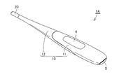
- FIG. 1 and 2 are perspective views of the electronic thermometer according to Embodiment 1 of the present invention.
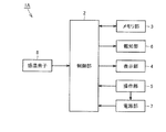
- FIG. 3 is a figure which shows the structure of the functional block of the electronic thermometer in this Embodiment.
- the external appearance structure of 1 A of electronic thermometers in this Embodiment and the structure of a functional block are demonstrated.
- an electronic thermometer 1A has a long outer shape in which one end portion in an axial direction is tapered, and a main body casing 10 as a housing and A cap body 20 is provided.
- the main body casing 10 mainly includes a first case body 11 and a second case body 12 which are divided into two along the axial direction, and the cap body 20 is positioned at the one end of the housing. It is assembled to the tip of the body 12.
- the first case body 11 and the second case body 12 are each composed of a cylindrical member made of a resin material such as ABS (Acrylonitrile Butadiene Styrene) resin, and these are assembled along the axial direction.
- the casing 10 has a long cylindrical shape as a whole.
- a display unit 4 is provided at a predetermined position on the upper surface of the main casing 10, and an operation unit 5 is provided at the other end of the main casing 10 opposite to the tapered one end. .
- the cap body 20 is composed of a hollow cylindrical member having a closed inner end made of a metal material such as a stainless alloy, and is measured by being sandwiched between measurement sites such as the armpit and the sublingual when measuring body temperature. It constitutes the warm section. A more detailed shape of the cap body 20 will be described later.
- the electronic thermometer 1A includes a control unit 2, a memory unit 3, a notification unit 6, a power supply unit 7, and a temperature sensing element 8 in addition to the display unit 4 and the operation unit 5 described above. I have.
- the control unit 2, the memory unit 3, the notification unit 6, the power supply unit 7, and the temperature sensitive element 8 are all housed in the casing described above.
- the control unit 2 is configured by, for example, a CPU (Central Processing Unit), and is a means for controlling the entire electronic thermometer 1A.
- the memory unit 3 is composed of, for example, a ROM (Read-Only Memory) or a RAM (Random-Access Memory), and stores a program for causing the control unit 2 or the like to execute a processing procedure for body temperature measurement. It is a means for storing results and the like.
- the display unit 4 is configured by a display panel such as an LCD (Liquid Crystal Display), and is a means for displaying measurement results and the like.
- the operation unit 5 is constituted by, for example, a push button, and is a means for accepting an operation by the user and inputting an external command to the control unit 2 and the power supply unit 7.
- the notification unit 6 is configured by, for example, a buzzer, and is a means for notifying the user that measurement has been completed or that a user operation has been accepted.
- the power supply unit 7 is constituted by, for example, a button battery, and is a means for supplying power to the control unit 2.
- the temperature sensing element 8 is configured by a thermistor 30 (see FIG. 4 and the like) assembled to the cap body 20, and the cap body 20 as a temperature measuring unit is sandwiched between measurement sites such as the armpit and the tongue. The means for detecting the temperature of the cap body 20.
- the control unit 2 includes a processing circuit for performing body temperature measurement, and performs body temperature measurement based on a program read from the memory unit 3. At that time, the control unit 2 calculates the body temperature as the measurement result by calculating the temperature information detected by the temperature sensing element 8, and controls the display unit 4 to display the calculated body temperature. Control is performed so that the calculated body temperature is stored in the memory unit 3, or control is performed so as to notify the user that the measurement is completed using the notification unit 6.
- the electronic thermometer 1A in the present embodiment employs a prediction formula as a body temperature measurement method
- the control unit 2 is, for example, a temperature measuring unit that is detected in a very short time from the measurement start time.
- the temperature rise information in the cap body 20 is detected using the temperature sensing element 8, and the actual body temperature is predicted by performing arithmetic processing according to a predetermined algorithm using the detected temperature rise information. And measure.
- body temperature will be measured in a very short time compared with the case where a measurement type
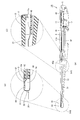
- FIG. 4A is a cross-sectional view of the electronic thermometer in this embodiment
- FIGS. 4B and 4C are enlarged views of regions IVB and IVC shown in FIG. 4A, respectively.
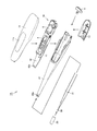
- FIG. FIG. 5 is an exploded perspective view of the electronic thermometer in the present embodiment.
- the electronic thermometer 1A includes the first case body 11, the second case body 12, and the cap body 20 as the above-described casing. And the thermistor 30 as the temperature sensing element 8 and the subassembly 40 in which various components are assembled.
- the subassembly 40 includes a subcase 41 in which various parts are assembled.
- a display panel constituting the display unit 4 a buzzer constituting the notification unit 6, a printed wiring board 42 provided with various processing circuits, and the power source unit 7 are provided.
- Examples include button batteries, terminal boards for electrical connection between various components, and accessory components attached to these components.
- the subassembly 40 is assembled to the first case body 11 using, for example, a screw (not shown) or the like.
- the thermistor 30 serving as the temperature sensing element 8 is a cuboid-shaped minute chip type thermistor, and a pair of lead wires 31 are drawn from the thermistor 30.
- the lead wire 31 is a wiring for electrically connecting the processing circuit provided on the printed wiring board 42 and the thermistor 30 described above. Note that the tips of the pair of lead wires 31 drawn out from the thermistor 30 are, for example, soldered (not shown) to each of the pair of connection electrodes 42a provided on the printed wiring board 42, as shown in FIG. ) Or the like.
- the thermistor 30 may be fixed to the cap body 20 with, for example, an adhesive (not shown) so that the temperature sensing part abuts on the inner peripheral surface of the cap body 20.
- the temperature sensing part is a detection part of the thermistor 30 made of a ceramic material whose electrical resistance value changes greatly according to a change in temperature.
- the fixing position of the thermistor 30 with respect to the cap body 20 is the inner peripheral surface of the cap body 20 at a portion located on the same surface side as the upper surface of the main body casing 10 provided with the display unit 4. It is preferable.
- the thermistor 30 is arranged on the body side by adjusting the orientation so that the display unit 4 can be visually recognized, It becomes possible to measure body temperature with higher accuracy and in a shorter time. A more detailed fixing position of the thermistor 30 will be described later.
- the subassembly 40 described above is accommodated in an accommodating space inside the main casing 10 constituted by the first case body 11 and the second case body 12.
- the thermistor 30 described above is accommodated in a hollow portion 24 provided inside the cap body 20.
- the lead wire 31 that connects the thermistor 30 and the printed wiring board 42 is arranged so as to mainly pass through the inside of the second case body 12.
- the fixed portion 12a is provided with a groove portion in an annular shape along the circumferential direction, and an adhesive 50 (see FIG. 4B) is applied to the groove portion, and in this state, the cap body 20 is fixed to the fixed portion 12a.
- the cap body 20 is assembled to the fixed part 12a by being extrapolated to be cured and the adhesive 50 being cured.
- a display window 11 a for making the display unit 4 visible is provided at a predetermined position of the first case body 11.
- a push button that constitutes the operation unit 5 described above is attached to the rear end.
- a fixed portion 12 a to which the cap body 20 is fixed is provided at the tip of the second case body 12, and the button battery as the power supply section 7 described above is provided at a predetermined position of the second case body 12.
- the battery cover 13 is detachably attached.
- FIG. 6A is a perspective view of a cap body of the electronic thermometer according to the present embodiment
- FIGS. 6B and 6C are cross-sectional views taken along lines VIB-VIB and VIC-VIC shown in FIG. 6A, respectively.
- FIG. 6C it demonstrates in full detail about the specific shape of the cap body 20 of the electronic thermometer 1A in this Embodiment.
- the cap body 20 constituting the temperature measuring unit is formed of a bottomed cylindrical member having a cylindrical portion 21, a bottom portion 22 and a curved corner portion 23, and a hollow portion 24 is formed therein.
- the cap body 20 has a flat outer shape in which the cross section of the cylindrical portion 21 orthogonal to the axial direction is substantially oval. By adopting the shape, the measurement site and the temperature measuring portion are measured. A device has been devised to maintain a stable contact state.
- the curved corner portion 23 is located between the tubular portion 21 and the bottom portion 22, and is composed of smooth curved portions that are respectively provided continuously to the tubular portion 21 and the bottom portion 22.
- the thermistor 30 described above is fixed to the cylindrical portion 21 located near the boundary between the curved corner portion 23 and the cylindrical portion 21 of the cap body 20. preferable.
- the temperature rise around the portion of the cap body 20 where the thermistor 30 is fixed efficiently transfers heat to the portion of the cap body 20 where the thermistor 30 is fixed. Therefore, the body temperature can be measured with higher accuracy and in a shorter time.
- the major axis and the minor axis in the cross section orthogonal to the axial direction of the cylindrical portion 21 are respectively A and B (see FIG. 6B), and the axial length of the cap body 20 is set.
- the thickness is C (see FIG. 6C)
- the major axis A, minor axis B, and axial length C satisfy the condition of 0.5 ⁇ B / A ⁇ 1.0.
- the cap body 20 is configured such that the minor axis B and the axial length C satisfy the condition of 3 ⁇ B ⁇ C.
- the cap body 20 having a shape satisfying such conditions stable contact between the measurement site and the temperature measuring unit at the time of measurement described above is realized, and the heat capacity of the cap body 20 and the measurement target are measured.
- the contact area between the region and the temperature measuring unit is optimized, and the body temperature can be measured in a shorter time. In other words, when the above conditions are not satisfied, there arises a problem that it becomes difficult to measure body temperature in a short time due to a decrease in contact area or an increase in heat capacity.
- the body temperature is measured with high accuracy. It has been confirmed by simulation results and results of verification tests on actual machines that the measurement time is reduced to 15 seconds.
- the major axis A of the cylindrical part 21 is preferably set to a range of 3 mm ⁇ A ⁇ 8 mm, for example, and the minor axis B of the cylindrical part 21 is For example, it is preferably set in a range of 3 mm ⁇ B ⁇ 4 mm, and the axial length C of the cap body 20 is preferably set in a range of 9 mm ⁇ C ⁇ 12 mm, for example.
- FIG. 7 is a view showing an assembly procedure of the electronic thermometer in the present embodiment
- FIG. 8 is a perspective view showing one state during the assembly. Next, with reference to these FIG. 7 and FIG. 8, the specific assembly procedure of the electronic thermometer 1A in this Embodiment is demonstrated.
- the thermistor 30 is first assembled to the cap body 20 (step S1). More specifically, the thermistor 30 is inserted into the hollow portion 24 provided inside the cap body 20, and the inserted thermistor 30 is bonded and fixed to a predetermined position on the inner peripheral surface of the cap body 20 using an adhesive. As a result, the thermistor 30 is assembled to the cap body 20.
- the inner peripheral surface of the cap body 20 is mirror-finished in advance, when the thermistor 30 is assembled to the cap body 20, the illumination light for confirming the state inside the cap body 20 is cap. Reflecting on the inner peripheral surface of the body 20 spreads to a deeper position, and the workability is greatly improved.
- the mirror finish include a mirror polishing process for polishing the inner peripheral surface of the cap body 20.
- the lead wire 31 is inserted into the second case body 12 (step S2). More specifically, the pair of lead wires 31 drawn out from the cap body 20 are inserted from the front end side of the second case body 12 toward the inside of the second case body 12, and the front ends thereof are disposed behind the second case body 12. Pull out from the edge. Thereafter, the cap body 20 is extrapolated to the fixed portion 12a provided at the tip of the second case body 12, and the cap body 20 is bonded and fixed to the second case body 12 using an adhesive.
- step S3 the subassembly 40 is assembled (step S3). More specifically, the above-described display panel, buzzer, printed wiring board 42, and the like are sequentially assembled to the sub case 41.
- step S4 the subassembly 40 is assembled to the first case body 11 (step S4). More specifically, the subassembly 40 manufactured in step S3 is assembled to the first case body 11 using screws or the like.
- the lead wire 31 is soldered to the connection electrode 42a of the printed wiring board 42 (step S5). More specifically, as shown in FIG. 8, the first case body 11 in which the subassembly 40 is assembled in step S4 is disposed adjacent to the second case body 12 in which the pair of lead wires 31 are inserted in step S2. Then, the tips of the pair of lead wires 31 drawn out from the second case body 12 are soldered to the pair of connection electrodes 42 a of the printed wiring board 42 assembled to the first case body 11.
- the tip which is a portion where the connection electrode 42a of the printed wiring board 42 is provided. Since it is comprised so that the near part may be exposed without being covered with the 1st case body 11, the soldering mentioned above can be performed efficiently and with sufficient workability.
- the margin of the length of the lead wire 31 necessary for performing the soldering work with good workability (that is, In the state shown in FIG. 8, the length of the lead wire 31 of the surplus portion drawn out from the second case body 12) can be minimized, so that the length of the lead wire 31 can be minimized. Therefore, the body temperature can be measured with higher accuracy and in a shorter time.
- the electronic thermometer 1A employs a configuration in which the connection electrode 42a is provided on the upper surface of the printed wiring board 42 (that is, the main surface on the side where the display unit 4 is located). A portion near the tip of the printed wiring board 42 provided with the connection electrode 42a is configured to protrude from the tip portion of the first case body 11 toward the cap body 20 side.
- the connection electrode 42a is provided on the lower surface of the printed wiring board 42 (that is, the main surface on the side where the display unit 4 is not located)
- the portion near the tip of the printed wiring board 42 is not necessarily the first. It is not necessary to configure the case body 11 so as to protrude from the distal end portion toward the cap body 20 side.
- the second case body 12 is assembled to the first case body 11 (step S6). More specifically, the front end portion of the first case body 11 and the rear end portion of the second case body 12 are combined, and the second case body 12 is fixed by fixing them using screws or the like in the combined state. Attach to the first case body 11. Subsequently, the push button as the operation unit 5 and the battery cover 13 are assembled to the first case body 11.
- thermometer 1A having the above-described structure is manufactured.
- thermometer 1A As described above, by using the electronic thermometer 1A in the present embodiment, an electronic thermometer having a simple configuration capable of measuring the body temperature with high accuracy and in a short time can be obtained. Further, with the downsizing of the cap body 20, it is assumed that the operation becomes difficult particularly in the process of assembling the thermistor 30 to the cap body 20, but by adopting the above-described assembly structure and assembly procedure, Since this can be easily assembled, a high-performance electronic thermometer can be manufactured while suppressing an increase in manufacturing cost.
- FIG. 9 is an enlarged exploded perspective view of the main part of the electronic thermometer according to Embodiment 2 of the present invention
- FIG. 10 is an enlarged cross-sectional view of the main part of the electronic thermometer according to the present embodiment. Below, with reference to these FIG. 9 and FIG. 10, the structure of the electronic thermometer 1B in this Embodiment is demonstrated.
- the fixed portion 12 a provided at the tip of the second case body 12 is connected to the cap body 20 from the fixed portion 12 a.
- An extending portion 12a1 is provided so as to protrude and extend toward the bottom portion 22 side.
- the extension part 12a1 is preferably formed integrally with the second case body 12 at the time of injection molding of the second case body 12, for example, and is accommodated in the hollow part 24 of the cap body 20 after assembly. Is done.
- the extending portion 12a1 is preferably configured to have a substantially flat plate shape as illustrated, and is provided on the lower surface side of the second case body 12. Further, the extended portion 12a1 is not in contact with the cap body 20 after assembly. By comprising in this way, it can suppress that a heat
- the extending part 12a1 reaches the portion where the thermistor 30 is arranged along the axial direction of the cap body 20 after assembly. That is, it is preferable that the axial length L2 of the extending portion 12a1 is slightly longer than the distance L1 from the tip of the fixed portion 12a to the thermistor 30.
- the cap body 20 and the second case body 12 are assembled upside down.
- the extending portion 12a1 comes into contact with the thermistor 30.
- the thermistor 30 fixed to the cap body 20 is detached from the cap body 20
- the removed thermistor 30 is detached from the cap body 20 together with the lead wires 31, and the cap body 20 and the second case body 12. It becomes possible to reliably distinguish the workpiece assembled with upside down as a defective product immediately at that time.
- FIG. 11 is an enlarged cross-sectional view of the main part showing one state during the assembly of the electronic thermometer in the present embodiment. Next, with reference to this FIG. 11, the effect obtained by providing the extension part 12a1 mentioned above in the 2nd case body 12 is demonstrated.
- the extension portion 12 a 1 is positioned at the distal end of the elongated second case body 12 when the cap body 20 after the thermistor 30 is assembled is assembled to the second case body 12. It becomes a guide for extrapolating the elongated cap body 20 to the fixed part 12a. That is, with the downsizing of the cap body 20, the workability of the work of extrapolating the cap body 20 to the fixed portion 12a is assumed to be deteriorated, but the extended portion 12a1 is used as the fixed portion 12a. By providing, the to-be-fixed part 12a becomes a guide and the workability
- the extension part 12a1 reflects the illumination light 100 for checking the internal state of the cap body 20 when the cap body 20 after the thermistor 30 is assembled is assembled to the second case body 12. It will also function as a reflection part. That is, as shown in FIG. 11, by illuminating the extension part 12 a 1 with illumination light 100 from an appropriate angle, the illumination light 100 is reflected on the surface of the extension part 12 a 1 to illuminate the inside of the cap body 20. It will be. Accordingly, the position of the thermistor 30 assembled inside the cap body 20 can be easily confirmed by visual observation or image processing using an imaging means, and the cap body 20 can be accurately discriminated up and down. It becomes possible to prevent the body 20 and the second case body 12 from being assembled upside down.
- the reflectance is increased by mirror-finishing the surface of the extending portion 12a1, or minute irregularities are provided on the surface of the extending portion 12a1.
- the illumination light 100 is efficiently scattered.
- the mirror finish a mirror polishing process for polishing the surface of the extension part 12a1, a mirror coating process for adding a glossy coating film to the surface of the extension part 12a1, or the second case body 12.
- thermometer 1B As described above, by using the electronic thermometer 1B in the present embodiment, it is possible to suppress the influence of deterioration in workability of the assembly work that occurs with the downsizing of the cap body 20 as low as possible. become. Therefore, an electronic thermometer having a simple configuration that can be easily assembled and can measure body temperature with high accuracy and in a short time can be obtained.
- 1A, 1B electronic thermometer 2 control unit, 3 memory unit, 4 display unit, 5 operation unit, 6 notification unit, 7 power supply unit, 8 temperature sensing element, 10 main body casing, 11 first case body, 11a display window, 12 2nd case body, 12a fixed part, 12a1 extension part, 13 battery cover, 20 cap body, 21 cylindrical part, 22 bottom part, 23 curved corner part, 24 hollow part, 30 thermistor, 31 lead wire, 40 subassembly , 41 subcase, 42 printed wiring board, 42a connection electrode, 50 adhesive, 100 illumination light.
Landscapes
- Physics & Mathematics (AREA)
- General Physics & Mathematics (AREA)
- Measuring Temperature Or Quantity Of Heat (AREA)
Abstract
電子体温計は、感温素子としてのサーミスタがその内部に配設されてなる有底筒状の金属製のキャップ体(20)を測温部として備える。キャップ体(20)は、筒状部(21)と、底部(22)と、湾曲コーナー部(23)とを含み、軸方向と直交する筒状部(21)の断面が略長円状である偏平な外形を有する。筒状部(21)の上記断面における長径をAとし、筒状部(21)の上記断面における短径をBとし、キャップ体(20)の軸方向長さをCとした場合に、長径A、短径Bおよび軸方向長さCは、0.5≦B/A<1.0でかつ3×B≦Cの条件を充足する。
Description
本発明は、電子体温計に関し、特に、短時間で体温を測定することが可能な予測式の電子体温計に関する。
一般に、腋下や舌下等の被測定部位に測温部を挟み込むことで体温の測定を可能にする電子体温計として、実測式のものと予測式のものとが知られている。予測式の電子体温計としては、複雑な構成でかつ高価な熱流式体温計を除くと、サーミスタ等からなる単一の感温素子を利用して体温を予測して測定する方式のものが主流となっている。
単一の感温素子を利用した予測式の電子体温計は、たとえば測定開始時点から極短時間のうちに検出される測温部における温度上昇の情報等を用いて所定のアルゴリズムに従って演算処理を行なうことにより、実際の体温を予測して測定するものであり、実測式の電子体温計よりも測定に要する時間が大幅に短縮される点において優れている。たとえば、近年においては、その測定時間が30秒またはそれ未満にまで短縮化されたものが実用化されている。
当該単一の感温素子を利用した予測式の電子体温計において、より短時間に体温を測定可能にするためには、アルゴリズムの改良はもちろんのこと、測温部の形状や大きさ等に代表される如くの電子体温計の構造上の改良も必要不可欠である。たとえば、特開2000-111414号公報(特許文献1)には、測温部を構成する金属製のキャップ体の形状や寸法等を改良することにより、その測定時間が20秒~30秒程度にまで短縮化できると記載されている。
ところで、電子体温計においては、当然ながら、高精度に体温が測定できることが求められる。すなわち、予測式の電子体温計において測定時間を短縮化する場合であっても、その測定精度が低下することは許されない。ここで、より高精度に体温を測定するためには、測定時において被測定部位と測温部とが安定的に接触した状態が維持されることが重要であり、当該観点を考慮に入れた場合には、測温部の外形は偏平形状とされることが好ましい。
しかしながら、上記特開2000-111414号公報においては、測温部の外形が略円柱状とされることを前提としており、これが偏平形状とされることについては何ら検討がなされていない。そのため、当該公報に開示の如くの電子体温計とした場合には、測定時において被測定部位と測温部とが安定的に接触した状態が維持されないおそれがあり、測定精度の点において問題が生じてしまう懸念がある。
また、上記公報においては、上述したように測定時間が20秒~30秒程度にまで短縮化できると記載されているが、さらなる測定時間の短縮化の要求も当然にある。
したがって、本発明は、高精度にかつ短時間に体温を測定することができる簡素な構成の電子体温計を提供することを目的とする。
また、本発明は、容易に組立てることが可能で、高精度にかつ短時間に体温を測定することができる簡素な構成の電子体温計を提供することを目的とする。
本発明に基づく電子体温計は、先端が閉塞された内部中空の測温部を有する筐体と、上記測温部を構成する有底筒状の金属製のキャップ体と、上記測温部の上記内部中空に配設された感温素子とを備えている。上記キャップ体は、筒状部と、底部と、上記筒状部および上記底部の間に位置してこれらに連続する湾曲コーナー部とを含んでおり、当該キャップ体の軸方向と直交する上記筒状部の断面が略長円状である偏平な外形を有している。上記筒状部の上記断面における長径をAとし、上記筒状部の上記断面における短径をBとし、上記キャップ体の軸方向長さをCとした場合に、上記長径A、上記短径Bおよび上記軸方向長さCは、0.5≦B/A<1.0の条件を充足するとともに、上記短径Bおよび上記軸方向長さCが、3×B≦Cの条件を充足している。
上記本発明に基づく電子体温計にあっては、上記短径Bが、3mm≦B≦4mmの条件を充足していることが好ましい。
上記本発明に基づく電子体温計にあっては、上記感温素子が、上記湾曲コーナー部と上記筒状部との境界寄りの部分に位置する上記筒状部に固定されていることが好ましい。
上記本発明に基づく電子体温計にあっては、上記感温素子が、セラミックス材料からなる感温部を含むチップタイプサーミスタにて構成されていることが好ましい。その場合には、上記感温部が上記キャップ体の内周面に当接するように、上記感温素子が上記キャップ体に固定されていることが好ましい。
上記本発明に基づく電子体温計は、測定結果を表示するための表示部をさらに備えていることが好ましい。その場合には、上記感温素子が、上記表示部が設けられた側の上記筐体の表面と同一表面側に位置する部分の上記キャップ体に固定されていることが好ましい。
上記本発明に基づく電子体温計にあっては、上記測温部を除く部分の上記筐体が、上記感温素子から引き出されたリード線と、当該リード線が接続される接続電極を含むプリント配線板とを収容するための収容空間を内部に含む本体ケーシングを有していることが好ましく、上記本体ケーシングは、上記プリント配線板が組付けられた第1ケース体と、当該第1ケース体および上記キャップ体を連結し、上記リード線が内部に挿通される第2ケース体とを含んでいることが好ましい。その場合には、上記プリント配線板が上記第1ケース体に組付けられた状態であってかつ上記第1ケース体が上記第2ケース体に連結されていない状態において、上記プリント配線板の上記接続電極が露出するように、上記第1ケース体および上記第2ケース体が構成されていることが好ましい。
上記本発明に基づく電子体温計にあっては、上記測温部を除く部分の上記筐体の先端に、上記キャップ体のうえ記筒状部が外挿されることで上記キャップ体が固定される被固定部が設けられていることが好ましい。その場合に、上記被固定部の先端に、当該被固定部から上記キャップ体の上記底部側に向けて延出された延出部がさらに設けられていることが好ましい。
上記本発明に基づく電子体温計にあっては、上記延出部が、上記キャップ体に非接触であることが好ましい。
上記本発明に基づく電子体温計にあっては、上記延出部が、上記キャップ体の軸方向に沿って上記感温素子が配置された部分にまで達していることが好ましい。
上記本発明に基づく電子体温計にあっては、上記延出部の表面が、鏡面仕上げされていることが好ましい。
上記本発明に基づく電子体温計にあっては、上記延出部の表面に、微小凹凸が設けられていることが好ましい。
上記本発明に基づく電子体温計にあっては、上記キャップ体の内周面が、鏡面仕上げされていることが好ましい。
本発明によれば、高精度にかつ短時間に体温を測定することができる簡素な構成の電子体温計とすることができる。
また、本発明によれば、容易に組立てることが可能で、高精度にかつ短時間に体温を測定することができる簡素な構成の電子体温計とすることができる。
以下、本発明の実施の形態について、図を参照して詳細に説明する。以下に示す実施の形態は、いずれも単一の感温素子を利用した予測式の電子体温計に本発明を適用した場合を例示するものである。なお、以下においては、同一または共通の部分について図中同一の符号を付し、その説明は繰り返さない。
(実施の形態1)
図1および図2は、本発明の実施の形態1における電子体温計の斜視図である。また、図3は、本実施の形態における電子体温計の機能ブロックの構成を示す図である。まず、これら図1ないし図3を参照して、本実施の形態における電子体温計1Aの外観構造および機能ブロックの構成について説明する。
図1および図2は、本発明の実施の形態1における電子体温計の斜視図である。また、図3は、本実施の形態における電子体温計の機能ブロックの構成を示す図である。まず、これら図1ないし図3を参照して、本実施の形態における電子体温計1Aの外観構造および機能ブロックの構成について説明する。
図1および図2に示すように、本実施の形態における電子体温計1Aは、軸方向の一端部が先細り形状とされた長尺状の外形を有しており、筐体としての本体ケーシング10およびキャップ体20を備えている。本体ケーシング10は、軸方向に沿って2分割された第1ケース体11および第2ケース体12を主として含んでおり、キャップ体20は、筐体の上記一端部に位置するように第2ケース体12の先端に組付けられている。
第1ケース体11および第2ケース体12は、たとえばいずれもABS(Acrylonitrile Butadiene Styrene)樹脂等の樹脂材料からなる筒状の部材からなり、軸方向に沿ってこれらが組付けられることにより、本体ケーシング10が全体として長尺筒状の形状を有している。本体ケーシング10の上面の所定位置には、表示部4が設けられており、本体ケーシング10の先細りした上記一端部とは反対側に位置する他端部には、操作部5が設けられている。
キャップ体20は、たとえばステンレス合金等の金属材料からなる一端が閉塞された内部中空の有底筒状の部材からなり、体温の測定に際してたとえば腋下や舌下等の被測定部位によって挟み込まれる測温部を構成している。なお、キャップ体20のより詳細な形状等については、後述することとする。
図3に示すように、本実施の形態における電子体温計1Aは、上述した表示部4および操作部5に加え、制御部2、メモリ部3、報知部6、電源部7および感温素子8を備えている。これら制御部2、メモリ部3、報知部6、電源部7および感温素子8は、いずれも上述した筐体の内部に収容されている。
制御部2は、たとえばCPU(Central Processing Unit)にて構成され、電子体温計1Aの全体を制御するための手段である。メモリ部3は、たとえばROM(Read-Only Memory)やRAM(Random-Access Memory)にて構成され、体温測定のための処理手順を制御部2等に実行させるためのプログラムを記憶したり、測定結果等を記憶したりするための手段である。
表示部4は、たとえばLCD(Liquid Crystal Display)等の表示パネルにて構成され、測定結果等を表示するための手段である。操作部5は、たとえば押し釦にて構成され、ユーザによる操作を受け付けてこの外部からの命令を制御部2や電源部7に入力するための手段である。報知部6は、たとえばブザーによって構成され、測定が終了したことやユーザの操作を受け付けたこと等をユーザに知らせるための手段である。
電源部7は、たとえばボタン電池によって構成され、制御部2に電力を供給するための手段である。感温素子8は、キャップ体20に組付けられたサーミスタ30(図4等参照)によって構成され、測温部としてのキャップ体20が腋下や舌下等の被測定部位に挟み込まれた状態において、当該キャップ体20の温度を検出するための手段である。
制御部2は、体温測定を実行するための処理回路を含んでおり、メモリ部3から読み出されたプログラムに基づいて体温測定を行なう。その際、制御部2は、感温素子8によって検出された温度情報を演算処理することで測定結果としての体温を算出し、算出した体温を表示部4にて表示するように制御したり、算出した体温をメモリ部3に記憶させるように制御したり、測定が終了したことを報知部6を用いてユーザに知らせるように制御したりする。
より詳細には、本実施の形態における電子体温計1Aは、体温測定方式として予測式を採用するものであり、制御部2は、たとえば測定開始時点から極短時間のうちに検出される測温部としてのキャップ体20における温度上昇の情報等を感温素子8を利用して検出し、検出された温度上昇の情報等を用いて所定のアルゴリズムに従って演算処理を行なうことにより、実際の体温を予測して測定する。これにより、本実施の形態における電子体温計1Aにあっては、実測式を採用した場合に比べ、極短時間のうちに体温が測定されることになる。
図4(A)は、本実施の形態における電子体温計の断面図であり、図4(B)および図4(C)は、それぞれ図4(A)に示す領域IVBおよび領域IVCを拡大した要部拡大断面図である。また、図5は、本実施の形態における電子体温計の分解斜視図である。次に、これら図4(A)ないし図4(C)および図5を参照して、本実施の形態における電子体温計1Aの内部構造ならびに組立構造について説明する。
図4(A)ないし図4(C)および図5に示すように、本実施の形態における電子体温計1Aは、上述した筐体としての第1ケース体11、第2ケース体12およびキャップ体20と、感温素子8としてのサーミスタ30と、各種構成部品が組付けられたサブアセンブリ40とによって主として構成されている。
サブアセンブリ40は、各種部品が組付けられたサブケース41を含んでいる。ここで、サブケース41に組付けられる各種部品としては、表示部4を構成する表示パネルや報知部6を構成するブザー、各種処理回路等が設けられたプリント配線板42、電源部7としてのボタン電池、各種部品間の電気的接続を図る端子板、およびこれら部品に付属される付属部品等が挙げられる。好適には、サブアセンブリ40は、たとえばビス(不図示)等を用いて第1ケース体11に組付けられる。
感温素子8としてのサーミスタ30は、直方体形状の微小なチップタイプサーミスタからなり、当該サーミスタ30からはリード線31が一対引き出されている。リード線31は、上述したプリント配線板42に設けられた処理回路とサーミスタ30とを電気的に接続するための配線である。なお、サーミスタ30から引き出された一対のリード線31の各々の先端は、図4(C)に示すように、プリント配線板42に設けられた一対の接続電極42aの各々にたとえば半田(不図示)等を用いて接続される。
図4(B)に示すように、サーミスタ30は、キャップ体20の内周面にその感温部が当接するように、たとえば接着剤(不図示)等によってキャップ体20に固定されることが好ましい。ここで、感温部とは、温度の変化に応じてその電気的な抵抗値が大きく変化するセラミック材料にて構成されたサーミスタ30の検出部位のことである。
ここで、サーミスタ30のキャップ体20に対する固定位置としては、図示するように、表示部4が設けられた本体ケーシング10の上面と同一表面側に位置する部分のキャップ体20の内周面であることが好ましい。このように構成することにより、たとえば測温部を腋下に挟み込んで測定する場合に、表示部4が視認できるように向きを調節することでサーミスタ30が胴体側に配置されることになり、より高精度にかつ短時間に体温を測定することが可能になる。なお、より詳細なサーミスタ30の固定位置については、後述することとする。
図4(A)および図5に示すように、上述したサブアセンブリ40は、第1ケース体11および第2ケース体12にて構成される本体ケーシング10の内部の収容空間に収容される。一方、上述したサーミスタ30は、キャップ体20の内部に設けられた中空部24に収容される。また、サーミスタ30とプリント配線板42とを接続するリード線31は、主として第2ケース体12の内部を挿通するように配置される。
図4(A)、図4(B)および図5に示すように、第2ケース体12の先端には、キャップ体20が外挿されることで当該キャップ体20が固定される被固定部12aが設けられている。被固定部12aには、周方向に沿って環状に溝部が設けられており、当該溝部に接着剤50(図4(B)参照)が塗布され、その状態においてキャップ体20が被固定部12aに外挿されて接着剤50が硬化させられることにより、キャップ体20が被固定部12aに組付けられる。
また、図4(A)および図5に示すように、第1ケース体11の所定位置には、表示部4を視認可能にするための表示窓11aが設けられており、第1ケース体11の後端には、上述した操作部5を構成する押し釦が取付けられる。また、第2ケース体12の先端には、キャップ体20が固定される被固定部12aが設けられており、第2ケース体12の所定位置には、上述した電源部7としてのボタン電池を交換可能にするために、着脱自在に電池カバー13が取付けられる。
なお、上述した本実施の形態における電子体温計1Aの組立構造を実現するための具体的な組立手順については、後述することとする。
図6Aは、本実施の形態における電子体温計のキャップ体の斜視図であり、図6Bおよび図6Cは、それぞれ図6Aに示すVIB-VIB線およびVIC-VIC線に沿った断面図である。次に、これら図6Aないし図6Cを参照して、本実施の形態における電子体温計1Aのキャップ体20の具体的な形状等について詳説する。
図6Aないし図6Cに示すように、測温部を構成するキャップ体20は、筒状部21、底部22および湾曲コーナー部23を有する有底筒状の部材からなり、内部に中空部24を有している。キャップ体20は、軸方向と直交する筒状部21の断面が略長円状である偏平な外形を有しており、当該形状を採用することで測定時において被測定部位と測温部とが安定的に接触した状態が維持されるように工夫がなされている。なお、湾曲コーナー部23は、筒状部21と底部22との間に位置しており、これら筒状部21および底部22にそれぞれ連続して設けられた滑らかな湾曲状の部位からなる。
ここで、図4(B)に示すように、上述したサーミスタ30は、キャップ体20の湾曲コーナー部23と筒状部21との境界寄りの部分に位置する筒状部21に固定されること好ましい。このように構成することにより、測定時において、キャップ体20のサーミスタ30が固定された部分の周囲における温度上昇が効率的にキャップ体20のサーミスタ30が固定された部分に伝熱するようになるため、より高精度にかつ短時間に体温を測定することが可能になる。
また、本実施の形態における電子体温計1Aにあっては、筒状部21の軸方向と直交する断面における長径および短径をそれぞれAおよびB(図6B参照)とし、キャップ体20の軸方向長さをC(図6C参照)とした場合に、これら長径A、短径Bおよび軸方向長さCが、0.5≦B/A<1.0の条件を充足するとともに、こられのうちの短径Bおよび軸方向長さCが、3×B≦Cの条件を充足するように、キャップ体20が構成されている。
このような条件を充足した形状のキャップ体20を用いることにより、上述した測定時における被測定部位と測温部との安定的な接触が実現された上に、キャップ体20の熱容量および被測定部位と測温部との間の接触面積等が最適化されることになり、より短時間での体温の測定が可能になる。換言すれば、上記条件が充足されていない場合には、接触面積が減少したり熱容量が増大したりすることによって短時間での体温測定が困難となってしまう問題が生じてしまう。
一例として、筒状部21の長径Aを4.6mmとし、短径Bを3.5mmとし、キャップ体20の軸方向長さCを11.0mmとした場合には、高い精度での体温測定が実現される上に測定時間が15秒にまで短縮化されることが、シミュレーション結果および実機における検証試験の結果によって確認されている。
なお、上述した条件を充足することを前提に、筒状部21の長径Aとしては、たとえば3mm<A≦8mmの範囲に設定されることが好ましく、筒状部21の短径Bとしては、たとえば3mm≦B≦4mmの範囲に設定されることが好ましく、またキャップ体20の軸方向長さCとしては、たとえば9mm≦C≦12mmの範囲に設定されることが好ましい。
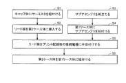
図7は、本実施の形態における電子体温計の組立手順を示す図であり、図8は、組立途中の一状態を示す斜視図である。次に、これら図7および図8を参照して、本実施の形態における電子体温計1Aの具体的な組立手順について説明する。
図7に示すように、本実施の形態における電子体温計1Aを組立てるに際しては、まずキャップ体20にサーミスタ30を組付ける(ステップS1)。より詳細には、キャップ体20の内部に設けられた中空部24にサーミスタ30を挿入するとともに、当該挿入したサーミスタ30を接着剤を用いてキャップ体20の内周面の所定位置に接着固定することにより、サーミスタ30をキャップ体20に組付ける。
ここで、キャップ体20の内周面を予め鏡面仕上げしておけば、当該サーミスタ30のキャップ体20への組付けの際に、キャップ体20の内部の状況を確認するための照明光がキャップ体20の内周面において反射されることでより奥の位置まで行き渡ることになり、作業性が大幅に向上することになる。ここで、鏡面仕上げとしては、キャップ体20の内周面を研磨する鏡面化研磨加工等が挙げられる。
次に、リード線31を第2ケース体12に挿入する(ステップS2)。より詳細には、キャップ体20から引き出された一対のリード線31を第2ケース体12の先端側から第2ケース体12の内部に向けて挿入し、その先端を第2ケース体12の後端から引き出す。その後、キャップ体20を第2ケース体12の先端に設けられた被固定部12aに外挿し、接着剤を用いてキャップ体20を第2ケース体12に接着固定する。
次に、サブアセンブリ40を組立てる(ステップS3)。より詳細には、サブケース41に、上述した表示パネルやブザー、プリント配線板42等を順次組付ける。
次に、第1ケース体11にサブアセンブリ40を組付ける(ステップS4)。より詳細には、ステップS3において製作されたサブアセンブリ40をビス等を用いて第1ケース体11に組付ける。
次に、リード線31をプリント配線板42の接続電極42aに半田付けする(ステップS5)。より詳細には、図8に示すように、ステップS2において一対のリード線31が挿通された第2ケース体12に、ステップS4においてサブアセンブリ40が組付けられた第1ケース体11を近接配置し、第2ケース体12から引き出された一対のリード線31の先端を第1ケース体11に組付けられたプリント配線板42の一対の接続電極42aに半田付けする。
その際、本実施の形態における電子体温計1Aにあっては、プリント配線板42が第1ケース体11に組付けられた状態において、プリント配線板42の接続電極42aが設けられた部分である先端寄りの部分が第1ケース体11によって覆われることなく露出した状態となるように構成されているため、上述した半田付けを効率的に作業性よく行なうことができる。
また、本実施の形態における電子体温計1Aの如くの組付構造および組付手順を採用することにより、半田付け作業を作業性よく行なうために必要となるリード線31の長さのマージン(すなわち、図8に示す状態において第2ケース体12から引き出された余剰部分のリード線31の長さ)を必要最小限に抑えることができるため、リード線31の長さを最小化することができる。したがって、より高精度にかつ短時間に体温を測定することが可能になる。
なお、本実施の形態における電子体温計1Aにあっては、プリント配線板42の上面(すなわち、表示部4が位置する側の主面)に接続電極42aが設けられる構成を採用しているため、接続電極42aが設けられたプリント配線板42の先端寄りの部分が第1ケース体11の先端部分からキャップ体20側に向けて突出するように構成している。しかしながら、プリント配線板42の下面(すなわち、表示部4が位置しない側の主面)に接続電極42aが設けられる構成を採用する場合には、必ずしもプリント配線板42の先端寄りの部分が第1ケース体11の先端部分からキャップ体20側に向けて突出するように構成する必要はない。
次に、図7に示すように、第2ケース体12を第1ケース体11に組付ける(ステップS6)。より詳細には、第1ケース体11の先端部分と第2ケース体12の後端部分とを組み合わせ、当該組み合わせた状態においてビス等を用いてこれらを固定することにより、第2ケース体12を第1ケース体11に組付ける。つづいて、第1ケース体11に操作部5としての押し釦および電池カバー13を組付ける。
以上の組付手順を経ることにより、上述した構造を備えた電子体温計1Aが製造されることになる。
以上において説明したように、本実施の形態における電子体温計1Aとすることにより、高精度にかつ短時間に体温を測定することができる簡素な構成の電子体温計とすることができる。また、キャップ体20の小型化に伴い、特にキャップ体20にサーミスタ30を組付ける工程において作業が困難になることが想定されるが、上述した組付構造および組付手順を採用することにより、これを容易に組立てることが可能となるため、製造コストの増大を抑制しつつ高性能の電子体温計を製造することが可能になる。
(実施の形態2)
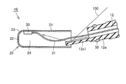
図9は、本発明の実施の形態2における電子体温計の要部拡大分解斜視図であり、図10は、本実施の形態における電子体温計の要部拡大断面図である。以下においては、これら図9および図10を参照して、本実施の形態における電子体温計1Bの構造について説明する。
図9は、本発明の実施の形態2における電子体温計の要部拡大分解斜視図であり、図10は、本実施の形態における電子体温計の要部拡大断面図である。以下においては、これら図9および図10を参照して、本実施の形態における電子体温計1Bの構造について説明する。
図9および図10に示すように、本実施の形態における電子体温計1Bにあっては、第2ケース体12の先端に設けられた被固定部12aに、当該被固定部12aからキャップ体20の底部22側に向けて突出して延びるように延出部12a1が設けられている。当該延出部12a1は、たとえば第2ケース体12の射出成形の際に当該第2ケース体12と同時に一体的に形成されることが好ましく、組立後においてキャップ体20の中空部24内に収容される。
延出部12a1は、図示するように略平板状の形状を有するように構成されていることが好ましく、第2ケース体12の下面側に設けられている。また、延出部12a1は、組立後においてキャップ体20に非接触である。このように構成することにより、測定時においてキャップ体20から延出部12a1に直接的に熱が伝熱してしまうことが抑制でき、測定時間の短縮化が妨げられることが防止できる。
図10に示すように、延出部12a1は、組立後においてキャップ体20の軸方向に沿ってサーミスタ30が配置された部分にまで達していることが好ましい。すなわち、延出部12a1の軸方向の長さL2は、被固定部12aの先端からサーミスタ30までの距離L1よりも僅かに長く構成されていることが好ましい。
このように構成すれば、サーミスタ30が組付けられた後のキャップ体20を第2ケース体12に組付ける際に、キャップ体20と第2ケース体12とが上下逆さまに組付けられた場合、当該延出部12a1がサーミスタ30に接触することになる。これにより、キャップ体20に固定されたサーミスタ30がキャップ体20から脱落することになり、脱落したサーミスタ30がリード線31ごとキャップ体20から外れることになり、キャップ体20と第2ケース体12とが上下逆さまに組付けられたワークをその時点で即座に不良品として確実に峻別することが可能になる。
図11は、本実施の形態における電子体温計の組立途中の一状態を示す要部拡大断面図である。次に、この図11を参照して、上述した延出部12a1を第2ケース体12に設けることによって得られる効果について説明する。
図11に示すように、延出部12a1は、サーミスタ30が組付けられた後のキャップ体20を第2ケース体12に組付ける際に、細長い形状の第2ケース体12の先端に位置する被固定部12aに、細長い形状のキャップ体20を外挿させるためのガイドとなる。すなわち、キャップ体20の小型化に伴って当該キャップ体20を被固定部12aに外挿する作業の作業性の悪化が想定されることになるが、当該延出部12a1を被固定部12aに設けることにより、被固定部12aがガイドとなって当該作業の作業性が向上することになる。
また、延出部12a1は、サーミスタ30が組付けられた後のキャップ体20を第2ケース体12に組付ける際に、キャップ体20の内部の状況を確認するための照明光100を反射する反射部として機能することにもなる。すなわち、図11に示すように、照明光100を適宜の角度から延出部12a1に照射することにより、延出部12a1の表面において当該照明光100が反射されてキャップ体20の内部を照明することになる。したがって、キャップ体20の内部に組付けられたサーミスタ30の位置を目視または撮像手段を用いた画像処理等によって確認し易くなり、キャップ体20の上下の判別が正確に行なえるようになってキャップ体20と第2ケース体12とが上下逆さまに組付けられることを未然に防止できるようにもなる。
なお、延出部12a1の上述した反射部としての機能を高めるためには、延出部12a1の表面を鏡面仕上げすることで反射率を高めるか、あるいは延出部12a1の表面に微小凹凸を設けることで照明光100が効率的に散乱するようにすることが好ましい。ここで、鏡面仕上げとしては、延出部12a1の表面を研磨する鏡面化研磨加工や、延出部12a1の表面に光沢を有する被覆膜を塗装により付加する鏡面塗装加工、第2ケース体12を射出成形する際に用いる金型の延出部12a1に対応する部分の表面を鏡面化研磨加工することで延出部12a1の表面を可能な限り鏡面化する加工方法等が挙げられる。
以上において説明したように、本実施の形態における電子体温計1Bとすることにより、キャップ体20の小型化に伴って発生する組付作業の作業性の悪化の影響を可能な限り低く抑えることが可能になる。したがって、容易に組立てることが可能で、高精度にかつ短時間に体温を測定することができる簡素な構成の電子体温計とすることができる。
なお、今回開示した上記各実施の形態はすべての点で例示であって、制限的なものではない。本発明の技術的範囲は請求の範囲によって画定され、また請求の範囲の記載と均等の意味および範囲内でのすべての変更を含むものである。
1A,1B 電子体温計、2 制御部、3 メモリ部、4 表示部、5 操作部、6 報知部、7 電源部、8 感温素子、10 本体ケーシング、11 第1ケース体、11a 表示窓、12 第2ケース体、12a 被固定部、12a1 延出部、13 電池カバー、20 キャップ体、21 筒状部、22 底部、23 湾曲コーナー部、24 中空部、30 サーミスタ、31 リード線、40 サブアセンブリ、41 サブケース、42 プリント配線板、42a 接続電極、50 接着剤、100 照明光。
Claims (12)
- 先端が閉塞された内部中空(24)の測温部を有する筐体と、
前記測温部を構成する有底筒状の金属製のキャップ体(20)と、
前記測温部の前記内部中空(24)に配設された感温素子(8)とを備え、
前記キャップ体(20)は、筒状部(21)と、底部(22)と、前記筒状部(21)および前記底部(22)の間に位置してこれらに連続する湾曲コーナー部(23)とを含み、当該キャップ体(20)の軸方向と直交する前記筒状部(21)の断面が略長円状である偏平な外形を有し、
前記筒状部(21)の前記断面における長径をAとし、前記筒状部(21)の前記断面における短径をBとし、前記キャップ体(20)の軸方向長さをCとした場合に、前記長径A、前記短径Bおよび前記軸方向長さCが、0.5≦B/A<1.0の条件を充足するとともに、前記短径Bおよび前記軸方向長さCが、3×B≦Cの条件を充足する、電子体温計。 - 前記短径Bが、3mm≦B≦4mmの条件を充足する、請求項1に記載の電子体温計。
- 前記感温素子(8)が、前記湾曲コーナー部(23)と前記筒状部(21)との境界寄りの部分に位置する前記筒状部(21)に固定されている、請求項1に記載の電子体温計。
- 前記感温素子(8)は、セラミックス材料からなる感温部を含むチップタイプサーミスタからなり、
前記感温部が前記キャップ体(20)の内周面に当接するように、前記感温素子(8)が前記キャップ体(20)に固定されている、請求項1に記載の電子体温計。 - 測定結果を表示するための表示部(4)をさらに備え、
前記感温素子(8)が、前記表示部(4)が設けられた側の前記筐体の表面と同一表面側に位置する部分の前記キャップ体(20)に固定されている、請求項1に記載の電子体温計。 - 前記測温部を除く部分の前記筐体は、前記感温素子(8)から引き出されたリード線(31)と、当該リード線(31)が接続される接続電極(42a)を含むプリント配線板(42)とを収容するための収容空間を内部に含む本体ケーシング(10)を有し、
前記本体ケーシング(10)は、前記プリント配線板(42)が組付けられた第1ケース体(11)と、当該第1ケース体(11)および前記キャップ体(20)を連結し、前記リード線(31)が内部に挿通される第2ケース体(12)とを含み、
前記プリント配線板(42)が前記第1ケース体(11)に組付けられた状態であって、かつ前記第1ケース体(11)が前記第2ケース体(12)に連結されていない状態において、前記プリント配線板(42)の前記接続電極(42a)が露出するように、前記第1ケース体(11)および前記第2ケース体(12)が構成されている、請求項1に記載の電子体温計。 - 前記測温部を除く部分の前記筐体の先端には、前記キャップ体(20)の前記筒状部(21)が外挿されることで前記キャップ体(20)が固定される被固定部(12a)が設けられ、
前記被固定部(12a)の先端に、当該被固定部(12a)から前記キャップ体(20)の前記底部(22)側に向けて延出された延出部(12a1)がさらに設けられている、請求項1に記載の電子体温計。 - 前記延出部(12a1)が、前記キャップ体(20)に非接触である、請求項7に記載の電子体温計。
- 前記延出部(12a1)が、前記キャップ体(20)の軸方向に沿って前記感温素子(8)が配置された部分にまで達している、請求項7に記載の電子体温計。
- 前記延出部(12a1)の表面が、鏡面仕上げされている、請求項7に記載の電子体温計。
- 前記延出部(12a1)の表面に、微小凹凸が設けられている、請求項7に記載の電子体温計。
- 前記キャップ体(20)の内周面が、鏡面仕上げされている、請求項1に記載の電子体温計。
Applications Claiming Priority (2)
| Application Number | Priority Date | Filing Date | Title |
|---|---|---|---|
| JP2011122039A JP2012251771A (ja) | 2011-05-31 | 2011-05-31 | 電子体温計 |
| JP2011-122039 | 2011-05-31 |
Publications (1)
| Publication Number | Publication Date |
|---|---|
| WO2012165090A1 true WO2012165090A1 (ja) | 2012-12-06 |
Family
ID=47258954
Family Applications (1)
| Application Number | Title | Priority Date | Filing Date |
|---|---|---|---|
| PCT/JP2012/061062 Ceased WO2012165090A1 (ja) | 2011-05-31 | 2012-04-25 | 電子体温計 |
Country Status (2)
| Country | Link |
|---|---|
| JP (1) | JP2012251771A (ja) |
| WO (1) | WO2012165090A1 (ja) |
Citations (4)
| Publication number | Priority date | Publication date | Assignee | Title |
|---|---|---|---|---|
| JP2000111414A (ja) * | 1998-10-09 | 2000-04-21 | Hyakuryaku Kigyo Kofun Yugenkoshi | 医療体温計 |
| JP2004264297A (ja) * | 2003-02-13 | 2004-09-24 | Terumo Corp | 電子体温計 |
| JP2007120963A (ja) * | 2005-10-25 | 2007-05-17 | Omron Healthcare Co Ltd | 電子体温計 |
| JP2009222677A (ja) * | 2008-03-18 | 2009-10-01 | Omron Healthcare Co Ltd | 電子体温計 |
-
2011
- 2011-05-31 JP JP2011122039A patent/JP2012251771A/ja not_active Withdrawn
-
2012
- 2012-04-25 WO PCT/JP2012/061062 patent/WO2012165090A1/ja not_active Ceased
Patent Citations (4)
| Publication number | Priority date | Publication date | Assignee | Title |
|---|---|---|---|---|
| JP2000111414A (ja) * | 1998-10-09 | 2000-04-21 | Hyakuryaku Kigyo Kofun Yugenkoshi | 医療体温計 |
| JP2004264297A (ja) * | 2003-02-13 | 2004-09-24 | Terumo Corp | 電子体温計 |
| JP2007120963A (ja) * | 2005-10-25 | 2007-05-17 | Omron Healthcare Co Ltd | 電子体温計 |
| JP2009222677A (ja) * | 2008-03-18 | 2009-10-01 | Omron Healthcare Co Ltd | 電子体温計 |
Also Published As
| Publication number | Publication date |
|---|---|
| JP2012251771A (ja) | 2012-12-20 |
Similar Documents
| Publication | Publication Date | Title |
|---|---|---|
| RU2454639C2 (ru) | Электронный термометр | |
| JP5540001B2 (ja) | モデル化を伴う多重温度測定 | |
| EP1783469B1 (en) | Electronic thermometer with flex circuit location | |
| RU2497441C2 (ru) | Электронный термометр | |
| RU2451269C1 (ru) | Электронный термометр | |
| JP2006503307A (ja) | 体温測定プローブ較正方法 | |
| US9316544B2 (en) | Electronic thermometer and method for manufacturing the same | |
| JP2012063301A5 (ja) | ||
| US20040071182A1 (en) | Thermometry probe calibration method | |
| JP2009300310A (ja) | 電子体温計 | |
| KR20070048123A (ko) | 센서 위치를 갖는 전자 온도계 | |
| JP6631583B2 (ja) | 温度センサ装置 | |
| WO2012165090A1 (ja) | 電子体温計 | |
| US7393137B2 (en) | Clinical thermometer | |
| CN103119409B (zh) | 电子体温计及其制造方法 | |
| JP3770265B2 (ja) | 赤外線温度計 | |
| JPH1048060A (ja) | 電子体温計 | |
| JP5220452B2 (ja) | 温度測定装置における保護構造 | |
| JP2009229130A (ja) | 電子体温計 | |
| JP2009229117A (ja) | 電子体温計 | |
| JP2013170935A (ja) | カバー付き電子体温計 | |
| WO2012105110A1 (ja) | 電子体温計 | |
| JP5420391B2 (ja) | 電子体温計 | |
| JP2006098180A (ja) | 電子体温計の製造方法 | |
| JP3206011U (ja) | 電源スイッチを有さない体温計 |
Legal Events
| Date | Code | Title | Description |
|---|---|---|---|
| 121 | Ep: the epo has been informed by wipo that ep was designated in this application |
Ref document number: 12793933 Country of ref document: EP Kind code of ref document: A1 |
|
| NENP | Non-entry into the national phase |
Ref country code: DE |
|
| 122 | Ep: pct application non-entry in european phase |
Ref document number: 12793933 Country of ref document: EP Kind code of ref document: A1 |