WO2012165048A1 - 給水設備 - Google Patents
給水設備 Download PDFInfo
- Publication number
- WO2012165048A1 WO2012165048A1 PCT/JP2012/059538 JP2012059538W WO2012165048A1 WO 2012165048 A1 WO2012165048 A1 WO 2012165048A1 JP 2012059538 W JP2012059538 W JP 2012059538W WO 2012165048 A1 WO2012165048 A1 WO 2012165048A1
- Authority
- WO
- WIPO (PCT)
- Prior art keywords
- water supply
- motor
- pump
- devices
- control device
- Prior art date
- Legal status (The legal status is an assumption and is not a legal conclusion. Google has not performed a legal analysis and makes no representation as to the accuracy of the status listed.)
- Ceased
Links
Images



Classifications
-
- F—MECHANICAL ENGINEERING; LIGHTING; HEATING; WEAPONS; BLASTING
- F04—POSITIVE - DISPLACEMENT MACHINES FOR LIQUIDS; PUMPS FOR LIQUIDS OR ELASTIC FLUIDS
- F04D—NON-POSITIVE-DISPLACEMENT PUMPS
- F04D15/00—Control, e.g. regulation, of pumps, pumping installations or systems
- F04D15/0088—Testing machines
-
- F—MECHANICAL ENGINEERING; LIGHTING; HEATING; WEAPONS; BLASTING
- F04—POSITIVE - DISPLACEMENT MACHINES FOR LIQUIDS; PUMPS FOR LIQUIDS OR ELASTIC FLUIDS
- F04D—NON-POSITIVE-DISPLACEMENT PUMPS
- F04D15/00—Control, e.g. regulation, of pumps, pumping installations or systems
- F04D15/0005—Control, e.g. regulation, of pumps, pumping installations or systems by using valves
- F04D15/0022—Control, e.g. regulation, of pumps, pumping installations or systems by using valves throttling valves or valves varying the pump inlet opening or the outlet opening
-
- F—MECHANICAL ENGINEERING; LIGHTING; HEATING; WEAPONS; BLASTING
- F04—POSITIVE - DISPLACEMENT MACHINES FOR LIQUIDS; PUMPS FOR LIQUIDS OR ELASTIC FLUIDS
- F04D—NON-POSITIVE-DISPLACEMENT PUMPS
- F04D15/00—Control, e.g. regulation, of pumps, pumping installations or systems
- F04D15/02—Stopping of pumps, or operating valves, on occurrence of unwanted conditions
- F04D15/029—Stopping of pumps, or operating valves, on occurrence of unwanted conditions for pumps operating in parallel
Definitions
- the present invention relates to a water supply facility that includes a plurality of water supply devices each including a backflow prevention valve, a pump, and the like, and these water supply devices are connected in parallel to each other via a water pipe.
- FIG. 4 is a schematic conceptual diagram showing a conventional example of this type of water supply equipment.
- 2 sets of water supply apparatuses are illustrated as said multiple sets of water supply apparatus.
- the water supply equipment 1 includes motor drive devices 13 and 23 that drive motors (12a and 22a) as AC motors (ACM) that form the backflow prevention valves 11 and 21, pumps 12 and 22, and pumps 12 and 22, respectively.
- the water supply apparatus 10 and 20 which consists of, and the pump control apparatus 2 which controls the operation state of the water supply apparatuses 10 and 20 via the motor drive devices 13 and 23 are shown.
- FIG. 5 is a detailed circuit configuration diagram of the motor drive device 23 shown in FIG.
- 31 is an input contactor
- 32 is an inverter formed of a forward conversion circuit and an inverse conversion circuit as shown
- 33 is an output contactor.
- this motor drive device 23 first, when the input contactor 31 is closed in response to the input command to the input contactor 31 from the pump control device 2, the input voltage is applied to the inverter 32 from the AC power source such as a commercial power source. Based on the operation command from the pump control device 2 to the inverter 32 and the frequency setting corresponding to the starting frequency of the motor 22a, the output of the inverter 32 has an output voltage of a frequency / voltage corresponding to this frequency setting. appear.
- Patent Document 1 In order to deal with such a problem, for example, what is disclosed in Patent Document 1 is known.
- the solution in Patent Document 1 is a gate valve around each check valve.
- a dedicated device such as a pressure sensor, which increases the cost of the entire water supply facility due to an increase in the number of parts.
- Patent Document 1 can detect a failure of the backflow check valve, there is a problem that the operation must be continued with a pressure loss until the failed backflow check valve is replaced. It was.
- the object of the present invention is to solve the above-mentioned problems, detect a failure of the backflow prevention valve without additionally installing a dedicated device, and generate a pressure loss even if a failure occurs in the backflow prevention valve. It is to provide a water supply facility that can be restored without any trouble.
- a plurality of water supply devices each including a backflow prevention valve, a pump, and a motor drive device that drives a motor forming the pump, and these water supply devices are connected in parallel via a water distribution pipe,
- a failure of the backflow prevention valve is detected by monitoring whether or not the motor of the pump control device stopped by a command from the pump control device is reversely rotated.
- 2nd invention is the water supply equipment of said 1st invention, Whether the motor is rotating in reverse is monitored when the stopped water supply device is started.
- 3rd invention is the water supply equipment of said 1st invention, Whether the motor is rotating in reverse is monitored at a preset time interval for the water supply apparatus that is stopped.
- 4th invention is the water supply equipment of said 1st invention,
- the reverse rotation of the motor is detected based on the terminal voltage of the primary winding of the motor or the terminal voltage of the primary winding of the motor and the primary winding current.
- a fifth aspect of the present invention provides the water supply facility according to any one of the first to fourth aspects, When it is detected that the motor forming any one of the pumps is rotating in reverse, the water supply device that was in operation is temporarily stopped by a command from the pump control device, and then it is in operation. The water supply device and the water supply device that detects the failure of the check valve are restarted at the same time.
- the backflow prevention valve of the water supply device in order to detect the malfunction of the backflow prevention valve of the water supply device, no special instrument is required. As a result, the price increase of the entire water supply facility is suppressed, and the malfunction of the backflow prevention valve is detected.
- all the water supply devices are temporarily stopped once, and then all the water supply devices are restarted at the same time so that this water supply facility can be temporarily restored. The robustness of the entire water supply facility can be improved.
- FIG. 1 Typical conceptual block diagram of the water supply equipment which shows the Example of this invention Partial detailed circuit configuration diagram of FIG. Flowchart for explaining the operation of FIG. Schematic conceptual diagram of water supply equipment showing a conventional example Partial detailed circuit configuration diagram of FIG.
- FIG. 1 is a schematic conceptual configuration diagram of a water supply facility showing an embodiment of the present invention.
- components having the same functions as those of the conventional configuration shown in FIG. 4 are denoted by the same reference numerals.
- two sets of water supply apparatuses are illustrated as the plurality of sets of water supply apparatuses.
- the water supply facility 3 shown in FIG. 1 includes water supply devices 15 and 25 in which the motor drive devices 13 and 23 are changed to the motor drive devices 16 and 26 in place of the conventional water supply devices 10 and 20. Further, a pump control device 4 is provided instead of the pump control device 2.
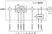
- FIG. 2 is a detailed circuit configuration diagram of the motor drive device 26 shown in FIG.
- components having the same functions as those of the conventional motor driving device 23 shown in FIG. 5 are denoted by the same reference numerals, and description thereof is omitted here.
- the motor drive device 26 shown in FIG. 2 includes an input contactor 31, an inverter 32, and an output contactor 33, as well as a current detector 34 that detects the primary winding current of the motor 22a (the output current of the inverter 32).
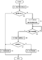
- the monitoring circuit 35 receives a monitoring command from the pump control device 4 while the water supply device 25 is stopped by a command from the pump control device 4, the terminal voltage of the motor 22a is read (step S1). Whether it is zero or not is confirmed (step S2).
- step S2 branch Y
- the motor 22a is a synchronous motor, and the check valve 21 has failed and the motor 22a is rotating in reverse. This is transmitted to the pump controller 4.
- step S4 If the read terminal voltage is substantially zero (step S2, branch N), it is recognized that the motor 22a is a synchronous motor and is stopped or the motor 22a is an induction motor.
- step S4 the input command to the input contactor 31, the operation command and frequency setting to the inverter 32, and the input command to the output contactor 33 are sequentially issued via the pump control device 4, It waits for an AC voltage having a frequency (approximately several hertz) and a voltage lower than that at the time of startup in the normal phase rotation direction to be applied to the motor 22a (step S5, branch N).
- step S6 When the AC voltage is applied to the motor 22a (step S5, branch Y), the applied voltage to the motor 22a and the motor current via the current detector 34 are sequentially read by sampling at a time interval of about 10 milliseconds. (Step S6).
- step S7 From the read voltage change and current change of the motor 22a, the phase relationship is grasped. If the motor 22a is in a braking state (step S7, branch Y), the motor 22a is an induction motor, and Since the check valve 21 is broken and it is determined that the motor 22a is rotating in reverse, the process proceeds to step S3, and this is transmitted to the pump control device 4.
- step S7, branch N If the motor 22a is in a driving state (step S7, branch N), it is determined that the motor 22a is normal and the backflow prevention valve 21 is normal. It transmits to the control apparatus 4.
- the monitoring circuit 35 may monitor whether or not the motor 22a is reversely rotated when the stopped water supply device is activated, or set in advance.
- the monitoring circuit 35 may monitor whether or not the motor 22a is periodically reversed at time intervals.
- step S3 when the state signal indicating that the motor 22a is reversely rotated is transmitted from the monitoring circuit 35 to the pump control device 4 while the water supply device 25 is stopped, the pump control device 4 that has received this signal receives the backflow prevention valve 21. Indicates that is malfunctioning.
- the pump control device 4 that has received the notification that the check valve 21 is out of order temporarily stops all the water supply devices 15 that are currently operating, stops the water supply device 15 that is currently operating, The water supply device 25 in which the backflow prevention valve 21 is detected to be broken together with the water supply device 15 is restarted simultaneously. This makes it possible to perform a temporary restoration operation while maintaining the function as a water supply facility.
- the water supply device 15 in operation is temporarily stopped in order to reliably start the water supply device 25 in which the check valve 21 is broken. That is, if the water supply device 15 in operation is not stopped, the water supply device 25 in which the backflow prevention valve 21 is broken may not be able to start normally due to the backflow pressure from the discharge port, and the water supply device 15 in operation is By stopping, the backflow pressure from the discharge port is relaxed, and the water supply device 25 in which the backflow prevention valve 21 is broken is surely started.
- the motor drive circuit 15 has the same function as the above-described monitoring circuit 35. Further, in this embodiment, two sets of water supply devices are illustrated, but three or more sets of water supply devices can be similarly realized by providing a monitoring circuit in each motor drive circuit.
Landscapes
- Engineering & Computer Science (AREA)
- Mechanical Engineering (AREA)
- General Engineering & Computer Science (AREA)
- Control Of Non-Positive-Displacement Pumps (AREA)
- Control Of Positive-Displacement Pumps (AREA)
Abstract
【課題】逆流阻止弁,ポンプなどからなる給水装置を複数組備え、これらの給水装置が互いに配水管を介して並列結合された給水設備において、逆流阻止弁の異常検知を容易にする。 【解決手段】給水設備3は、逆流阻止弁11,21、ポンプ12,22、ポンプ12,22を形成するモータ(12a,22a)を駆動するモータ駆動装置15,25からなる給水装置15,25と、モータ駆動装置15,25を介して給水装置15,25の動作状態を制御するポンプ制御装置4とから構成され、モータ駆動装置15,25に新たに備えた監視回路により、モータ12a,22aの何れかが逆転していることを検知するために特別な器具を必要とせず、その結果、給水設備3の価格上昇も僅かにし、また、前記検知回路により逆転が検知されたときには、ポンプ制御装置4から指令により、全給水装置を一旦完全停止させ、その後、全給水装置を同時再起動させるようにして、この給水設備3の一時的な復旧運転が可能とし、頑健性の向上を図るようにしている。
Description
この発明は、逆流阻止弁,ポンプなどからなる給水装置を複数組備え、これらの給水装置が互いに配水管を介して並列結合された給水設備に関する。
図4は、この種の給水設備の従来例を示す模式的概念構成図である。なお、この図においては、前記複数組の給水装置として、2組の給水装置を例示している。
すなわち、この給水設備1には、逆流阻止弁11,21、ポンプ12,22、ポンプ12,22を形成する交流電動機(ACM)としてのモータ(12a,22a)を駆動するモータ駆動装置13,23からなる給水装置10,20と、モータ駆動装置13,23を介して給水装置10,20の動作状態を制御するポンプ制御装置2とが示されている。
図5は、図4に示したモータ駆動装置23の詳細回路構成図である。この図において、31は入力コンタクタ、32は図示のように順変換回路,逆変換回路から形成されるインバータ、33は出力コンタクタである。
このモータ駆動装置23では、先ず、ポンプ制御装置2からの入力コンタクタ31への投入指令に対応して入力コンタクタ31が閉路すると、商用電源などの交流電源から入力電圧がインバータ32に印加され、次に発せられるポンプ制御装置2からのインバータ32への運転指令とモータ22aの起動周波数に対応した周波数設定とに基づいてインバータ32の出力には、この周波数設定に対応した周波数・電圧の出力電圧が発生する。
次に、ポンプ制御装置2からの出力コンタクタ33への投入指令に対応して出力コンタクタ33が閉路することにより、前記出力電圧がポンプ22を形成するモータ22aに印加されて、ポンプ22が回転を開始し、その後の前記周波数設定の増大に伴って、インバータ32の出力電圧の周波数・電圧が増大し、ポンプ22が所定の回転数に達することで、ポンプ22の起動が完了し、この給水装置20は通常の給水状態に入る。
このとき、インバータ32の動作状態として、例えば、過電流,過負荷などが発生すると、この状態を異常信号としてポンプ制御装置2に伝達するようにしている。なお、モータ駆動装置13もモータ駆動装置23と同じ構成であるので、ここでの説明は省略する。
図4に示した従来の給水設備1において、給水装置10,20それぞれに備える逆流阻止弁11,21は、繰り返し印加される圧力に起因する経年劣化により、作動故障が生ずることが知られている。
この作動故障が発生した逆流阻止弁側の給水装置が停止中の場合、例えば、図4において作動故障が発生している逆流阻止弁21側の給水装置20が停止中の場合には、本来、吸込口から給水装置10を介して吐出口側に供給されるはずの液体の一部が故障した逆流阻止弁21を介して、吸込口側に回り込むこととなり、その結果、圧力ロス並びに吸込口側に汚染が発生するという問題点があった。
しかしながら、逆流阻止弁の作動状況は、その構造上、外部から目視点検が不可能であるため、保守点検するためには給水装置を停止させる必要があった。
このような問題点に対処するために、例えば、上記特許文献1に開示されているものが知られているが、この特許文献1での解決策は、各逆流阻止弁の周辺に、仕切り弁,圧力センサなどの専用の器具を追加設置する必要があり、部品点数の増加による給水設備全体のコストアップとなる。さらに、特許文献1では、逆流阻止弁の故障を検知することはできるものの、故障した逆流阻止弁を交換するまでの間は圧力ロスが発生したままで運転を継続しなければならないという問題があった。
この発明の目的は、上記問題を解決し、専用の機器を追加設置することなく逆流阻止弁の故障を検知することができ、また、逆流阻止弁に故障が発生しても圧力ロスを発生することなく復旧運転が可能な給水設備を提供することにある。
この第1の発明は、逆流阻止弁,ポンプ,該ポンプを形成するモータを駆動するモータ駆動装置からなる給水装置を複数組と、これらの給水装置は互いに配水管を介して並列結合すると共に、それぞれの前記モータ駆動装置を介して個々の給水装置の動作状態を制御するポンプ制御装置とを備えた給水設備において、
前記ポンプ制御装置から指令により停止している前記ポンプ制御装置のモータが逆転しているか否かを監視して前記逆流阻止弁の故障を検知することを特徴とする。
前記ポンプ制御装置から指令により停止している前記ポンプ制御装置のモータが逆転しているか否かを監視して前記逆流阻止弁の故障を検知することを特徴とする。
第2の発明は、前記第1の発明の給水設備において、
前記モータが逆転しているか否かの監視を、停止中の前記給水装置を起動する際に行うことを特徴とする。
前記モータが逆転しているか否かの監視を、停止中の前記給水装置を起動する際に行うことを特徴とする。
また、第3の発明は、前記第1の発明の給水設備において、
前記モータが逆転しているか否かの監視を、停止中の前記給水装置に対し予め設定した時間間隔で行うことを特徴とする。
前記モータが逆転しているか否かの監視を、停止中の前記給水装置に対し予め設定した時間間隔で行うことを特徴とする。
また第4の発明は、前記第1の発明の給水設備において、
前記モータの逆転は該モータの一次巻線の端子電圧、又は該モータの一次巻線の端子電圧と一次巻線電流とに基づいて検知するようにしたことを特徴とする。
前記モータの逆転は該モータの一次巻線の端子電圧、又は該モータの一次巻線の端子電圧と一次巻線電流とに基づいて検知するようにしたことを特徴とする。
さらに第5の発明は、前記第1~4のうちの何れかの発明の給水設備において、
前記何れかのポンプを形成するモータが逆回転していることが検知されたときには、前記ポンプ制御装置から指令により、運転中であった給水装置を一旦完全停止させ、その後、運転中であった給水装置と逆流阻止弁の故障を検知した給水装置とを同時再起動させるようにしたことを特徴とする。
前記何れかのポンプを形成するモータが逆回転していることが検知されたときには、前記ポンプ制御装置から指令により、運転中であった給水装置を一旦完全停止させ、その後、運転中であった給水装置と逆流阻止弁の故障を検知した給水装置とを同時再起動させるようにしたことを特徴とする。
この発明によれば、給水装置の逆流阻止弁の不具合を検知するために、特別な器具を必要とせず、その結果、給水設備全体の価格上昇も抑制され、また、逆流阻止弁の不具合が検知されたときには、ポンプ制御装置から指令により、全給水装置を一旦完全停止させ、その後、全給水装置を同時再起動させるようにして、この給水設備の一時的な復旧運転が可能となることから、給水設備全体の頑健性の向上を図ることができる。
図1は、この発明の実施の形態を示す給水設備の模式的概念構成図であり、この図において、図4に示した従来例構成と同一機能を有するものには同一符号を付している。さらに、この図においても、前記複数組の給水装置として、2組の給水装置を例示している。
すなわち、図1に示した給水設備3には、従来の給水装置10,20に代えて、モータ駆動装置13,23がモータ駆動装置16,26に変更された給水装置15,25が備えられ、また、ポンプ制御装置2に代えて、ポンプ制御装置4が備えられている。
図2は、図1に示したモータ駆動装置26の詳細回路構成図である。この図において、図5に示した従来のモータ駆動装置23と同一機能を有するものには同一符号を付して、ここでは、その説明を省略する。
すなわち、図2に示したモータ駆動装置26には、入力コンタクタ31,インバータ32,出力コンタクタ33の他に、モータ22aの一次巻線電流(インバータ32の出力電流)を検出する電流検出器34と、モータ22aの一次巻線の端子電圧(インバータ32の出力電圧)、あるいは電流検出器34の出力とモータ22aの一次巻線の端子電圧とに基づいてモータ22aの逆転を検知する監視回路35とが追加設置されている。なお、モータ駆動装置16の構成もモータ駆動装置26と同じ構成であるので、以下ではモータ駆動装置26により説明する。
このモータ駆動装置26では、ポンプ制御装置4からの入力コンタクタ31への投入指令と、インバータ32への運転指令および周波数設定と、出力コンタクタ33への投入指令とに基づく通常の動作は、先述のモータ駆動装置23と同じである。
図2に示した監視回路35の動作を、図3に示すフローチャートを参照しつつ、以下に説明をする。
先ず、ポンプ制御装置4から指令により給水装置25が停止中に、ポンプ制御装置4からの監視指令を監視回路35が受信すると、モータ22aの端子電圧を読込み(ステップS1)、この端子電圧がほぼ零か否かを確認する(ステップS2)。
前記端子電圧が零でなければ(ステップS2、分岐Y)、モータ22aが同期電動機であり、且つ、逆流阻止弁21が故障してモータ22aが逆転中であると認定されるので、ステップS3に移り、このことをポンプ制御装置4に送信する。
また、前記読込んだ端子電圧がほぼ零であれば(ステップS2、分岐N)、モータ22aが同期電動機であり、且つ、停止中か、または、モータ22aが誘導電動機であると認定されるので、ステップS4に移り、ポンプ制御装置4を介して、入力コンタクタ31への投入指令と、インバータ32への運転指令および周波数設定と、出力コンタクタ33への投入指令とが順次発せられて、先述の通常の相回転方向で起動時より低い周波数(数ヘルツ程度)・電圧の交流電圧がモータ22aに印加されるのを待つ(ステップS5、分岐N)。
前記交流電圧がモータ22aに印加されると(ステップS5、分岐Y)、モータ22aへの印加電圧と、電流検出器34を介したモータ電流とを10ミリ秒程度の時間間隔のサンプリングで順次読込む(ステップS6)。
この読込んだモータ22aの電圧の変化と電流の変化とから、その位相関係を把握し、モータ22aが制動状態であれば(ステップS7、分岐Y)、モータ22aが誘導電動機であり、且つ、逆流阻止弁21が故障してモータ22aが逆転中であると認定されるので、ステップS3に移り、このことをポンプ制御装置4に送信する。
また、モータ22aが駆動状態であれば(ステップS7、分岐N)、モータ22aが正常であり、且つ、逆流阻止弁21も正常であると認定されるので、ステップS8に移り、このことをポンプ制御装置4に送信する。
なお、停止中の給水装置25に対して、停止中の給水装置を起動する際にモータ22aが逆転しているか否かを上述の監視回路35により監視するようにしてもよいし、予め設定した時間間隔で定期的にモータ22aが逆転しているか否かを上述の監視回路35により監視するようにしてもよい。
また、上記ステップS3において、給水装置25が停止中に監視回路35からモータ22aが逆転している状態信号をポンプ制御装置4に送信すると、この信号を受信したポンプ制御装置4では逆流阻止弁21が故障していることを外部表示する。一方、逆流阻止弁21が故障している通知を受けたポンプ制御装置4は、現在運転中の給水装置15を全て一旦停止させ、運転中の給水装置15を停止させた後、この運転中であった給水装置15とともに逆流阻止弁21が故障していることが検知された給水装置25を同時に再起動する。これにより給水設備としての機能を維持しつつ、一時的な復旧運転を行うことが可能になる。
ここで、運転中の給水装置15を一旦停止させるのは、逆流阻止弁21が故障している給水装置25を確実に起動させるためである。すなわち、運転中の給水装置15を停止させない場合、逆流阻止弁21が故障している給水装置25は、吐出口からの逆流圧力により正常に起動できない可能性があり、運転中の給水装置15を停止させることによって吐出口からの逆流圧力を緩和し、逆流阻止弁21が故障している給水装置25を確実に起動させるものである。
なお、モータ駆動回路15にも上述の監視回路35と同様の機能が備えられている。また、この実施の形態では2組の給水装置を例示しているが、3組以上の給水装置でもそれぞれのモータ駆動回路に監視回路を設けることにより同様に実現可能である。
従って、モータ12a,22aの何れかが逆転していることを検知するために、特別な器具を必要とせず、その結果、給水設備3の価格上昇も僅かであり、また、検知されたときには、ポンプ制御装置4から指令により、全給水装置を一旦完全停止させ、その後、運転中であった給水装置15とともに逆流阻止弁21が故障していることが検知された給水装置25を同時再起動させるようにして、この給水設備3の一時的な復旧運転が可能となり、頑健性の向上を図ることができる。
1,3…給水設備、2,4…ポンプ制御装置、10,15,20,25…給水装置、11,21…逆流阻止弁、12,22…ポンプ、12a,22a…モータ、13,16,23,26…モータ駆動装置、31…入力コンタクタ、31…インバータ、33…出力コンタクタ、34…電流検出器、35…監視回路。
Claims (5)
- 逆流阻止弁,ポンプ,該ポンプを形成するモータを駆動するモータ駆動装置からなる給水装置を複数組と、これらの給水装置は互いに配水管を介して並列結合すると共に、それぞれの前記モータ駆動装置を介して個々の給水装置の動作状態を制御するポンプ制御装置とを備えた給水設備において、
前記ポンプ制御装置から指令により停止している前記ポンプ制御装置のモータが逆転しているか否かを監視して前記逆流阻止弁の故障を検知することを特徴とする給水設備。 - 請求項1に記載の給水設備において、
前記モータが逆転しているか否かの監視を、停止中の前記給水装置を起動する際に行うことを特徴とする給水設備。 - 請求項1に記載の給水設備において、
前記モータが逆転しているか否かの監視を、停止中の前記給水装置に対し予め設定した時間間隔で行うことを特徴とする給水設備。 - 請求項1に記載の給水設備において、
前記モータの逆転は該モータの一次巻線の端子電圧、又は該モータの一次巻線の端子電圧と一次巻線電流とに基づいて検知するようにしたことを特徴とする給水設備。 - 請求項1乃至請求項4の何れか1項に記載の給水設備において、
前記何れかのポンプを形成するモータが逆回転していることが検知されたときには、前記ポンプ制御装置から指令により、運転中であった給水装置を一旦完全停止させ、その後、運転中であった給水装置と逆流阻止弁の故障を検知した給水装置とを同時再起動させるようにしたことを特徴とする給水設備。
Priority Applications (1)
| Application Number | Priority Date | Filing Date | Title |
|---|---|---|---|
| CN201280001955.8A CN103026073B (zh) | 2011-05-27 | 2012-04-06 | 供水设备 |
Applications Claiming Priority (2)
| Application Number | Priority Date | Filing Date | Title |
|---|---|---|---|
| JP2011118929A JP5782835B2 (ja) | 2011-05-27 | 2011-05-27 | 給水設備 |
| JP2011-118929 | 2011-05-27 |
Publications (1)
| Publication Number | Publication Date |
|---|---|
| WO2012165048A1 true WO2012165048A1 (ja) | 2012-12-06 |
Family
ID=47258913
Family Applications (1)
| Application Number | Title | Priority Date | Filing Date |
|---|---|---|---|
| PCT/JP2012/059538 Ceased WO2012165048A1 (ja) | 2011-05-27 | 2012-04-06 | 給水設備 |
Country Status (3)
| Country | Link |
|---|---|
| JP (1) | JP5782835B2 (ja) |
| CN (1) | CN103026073B (ja) |
| WO (1) | WO2012165048A1 (ja) |
Families Citing this family (4)
| Publication number | Priority date | Publication date | Assignee | Title |
|---|---|---|---|---|
| CN105201892A (zh) * | 2015-10-28 | 2015-12-30 | 上海澎阳太阳能泵业有限公司 | 水泵正反转检测方法 |
| CN107978079B (zh) * | 2016-10-25 | 2021-07-13 | 富士电机株式会社 | 饮料供给装置 |
| JP7463922B2 (ja) * | 2020-09-14 | 2024-04-09 | ニデックパワートレインシステムズ株式会社 | 油圧供給装置 |
| JP2024101390A (ja) * | 2023-01-17 | 2024-07-29 | 株式会社川本製作所 | 給水装置 |
Citations (3)
| Publication number | Priority date | Publication date | Assignee | Title |
|---|---|---|---|---|
| JPH0379900A (ja) * | 1989-08-18 | 1991-04-04 | Nippo Valve Kogyo Kk | 異常検知制御装置付き減圧式逆流防止装置 |
| JP4175912B2 (ja) * | 2003-02-17 | 2008-11-05 | サンデン株式会社 | 圧縮機の制御方法および制御機構 |
| JP4614758B2 (ja) * | 2004-12-24 | 2011-01-19 | 三菱電機株式会社 | 排水ポンプの逆止弁異常検出システム |
Family Cites Families (4)
| Publication number | Priority date | Publication date | Assignee | Title |
|---|---|---|---|---|
| CN2769553Y (zh) * | 2005-03-02 | 2006-04-05 | 胜利油田胜利电器有限责任公司 | 螺杆泵反转控制器 |
| CN201080910Y (zh) * | 2007-08-09 | 2008-07-02 | 广州本田汽车有限公司 | 气动泵停止运转报警系统 |
| CN101576084A (zh) * | 2008-05-09 | 2009-11-11 | 和舰科技(苏州)有限公司 | 具有异常预警及应急保护装置的真空泵 |
| JP2010084696A (ja) * | 2008-10-01 | 2010-04-15 | Sayama Seisakusho:Kk | 直送給水システム用ポンプ制御装置および直送給水システム用ポンプ制御方法 |
-
2011
- 2011-05-27 JP JP2011118929A patent/JP5782835B2/ja active Active
-
2012
- 2012-04-06 CN CN201280001955.8A patent/CN103026073B/zh active Active
- 2012-04-06 WO PCT/JP2012/059538 patent/WO2012165048A1/ja not_active Ceased
Patent Citations (3)
| Publication number | Priority date | Publication date | Assignee | Title |
|---|---|---|---|---|
| JPH0379900A (ja) * | 1989-08-18 | 1991-04-04 | Nippo Valve Kogyo Kk | 異常検知制御装置付き減圧式逆流防止装置 |
| JP4175912B2 (ja) * | 2003-02-17 | 2008-11-05 | サンデン株式会社 | 圧縮機の制御方法および制御機構 |
| JP4614758B2 (ja) * | 2004-12-24 | 2011-01-19 | 三菱電機株式会社 | 排水ポンプの逆止弁異常検出システム |
Also Published As
| Publication number | Publication date |
|---|---|
| JP5782835B2 (ja) | 2015-09-24 |
| CN103026073B (zh) | 2015-04-15 |
| CN103026073A (zh) | 2013-04-03 |
| JP2012246826A (ja) | 2012-12-13 |
Similar Documents
| Publication | Publication Date | Title |
|---|---|---|
| CN105629923B (zh) | 控制器及其控制方法 | |
| KR102064173B1 (ko) | 모터의 최대 효율점 제어 및 고장 진단이 가능한 모터 관제 장치 | |
| JP5782835B2 (ja) | 給水設備 | |
| JP6984390B2 (ja) | 電力制御ユニット | |
| KR102208830B1 (ko) | 모터펌프의 모니터링 장치 및 방법 | |
| CN1825730A (zh) | 用于旋转场机器的失相检测 | |
| JP6778854B2 (ja) | モータ制御装置 | |
| AU2018226492B2 (en) | Power-loss ridethrough system and method | |
| TW201525286A (zh) | 真空泵及其運轉方法 | |
| JP5342528B2 (ja) | アクティブフィルタを備えた空気調和装置 | |
| JP2010081664A (ja) | 電動機制御装置およびそれを用いた空気調和機 | |
| US20160377682A1 (en) | Method and apparatus for determining a physical quantity of a multiphase synchronous machine | |
| WO2018221043A1 (ja) | 診断装置 | |
| KR20230047595A (ko) | 전동기 기반 제어기의 고장진단장치 | |
| JP2009142119A (ja) | インバータ装置の再起動処理方法 | |
| JP7047499B2 (ja) | 電力変換装置 | |
| KR101224105B1 (ko) | 크린룸 흡배기용 모터제어장치 | |
| KR20100052881A (ko) | 변압기 진단시스템에서의 통신 이상상태 복구 방법 | |
| JP2002317791A (ja) | 逆回転検知システム | |
| JP2022146354A (ja) | 電動操作機構及び故障判定方法 | |
| KR20080075432A (ko) | 공조기기 및 그 제어방법 | |
| JP2009189199A (ja) | 電動機制御装置およびそれを用いた空気調和機 | |
| JP7374568B2 (ja) | 遮断器異常検出システム | |
| JP7106957B2 (ja) | 電力変換装置 | |
| JP2012110184A (ja) | 空気調和機 |
Legal Events
| Date | Code | Title | Description |
|---|---|---|---|
| WWE | Wipo information: entry into national phase |
Ref document number: 201280001955.8 Country of ref document: CN |
|
| 121 | Ep: the epo has been informed by wipo that ep was designated in this application |
Ref document number: 12792389 Country of ref document: EP Kind code of ref document: A1 |
|
| NENP | Non-entry into the national phase |
Ref country code: DE |
|
| 122 | Ep: pct application non-entry in european phase |
Ref document number: 12792389 Country of ref document: EP Kind code of ref document: A1 |