WO2012165015A1 - 印刷装置 - Google Patents
印刷装置 Download PDFInfo
- Publication number
- WO2012165015A1 WO2012165015A1 PCT/JP2012/058109 JP2012058109W WO2012165015A1 WO 2012165015 A1 WO2012165015 A1 WO 2012165015A1 JP 2012058109 W JP2012058109 W JP 2012058109W WO 2012165015 A1 WO2012165015 A1 WO 2012165015A1
- Authority
- WO
- WIPO (PCT)
- Prior art keywords
- sheet
- printing
- cutting
- recording medium
- label
- Prior art date
- Legal status (The legal status is an assumption and is not a legal conclusion. Google has not performed a legal analysis and makes no representation as to the accuracy of the status listed.)
- Ceased
Links
Images










Classifications
-
- B—PERFORMING OPERATIONS; TRANSPORTING
- B41—PRINTING; LINING MACHINES; TYPEWRITERS; STAMPS
- B41J—TYPEWRITERS; SELECTIVE PRINTING MECHANISMS, i.e. MECHANISMS PRINTING OTHERWISE THAN FROM A FORME; CORRECTION OF TYPOGRAPHICAL ERRORS
- B41J11/00—Devices or arrangements of selective printing mechanisms, e.g. ink-jet printers or thermal printers, for supporting or handling copy material in sheet or web form
- B41J11/66—Applications of cutting devices
- B41J11/70—Applications of cutting devices cutting perpendicular to the direction of paper feed
- B41J11/703—Cutting of tape
-
- B—PERFORMING OPERATIONS; TRANSPORTING
- B41—PRINTING; LINING MACHINES; TYPEWRITERS; STAMPS
- B41J—TYPEWRITERS; SELECTIVE PRINTING MECHANISMS, i.e. MECHANISMS PRINTING OTHERWISE THAN FROM A FORME; CORRECTION OF TYPOGRAPHICAL ERRORS
- B41J29/00—Details of, or accessories for, typewriters or selective printing mechanisms not otherwise provided for
- B41J29/02—Framework
Definitions
- the present invention relates to a printing apparatus that performs printing while transporting a recording medium in a predetermined transport direction, and cuts the recording medium in a direction that intersects the transport direction in parallel with the transport of the recording medium.
- a printing apparatus having a cutting mechanism that cuts a recording medium in a direction crossing the transport direction while transporting a long medium in a predetermined transport direction is known.
- the invention described in Patent Document 1 is known as an invention related to a printing apparatus having such a cutting mechanism.
- the printing apparatus described in Patent Document 1 sequentially forms punched images based on image data on the stencil sheet by a writing head while transporting the stencil sheet in a predetermined transport direction.
- the printing apparatus described in Patent Document 1 includes a base paper cutter (a so-called rotary cutter) having a fixed blade and a rotary blade, and the base paper cutter is inclined with respect to a direction orthogonal to the conveying direction of the stencil base paper.
- the corner tangent is fixed to the apparatus main body so as to be equal to the ratio of the stencil sheet conveyance speed to the cutting speed of the stencil sheet cutter. Accordingly, the printing apparatus cuts the stencil sheet in a direction orthogonal to the transport direction by driving the base paper cutter at a constant cutting speed while transporting the stencil sheet on which the perforated image is formed at a constant transport speed. obtain.
- the printing apparatus there is also known a printing apparatus that varies the conveyance speed of the recording medium at the time of printing according to the contents of the print data. Since the time required for printing on the recording medium corresponds to a part of the print data that needs to be printed, the printing apparatus performs printing by changing the conveyance speed of the recording medium according to the contents of the printing data. The printing result can be provided quickly while maintaining the quality of the result high.
- the cutting mechanism according to the printing apparatus described in Patent Document 1 is applied to a printing apparatus in which the conveyance speed of the recording medium during printing is variable according to the contents of the print data.
- the transport speed of the stencil sheet is constant
- the cutting speed of the base paper cutter is also set to a constant value.
- the base paper cutter is fixed to the apparatus main body so that the inclination angle with respect to the direction perpendicular to the transport direction of the stencil base paper satisfies the condition based on the cutting speed and the transport speed.
- the recording medium may be cut obliquely with a large deviation from the direction orthogonal to the transport direction. Also, if the recording medium conveyance speed is changed during the cutting operation by the base paper cutter, the recording medium is cut into a polygonal line, and may be cut linearly in a direction orthogonal to the conveyance direction. It becomes impossible.
- Patent Document 1 describes that the inclination angle with respect to the direction orthogonal to the conveying direction of the base paper cutter may be adjusted. However, each time the conveyance speed of the recording medium is changed, in order to adjust the inclination angle of the base paper cutter with respect to the apparatus main body, an operation of changing the attachment state of the base paper cutter with respect to the apparatus main body must be performed. It will be inconvenient.
- the present invention relates to a printing apparatus capable of performing printing based on print data and cutting of a recording medium while conveying the recording medium, and is changing the conveyance speed of the recording medium based on the contents of the printing data.
- a printing apparatus capable of cutting a recording medium in a straight line is provided.
- a printing apparatus transports the recording medium according to a print data input unit capable of inputting print data indicating the content of printing on the recording medium, and a transport direction along a predetermined transport path.
- the print means for sequentially printing on the recording medium conveyed in the transfer direction by the transfer means, and input by the print data input means Pre-reading the print data, based on the content of the print data, based on the transport speed determined by the transport speed determining means, the transport speed determining means for determining the transport speed of the recording medium by the transport means,
- a conveyance control unit that variably controls a conveyance speed of the recording medium by the conveyance unit; and a cutting edge that extends in a direction intersecting the conveyance direction.
- the printing unit performs printing based on the print data while transporting the recording medium by using the rotation speed determined by the rotation speed determination unit. By rotating the rotary blade, and having a control means for linearly cutting the recording medium.
- the printing apparatus includes a print data input unit, a conveyance unit, a printing unit, a conveyance speed determination unit, a conveyance control unit, a rotary cutter, a rotation speed determination unit, and a control unit.
- the rotary cutter has a fixed blade, a rotary blade, and a rotation drive unit, and conveys the conveyance path by rotating the rotary blade around the rotation axis on the downstream side of the printing unit in the conveyance direction.
- the recording medium to be recorded is cut linearly across the width direction. Therefore, the printing apparatus can perform the printing based on the print data by the printing unit and the linear cutting of the recording medium by the rotary cutter in parallel with the recording medium being conveyed by the conveying unit.
- the printing apparatus pre-reads the print data input by the print data input unit by the conveyance speed determination unit, determines the conveyance speed of the recording medium based on the content of the print data, and the conveyance control unit.
- the transport speed of the recording medium by the transport means is variably controlled. Accordingly, the printing apparatus can perform printing by the printing unit while transporting the recording medium at a transport speed according to the content of the print data. Therefore, based on the print data quickly while maintaining high quality. Printing results can be provided.
- the rotation speed determination unit determines the rotation speed of the rotary blade based on the conveyance speed determined by the conveyance speed determination unit.
- the recording medium conveyance speed is variably controlled. Even so, since the rotary blade can be rotated at a rotational speed corresponding to the transport speed, the recording medium can be cut linearly in the width direction.
- a printing apparatus is the printing apparatus according to claim 1, wherein the printing unit includes a plurality of heat generating elements arranged in a direction orthogonal to the transport direction. Including a head, and sequentially controlling the heating mode for each heating element based on the print data, thereby printing on a recording medium transported in the transport direction by the transport unit; The conveyance speed is determined based on a ratio of the heating elements heated based on data to all the heating elements constituting the thermal head.
- the printing unit includes a thermal head having a plurality of heating elements, and sequentially controls the heating mode for each heating element based on the print data, whereby the printing unit is transported according to the transport direction by the transport unit. Printing based on the print data is performed on the recording medium. And the said printing apparatus determines the said conveyance speed based on the ratio for which the heat generating element heated based on printing data with respect to all the heat generating elements which comprise the said thermal head by a conveyance speed determination means.
- the period required to perform printing based on the print data with high print quality the higher the ratio of the heating elements heated based on the printing data to all the heating elements constituting the thermal head, It takes a long time.
- the printing apparatus determines the conveyance speed of the recording medium based on the ratio of the heating elements heated based on the print data to all the heating elements constituting the thermal head.
- a period during which the recording medium is positioned on the thermal head is set as an appropriate period, and thus a print result based on print data can be provided quickly while maintaining high quality.
- a printing apparatus is the printing apparatus according to claim 1 or 2, wherein the conveyance speed determination unit is a unit period specified based on a conveyance performance of the conveyance unit. Every time, within the unit period, the contents of the print data that can be printed on the recording medium by the printing unit are pre-read, and the transport speed of the recording medium in the unit period is pre-read for the print data related to the unit period. It is characterized in that it is determined to be a constant conveyance speed based on the contents of
- the printing apparatus pre-reads print data to be printed within the unit period, and determines the recording medium conveyance speed in the unit period based on the contents of the print data related to the pre-read unit period.
- the unit period is specified based on the transport performance of the transport means. Accordingly, the printing apparatus can control the conveyance speed of the recording medium with high accuracy according to the conveyance performance of the conveyance unit, and thus can quickly print based on the print data while maintaining high quality. Can provide results.
- a printing apparatus is the printing apparatus according to claim 3, wherein the conveyance speed determining unit is configured to cut the recording medium in a cutting period in which the recording medium is cut by the rotary cutter.
- the conveyance speed of the recording medium is determined so as to maintain a constant conveyance speed based on the content of print data printed within the cutting period.
- the printing apparatus maintains the conveyance speed of the recording medium during a cutting period in which the recording medium is cut by a rotary cutter at a constant conveyance speed based on the contents of print data printed within the cutting period. To decide. Therefore, according to the printing apparatus, since there is no change in the conveyance speed of the recording medium within the cutting period, the recording medium can be cut linearly across the width direction by the rotary cutter.
- a printing apparatus is the printing apparatus according to claim 4, wherein the transport speed determination unit includes a unit period within the unit period for each of a plurality of unit periods constituting the cutting period.
- the content of the print data that can be printed on the recording medium by the printing unit is pre-read, and the recording medium in each unit period constituting the cutting period based on the pre-read contents of the print data in each unit period And determining the transport speed of the recording medium that is maintained constant throughout the cutting period, among the transport speeds related to the unit periods constituting the cutting period. It is characterized by.
- the printing apparatus For each of a plurality of unit periods constituting the cutting period, the printing apparatus pre-reads the contents of print data that can be printed on the recording medium within the unit period, and prints the print data for each pre-read unit period. Based on the contents, the recording medium conveying speed in each unit period constituting the cutting period is specified, and the slowest conveying speed among the conveying speeds in each unit period constituting the cutting period is determined as the cutting period. The conveyance speed of the recording medium that is maintained constant throughout the period is determined. That is, the printing apparatus sets the constant transport speed in the cutting period to the slowest transport speed among the transport speeds specified for each unit period constituting the cutting period, thereby configuring each cutting period. Printing in a unit period can be performed while maintaining high quality.
- the printing apparatus since the recording medium conveyance speed during the cutting period is maintained constant, the printing apparatus does not cause a change in the recording medium conveyance speed during the cutting period, and the width of the recording medium is reduced by the rotary cutter. It can be cut linearly across the direction.
- a printing apparatus is the printing apparatus according to any one of claims 1 to 5, wherein the rotation speed determination unit is a conveyance determined by the conveyance speed determination unit.
- the speed, the width dimension of the recording medium in the direction orthogonal to the transport direction, the rotation angle of the rotary blade required to cut the recording medium, and the distance between the blade edge of the rotary blade and the rotary shaft And calculating and determining the rotational speed based on a direction perpendicular to the conveying direction and a horizontal inclination angle formed by a blade edge of the fixed blade.
- the conveyance speed determining means includes the conveyance speed of the recording medium, the width dimension of the recording medium, the rotation angle of the rotary blade required for cutting the recording medium, the cutting edge of the rotary blade, and the rotation axis. Since the rotational speed is calculated and determined based on the distance and the horizontal inclination angle by the blade edge of the fixed blade, the current situation (the width dimension of the recording medium, the conveyance speed of the recording medium, etc.) in the printing apparatus The recording medium can be cut with a corresponding rotation speed. Therefore, even if the conditions such as the conveyance speed of the recording medium and the width dimension of the recording medium are changed, the printing apparatus can adjust the rotation speed of the rotary blade with higher accuracy. The recording medium can be cut linearly across the width direction.
- a printing apparatus is the printing apparatus according to claim 6, further comprising detection means for detecting a width dimension of the recording medium in a direction orthogonal to the transport direction.
- the rotation speed determination means calculates and determines the rotation speed of the rotary blade using the width dimension of the recording medium detected by the detection means.
- the printing apparatus calculates and determines the rotational speed of the rotary blade using the width dimension of the recording medium detected by the detection means. Therefore, the printing apparatus can automatically adjust the rotational speed of the rotary blade corresponding to the width dimension of the recording medium, even when the width dimension of the recording medium is changed, which is higher. With accuracy, the recording medium can be cut linearly across the width direction.
- a printing apparatus is the printing apparatus according to any one of claims 1 to 7, wherein a long roll sheet as the recording medium is wound.
- a roll sheet holder that is rotatably held in a state in which the roll sheet is detachable, and the conveying unit conveys the roll sheet in the conveying direction while pulling out the roll sheet from the roll sheet holder, and the printing unit Sequentially prints on a roll sheet conveyed in accordance with a conveyance direction by the conveyance unit based on the print data input by the print data input unit, and the rotary cutter is based on the print data by the printing unit.
- a printed label is produced by cutting the printed roll sheet into a desired length.
- the printing apparatus performs label printing based on the print data by the printing unit and linear cutting in the width direction of the roll sheet by a rotary cutter while the roll sheet is conveyed along the conveyance path by the conveyance unit. Can be done in parallel.
- the printing apparatus is a case where the conveyance speed of the roll sheet is variably controlled when the label printing based on the print data and the cutting of the roll sheet by the rotary cutter are performed in parallel while conveying the roll sheet.
- the rotary blade can be rotated at a rotational speed corresponding to the transport speed, the roll sheet can be linearly cut in the width direction to provide a printed label on which desired printing has been performed.
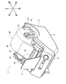
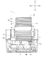
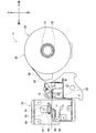
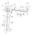
- FIG. 1 is an external perspective view of a label printer according to an embodiment. It is a perspective view of the label printer of the state which removed the upper cover. It is a side view of the label printer with the upper cover removed.
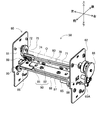
- FIG. 4 is a cross-sectional view taken along the line XX in FIG. 3. It is explanatory drawing which shows the label printer of the state which removed the upper cover and the sheet holder. It is an enlarged view showing a configuration in the vicinity of a determination recess in the label printer. It is explanatory drawing regarding the internal structure of a label printer. It is an external appearance perspective view (1) of a rotary cutter unit. It is an external appearance perspective view (2) of a rotary cutter unit.
- the label printer 1 is described with the lower left side in FIG. 1 as the front side, the upper right side in FIG. 1 as the rear side, the upper left side in FIG. 1 as the left side, and the lower right side as the right side.
- the label printer 1 includes an upper cover 2 and a main body housing 5.
- the upper cover 2 is made of a transparent resin, and is attached to be openable and closable around the rear upper edge of the main body housing 5.
- the main body housing 5 has a sheet holder storage portion 10 at a substantially central portion on the upper surface, and stores a platen roller 15, a thermal head 20, and a rotary cutter unit 50, which will be described later. Therefore, when the upper cover 2 is closed with respect to the main body housing 5, the upper cover 2 covers the upper side of the sheet holder storage portion 10, and the carry-out port 4 is formed between the front edge of the upper cover 2 and the main body housing 5.
- the carry-out port 4 is used when discharging the label sheet 36 drawn from the sheet holder 30 attached in the sheet holder storage unit 10. The sheet holder 30 and the label sheet 36 will be described in detail later.
- the main body casing 5 has a tray 3, a power button 6, and a power cord 7 on the outer surface of the main body casing 5.
- the tray 3 is formed in a plate shape with a transparent resin, and is erected so as to face a substantially central portion on the front end side of the upper cover 2.
- the label sheet 36 discharged from the carry-out port 4 is placed on the upper surface of the tray 3.
- the power button 6 is disposed on the surface of the main body housing 5 at a position corresponding to the front side of the tray 3, and is operated when switching on / off the power supply to the label printer 1.
- the power cord 7 is connected to the back side of the main body housing 5 (see FIG. 3), and connects the label printer 1 and an external power source.
- a connector portion is disposed on the back surface of the main body housing 5.
- the connector portion is used when the label printer 1 is connected to a computer device or the like so as to be able to perform data communication, and is a USB (Universal Serial). Bus)).
- the sheet holder storage portion 10 is formed as a concave portion having a predetermined shape on the upper surface of the main body housing 5, and includes a sheet holder 30 including a label sheet 36 that is a recording medium in the label printer 1. Is detachably accommodated. A positioning recess 10A and a determination recess 10B are formed on the bottom surface of the sheet holder storage portion 10 (see FIGS. 4 to 6).
- the positioning recess 10A is a recess formed on the bottom surface of the sheet holder storage portion 10 in a horizontally long rectangular shape in plan view, and has a predetermined depth (for example, about 1.5 to 3 mm) in the vertical direction.
- the width dimension (width dimension in the left-right direction) of the positioning recess 10A is formed to be substantially equal to the width dimension of each lower end edge of the sheet holder 30 described later. Therefore, the sheet holder 30 can be positioned at a predetermined position in the label printer 1 by arranging the sheet holder 30 in the positioning recess 10A.
- the discrimination recess 10B is formed in a rectangular shape in plan view having a long side in the front-rear direction within a predetermined range in the positioning recess 10A (the right inner wall surface side in the sheet holder storage portion 10).
- the recess is formed deeper than the positioning recess 10A by a predetermined depth (for example, about 1.5 to 3 mm).
- a sheet determination unit 31A constituting the sheet holder 30 is positioned in the determination recess 10B (see FIG. 4).
- the discriminating recess 10B has a sheet discriminating sensor 110 on its surface, and the sheet discriminating sensor 110 is configured by arranging five mechanical switches in a substantially L shape.
- the mechanical switch includes a plunger, a micro switch, and the like, and the upper end portion of each plunger protrudes from the bottom surface of the determination recess 10B to the vicinity of the bottom surface of the positioning recess 10A.
- the sheet discriminating portion 31A described above has a sensor hole that is formed according to the type of the label sheet 36 held by the sheet holder 30 (for example, the width dimension of the label sheet 36).
- the sheet determination sensor 110 is based on the presence or absence of the sensor hole of the sheet determination unit 31A for each mechanical switch.
- a detection signal can be output.
- the label printer 1 can detect the type of the label sheet 36 attached to the sheet holder 30 based on the detection signal from the sheet discrimination sensor 110.
- a holder support member 11 is erected on the right side portion of the sheet holder storage unit 10.
- the holder support member 11 has a first positioning groove portion 11 ⁇ / b> A and an engagement recess, and positions the sheet holder 30 at a predetermined position in the sheet holder storage portion 10.
- 11 A of 1st positioning groove parts are formed in the holder support member 11 in the front view substantially vertical U shape opened upward, and when the attachment part of the positioning holding member 31 which comprises the sheet holder 30 is inserted, The sheet holder 30 is positioned at a predetermined position of the sheet holder storage unit 10.
- the engagement recessed part is formed in the base end part of the sheet
- the sheet holder 30 is detachably accommodated in the sheet holder accommodating portion 10.
- an insertion port 12 and a placement portion 13 are formed in the front portion of the sheet holder storage portion 10.
- the insertion port 12 is an opening for inserting the label sheet 36 drawn from the sheet holder 30 in the sheet holder storage unit 10.
- the label sheet 36 inserted from the insertion port 12 is connected to the platen roller 15 and the thermal plate. It is conveyed toward the carry-out port 4 through the rotary cutter unit 50 between the heads 20.
- the mounting portion 13 extends substantially horizontally from the front edge of the sheet holder storage portion 10 toward the insertion port 12 and has a plurality of second positioning groove portions 13A.
- Each second positioning groove 13A has a width dimension (four types in the present embodiment) of the label sheet 36 that can be used in the label printer 1 at the corner of the rear end edge (sheet holder storage portion 10 side) of the placement portion 13. ) And is formed in a substantially L-shaped vertical section.
- the second positioning groove 13 ⁇ / b> A is formed so that a part of the guide member 32 constituting the sheet holder 30 can be fitted.
- a lever 14 is disposed on the left side portion of the sheet holder storage portion 10 so as to be able to rotate.
- the thermal head 20 is moved closer to and away from the platen roller 15 inside the main body casing 5 via an interlocking mechanism (not shown) inside the main body casing 5.
- control board C is arrange
- control board C includes a control circuit that drives and controls each mechanism unit according to a command from an external computer device or the like.
- the label printer 1 accommodates the platen roller 15, the thermal head 20, and the rotary cutter unit 50 in the main body housing 5.
- the platen roller 15 is rotatably supported above the conveyance path of the label sheet 36 on the downstream side in the conveyance direction of the label sheet 36 from the insertion port 12 (front side of the label printer 1). ing.
- the platen roller 15 is driven to rotate by driving a sheet conveyance motor 108 described later, and conveys the label sheet 36 at a predetermined sheet conveyance speed Vp.
- the thermal head 20 is disposed at a position facing the platen roller 15 via the conveyance path of the label sheet 36 (see FIG. 7), and in conjunction with the operation of the lever 14 as described above, Proximity to and separation from the roller 15.
- the thermal head 20 is a line-type thermal head having a plurality of heating elements 21 arranged in a row along the width direction of the label sheet 36 (see FIG. 20). Therefore, the label printer 1 controls the heat generation mode of each heat generating element 21 in units of lines constituting the print data, thereby performing printing in units of lines and printing in units of lines according to the conveyance of the label sheet 36. By executing sequentially, the desired print content can be printed on the label sheet 36.
- the rotary cutter unit 50 is disposed in the main body housing 5 on the downstream side of the platen roller 15 and the thermal head 20 in the conveyance direction of the label sheet 36 (see FIG. 7). Cut in a straight line.
- the configuration of the rotary cutter unit 50 will be described in detail later with reference to the drawings.
- the sheet holder 30 used in the label printer 1 according to the present embodiment includes a positioning and holding member 31, a guide member 32, a holder shaft member 33, and a roll sheet 35.
- the holder shaft member 33 rotatably holds the roll sheet 35. (See FIG. 4).
- the roll sheet 35 has an indefinite length label sheet 36 which is a recording medium according to the present embodiment, and a winding core 37, and the label sheet 36 is attached to the outer periphery of the cylindrical winding core 37. It is configured in a roll shape by being wound around.
- the label sheet 36 is formed in a tape shape having a predetermined width, and has a three-layer structure including a thermal paper 36A, an adhesive layer 36B, and a release paper 36C (see FIG. 3).
- the thermal paper 36A is formed as a long tape having self-coloring properties and has a printing surface on one side.
- the adhesive layer 36B is formed on the back side of the printing surface of the thermal paper 36A.
- the release paper 36C is stuck to the other surface side of the thermal paper 36A by the adhesive layer 36B. Therefore, by peeling the release paper 36C from the label sheet 36 and exposing the adhesive layer 36B, the label sheet 36 can be attached to a desired location.
- the label sheet 36 is wound around the core 37 so that the thermal paper 36 ⁇ / b> A is positioned on the core 37 side and the release paper 36 ⁇ / b> C is positioned on the outer peripheral side of the roll sheet 35.
- the recording medium according to the present embodiment is not limited to the indefinite length label sheet 36 but includes a die-cut label sheet.
- the die-cut label sheet is configured by adhering a plurality of die-cut labels made of thermal paper 36A and adhesive layer 36B formed in a predetermined shape to an indefinite length release paper 36C.
- the positioning holding member 31 constitutes the right side wall surface of the sheet holder 30 and has a sheet discriminating portion 31A, an attaching portion, and an elastic locking piece.
- the sheet discriminating portion 31 ⁇ / b> A is formed so as to extend from the lower end edge portion of the positioning holding member 31 in a substantially perpendicular inner direction.
- a sensor hole corresponding to the type of the label sheet 36 attached to the sheet holder 30 is formed in the sheet determination unit 31A.
- the mounting portion protrudes outward from the positioning and holding member 31 and is formed in a substantially rectangular shape with a vertically long cross section in the vertical direction.
- the attachment portion is fitted into the first positioning groove portion 11 ⁇ / b> A of the holder support member 11 and positions the sheet holder 30 at a predetermined position of the sheet holder storage portion 10. Further, the elastic locking piece protrudes outward from the lower end portion of the positioning holding member 31 and engages with an engagement recess formed in the base end portion of the holder support member 11, so that the sheet holder 30 is moved.
- the sheet holder storage unit 10 is detachably stored.
- the guide member 32 constitutes the left side wall surface of the seat holder 30 and has a front end portion extending to the front side of the main body housing 5.
- the front end portion is configured such that the lower surface thereof can be fitted into a second positioning groove portion 13A formed in the placement portion 13, and the lower end portion of the front end portion is fitted into the second positioning groove portion 13A so that the sheet holder can be accommodated.
- the sheet holder 30 is positioned at a predetermined position of the unit 10. Further, since the leading end extends to the vicinity of the insertion opening 12, the label sheet 36 is pulled out while the side edge of the label sheet 36 is brought into contact with the inner surface of the guide member 32, so that the label sheet 36 is inserted. Guidance with high accuracy.
- the holder shaft member 33 is horizontally disposed between the positioning holding member 31 and the guide member 32, and a cylindrical core 37 constituting the roll sheet 35 is inserted therethrough. Accordingly, the roll sheet 35 is rotatably held by the holder shaft member 33. As a result, in the sheet holder 30, the label sheet 36 is pulled out of the roll sheet 35 by rotating the roll sheet 35.
- the user opens the upper cover 2 and stores the sheet holder 30 having the desired type of label sheet 36 in a predetermined position of the sheet holder storage unit 10.
- the user inserts the mounting portion of the positioning holding member 31 into the first positioning groove portion 11 ⁇ / b> A of the holder supporting member 11, and engages the elastic locking piece of the positioning holding member 31 with the engaging recess of the holder supporting member 11.
- the user fits the lower end of the front end portion of the guide member 32 into the second positioning groove portion 13 ⁇ / b> A corresponding to the width dimension of the label sheet 36 constituting the sheet holder 30.
- the sheet holder 30 is positioned at a predetermined position in the sheet holder storage unit 10.
- the user rotates the lever 14 to separate the thermal head 20 from the platen roller 15.
- the user pulls out the label sheet 36 from the sheet holder 30 and inserts the label sheet 36 into the insertion opening 12 while abutting the edge of the label sheet 36 against the inner surface of the guide member 32.
- the user presses and urges the label sheet 36 inserted from the insertion port 12 toward the platen roller 15 by the line-type thermal head 20 by rotating the lever 14.
- the label printer 1 can be printed on the label sheet 36 by the thermal head 20.
- the label printer 1 rotates the platen roller 15 in accordance with a main control program described later (see FIG. 19), thereby controlling the heat generation mode of the thermal head 20 while conveying the label sheet 36. Printing is performed on the thermal paper 36A of the label sheet 36 based on the print data. Further, the label printer 1 cuts the label sheet 36 in the width direction and performs desired printing by controlling the rotary cutter unit 50 while carrying the label sheet 36 and printing the thermal head 20. Printed labels can be generated.
- FIG. 8 is an external perspective view when viewed from the upper right side on the front side of the rotary cutter unit 50
- FIG. 9 is an external perspective view when viewed from the lower left side on the rear side of the rotary cutter unit 50. It is.
- the rotary cutter unit 50 has a first flat blade 80 with respect to the unit frame 60, and a rotary blade member 70 rotatably disposed by a rotary shaft 75, A fixed blade member 85 having two flat blades 90 is attached, and by rotating the rotary blade member 70, the label sheet 36 being conveyed along the conveyance path in cooperation with the fixed blade member 85. Are cut linearly across the width direction.
- the unit frame 60 has a first side frame 61 and a second side frame 62 and constitutes an outer shell of the rotary cutter unit 50.
- the first side frame 61 constitutes the left side surface of the rotary cutter unit 50.
- the second side frame 62 constitutes the right side surface of the rotary cutter unit 50 and has a cutter motor 65 and a drive transmission mechanism 66.
- the cutter motor 65 is disposed below the fixed blade member 85 in the second side surface frame 62 and functions as a drive source for the rotary blade member 70 in the rotary cutter unit 50.
- the drive shaft 65 ⁇ / b> A of the cutter motor 65 passes through the second side frame 62 and protrudes outside the second side frame 62.
- the drive transmission mechanism 66 includes a gear train disposed between the rotary shaft 75 on the second side frame 62 side of the rotary blade member 70 and the drive shaft 65A of the cutter motor 65. Is transmitted to the rotary shaft 75 of the rotary blade member 70 via the drive shaft 65A. Accordingly, the rotary cutter unit 50 can rotate the rotary blade member 70 around the rotation shaft 75 as the cutter motor 65 rotates.
- the rotary blade member 70 is rotatably supported by a rotary shaft 75 formed above the conveyance path of the label sheet 36 between the first side frame 61 and the second side frame 62.
- the member 71 and the first flat blade 80 are used.
- the rotary blade holder member 71 includes a first bracket 72, a second bracket 73 (see FIGS. 11 and 12), and a flat blade mounting portion 74, and holds the first flat blade 80.
- the first bracket 72 is formed on the first side frame 61 side of the rotary blade holder member 71, and extends along the first side frame 61 from the first side frame 61 side edge of the flat blade mounting portion 74. It extends vertically.
- the first bracket 72 rotatably supports the rotary blade holder member 71 by cooperating with the rotary shaft 75 on the first side surface frame 61 side.
- the first bracket 72 is connected to the flat blade mounting portion 74 from the rotation axis O, which is the axis of the rotating shaft 75 (that is, the end of the flat blade mounting portion 74 on the first side frame 61 side).
- the dimension up to is a predetermined first dimension LA (see FIG. 11). Accordingly, when the rotary blade holder member 71 rotates about the rotation shaft 75, the end portion of the flat blade mounting portion 74 on the first side surface frame 61 side draws a first rotation locus SA having a radius of the first dimension LA ( (See FIG. 13).
- the 2nd bracket 73 (refer FIG. 11, FIG. 12) is formed in the 2nd side frame 62 side in the rotary blade holder member 71, and the 2nd side frame 62 side end of the flat blade attachment part 74 of flat form. From the edge, it extends vertically along the second side frame 62.
- the second bracket 73 rotatably supports the rotary blade holder member 71 by cooperating with the rotary shaft 75 on the second side frame 62 side.
- the rotation shaft 75 on the second side frame 62 side is located on the same axis as the rotation shaft 75 on the first side frame 61 side.
- the rotation axis O of the rotation shaft 75 is orthogonal to the conveyance direction of the label sheet 36 (in front of the label printer 1) and extends horizontally.
- the second bracket 73 extends from the rotation axis O to the connecting portion with the flat blade mounting portion 74 (that is, the end of the flat blade mounting portion 74 on the second side frame 62 side). Is formed to be a second dimension LB smaller than the first dimension LA (see FIG. 11). Therefore, when the rotary blade holder member 71 rotates about the rotation shaft 75, the end of the flat blade mounting portion 74 on the second side frame 62 side draws a second rotation locus SB having a radius of the second dimension LB ( (See FIG. 13). As described above, since the second dimension LB is smaller than the first dimension LA, the second rotation locus SB is a rotation locus having a smaller diameter than the first rotation locus SA.
- the flat blade mounting portion 74 is formed in a substantially rectangular plate shape that connects between the first bracket 72 and the second bracket 73 (see FIGS. 11 and 12).
- the first flat blade 80 is fixed at a predetermined position by a screw or the like.
- the flat blade mounting portion 74 has the first side frame 61 side edge spaced apart from the rotation axis O by the first dimension LA, and the second side frame 62 side edge is the rotation axis O. Rotate about the rotation axis O in a state separated from the second dimension LB.
- the flat blade mounting portion 74 forms a first inclination angle ⁇ with respect to the rotation axis O based on the difference between the first dimension LA and the second dimension LB with respect to the rotation axis O extending horizontally. (See FIG. 11).
- the first flat blade 80 functions as a rotary blade in the rotary blade member 70 and is attached to the flat blade attachment portion 74 of the rotary blade holder member 71 in a predetermined manner.
- the first flat blade 80 includes a first base portion 81 and a first blade edge portion 82.
- the first base portion 81 is formed in a substantially plate shape, and the first flat blade 80 is fixed to the flat blade mounting portion 74 with the first base portion 81.
- the first cutting edge 82 extends linearly on the edge side of the first base 81 and constitutes the cutting edge of the rotary blade.
- the first flat blade 80 has a predetermined second inclination angle ⁇ formed by the extending direction of the first cutting edge portion 82 and the direction of the edge of the substantially rectangular flat blade mounting portion 74.
- the flat blade mounting portion 74 is fixed.
- the end on the second bracket 73 side (hereinafter referred to as the second end 82B) of the first cutting edge 82 is the end of the first cutting edge 82. It protrudes from the end edge portion of the flat blade mounting portion 74 from the end portion on the first bracket 72 side (hereinafter referred to as the first end portion 82A).
- the first cutting edge portion 82 of the first flat blade 80 draws a rotation locus around the rotation shaft 75 as the rotary blade holder member 71 rotates.
- the first end portion 82A of the first cutting edge portion 82 draws a circumferential locus SE having the same diameter as the second end portion 82B with the rotation axis O as the center.
- the first cutting edge portion 82 is formed so as to linearly connect the first end portion 82A and the second end portion 82B, the first end portion 82A and the second end portion 82 in the first cutting edge portion 82 are formed.
- the portion between the end portions 82B (hereinafter, the intermediate portion 82C) is more than the rotation trajectory of the first end portion 82A and the second end portion 82B (that is, the circumferential trajectory SE) as the rotary blade holder member 71 rotates. On the inside, a rotation locus with the rotation axis O as the center is drawn.
- first flat blade 80 has a second flat blade 90 whose rotation trajectory drawn by the first blade edge portion 82 constitutes the fixed blade member 85 when the rotary blade holder member 71 rotates about the rotation axis O. Is attached to the flat blade attachment portion 74 so as to be close to or overlap the second blade edge portion 92.
- the fixed blade member 85 is disposed between the first side surface frame 61 and the second side surface frame 62 so as to be swingable downward from the conveyance path of the label sheet 36, and the fixed blade member 86, It consists of two flat blades 90.
- the fixed blade holder member 86 holds the second flat blade 90 functioning as a fixed blade so as to be swingable at a predetermined position, and has a fixed blade holding portion 87 and an extending portion 88.
- the fixed blade holding portion 87 is formed in a flat plate shape extending substantially in parallel with the rotation axis O at a predetermined interval, and holds the second flat blade 90 by fixing with a mounting screw or the like (see FIG. 8 to 10).
- the extension portion 88 is formed by horizontally extending the left and right end portions of the fixed blade holding portion 87 in the longitudinal direction, and the fixed blade holder member 86 can be moved closer to and away from the rotation locus of the rotary blade member 70.
- a part of the swing support mechanism 95 that swingably supports is configured.
- the extension portion 88 is loosely fitted into long holes formed at predetermined positions of the first side frame 61 and the second side frame 62.
- the swing support mechanism 95 loosely fits the extending portions 88 into the elongated holes of the first side frame 61 and the second side frame 62, respectively, and the first side frame 61, the fixed blade holding portion 87, and the second side frame. 62 and the fixed blade holding portion 87 are attached to the screw blade 96, and the fixed blade holding portion 87 is urged toward the rotary blade member 70 by the torsion spring 96.
- the second flat blade 90 functions as a fixed blade in the fixed blade member 85 and is fixed to the fixed blade holding portion 87.
- the second flat blade 90 includes a second base portion 91 and a second blade edge portion 92.
- the second base portion 91 is formed in a substantially plate shape, and the second flat blade 90 is fixed to the fixed blade holding portion 87 with the second base portion 91.
- the second cutting edge 92 extends linearly to the edge of the second base 91 and constitutes the cutting edge of the fixed blade.
- the rotary cutter unit 50 has a predetermined angle (hereinafter referred to as the angle between the width direction of the label sheet 36 perpendicular to the conveyance direction of the label sheet 36 and the horizontal direction of the second blade edge portion 92). It is arranged so as to have a fixed blade inclination angle ⁇ ).
- the cutting operation of the label sheet 36 by the rotary cutter unit 50 will be described in detail with reference to the drawings.
- the first flat blade 80 of the rotary blade member 70 is in an upright state with respect to the second flat blade 90 of the fixed blade member 85, and the first in the rotary blade member 70.
- the blade edge portion 82 is located at a position farthest from the second blade edge portion 92 in the fixed blade member 85.
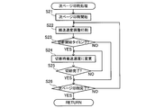
- the rotary cutter unit 50 controls the rotational drive of the cutter motor 65 according to the control program (see FIGS. 19 and 23) by the control unit 100, so that the end portion on the opposite side to the first cutting edge portion 82 is located.
- the rotary blade member 70 is rotated at the rotary blade rotation speed Vc so as to be in the front in the rotation direction, and the label sheet 36 on the transport path between the rotary blade member 70 and the fixed blade member 85 is cut in the transport state.
- the first bracket 72 is formed such that the dimension from the rotation axis O to the connection portion with the flat blade mounting portion 74 is the first dimension LA, and the second bracket 73 is the rotation axis.
- the dimension from the center O to the connecting portion with the flat blade mounting portion 74 is formed to be the second dimension LB (see FIG. 11).
- the flat blade mounting portion 74 has a first inclination angle ⁇ with respect to the rotation axis O so that the end on the second bracket 73 side is closer to the rotation axis O than the end on the first bracket 72 side. Tilt.
- first rotation locus SA having a radius of the first dimension LA
- second rotation locus SB having a radius of the second dimension LB is drawn inside the rotation locus SA (see FIG. 13).
- the 1st flat blade 80 which functions as a rotary blade makes the extending direction of the 1st blade edge
- the second end portion 82B on the second bracket 73 side has a larger projection amount with respect to the edge portion of the flat blade mounting portion 74 than the first end portion 82A on the first bracket 72 side. (See FIG. 12).
- the first flat blade 80 is attached so that the first blade edge portion 82 forms the second inclination angle ⁇ with respect to the edge portion of the flat blade attachment portion 74 inclined at the first inclination angle ⁇ with respect to the rotation axis O. Accordingly, when the rotary blade member 70 is rotated about the rotation axis O, the second end 82B of the first blade edge portion 82 is rotated by the second bracket 73 side end portion of the flat blade mounting portion 74. A rotational locus having a relatively large diameter is drawn on the outer side in the radial direction from the locus SB.
- the first end portion 82A of the first blade edge portion 82 is drawn by the first bracket 72 side end portion of the flat blade attachment portion 74.
- a rotation locus having a slightly larger diameter than the first rotation locus SA is drawn near the outside in the radial direction from SA. That is, when the rotary blade member 70 is rotated, in the first cutting edge portion 82 of the first flat blade 80, the rotation trajectory of the first end portion 82A and the rotation trajectory of the second end portion 82B are centered on the rotation axis O.
- a circumferential locus SE having substantially the same diameter is drawn (see FIG. 13).
- the first cutting edge portion 82 of the first flat blade 80 rotates at substantially the same distance from the rotation axis O over the entire area from the first bracket 72 side to the second bracket 73.
- the label printer 1 rotates the rotary blade member 70 while transporting the label sheet 36 along the transport path that is separated from the rotational axis O by a predetermined distance, whereby the first flat blade 80 has the first flat blade 80.
- the label sheet 36 can be cut substantially linearly by the entire cutting edge portion 82.
- the intermediate portion 82C rotates with a distance slightly smaller than the same distance relating to the first end portion 82A and the second end portion 82B.
- the amount of protrusion of the second end portion 82B of the first blade edge portion 82 with respect to the edge of the flat blade attachment portion 74 is increased, and the first rotation locus SA is set.
- the protruding amount of the first end portion 82A of the first cutting edge portion 82 with respect to the edge portion of the flat blade mounting portion 74 is made smaller than that of the first end portion 82A. Therefore, when the rotary blade member 70 is rotated, the timing of contacting the label sheet 36 conveyed along the conveyance path separated from the rotation axis O by a predetermined distance is the first end portion of the first blade edge portion 82.
- 82A differs from the second end 82B.
- the blade edges are labeled at the same timing as in the case of simply cutting a stationary label sheet 36 by providing a flat blade parallel to the rotation axis O.
- the rotary blade member 70 rotates by a predetermined amount
- the first end portion 82A of the first flat blade 80 cuts into the label sheet 36 conveyed on the conveyance path, and the rotary blade member is cut.
- the second end portion 82B of the first flat blade 80 is finally cut into the label sheet 36.
- the label sheet 36 has the rotary blade member 70 and the fixed blade member along the conveyance path from the second blade edge portion 92 side of the second flat blade 90 that is a fixed blade toward the second base portion 91 side. 85 is conveyed (see FIG. 10).
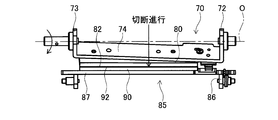
- the first cutting edge portion 82 of the first flat blade 80 that functions as a rotary blade. Near the first end portion 82A) is close to or overlaps the second cutting edge portion 92 of the second flat blade 90 that functions as a fixed blade. Therefore, the label printer 1 is transported along the transport path from the edge on the first side frame 61 side by controlling the rotary cutter unit 50 and causing the rotary blade member 70 and the fixed blade member 85 to cooperate. The cutting of the label sheet 36 being started is started.
- the portion where the first blade edge portion 82 and the second blade edge portion 92 overlap is the second bracket 73 side of the label sheet 36 (that is, the second side surface frame). 62 side).
- the label sheet 36 on the conveyance path is also continuously conveyed at a constant sheet conveyance speed Vp from the cutting start time by rotational driving of the platen roller 15 and the like according to a main control program (see FIG. 19) described later.
- the portion where the first blade edge portion 82 and the second blade edge portion 92 overlap is along the straight line that crosses the label sheet 36 in the width direction along the second bracket 73 side of the label sheet 36 (that is, the second side frame 62). Side) (see FIG. 15). That is, the label printer 1 can cut the label sheet 36 to the center in the width direction along a straight line that crosses the label sheet 36 in the width direction by further rotating the rotary blade member 70.
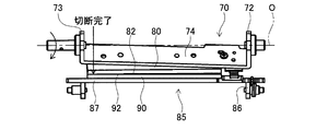
- the portion where the first blade edge portion 82 and the second blade edge portion 92 overlap is the second bracket 73 side (that is, the second side surface frame 62 side) of the label sheet 36. ) Reaches the end.
- the label sheet 36 on the conveyance path is also continuously conveyed at a constant sheet conveyance speed Vp from the cutting start time by rotational driving of the platen roller 15 and the like according to a main control program (see FIG. 19) described later. ing. Accordingly, the portion where the first blade edge portion 82 and the second blade edge portion 92 overlap each other across the label sheet 36 along a straight line that crosses the label sheet 36 in the width direction (see FIG. 16).
- the label printer 1 can cut the label sheet 36 in a straight line transverse to the width direction by rotating the rotary blade member 70, and thus the first flat blade 80 and the second flat blade 90.
- the rotary cutter unit 50 using the above, it is possible to realize a cutting function equivalent to a structure in which a spiral blade is provided on the outer periphery of a conventional cylindrical body.
- the control unit 100 is formed on the control board C described above, and plays a central role in controlling the entire label printer 1.
- the control unit 100 includes a CPU 101, a ROM 102, a RAM 103, a connection I / F 104, and an input / output interface 105.
- the CPU 101 is a so-called central processing unit, and controls each mechanism constituting the label printer 1 by executing a control program (see FIG. 19 and the like) stored in the ROM 102.
- the ROM 102 is a non-volatile storage device, and stores a control program, a data table, and the like necessary for controlling the label printer 1. Specifically, the ROM 102 stores control programs such as a main processing program (see FIG. 19) and a next page printing processing program (see FIG. 23) described later, and a data table such as a sheet conveyance speed determination table (see FIG. 18). Storing. The ROM 102 stores a label sheet type specifying table.
- the label sheet type specifying table is configured by associating various data based on the type of the label sheet 36 (the width dimension of the label sheet 36, etc.) with the pattern of the detection signal from the sheet discrimination sensor 110, and the sheet holder This is referred to when the type of the label sheet 36 in the sheet holder 30 attached to the storage unit 10 is specified.
- the RAM 103 is a storage device that temporarily stores calculation results and the like based on a control program by the CPU 101, and also functions as a print buffer.
- the connection I / F 104 is an interface for performing data communication between the label printer 1 and an external device (for example, a computer device) connected via the connector unit described above.
- print data used for printing in the label printer 1 is input from the computer device via the connection I / F 104 to the label printer 1 and temporarily stored in the RAM 103 functioning as a print buffer.
- control unit 100 is connected to the head drive circuit 106, the conveyance drive circuit 107, the cutting drive circuit 109, and the sheet determination sensor 110 via the input / output interface 105.
- the head drive circuit 106 is connected to the control unit 100 and the thermal head 20, and controls the heat generation mode of each heat generating element 21 constituting the thermal head 20 based on a control signal from the CPU 101.
- the conveyance drive circuit 107 is connected to the control unit 100 and the sheet conveyance motor 108, and performs drive control of the sheet conveyance motor 108 based on a control signal from the CPU 101.
- the sheet conveying motor 108 transmits the rotational driving force to the platen roller 15 via a drive transmission mechanism (not shown), and rotates the platen roller 15.
- the label printer 1 controls the driving of the sheet conveying motor 108 in accordance with a control signal from the CPU 101, whereby the sheet conveying speed Vp determined in the main processing program (that is, the first conveying speed Vp1 to the fifth conveying speed).
- the label sheet 36 can be conveyed in a predetermined direction by any one of Vp5.
- the cutting drive circuit 109 is connected to the control unit 100 and the cutter motor 65 of the rotary cutter unit 50, and performs drive control of the cutter motor 65 based on a control signal from the CPU 101.
- the cutter motor 65 transmits the driving force via the drive shaft 65A and the drive transmission mechanism 66 (see FIG. 10), thereby rotating the rotary blade member 70 to the rotational axis. Rotate around O. Therefore, the label printer 1 drives and controls the cutter motor 65 in accordance with a control signal from the CPU 101, thereby rotating the rotary blade member 70 at the rotary blade rotation speed Vc determined in the main processing program and being conveyed.
- the existing label sheet 36 can be cut.
- the sheet discrimination sensor 110 is disposed in the discrimination recess 10 ⁇ / b> B of the sheet holder storage unit 10, and is connected to the control unit 100 via the input / output interface 105.
- the sheet discrimination sensor 110 is composed of five mechanical switches, and detects the detection signal based on the presence or absence of the sensor hole of the sheet discrimination portion 31A in the sheet holder 30 in which the sheet holder storage portion 10 is mounted. Output to the CPU 101. Therefore, the label printer 1 determines the type of the label sheet 36 (for example, in the sheet holder 30 mounted in the sheet holder storage unit 10) based on the detection signal from the sheet discrimination sensor 110 and the label sheet type specifying table described above. The width dimension of the label sheet 36) can be specified.
- FIG. 19 is a flowchart of the main processing program according to the present embodiment.
- the main processing program is executed by the CPU 101 based on, for example, receiving a print instruction from a computer device (see FIG. 17).
- the label printer 1 has a line-type thermal head 20 in which a plurality of heating elements 21 (see FIG. 20) are arranged on the label sheet 36 conveyed by the platen roller 15. Printing is sequentially performed in units of print line data constituting the print data. As a result, print results based on the print line data are formed on the label sheet 36 in the order of the print data, and the print results based on the print data are printed on the label sheet 36.
- the CPU 101 executes a print data reading process.
- the CPU 101 reads print data created by a computer device or the like from the computer device or the like and stores it in the RAM 103. After storing the print data in the RAM 103, the CPU 101 shifts the process to S2.
- the print data according to the present embodiment is configured by arranging dots corresponding to the heat generating elements 21 constituting the thermal head 20 in a matrix, and indicates a print content desired by the user by a set of the dots. ing. Further, one side of the print data is configured by arranging the same number of dots as the number of heating elements 21 constituting the thermal head 20 in a row.
- the print data can be divided into a plurality of print line data.
- the print line data is composed of dots arranged in a line corresponding to all the heating elements 21 arranged in the thermal head 20, and means partial print data to be printed at the same time.
- the CPU 101 determines whether or not the print data read in the print data reading process (S1) indicates continuous printing.
- the label printer 1 can generate a print label in two modes, “continuous printing” and “single printing”. “Continuous printing” means that the print data includes print contents relating to a plurality of print labels, and the print labels are continuously printed and generated. “Individual printing” means that the printing data includes the printing content related to one printing label, and only one printing label is printed / generated.
- the CPU 101 executes a conveyance speed setting process based on the print data read in the print data reading process (S1).
- the CPU 101 performs printing based on the print data based on the print contents read in the print data reading process (S1) and the sheet conveyance speed determination table (see FIG. 18).
- the conveyance speed (sheet conveyance speed Vp) of the label sheet 36 is set.
- the sheet conveyance speed determination table referred to in the conveyance speed setting process (S3) will be described in detail with reference to FIG.
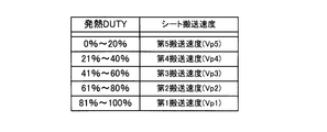
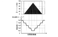
- the sheet conveyance speed determination table is configured by associating a predetermined sheet conveyance speed Vp with a numerical value range of heat generation DUTY.
- Heat generation DUTY indicates the ratio of heating elements 21 heated based on the print line data to all the heating elements 21 constituting the thermal head 20 when printing based on the print line data is performed.
- the sheet conveyance speed Vp includes five types of the first conveyance speed Vp1 to the fifth conveyance speed Vp5.
- the first conveyance speed Vp1 is the slowest, the second conveyance speed Vp2, and the third conveyance speed.
- the fast sheet conveyance speed Vp is shown in the order of the speed Vp3, the fourth conveyance speed Vp4, and the fifth conveyance speed Vp5. That is, in the sheet conveyance speed determination table, the larger the value of the heat generation DUTY, the slower the sheet conveyance speed Vp (for example, the first conveyance speed Vp1) is associated, and the smaller the value of the heat generation DUTY, the faster the sheet conveyance speed. Vp (fifth transport speed Vp5) is associated (see FIG. 18).
- the CPU 101 sets a sheet conveyance speed Vp for each unit period U based on a print line data group to be subjected to printing processing within a predetermined unit period U and a sheet conveyance speed determination table (FIG. 22, FIG. 24).
- the unit period U is a period defined based on the conveyance performance of the sheet conveyance motor 108, and in this embodiment, the conveyance speed of the label sheet 36 by the sheet conveyance motor 108 is “0” (that is, , The stop state) means a period required to increase to the maximum speed “fifth transport speed Vp5”.
- the CPU 101 specifies the sheet conveyance speed Vp related to each print line data based on the heat generation DUTY of each print line data to be printed within the unit period U and the sheet conveyance speed determination table. Then, the CPU 101 sets the slowest sheet conveyance speed Vp among the sheet conveyance speeds Vp of each print line data in the unit period U to the sheet conveyance speed Vp in the unit period U. The CPU 101 sets the sheet conveyance speed Vp for each unit period U by performing the above-described processing for all the unit periods U included in the print period required for printing the print data.
- the maximum number of heating elements 21 that can generate heat at a single heating timing is constant.
- the number is specified. Accordingly, when printing based on the print line data, if the number of heat generating elements 21 that generate heat exceeds the maximum number, the label printer 1 performs print line data by divided printing that performs printing by dividing the heat generation timing several times. It is necessary to perform printing based on. That is, when the value of the heat generation DUTY related to the print line data is large, the label printer 1 needs to generate a large number of heat generating elements 21 when printing the print line data, and performs printing by the above-described divided printing.
- the label printer 1 can perform printing based on the print line data on the label sheet 36 by performing heat generation control of the heat generating element 21 at one heat generation timing without performing the above-described divided printing.
- the heat generation control of each heat generating element 21 is performed in a plurality of times, so printing based on one print line data is completed compared to printing at a single heat generation timing.
- the required time to do is long.
- the range in which one print line data is printed on the label sheet 36 is required to be a fixed range regardless of whether the print is divided. is there. Therefore, when the heat generation DUTY is large and divided printing is performed, the label sheet 36 needs to be conveyed more slowly than when the heat generation DUTY is small.
- a sheet conveyance speed determination table in which a fast sheet conveyance speed Vp is associated with a small numerical range of heat generation DUTY, and a slow sheet conveyance speed Vp is associated with a large numerical range of heat generation DUTY.
- the label printer 1 can change the conveyance speed of the label sheet 36 to an appropriate sheet conveyance speed Vp corresponding to the contents of the print data at any time by executing the conveyance speed setting process (S3) using. Therefore, the print result can be provided quickly while maintaining the print quality.
- the label printer 1 performs printing based on the print data while conveying the label sheet 36 at the sheet conveyance speed Vp during continuous printing, and at the same time, the label sheet 36 is widened by the rotary cutter unit 50.
- the printed label is separated from the label sheet 36 by cutting in a straight line in the direction.
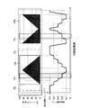
- the CPU 101 performs the printing on the label sheet 36 and the period during which the label sheet 36 is cut in parallel (hereinafter referred to as a cutting period) for each unit period U described above. Sets the conveyance speed of the label sheet 36 under different conditions. In other words, the CPU 101 sets the sheet conveyance speed Vp (hereinafter referred to as conveyance speed at cutting) within the cutting period based on the content of the print data to be printed within the cutting period and the sheet conveyance speed determination table.
- Vp sheet conveyance speed at cutting
- the CPU 101 prints data to be subjected to printing processing within the cutting period based on the printing data related to continuous printing read in the printing data reading processing (S1). (That is, the print line data group) is specified.
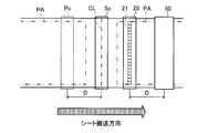
- the rotary cutter unit 50 is fixed at a position that is separated by a distance D downstream of the thermal head 20 in the transport direction (see FIGS. 7 and 20). ) The label sheet 36 printed by the thermal head 20 is cut linearly in the width direction. That is, when the cutting of the label sheet 36 and the printing on the label sheet 36 are performed in parallel, the thermal head 20 is positioned at a distance D away from the portion where the label sheet 36 is cut upstream in the transport direction. Is printed.
- the print data read in the print data reading process (S1) indicates continuous creation of a plurality of print labels, and has a print range PA corresponding to the contents of each print label. (See FIG. 20).
- a sheet cutting line CL is defined between the print ranges PA related to the print labels.
- the sheet cutting line CL indicates a reference for cutting by the rotary cutter unit 50 for separating one printed label from the label sheet 36, and extends linearly in the width direction of the label sheet 36.
- the CPU 101 can specify each sheet cutting line CL in the print data read in the print data reading process (S1), and can select the sheet cutting section Sc required for cutting the label sheet 36 based on each sheet cutting line CL. It can be specified.
- the rotary cutter unit 50 cuts at any time while conveying the label sheet 36 from one end side in the width direction of the label sheet 36 toward the other end side. The period which has a fixed time width from the cutting start in the width direction one end side to the completion of cutting in the other end side is shown.
- the CPU 101 prints the printing range at the time of cutting printed on the label sheet 36 by the rotary cutter unit 50 based on the specified sheet cutting line CL, the sheet cutting section Sc, and the distance D at the time of cutting based on the sheet cutting line CL.
- Pc can be specified. Specifically, the CPU 101 specifies a portion having a distance D on the upstream side in the conveyance direction with reference to the specified sheet cutting line CL, and within a certain period (a slightly longer period than the sheet cutting section Sc) before and after the specified portion.
- the printing range PA to be printed is specified as the cutting printing range Pc. That is, the printing range Pc during cutting indicates a portion of the printing range PA that is printed by the thermal head 20 when cutting along the sheet cutting line CL by the rotary cutter unit 50.
- the CPU 101 sets the cutting conveyance speed based on the contents of the print line data included in the cutting printing range Pc. Specifically, based on the heat generation DUTY of all the print line data included in the cutting print range Pc and the sheet conveyance speed determination table (see FIG. 18), all the print line data included in the cutting print range Pc. The sheet conveyance speed Vp is specified. Then, the CPU 101 sets “the slowest sheet conveying speed Vp among the sheet conveying speeds Vp in each print line data included in the cutting printing range Pc” as the cutting conveying speed.
- the conveyance speed at the time of cutting is the conveyance speed of the label sheet 36 within the cutting period, and shows a constant speed throughout the cutting period.
- the cutting conveyance speed is preferentially set for the cutting period regardless of the sheet conveyance speed Vp set for each unit period U (see FIG. 24). Then, the CPU 101 sets the sheet conveyance speed Vp (including the conveyance speed at the time of cutting) in all processes for creating a print label based on the print data read in the print data reading process (S1) by the conveyance speed setting process (S3). Then, the process proceeds to S4.
- the CPU 101 rotates based on the cutting conveyance speed set by the conveyance speed setting process (S3), the width dimension (sheet width H) of the label sheet 36 specified by the sheet discrimination sensor 110, and the like.
- the speed determination process is executed.
- the CPU 101 uses the rotational speed of the rotary blade member 70 when the label sheet 36 is linearly cut in the width direction using various conditions such as the cutting conveyance speed and the sheet width H.
- the rotary blade rotation speed Vc) is calculated and determined.
- the rotary blade rotation speed Vc is obtained by multiplying the product of the cutting conveyance speed set by the conveyance speed setting process (S3), the rotary blade rotation angle ⁇ , and the rotary blade rotation radius r by the label sheet. It is calculated by dividing by a product value of the sheet width H of 36 and the tangent value of the fixed blade inclination angle ⁇ .
- the rotary blade rotation speed Vc is expressed using the rotary blade rotation angle ⁇ , the rotary blade rotation radius r, and the time required for cutting t.
- the rotary blade rotation angle ⁇ means the rotation angle of the rotary blade member 70 required for cutting the label sheet 36 linearly in the width direction.
- the rotary blade rotation radius r means the rotation radius of the rotary blade member 70 (first cutting edge portion 82) having the rotation axis O as the rotation axis, and is substantially the same as the radius of the circumferential locus SE.
- the required cutting time t means the time required to cut the label sheet 36 linearly in the width direction.
- the rotary blade rotation speed Vc is expressed in a mode in which a value obtained by multiplying the rotary blade rotation angle ⁇ by the rotary blade rotation radius r is divided by the required cutting time t. That is, when attention is paid to the required cutting time t, the required cutting time t is expressed in a mode in which a value obtained by multiplying the rotary blade rotation angle ⁇ and the rotary blade rotation radius r is divided by the rotary blade rotation speed Vc.
- the transport amount of the label sheet 36 during the cutting period (the transport amount during cutting) will be considered from the viewpoint of transporting the label sheet 36.
- the label printer 1 sets the conveyance speed (sheet conveyance speed Vp) of the label sheet 36 during the cutting period to the conveyance speed during cutting. That is, in the cutting period (time required for cutting t), the label sheet 36 is transported at a constant transport speed based on the transport speed at the time of cutting. Accordingly, the cutting conveyance amount can be calculated by multiplying the cutting conveyance time (sheet conveyance speed Vp) by the required cutting time t.
- the cutting conveyance amount will be considered from the viewpoint of cutting the label sheet 36.
- the label sheet 36 cuts the label sheet 36 linearly in the width direction by the cooperation of the rotary blade member 70 and the fixed blade member 85 constituting the rotary cutter unit 50.
- the 2nd flat blade 90 which is a fixed blade is arrange
- the conveyance amount at the time of cutting is a value obtained by multiplying the conveyance speed at the time of cutting (sheet conveyance speed Vp) by the time required for cutting t, and the fixed blade inclination angle with respect to the sheet width H of the label sheet 36. It can be expressed as a value obtained by multiplying the tangent value of ⁇ .
- the required cutting time t is expressed in a mode in which a value obtained by multiplying the rotary blade rotation angle ⁇ and the rotary blade rotation radius r is divided by the rotary blade rotation speed Vc. It can be substituted as the required cutting time t multiplied by the transport speed Vp).
- the rotary blade rotation speed Vc is obtained by multiplying the product of the cutting conveyance speed set by the conveyance speed setting process (S3), the rotary blade rotation angle ⁇ , and the rotary blade rotation radius r by the label sheet 36. This is expressed as a value obtained by dividing the sheet width H by the multiplication value of the tangent value of the fixed blade inclination angle ⁇ .
- the rotary blade rotation angle ⁇ , the rotary blade rotation radius r, and the fixed blade inclination angle ⁇ are eigenvalues based on the apparatus configuration of the label printer 1 and are known numerical values. .
- the cutting conveyance speed sheet conveyance speed Vp
- the rotational speed determination process S4 is shifted to.
- the label printer 1 can specify the type of the label sheet 36 in the sheet holder 30 attached to the sheet holder storage unit 10 by the sheet discrimination sensor 110, the label sheet 36 to be cut by the rotary cutter unit 50.
- the sheet width H can also be specified based on the detection signal of the sheet discrimination sensor 110. Therefore, the CPU 101 divides the multiplication value of the cutting conveyance speed, the rotary blade rotation angle ⁇ , and the rotary blade rotation radius r by the multiplication value of the sheet width H of the label sheet 36 and the tangent value of the fixed blade inclination angle ⁇ . By doing so, the rotary blade rotation speed Vc can be calculated and determined. When the rotary blade rotational speed Vc is calculated and determined, and the rotational speed determination process (S4) ends, the CPU 101 proceeds to S5.
- the CPU 101 starts printing the first page related to the first print label in the print data. Specifically, the CPU 101 starts heat generation control for each heat generating element 21 of the thermal head 20 based on the print line data related to the first print label, and is set in the transport speed setting process (S3). Based on the sheet conveyance speed Vp, the conveyance control of the label sheet 36 is started (S5). After starting the heat generation control of the thermal head 20 and the conveyance control of the label sheet 36 regarding the first printed label, the CPU 101 proceeds to S6.
- the CPU 101 performs conveyance speed adjustment printing for the first print label. More specifically, the CPU 101 sets the print line data constituting the first print label in the print data as the print target in the order of the configuration in the print data, and based on the print line data related to the print target, Sequentially, the heating mode of each heating element 21 in the thermal head 20 is controlled. At the same time, the CPU 101 performs drive control of the sheet conveyance motor 108 based on the sheet conveyance speed Vp for each unit period U set by the conveyance speed setting process (S3), so that the sheet conveyance speed Vp for each unit period U. Is variably controlled (see FIGS. 22 and 24). Thereby, the label printer 1 can promptly provide the first print label while maintaining the print quality. When the printing of the first print label (that is, the first page printing) is completed (S7), the CPU 101 shifts the process to S8.
- the CPU 101 executes the next page printing process in order to generate the second and subsequent print labels. Specifically, the CPU 101 executes a next page print processing program (see FIG. 23), thereby performing print processing relating to the second and subsequent print labels, and in a predetermined case, in parallel with the print processing. Then, the label sheet 36 is cut along the sheet cutting line CL.
- next page print processing program will be described in detail with reference to FIG.
- the CPU 101 starts the next page printing for the next printing label (S21), and executes the conveyance speed adjustment printing (S22) for the next printing label. More specifically, as in the case of the first page printing, the CPU 101 sets the print line data constituting the next print label in the print data as the print target in the configuration order in the print data, and relates to the print target. Based on the print line data, the heat generation mode of each heat generating element 21 in the thermal head 20 is sequentially controlled.
- the CPU 101 performs drive control of the sheet conveyance motor 108 based on the sheet conveyance speed Vp for each unit period U set by the conveyance speed setting process (S3), so that the sheet conveyance speed Vp for each unit period U. Is variably controlled (see FIG. 24).
- the label printer 1 can quickly provide the next print label while maintaining the print quality. Thereafter, the CPU 101 shifts the process to S23.
- the CPU 101 determines whether or not the cutting start timing (that is, the start of the cutting period) has arrived based on the sheet cutting line CL in the print data. Specifically, the CPU 101 determines whether or not the cutting start timing has arrived based on the sheet cutting line CL in the print data and the sheet conveyance speed Vp. When the cutting start timing has arrived (S23: YES), the CPU 101 shifts the process to S24. When the cutting start timing has not yet arrived (S23: NO), the CPU 101 shifts the process to S26.
- the cutting start timing that is, the start of the cutting period
- the CPU 101 drives and controls the sheet conveyance motor 108, changes the sheet conveyance speed Vp to the conveyance speed at the time of cutting related to the sheet cutting line CL set by the conveyance speed setting process (S3), and the label sheet.
- the conveyance of 36 is continued (see FIG. 24).
- the CPU 101 drives and controls the cutter motor 65, and the rotary blade of the rotary cutter unit 50 at the rotary blade rotation speed Vc determined in the rotation speed determination process (S4).
- the rotation in the member 70 is started.
- the CPU 101 shifts the processing to S25.
- the CPU 101 determines whether the cutting of the label sheet 36 based on the sheet cutting line CL has been completed. Specifically, the CPU 101 performs the determination in S25 based on whether or not the cutting period related to the sheet cutting line CL has elapsed.
- the CPU 101 shifts the process to S26.
- the CPU 101 returns the process to S24, and is transporting the label sheet 36 at the cutting transport speed set in the transport speed setting process (S3).
- the cutting of the label sheet 36 is continued by rotating the rotary blade member 70 at the rotary blade rotational speed Vc determined in the rotational speed determination process (S4).
- the CPU 101 While the processing of S23 to S25 is being executed, the CPU 101 continues printing from the conveyance speed adjustment printing (S22), and sets the print line data constituting the next print label as the print target in the configuration order in the print data. Based on the print line data relating to the print target, the heat generation mode of each heat generating element 21 in the thermal head 20 is sequentially controlled. Also, when executing the processing of S23 to S25, the CPU 101 keeps the label constant at the cutting transport speed set in the transport speed setting process (S3), unlike the transport speed adjustment printing (S22). The sheet 36 is conveyed.
- the CPU 101 determines whether or not the next page printing is completed. The CPU 101 makes a determination in S26 based on whether or not the heat generation control of the thermal head 20 relating to all print line data relating to the next print label is completed. If the next page printing has been completed (S26: YES), the CPU 101 ends the next page printing process program and shifts the process to S9 of the main process program (see FIG. 19). When the next page printing related to the next printing label is not completed (S26: NO), the CPU 101 returns the process to S22 and continues the next page printing.
- the CPU 101 determines whether printing for all the print labels included in the print data read in the print data reading process (S1) has been completed. (S9). When printing related to all the print labels in the print data has been completed (S9: YES), the CPU 101 shifts the process to S13. If there is an unprocessed print label (S9: NO), the CPU 101 returns the process to the next page print process (S8), and executes the next page print process for the unprocessed print label.
- the CPU 101 first starts printing the print data related to the single printing (S10).
- the print data related to the single print has the print content related to one print label.
- the CPU 101 determines the sheet for each unit period U based on all print line data relating to the print label and the sheet conveyance speed determination table (see FIG. 18). The conveyance speed Vp is determined.
- the CPU 101 executes conveyance speed adjustment printing (S11). Also in this case, the CPU 101 sets the print line data constituting the print label relating to the single print as the print target in the order of the print data, and sequentially selects the print line data in the thermal head 20 based on the print line data related to the print target. The heat generation mode of the heat generating element 21 is controlled. At the same time, the CPU 101 variably controls the sheet conveyance speed Vp for each unit period U by performing drive control of the sheet conveyance motor 108 based on the set sheet conveyance speed Vp for each unit period U (see FIG. 22). ). As a result, the label printer 1 can quickly provide a print label for single printing while maintaining print quality. When the printing of the print label relating to the single printing is completed (S12), the CPU 101 shifts the process to S13.
- the CPU 101 sets the sheet conveying speed Vp to “fifth conveying speed Vp5” and starts conveying the label sheet 36 at the fifth conveying speed Vp5.
- the CPU 101 can quickly convey the sheet cutting line CL for separating the last print label from the label sheet 36 to the rotary cutter unit 50.
- the CPU 101 executes rear end cut processing for separating the last print label from the label sheet 36.
- the CPU 101 is the same as the rotation speed determination process (S4) based on the arrival of the cutting start timing related to the sheet cutting line CL related to the last print label specified based on the fifth transport speed Vp5.
- the rotary blade member 70 is rotated at the rotary blade rotation speed Vc calculated based on various conditions such as the fifth transport speed Vp5.
- the label printer 1 can quickly detach the last printed label from the label sheet 36, and thus can quickly provide a user-desired printed label.
- the CPU 101 proceeds to S15.
- the CPU 101 executes a print end process.
- the CPU 101 initializes the print buffer formed in the RAM 103, adjusts the position of each component device such as the rotary cutter unit 50, and the like.
- the position adjustment of each component device includes, for example, setting the rotary blade member 70 in the rotary cutter unit 50 to the initial position.
- the CPU 101 ends the main process program.
- the label printer 1 controls the heat generation mode of each heat generating element 21 of the thermal head 20 based on the print data acquired in the print data reading process (S1).
- a desired print label can be printed on the label sheet 36 conveyed at the sheet conveyance speed Vp.
- the label printer 1 includes a rotary cutter unit 50 having a rotary blade member 70, a fixed blade member 85, and a cutter motor 65 on the downstream side of the thermal head 20 in the conveyance direction of the label sheet 36. That is, the label printer 1 rotates the rotary blade member 70 around the rotation axis O at the rotary blade rotation speed Vc, thereby transporting the label sheet 36 and moving the label sheet 36 in the width direction. Can be cut linearly. That is, the label printer 1 can perform the printing based on the print data by the thermal head 20 and the cutting of the label sheet 36 by the rotary cutter unit 50 while conveying the label sheet 36 by the platen roller 15 or the like.
- the label printer 1 pre-reads the print data read by the print data reading process (S1) by the conveyance speed setting process (S3), and based on the heat generation DUTY of all the print line data constituting the print data.
- the sheet conveying speed Vp of the label sheet 36 for each unit period U is determined.
- the label printer 1 controls the drive of the sheet conveyance motor 108 so that the sheet conveyance speed Vp set in the conveyance speed setting process (S3) is performed when performing printing based on the print data.
- the conveyance speed of 36 is variably controlled. Therefore, the label printer 1 can perform printing by the thermal head 20 while transporting the label sheet 36 at the sheet transport speed Vp corresponding to the content of the print data to be printed, so that high quality is maintained.
- the label printer 1 has the sheet conveyance speed Vp of the label sheet 36 according to the conveyance performance of the sheet conveyance motor 108. Control can be performed with high accuracy.
- the period required to perform printing based on the print line data with high print quality is the ratio of the heating elements heated based on the print line data to all the heating elements constituting the thermal head (that is, The higher the heat generation DUTY), the longer it takes. Accordingly, the label printer 1 determines the sheet conveyance speed Vp of the label sheet 36 based on the level of the heat generation DUTY constituting the print data, so that the period during which the label sheet 36 is positioned on the thermal head 20 is appropriately set. Thus, a print label based on print data can be provided quickly while maintaining high quality.
- the label printer 1 sets the conveyance speed (conveyance speed at the time of cutting) of the label sheet 36 related to the cutting period in which the label sheet 36 is cut by the rotary cutter unit 50 to the cutting period.
- a constant speed is determined based on the print line data group printed therein. Therefore, according to the label printer 1, there is no change in the conveyance speed of the label sheet 36 during the cutting period. Thereby, the label printer 1 can surely cut the label sheet 36 linearly in the width direction by the rotary cutter unit 50.
- the label printer 1 specifies the sheet conveyance speed Vp based on each print line data to be printed within the cutting period when determining the conveyance speed during cutting in the conveyance speed setting process (S3), and cuts the sheet.
- the slowest sheet conveyance speed Vp is determined as a constant conveyance speed (that is, a conveyance speed during cutting) within the cutting period.
- the label printer 1 can ensure a sufficient period for maintaining high quality with respect to the printing of each print line data printed within the cutting period. Even in this case, the print label can be printed with high quality throughout the cutting period.
- the label printer 1 then cuts the label sheet 36 by the rotation speed determination process (S4), the sheet width H of the attached label sheet 36, the conveyance speed at the time of cutting set in the conveyance speed setting process (S3).
- the rotational speed (rotating blade rotational speed Vc) of the rotating blade member 70 is calculated and determined based on the rotating blade rotational angle ⁇ , the rotating blade rotational radius r, and the fixed blade tilt angle ⁇ required for the above. Accordingly, the label printer 1 has a rotating blade rotation speed Vc corresponding to the current state of the label printer 1 (for example, the sheet width H of the label sheet 36, the conveyance speed at the time of cutting the label sheet 36, etc.). Can be cut.
- the label printer 1 sets the rotary blade rotation speed Vc of the rotary blade member 70 even when conditions such as the conveyance speed at the time of cutting the label sheet 36 and the sheet width H of the label sheet 36 are changed.
- the label sheet 36 can be linearly cut across the width direction with higher accuracy.
- the label printer 1 can specify the type (sheet width H or the like) of the label sheet 36 mounted on the label printer 1 based on the detection signal from the sheet discrimination sensor 110. That is, the label printer 1 can automatically specify the sheet width H of the label sheet 36 used for calculating the rotary blade rotation speed Vc, and thus the rotary blade rotation speed Vc corresponding to the sheet width H of the label sheet 36. Can be calculated and adjusted. As a result, the label printer 1 can cut the label sheet 36 linearly across the width direction with higher accuracy.
- the present invention has been described above based on the embodiments. However, the present invention is not limited to the above-described embodiments, and various improvements and modifications can be made without departing from the spirit of the present invention.
- the width direction of the label sheet 36 can be adjusted.
- the fixed blade inclination angle ⁇ is formed between the second blade tips 92, the present invention is not limited to this mode.
- the fixed blade inclination angle ⁇ may be formed between the width direction of the label sheet 36 and the second blade edge portion 92 depending on the attachment state of the second flat blade 90 to the fixed blade holding portion 87 of the fixed blade member 85.
- the rotary cutter unit 50 is configured by a flat blade having a blade edge extending linearly, both of the fixed blade and the rotary blade, but is not limited to this aspect. That is, it is also possible to configure a rotary blade having a spiral blade edge on the outer peripheral surface of a cylindrical member and a fixed blade.
- the label printer 1 can be configured to perform the front end cutting process when printing the first printed label. That is, during the printing process of the first printed label, the label sheet 36 is linearly moved in the width direction by the rotary cutter unit 50 based on the sheet cutting line CL positioned in front of the first printed label. It is also possible to configure so as to be cut.
- a label printer is applied as a printing apparatus, and a label sheet 36 including thermal paper is applied as a recording medium.
- the present invention is not limited to this mode. That is, as long as the recording medium is long, regardless of the type of recording medium, the printing apparatus can print on the long recording medium and cut the recording medium with a rotary cutter unit. If so, the present invention can be applied to various printing apparatuses regardless of the label printer.
Landscapes
- Handling Of Sheets (AREA)
- Printers Characterized By Their Purpose (AREA)
- Accessory Devices And Overall Control Thereof (AREA)
- Electronic Switches (AREA)
Abstract
被記録媒体の搬送を行いつつ、印刷データに基づく印刷及び被記録媒体の切断を並行して実行可能な印刷装置に関し、搬送中の被記録媒体を直線状に切断し得る印刷装置を提供する。ラベルプリンタ(1)は、ラベルシート(36)を搬送しつつ、サーマルヘッド(20)による印刷と、回転刃部材(70)、固定刃部材(85)等を有するロータリーカッタユニット(50)によるラベルシート(36)の切断を並行して行い得る。CPU(101)は、印刷開始前に印刷データを先読みし、単位期間(U)毎のシート搬送速度(Vp)を設定すると共に、切断期間に対し、一定の切断時搬送速度を設定する(S3)。CPU(101)は、切断時搬送速度等の条件に基づいて、回転刃回転速度(Vc)を決定する(S4)。CPU(101)は、単位期間(U)毎にシート搬送速度(Vp)を可変させ、切断期間においては、切断時搬送速度でラベルシート(36)を搬送しつつ、回転刃回転速度(Vc)で回転刃部材(70)を回転させる。
Description
本発明は、所定の搬送方向に被記録媒体を搬送しつつ印刷を行い、被記録媒体の搬送と並行して、搬送方向と交わる方向に当該被記録媒体を切断する印刷装置に関する。
従来、印刷装置において、長尺状の媒体を所定の搬送方向に搬送しつつ、当該搬送方向に交わる方向に被記録媒体を切断する切断機構を有するものが知られている。
このような切断機構を備える印刷装置に関する発明として、特許文献1記載の発明が知られている。当該特許文献1記載の印刷装置は、長尺状の孔版原紙に所定の搬送方向に搬送しつつ、書き込みヘッドにより、順次、画像データに基づく穿孔画像を当該孔版原紙上に形成する。又、当該特許文献1記載の印刷装置は、固定刃と回転刃を有する原紙カッタ(所謂、ロータリーカッタ)を備えており、当該原紙カッタは、孔版原紙の搬送方向の直交方向に対する原紙カッタの傾斜角の正接が、原紙カッタの切断速度に対する孔版原紙の搬送速度の比と等しくなるように、装置本体に対して固定されている。従って、当該印刷装置は、穿孔画像が形成された孔版原紙を一定の搬送速度で搬送しつつ、当該原紙カッタを一定の切断速度で駆動することにより、搬送方向の直交方向に孔版原紙を切断し得る。
特許文献1記載の印刷装置では、孔版原紙に対する穿孔画像の形成と、原紙カッタによる孔版原紙の切断は、異なる時期に行われている。上述したように、両者は孔版原紙を搬送方向に搬送する点で共通しているため、同時期に行うことも可能である。即ち、画像の形成と、被記録媒体の切断を同時期に並行して行うことができれば、所望の印刷結果をユーザに提供する為の所要期間を短縮することができる。
ここで、印刷装置においては、印刷時における被記録媒体の搬送速度を、印刷データの内容に応じて可変する印刷装置も知られている。被記録媒体に対する印刷に要する時間は、印刷データにおける印刷を要する部分の多少に対応するため、当該印刷装置は、印刷データの内容に応じて、被記録媒体の搬送速度を可変することによって、印刷結果の品質を高く維持しつつ、当該印刷結果を迅速に提供し得る。
印刷時における被記録媒体の搬送速度を、印刷データの内容に応じて可変する印刷装置に対して、特許文献1記載の印刷装置に係る切断機構を適用した場合について考察する。上述したように、特許文献1記載の印刷装置においては、孔版原紙の搬送速度は、一定であり、原紙カッタの切断速度も一定の値に設定されている。又、特許文献1記載の印刷装置では、原紙カッタは、孔版原紙の搬送方向の直交方向に対する傾斜角が、切断速度と搬送速度に基づく条件を満たすように装置本体に対して固定されている。
従って、印刷時における被記録媒体の搬送速度が、印刷データの内容に応じて可変する場合、特許文献1における原紙カッタの傾斜角に係る条件を満たさない状況が頻繁に生じ得る。この結果、被記録媒体が搬送方向の直交方向から大きくずれて斜めに切断されてしまう場合がある。又、原紙カッタによる切断動作中に、被記録媒体の搬送速度が変更されてしまった場合、被記録媒体は、折れ線状に切断されてしまい、搬送方向の直交方向に直線状に切断することもできなくなってしまう。
又、特許文献1では、原紙カッタの搬送方向に直交する方向に対する傾斜角を調整しても良い旨が記載されている。しかしながら、被記録媒体の搬送速度が変更されると、その都度、装置本体に対する原紙カッタの傾斜角を調整する為に、装置本体に対する原紙カッタの取付状態を変更する作業を行わなければならず、利便性の悪いものとなってしまう。
本発明は、被記録媒体の搬送を行いつつ、印刷データに基づく印刷及び被記録媒体の切断を行い得る印刷装置に関し、印刷データの内容に基づき被記録媒体の搬送速度を可変としつつ、搬送中の被記録媒体を直線状に切断し得る印刷装置を提供する。
本発明の一側面に係る印刷装置は、被記録媒体に対する印刷の内容を示す印刷データを入力可能な印刷データ入力手段と、所定の搬送経路に沿った搬送方向に従って、前記被記録媒体を搬送する搬送手段と、前記印刷データ入力手段により入力された印刷データに基づいて、前記搬送手段により搬送方向に従って搬送される被記録媒体に順次印刷を行う印刷手段と、前記印刷データ入力手段により入力された印刷データを先読みし、当該印刷データの内容に基づいて、前記搬送手段による前記被記録媒体の搬送速度を決定する搬送速度決定手段と、前記搬送速度決定手段により決定された搬送速度に基づいて、前記搬送手段による前記被記録媒体の搬送速度を可変に制御する搬送制御手段と、前記搬送方向に交わる方向に延びる刃先を備えた固定刃と、回転軸を中心に回転可能に配設された回転刃と、前記回転刃を回転させる回転駆動手段を有し、前記印刷手段よりも搬送方向下流側に配設されると共に、前記回転軸を中心として、前記回転刃を回転させることにより、前記搬送経路を搬送される被記録媒体を、前記搬送方向に直交する幅方向に亘って直線的に切断するロータリーカッタと、前記搬送速度決定手段により決定された搬送速度に基づいて、前記回転駆動手段により前記回転刃を回転させる回転速度を決定する回転速度決定手段と、前記搬送速度決定手段により決定された搬送速度に従って、前記搬送手段により前記被記録媒体を搬送しつつ、前記印刷手段により前記印刷データに基づく印刷を行うと共に、前記回転速度決定手段により決定された回転速度に従って、前記回転刃を回転させることで、前記被記録媒体を直線的に切断する制御手段と、を有することを特徴とする。
当該印刷装置は、印刷データ入力手段と、搬送手段と、印刷手段と、搬送速度決定手段と、搬送制御手段と、ロータリーカッタと、回転速度決定手段と、制御手段とを有している。ロータリーカッタは、固定刃と、回転刃と、回転駆動手段を有し、前記印刷手段よりも搬送方向下流側において、前記回転軸を中心として、回転刃を回転させることにより、前記搬送経路を搬送される被記録媒体を、幅方向に亘って直線的に切断する。従って、当該印刷装置は、前記搬送手段により前記被記録媒体を搬送しつつ、前記印刷手段により前記印刷データに基づく印刷と、ロータリーカッタによる被記録媒体の直線的な切断を並行して行い得る。そして、当該印刷装置は、搬送速度決定手段により、印刷データ入力手段により入力された印刷データを先読みし、当該印刷データの内容に基づいて、前記被記録媒体の搬送速度を決定し、搬送制御手段により、当該搬送速度に基づいて、前記搬送手段による前記被記録媒体の搬送速度を可変に制御する。従って、当該印刷装置は、印刷データの内容に応じた搬送速度で被記録媒体を搬送しつつ、印刷手段による印刷を行うことができるので、高い品質を維持しつつ、迅速に、印刷データに基づく印刷結果を提供し得る。又、当該印刷装置は、回転速度決定手段により、前記回転刃の回転速度を、前記搬送速度決定手段により決定された搬送速度に基づいて決定する。即ち、当該印刷装置は、被記録媒体を搬送しつつ、印刷データに基づく印刷と、ロータリーカッタによる被記録媒体の切断を並行して行う際に、被記録媒体の搬送速度が可変制御された場合であっても、搬送速度に対応する回転速度をもって、回転刃を回転させることができるので、前記被記録媒体を幅方向に直線的に切断し得る。
そして、本発明の他の側面に係る印刷装置は、請求項1に記載の印刷装置であって、前記印刷手段は、前記搬送方向に直交する方向に列設された複数の発熱素子を有するサーマルヘッドを含み、前記印刷データに基づいて、各発熱素子に対する加熱態様を順次制御することにより、前記搬送手段により搬送方向に従って搬送される被記録媒体に印刷し、前記搬送速度決定手段は、前記印刷データに基づいて加熱される発熱素子が前記サーマルヘッドを構成する全ての発熱素子に対して占める割合に基づいて、前記搬送速度を決定することを特徴とする。
当該印刷装置において、印刷手段は、複数の発熱素子を有するサーマルヘッドを含み、印刷データに基づいて、各発熱素子に対する加熱態様を順次制御することにより、前記搬送手段により搬送方向に従って搬送される被記録媒体に、印刷データに基づく印刷を行う。そして、当該印刷装置は、搬送速度決定手段により、印刷データに基づいて加熱される発熱素子が前記サーマルヘッドを構成する全ての発熱素子に対して占める割合に基づいて、前記搬送速度を決定する。ここで、印刷データに基づく印刷を高い印刷品質で行う為に要する期間は、印刷データに基づいて加熱される発熱素子が前記サーマルヘッドを構成する全ての発熱素子に対して占める割合が高いほど、長く要する。従って、当該印刷装置は、印刷データに基づいて加熱される発熱素子が前記サーマルヘッドを構成する全ての発熱素子に対して占める割合に基づいて、被記録媒体の搬送速度を決定することで、被記録媒体がサーマルヘッド上に位置する期間を適切な期間とし、もって、高い品質を維持しつつ、迅速に、印刷データに基づく印刷結果を提供し得る。
又、本発明の他の側面に係る印刷装置は、請求項1又は請求項2に記載の印刷装置であって、前記搬送速度決定手段は、前記搬送手段の搬送性能に基づき特定される単位期間毎に、当該単位期間内に、前記印刷手段により前記被記録媒体へ印刷可能な印刷データの内容を先読みし、当該単位期間における被記録媒体の搬送速度を、先読みした前記単位期間に係る印刷データの内容に基づく一定の搬送速度に決定することを特徴とする。
当該印刷装置は、単位期間毎に、単位期間内に印刷される印刷データの先読みを行い、当該単位期間における被記録媒体の搬送速度を、先読みした単位期間に係る印刷データの内容に基づいて決定する。ここで、単位期間は、搬送手段の搬送性能に基づき特定される。従って、当該印刷装置は、搬送手段の搬送性能に応じて、被記録媒体の搬送速度の制御を高精度で行うことができ、もって、高い品質を維持しつつ、迅速に、印刷データに基づく印刷結果を提供し得る。
又、本発明の他の側面に係る印刷装置は、請求項3に記載の印刷装置であって、前記搬送速度決定手段は、前記ロータリーカッタにより前記被記録媒体が切断される切断期間における前記被記録媒体の搬送速度を、当該切断期間内に印刷される印刷データの内容に基づく一定の搬送速度を維持するように決定することを特徴とする。
当該印刷装置は、ロータリーカッタにより前記被記録媒体が切断される切断期間における前記被記録媒体の搬送速度を、当該切断期間内に印刷される印刷データの内容に基づく一定の搬送速度を維持するように決定する。従って、当該印刷装置によれば、切断期間内における被記録媒体の搬送速度に変化が生じることはないので、当該ロータリーカッタにより、被記録媒体を幅方向に亘って直線的に切断し得る。
又、本発明の他の側面に係る印刷装置は、請求項4に記載の印刷装置であって、前記搬送速度決定手段は、前記切断期間を構成する複数の単位期間毎に、当該単位期間内に、前記印刷手段により前記被記録媒体へ印刷可能な印刷データの内容を先読みし、先読みした各単位期間に係る印刷データの内容に基づいて、前記切断期間を構成する各単位期間における被記録媒体の搬送速度を夫々特定し、前記切断期間を構成する各単位期間に係る搬送速度の内で最も遅い搬送速度を、当該切断期間を通じて一定に維持される前記被記録媒体の搬送速度に決定することを特徴とする。
当該印刷装置は、前記切断期間を構成する複数の単位期間毎に、当該単位期間内に、前記被記録媒体へ印刷可能な印刷データの内容を先読みし、先読みした各単位期間に係る印刷データの内容に基づいて、前記切断期間を構成する各単位期間における被記録媒体の搬送速度を夫々特定し、前記切断期間を構成する各単位期間に係る搬送速度の内で最も遅い搬送速度を、当該切断期間を通じて一定に維持される前記被記録媒体の搬送速度に決定する。即ち、当該印刷装置は、切断期間内における一定の搬送速度を、切断期間を構成する各単位期間に関して特定された搬送速度の内、最も遅い搬送速度に設定することで、切断期間を構成する各単位期間における印刷を、何れも高い品質を維持して行い得る。又、切断期間における被記録媒体の搬送速度を一定に維持するので、当該印刷装置は、切断期間中に被記録媒体の搬送速度の変化が生じることはなく、ロータリーカッタにより、被記録媒体を幅方向に亘って直線的に切断し得る。
又、本発明の他の側面に係る印刷装置は、請求項1乃至請求項5の何れかに記載の印刷装置であって、前記回転速度決定手段は、前記搬送速度決定手段により決定された搬送速度と、前記搬送方向と直交する方向における前記被記録媒体の幅寸法と、前記被記録媒体を切断する為に要する前記回転刃の回転角度と、前記回転刃の刃先と前記回転軸との距離と、前記搬送方向と直交する方向と前記固定刃の刃先により構成される水平傾斜角と、に基づいて、前記回転速度を算出して決定することを特徴とする。
当該印刷装置は、搬送速度決定手段により、被記録媒体の搬送速度と、被記録媒体の幅寸法と、被記録媒体の切断に要する回転刃の回転角度と、回転刃の刃先と回転軸との距離と、固定刃の刃先による水平傾斜角とに基づいて、回転速度を算出して決定するので、当該印刷装置における現在の状況(被記録媒体の幅寸法、被記録媒体の搬送速度等)に対応する回転速度をもって、被記録媒体を切断し得る。従って、当該印刷装置は、被記録媒体の搬送速度や被記録媒体の幅寸法等の条件が変更された場合であっても、回転刃の回転速度を調整することで、より高い精度で、被記録媒体を幅方向に亘って直線的に切断し得る。
又、本発明の他の側面に係る印刷装置は、請求項6に記載の印刷装置であって、前記搬送方向に直交する方向における前記被記録媒体の幅寸法を検出する検出手段と、を有し、前記回転速度決定手段は、前記検出手段により検出された前記被記録媒体の幅寸法を用いて、前記回転刃の回転速度を算出して決定することを特徴とする。
当該印刷装置は、前記検出手段により検出された前記被記録媒体の幅寸法を用いて、前記回転刃の回転速度を算出して決定する。従って、当該印刷装置は、被記録媒体の幅寸法が変更された場合であっても、自動的に、被記録媒体の幅寸法に対応する回転刃の回転速度に調整することができ、より高い精度で、被記録媒体を幅方向に亘って直線的に切断し得る。
又、本発明の他の側面に係る印刷装置は、請求項1乃至請求項7の何れかに記載の印刷装置であって、前記被記録媒体である長尺状のロールシートを、巻回された状態で回転可能に保持するロールシートホルダを、着脱可能に構成され、前記搬送手段は、前記ロールシートホルダからロールシートを引き出しつつ、前記搬送経路上を前記搬送方向へ搬送し、前記印刷手段は、前記印刷データ入力手段により入力された印刷データに基づいて、前記搬送手段により搬送方向に従って搬送されるロールシートに順次印刷を行い、前記ロータリーカッタは、前記印刷手段によって、前記印刷データに基づく印刷が施されたロールシートを、所望の長さに切断することにより、印刷ラベルを作成することを特徴とする。
当該印刷装置は、前記搬送手段により前記ロールシートを搬送経路に沿って搬送しつつ、前記印刷手段により前記印刷データに基づくラベル印刷と、ロータリーカッタによるロールシートの幅方向への直線的な切断を並行して行い得る。そして、当該印刷装置は、ロールシートを搬送しつつ、印刷データに基づくラベル印刷と、ロータリーカッタによるロールシートの切断を並行して行う際に、ロールシートの搬送速度が可変制御された場合であっても、搬送速度に対応する回転速度をもって、回転刃を回転させることができるので、前記ロールシートを幅方向に直線的に切断し、所望の印刷が施された印刷ラベルを提供し得る。
以下、本発明に係る印刷装置を、ラベルプリンタ1に具体化した実施形態について、図面を参照しつつ詳細に説明する。尚、以下の説明においては、ラベルプリンタ1は、図1における左下側を前側とし、図1における右上側を後側とし、図1における左上側を左側とし、右下側を右側として説明する。
図1に示すように、本実施形態に係るラベルプリンタ1は、上部カバー2と、本体筐体5とを有して構成されている。上部カバー2は、透明樹脂により形成されており、本体筐体5の後側上端縁部を軸として、開閉自在に取り付けられている。本体筐体5は、上面略中央部にシートホルダ収納部10を有しており、後述するプラテンローラ15、サーマルヘッド20、ロータリーカッタユニット50を収容している。従って、上部カバー2は、本体筐体5に対して閉じた場合、シートホルダ収納部10の上側を覆い、上部カバー2の前端縁と、本体筐体5の間に搬出口4を形成する。搬出口4は、シートホルダ収納部10内に取り付けられたシートホルダ30から引き出されたラベルシート36を排出する際に用いられる。シートホルダ30及びラベルシート36については、後に詳細に説明する。
又、本体筐体5は、トレイ3、電源ボタン6、電源コード7を、当該本体筐体5の外表面に有している。トレイ3は、透明樹脂により板状に形成されており、上部カバー2の前端側における略中央部に対向するように立設されている。当該トレイ3には、搬出口4から排出されたラベルシート36が、トレイ3上面に載置される。電源ボタン6は、トレイ3の前側にあたる位置において、本体筐体5表面に配設されており、ラベルプリンタ1に対する電力供給のオン・オフを切り替える際に操作される。そして、電源コード7は、本体筐体5の背面側に接続されており(図3参照)、当該ラベルプリンタ1と外部電源とを接続する。
尚、本体筐体5の背面部には、コネクタ部が配設されており、当該コネクタ部は、ラベルプリンタ1を、コンピュータ装置等とデータ通信可能に接続する際に用いられ、USB(Universal Serial Bus)等から構成されている。
図2~図6に示すように、シートホルダ収納部10は、本体筐体5上面に所定形状の凹部として形成されており、ラベルプリンタ1における被記録媒体であるラベルシート36を含むシートホルダ30を着脱可能に収容する。そして、シートホルダ収納部10の底面には、位置決め凹部10Aと、判別凹部10Bが形成されている(図4~図6参照)。
位置決め凹部10Aは、シートホルダ収納部10の底面部を、平面視横長四角形状に形成された凹部であって、垂直方向に所定深さ(例えば約1.5~3mm)を有している。当該位置決め凹部10Aの幅寸法(左右方向の幅寸法)は、後述するシートホルダ30の各下端縁部の幅寸法にほぼ等しくなるように形成されている。従って、シートホルダ30を、当該位置決め凹部10A内に配置することで、シートホルダ30をラベルプリンタ1における所定位置に位置決めし得る。
図4~図6に示すように、判別凹部10Bは、位置決め凹部10Aにおける所定範囲(シートホルダ収納部10における右側の内壁面側)を、前後方向に長辺を有する平面視長方形状に形成された凹部であって、位置決め凹部10Aよりも更に所定深さ(例えば約1.5~3mm)だけ深く形成されている。後述するシートホルダ30を位置決め凹部10Aに位置決めすると、当該シートホルダ30を構成するシート判別部31Aが、判別凹部10B内に位置する(図4参照)。
当該判別凹部10Bは、その表面にシート判別センサ110を有しており、当該シート判別センサ110は、5個の機械式スイッチを略L字状に配設して構成されている。当該機械式スイッチは、プランジャーとマイクロスイッチ等から構成されており、各プランジャーの上端部は、判別凹部10Bの底面から位置決め凹部10Aの底面近傍まで突出している。ここで、上述したシート判別部31Aは、当該シートホルダ30に保持されているラベルシート36の種類(例えば、ラベルシート36の幅寸法)に応じて穿設されたセンサ孔を有している。従って、シートホルダ30を位置決め凹部10A内に位置決めし、シート判別部31Aが判別凹部10B内に位置した場合、シート判別センサ110は、各機械式スイッチに対するシート判別部31Aのセンサ孔の有無に基づく検出信号を出力し得る。この結果、当該ラベルプリンタ1は、シート判別センサ110からの検出信号に基づいて、シートホルダ30に装着されたラベルシート36の種類を検出し得る。
そして、シートホルダ収納部10の右側部分には、ホルダ支持部材11が立設されている。当該ホルダ支持部材11は、第1位置決め溝部11Aと、係合凹部を有しており、シートホルダ30をシートホルダ収納部10の所定位置に位置決めする。第1位置決め溝部11Aは、ホルダ支持部材11において、上方に開口する正面視略縦長コの字状に形成されており、シートホルダ30を構成する位置決め保持部材31の取付部がはめ込まれることにより、シートホルダ30をシートホルダ収納部10の所定位置に位置決めする。そして、係合凹部は、ホルダ支持部材11におけるシートホルダ収納部10側面の基端部に形成されており、位置決め保持部材31下端部に突設された弾性係止片と係合することで、シートホルダ30をシートホルダ収納部10に対して着脱可能に収容している。
そして、シートホルダ収納部10の前側部分には、挿入口12及び載置部13が形成されている。挿入口12は、シートホルダ収納部10内のシートホルダ30から引き出されたラベルシート36を挿入する為の開口部であり、当該挿入口12から挿入されたラベルシート36は、プラテンローラ15とサーマルヘッド20の間、続いてロータリーカッタユニット50を介して、搬出口4へ向かって搬送される。
載置部13は、シートホルダ収納部10の前側端縁から挿入口12に向かって略水平に延出されており、複数の第2位置決め溝部13Aを有している。各第2位置決め溝部13Aは、載置部13の後端縁(シートホルダ収納部10側)の角部において、当該ラベルプリンタ1で使用可能なラベルシート36の幅寸法(本実施形態では4種類)に対応する位置に形成されており、鉛直断面略L字状に形成されている。そして、第2位置決め溝部13Aは、シートホルダ30を構成するガイド部材32の一部を嵌め込むことできるように形成されている。
又、シートホルダ収納部10の左側部分には、レバー14が回動操作可能に配設されている。レバー14は、その回動操作が行われると、本体筐体5内部の連動機構(図示せず)を介して、本体筐体5内部で、サーマルヘッド20をプラテンローラ15に対して近接・離間させる。従って、レバー14を操作し、サーマルヘッド20をプラテンローラ15に近接する方向へ移動させると、サーマルヘッド20は、ラベルシート36をプラテンローラ15に押圧付勢する。即ち、当該ラベルプリンタ1は、レバー14を操作することにより、ラベルシート36に対する印刷が可能な状態となる。
尚、図4に示すように、シートホルダ収納部10の下側には、制御基板Cが配設されている。当該制御基板Cは、外部のコンピュータ装置等からの指令により各機構部を駆動制御する制御回路等を有している。
上述したように、本実施形態に係るラベルプリンタ1は、プラテンローラ15、サーマルヘッド20、ロータリーカッタユニット50を、本体筐体5内部に収容している。図7に示すように、プラテンローラ15は、挿入口12よりもラベルシート36の搬送方向下流側(ラベルプリンタ1の前方側)において、ラベルシート36の搬送経路の上方に回転自在に軸支されている。当該プラテンローラ15は、後述するシート搬送モータ108の駆動により回転駆動し、ラベルシート36を所定のシート搬送速度Vpで搬送する。
そして、サーマルヘッド20は、ラベルシート36の搬送経路を介して、プラテンローラ15と対向する位置に配設されており(図7参照)、上述したようにレバー14の操作に連動して、プラテンローラ15に対して近接・離間する。当該サーマルヘッド20は、ラベルシート36の幅方向に沿って、複数の発熱素子21を列設して有するライン型のサーマルヘッドである(図20参照)。従って、当該ラベルプリンタ1は、印刷データを構成するライン単位で、各発熱素子21の発熱態様を制御することで、ライン単位で印刷し、ラベルシート36の搬送に応じて、ライン単位の印刷を順次実行していくことにより、所望の印刷内容をラベルシート36に印刷し得る。
ロータリーカッタユニット50は、本体筐体5内部において、プラテンローラ15、サーマルヘッド20よりも、ラベルシート36の搬送方向下流側に配設されており(図7参照)、ラベルシート36を幅方向に亘って直線状に切断する。ロータリーカッタユニット50の構成については、後に図面を参照しつつ詳細に説明する。
続いて、本実施形態に係るラベルプリンタ1で使用されるシートホルダ30について、図面を参照しつつ詳細に説明する。本実施形態に係るシートホルダ30は、位置決め保持部材31と、ガイド部材32と、ホルダ軸部材33と、ロールシート35により構成されており、ホルダ軸部材33により、ロールシート35を回転可能に保持している(図4参照)。
ここで、ロールシート35は、本実施形態に係る被記録媒体である無定長のラベルシート36と、巻芯37を有しており、当該ラベルシート36を、円筒状の巻芯37の外周に巻回することにより、ロール状に構成されている。
ラベルシート36は、所定幅のテープ状に形成されており、感熱紙36A、粘着層36B、剥離紙36Cにより3層構造をなしている(図3参照)。感熱紙36Aは、自己発色性を有する長尺状のテープとして形成されており、一面に印刷面を有している。粘着層36Bは、感熱紙36Aにおける印刷面の裏面側に形成されている。そして、剥離紙36Cは、粘着層36Bによって、感熱紙36Aの他面側に貼着されている。従って、ラベルシート36から剥離紙36Cを剥離し、粘着層36Bを露出することによって、ラベルシート36は、所望の箇所に貼着することが可能となる。そして、ロールシート35において、ラベルシート36は、巻芯37を中心として、巻芯37側に感熱紙36A、ロールシート35の外周側に剥離紙36Cが位置するように巻回されている。尚、本実施形態に係る被記録媒体は、無定長のラベルシート36に限定されるものではなく、ダイカットラベルシートを含む。当該ダイカットラベルシートは、無定長の剥離紙36Cに対して、所定形状に形成された感熱紙36A及び粘着層36Bからなるダイカットラベルを、複数貼着して構成される。
位置決め保持部材31は、シートホルダ30の右側壁面を構成し、シート判別部31Aと、取付部と、弾性係止片を有している。シート判別部31Aは、位置決め保持部材31の下端縁部から略直角内側方向に延出して形成されている。シート判別部31Aには、当該シートホルダ30に装着されているラベルシート36の種類に対応するセンサ孔が形成されている。そして、取付部は、位置決め保持部材31の外側方向に突設され、上下方向に縦長の断面略矩形状に形成されている。当該取付部は、ホルダ支持部材11の第1位置決め溝部11Aに嵌合し、シートホルダ30をシートホルダ収納部10の所定位置に位置決めする。又、弾性係止片は、位置決め保持部材31下端部に外側方向に突設されており、ホルダ支持部材11の基端部に形成された係合凹部と係合することで、シートホルダ30をシートホルダ収納部10に対して着脱可能に収容している。
ガイド部材32は、シートホルダ30の左側壁面を構成し、本体筐体5の前方側に延出した先端部を有している。当該先端部は、その下面を載置部13に形成された第2位置決め溝部13Aに嵌め込み可能に構成されており、先端部の下端部を第2位置決め溝部13Aに嵌め込むことで、シートホルダ収納部10の所定位置に、シートホルダ30を位置決めする。又、先端部は、挿入口12近傍まで延出されているので、ラベルシート36の側端縁部をガイド部材32の内側面に当接させつつ、引き出すことで、ラベルシート36を挿入口12へ精度良く案内する。
ホルダ軸部材33は、位置決め保持部材31とガイド部材32との間に、水平に配設されており、ロールシート35を構成する円筒状の巻芯37を挿通している。従って、当該ロールシート35は、ホルダ軸部材33により回転可能に保持される。これにより、当該シートホルダ30において、ラベルシート36は、ロールシート35を回転させることにより、ロールシート35から引き出される。
次に、ラベルプリンタ1における印刷準備動作について説明する。ユーザは、上部カバー2を開き、所望の種類のラベルシート36を有するシートホルダ30を、シートホルダ収納部10の所定位置に収容する。この時、ユーザは、位置決め保持部材31の取付部を、ホルダ支持部材11の第1位置決め溝部11Aに嵌入させ、位置決め保持部材31の弾性係止片を、ホルダ支持部材11の係合凹部と係合させる。更に、ユーザは、ガイド部材32の先端部の下端を、当該シートホルダ30を構成するラベルシート36の幅寸法に対応する第2位置決め溝部13Aに嵌入させる。これにより、シートホルダ30は、シートホルダ収納部10における所定位置に位置決めされる。
そして、シートホルダ30をシートホルダ収納部10内に取り付けた後、ユーザは、レバー14を回動させて、サーマルヘッド20を、プラテンローラ15から離間させる。この状態で、ユーザは、ラベルシート36をシートホルダ30から引き出し、ラベルシート36の端縁部をガイド部材32の内側面に当接させつつ、挿入口12内に挿入する。その後、ユーザは、レバー14を回動させることにより、挿入口12から挿入されたラベルシート36を、ライン型のサーマルヘッド20によってプラテンローラ15へ押圧・付勢する。これにより、当該ラベルプリンタ1は、サーマルヘッド20によって、ラベルシート36に対して印刷可能な状態となる。
その後、当該ラベルプリンタ1は、後述するメイン制御プログラム(図19参照)に従って、プラテンローラ15を回転駆動することで、ラベルシート36を搬送しつつ、サーマルヘッド20の発熱態様を制御することにより、ラベルシート36の感熱紙36Aに対して、印刷データに基づく印刷を行う。又、当該ラベルプリンタ1は、ラベルシート36の搬送及びサーマルヘッド20の印刷を行いつつ、ロータリーカッタユニット50を駆動制御することで、ラベルシート36を幅方向に切断し、所望の印刷が施された印刷ラベルを生成し得る。
次に、本実施形態に係るラベルプリンタ1に係るロータリーカッタユニット50について、図面を参照しつつ詳細に説明する。尚、図8は、ロータリーカッタユニット50の前側において、右上方から見た場合の外観斜視図であり、図9は、ロータリーカッタユニット50の後側において、左下方から見た場合の外観斜視図である。
図8、図9に示すように、ロータリーカッタユニット50は、ユニットフレーム60に対して、第1平刃80を有し、回転軸75によって回転可能に配設された回転刃部材70と、第2平刃90を有する固定刃部材85を取り付けて構成されており、回転刃部材70を回転させることにより、固定刃部材85と協働して、搬送経路に沿って搬送されているラベルシート36を、幅方向に亘って直線状に切断する。
ユニットフレーム60は、第1側面フレーム61と、第2側面フレーム62を有しており、ロータリーカッタユニット50の外殻を構成する。第1側面フレーム61は、ロータリーカッタユニット50の左側面を構成する。第2側面フレーム62は、ロータリーカッタユニット50の右側面を構成し、カッターモータ65と、駆動伝達機構66を有している。
カッターモータ65は、第2側面フレーム62において、固定刃部材85の下方に配設されており、ロータリーカッタユニット50における回転刃部材70の駆動源として機能する。当該カッターモータ65の駆動軸65Aは、第2側面フレーム62を貫通して、第2側面フレーム62の外側に突出している。
そして、駆動伝達機構66は、回転刃部材70における第2側面フレーム62側の回転軸75と、カッターモータ65の駆動軸65Aの間に配設されたギヤ列により構成されており、カッターモータ65の駆動力を、駆動軸65Aを介して、回転刃部材70の回転軸75に伝達する。従って、当該ロータリーカッタユニット50は、カッターモータ65の回転駆動に伴って、回転刃部材70を回転軸75を中心に回転させ得る。
回転刃部材70は、第1側面フレーム61と第2側面フレーム62との間において、ラベルシート36の搬送経路よりも上方に形成された回転軸75によって回転可能に支持されており、回転刃ホルダ部材71と、第1平刃80により構成されている。
回転刃ホルダ部材71は、第1ブラケット72と、第2ブラケット73(図11、図12参照)と、平刃取付部74により構成されており、第1平刃80を保持している。第1ブラケット72は、回転刃ホルダ部材71における第1側面フレーム61側に形成されており、平板状の平刃取付部74の第1側面フレーム61側端縁から、第1側面フレーム61に沿って鉛直に延設されている。当該第1ブラケット72は、第1側面フレーム61側の回転軸75と協働することによって、回転刃ホルダ部材71を回転自在に軸支している。
又、当該第1ブラケット72は、回転軸75の軸心である回転軸心Oから平刃取付部74との接続部分(即ち、平刃取付部74における第1側面フレーム61側の端部)までの寸法が所定の第1寸法LAとなるように形成されている(図11参照)。従って、回転刃ホルダ部材71が回転軸75を中心に回転すると、平刃取付部74の第1側面フレーム61側の端部は、半径を第1寸法LAとする第1回転軌跡SAを描く(図13参照)。
そして、第2ブラケット73(図11、図12参照)は、回転刃ホルダ部材71における第2側面フレーム62側に形成されており、平板状の平刃取付部74の第2側面フレーム62側端縁から、第2側面フレーム62に沿って鉛直に延設されている。当該第2ブラケット73は、第2側面フレーム62側の回転軸75と協働することによって、回転刃ホルダ部材71を回転自在に軸支している。
尚、第2側面フレーム62側の回転軸75は、第1側面フレーム61側の回転軸75と同一軸芯上に位置している。そして、当該回転軸75の回転軸心Oは、ラベルシート36の搬送方向(ラベルプリンタ1の前方)に対して直交し、且つ、水平に延びている。
又、第2ブラケット73(図11、図12参照)は、回転軸心Oから平刃取付部74との接続部分(即ち、平刃取付部74における第2側面フレーム62側の端部)までの寸法が、前記第1寸法LAよりも小さな第2寸法LBとなるように形成されている(図11参照)。従って、回転刃ホルダ部材71が回転軸75を中心に回転すると、平刃取付部74の第2側面フレーム62側の端部は、半径を第2寸法LBとする第2回転軌跡SBを描く(図13参照)。上述したように、第2寸法LBは、第1寸法LAよりも小さいので、第2回転軌跡SBは、第1回転軌跡SAよりも小径の回転軌跡となる。
平刃取付部74は、第1ブラケット72と第2ブラケット73(図11、図12参照)との間を接続する略長方形状をなす平板状に形成されており、当該平刃取付部74には、第1平刃80がネジ等により所定位置に固定される。上述したように、平刃取付部74は、第1側面フレーム61側の端縁が、回転軸心Oから第1寸法LA離間し、第2側面フレーム62側の端縁が、回転軸心Oから第2寸法LB離間した状態で、回転軸心Oを中心に回転する。そして、当該平刃取付部74は、水平に延びる回転軸心Oに対する第1寸法LAと、第2寸法LBとの差に基づいて、回転軸心Oに対して、第1傾斜角αを為す(図11参照)。
第1平刃80は、回転刃部材70における回転刃として機能し、回転刃ホルダ部材71の平刃取付部74に対して所定の態様で取り付けられる。当該第1平刃80は、第1基部81と、第1刃先部82を有して構成される。第1基部81は、略板状に形成されており、第1基部81をもって、第1平刃80は、平刃取付部74に対して固定される。第1刃先部82は、第1基部81の縁部側で直線状に延びており、回転刃の刃先を構成する。
図12に示すように、第1平刃80は、第1刃先部82の延設方向と、略長方形状の平刃取付部74の縁部の方向により、所定の第2傾斜角βが形成されるように、平刃取付部74に固定される。従って、図11~図13に示すように、回転軸心O方向において、第1刃先部82における第2ブラケット73側の端部(以下、第2端部82B)は、第1刃先部82の第1ブラケット72側の端部(以下、第1端部82A)よりも平刃取付部74の端縁部から突出する。
図13に示すように、第1平刃80の第1刃先部82は、回転刃ホルダ部材71の回転に伴って、回転軸75を中心とした回転軌跡を描く。この時、第1刃先部82の第1端部82Aは、回転軸心Oを中心として、第2端部82Bと同一径の円周軌跡SEを描く。上述したように、第1刃先部82は、第1端部82Aと第2端部82Bを直線的に結ぶように形成されている為、第1刃先部82における第1端部82Aと第2端部82Bの間の部分(以下、中間部82C)は、回転刃ホルダ部材71の回転に伴い、第1端部82A及び第2端部82Bの回転軌跡(即ち、円周軌跡SE)よりも内側で、回転軸心O中心とする回転軌跡を描く。
又、第1平刃80は、回転刃ホルダ部材71が回転軸心Oを中心に回転した場合に、第1刃先部82の描く回転軌跡が、固定刃部材85を構成する第2平刃90の第2刃先部92に対して近接する若しくは重なるように、平刃取付部74に取り付けられている。
固定刃部材85は、第1側面フレーム61と第2側面フレーム62との間において、ラベルシート36の搬送経路よりも下方に揺動可能に配設されており、固定刃ホルダ部材86と、第2平刃90により構成されている。
固定刃ホルダ部材86は、固定刃として機能する第2平刃90を所定位置に揺動可能に保持しており、固定刃保持部87と、延出部88を有している。固定刃保持部87は、回転軸心Oと所定間隔を隔てて略平行に延びる平板状に形成されており、取付ネジ等で固定することによって、第2平刃90を保持している(図8~図10参照)。
延出部88は、固定刃保持部87の左右両端部を長手方向に水平に延出して形成されており、固定刃ホルダ部材86を回転刃部材70の回転軌跡に対して、近接・離間可能となるように、揺動自在に支持する揺動支持機構95の一部を構成する。具体的には、延出部88は、第1側面フレーム61及び第2側面フレーム62の所定位置に形成された長穴に対して遊嵌される。
揺動支持機構95は、各延出部88を夫々、第1側面フレーム61及び第2側面フレーム62の長穴に遊嵌し、第1側面フレーム61と固定刃保持部87、第2側面フレーム62と固定刃保持部87に対して夫々、ネジリバネ96を取り付け、ネジリバネ96によって、固定刃保持部87を回転刃部材70に向かって付勢することによって構成される。
第2平刃90は、固定刃部材85における固定刃として機能し、固定刃保持部87に固設される。当該第2平刃90は、第2基部91と、第2刃先部92を有して構成される。第2基部91は、略板状に形成されており、当該第2基部91をもって、第2平刃90は、固定刃保持部87に固定される。第2刃先部92は、第2基部91の縁部に直線状に延びており、固定刃の刃先を構成する。
尚、図10に示すように、ロータリーカッタユニット50は、ラベルシート36の搬送方向に直交するラベルシート36の幅方向と、第2刃先部92の水平方向になす角が所定の角度(以下、固定刃傾斜角θ)となるように配設されている。
続いて、本実施形態に係るロータリーカッタユニット50によるラベルシート36の切断動作について、図面を参照しつつ詳細に説明する。以下の説明におけるロータリーカッタユニット50の初期状態としては、回転刃部材70の第1平刃80が固定刃部材85の第2平刃90に対し直立した状態にあり、回転刃部材70における第1刃先部82は、固定刃部材85における第2刃先部92から最も遠い位置に位置するものとする。そして、当該ロータリーカッタユニット50は、制御部100により、制御プログラム(図19、図23参照)に従って、カッターモータ65の回転駆動を制御することにより、第1刃先部82と反対側の端部が回転方向前方となるように、回転刃回転速度Vcで回転刃部材70を回転させ、回転刃部材70と固定刃部材85との間の搬送経路上のラベルシート36を搬送状態で切断する。
上述したように、第1ブラケット72は、回転軸心Oから平刃取付部74との接続部分までの寸法が第1寸法LAとなるように形成されており、第2ブラケット73は、回転軸心Oから平刃取付部74との接続部分までの寸法が第2寸法LBとなるように形成されている(図11参照)。従って、平刃取付部74は、第1ブラケット72側端部よりも第2ブラケット73側端部が回転軸心Oに近くなるように、回転軸心Oに対して、第1傾斜角αをもって傾斜する。そして、回転刃部材70の回転に伴って、第1ブラケット72側の端部は、第1寸法LAを半径とする第1回転軌跡SAを描き、第2ブラケット73側の端部は、第1回転軌跡SAよりも内側において、第2寸法LBを半径とする第2回転軌跡SBを描く(図13参照)。
そして、回転刃として機能する第1平刃80は、第1傾斜角αをもって傾斜する平刃取付部74の縁部に対して、第1刃先部82の延設方向が第2傾斜角βを為すように取り付けられる。即ち、第1刃先部82において、第2ブラケット73側における第2端部82Bは、第1ブラケット72側における第1端部82Aよりも、平刃取付部74の縁部に対する突出量が大きくなるように取り付けられる(図12参照)。
回転軸心Oに対して第1傾斜角αで傾斜する平刃取付部74の縁部に対して、第1刃先部82が第2傾斜角βを為すように、第1平刃80を取り付けることにより、回転軸心Oを中心に回転刃部材70を回転させると、第1刃先部82の第2端部82Bは、平刃取付部74の第2ブラケット73側端部が描く第2回転軌跡SBよりも径方向外側で、比較的大きな径の回転軌跡を描く。一方、回転軸心Oを中心として回転刃部材70を回転させると、第1刃先部82の第1端部82Aは、平刃取付部74の第1ブラケット72側端部が描く第1回転軌跡SAよりも径方向外側近傍で、第1回転軌跡SAよりやや大径の回転軌跡を描く。つまり、回転刃部材70を回転させると、第1平刃80の第1刃先部82において、第1端部82Aの回転軌跡と、第2端部82Bの回転軌跡は、回転軸心Oを中心とする略同径の円周軌跡SEを描く(図13参照)。この結果、第1平刃80の第1刃先部82は、第1ブラケット72側から第2ブラケット73までの全域にわたって、回転軸心Oから略同一距離を保って回転する。
従って、当該ラベルプリンタ1は、回転軸心Oから所定距離だけ離れた搬送経路に沿って、ラベルシート36を搬送しつつ、回転刃部材70を回転させることで、第1平刃80の第1刃先部82全域によって、ラベルシート36をほぼ直線状に切断し得る。但し,厳密には、中間部82Cは、第1端部82A、第2端部82Bに係る同一距離よりも若干小さな距離をもって回転する。
又、第2回転軌跡SBを描く第2ブラケット73側においては、第1刃先部82の第2端部82Bの平刃取付部74の縁部に対する突出量を大きくし、第1回転軌跡SAを描く第1ブラケット72側では、第1刃先部82の第1端部82Aの平刃取付部74の縁部に対する突出量を、第1端部82Aよりも小さくしている。従って、回転刃部材70を回転させた場合に、回転軸心Oから所定距離だけ離間した搬送経路に沿って搬送されるラベルシート36に接触するタイミングは、第1刃先部82の第1端部82Aと、第2端部82Bの間で相違する。
つまり、本実施形態に係るラベルプリンタ1においては、単純に平刃を回転軸心Oと平行に設けて静止したラベルシート36を切断する場合のように、刃先の全てが同一のタイミングでラベルシート36に切り込むのではなく、先ず、回転刃部材70が所定量回転した段階で、第1平刃80の第1端部82Aが、搬送経路上を搬送されるラベルシート36に切り込み、回転刃部材70の回転が更に進むことにより、最終的に、第1平刃80の第2端部82Bが、当該ラベルシート36に切り込む。
具体的に、ロータリーカッタユニット50によるラベルシート36の切断時の挙動について、図14~図16を参照しつつ説明する。上述したように、ラベルシート36は、搬送経路に沿って、固定刃である第2平刃90の第2刃先部92側から第2基部91側へ向かって、回転刃部材70と固定刃部材85の間を搬送される(図10参照)。
回転刃部材70が所定量回転すると、図14に示すように、第1ブラケット72側(即ち、第1側面フレーム61側)において、回転刃として機能する第1平刃80の第1刃先部82(第1端部82Aの近傍)は、固定刃として機能する第2平刃90の第2刃先部92と近接若しくは重なる。従って、当該ラベルプリンタ1は、ロータリーカッタユニット50を制御し、回転刃部材70と固定刃部材85を協働させることによって、第1側面フレーム61側の端縁から、搬送経路に沿って搬送されているラベルシート36の切断を開始する。
図14に示す状態から、回転刃部材70が更に回転することにより、第1刃先部82と第2刃先部92が重なる部分は、ラベルシート36の第2ブラケット73側(即ち、第2側面フレーム62側)に向かって移動する。この時、搬送経路上のラベルシート36も、後述するメイン制御プログラム(図19参照)に従ったプラテンローラ15等の回転駆動によって、切断開始時点から一定のシート搬送速度Vpで継続的に搬送される。この結果、第1刃先部82と第2刃先部92が重なる部分は、ラベルシート36を幅方向に横断する直線に沿って、ラベルシート36の第2ブラケット73側(即ち、第2側面フレーム62側)へ移動する(図15参照)。即ち、当該ラベルプリンタ1は、回転刃部材70を更に回転させることによって、ラベルシート36を幅方向に横断する直線に沿って、ラベルシート36の幅方向中央部分まで切り進め得る。
図15に示す状態から、回転刃部材70が更に回転すると、第1刃先部82と第2刃先部92が重なる部分は、ラベルシート36における第2ブラケット73側(即ち、第2側面フレーム62側)の端部に到達する。この時、搬送経路上のラベルシート36も、後述するメイン制御プログラム(図19参照)に従ったプラテンローラ15等の回転駆動によって、切断開始時点から一定のシート搬送速度Vpで継続的に搬送されている。従って、第1刃先部82と第2刃先部92が重なる部分は、ラベルシート36を幅方向に横断する直線に沿って、ラベルシート36を横断する(図16参照)。これにより、当該ラベルプリンタ1は、回転刃部材70を回転させることによって、ラベルシート36を幅方向に横断する直線状に切断することができ、もって、第1平刃80、第2平刃90を用いたロータリーカッタユニット50により、従来の円筒形の胴部の外周に螺旋状の刃物を設けた構造と同等の切断機能を実現し得る。
次に、本実施形態に係るラベルプリンタ1の制御系について、図17を参照しつつ詳細に説明する。制御部100は、上述した制御基板C上に形成されており、当該ラベルプリンタ1全体に対する制御の中枢を担う。当該制御部100は、CPU101と、ROM102と、RAM103と、接続I/F104と、入出力インターフェース105を有している。
CPU101は、所謂、中央演算処理装置であり、ROM102に格納されている制御プログラム(図19等参照)を実行することにより、ラベルプリンタ1を構成する各機構を制御する。
ROM102は、不揮発性の記憶装置であり、ラベルプリンタ1の制御を行う上で必要な制御プログラムやデータテーブル等を格納している。具体的には、ROM102は、後述するメイン処理プログラム(図19参照)、次ページ印刷処理プログラム(図23参照)等の制御プログラムや、シート搬送速度決定テーブル(図18参照)等のデータテーブルを格納している。又、ROM102は、ラベルシート種類特定テーブルを格納している。当該ラベルシート種類特定テーブルは、ラベルシート36の種類に基づく各種データ(ラベルシート36の幅寸法等)と、シート判別センサ110からの検出信号のパターンとを対応付けて構成されており、シートホルダ収納部10に装着されているシートホルダ30におけるラベルシート36の種類を特定する際に参照される。
RAM103は、CPU101による制御プログラムに基づく演算結果等を一時的に格納する記憶装置であり、印刷バッファとしても機能する。接続I/F104は、上述したコネクタ部等を介して接続された外部機器(例えば、コンピュータ装置)と、当該ラベルプリンタ1とのデータ通信を行う為のインターフェースである。本実施形態においては、ラベルプリンタ1で印刷に用いられる印刷データは、コンピュータ装置から接続I/F104を介して、ラベルプリンタ1に入力され、印刷バッファとして機能するRAM103に一時的に格納される。
図17に示すように、制御部100は、入出力インターフェース105を介して、ヘッド駆動回路106、搬送駆動回路107、切断駆動回路109、シート判別センサ110と接続されている。ヘッド駆動回路106は、制御部100と、サーマルヘッド20に接続されており、CPU101からの制御信号に基づいて、サーマルヘッド20を構成する各発熱素子21の発熱態様を制御する。
搬送駆動回路107は、制御部100と、シート搬送モータ108に接続されており、CPU101からの制御信号に基づいて、シート搬送モータ108の駆動制御を行う。シート搬送モータ108は、駆動伝達機構(図示せず)を介して、その回転駆動力をプラテンローラ15に伝達し、プラテンローラ15を回転駆動させる。従って、当該ラベルプリンタ1は、CPU101からの制御信号により、シート搬送モータ108を駆動制御することで、メイン処理プログラムにおいて決定されたシート搬送速度Vp(即ち、第1搬送速度Vp1~第5搬送速度Vp5の何れか)で、ラベルシート36を所定方向に搬送し得る。
切断駆動回路109は、制御部100と、ロータリーカッタユニット50のカッターモータ65に接続されており、CPU101からの制御信号に基づいて、カッターモータ65の駆動制御を行う。上述したように、ロータリーカッタユニット50において、カッターモータ65は、駆動軸65A、駆動伝達機構66(図10参照)を介して、その駆動力を伝達することによって、回転刃部材70を回転軸心Oを中心に回転する。従って、当該ラベルプリンタ1は、CPU101からの制御信号により、カッターモータ65を駆動制御することで、メイン処理プログラムにおいて決定された回転刃回転速度Vcで、回転刃部材70を回転させ、搬送されているラベルシート36を切断し得る。
シート判別センサ110は、シートホルダ収納部10の判別凹部10Bに配設されており、入出力インターフェース105を介して、制御部100に接続されている。そして、シート判別センサ110は、5個の機械式スイッチにより構成されており、シートホルダ収納部10の装着されているシートホルダ30におけるシート判別部31Aのセンサ孔の有無に基づいて、検出信号をCPU101へ出力する。従って、当該ラベルプリンタ1は、シート判別センサ110からの検出信号と、上述したラベルシート種類特定テーブルに基づいて、シートホルダ収納部10に装着されているシートホルダ30におけるラベルシート36の種類(例えば、ラベルシート36の幅寸法)を特定し得る。
続いて、本実施形態に係るラベルプリンタ1におけるメイン処理プログラムについて、図面を参照しつつ詳細に説明する。図19は、本実施形態に係るメイン処理プログラムのフローチャートである。当該メイン処理プログラムは、例えば、コンピュータ装置(図17参照)からの印刷指示を受信したことに基づいて、CPU101により実行される。
ここで、本実施形態に係るラベルプリンタ1は、プラテンローラ15によって搬送されるラベルシート36に対して、複数の発熱素子21(図20参照)が列設されたライン型のサーマルヘッド20により、印刷データを構成する印刷ラインデータ単位で、順次印刷していく。これにより、ラベルシート36上には、印刷ラインデータに基づく印刷結果が、印刷データにおける順序で形成されることとなり、印刷データに基づく印刷結果が、ラベルシート36上に印刷される。
メイン処理プログラムの実行を開始すると、先ず、S1において、CPU101は、印刷データ読込処理を実行する。印刷データ読込処理(S1)では、CPU101は、コンピュータ装置等で作成された印刷データを、当該コンピュータ装置等から読み込み、RAM103に格納する。印刷データをRAM103に格納した後、CPU101は、S2に処理を移行する。
ここで、本実施形態に係る印刷データは、サーマルヘッド20を構成する発熱素子21に対応するドットをマトリクス状に配置して構成されており、当該ドットの集合により、ユーザ所望の印刷内容を示している。又、当該印刷データの一辺は、サーマルヘッド20を構成する発熱素子21の数と同数のドットを列状に配置することにより構成される。そして、当該印刷データは、複数の印刷ラインデータに区分し得る。印刷ラインデータは、サーマルヘッド20に列設された全ての発熱素子21に対応して列状に配置されたドットにより構成され、同時期に印刷の対象となる部分的な印刷データを意味する。
S2においては、CPU101は、印刷データ読込処理(S1)で読み込んだ印刷データが、連続印刷を示すものであるか否かを判断する。本実施形態に係るラベルプリンタ1は、「連続印刷」と「単独印刷」の2つの態様で、印刷ラベルを生成し得る。「連続印刷」とは、印刷データが複数枚の印刷ラベルに係る印刷内容を含み、当該印刷ラベルを連続的に印刷・生成することを意味する。そして、「単独印刷」とは、印刷データが一枚の印刷ラベルに係る印刷内容を含み、当該印刷ラベルを一枚のみ印刷・生成することを意味する。連続印刷である場合(S2:YES)、CPU101は、S3に処理を移行する。一方、単独印刷である場合(S2:NO)、CPU101は、S10に処理を移行する。
S3では、CPU101は、印刷データ読込処理(S1)で読み込んだ印刷データに基づいて、搬送速度設定処理を実行する。搬送速度設定処理(S3)では、CPU101は、印刷データ読込処理(S1)で読み込んだ印刷データの印刷内容と、シート搬送速度決定テーブル(図18参照)に基づいて、当該印刷データに基づく印刷時におけるラベルシート36の搬送速度(シート搬送速度Vp)を設定する。
ここで、搬送速度設定処理(S3)で参照されるシート搬送速度決定テーブルについて、図18を参照しつつ詳細に説明する。図18に示すように、シート搬送速度決定テーブルは、発熱DUTYの数値範囲に対して、所定のシート搬送速度Vpを関連付けて構成されている。「発熱DUTY」とは、印刷ラインデータに基づく印刷を行う際に、サーマルヘッド20を構成する全ての発熱素子21に対して、当該印刷ラインデータに基づき加熱される発熱素子21が占める割合を示す。そして、本実施形態においては、シート搬送速度Vpは、第1搬送速度Vp1~第5搬送速度Vp5の5種類により構成され、第1搬送速度Vp1が最も遅く、第2搬送速度Vp2、第3搬送速度Vp3、第4搬送速度Vp4、第5搬送速度Vp5の順に、速いシート搬送速度Vpを示す。即ち、シート搬送速度決定テーブルにおいては、発熱DUTYの数値が大きい程、遅いシート搬送速度Vp(例えば、第1搬送速度Vp1)が関連付けられており、発熱DUTYの数値が小さい程、速いシート搬送速度Vp(第5搬送速度Vp5)が関連付けられている(図18参照)。
搬送速度設定処理(S3)の具体的処理内容について、図面を参照しつつ詳細に説明する。先ず、CPU101は、所定の単位期間U内に印刷処理の対象となる印刷ラインデータ群と、シート搬送速度決定テーブルに基づいて、単位期間U毎のシート搬送速度Vpを設定する(図22、図24参照)。ここで、単位期間Uとは、シート搬送モータ108の搬送性能に基づき規定される期間であって、本実施形態においては、シート搬送モータ108によるラベルシート36の搬送速度を、「0」(即ち、停止状態)から最高速度である「第5搬送速度Vp5」まで上げる為に要する期間を意味する。具体的には、CPU101は、単位期間U内に印刷対象となる各印刷ラインデータの発熱DUTYと、シート搬送速度決定テーブルに基づいて、各印刷ラインデータに係るシート搬送速度Vpを特定する。そして、CPU101は、単位期間Uにおける各印刷ラインデータのシート搬送速度Vpの内、最も遅いシート搬送速度Vpを、当該単位期間Uにおけるシート搬送速度Vpに設定する。尚、CPU101は、印刷データの印刷に要する印刷期間に含まれる全ての単位期間Uについて、上述した処理を行うことで、各単位期間Uに係るシート搬送速度Vpを設定する。
ここで、本実施形態に係るラベルプリンタ1のように、複数の発熱素子21を有するサーマルヘッド20で印刷を行う場合、1回の発熱タイミングで発熱させ得る発熱素子21の最大数は、一定の数に規定されている。従って、印刷ラインデータに基づく印刷に際して、発熱させる発熱素子21の数が前記最大数を越える場合、当該ラベルプリンタ1は、発熱タイミングを何回かに分けて印刷を行う分割印刷によって、印刷ラインデータに基づく印刷を行うことが必要になる。つまり、印刷ラインデータに係る発熱DUTYの値が大きい場合、ラベルプリンタ1は、印刷ラインデータの印刷に際し、多くの発熱素子21を発熱させる必要があり、上述した分割印刷によって印刷を行う。一方、印刷ラインデータに係る発熱DUTYの値が小さい場合、当該印刷ラインデータの印刷に際し、1回の発熱タイミングで発熱させる発熱素子21の数が少ないこととなる。この場合、ラベルプリンタ1は、当該印刷ラインデータに基づく印刷を、上述の分割印刷を行うことなく、1回の発熱タイミングにおける発熱素子21の発熱制御により、ラベルシート36に行い得る。
そして、分割印刷を行う場合、各発熱素子21の発熱制御を複数回に分けて行うことになる為、1回の発熱タイミングで印刷する場合に比べて、一の印刷ラインデータに基づく印刷を完了するまでの所要期間は長期間となる。又、印刷データに基づく印刷品質を考慮すると、ラベルシート36上において、一の印刷ラインデータが印刷される範囲は、分割印刷であるか否かに関わらず、一定の範囲であることが必要である。従って、発熱DUTYが大きく、分割印刷が行われる場合、ラベルシート36は、発熱DUTYが小さい場合よりもゆっくり搬送される必要がある。
図18に示すように、発熱DUTYの小さな数値範囲に対して、速いシート搬送速度Vpを対応付け、発熱DUTYの大きな数値範囲に対して、遅いシート搬送速度Vpを対応付けたシート搬送速度決定テーブルを用いて、搬送速度設定処理(S3)を実行することにより、当該ラベルプリンタ1は、ラベルシート36の搬送速度を、印刷データの内容に対応する適切なシート搬送速度Vpに随時変更することができ、もって、印刷品質を維持しつつ、迅速に印刷結果を提供し得る。
又、本実施形態に係るラベルプリンタ1は、連続印刷時に、ラベルシート36をシート搬送速度Vpで搬送しつつ、印刷データに基づく印刷を行うと同時に、ロータリーカッタユニット50により、ラベルシート36を幅方向に直線状に切断し、印刷ラベルをラベルシート36から切り離す。
ここで、当該搬送速度設定処理(S3)において、CPU101は、ラベルシート36に対する印刷と、ラベルシート36の切断を並行して行う期間(以下、切断期間)については、上述した単位期間U毎とは異なる条件の下で、ラベルシート36の搬送速度を設定する。即ち、CPU101は、切断期間内に印刷処理の対象となる印刷データの内容と、シート搬送速度決定テーブルに基づいて、切断期間内のシート搬送速度Vp(以下、切断時搬送速度)を設定する。
この場合の処理内容について、具体的に説明すると、CPU101は、先ず、印刷データ読込処理(S1)で読み込んだ連続印刷に係る印刷データに基づいて、切断期間内に印刷処理の対象となる印刷データ(つまり、印刷ラインデータ群)を特定する。
上述したように、本実施形態に係るラベルプリンタ1においては、ロータリーカッタユニット50は、サーマルヘッド20よりも搬送方向下流側へ距離D離間した位置に固設されており(図7、図20参照)、サーマルヘッド20により印刷されたラベルシート36を、幅方向に直線状に切断する。つまり、ラベルシート36の切断と、ラベルシート36に対する印刷を並行して行っている場合、サーマルヘッド20においては、ラベルシート36を切断している部分から、搬送方向上流側へ距離D離間した位置に対する印刷が行われる。
そして、連続印刷が行われる場合、印刷データ読込処理(S1)で読み込まれた印刷データは、複数枚の印刷ラベルの連続的な作成を示し、各印刷ラベルの内容に対応する印刷範囲PAを有している(図20参照)。そして、当該印刷データには、各印刷ラベルに係る印刷範囲PAの間に、シート切断線CLが規定されている。このシート切断線CLは、一枚の印刷ラベルをラベルシート36から切り離す為のロータリーカッタユニット50による切断の基準を示し、ラベルシート36の幅方向に直線状に延びている。
従って、CPU101は、印刷データ読込処理(S1)で読み込まれた印刷データにおける各シート切断線CLを特定することができ、各シート切断線CLに基づくラベルシート36の切断に要するシート切断区間Scを特定し得る。上述したように、ロータリーカッタユニット50は、ラベルシート36の幅方向一端側から他端側に向かって、ラベルシート36を搬送しつつ随時切断するため、当該シート切断区間Scは、ラベルシート36の幅方向一端側における切断開始から他端側における切断完了までの一定の時間幅を有する期間を示す。
更に、CPU101は、特定したシート切断線CL、シート切断区間Scと、距離Dに基づいて、ロータリーカッタユニット50によって、当該シート切断線CLに基づく切断時にラベルシート36に印刷される切断時印刷範囲Pcを特定し得る。具体的には、CPU101は、特定したシート切断線CLを基準として、搬送方向上流側に距離Dとなる部分を特定し、その前後にあたる一定期間(シート切断区間Scよりもやや長い期間)内に印刷される印刷範囲PAを、切断時印刷範囲Pcに特定する。即ち、切断時印刷範囲Pcは、ロータリーカッタユニット50によるシート切断線CLに沿った切断時に、サーマルヘッド20によって印刷される印刷範囲PAの部分を示す。
その後、CPU101は、切断時印刷範囲Pcに含まれる印刷ラインデータの内容に基づいて、切断時搬送速度を設定する。具体的には、切断時印刷範囲Pcに含まれる全ての印刷ラインデータの発熱DUTYと、シート搬送速度決定テーブル(図18参照)に基づいて、切断時印刷範囲Pcに含まれる全ての印刷ラインデータにおけるシート搬送速度Vpを特定する。そして、CPU101は、「切断時印刷範囲Pcに含まれる各印刷ラインデータにおけるシート搬送速度Vpの内、最も遅いシート搬送速度Vp」を、切断時搬送速度に設定する。切断時搬送速度は、切断期間内におけるラベルシート36の搬送速度であって、切断期間を通じて一定速度を示す。又、切断時搬送速度は、切断期間に対しては、単位期間U毎に設定されたシート搬送速度Vpに関わらず、優先的に設定される(図24参照)。そして、CPU101は、搬送速度設定処理(S3)によって、印刷データ読込処理(S1)で読み込んだ印刷データに基づき印刷ラベルを作成する全工程におけるシート搬送速度Vp(切断時搬送速度を含む)を設定すると、S4に処理を移行する。
S4に移行すると、CPU101は、搬送速度設定処理(S3)によって設定された切断時搬送速度や、シート判別センサ110により特定されるラベルシート36の幅寸法(シート幅H)等に基づいて、回転速度決定処理を実行する。回転速度決定処理(S4)では、CPU101は、切断時搬送速度やシート幅H等の諸条件を用いて、ラベルシート36を幅方向に直線的に切断する際における回転刃部材70の回転速度(回転刃回転速度Vc)を算出・決定する。
ここで、本実施形態に係る回転速度決定処理(S4)における回転刃回転速度Vcの算出方法について、図21を参照しつつ詳細に説明する。図21に示すように、回転刃回転速度Vcは、搬送速度設定処理(S3)によって設定された切断時搬送速度と、回転刃回転角γと、回転刃回転半径rの乗算値を、ラベルシート36のシート幅Hと、固定刃傾斜角θの正接値の乗算値によって除算して算出される。
先ず、回転刃の動作に着目して、回転刃回転速度Vcを、回転刃回転角γと、回転刃回転半径rと、切断所要時間tを用いて表現する。ここで、回転刃回転角γは、ラベルシート36を幅方向に直線状に切断する為に要する回転刃部材70の回転角を意味する。そして、回転刃回転半径rは、回転軸心Oを回転軸とする回転刃部材70(第1刃先部82)の回転半径を意味し、円周軌跡SEの半径と略同一である。切断所要時間tは、ラベルシート36を幅方向に直線状に切断する為に要する時間を意味する。この場合、回転刃回転速度Vcは、回転刃回転角γと、回転刃回転半径rを乗算した値を、切断所要時間tで除算した態様で表現される。即ち、切断所要時間tに着目すれば、当該切断所要時間tは、回転刃回転角γと、回転刃回転半径rを乗算した値を、回転刃回転速度Vcで除算した態様で表現される。
切断期間におけるラベルシート36の搬送量(切断時搬送量)について、ラベルシート36の搬送の観点から考察する。上述したように、ラベルプリンタ1は、切断期間におけるラベルシート36の搬送速度(シート搬送速度Vp)を、切断時搬送速度に設定する。即ち、切断期間(切断所要時間t)においては、ラベルシート36は、切断時搬送速度に基づいて一定の搬送速度で搬送される。従って、切断時搬送量は、切断時搬送速度(シート搬送速度Vp)に対して、切断所要時間tを乗算することで算出し得る。
続いて、切断時搬送量について、ラベルシート36の切断の観点から考察する。上述したように、ラベルシート36は、ロータリーカッタユニット50を構成する回転刃部材70と固定刃部材85の協働により、ラベルシート36を幅方向に直線状に切断する。そして、固定刃である第2平刃90は、ラベルシート36の幅方向に対して第2刃先部92が固定刃傾斜角θを為すように配設されている(図10、図21参照)。従って、回転刃部材70と、固定刃傾斜角θを為す固定刃部材85によって、シート幅Hを有するラベルシート36を幅方向に亘って切断するためには、ラベルシート36のシート幅Hに対して、固定刃傾斜角θの正接値を乗算した搬送量(即ち、切断時搬送量)が必要となる。
即ち、切断時搬送量は、切断時搬送速度(シート搬送速度Vp)に対して、切断所要時間tを乗算した値であり、且つ、ラベルシート36のシート幅Hに対して、固定刃傾斜角θの正接値を乗算した値として表現し得る。上述したように、切断所要時間tは、回転刃回転角γと、回転刃回転半径rを乗算した値を、回転刃回転速度Vcで除算した態様で表現されるので、切断時搬送速度(シート搬送速度Vp)に対して乗算する切断所要時間tとして代入しうる。この式を整理すると、回転刃回転速度Vcは、搬送速度設定処理(S3)によって設定された切断時搬送速度と、回転刃回転角γと、回転刃回転半径rの乗算値を、ラベルシート36のシート幅Hと、固定刃傾斜角θの正接値の乗算値によって除算した値として表現される。
ここで、回転刃回転角γ、回転刃回転半径r、固定刃傾斜角θ(固定刃傾斜角θに基づく正接値)は、ラベルプリンタ1の装置構成に基づく固有値であり、既知の数値である。又、切断時搬送速度(シート搬送速度Vp)は、搬送速度設定処理(S3)によって既に設定されている為、回転速度決定処理(S4)移行時において、既知の値である。更に、当該ラベルプリンタ1は、シート判別センサ110によって、シートホルダ収納部10に装着されたシートホルダ30におけるラベルシート36の種類を特定し得るので、ロータリーカッタユニット50による切断対象であるラベルシート36のシート幅Hも、シート判別センサ110の検出信号に基づいて特定し得る。従って、CPU101は、切断時搬送速度と、回転刃回転角γと、回転刃回転半径rの乗算値を、ラベルシート36のシート幅Hと、固定刃傾斜角θの正接値の乗算値によって除算することで、回転刃回転速度Vcを算出・決定し得る。回転刃回転速度Vcを算出・決定し、回転速度決定処理(S4)を終了すると、CPU101は、S5に処理を移行する。
S5に移行すると、CPU101は、印刷データにおける第1枚目の印刷ラベルに関する第1ページ印刷を開始する。具体的には、CPU101は、第1枚目の印刷ラベルに係る印刷ラインデータに基づいて、サーマルヘッド20の各発熱素子21に対する発熱制御を開始すると共に、搬送速度設定処理(S3)で設定されたシート搬送速度Vpに基づいて、ラベルシート36の搬送制御を開始する(S5)。第1枚目の印刷ラベルに関するサーマルヘッド20の発熱制御、及び、ラベルシート36の搬送制御を開始した後、CPU101は、S6に処理を移行する。
S6においては、CPU101は、第1枚目の印刷ラベルに関する搬送速度調整印刷を行う。具体的に説明すると、CPU101は、印刷データの内、第1枚目の印刷ラベルを構成する印刷ラインデータを、印刷データにおける構成順に印刷対象とし、当該印刷対象に係る印刷ラインデータに基づいて、順次、サーマルヘッド20における各発熱素子21の発熱態様を制御する。同時に、CPU101は、搬送速度設定処理(S3)によって設定された単位期間U毎のシート搬送速度Vpに基づいて、シート搬送モータ108の駆動制御を行うことにより、単位期間U毎にシート搬送速度Vpを可変制御する(図22、図24参照)。これにより、ラベルプリンタ1は、第1枚目の印刷ラベルを、印刷品質を維持しつつ、迅速に提供し得る。第1枚目の印刷ラベルの印刷(即ち、第1ページ印刷)を完了すると(S7)、CPU101は、S8に処理を移行する。
S8に移行すると、CPU101は、第2枚目以後の印刷ラベルを生成する為に、次ページ印刷処理を実行する。具体的には、CPU101は、次ページ印刷処理プログラム(図23参照)を実行することにより、第2枚目以後の印刷ラベルに関する印刷処理を行うと共に、所定の場合には、当該印刷処理と平行してシート切断線CLに沿ったラベルシート36の切断処理を行う。
ここで、次ページ印刷処理プログラムについて、図23を参照しつつ詳細に説明する。次ページ印刷処理(S8)に移行すると、CPU101は、次の印刷ラベルに関する次ページ印刷を開始し(S21)、次の印刷ラベルに関する搬送速度調整印刷(S22)を実行する。具体的に説明すると、CPU101は、第1ページ印刷の場合と同様に、印刷データの内、次の印刷ラベルを構成する印刷ラインデータを、印刷データにおける構成順に印刷対象とし、当該印刷対象に係る印刷ラインデータに基づいて、順次、サーマルヘッド20における各発熱素子21の発熱態様を制御する。同時に、CPU101は、搬送速度設定処理(S3)によって設定された単位期間U毎のシート搬送速度Vpに基づいて、シート搬送モータ108の駆動制御を行うことにより、単位期間U毎にシート搬送速度Vpを可変制御する(図24参照)。これにより、ラベルプリンタ1は、次の印刷ラベルを、印刷品質を維持しつつ、迅速に提供し得る。その後、CPU101は、S23に処理を移行する。
S23に移行すると、CPU101は、印刷データにおけるシート切断線CLに基づいて、切断開始タイミング(即ち、切断期間の始期)が到来したか否かを判断する。具体的には、CPU101は、印刷データにおけるシート切断線CLと、シート搬送速度Vpに基づいて、切断開始タイミングが到来したか否かを判断する。切断開始タイミングが到来している場合(S23:YES)、CPU101は、S24に処理を移行する。切断開始タイミングが未だ到来していない場合(S23:NO)、CPU101は、S26に処理を移行する。
S24においては、CPU101は、シート搬送モータ108を駆動制御し、シート搬送速度Vpを、搬送速度設定処理(S3)により設定された当該シート切断線CLに係る切断時搬送速度に変更し、ラベルシート36の搬送を継続する(図24参照)。シート搬送速度Vpを切断時搬送速度に変更すると同時に、CPU101は、カッターモータ65を駆動制御し、回転速度決定処理(S4)で決定された回転刃回転速度Vcで、ロータリーカッタユニット50の回転刃部材70における回転を開始する。ラベルシート36の搬送速度の切断時搬送速度への調整、及び、回転刃部材70の回転刃回転速度Vcによる回転を開始した後、CPU101は、S25に処理を移行する。
S25では、CPU101は、当該シート切断線CLに基づくラベルシート36の切断を完了したか否かを判断する。具体的には、CPU101は、当該シート切断線CLに係る切断期間を経過したか否かに基づいて、S25の判断を行う。ラベルシート36の切断を完了している場合(S25:YES)、CPU101は、S26に処理を移行する。ラベルシート36の切断を未だ完了していない場合(S25:NO)、CPU101は、S24に処理を戻し、ラベルシート36を搬送速度設定処理(S3)で設定された切断時搬送速度で搬送しつつ、回転速度決定処理(S4)で決定された回転刃回転速度Vcで回転刃部材70を回転させることで、ラベルシート36の切断を継続する。
尚、S23~S25の処理を実行している間は、CPU101は、搬送速度調整印刷(S22)から継続して、次の印刷ラベルを構成する印刷ラインデータを、印刷データにおける構成順に印刷対象とし、当該印刷対象に係る印刷ラインデータに基づいて、順次、サーマルヘッド20における各発熱素子21の発熱態様を制御する。又、S23~S25の処理を実行している場合、CPU101は、搬送速度調整印刷(S22)と異なり、搬送速度設定処理(S3)で設定された切断時搬送速度で、一定に維持してラベルシート36を搬送する。
S26に移行すると、CPU101は、次ページ印刷を完了したか否かを判断する。CPU101は、次の印刷ラベルに係る全ての印刷ラインデータに関するサーマルヘッド20の発熱制御を完了したか否かに基づいて、S26の判断を行う。次ページ印刷を完了している場合(S26:YES)、CPU101は、次ページ印刷処理プログラムを終了し、メイン処理プログラム(図19参照)のS9に処理を移行する。次の印刷ラベルに係る次ページ印刷を完了していない場合(S26:NO)、CPU101は、S22に処理を戻し、次ページ印刷を継続する。
再び、図19を参照して、メイン処理プログラムについて詳細に説明する。上述のようにして、次ページ印刷処理(S8)を終了すると、CPU101は、印刷データ読込処理(S1)で読み込んだ印刷データに含まれる全ての印刷ラベルに関する印刷を完了しているか否かを判断する(S9)。印刷データ中の全ての印刷ラベルに係る印刷を完了している場合(S9:YES)、CPU101は、S13に処理を移行する。未処理の印刷ラベルが存在する場合(S9:NO)、CPU101は、次ページ印刷処理(S8)に処理を戻し、未処理の印刷ラベルを対象とする次ページ印刷処理を実行する。
単独印刷であると判断された場合(S2:NO)、CPU101は、先ず、単独印刷に係る印刷データの印刷を開始する(S10)。上述したように、単独印刷に係る印刷データは、一枚の印刷ラベルに係る印刷内容を有している。尚、単独印刷に係る印刷ラベルの印刷開始に先んじて、CPU101は、当該印刷ラベルに係る全ての印刷ラインデータと、シート搬送速度決定テーブル(図18参照)に基づいて、単位期間U毎のシート搬送速度Vpを決定する。
単独印刷に係る印刷を開始すると、CPU101は、搬送速度調整印刷を実行する(S11)。この場合においても、CPU101は、単独印刷に係る印刷ラベルを構成する印刷ラインデータを、印刷データにおける構成順に印刷対象とし、当該印刷対象に係る印刷ラインデータに基づいて、順次、サーマルヘッド20における各発熱素子21の発熱態様を制御する。同時に、CPU101は、設定された単位期間U毎のシート搬送速度Vpに基づいて、シート搬送モータ108の駆動制御を行うことにより、単位期間U毎にシート搬送速度Vpを可変制御する(図22参照)。これにより、ラベルプリンタ1は、単独印刷に係る印刷ラベルを、印刷品質を維持しつつ、迅速に提供し得る。単独印刷に係る印刷ラベルの印刷を完了すると(S12)、CPU101は、S13に処理を移行する。
S13においては、CPU101は、シート搬送速度Vpを、「第5搬送速度Vp5」に設定し、第5搬送速度Vp5でのラベルシート36の搬送を開始する。ここで、単独印刷の場合、連続印刷の場合の何れであっても、S13に移行した時点で、今回の印刷データにおける最後の印刷ラベルの印刷を完了している。従って、最も速いシート搬送速度Vpである「第5搬送速度Vp5」で、ラベルシート36を搬送しても、印刷結果に悪影響を及ぼすことはない。そして、ラベルシート36を第5搬送速度Vp5で搬送することにより、CPU101は、最後の印刷ラベルをラベルシート36から切り離す為のシート切断線CLを、迅速にロータリーカッタユニット50へ搬送し得る。
S14では、CPU101は、最後の印刷ラベルをラベルシート36から切り離す後端カット処理を実行する。具体的には、CPU101は、第5搬送速度Vp5に基づいて特定された最後の印刷ラベルに係るシート切断線CLに係る切断開始タイミングが到来したことに基づき、回転速度決定処理(S4)と同様に、第5搬送速度Vp5等の諸条件に基づき算出された回転刃回転速度Vcで、回転刃部材70を回転させる。これにより、当該ラベルプリンタ1は、最後の印刷ラベルを、迅速にラベルシート36から切り離すことができ、もって、ユーザ所望の印刷ラベルを迅速に提供し得る。後端カット処理(S14)を終了すると、CPU101は、S15に処理を移行する。
S15では、CPU101は、印刷終了処理を実行する。印刷終了処理(S15)においては、CPU101は、RAM103に形成された印刷バッファの初期化や、ロータリーカッタユニット50等の各構成装置の位置調整等を行う。各構成装置の位置調整には、例えば、ロータリーカッタユニット50における回転刃部材70を初期位置に設定することが挙げられる。印刷終了処理(S15)を終了すると、CPU101は、メイン処理プログラムを終了する。
以上、説明したように、本実施形態に係るラベルプリンタ1は、印刷データ読込処理(S1)で取得した印刷データに基づいて、サーマルヘッド20の各発熱素子21の発熱態様を制御することによって、シート搬送速度Vpで搬送されるラベルシート36に対して、所望の印刷ラベルを印刷し得る。又、当該ラベルプリンタ1は、サーマルヘッド20よりもラベルシート36の搬送方向下流側に、回転刃部材70、固定刃部材85、カッターモータ65を有するロータリーカッタユニット50を有している。即ち、当該ラベルプリンタ1は、回転刃部材70を回転刃回転速度Vcで回転軸心Oを中心に回転させることで、ラベルシート36を搬送しつつ、当該ラベルシート36を、幅方向に亘って直線的に切断し得る。即ち、当該ラベルプリンタ1は、プラテンローラ15等によるラベルシート36の搬送を行いつつ、サーマルヘッド20による印刷データに基づく印刷と、ロータリーカッタユニット50によるラベルシート36の切断を並行して行い得る。
そして、当該ラベルプリンタ1は、搬送速度設定処理(S3)により、印刷データ読込処理(S1)により読み込まれた印刷データを先読みし、当該印刷データを構成する全ての印刷ラインデータの発熱DUTYに基づいて、単位期間U毎のラベルシート36のシート搬送速度Vpを決定する。当該ラベルプリンタ1は、印刷データに基づく印刷を行う際に、搬送速度設定処理(S3)で設定されたシート搬送速度Vpとなるように、シート搬送モータ108の駆動制御を行うことで、ラベルシート36の搬送速度を可変に制御する。従って、当該ラベルプリンタ1は、印刷対象となる印刷データの内容に応じたシート搬送速度Vpでラベルシート36を搬送しつつ、サーマルヘッド20による印刷を行うことができるので、高い品質を維持しつつ、迅速に、印刷データに基づく印刷ラベルを提供し得る。又、単位期間Uは、シート搬送モータ108の搬送性能に基づき特定される期間であるため、当該ラベルプリンタ1は、シート搬送モータ108の搬送性能に応じて、ラベルシート36のシート搬送速度Vpの制御を高精度で行うことができる。
又、印刷ラインデータに基づく印刷を高い印刷品質で行う為に要する期間は、印刷ラインデータに基づいて加熱される発熱素子が前記サーマルヘッドを構成する全ての発熱素子に対して占める割合(即ち、発熱DUTY)が高いほど、長く要する。従って、当該ラベルプリンタ1は、印刷データを構成する発熱DUTYの高低に基づいて、ラベルシート36のシート搬送速度Vpを決定することで、ラベルシート36がサーマルヘッド20上に位置する期間を適切な期間とし、もって、高い品質を維持しつつ、迅速に、印刷データに基づく印刷ラベルを提供し得る。
更に、当該ラベルプリンタ1は、搬送速度設定処理(S3)において、ロータリーカッタユニット50によりラベルシート36の切断が行われる切断期間に係るラベルシート36の搬送速度(切断時搬送速度)を、切断期間中に印刷される印刷ラインデータ群に基づく一定の速度に決定する。従って、当該ラベルプリンタ1によれば、切断期間内におけるラベルシート36の搬送速度に変化が生じることはない。これにより、当該ラベルプリンタ1は、確実に、ロータリーカッタユニット50によって、ラベルシート36を幅方向に亘って直線的に切断し得る。
又、当該ラベルプリンタ1は、搬送速度設定処理(S3)において、切断時搬送速度を決定する際に、切断期間内に印刷対象となる各印刷ラインデータに基づくシート搬送速度Vpを特定し、切断期間を構成する各印刷ラインデータに基づくシート搬送速度Vpの内、最も遅いシート搬送速度Vpを、切断期間内における一定の搬送速度(即ち、切断時搬送速度)に決定する。これにより、当該ラベルプリンタ1は、切断期間内に印刷される各印刷ラインデータの印刷に対して、高い品質を維持する為に十分な期間を確保することができ、切断時搬送速度を一定速度にした場合であっても、切断期間を通じて、高い品質で印刷ラベルを印刷し得る。
そして、当該ラベルプリンタ1は、回転速度決定処理(S4)により、装着されているラベルシート36のシート幅H、搬送速度設定処理(S3)で設定された切断時搬送速度、ラベルシート36の切断に要する回転刃回転角γ、回転刃回転半径r、固定刃傾斜角θに基づいて、回転刃部材70の回転速度(回転刃回転速度Vc)を、算出・決定する。従って、当該ラベルプリンタ1は、ラベルプリンタ1における現在の状況(例えば、ラベルシート36のシート幅Hや、ラベルシート36の切断時搬送速度等)に対応する回転刃回転速度Vcをもって、ラベルシート36を切断し得る。これにより、当該ラベルプリンタ1は、ラベルシート36の切断時搬送速度や、ラベルシート36のシート幅H等の条件が変更された場合であっても、回転刃部材70の回転刃回転速度Vcを調整することで、より高い精度で、ラベルシート36を幅方向に亘って直線的に切断し得る。
更に、当該ラベルプリンタ1は、シート判別センサ110からの検出信号によって、当該ラベルプリンタ1に装着されているラベルシート36の種類(シート幅H等)を特定することができる。即ち、ラベルプリンタ1は、回転刃回転速度Vcの算出に用いるラベルシート36のシート幅Hを自動的に特定することができ、もって、ラベルシート36のシート幅Hに対応する回転刃回転速度Vcを算出・調整し得る。この結果、当該ラベルプリンタ1は、より高い精度で、ラベルシート36を幅方向に亘って直線的に切断し得る。
以上、実施形態に基づき本発明を説明したが、本発明は上述した実施形態に何ら限定されるものではなく、本発明の趣旨を逸脱しない範囲内で種々の改良変更が可能である。例えば、本実施形態においては、ラベルプリンタ1の本体筐体5内部において、ラベルシート36の搬送経路に対して、ロータリーカッタユニット50の配設向きを調整することによって、ラベルシート36の幅方向と第2刃先部92の間に固定刃傾斜角θを形成していたが、この態様に限定するものではない。例えば、固定刃部材85の固定刃保持部87に対する第2平刃90の取付状態によって、ラベルシート36の幅方向と第2刃先部92の間に固定刃傾斜角θを形成してもよい。
又、本実施形態に係るロータリーカッタユニット50は、固定刃及び回転刃の何れも、直線状に延びた刃先を有する平刃により構成されているが、この態様に限定するものではない。即ち、円筒状の部材の外周面に螺旋状の刃先を形成した回転刃と、固定刃により構成することも可能である。
又、本実施形態に係るラベルプリンタ1においては、第1枚目の印刷ラベルを印刷する際に、前端カット処理を行うように構成することも可能である。即ち、第1枚目の印刷ラベルを印刷処理中に、当該第1枚目の印刷ラベルの前方に位置するシート切断線CLに基づいて、ロータリーカッタユニット50によってラベルシート36を幅方向に直線的に切断するように構成することも可能である。
更に、本実施形態においては、印刷装置としてラベルプリンタを適用し、被記録媒体として、感熱紙を含むラベルシート36を適用しているが、この態様に限定するものではない。即ち、長尺状の被記録媒体であれば、被記録媒体の種類を問わないし、印刷装置としても、長尺状の被記録媒体に印刷し、ロータリーカッタユニットにより被記録媒体を切断するものであれば、ラベルプリンタに関わらず、種々の印刷装置に適用し得る。
1 ラベルプリンタ
15 プラテンローラ
20 サーマルヘッド
21 発熱素子
30 シートホルダ
36 ラベルシート
50 ロータリーカッタユニット
65 カッターモータ
70 回転刃部材
85 固定刃部材
100 制御部
101 CPU
102 ROM
103 RAM
104 接続I/F
108 シート搬送モータ
110 シート判別センサ
15 プラテンローラ
20 サーマルヘッド
21 発熱素子
30 シートホルダ
36 ラベルシート
50 ロータリーカッタユニット
65 カッターモータ
70 回転刃部材
85 固定刃部材
100 制御部
101 CPU
102 ROM
103 RAM
104 接続I/F
108 シート搬送モータ
110 シート判別センサ
Claims (8)
- 被記録媒体に対する印刷の内容を示す印刷データを入力可能な印刷データ入力手段と、
所定の搬送経路に沿った搬送方向に従って、前記被記録媒体を搬送する搬送手段と、
前記印刷データ入力手段により入力された印刷データに基づいて、前記搬送手段により搬送方向に従って搬送される被記録媒体に順次印刷を行う印刷手段と、
前記印刷データ入力手段により入力された印刷データを先読みし、当該印刷データの内容に基づいて、前記搬送手段による前記被記録媒体の搬送速度を決定する搬送速度決定手段と、
前記搬送速度決定手段により決定された搬送速度に基づいて、前記搬送手段による前記被記録媒体の搬送速度を可変に制御する搬送制御手段と、
前記搬送方向に交わる方向に延びる刃先を備えた固定刃と、回転軸を中心に回転可能に配設された回転刃と、前記回転刃を回転させる回転駆動手段を有し、前記印刷手段よりも搬送方向下流側に配設されると共に、前記回転軸を中心として、前記回転刃を回転させることにより、前記搬送経路を搬送される被記録媒体を、前記搬送方向に直交する幅方向に亘って直線的に切断するロータリーカッタと、
前記搬送速度決定手段により決定された搬送速度に基づいて、前記回転駆動手段により前記回転刃を回転させる回転速度を決定する回転速度決定手段と、
前記搬送速度決定手段により決定された搬送速度に従って、前記搬送手段により前記被記録媒体を搬送しつつ、前記印刷手段により前記印刷データに基づく印刷を行うと共に、前記回転速度決定手段により決定された回転速度に従って、前記回転刃を回転させることで、前記被記録媒体を直線的に切断する制御手段と、を有する
ことを特徴とする印刷装置。 - 請求項1に記載の印刷装置であって、
前記印刷手段は、
前記搬送方向に直交する方向に列設された複数の発熱素子を有するサーマルヘッドを含み、前記印刷データに基づいて、各発熱素子に対する加熱態様を順次制御することにより、前記搬送手段により搬送方向に従って搬送される被記録媒体に印刷し、
前記搬送速度決定手段は、
前記印刷データに基づいて加熱される発熱素子が前記サーマルヘッドを構成する全ての発熱素子に対して占める割合に基づいて、前記搬送速度を決定する
ことを特徴とする印刷装置。 - 請求項1又は請求項2に記載の印刷装置であって、
前記搬送速度決定手段は、
前記搬送手段の搬送性能に基づき特定される単位期間毎に、
当該単位期間内に、前記印刷手段により前記被記録媒体へ印刷可能な印刷データの内容を先読みし、
当該単位期間における被記録媒体の搬送速度を、先読みした前記単位期間に係る印刷データの内容に基づく一定の搬送速度に決定する
ことを特徴とする印刷装置。 - 請求項3に記載の印刷装置であって、
前記搬送速度決定手段は、
前記ロータリーカッタにより前記被記録媒体が切断される切断期間における前記被記録媒体の搬送速度を、当該切断期間内に印刷される印刷データの内容に基づく一定の搬送速度を維持するように決定する
ことを特徴とする印刷装置。 - 請求項4に記載の印刷装置であって、
前記搬送速度決定手段は、
前記切断期間を構成する複数の単位期間毎に、当該単位期間内に、前記印刷手段により前記被記録媒体へ印刷可能な印刷データの内容を先読みし、
先読みした各単位期間に係る印刷データの内容に基づいて、前記切断期間を構成する各単位期間における被記録媒体の搬送速度を夫々特定し、
前記切断期間を構成する各単位期間に係る搬送速度の内で最も遅い搬送速度を、当該切断期間を通じて一定に維持される前記被記録媒体の搬送速度に決定する
ことを特徴とする印刷装置。 - 請求項1乃至請求項5の何れかに記載の印刷装置であって、
前記回転速度決定手段は、
前記搬送速度決定手段により決定された搬送速度と、
前記搬送方向と直交する方向における前記被記録媒体の幅寸法と、
前記被記録媒体を切断する為に要する前記回転刃の回転角度と、
前記回転刃の刃先と前記回転軸との距離と、
前記搬送方向と直交する方向と前記固定刃の刃先により構成される水平傾斜角と、に基づいて、前記回転速度を算出して決定する
ことを特徴とする印刷装置。 - 請求項6に記載の印刷装置であって、
前記搬送方向に直交する方向における前記被記録媒体の幅寸法を検出する検出手段と、を有し、
前記回転速度決定手段は、
前記検出手段により検出された前記被記録媒体の幅寸法を用いて、前記回転刃の回転速度を算出して決定する
ことを特徴とする印刷装置。 - 請求項1乃至請求項7の何れかに記載の印刷装置であって、
前記被記録媒体である長尺状のロールシートを、巻回された状態で回転可能に保持するロールシートホルダを、着脱可能に構成され、
前記搬送手段は、
前記ロールシートホルダからロールシートを引き出しつつ、前記搬送経路上を前記搬送方向へ搬送し、
前記印刷手段は、
前記印刷データ入力手段により入力された印刷データに基づいて、前記搬送手段により搬送方向に従って搬送されるロールシートに順次印刷を行い、
前記ロータリーカッタは、
前記印刷手段によって、前記印刷データに基づく印刷が施されたロールシートを、所望の長さに切断することにより、印刷ラベルを作成する
ことを特徴とする印刷装置。
Applications Claiming Priority (2)
| Application Number | Priority Date | Filing Date | Title |
|---|---|---|---|
| JP2011121989A JP5779994B2 (ja) | 2011-05-31 | 2011-05-31 | 印刷装置 |
| JP2011-121989 | 2011-05-31 |
Publications (1)
| Publication Number | Publication Date |
|---|---|
| WO2012165015A1 true WO2012165015A1 (ja) | 2012-12-06 |
Family
ID=47258881
Family Applications (1)
| Application Number | Title | Priority Date | Filing Date |
|---|---|---|---|
| PCT/JP2012/058109 Ceased WO2012165015A1 (ja) | 2011-05-31 | 2012-03-28 | 印刷装置 |
Country Status (2)
| Country | Link |
|---|---|
| JP (1) | JP5779994B2 (ja) |
| WO (1) | WO2012165015A1 (ja) |
Citations (3)
| Publication number | Priority date | Publication date | Assignee | Title |
|---|---|---|---|---|
| JPH07266645A (ja) * | 1994-03-30 | 1995-10-17 | New Oji Paper Co Ltd | ロータリカッター内蔵プリンタ |
| JP2009298037A (ja) * | 2008-06-13 | 2009-12-24 | Toshiba Tec Corp | 印刷装置及び印刷装置の制御方法 |
| JP2011218763A (ja) * | 2010-04-14 | 2011-11-04 | Olympus Corp | 画像記録装置、及び画像記録装置の制御方法 |
Family Cites Families (1)
| Publication number | Priority date | Publication date | Assignee | Title |
|---|---|---|---|---|
| JP2005262546A (ja) * | 2004-03-17 | 2005-09-29 | Riso Kagaku Corp | 孔版印刷装置 |
-
2011
- 2011-05-31 JP JP2011121989A patent/JP5779994B2/ja not_active Expired - Fee Related
-
2012
- 2012-03-28 WO PCT/JP2012/058109 patent/WO2012165015A1/ja not_active Ceased
Patent Citations (3)
| Publication number | Priority date | Publication date | Assignee | Title |
|---|---|---|---|---|
| JPH07266645A (ja) * | 1994-03-30 | 1995-10-17 | New Oji Paper Co Ltd | ロータリカッター内蔵プリンタ |
| JP2009298037A (ja) * | 2008-06-13 | 2009-12-24 | Toshiba Tec Corp | 印刷装置及び印刷装置の制御方法 |
| JP2011218763A (ja) * | 2010-04-14 | 2011-11-04 | Olympus Corp | 画像記録装置、及び画像記録装置の制御方法 |
Also Published As
| Publication number | Publication date |
|---|---|
| JP2012245777A (ja) | 2012-12-13 |
| JP5779994B2 (ja) | 2015-09-16 |
Similar Documents
| Publication | Publication Date | Title |
|---|---|---|
| JP5850322B2 (ja) | テープカセット及び印字ラベル作成システム | |
| US10414176B2 (en) | Printed-matter producing device and medium | |
| CN1662382A (zh) | 带条印字装置及其带条盒 | |
| US9187279B2 (en) | Printing device | |
| US9744781B2 (en) | Printer, and method and computer-readable medium for the same | |
| JP2018154001A (ja) | 印刷装置 | |
| US20140354753A1 (en) | Tape Printer | |
| US12233655B2 (en) | Printer device | |
| JP5779994B2 (ja) | 印刷装置 | |
| JP5063317B2 (ja) | プリンタ | |
| JP5400081B2 (ja) | ラベルプリンタおよびプログラム | |
| US20140292989A1 (en) | Printer apparatus and printing method | |
| JP6331487B2 (ja) | 印刷装置 | |
| JP7327063B2 (ja) | 複合機 | |
| JP5553240B2 (ja) | 印刷装置 | |
| JP6229893B2 (ja) | 印刷装置 | |
| JP2022188304A (ja) | 印刷装置、制御方法、及びプログラム | |
| JP5899705B2 (ja) | サーマルプリンタ | |
| JP5739697B2 (ja) | 印刷装置および印刷装置の制御方法 | |
| JP2019098595A (ja) | 印刷装置、制御方法及びプログラム | |
| JP7128604B2 (ja) | 印刷装置 | |
| US9636932B2 (en) | Tape printer | |
| JP2021075011A (ja) | 画像記録装置及び画像記録方法 | |
| JP5636830B2 (ja) | テープ印刷装置 | |
| JP2024090395A (ja) | 画像記録装置、その制御方法及びプログラム |
Legal Events
| Date | Code | Title | Description |
|---|---|---|---|
| 121 | Ep: the epo has been informed by wipo that ep was designated in this application |
Ref document number: 12792071 Country of ref document: EP Kind code of ref document: A1 |
|
| NENP | Non-entry into the national phase |
Ref country code: DE |
|
| 122 | Ep: pct application non-entry in european phase |
Ref document number: 12792071 Country of ref document: EP Kind code of ref document: A1 |