WO2012164772A1 - ワイヤハーネスの止水構造 - Google Patents
ワイヤハーネスの止水構造 Download PDFInfo
- Publication number
- WO2012164772A1 WO2012164772A1 PCT/JP2011/076993 JP2011076993W WO2012164772A1 WO 2012164772 A1 WO2012164772 A1 WO 2012164772A1 JP 2011076993 W JP2011076993 W JP 2011076993W WO 2012164772 A1 WO2012164772 A1 WO 2012164772A1
- Authority
- WO
- WIPO (PCT)
- Prior art keywords
- protector
- wire harness
- wall
- grommet
- wire
- Prior art date
- Legal status (The legal status is an assumption and is not a legal conclusion. Google has not performed a legal analysis and makes no representation as to the accuracy of the status listed.)
- Ceased
Links
Images




Classifications
-
- H—ELECTRICITY
- H02—GENERATION; CONVERSION OR DISTRIBUTION OF ELECTRIC POWER
- H02G—INSTALLATION OF ELECTRIC CABLES OR LINES, OR OF COMBINED OPTICAL AND ELECTRIC CABLES OR LINES
- H02G3/00—Installations of electric cables or lines or protective tubing therefor in or on buildings, equivalent structures or vehicles
- H02G3/02—Details
- H02G3/08—Distribution boxes; Connection or junction boxes
- H02G3/088—Dustproof, splashproof, drip-proof, waterproof, or flameproof casings or inlets
-
- B—PERFORMING OPERATIONS; TRANSPORTING
- B60—VEHICLES IN GENERAL
- B60R—VEHICLES, VEHICLE FITTINGS, OR VEHICLE PARTS, NOT OTHERWISE PROVIDED FOR
- B60R16/00—Electric or fluid circuits specially adapted for vehicles and not otherwise provided for; Arrangement of elements of electric or fluid circuits specially adapted for vehicles and not otherwise provided for
- B60R16/02—Electric or fluid circuits specially adapted for vehicles and not otherwise provided for; Arrangement of elements of electric or fluid circuits specially adapted for vehicles and not otherwise provided for electric constitutive elements
- B60R16/0207—Wire harnesses
- B60R16/0215—Protecting, fastening and routing means therefor
-
- H—ELECTRICITY
- H02—GENERATION; CONVERSION OR DISTRIBUTION OF ELECTRIC POWER
- H02G—INSTALLATION OF ELECTRIC CABLES OR LINES, OR OF COMBINED OPTICAL AND ELECTRIC CABLES OR LINES
- H02G3/00—Installations of electric cables or lines or protective tubing therefor in or on buildings, equivalent structures or vehicles
- H02G3/02—Details
- H02G3/04—Protective tubing or conduits, e.g. cable ladders or cable troughs
- H02G3/0462—Tubings, i.e. having a closed section
Definitions
- the present invention relates to a waterproof structure for a wire harness, and more particularly, to prevent water intrusion into a vehicle interior of a wire harness routed from a wet area such as an engine room of an automobile through a through hole of a vehicle body panel into the vehicle interior. .
- Inundation from the through hole provided in the vehicle body panel is achieved by attaching a grommet to the wire harness and attaching the grommet to the peripheral edge of the through hole in a sealed state.
- a grommet to the wire harness and attaching the grommet to the peripheral edge of the through hole in a sealed state.
- water enters the passenger compartment side through the gap between the wire groups of the wire harness due to capillary action.
- the water is filled with a water-stopping agent between the wire groups of the wire harness, and the water-blocking portion is filled with the water-stopping agent so as to block the water.
- This line-to-line water stop is arranged in parallel when a wire harness is formed and a water-stopping agent such as silicone is applied, and the applied wire is rolled up and a waterproof sheet is wound around it. A water stop is inserted.
- the structure provided with the line-to-line water stop portion has an advantage that water can be reliably stopped to the passenger compartment side.
- a water-stopping agent such as silicone
- winding of a waterproof sheet and insertion of the water-stopping portion between the lines into the grommet.
- the finishing accuracy varies depending on the degree, and there is room for improvement.
- a drainage structure shown in FIGS. 8A and 8B is proposed in Japanese Patent Application Laid-Open No. 60-96122 as means for blocking water that passes through the gaps between the wires without filling the wires with a water-stopping agent. ing.
- the wire harness 100 is bent into a U shape at a position away from the grommet 130 attached to the vehicle body through hole, passed through the protector 110 shown in FIG. 8 (B), and as shown in FIG. 8 (A).
- the adhesive tape 111 is wound around and fixed, and the bent portion 110a protrudes downward.
- tip of this bending part 110a is provided.
- the water which passes the clearance gap between electric wire groups is drained from the drainage part 150 which exposed the electric wire of the lowest end of the bending part 110a.
- Patent Document 1 Since the drainage structure of Patent Document 1 is exposed without winding a tape around the lowermost electric wire group of the bent portion of the wire harness, there is a possibility that pebbles repelled during vehicle traveling may collide with the electric wire group, In addition, it is difficult to protect the electric wire from external forces such as contact with the edge of the vehicle body panel, interference with other parts, and pinching, and the electric wire in the drainage section may be damaged. Further, the splashed water may infiltrate into the electric wire group from the drainage part, and may be sucked and penetrated to the vehicle compartment side by the negative pressure generated on the vehicle compartment side.
- the present invention has been made in view of the above problem, and without filling the wire group of the wire harness with a water-stopping agent and without providing a drainage portion exposing the wire group to the outside, the wire group of the wire harness
- the problem is to reliably prevent water from flowing into the passenger compartment by discharging water that passes through the gap by capillary action.
- the present invention provides a protector that is fitted and connected to a wetted end of a grommet to be fitted in a through-hole of a vehicle body panel, and the wire group of a wire harness that is continuously inserted from the protector into the grommet.
- the protector includes a vertical wall having a central portion projecting downward and a pressing partition wall provided in the central portion, and an upper wall and a lower wall projecting from upper and lower edges of the vertical wall.
- a protector main body provided with a water drain hole and a lid for closing an opening facing the vertical wall of the protector main body, and the wire group of the wire harness inserted into the protector is U-shaped by the pressing partition wall And a water-stop structure for a wire harness that is inserted in a parallel state with a gap.
- the protector is connected to the grommet, and the wire harness is bent along the partition wall for pressing inside the protector, so that it is bent downward U-shaped and positioned below the bent portion.
- a drain hole is provided in the wall.
- the wire harness that is inserted into the protector is wrapped in tape, etc. so that it does not bind and is in a disjoint state. So that it can be drained.
- the protector disposed immediately before entering the passenger compartment can surely drain water without blocking water in the wire group of the wire harness with the water-stopping agent.
- the electric wire group of a wire harness is made into the state of being disjointed, since it protects by passing in a protector, damage does not arise by interference by an external member.
- the wire group of the wire harness that passes the harness passage on the grommet side of the bent portion is placed in a parallel state, and an appliance that holds the wire group in a parallel state is attached, or in parallel from the inner surface of the vertical wall of the protector body
- the electric wire group is divided and passed between the protruding parallel holding protrusions.
- the appliance is attached to both ends of the wire group of the wire harness in the protector insertion region, and the appliance is configured to close the closed frame after passing the wires through the comb-shaped body in parallel, and the wiring step of the wire harness Sometimes attached.
- mounting grooves for detachably attaching the device are provided on both side surfaces of the pressing partition wall of the protector body or on both side surfaces of the lower wall respectively facing the pressing partition wall.
- the parallel holding projections projecting from the inner surface of the vertical wall of the protector main body project a plurality of horizontal projections with a gap from the inner surface of the vertical wall, and the projecting position is located at the protector on the side connecting the pressing partition wall and the grommet. It is preferable to have two places on the upper and lower sides of the harness passage formed between the side walls of the main body.
- the electric wire group of the wire harness is inserted into the protector body, the electric wire group is substantially equally divided and passed through the plurality of gaps between the parallel holding protrusions.
- the protector has a downward projecting shape at the center portion of the protector body in a downward trapezoidal shape in which both side walls sandwiching the pressing partition wall are inclined in a direction approaching the lower side, and a bottom between the lower ends of the side side walls.
- the drainage holes are provided on both sides or the center of the wall.
- a water return protrusion is provided from the inclined side wall and the vertical wall so as to protrude into the harness passage between the inclined side wall on the grommet connecting side and the pressing partition wall, It is made to fall with a reverse projection and drain from the drain hole.
- a lock frame is provided on the protruding end side of the upper and lower walls of the protector body, and a lock claw is provided at a corresponding position of the protector cover so that the cover can be locked and coupled after passing the wire group of the wire harness through the protector body.
- an annular flange for fitting projects from the peripheral edge of the outlet on the grommet coupling side, and can be connected by being fitted into an annular fitting groove provided on the inner surface on the connection end side of the grommet. I am doing so.
- a cylindrical portion corresponding to the outer diameter of the wire harness protrudes on the opposite inlet side, and an adhesive tape is wound from the outer peripheral surface of the cylindrical portion to the outer peripheral surface of the wire harness.
- the wire harness that passes through the protector and the grommet is routed in the engine room of the automobile, which is a wetted area, and is covered with a corrugated tube or wrapped with adhesive tape until it reaches the protector, and connected to the protector. It is preferable that the grommet to be mounted is mounted in a through hole of a panel that partitions the engine room and the vehicle compartment.
- the protector is connected to the grommet, the wire harness is forcibly bent in a downward U shape in the protector, and the electric wires are arranged in parallel in a separate state in the protector.
- Water that permeates through the gaps between the wires can be surely dropped by its own weight and drained from the drain hole. Therefore, it is not necessary to perform a line water stop treatment for filling the gap between the electric wire groups with the water stop agent, and the work process can be simplified to save a large amount of labor. And while eliminating variation in water stoppage accuracy, water stoppage accuracy itself can be raised.
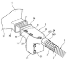
- FIG. 1 It is a schematic front view of 1st Embodiment of this invention. It is a perspective view of the state which the protector and grommet shown in FIG. 1 decomposed
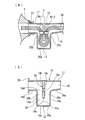
- (A) is sectional drawing of the state which has penetrated the wire harness in a protector
- (B) is sectional drawing before insertion of a wire harness. It is explanatory drawing at the time of wiring of a wire harness. The instrument which hold
- (A) is a perspective view
- (B) is drawing which shows the attachment groove
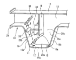
- (A) is a cross-sectional view taken along line AA in FIG. 6, and (B) is a cross-sectional view taken along line BB in FIG. (A) (B) is drawing which shows a prior art example.
- FIG. 1 show a first embodiment.
- the wire harness 1 is routed through a through hole H formed in the vehicle body panel P from the engine room (X) of the automobile to the passenger compartment (Y).
- a protector 5 is attached to the wire harness 1 continuously to the grommet 4 in order to prevent water from flowing from the engine room (X) to the passenger compartment (Y) through the gaps between the numerous electric wires 2 constituting the wire harness 1. ing.
- the electric wire 2 of the wire harness 1 is waterproofed through the corrugated tube 3 made of a resin molded product in the wiring area in the engine room (X).
- the wire harness 1 pulled out from the front end of the corrugated tube 3 is inserted into the protector 5 made of a resin molded product in a state where the wire group 2 is not bundled with an adhesive tape or the like.
- the wire group 2 that has passed through the protector 5 is inserted into a grommet 4 formed of rubber or elastomer connected to the front end of the protector 5.
- the grommet 4 is shaped to be attached to the inner peripheral surface of the through hole H of the vehicle body panel P in a sealed state.
- the protector 5 includes a protector body 10 and a lid 11 that covers and closes an opening on one side of the protector body 10.
- the wire harness 1 is bent and inserted in a downward U shape so that the water flowing through the gap of the wire group 2 can be drained from the drain hole 12 provided in the protector body 10.
- the protector body 10 includes a vertical wall 15 arranged in a vertical direction having a substantially T shape with a central portion 15a protruding downward, and upper and lower side edges of the vertical wall 15.
- the upper wall 17 and the lower wall 16 are projected in the horizontal direction.
- the upper wall 17 extends linearly along the horizontal upper side of the vertical wall 15.
- the lower wall 16 has a central portion projecting downward in a concave shape, and the lower wall of the central portion includes left and right side walls 16a and 16b and a bottom wall 16c between the lower ends of the left and right side walls.
- the drain hole 12 is provided in the center of the bottom wall 16c.
- Left and right side portions 16d and 16e facing the upper wall 17 in parallel are provided at the upper ends of the left and right side walls 16a and 16b.
- the lower end 18a of the pressing partition wall 18 has an arc shape, and dovetail mounting grooves 18d and 18e are provided on the left and right side surfaces 18b and 18c of the pressing partition wall 18, respectively. Further, as shown in FIG. 2, a lock frame 21 is provided with a gap on the protruding side of the outer surface of the lower wall 16 and the upper wall 17.
- a portion sandwiched between the protruding ends of the upper wall 17 and the lower wall 16 of the protector body 10 is a side opening, and the side opening is closed by the lid 11, and a position corresponding to the lock frame 21 at the periphery of the lid 11.
- a lock claw 22 is provided in a protruding manner.
- annular flange 29 having a rectangular frame shape for fitting is projected from the peripheral edge on the connection side with the grommet 4.
- the annular flange 29 is inserted into an annular fitting groove 23 provided on the inner surface on the connection side of the grommet 4 so that the protector 5 can be connected to the grommet 4.
- semi-cylindrical portions 24a and 24b are respectively projected from the protector body 10 and the lid 11 so as to project the cylindrical portion 24 corresponding to the outer diameter of the wire harness 1.
- the grommet 4 is provided with a rectangular tube portion 30 on the connection side with the protector 5 and the fitting groove 23 is provided on the inner surface thereof.
- a diameter-enlarged cylinder part 31 is provided on the large-diameter side of the diameter-enlarged cylinder part 31 so as to be enlarged by changing from a pyramid shape to a conical shape. ing.
- the grommet 4 is mounted in the through hole H in a sealed state by engaging and locking the vehicle body locking recess 32 in the through hole H of the vehicle body panel P.
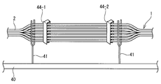
- the wire harness 1 is laid while supporting the wire group 2 with the wire receiving jig 41 on the wire harness assembly work table 40 to assemble the wire harness 1.
- a pair of appliances 44 (44-1, 44-2) are attached to both ends of the wire group 2 inserted through the protector 5, and the wire group 2 is held in parallel with a gap.
- the instrument 44 has a closing frame 44b connected to one end of a comb-shaped main body 44a via a hinge 44h.
- the wires arranged in the space 44d sandwiched between the comb teeth 44c of the main body 44a are sequentially passed and arranged in parallel. After all the wires are wired, the closing frame 44b is rotated and fixed to the other end of the main body 44a, and the devices 44-1 and 44-2 are attached to both ends of the wire 2 passing through the protector 5 and held in parallel. .
- the instruments 44-1 and 44-2 are inserted and locked into dovetail mounting grooves 18d and 18e provided on both sides of the pressing partition wall 18 in the protector body 10. I am going to do it. Therefore, the main body 44a is provided with an inclined protrusion 44g that fits into the dovetail.
- the wire harness 1 is attached to the protector 5 by inserting the wire harness 1 pulled out from the corrugated tube 3 into the protector body 10 through the U-shaped passage from the inlet side to the outlet side. Yes.
- the appliances 44-1 and 44-2 attached to the wire harness 1 are inserted and locked in the appliance attachment grooves 18d and 18e, and a large number of wires 2 of the wire harness 1 are arranged in parallel so that a gap is maintained in the bent passage. It is arranged.
- the cover 11 is covered, and the protector main body 10 and the cover 11 are locked together.
- the entrance side of the protector 5 and the corrugated tube 3 are fixed with an adhesive tape, and the exit side of the protector 5 is fitted and connected to the grommet 4 to assemble the wire harness.
- the protector 5 When the wire harness 1 sheathed with the corrugated tube 3, the protector 5, and the grommet 4 as described above is routed in an automobile and the grommet 4 is attached to the through hole H of the vehicle body panel P as shown in FIG. In succession, the protector 5 is positioned close to the vehicle body panel P in the engine room (X).
- the inside of the protector 5 In the downward U-shaped bent portion, the water droplet falls by its own weight and can be drained from the drain hole 12.
- the electric wire 2 is not bundled by wrapping an adhesive tape or the like at the bent portion, and is in a separated state and is held in parallel with a gap, moisture passing through the gap of the electric wire group is surely secured. It can be drained by dropping its own weight.
- the conventional water-stopping agent can be applied just by holding the wire harness through the pair of instruments 44-1 and 44-2 at the time of wiring, and the line-water-stopping process for winding the waterproof sheet around the application area is eliminated. Therefore, the water stop operation is simplified, labor saving can be achieved, and the manufacturing cost can be greatly reduced. In addition, variations in finish accuracy due to the skill level of workers can be eliminated, and water stoppage accuracy can be increased.
- the instruments 44-1 and 44-2 attached to the wire harness 1 are inserted into the dovetail-like attachment grooves 18d and 18e provided on both side surfaces of the pressing partition wall 18 in the protector body 10.
- the mounting grooves may be provided on the opposite left and right side walls 16a and 16b.
- it is not limited to the shape of a dovetail-shaped attachment groove, What is necessary is just to be able to attach the instrument 44.
- 6 and 7 show a second embodiment.
- the structure of the protector main body 10 of the protector 5 is made different from 1st Embodiment, and the shape which can arrange the electric wire group of the wire harness 1 in parallel inside the protector main body 10 is provided. Therefore, unlike the first embodiment, it is not necessary to use the instrument 44 in the wiring process of the wire harness 1, and the instrument 44 as a separate member can be dispensed with.
- the left and right sides of the central portion 15 a that protrudes downward from the protector body 10 are inclined close to each other downward to form a downward trapezoidal shape, and the left and right side walls 16 a and 16 b of the lower wall 16 are inclined walls. .
- a plurality of parallel holding protrusions 30 are formed on the upper side of the passage from the inner surface of the vertical wall 15 with a gap therebetween. Projecting so as to cross 20b.
- a plurality of parallel holding projections 31 project from the lower portion of the harness passage 20b at a position connecting the lower end of the pressing partition wall 18 and the lower end of the left side wall 16a with a gap therebetween.
- the electric wire group 2 of the wire harness 1 By passing the electric wire group 2 of the wire harness 1 through the gap between the parallel holding protrusions 30 and the parallel holding protrusion 31 that protrude vertically, the electric wire group of the wire harness 1 can be held in parallel with a gap. Therefore, the water droplets transmitted through the gaps between the wire groups of the wire harness 1 can be dropped by their own weight in the region where the harness passage 20a is inserted, and can be drained from the drain holes 12 provided on both sides of the bottom wall 16c.
- the lower end 18a of the pressing partition wall 18 is projected in a spherical shape.
- a water return protrusion 33 protruding in a downward J shape is provided on the left side wall 16a
- a water return protrusion 34 is also provided on the inner surface of the vertical wall 15.
Landscapes
- Engineering & Computer Science (AREA)
- Architecture (AREA)
- Civil Engineering (AREA)
- Structural Engineering (AREA)
- Mechanical Engineering (AREA)
- Installation Of Indoor Wiring (AREA)
Abstract
止水剤をワイヤハーネスに充填することなく、ワイヤハーネスの線間止水を確実に図る。車体パネルの貫通穴に装着するグロメットの被水側先端と嵌合接続するプロテクタを設け、該プロテクタから前記グロメットに連続して挿通させるワイヤハーネスの電線群は結束材で結束していない状態としており、前記プロテクタは、中央部を下方へ突出させると共に該中央部に押下用仕切壁を設けた縦壁と、該縦壁の上下端縁から突設した上壁および下壁とを備え、該下壁に水抜き穴を設けたプロテクタ本体と、該プロテクタ本体の縦壁と対向する開口を閉鎖する蓋とを備え、前記プロテクタ内に挿通する前記ワイヤハーネスの電線群を前記押下用仕切壁によりU形状に屈曲させると共に、隙間をあけた並列状態として挿通している。
Description
本発明はワイヤハーネスの止水構造に関し、詳しくは、自動車のエンジンルーム等の被水領域から車体パネルの貫通穴を通して車室内に配索するワイヤハーネスにおける車室内への浸水を防止するものである。
車体パネルに設ける貫通穴からの浸水は、ワイヤハーネスにグロメットを装着し、該グロメットを貫通穴の周縁にシール状態で取り付けることで浸水防止を図っている。
一方、ワイヤハーネスの電線群の隙間を毛細管現象で通って車室側へ浸水が生じる場合もある。該浸水はワイヤハーネスの電線群の間に止水剤を充填し、該止水剤の充填部で浸水を遮断して止水を図っている。この線間止水はワイヤハーネスの形成時に電線群を並列配置してシリコーン等の止水剤を塗布し、塗布した状態で電線群を丸めて防水シートを巻き付け、この状態でグロメット内に線間止水部を挿入している。
一方、ワイヤハーネスの電線群の隙間を毛細管現象で通って車室側へ浸水が生じる場合もある。該浸水はワイヤハーネスの電線群の間に止水剤を充填し、該止水剤の充填部で浸水を遮断して止水を図っている。この線間止水はワイヤハーネスの形成時に電線群を並列配置してシリコーン等の止水剤を塗布し、塗布した状態で電線群を丸めて防水シートを巻き付け、この状態でグロメット内に線間止水部を挿入している。
前記線間止水部を設けた構造とすると、車室側への止水を確実に図ることができる利点を有する。しかしながら、シリコーン等の止水剤の塗布、防水シートの巻き付け、該線間止水部のグロメットへの挿入等作業員が手作業で行う工程が比較的多く、作業手数がかかると共に作業員の熟練度による仕上精度にバラツキが生じ、改善の余地がある。
前記電線群中に止水剤を充填することなく電線群の隙間を通る浸水を遮断する手段として、特開昭60-96122号公報で図8(A)(B)に示す排水構造が提案されている。該排水構造では、車体貫通穴に装着するグロメット130から離れた位置で、ワイヤハーネス100をU形状に屈曲させ、図8(B)に示すプロテクタ110に通して、図8(A)に示すように、粘着テープ111で巻き付け固定し、屈曲部110aを下向きに突出させて配置している。かつ、該屈曲部110aの先端にテープ111を巻き付けず、電線を露出させた排水部150を設けている。このように、屈曲部110aの最下端の電線を露出させた排水部150から電線群の隙間を通る水を排水している。
前記特許文献1の排水構造はワイヤハーネスの屈曲部の最下端の電線群にテープを巻き付けずに露出させているため、車両走行中に撥ね上げた小石等が電線群に衝突する恐れがあり、また車体パネルのエッジとの接触、他部品との干渉や挟み込み等の外力から電線を保護することが困難で排水部の電線に損傷が生じる恐れがある。
さらに、撥ね上がった水が排水部から電線群中に浸水し、車室側に発生する負圧で車室側へ吸引されて浸透していく恐れがある。かつ、排水部150と車体パネルの貫通穴に装着するグロメット130との間のワイヤハーネス100の長さがかなり長いため、当該区間で電線群に巻き付けた結束テープの隙間を通して電線群中に浸水が生じることを確実に排除できず、止水精度の信頼性が低い。
さらに、撥ね上がった水が排水部から電線群中に浸水し、車室側に発生する負圧で車室側へ吸引されて浸透していく恐れがある。かつ、排水部150と車体パネルの貫通穴に装着するグロメット130との間のワイヤハーネス100の長さがかなり長いため、当該区間で電線群に巻き付けた結束テープの隙間を通して電線群中に浸水が生じることを確実に排除できず、止水精度の信頼性が低い。
本発明は前記問題に鑑みてなされたもので、ワイヤハーネスの電線群に止水剤を充填せず、かつ、電線群を外部に露出させた排水部を設けることなく、ワイヤハーネスの電線群の隙間を毛細管現象で通る水を排出して車室側への浸水発生を確実に防止することを課題としている。
前記課題を解決するため、本発明は、車体パネルの貫通穴に装着するグロメットの被水側先端と嵌合接続するプロテクタを設け、該プロテクタから前記グロメットに連続して挿通させるワイヤハーネスの電線群は結束材で結束していない状態としており、
前記プロテクタは、中央部を下方へ突出させると共に該中央部に押下用仕切壁を設けた縦壁と、該縦壁の上下端縁から突設した上壁および下壁とを備え、該下壁に水抜き穴を設けたプロテクタ本体と、該プロテクタ本体の縦壁と対向する開口を閉鎖する蓋とを備え、 前記プロテクタ内に挿通する前記ワイヤハーネスの電線群を前記押下用仕切壁によりU形状に屈曲させると共に、隙間をあけた並列状態として挿通していることを特徴とするワイヤハーネスの止水構造を提供している。
前記プロテクタは、中央部を下方へ突出させると共に該中央部に押下用仕切壁を設けた縦壁と、該縦壁の上下端縁から突設した上壁および下壁とを備え、該下壁に水抜き穴を設けたプロテクタ本体と、該プロテクタ本体の縦壁と対向する開口を閉鎖する蓋とを備え、 前記プロテクタ内に挿通する前記ワイヤハーネスの電線群を前記押下用仕切壁によりU形状に屈曲させると共に、隙間をあけた並列状態として挿通していることを特徴とするワイヤハーネスの止水構造を提供している。
前記のように、本発明では、グロメットにプロテクタを連結し、該プロテクタ内部でワイヤハーネスを押下用仕切壁に沿って屈曲させることで、下向きU形状に屈曲させ、屈曲部の下部に位置する下壁に水抜き穴を設けている。プロテクタ内に挿通するワイヤハーネスはテープ等を巻き付けて結束せずバラバラの状態とし、かつ、隙間をあけた並列状態とすることで、屈曲部で電線群の隙間を通る水滴を確実に自重落下させて排水できるようにしている。このように、車室に入る直前に配置したプロテクタにより、ワイヤハーネスの電線群中の浸水を止水剤で遮断することなく、確実に排水できる。かつ、ワイヤハーネスの電線群はバラバラの状態としているがプロテクタ内に通して保護しているため、外部材による干渉で損傷が生じることはない。
前記プロテクタ内で前記屈曲部のグロメット側のハーネス通路を通すワイヤハーネスの電線群を並列状態とし、該電線群を並列状態に保持する器具を取り付け、または前記プロテクタ本体の縦壁内面より並列状に突設した並列保持突起の間に前記電線群を区分けして通している。
前記プロテクタ挿通領域内でワイヤハーネスの電線群の両端に前記器具を取り付けており、該器具は櫛状本体に電線を並列して通した後に閉鎖枠で閉じる構成とし、前記ワイヤハーネスの布線工程時に取り付けている。
また、前記プロテクタ本体の押下用仕切壁の両側面、または押下用仕切壁とそれぞれ対向する下壁の両側面に前記器具を着脱自在に取り付ける取付溝を設けることが好ましい。
前記プロテクタ本体の縦壁内面より突設する並列保持突起は、該縦壁内面より水平方向に複数本を隙間をあけて突設し、突設位置は前記押下用仕切壁とグロメット連結側のプロテクタ本体の側壁との間に形成されるハーネス通路の上下2カ所とすることが好ましい。
該プロテクタ本体内にワイヤハーネスの電線群を挿通する際に前記並列保持突起の間の複数の隙間に電線群を略均等に区分けして通している。
該プロテクタ本体内にワイヤハーネスの電線群を挿通する際に前記並列保持突起の間の複数の隙間に電線群を略均等に区分けして通している。
また、前記プロテクタは、プロテクタ本体の中央部の下方突出形状を、前記押下用仕切壁を挟む両側壁を下方側で近接する方向に傾斜させた下向き台形状とし、側両側壁の下端間の底壁の両側または中央部に前記排水穴を設けている。かつ、グロメット連結側の傾斜側壁と押下用仕切壁の間のハーネス通路に突出するように前記傾斜側壁と前記縦壁から水返し突起を設け、前記排水穴からの浸水が生じても、前記水返し突起で落下させ排水穴から排水できるようにしている。
前記プロテクタ本体の上壁と下壁の突出端側にロック枠を設ける一方、プロテクタの蓋の対応位置にロック爪を設け、プロテクタ本体にワイヤハーネスの電線群を通した後に蓋をロック結合できるようにしている。かつ、プロテクタ本体に蓋を取り付けた状態でグロメット連結側の出口周縁から嵌合用の環状フランジを突設させ、グロメットの接続端側の内面に設けた環状の嵌合溝に内嵌して連結できるようにしている。一方、反対側の入口側ではワイヤハーネスの外径に対応した円筒部が突出し、該円筒部の外周面からワイヤハーネスの外周面にかけて粘着テープを巻き付けている。
前記プロテクタおよびグロメットに通すワイヤハーネスは、被水領域となる自動車のエンジンルーム内に配索し、前記プロテクタに達するまではコルゲートチューブで外装し又は粘着テープを巻きつけて外装し、前記プロテクタに連結する前記グロメットをエンジンルームと車室とを仕切るパネルの貫通穴に装着することが好ましい。
前記のように、本発明では、グロメットにプロテクタを連結させ、該プロテクタ内でワイヤハーネスを強制的に下向きU形状に屈曲させると共に、プロテクタ内では電線をバラバラの状態で並列配置しているため、電線群の隙間を浸透する水を確実に自重落下させて水抜き穴から排水できる。よって、止水剤を電線群の隙間に充填させる線間止水処理する必要はなく、作業工程を単純化して大幅な省力化をはかれる。かつ、止水精度にバラツキを無くすと共に、止水精度自体を高めることができる。
以下、本発明のワイヤハーネスの止水構造の実施形態を図面を参照して詳述する。
図1乃至図5に第1実施形態を示す。
図1に示すように、自動車のエンジンルーム(X)から車室(Y)に車体パネルPに穿設した貫通穴Hを通してワイヤハーネス1を配索している。該ワイヤハーネス1を構成する多数の電線2の隙間を通してエンジンルーム(X)から車室(Y)へ浸水が生じるのを防止するため、ワイヤハーネス1にはグロメット4に連続してプロテクタ5を取り付けている。
図1乃至図5に第1実施形態を示す。
図1に示すように、自動車のエンジンルーム(X)から車室(Y)に車体パネルPに穿設した貫通穴Hを通してワイヤハーネス1を配索している。該ワイヤハーネス1を構成する多数の電線2の隙間を通してエンジンルーム(X)から車室(Y)へ浸水が生じるのを防止するため、ワイヤハーネス1にはグロメット4に連続してプロテクタ5を取り付けている。
前記ワイヤハーネス1の電線2は、エンジンルーム(X)内の配索領域では樹脂成形品からなるコルゲートチューブ3内を通して防水仕様としている。該コルゲートチューブ3の前端から引き出されるワイヤハーネス1を樹脂成形品からなる前記プロテクタ5内に電線群2を粘着テープ等で結束していないバラバラにした状態で挿通している。該プロテクタ5を通した電線群2は、プロテクタ5の前端に連結したゴムまたはエラストマーで成形したグロメット4に挿通している。該グロメット4は車体パネルPの貫通穴Hの内周面にシール状態で装着する形状としている。
前記プロテクタ5は図2に示すように、プロテクタ本体10と該プロテクタ本体10の一側面の開口に被せて閉鎖する蓋11とからなる。該プロテクタ5の内部でワイヤハーネス1を下向きU形状に屈曲させて挿通させ、該プロテクタ本体10に設けた水抜き穴12から電線群2の隙間を通る浸水を排水できるようにしている。
前記プロテクタ本体10は、図3(A)(B)に示すように、中央部15aを下方へ突出させた略T形状の垂直方向に配置する縦壁15と、該縦壁15の上下両側縁に沿って水平方向に突出させる上壁17と下壁16とからなる。上壁17は縦壁15の水平方向の上辺に沿って直線状に延在させている。一方、下壁16は中央部を下向きに凹形状に突出させ、中央部の下壁は左右両側壁16a、16bと、該左右両側壁の下端間の底壁16cとからなる。該底壁16cの中央に前記水抜き穴12を設けている。左右両側壁16a、16bの上端に前記上壁17と平行に対向する左右両側部16d、16eを設けている。
上壁17の中央下面で且つ縦壁15の中央部15aの内面の中央には、上壁17の下面に接する上端から前記下壁16の左右両側壁16aと16bに挟まれた部分にかけて押下用仕切壁18を突設している。該押下用仕切壁18の下端18aと前記底壁16cとの間にハーネス通路20の最下部20aとなる隙間を空けて位置させている。かつ、押下用仕切壁18の左右両側面18b、18cと対向する前記左右両側壁16a、16bとの間にそれぞれハーネス通路20の通路20b、20cを設け、前記最下端の通路20aと連続させ、前記通路20c-20a-20bを連続させたU形状の屈曲通路を形成している。
前記押下用仕切壁18の下端18aは円弧状にすると共に、押下用仕切壁18の左右両側面18b、18cに蟻溝状の取付溝18d、18eを設けている。
さらに、図2に示すように、下壁16および上壁17の外面の突出側に間隔をあけてロック枠21を設けている。
さらに、図2に示すように、下壁16および上壁17の外面の突出側に間隔をあけてロック枠21を設けている。
プロテクタ本体10の上壁17と下壁16の突出端に挟まれた部分は側面開口となり、該側面開口を前記蓋11で閉鎖するものとし、蓋11の周縁で前記ロック枠21と対応する位置にロック爪22を突設している。
前記プロテクタ本体10に蓋11を取り付けた状態でグロメット4との連結側周縁から嵌合用の四角枠状とした環状フランジ29を突設している。該環状フランジ29はグロメット4の接続側の内面に設けた環状の嵌合溝23に押し込んで内嵌することで、プロテクタ5をグロメット4に連結できるようにしている。
一方、反対側の入口側ではワイヤハーネス1の外径に対応した円筒部24を突出するように、プロテクタ本体10と蓋11からそれぞれ半円筒部24a、24bをそれぞれ突設している。該円筒部24にワイヤハーネス1に外装した前記コルゲートチューブ3の前端を挿入した後、粘着テープを巻き付けて固着するようにしている。
一方、反対側の入口側ではワイヤハーネス1の外径に対応した円筒部24を突出するように、プロテクタ本体10と蓋11からそれぞれ半円筒部24a、24bをそれぞれ突設している。該円筒部24にワイヤハーネス1に外装した前記コルゲートチューブ3の前端を挿入した後、粘着テープを巻き付けて固着するようにしている。
グロメット4は、プロテクタ5との連結側に四角筒部30を設け、その内面に前記嵌合溝23を設けている。該四角筒部30に連続して角錐形状から円錐形状へと変化させて拡径する拡径筒部31を設け、該拡径筒部31の大径側に車体係止凹部32を環状に設けている。該車体係止凹部32を車体パネルPの貫通穴Hに内嵌係止することでグロメット4を貫通穴Hにシール状態で装着するようにしている。
前記ワイヤハーネス1は図4に示すように、ワイヤハーネス組立作業台40上で電線群2を電線受け治具41で支持しながら布線して、ワイヤハーネス1を組み立てている。この布線工程時に、プロテクタ5内を挿通する電線群2の両端に一対の器具44(44-1、44-2)を取り付け、電線群2を隙間をあけて並列保持している。
器具44は図5に示すように、櫛状の本体44aの一端に閉鎖枠44bをヒンジ44hを介して連結してる。本体44aの櫛歯44cに挟まれた空間44dに布線する電線を順次通して並列配置している。すべての電線を布線した後に閉鎖枠44bを回転して本体44aの他端に固定し、プロテクタ5内に通す電線2の両端に器具44-1、44-2を取り付けて並列保持している。
ワイヤハーネス1をプロテクタ5内に挿通した時、器具44-1と44-2はプロテクタ本体10内で押下用仕切壁18の両側面に設けた蟻溝状の取付溝18d、18eに挿入係止するものとしている。よって、本体44aに蟻溝に嵌合する傾斜突起44gを設けている。
前記ワイヤハーネス1のプロテクタ5への取り付けは、プロテクタ5のプロテクタ本体10内に、コルゲートチューブ3から引き出したワイヤハーネス1を入口側からU形状に屈曲した通路をへて出口側へと挿通させている。ワイヤハーネス1に取り付けた前記器具44-1、44-2を器具取付溝18d、18eに挿入係止し、該屈曲通路ではワイヤハーネス1の多数の電線2を互いに隙間が保持されるように並列配置している。
前記のように、プロテクタ本体10にワイヤハーネス1を通した後に蓋11を被せ、プロテクタ本体10と蓋11とをロック結合している。該プロテクタ5の入口側とコルゲートチューブ3とを粘着テープで固着すると共に、プロテクタ5の出口側をグロメット4と嵌合接続して、ワイヤハーネスを組み立てている。
前記のようにコルゲートチューブ3、プロテクタ5、グロメット4で外装したワイヤハーネス1を自動車に配索し、図1に示すように、グロメット4を車体パネルPの貫通穴Hに装着すると、該グロメット4に連続してプロテクタ5がエンジンルーム(X)内で車体パネルPに近接して位置することになる。
自動車走行時にエンジンルーム(X)側でワイヤハーネス1の電線群中に浸水した水が毛細管現象と車室(Y)側で発生する負圧により車室側へと浸透しても、プロテクタ5内部で下向きU字状の屈曲部で水滴が自重落下し水抜き穴12から排水できる。かつ、該屈曲部では電線2は、粘着テープ等を巻き付けて結束しておらず、バラバラの状態であり、さらに、隙間をあけて並列保持されているため、電線群の隙間を通す水分を確実に自重落下させて排水することができる。
また、ワイヤハーネスを組み立てる布線時に一対の器具44-1、44-2を通して並列保持するだけで、従来の止水剤を塗布し、該塗布領域に防水シートを巻き付ける線間止水工程を無くしているため、止水作業が簡単となり、省力化を図ることができ、製造コストを大幅に低減できる。かつ、作業員の熟練度による仕上がり精度のバラツキを無くすことができ、止水精度を高めることもできる。
前記実施形態では、ワイヤハーネス1に取り付けている器具44-1と44-2を、プロテクタ本体10内で押下用仕切壁18の両側面に設けた蟻溝状の取付溝18d、18eに挿入係止するものとしているが、該取付溝を対向する左右両側壁16a、16bに設けてもよい。なお、蟻溝状の取付溝の形状に限定されず、器具44を取り付けることができればよい。
図6および図7に第2実施形態を示す。
第2実施形態では、プロテクタ5のプロテクタ本体10の構成を第1実施形態と相違させ、プロテクタ本体10の内部でワイヤハーネス1の電線群を並列配置できる形状を設けている。よって、第1実施形態のようにワイヤハーネス1の布線工程で器具44を用いて配列布線する必要はなく、別部材の器具44を不要にできる。
第2実施形態では、プロテクタ5のプロテクタ本体10の構成を第1実施形態と相違させ、プロテクタ本体10の内部でワイヤハーネス1の電線群を並列配置できる形状を設けている。よって、第1実施形態のようにワイヤハーネス1の布線工程で器具44を用いて配列布線する必要はなく、別部材の器具44を不要にできる。
図6に示すように、プロテクタ本体10の下方へ突出させた中央部15aの左右両側は下向きに近接させて傾斜とし下向き台形状とし、下壁16の左右両側壁16a、16bを傾斜壁としている。
押下用仕切壁18とグロメット連結側の左側壁16aとに挟まれたハーネス通路20bには、該通路の上部側に縦壁15の内面から複数本の並列保持突起30を隙間をあけてハーネス通路20bを横断するように突設している。また、該ハーネス通路20bの下部側で押下用仕切壁18の下端と左側壁16aの下端とを結ぶ位置にも複数本の並列保持突起31を間隔をあけて突設している。
上下に突設する並列保持突起30の隙間および並列保持突起31の隙間にそれぞれワイヤハーネス1の電線群2を通して行くことで、ワイヤハーネス1の電線群を隙間をあけて並列保持できる。よって、ハーネス通路20aを挿通する領域でワイヤハーネス1の電線群の隙間を伝う水滴を自重落下させることができ、底壁16cの両側に設けた水抜き穴12より排水できる。
また、押下用仕切壁18の下端18aを球状に突出させている。かつ、前記左側壁16aには下向きJ字状に突設した水返し突起33を突設すると共に、縦壁15の内面からも水返し突起34を突設している。これら水返し突起33と34を設けることで、水抜き穴12からプロテクタ本体10の内部に浸水が生じ、左側壁16a、縦壁15の内面に沿って浸透していく水があっても、水返し突起33、34により浸透を阻止できる。かつ、押下用仕切壁18の下端18aを球状に突出させているため、押下用仕切壁18に下端から水が浸水してくるのを防止できる。
他の構成は前記第1実施形態と同様であり、かつ、同様の作用効果を有するため、同一符号を付して、説明を省略する。
1 ワイヤハーネス
2 電線群
3 コルゲートチューブ
4 グロメット
5 プロテクタ
10 プロテクタ本体
11 蓋
12 水抜き穴
15 縦壁
16 下壁
17 上壁
18 押下用仕切壁
44 器具
2 電線群
3 コルゲートチューブ
4 グロメット
5 プロテクタ
10 プロテクタ本体
11 蓋
12 水抜き穴
15 縦壁
16 下壁
17 上壁
18 押下用仕切壁
44 器具
Claims (6)
- 車体パネルの貫通穴に装着するグロメットの被水側先端と嵌合接続するプロテクタを設け、該プロテクタから前記グロメットに連続して挿通させるワイヤハーネスの電線群は結束材で結束していない状態としており、
前記プロテクタは、中央部を下方へ突出させると共に該中央部に押下用仕切壁を設けた縦壁と、該縦壁の上下端縁から突設した上壁および下壁とを備え、該下壁に水抜き穴を設けたプロテクタ本体と、該プロテクタ本体の縦壁と対向する開口を閉鎖する蓋とを備え、 前記プロテクタ内に挿通する前記ワイヤハーネスの電線群を前記押下用仕切壁によりU形状に屈曲させると共に、隙間をあけた並列状態として挿通していることを特徴とするワイヤハーネスの止水構造。 - 前記プロテクタ内で前記屈曲部のグロメット側のハーネス通路を通すワイヤハーネスの電線群を並列状態とし、該電線群を並列状態に保持する器具を取り付け、または前記プロテクタ本体の縦壁内面より並列状に突設した並列保持突起の間に前記電線群を区分けして通している請求項1に記載のワイヤハーネスの止水構造。
- 前記プロテクタ挿通領域内でワイヤハーネスの電線群の両端に前記器具を取り付けており、該器具は櫛状本体に電線を並列して通した後に閉鎖枠で閉じる構成とし、前記ワイヤハーネスの布線工程時に取り付けている請求項2に記載のワイヤハーネスの止水構造。
- 前記プロテクタ本体の押下用仕切壁の両側面、または押下用仕切壁とそれぞれ対向する下壁の両側面に前記器具を着脱自在に取り付ける取付溝を設けている請求項2または請求項3に記載のワイヤハーネスの止水構造。
- 前記プロテクタ本体の縦壁内面より突設する並列保持突起は、該縦壁内面より水平方向に複数本を隙間をあけて突設し、突設位置は前記押下用仕切壁とグロメット連結側のプロテクタ本体の側壁との間に形成されるハーネス通路の上下2カ所である請求項2に記載のワイヤハーネスの止水構造。
- 前記プロテクタおよびグロメットに通すワイヤハーネスは、被水領域となる自動車のエンジンルーム内に配索し、前記プロテクタに達するまではコルゲートチューブで外装し又は粘着テープをハーフラップ巻きして外装し、前記プロテクタに連結する前記グロメットをエンジンルームと車室とを仕切るパネルの貫通穴に装着するものとしている請求項1乃至請求項5のいずれか1項に記載のワイヤハーネスの止水構造。
Applications Claiming Priority (2)
| Application Number | Priority Date | Filing Date | Title |
|---|---|---|---|
| JP2011123673A JP5768509B2 (ja) | 2011-06-01 | 2011-06-01 | ワイヤハーネスの止水構造 |
| JP2011-123673 | 2011-06-01 |
Publications (1)
| Publication Number | Publication Date |
|---|---|
| WO2012164772A1 true WO2012164772A1 (ja) | 2012-12-06 |
Family
ID=47258654
Family Applications (1)
| Application Number | Title | Priority Date | Filing Date |
|---|---|---|---|
| PCT/JP2011/076993 Ceased WO2012164772A1 (ja) | 2011-06-01 | 2011-11-24 | ワイヤハーネスの止水構造 |
Country Status (2)
| Country | Link |
|---|---|
| JP (1) | JP5768509B2 (ja) |
| WO (1) | WO2012164772A1 (ja) |
Cited By (2)
| Publication number | Priority date | Publication date | Assignee | Title |
|---|---|---|---|---|
| CN110635420A (zh) * | 2018-06-22 | 2019-12-31 | 矢崎总业株式会社 | 索环 |
| US11336080B1 (en) | 2021-01-11 | 2022-05-17 | Woodward, Inc. | Slotted grommet |
Families Citing this family (5)
| Publication number | Priority date | Publication date | Assignee | Title |
|---|---|---|---|---|
| JP6774820B2 (ja) * | 2016-09-05 | 2020-10-28 | 古河電気工業株式会社 | ワイヤハーネス用グロメット及びプロテクタ |
| JP7072349B2 (ja) * | 2017-03-22 | 2022-05-20 | ダイハツ工業株式会社 | コネクタの保持構造 |
| JP7166077B2 (ja) * | 2018-06-06 | 2022-11-07 | 矢崎総業株式会社 | 屈曲プロテクタ |
| JP7640299B2 (ja) * | 2021-03-16 | 2025-03-05 | 古河電気工業株式会社 | 電線ケース及びカバー付き電線 |
| KR102787894B1 (ko) * | 2022-11-29 | 2025-03-28 | 주식회사 유라코퍼레이션 | 정션블록의 수분유입 방지구조 |
Citations (3)
| Publication number | Priority date | Publication date | Assignee | Title |
|---|---|---|---|---|
| JPH0562133U (ja) * | 1992-01-29 | 1993-08-13 | 日産車体株式会社 | ハーネス配索構造 |
| JP2002058140A (ja) * | 2000-05-30 | 2002-02-22 | Yazaki Corp | グロメット |
| JP2008143325A (ja) * | 2006-12-08 | 2008-06-26 | Sumitomo Wiring Syst Ltd | ドア用ワイヤハーネスの配索構造 |
-
2011
- 2011-06-01 JP JP2011123673A patent/JP5768509B2/ja not_active Expired - Fee Related
- 2011-11-24 WO PCT/JP2011/076993 patent/WO2012164772A1/ja not_active Ceased
Patent Citations (3)
| Publication number | Priority date | Publication date | Assignee | Title |
|---|---|---|---|---|
| JPH0562133U (ja) * | 1992-01-29 | 1993-08-13 | 日産車体株式会社 | ハーネス配索構造 |
| JP2002058140A (ja) * | 2000-05-30 | 2002-02-22 | Yazaki Corp | グロメット |
| JP2008143325A (ja) * | 2006-12-08 | 2008-06-26 | Sumitomo Wiring Syst Ltd | ドア用ワイヤハーネスの配索構造 |
Cited By (2)
| Publication number | Priority date | Publication date | Assignee | Title |
|---|---|---|---|---|
| CN110635420A (zh) * | 2018-06-22 | 2019-12-31 | 矢崎总业株式会社 | 索环 |
| US11336080B1 (en) | 2021-01-11 | 2022-05-17 | Woodward, Inc. | Slotted grommet |
Also Published As
| Publication number | Publication date |
|---|---|
| JP5768509B2 (ja) | 2015-08-26 |
| JP2012253877A (ja) | 2012-12-20 |
Similar Documents
| Publication | Publication Date | Title |
|---|---|---|
| JP5768509B2 (ja) | ワイヤハーネスの止水構造 | |
| CN101102036B (zh) | 线束防水结构 | |
| JP5151701B2 (ja) | ワイヤハーネスの排水構造 | |
| US9905337B2 (en) | Sealing structure of multicore cable | |
| US9029701B2 (en) | Wire harness protector | |
| WO2012098704A1 (ja) | ワイヤハーネス用のプロテクタ | |
| JP2011010474A (ja) | ワイヤハーネス用プロテクタ | |
| JP3770462B2 (ja) | グロメット | |
| JPH07105742A (ja) | ワイヤハーネスの防水構造 | |
| WO1991017552A1 (en) | Method for sealing a cable harness in longitudinal direction and flexible element to carry out the method | |
| JP2007068312A (ja) | ワイヤーハーネス経路に止水構造を備えた樹脂成形構造体 | |
| JP5131087B2 (ja) | ワイヤハーネス用プロテクタ | |
| JP2016140140A (ja) | 電線群保護具およびワイヤハーネス | |
| JP7210314B2 (ja) | ワイヤハーネス用の止水具、コネクタホルダ、及びワイヤハーネスの止水構造 | |
| JP7640299B2 (ja) | 電線ケース及びカバー付き電線 | |
| JP7110866B2 (ja) | 光ファイバケーブルおよび光ファイバケーブルの接続構造。 | |
| JP2017163664A (ja) | 電線のプロテクタ保護構造 | |
| JP2010068613A (ja) | ワイヤハーネス | |
| JP2556706Y2 (ja) | ワイヤハーネスの防水構造 | |
| JPH06276643A (ja) | ワイヤハーネス用防水樹脂筒 | |
| JPH06276642A (ja) | ワイヤハーネスの防水構造 | |
| KR100659970B1 (ko) | 행거 기능을 가진 가설용 전선 케이블 묶음 장치. | |
| JP2016051626A (ja) | ワイヤーハーネス | |
| JP2016158466A (ja) | コルゲートチューブ及びそれを用いたワイヤハーネスの水抜構造 | |
| JP2005112023A (ja) | 配線・配管用ハーネスの取付け構造 |
Legal Events
| Date | Code | Title | Description |
|---|---|---|---|
| 121 | Ep: the epo has been informed by wipo that ep was designated in this application |
Ref document number: 11866954 Country of ref document: EP Kind code of ref document: A1 |
|
| NENP | Non-entry into the national phase |
Ref country code: DE |
|
| 122 | Ep: pct application non-entry in european phase |
Ref document number: 11866954 Country of ref document: EP Kind code of ref document: A1 |