WO2012164771A1 - ワイヤーハーネス配索構造及びその製造方法 - Google Patents
ワイヤーハーネス配索構造及びその製造方法 Download PDFInfo
- Publication number
- WO2012164771A1 WO2012164771A1 PCT/JP2011/075539 JP2011075539W WO2012164771A1 WO 2012164771 A1 WO2012164771 A1 WO 2012164771A1 JP 2011075539 W JP2011075539 W JP 2011075539W WO 2012164771 A1 WO2012164771 A1 WO 2012164771A1
- Authority
- WO
- WIPO (PCT)
- Prior art keywords
- wire harness
- regulating member
- path regulating
- nonwoven fabric
- path
- Prior art date
- Legal status (The legal status is an assumption and is not a legal conclusion. Google has not performed a legal analysis and makes no representation as to the accuracy of the status listed.)
- Ceased
Links
Images


Classifications
-
- H—ELECTRICITY
- H02—GENERATION; CONVERSION OR DISTRIBUTION OF ELECTRIC POWER
- H02G—INSTALLATION OF ELECTRIC CABLES OR LINES, OR OF COMBINED OPTICAL AND ELECTRIC CABLES OR LINES
- H02G3/00—Installations of electric cables or lines or protective tubing therefor in or on buildings, equivalent structures or vehicles
- H02G3/30—Installations of cables or lines on walls, floors or ceilings
-
- B—PERFORMING OPERATIONS; TRANSPORTING
- B60—VEHICLES IN GENERAL
- B60R—VEHICLES, VEHICLE FITTINGS, OR VEHICLE PARTS, NOT OTHERWISE PROVIDED FOR
- B60R16/00—Electric or fluid circuits specially adapted for vehicles and not otherwise provided for; Arrangement of elements of electric or fluid circuits specially adapted for vehicles and not otherwise provided for
- B60R16/02—Electric or fluid circuits specially adapted for vehicles and not otherwise provided for; Arrangement of elements of electric or fluid circuits specially adapted for vehicles and not otherwise provided for electric constitutive elements
- B60R16/0207—Wire harnesses
- B60R16/0215—Protecting, fastening and routing means therefor
Definitions
- the present invention relates to a wiring structure of a wire harness that is wired to a vehicle.
- a route restriction member may be attached to a wire harness routed in a vehicle in order to restrict the route.
- the resin rod extended straightly is applied in parallel with the axial direction of a wire harness on the outer periphery of the electric wire group which comprises a wire harness.
- the resin rod and the wire harness are taped and integrated.
- the wire harness is restricted in a predetermined direction, or the wire harness is prevented from being bent in an unintended direction.
- an object of the present invention is to provide a technique for easily realizing a wire harness regulating structure excellent in silence.
- a first aspect is a wire harness routing structure for routing a wire harness, which is formed by hot pressing a wire harness and a nonwoven fabric, and is bundled together with the wire harness And a path regulating member that regulates the routing path of the wire harness.
- a 2nd aspect is a wire harness wiring structure which concerns on a 1st aspect, WHEREIN:
- route control member is the base part extended along the extension direction of the said wire harness, and the said outer periphery part of the said base part.
- a flexible portion provided along the extending direction of the base portion and formed more flexibly than the base portion.
- the third aspect is a wire harness wiring structure according to the first or second aspect, wherein the flexible portion is provided on both sides of the base portion.
- the fourth aspect is a wire harness routing structure according to any one of the first to third aspects, and includes a portion where the route restriction member extends while bending.
- a 5th aspect is a manufacturing method of the wire harness wiring structure which wires a wire harness, Comprising: (a) The process of shape
- a portion that is not hot-pressed is set at the end of the nonwoven fabric.
- the path regulating member According to the path regulating member according to the first to fourth aspects, it is possible to suppress the abnormal noise generated when contacting the surrounding members by being formed of the nonwoven fabric. Therefore, the silence of the wire harness wiring structure can be improved.
- the flexible portion that is more flexible than the base portion is formed at the end of the base portion, abnormal noise is generated even when the flexible portion comes into contact with surrounding members. Is suppressed. Therefore, the silence of the wire harness wiring structure can be improved.
- the wire harness wiring structure by providing the flexible portions on both sides of the base portion, it is possible to suppress the generation of noise due to contact with surrounding members on both sides of the base portion.
- the wire harness routing structure it is possible to regulate the path so that the wire harness is bent. Further, by forming the path regulating member with a non-woven fabric, a bent structure can be easily manufactured.
- the wire harness wiring structure when the nonwoven fabric is used, it can be deformed into a desired shape when cooled. Therefore, the wire harness wiring structure corresponding to various wiring patterns of the wire harness can be easily manufactured.
- the flexibility of the end portion of the nonwoven fabric can be improved. Therefore, the wire harness wiring structure excellent in silence can be manufactured.
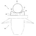
- Drawing 1 is an outline perspective view of wire harness wiring structure 10 concerning an embodiment.
- 2 is a cross-sectional view taken along line II-II shown in FIG.
- the wire harness routing structure 10 includes a wire harness 30 and a path regulating member 20 attached to the wire harness 30.
- the wire harness routing structure 10 is a structure for routing the wire harness 30 so as to extend in a required direction.
- the wire harness 30 a linear body such as an electric wire or an optical fiber cable that interconnects various electric devices in a vehicle or the like is assumed.
- the wire harness 30 attached to the route regulating member 20 of the present application may be a single linear body or may be composed of a plurality of linear bodies.
- the path regulating member 20 is formed by hot pressing a nonwoven fabric. By attaching the wire harness 30 to the route restriction member 20, the routing route of the wire harness 30 is restricted.
- the nonwoven fabric a nonwoven fabric that can be hardened through a heating process can be used.
- a non-woven fabric one containing basic fibers that are intertwined with each other and an adhesive resin (also called a binder) can be used.
- the adhesive resin is a resin having a melting point (for example, 110 to 115 degrees Celsius) lower than the melting point of the basic fiber.
- the adhesive resin may be granular or fibrous.
- An adhesive resin layer may be formed on the outer periphery of the core fiber to form a binder fiber, which may be entangled with the basic fiber.
- the core fiber in this case, the same material as the basic fiber can be used.
- the basic fiber it is only necessary to maintain the fiber state at the melting point of the adhesive resin, and various fibers can be used in addition to the resin fiber.
- the adhesive resin thermoplastic resin fibers having a melting point lower than that of the basic fiber can be used.
- the combination of the basic fiber and the adhesive resin include an example in which the basic fiber is a resin fiber of PET (polyethylene terephthalate) and the adhesive resin is a copolymer resin of PET and PEI (polyethylene isophthalate).
- the melting point of the basic fiber is approximately 250 degrees Celsius
- the melting point of the adhesive resin is approximately 110 degrees Celsius to 150 degrees Celsius.
- the adhesive resin when the non-woven fabric is heated to a temperature of 110 to 250 degrees Celsius, the adhesive resin is melted and soaked between the basic fibers that keep the fiber shape without melting. And when a nonwoven fabric becomes temperature lower than melting
- hot press refers to molding a nonwoven fabric by sandwiching a nonwoven fabric, which is an object to be processed, between molds and applying pressure to the mold in a heated state.
- An example of hot pressing suitable for manufacturing the path regulating member 20 according to the present embodiment will be described in detail later.
- the path regulating member 20 is bent halfway. For this reason, when the wire harness 30 is attached along the path regulating member 20, the wire harness 30 is routed while being bent along the path regulating member 20.
- the bending direction of the path regulating member 20 is not limited to that in the horizontal plane, and can be any direction including the vertical direction.
- route control member 20 may be bent only in one place, and may be bent in several places.
- the path regulating member 20 has a flat portion 21 (base portion) whose upper surface is flat along the extending direction.
- the upper surface of the flat portion 21 forms a mounting surface on which the wire harness 30 is mounted.
- the path regulating member 20 and the wire harness 30 are integrated by tape winding or the like.
- the path regulating member 20 is excellent in buffering properties, so that the generation of abnormal noise due to contact with other members is hardly suppressed. . Therefore, it is not necessary to wind the tape so as to completely cover the path regulating member 20.
- the path regulating member 20 and the wire harness 30 may be integrated with an annular band member or an adhesive.
- a concave portion corresponding to the shape of the wire harness 30 may be provided in a placement portion on which the wire harness 30 is placed so that the wire harness 30 can be installed in the concave portion. In this case, it becomes easy to fix the wire harness 30 to the path regulating member 20. Further, the wire harness 30 may be attached to the lower side of the path regulating member 20 (the side on which the protrusion 23 is not formed).
- Protruding portions 23 and 23 projecting upward along the extending direction of the path regulating member 20 are provided at both ends of the upper portion of the flat portion 21 (the portion on which the wire harness 30 is placed).
- the wire harness 30 is installed at a position between the protrusions 23 on both sides.
- the protrusion 23 is formed to be more flexible than the flat portion 21.
- the protrusion 23 is formed most flexibly by hot pressing the nonwoven fabric with a hot pressing mold 50 described later.
- the projection part 23 is a flexible part.
- both end portions of the path regulating member 20 are formed to have flexibility next to the protruding portion 23.
- the flat part 21 is formed so that it may become harder than the both ends of the projection part 23 and the path
- the route restriction member 20 collides with surrounding members when the route restriction member 20 is attached to the vehicle.
- the generation of abnormal noise can be suppressed.
- a clamp structure 40 may be attached to the lower part of the path regulating member 20 as indicated by a two-dot broken line.
- the clamp structure 40 is a member that fixes the wire harness wiring structure 10 attached to the clamp structure 40 by being fitted to a hole or the like formed in a vehicle (not shown). By combining such a clamp structure 40 and the path regulating member 20, the wire harness 30 can be fixed at a required position in the vehicle.
- the path regulating member 20 can be manufactured by (a) forming a substantially linear shape by hot pressing a nonwoven fabric and (b) deforming the hot pressed nonwoven fabric while cooling. And (c) The wire harness wiring structure 10 can be manufactured by attaching the wire harness 30 to the path
- FIG. 3 is a schematic perspective view showing an example of a hot pressing mold 50 for manufacturing the path regulating member 20.
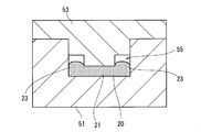
- FIG. 4 is a schematic cross-sectional view of a hot pressing mold 50.
- the hot pressing mold 50 includes a lower mold 51 and an upper mold 53 combined with the lower mold 51.
- the side on which the lower mold 51 is disposed is the lower side
- the side on which the upper mold 53 is disposed is the upper side.
- the lower mold 51 and the upper mold 53 are long members formed of a metal having excellent thermal conductivity.
- a substantially rectangular parallelepiped groove 511 (concave portion) is formed that extends linearly along the longitudinal direction and opens upward.
- a convex portion 531 that is fitted into the rectangular parallelepiped groove 511 of the lower die 51 is formed along the longitudinal direction. Corner portions at both ends of the convex portion 531 in the width direction (direction orthogonal to the longitudinal direction) have a stepped shape by forming a substantially rectangular parallelepiped cutout 54 along the longitudinal direction.
- the lower mold 51 and the upper mold 53 are provided with a heater (not shown) as a heating device.
- a heater heats the part which contacts a nonwoven fabric among the lower mold
- the heater may be embedded in the lower mold 51 and the upper mold 53, or may be attached to the lower mold 51 and the upper mold 53 in a manner capable of transferring heat.
- a non-woven fabric path regulating member 20
- the convex portion of the upper mold 53 in the groove 511 of the lower mold 51. 531 is attached.
- pressure is applied between the lower mold 51 and the upper mold 53.
- the convex part 531 of the upper mold 53 is pressed against the nonwoven fabric in the groove 511 of the lower mold 51.
- the portion pressed against the convex portion 531 corresponds to the flat portion 21 in the final form of the path regulating member 20.
- a gap 55 is formed between the upper mold 53 and the nonwoven fabric along the longitudinal direction of the hot pressing mold 50. (FIG. 4). That is, non-pressing portions that are not pressed by the upper mold 53 (that is, portions that are not hot pressed) are formed at both ends in the width direction of the path regulating member 20.
- the non-pressed portion is a portion that is less easily heated than the portion of the nonwoven fabric on which the convex portion 531 is pressed. Therefore, in this non-pressed portion, since the adhesive resin is not sufficiently heated, it is difficult for the adhesive resin to penetrate between the basic fibers. Therefore, when the heated nonwoven fabric is cooled and cured, the non-pressed portion is formed so as to slightly swell while maintaining the inherent flexibility of the nonwoven fabric to some extent. As a result, the projection 23 is formed in the final form of the path regulating member 20.
- the peripheral portion of the non-pressed portion is in contact with the side surface and bottom surface of the groove 511 of the lower mold 51, but is not pressed from above. Therefore, although heated more easily than the non-pressed portion, it is less likely to be heated than the portion pressed by the convex portion 531. Therefore, both end portions in the width direction of the path regulating member 20 in the completed form are formed more flexibly than the flat portion 21 in the central portion.
- the upper mold 53 is removed from the lower mold, and the path regulating member 20 molded in a substantially linear shape is taken out.
- the timing of taking out the path regulating member 20 is before the adhesive resin of the nonwoven fabric constituting the path regulating member 20 is at least completely cured (that is, before being cooled below the melting point temperature). Since the path regulating member 20 in such a state is not yet completely cured, it is hard enough to be easily deformed by, for example, an operator's manual work.
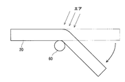
- FIG. 5 is a schematic top view showing a state in which the path regulating member 20 formed into a linear shape is formed into a final form.
- the path regulating member 20 taken out from the hot pressing mold 50 is bent and deformed at a required position by applying a force in the bending direction.
- the bending shape can be accurately formed by bending the path regulating member 20 while pressing the outer peripheral portion of the jig 60 formed in a cylindrical shape.
- the jig 60 may be deformed only by the manual work of the operator without using the jig 60.
- the final form of the path regulating member 20 is manufactured.
- the wire harness 30 is attached to the upper surface of the path regulating member 20.
- the wire harness wiring structure 10 is formed by integrating the path
- the path regulating member 20 that is hot-pressed and formed in a substantially linear shape can be easily deformed into a desired shape until it is cooled to a predetermined temperature. Therefore, if a non-woven fabric is employed as the material of the path regulating member, it is not necessary to prepare a molding die corresponding to the shape, and the manufacturing cost of the wire harness routing structure can be suppressed. However, a mold (cold mold) (not shown) may be cooled and cured while being deformed into a required shape.
- the path regulating member 20 may be manufactured using a hot press mold that forms a non-woven fabric into a non-linear shape from the beginning instead of the hot press mold 50. In this case, it is necessary to design and start a hot press mold according to the shape of the path regulating member 20. However, by using such a hot press mold, the same shape of the path regulating member 20 can be produced.
- the path regulating member 20 does not necessarily have a bent portion. That is, the non-woven fabric may be formed in a substantially linear shape with the hot pressing mold 50 and then cured as it is to be used as a route regulating member in the final form.
- the path regulating member 20 Since the path regulating member 20 according to the present embodiment is formed of a nonwoven fabric, the length can be easily adjusted by cutting with a tool such as scissors or a cutter knife. Therefore, when actually routing the wire harness 30 in the vehicle, the path regulating member 20 having a different length can be easily manufactured. Accordingly, since it is necessary to prepare all the path regulating members having different lengths, it becomes easy to manage parts at the vehicle manufacturing site.
- the resin rod for path regulation as disclosed in Patent Document 1 is difficult to be molded into an arbitrary shape. Therefore, the resin rod is hardly used for the purpose of regulating the bending of the wire harness 30. Instead, bending is regulated by a plate-like regulating member attached to the clamp member, a hard tube, or a protector.
- a plate-like regulating member attached to the clamp member, a hard tube, or a protector.
- the number of parts increases according to the type of the routing route, and a molding die for forming a bent shape is required.
- route control member Therefore The increase in a number of parts is not caused and bending is also easy.
- the path regulating member 20 is formed of a nonwoven fabric, it is relatively easy to separate the path regulating member 20 and the wire harness 30. Therefore, even when the routing route of the wire harness 30 is changed according to the design change, the wire harness 30 can be easily detached from the route restriction member 20 and attached to another new route restriction member 20. .
- the path regulating member 20 is arranged at the upper part (or the lower part) instead of wrapping the wire harness 30 like a tube. Therefore, even if the cross-sectional size of the wire harness 30 changes to some extent, the route restriction member 20 can be used as it is without changing the design.
Landscapes
- Engineering & Computer Science (AREA)
- Mechanical Engineering (AREA)
- Architecture (AREA)
- Civil Engineering (AREA)
- Structural Engineering (AREA)
- Details Of Indoor Wiring (AREA)
- Insulated Conductors (AREA)
Abstract
本願は、ワイヤーハーネスを配索するワイヤーハーネス配索構造に関する。ワイヤーハーネス配索構造は、ワイヤーハーネスと、不織布をホットプレスすることにより形成されており、前記ワイヤーハーネスに対してその延在方向に沿って取り付けられることにより、前記ワイヤーハーネスの配索経路を規制する経路規制部材とを備える。経路規制部材が不織布によって形成されることによって、周囲の部材に接触したときに発生する異音を抑えることができる。したがって、ワイヤーハーネス配索構造の静音性を向上させることができる。
Description
本発明は、車両に配索されるワイヤーハーネスの配索構造に関する。
車両に配索されるワイヤーハーネスには、その配索経路を規制するために経路規制部材が取り付けられる場合がある。例えば特許文献1では、ワイヤーハーネスを構成する電線群の外周に、まっすぐに延びる樹脂棒がワイヤーハーネスの軸線方向と平行に当てがわれている。そして、樹脂棒とワイヤーハーネスとをテープ巻きして一体化している。この樹脂棒の剛性により、ワイヤーハーネスを所定の方向に規制したり、または、ワイヤーハーネスが意図しない方向に屈曲されたりすることを抑制したりしている。
ところが、従来のように樹脂棒でワイヤーハーネスを規制した場合、樹脂棒が周囲の部材と接触するなどして、異音が発生する虞があった。そのため、樹脂棒が一部でも露出しないようにする消音テープ(アセテートやテサテープなど)等で巻き付ける必要があり、煩雑となっていた。
そこで本発明は、静音性に優れたワイヤーハーネス規制構造を簡便に実現する技術を提供することを目的とする。
上記の課題を解決するため、第1の態様は、ワイヤーハーネスを配索するワイヤーハーネス配索構造であって、ワイヤーハーネスと、不織布をホットプレスすることにより形成されており、前記ワイヤーハーネスとともに結束されることによって、前記ワイヤーハーネスの配索経路を規制する経路規制部材とを備える。
また、第2の態様は、第1の態様に係るワイヤーハーネス配索構造において、前記経路規制部材は、前記ワイヤーハーネスの延在方向に沿って延びるベース部分と、前記ベース部分の外周部分において前記ベース部分の延在方向に沿って設けられ、前記ベース部分よりも柔軟に形成されている柔軟部分とを有する。
また、第3の態様は、第1または2の態様に係るワイヤーハーネス配索構造であって、前記柔軟部分が、前記ベース部分の両側に設けられている。
また、第4の態様は、第1から第3の態様までのいずれか1態様に係るワイヤーハーネス配索構造であって、前記経路規制部材が、曲がりながら延在する部分を含む。
また、第5の態様は、ワイヤーハーネスを配索させるワイヤーハーネス配索構造の製造方法であって、(a)不織布をホットプレスすることにより、不織布を所要形状に成形する工程と、(b)前記(a)工程にて成形された不織布を変形させながら冷却することによって、経路規制部材を成形する工程と、(c)前記(b)工程にて成形された前記経路規制部材に、前記ワイヤーハーネスを取り付ける工程とを含む。
また、第6の態様は、第5の態様に係るワイヤーハーネス配索構造の製造方法において、前記(a)工程において、前記不織布の端部においてホットプレスされない部分が設定されている。
第1から第4の態様に係る経路規制部材によると、不織布によって形成されることによって、周囲の部材に接触したときに発生する異音を抑えることができる。したがって、ワイヤーハーネス配索構造の静音性を向上させることができる。
第2の態様に係るワイヤーハーネス配索構造によると、ベース部分より柔軟な柔軟部分がベース部分の端部に形成されていることにより、柔軟部分が周囲の部材と接触しても異音の発生が抑えられる。したがって、ワイヤーハーネス配索構造の静音性を向上させることができる。
第3の態様に係るワイヤーハーネス配索構造によると、ベース部の両側に柔軟部分を設けることで、ベース部分の両側に関して、周囲の部材との接触による異音の発生を抑えることができる。
第4の態様に係るワイヤーハーネス配索構造によると、ワイヤーハーネスを曲げるように経路規制することができる。また経路規制部材を不織布によって形成することにより、曲がり構造を容易に製造することができる。
第5の態様に係るワイヤーハーネス配索構造の製造方法によると、不織布を用いることによって、冷却する際に所望の形状に変形させることができる。したがって、ワイヤーハーネスの様々な配索パターンに対応したワイヤーハーネス配索構造を容易に製造することができる。
第6の態様に係るワイヤーハーネス配索構造の製造方法によると、不織布の端部の柔軟性を向上することができる。したがって、静音性に優れたワイヤーハーネス配索構造を製造することができる。
以下、実施形態に係る線状体保護部材について説明する。ただし、この実施の形態に記載されている構成はあくまでも例示であり、本発明の範囲をそれらのみに限定する趣旨のものではない。
{1. 実施形態}
<ワイヤーハーネス配索構造>
図1は、実施形態に係るワイヤーハーネス配索構造10の概略斜視図である。また図2は、図1に示したII-II線断面図である。
<ワイヤーハーネス配索構造>
図1は、実施形態に係るワイヤーハーネス配索構造10の概略斜視図である。また図2は、図1に示したII-II線断面図である。
ワイヤーハーネス配索構造10は、ワイヤーハーネス30と、ワイヤーハーネス30に取り付けられる経路規制部材20とで構成されている。ワイヤーハーネス配索構造10は、ワイヤーハーネス30を所要の方向に延びるように配索するための構造体である。
ワイヤーハーネス30としては、車両等において各種電気機器間を相互接続する電線や光ファイバーケーブル等の線状体が想定される。本願の経路規制部材20に取り付けられるワイヤーハーネス30は、1本の線状体であってもよいし、複数の線状体で構成されていてもよい。
経路規制部材20は、不織布をホットプレスすることにより形成されている。ワイヤーハーネス30が経路規制部材20に取り付けられることによって、ワイヤーハーネス30の配索経路が規制される。
不織布としては、加熱工程を経ることにより硬くなることが可能な不織布を用いることができる。このような不織布として、相互に絡み合う基本繊維と、接着樹脂(バインダとも呼ばれる)とを含むものを用いることができる。接着樹脂は、基本繊維の融点よりも低い融点(例えば、摂氏110度~115度)を有する樹脂である。このような不織布を、基本繊維の融点よりも低くかつ接着樹脂の融点よりも高い加工温度に加熱することで、接着樹脂が溶融して基本繊維間に染みこむ。その後、不織布が接着樹脂の融点よりも低い温度になると、基本繊維同士を結合した状態で接着樹脂が固化する。これより、不織布が加熱前の状態よりも硬くなり、加熱時の成形形状に維持されるようになる。
接着樹脂は、粒状であっても繊維状であってもよい。芯繊維の外周に接着樹脂層を形成してバインダ繊維を構成し、これを基本繊維と絡み合わせるようにしてもよい。この場合の芯繊維としては、上記基本繊維と同材料のものを用いることができる。
上記基本繊維としては、接着樹脂の融点で繊維状態を保ち得ればよく、樹脂繊維の他、各種繊維を用いることができる。また、接着樹脂としては、基本繊維の融点よりも低い融点を持つ熱可塑性樹脂繊維を用いることができる。基本繊維と接着樹脂の組合わせとしては、基本繊維をPET(ポリエチレンテレフタレート)の樹脂繊維とし、接着樹脂をPETとPEI(ポリエチレンイソフタレート)の共重合樹脂とした例が挙げられる。この場合、基本繊維の融点はおよそ摂氏250度であり、接着樹脂の融点は、およそ摂氏110度~150度である。このため、不織布を摂氏110度~250度の温度に加熱すると、接着樹脂が溶融し、溶融せずに繊維状を保つ基本繊維間に染込む。そして、不織布が接着樹脂の融点よりも低い温度になると、基本繊維同士を結合した状態で接着樹脂が固化し、不織布は硬くなって加熱時の成形形状を維持する。
また、ホットプレスとは、加工対象物である不織布を金型間に挟み込み、加熱状態で金型に圧を加えて不織布を成型加工することをいう。本実施形態に係る経路規制部材20を製造するのに適したホットプレス加工の例については後にさらに詳述する。
図1に示したように、経路規制部材20は、途中で曲げられている。このため、ワイヤーハーネス30を経路規制部材20に沿って取り付けた際には、ワイヤーハーネス30をその経路規制部材20に沿って曲がりながら配索される。経路規制部材20の曲げ方向は、水平面内のものに限定されるものではなく、垂直方向を含む任意の方向とすることができる。また、経路規制部材20は、1箇所のみにおいて曲げられていてもよいし、複数箇所において曲げられていてもよい。
経路規制部材20は、その延在方向に沿って上面が扁平となっている扁平部分21(ベース部分)を有している。扁平部分21の上面は、ワイヤーハーネス30を載置する載置面を形成している。扁平部分21にワイヤーハーネス30が載置された状態で、経路規制部材20とワイヤーハーネス30とが、テープ巻き等により一体化される。このとき、経路規制部材20の一部が外部に露出していたとしても、経路規制部材20は緩衝性に優れているため、他の部材との接触による異音の発生はほとんど抑えられている。したがって、経路規制部材20を完全に覆うようにテープ巻きする必要がない。また、環状のバンド部材や接着剤などで、経路規制部材20とワイヤーハーネス30とを一体化するようにしてもよい。
扁平部分21のうち、ワイヤーハーネス30を載置する載置部分にワイヤーハーネス30の形状に対応した凹部を設けて、該凹部にワイヤーハーネス30を設置できるようにしてもよい。この場合、ワイヤーハーネス30を経路規制部材20に固定しやすくなる。また、経路規制部材20の下側(突起部23が形成されていない側)に、ワイヤーハーネス30が取り付けられるようにしてもよい。
扁平部分21の上側(ワイヤーハーネス30載せられる部分)の両端部には、経路規制部材20の延在方向に沿って、上方に突出する突起部23,23が設けられている。本実施形態では、両側の突起部23,23に挟まれる位置に、ワイヤーハーネス30が設置されている。
突起部23は、扁平部分21よりも柔軟性を有するように形成されている。本実施形態では、後述するホットプレス用成形型50で不織布をホットプレスすることにより、突起部23が最も柔軟に形成されている。このように本実施形態では、突起部23は柔軟部分となっている。また、経路規制部材20の両端部分(突起部23を除く部分。)が、突起部23の次に柔軟性を有するように形成されている。そして扁平部分21は、少なくとも突起部23及び経路規制部材20の両端部分よりも硬くなるように形成されている。
このように経路規制部材20の突起部23,23や両端部分が柔軟に形成されていることによって、経路規制部材20が車両に取り付けられた際に、経路規制部材20が周囲の部材と衝突しても、異音の発生が抑えられる。このようなワイヤーハーネス配索構造10を使用することにより、車両内の静音化を図ることができる。
なお、図1,2において二点破線で示したように、経路規制部材20の下部に、クランプ構造40が取り付けられていてもよい。クランプ構造40は、図示を省略する車両に形成された孔等に対して嵌合されることにより、クランプ構造40に取り付けられたワイヤーハーネス配索構造10を固定する部材である。このようなクランプ構造40と経路規制部材20とを組み合わせることによって、ワイヤーハーネス30を車両内の所要位置に固定することができる。
<ワイヤーハーネス配索構造の製造方法>
次に、ワイヤーハーネス配索構造の製造方法について説明する。
次に、ワイヤーハーネス配索構造の製造方法について説明する。
上記経路規制部材20は、(a)不織布をホットプレスすることにより略直線状に成形する工程と、(b)ホットプレスした不織布を冷やしながら変形させる工程とにより製造することができる。そして(c)経路規制部材20にワイヤーハーネス30が取り付けられることで、ワイヤーハーネス配索構造10を製造することができる。
図3は経路規制部材20を製造するためのホットプレス用成形型50の例を示す概略斜視図である。また、図4は、ホットプレス用成形型50の概略断面図である。ホットプレス用成形型50は、下型51と、該下型51に組み合わされる上型53とで構成される。以下の説明においては、ホットプレス用成形型50において、下型51が配置される側を下側、上型53が配置される側を上側として説明する。
下型51及び上型53は、熱伝導性に優れた金属等により形成された長尺部材である。下型51の一主面(上面)には、長手方向に沿って直線状に延びるとともに、上方に開口する略直方体状の溝511(凹部)が形成されている。上型53の一主面(下面)には、下型51の前記直方体状の溝511に嵌め込まれる凸部531が長手方向に沿って形成されている。この凸部531の幅方向(長手方向に直交する方向)両端の角部分は、長手方向に沿って略直方体状の切り欠き54が形成されることによって階段状を呈している。
上記下型51及び上型53には、加熱装置としてのヒータ(図示せず。)が設けられる。ヒータは、下型51と上型53のうち不織布と接触する部分を、基本繊維の融点よりも低くかつ接着樹脂の融点よりも高い温度に加熱するものである。ヒータは、下型51及び上型53内に埋設されたものであってもよいし、下型51及び上型53に熱伝達可能な態様で取り付けられたものであってもよい。
ホットプレス用成形型50において、経路規制部材20を形成する場合、まず、下型51の溝511に不織布(経路規制部材20)が設置され、下型51の溝511に上型53の凸部531が装着される。そして、下型51と上型53との間に圧が加えられる。これにより、下型51の溝511内において、不織布に上型53の凸部531が押し当てられる。この凸部531に押し当てられる部分が、最終形態の経路規制部材20における扁平部分21に相当する。また、凸部531の幅方向両側の角部分が階段状に形成されていることにより、上型53と不織布との間に、ホットプレス用成形型50の長手方向に沿って隙間55が形成される(図4)。つまり、経路規制部材20の幅方向両端部分に上型53によって押圧されない非押圧部分(すなわち、ホットプレスされない部分)ができる。
この非押圧部分は、不織布のうち凸部531が押し当てられている部分よりも、加熱され難い部分となっている。したがって、この非押圧部分では、接着樹脂が十分に加熱され難いために、基本繊維間に接着樹脂が染み込み難くなっている。よって、加熱された不織布が冷却されて硬化したとき、この非押圧部分は、不織布本来の柔軟性をある程度保ったまま、若干の膨らむように形成されることとなる。その結果、最終形態の経路規制部材20において、突起部23を形成することとなる。
また、この非押圧部分の周辺部は、下型51の溝511の側面や底面に接しているものの、上からの押圧されていない。そのため、非押圧部分よりも加熱されやすいものの、凸部531に押圧される部分よりも、加熱され難くなっている。よって、完成形態における経路規制部材20の幅方向の両端部は、中央部の扁平部分21よりも柔軟に形成されることとなる。
次に、ホットプレス用成形型50によるホットプレスが完了すると、上型53が下型から取り外され、略直線状に成形された経路規制部材20が取り出される。なお、経路規制部材20の取り出し時期については、経路規制部材20を構成する不織布の接着樹脂が少なくとも完全に硬化する前(つまり、融点温度以下に冷却される前)とされる。このような状態の経路規制部材20は、まだ完全に硬化する前であるため、例えば作業者の手作業により容易に変形することができる程度の硬さとなっている。
図5は、直線状に成形された経路規制部材20を最終形態に成形する様子を示す概略上面図である。ホットプレス用成形型50から取り出された経路規制部材20は、曲げ方向に力がかけられることにより、所要の位置で曲げ変形される。このとき、例えば円筒状に形成された治具60の外周部分を押し当てながら、経路規制部材20を曲げることによって、曲げ形状を精度よく形成することができる。もちろん、治具60を用いずに、作業者の手作業のみで変形するようにしてもよい。また、この作業時に、例えば、室温または室温以下のエアを経路規制部材20に当ててやることで、接着樹脂の硬化を促進するようにしてもよい。以上のようにして、最終形態の経路規制部材20が製造される。
十分に冷却が行われた後、経路規制部材20の上面には、ワイヤーハーネス30が取り付けられる。そして、テープやバンド部材または接着剤等によって、経路規制部材20とワイヤーハーネス30とが一体化されることにより、ワイヤーハーネス配索構造10が形成される。
以上のように、ホットプレスされて略直線状に形成された経路規制部材20は、所定温度に冷却されるまでの間、所望の形状に容易に変形させることが可能である。したがって、経路規制部材の素材として不織布を採用すれば、形状に応じた成形用の金型を用意する必要がなくなるため、ワイヤーハーネス配索構造の製造コストを抑制することができる。ただし、図示しない成形型(コールド成形型)を用いて、所要形状に変形させながら冷却して、硬化させるようにしてもよい。
また、ホットプレス用成形型50の代わりに、不織布を始めから非直線状の所要形状に成形するホットプレス用成形型を用いて、経路規制部材20を製造するようにしてもよい。この場合、経路規制部材20の形状に応じてホットプレス用成形型を設計し、起工する必要がある。しかしながら、このようなホットプレス用成形型を用いることで、同形状の経路規制部材20を均一に製造することができる。
また、経路規制部材20は、必ずしも曲がる部分を有している必要はない。すなわち、ホットプレス用成形型50で不織布を略直線状に形成し、それをそのまま硬化させて最終形態の経路規制部材として使用してもよい。
本実施形態に係る経路規制部材20は、不織布で形成されているため、ハサミやカッターナイフなどの工具で切断することで、容易に長さを調節することができる。したがって、実際に車両にワイヤーハーネス30を配索する際に、長さの異なる経路規制部材20を容易に製作することができる。したがって、長さの異なる経路規制部材を全て用意する必要がなるため、車両の製造現場における部品管理が容易になる。
また、特許文献1に開示されているような経路規制用の樹脂棒は、任意の形状に成形することが困難であった。そのため、ワイヤーハーネス30の曲げ規制する目的では、樹脂棒がほとんど使用されていない。その代わりに、クランプ部材に取り付けられた板状の規制部材や、硬質チューブまたはプロテクターによって曲げ規制することが行われている。しかしながら、いずれの場合においても、配索経路の種類に応じて部品点数が多くなり、また、曲げ形状を形成するための成形型等が必要となる。これに対して、本実施形態では、不織布をホットプレスしたものを経路規制部材として採用するため、部品点数の増大を招くことはなく、また、曲げ加工も容易となっている。
また、経路規制部材20は不織布で形成されているため、経路規制部材20とワイヤーハーネス30とを分離することは比較的簡単である。したがって、設計変更に応じてワイヤーハーネス30の配索経路を変更するような場合においても、ワイヤーハーネス30を経路規制部材20から取り外して、別の新たな経路規制部材20に取り付けることも容易である。
また、本実実施形態に係る経路規制部材20は、ワイヤーハーネス30をチューブのように包むのではなく、上部(または下部)に配置するものである。したがって、ワイヤーハーネス30の断面の大きさがある程度変化したとしても、経路規制部材20を設計変更することなく、そのまま流用することが可能である。
{2. 変形例}
以上、実施形態について説明してきたが、本発明は上記のようなものに限定されるものではなく、様々な変形が可能である。
以上、実施形態について説明してきたが、本発明は上記のようなものに限定されるものではなく、様々な変形が可能である。
例えば、上記実施形態では、ホットプレスする際に、不織布の両端部分の上面部分だけが上型53に接触しないようにして、ホットプレスされないようにしている(図4)。しかしながら、両端部分の側面または下面が下型51に接触しないようにホットプレス用成形型50を設計することにより、経路規制部材20の幅方向端部を柔軟に形成することができる。
さらに上記実施形態および変形例にて説明した各構成は、互いに矛盾の生じない限り、適宜組み合わせたり、または省略したりすることができる。
10 ワイヤーハーネス配索構造
20 経路規制部材
21 扁平部分
23 突起部
30 ワイヤーハーネス
40 クランプ構造
50 ホットプレス用成形型
51 下型
511 溝
53 上型
531 凸部
54 切り欠き
55 隙間
60 治具
20 経路規制部材
21 扁平部分
23 突起部
30 ワイヤーハーネス
40 クランプ構造
50 ホットプレス用成形型
51 下型
511 溝
53 上型
531 凸部
54 切り欠き
55 隙間
60 治具
Claims (6)
- ワイヤーハーネスを配索するワイヤーハーネス配索構造であって、
ワイヤーハーネスと、
不織布をホットプレスすることにより形成されており、前記ワイヤーハーネスとともに結束されることによって、前記ワイヤーハーネスの配索経路を規制する経路規制部材と、
を備えるワイヤーハーネス配索構造。 - 請求項1に記載のワイヤーハーネス配索構造において、
前記経路規制部材は、
前記ワイヤーハーネスの延在方向に沿って延びるベース部分と、
前記ベース部分の外周部分において前記ベース部分の延在方向に沿って設けられ、前記ベース部分よりも柔軟に形成されている柔軟部分と、
を有するワイヤーハーネス配索構造。 - 請求項1または2に記載のワイヤーハーネス配索構造であって、
前記柔軟部分が、前記ベース部分の両側に設けられているワイヤーハーネス配索構造。 - 請求項1から3までのいずれか1項に記載のワイヤーハーネス配索構造であって、
前記経路規制部材が、曲がりながら延在する部分を含むワイヤーハーネス配索構造。 - ワイヤーハーネスを配索させるワイヤーハーネス配索構造の製造方法であって、
(a)不織布をホットプレスすることにより、不織布を所要形状に成形する工程と、
(b)前記(a)工程にて成形された不織布を変形させながら冷却することによって、経路規制部材を成形する工程と、
(c)前記(b)工程にて成形された前記経路規制部材に、前記ワイヤーハーネスを取り付ける工程と、
を含むワイヤーハーネス配索構造の製造方法。 - 請求項5に記載のワイヤーハーネス配索構造の製造方法において、
前記(a)工程において、前記不織布の端部においてホットプレスされない部分が設定されているワイヤーハーネス配索構造の製造方法。
Applications Claiming Priority (2)
| Application Number | Priority Date | Filing Date | Title |
|---|---|---|---|
| JP2011120212A JP5803283B2 (ja) | 2011-05-30 | 2011-05-30 | ワイヤーハーネス配索構造及びその製造方法 |
| JP2011-120212 | 2011-05-30 |
Publications (1)
| Publication Number | Publication Date |
|---|---|
| WO2012164771A1 true WO2012164771A1 (ja) | 2012-12-06 |
Family
ID=47258653
Family Applications (1)
| Application Number | Title | Priority Date | Filing Date |
|---|---|---|---|
| PCT/JP2011/075539 Ceased WO2012164771A1 (ja) | 2011-05-30 | 2011-11-07 | ワイヤーハーネス配索構造及びその製造方法 |
Country Status (2)
| Country | Link |
|---|---|
| JP (1) | JP5803283B2 (ja) |
| WO (1) | WO2012164771A1 (ja) |
Cited By (1)
| Publication number | Priority date | Publication date | Assignee | Title |
|---|---|---|---|---|
| US20220388462A1 (en) * | 2019-12-20 | 2022-12-08 | Autonetworks Technologies, Ltd. | Wiring member |
Families Citing this family (1)
| Publication number | Priority date | Publication date | Assignee | Title |
|---|---|---|---|---|
| JP7363465B2 (ja) * | 2019-12-24 | 2023-10-18 | 株式会社オートネットワーク技術研究所 | 配索部材及びワイヤハーネス |
Citations (5)
| Publication number | Priority date | Publication date | Assignee | Title |
|---|---|---|---|---|
| JPS544381A (en) * | 1977-06-13 | 1979-01-13 | Kojima Press Kogyo Kk | Formed wire harness and method of making same |
| JP2003197038A (ja) * | 2001-12-27 | 2003-07-11 | Yazaki Corp | ワイヤハーネス及びその製造方法 |
| JP2006010059A (ja) * | 2004-05-25 | 2006-01-12 | Mirai Ind Co Ltd | 管類又はケーブル類の保持具及び該保持具を構成する取着体 |
| JP2010027242A (ja) * | 2008-07-15 | 2010-02-04 | Yazaki Corp | ワイヤハーネス |
| JP2010184593A (ja) * | 2009-02-12 | 2010-08-26 | Nissan Motor Co Ltd | スライドドア用ハーネスの配索構造 |
-
2011
- 2011-05-30 JP JP2011120212A patent/JP5803283B2/ja not_active Expired - Fee Related
- 2011-11-07 WO PCT/JP2011/075539 patent/WO2012164771A1/ja not_active Ceased
Patent Citations (5)
| Publication number | Priority date | Publication date | Assignee | Title |
|---|---|---|---|---|
| JPS544381A (en) * | 1977-06-13 | 1979-01-13 | Kojima Press Kogyo Kk | Formed wire harness and method of making same |
| JP2003197038A (ja) * | 2001-12-27 | 2003-07-11 | Yazaki Corp | ワイヤハーネス及びその製造方法 |
| JP2006010059A (ja) * | 2004-05-25 | 2006-01-12 | Mirai Ind Co Ltd | 管類又はケーブル類の保持具及び該保持具を構成する取着体 |
| JP2010027242A (ja) * | 2008-07-15 | 2010-02-04 | Yazaki Corp | ワイヤハーネス |
| JP2010184593A (ja) * | 2009-02-12 | 2010-08-26 | Nissan Motor Co Ltd | スライドドア用ハーネスの配索構造 |
Cited By (2)
| Publication number | Priority date | Publication date | Assignee | Title |
|---|---|---|---|---|
| US20220388462A1 (en) * | 2019-12-20 | 2022-12-08 | Autonetworks Technologies, Ltd. | Wiring member |
| US12128835B2 (en) * | 2019-12-20 | 2024-10-29 | Autonetworks Technologies, Ltd. | Wiring member with route bending |
Also Published As
| Publication number | Publication date |
|---|---|
| JP5803283B2 (ja) | 2015-11-04 |
| JP2012248459A (ja) | 2012-12-13 |
Similar Documents
| Publication | Publication Date | Title |
|---|---|---|
| JP5891868B2 (ja) | ワイヤーハーネスの製造方法及びワイヤーハーネス | |
| JP5772798B2 (ja) | ワイヤーハーネス及びワイヤーハーネスの製造方法 | |
| JP5353801B2 (ja) | 電線保護具 | |
| JP5807477B2 (ja) | ワイヤーハーネス | |
| JP5895614B2 (ja) | ワイヤーハーネス及びワイヤーハーネスの製造方法 | |
| CN103890861B (zh) | 线束以及线束的制造方法 | |
| JP5660001B2 (ja) | ワイヤーハーネス及びワイヤーハーネスの製造方法 | |
| JP5768702B2 (ja) | ワイヤーハーネス | |
| JP5359922B2 (ja) | 保護部材付電線 | |
| JP5803283B2 (ja) | ワイヤーハーネス配索構造及びその製造方法 | |
| JP5803557B2 (ja) | ワイヤーハーネス | |
| JP5768634B2 (ja) | ワイヤーハーネスの製造方法及びワイヤーハーネス | |
| JP5630343B2 (ja) | ワイヤハーネス | |
| JP2014003757A (ja) | 経路維持保護部材及びワイヤーハーネス | |
| JP2013150406A (ja) | ワイヤーハーネス | |
| JP2012183927A (ja) | 電線保護具及びワイヤハーネス | |
| JP6015572B2 (ja) | 保護部材付ワイヤーハーネスの製造方法及びホットプレス用成形金型装置 | |
| JP5966975B2 (ja) | ホットプレス用成形型及びワイヤーハーネスの製造方法 | |
| JP5772239B2 (ja) | 線状体保護部材 | |
| JP6079429B2 (ja) | ワイヤーハーネス及びワイヤーハーネスの製造方法 | |
| JP2013058438A (ja) | ワイヤーハーネス及びその製造方法 | |
| JP2014230422A (ja) | ワイヤーハーネス | |
| JP5614374B2 (ja) | 被覆部材付電線束及び被覆部材付電線束の製造方法 | |
| JP2014140262A (ja) | 保護部材付ワイヤーハーネス |
Legal Events
| Date | Code | Title | Description |
|---|---|---|---|
| 121 | Ep: the epo has been informed by wipo that ep was designated in this application |
Ref document number: 11866751 Country of ref document: EP Kind code of ref document: A1 |
|
| NENP | Non-entry into the national phase |
Ref country code: DE |
|
| 122 | Ep: pct application non-entry in european phase |
Ref document number: 11866751 Country of ref document: EP Kind code of ref document: A1 |