WO2012161303A1 - ガスバリア性複合フィルム、及びこれを用いた真空断熱材 - Google Patents
ガスバリア性複合フィルム、及びこれを用いた真空断熱材 Download PDFInfo
- Publication number
- WO2012161303A1 WO2012161303A1 PCT/JP2012/063431 JP2012063431W WO2012161303A1 WO 2012161303 A1 WO2012161303 A1 WO 2012161303A1 JP 2012063431 W JP2012063431 W JP 2012063431W WO 2012161303 A1 WO2012161303 A1 WO 2012161303A1
- Authority
- WO
- WIPO (PCT)
- Prior art keywords
- gas barrier
- heat insulating
- insulating material
- hot water
- vacuum heat
- Prior art date
- Legal status (The legal status is an assumption and is not a legal conclusion. Google has not performed a legal analysis and makes no representation as to the accuracy of the status listed.)
- Ceased
Links
Images



Classifications
-
- F—MECHANICAL ENGINEERING; LIGHTING; HEATING; WEAPONS; BLASTING
- F16—ENGINEERING ELEMENTS AND UNITS; GENERAL MEASURES FOR PRODUCING AND MAINTAINING EFFECTIVE FUNCTIONING OF MACHINES OR INSTALLATIONS; THERMAL INSULATION IN GENERAL
- F16L—PIPES; JOINTS OR FITTINGS FOR PIPES; SUPPORTS FOR PIPES, CABLES OR PROTECTIVE TUBING; MEANS FOR THERMAL INSULATION IN GENERAL
- F16L59/00—Thermal insulation in general
- F16L59/06—Arrangements using an air layer or vacuum
-
- B—PERFORMING OPERATIONS; TRANSPORTING
- B32—LAYERED PRODUCTS
- B32B—LAYERED PRODUCTS, i.e. PRODUCTS BUILT-UP OF STRATA OF FLAT OR NON-FLAT, e.g. CELLULAR OR HONEYCOMB, FORM
- B32B27/00—Layered products comprising a layer of synthetic resin
- B32B27/06—Layered products comprising a layer of synthetic resin as the main or only constituent of a layer, which is next to another layer of the same or of a different material
-
- B—PERFORMING OPERATIONS; TRANSPORTING
- B32—LAYERED PRODUCTS
- B32B—LAYERED PRODUCTS, i.e. PRODUCTS BUILT-UP OF STRATA OF FLAT OR NON-FLAT, e.g. CELLULAR OR HONEYCOMB, FORM
- B32B2307/00—Properties of the layers or laminate
- B32B2307/70—Other properties
- B32B2307/724—Permeability to gases, adsorption
- B32B2307/7242—Non-permeable
- B32B2307/7244—Oxygen barrier
Definitions
- the present invention relates to a gas barrier composite film and a vacuum heat insulating material using the same, and more particularly to a gas barrier composite film used for a vacuum heat insulating material that can be used even in places exposed to high temperatures, and a vacuum heat insulating material using the same.
- Styrofoam is widely used as a heat insulating material such as a tank of a natural refrigerant heat pump water heater. Styrofoam is excellent in that it is low in cost and easily available, but has a problem of poor heat insulation.
- a vacuum heat insulating material with extremely high heat insulating properties is used in refrigerators, freezers, and the like for the purpose of reducing power consumption by heat insulation. The vacuum heat insulating material is reduced in heat conduction by air due to the reduced pressure inside. For this reason, a vacuum heat insulating material has extremely high heat insulation compared with a polystyrene foam etc.
- the vacuum heat insulating material mainly includes a core material such as fiber, foam, or porous powder, and a gas barrier outer bag covering the core material.
- the gas barrier outer bag has a role of blocking air and maintaining a vacuum therein, while the core member has a role of supporting the space inside the outer bag.
- the gas barrier outer bag is usually formed by heat-sealing the peripheral portions of a pair of gas barrier composite films. For this reason, the gas barrier composite film has a heat-sealing layer.
- a polyethylene film is widely used as such a heat-sealing layer.
- a vacuum heat insulating material which has a polyethylene film as a heat sealing
- a vacuum heat insulating material is used as a heat insulating material, a significant reduction in power consumption can be expected.
- the vacuum heat insulating material having a polyethylene film cannot be used in a place exposed to a high temperature such as a tank of a natural refrigerant heat pump water heater due to the low heat resistance of the polyethylene film.
- a polypropylene film has higher heat resistance than a polyethylene film, but a vacuum heat insulating material using a gas barrier composite film having this as a heat-fusible layer has not yet been put into practical use.
- the present invention provides a vacuum heat insulating material that can be used even in places exposed to high temperatures, and uses a gas barrier composite film that enables this, particularly a polypropylene film, as a heat fusion layer.
- An object is to provide a gas barrier composite film.
- a gas barrier composite film using a polypropylene film as a heat-sealing layer has been put to practical use as an outer bag material of a vacuum heat insulating material that can also be used in places exposed to high temperatures.
- the reason why it was not possible is not clear.
- high heat insulation was realized when a vacuum heat insulating material manufactured using a polypropylene film as a heat-sealing layer of a gas barrier composite film was used in a place exposed to high temperatures. I could't.
- Item 1 Containing a gas barrier layer and a polypropylene film layer, A gas barrier composite film having a volatile gas amount of 6 mg / m 2 or less.
- Item 2. The gas barrier composite film according to Item 1, wherein the total amount of methanol and ethanol is 5 mg / m 2 or less.
- Item 3. Item 3.
- Item 4. Item 4. The gas barrier composite film according to any one of Items 1 to 3, wherein the polypropylene film layer comprises a polypropylene film having a volatile gas amount of 0.02 mg / g or less.
- Item 5. The gas barrier composite film according to any one of Items 1 to 4, wherein the gas barrier layer and the heat fusion layer are bonded to each other by an adhesive layer.
- Item 6. The gas barrier composite film according to Item 5, wherein the adhesive layer is formed of an epoxy-modified urethane adhesive.
- Item 7. The gas barrier composite film according to any one of Items 1 to 6, which is an outer bag material of a vacuum heat insulating material.
- Item 8. An outer bag comprising the gas barrier composite film according to any one of Items 1 to 7 and a core material enclosed in the outer bag, A vacuum heat insulating material in which the inside of the outer bag is depressurized.
- a hot water heater provided with a hot water storage tank for storing heated hot water for hot water supply
- a hot water heater wherein a surface of the hot water storage tank is covered with the vacuum heat insulating material according to Item 8.
- Item 10 In a cup-type vending machine comprising a hot water storage tank for storing heated hot water for beverages, and pouring and selling the hot beverage obtained from the hot water supplied from the hot water storage tank and the raw material of the beverage, A cup-type vending machine, wherein the surface of the hot water storage tank is covered with the vacuum heat insulating material according to Item 8.
- Item 11 In a cup-type vending machine comprising a hot water storage tank for storing heated hot water for beverages, and pouring and selling the hot beverage obtained from the hot water supplied from the hot water storage tank and the raw material of the beverage, A cup-type vending machine, wherein the surface of the hot water storage tank is covered with the vacuum heat insulating material according to Item 8.
- a product storage device comprising a storage for storing products, and storing the products in the storage in a refrigerated state and / or a refrigerated state
- the inner surface of each frame plate constituting at least five surfaces excluding the front surface of the storage is covered with the vacuum heat insulating material according to Item 8, or the frame plates are from the vacuum heat insulating material according to Item 8.
- a product storage device comprising a storage for storing products, and storing the products in the storage in a refrigerated state and / or a refrigerated state
- the storage has a plurality of product storage rooms partitioned by a partition plate, and the products can be stored in a refrigerated state or a warmed state in each of the product storage rooms
- the product storage device wherein a surface of the partition plate is covered with the vacuum heat insulating material according to Item 8, or the partition plate is made of the vacuum heat insulating material according to Item 8.
- Item 13 A vehicle air conditioner including an air conditioning unit in which a heater core is housed in a duct, wherein the vacuum heat insulating material according to item 8 is disposed between an inner surface of the duct and the heater core. Air conditioning equipment.
- the gas barrier composite film of the present invention enables the production of a vacuum heat insulating material exhibiting high heat insulating properties even when used in a place exposed to high temperatures.
- the vacuum heat insulating material of the present invention exhibits high heat insulating properties even when used in a place exposed to high temperatures.
- the gas barrier composite film of the present invention contains a gas barrier layer and a polypropylene film layer,
- the amount of volatile gas is 6 mg / m 2 or less.
- the amount of the volatile gas is preferably 5 mg / m 2 or less.
- the amount of volatile gas in the gas barrier composite film of the present invention is the total of each amount of methanol, ethanol, 2-methyl-1-pentene, methylcyclopentane, ethyl acetate, and n-heptane.
- the gas barrier composite film of the present invention preferably has a total amount of methanol and ethanol of 5 mg / m 2 or less.
- Setting the amount of volatile gas to such a value can be achieved, for example, by producing a gas barrier composite film using a material having a small amount of volatile gas, or by evaporating volatile gas. Evaporating the volatile gas can be performed during and / or after the lamination of the layers of the gas barrier composite film of the present invention.
- This “after lamination” includes every time after lamination, for example, when the film after lamination is stored, and after the film after lamination is formed into a bag having an opening (eg, a three-sided bag). .
- the volatile gas can be evaporated by leaving the laminated film.
- the laminated film may be heated for the purpose of promoting evaporation of the volatile gas. Examples of conditions for such heat treatment include conditions of 50 to 80 ° C. and 0.5 to 1.0 hour. Further, the laminated film may be placed under reduced pressure for the purpose of promoting evaporation of volatile gas.
- the amount of volatile gas of the gas barrier composite film of the present invention is measured by the following measuring method.
- the measurement method has the following steps. Step 1: Cut a gas barrier composite film 50 mm ⁇ 280 mm into small pieces of about 0.004 m 2 and enclose them in a 300 ml Erlenmeyer flask. Step 2: The Erlenmeyer flask in which the small pieces are enclosed is heated at 80 ° C. for 30 minutes to volatilize volatile components in the film. Step 3: Collect 1 ml of gas in the Erlenmeyer flask with a glass microsyringe. Step 4: The collected gas is analyzed by the headspace method by gas chromatography under the following analysis conditions.
- the gas barrier composite film of the present invention usually has a surface protective layer.
- the gas barrier composite film of the present invention has a surface protective layer, a gas barrier layer, and a polypropylene film layer in this order. Each layer is preferably adhered by an adhesive. Accordingly, an adhesive layer is preferably present between the surface protective layer and the gas barrier layer and between the gas barrier layer and the polypropylene film layer, respectively.
- FIG. 1 shows a preferred embodiment of the gas barrier composite film of the present invention.
- the illustration of the adhesive layer between the surface protective layer and the gas barrier layer is omitted.
- the gas-barrier composite film of this invention is demonstrated in detail.
- the surface protective layer 1 has a function of protecting the gas barrier layer described in detail later and / or a function of imparting mechanical strength to the gas barrier composite film of the present invention.
- the surface protective layer include polyamide resin (eg, nylon), polyolefin resin (eg, polyethylene resin, polypropylene resin), cyclic polyolefin resin, polystyrene resin, acrylonitrile-styrene copolymer (AS resin), acrylonitrile-butadiene- Styrene copolymer (ABS resin), poly (meth) acrylic resin, polycarbonate resin, polyvinyl alcohol resin, saponified ethylene-vinyl ester copolymer (EVOH resin), polyester resin (eg, polyethylene terephthalate, polyethylene naphthalate), A resin film selected from a polyurethane resin, an acetal resin, a cellulose resin, and the like can be used.
- polyamide resin eg, nylon
- polyolefin resin eg
- a polyamide resin film preferably nylon
- a polyester resin film preferably polyethylene terephthalate
- Such a film can be an unstretched film or a film stretched in a uniaxial or biaxial direction.
- the surface protective layer may have a multilayer structure (eg, a two-layer structure). When the surface protective layer has a multilayer structure, each layer may be the same resin film or a different resin film.
- the surface protective layer having such a multilayer structure can be produced by a known method such as a method of bonding each layer with an adhesive, a coextrusion method, or an extrusion laminating method.
- the surface protective layer particularly preferably has a two-layer structure composed of a polyamide resin film (preferably nylon) and a polyester resin film (preferably polyethylene terephthalate).
- the thickness of the surface protective layer is not particularly limited, but is usually about 5 to 2000 ⁇ m, preferably about 6 to 1000 ⁇ m, more preferably about 7 to 100 ⁇ m, and still more preferably about 10 to 50 ⁇ m.
- the gas barrier layer 2 has a function of blocking gas. Thereby, when the gas barrier composite film of the present invention is used as a vacuum heat insulating material, the vacuum inside the vacuum heat insulating material is maintained.
- the gas barrier layer 2 is preferably bonded to the surface protective layer 1 by an adhesive layer.
- the gas barrier layer only needs to have gas barrier properties.
- metal foil such as aluminum foil, copper foil, stainless steel foil; or metal atoms (eg, polyethylene terephthalate film) on a substrate of resin film (eg, polyethylene terephthalate film).
- Aluminum metal oxide, or a deposited film on which silicon oxide or the like is deposited can be used.
- the thickness of the gas barrier layer is not limited as long as it is a thickness capable of blocking gas, and varies depending on the material of the gas barrier layer, but for example, in the case of an aluminum foil, it is usually 5 to 10 ⁇ m.
- the polypropylene film layer 3 functions as a heat sealing layer. Therefore, the polypropylene film layer 3 is located on the surface layer of the gas barrier composite film of the present invention.
- the polypropylene film layer 3 is preferably bonded to the gas barrier layer 2 by an adhesive layer 4.
- the manufacturing method of the polypropylene resin which comprises a polypropylene film is not specifically limited, The polypropylene resin manufactured by the gaseous-phase method is preferable.
- the polypropylene resin produced by the vapor phase method is easy to control the amount of volatile gas described in detail below.
- the amount of volatile gas in the polypropylene film of the polypropylene film layer is preferably 0.02 mg / g or less, more preferably 0.015 mg / g or less, and still more preferably 0.008 mg / g or less.
- the amount of volatile gas of the polypropylene resin constituting the polypropylene film layer (or polypropylene film) is preferably 0.04 mg / g or less, more preferably 0.03 mg / g or less, and still more preferably 0.016 mg / g or less. is there.
- the amount of the volatile gas is such a value, the vacuum heat insulating material using the gas barrier composite film of the present invention for the outer bag material exhibits high heat insulating properties even when used in a place exposed to high temperatures.
- Such a polypropylene film may be prepared by selecting a polypropylene film having a small amount of volatile gas or a commercially available polypropylene resin. Alternatively, the amount of the volatile gas can be reduced by evaporation by heat-treating the polypropylene film or the polypropylene resin. Examples of conditions for such heat treatment include conditions of 50 to 80 ° C. and 0.5 to 1.0 hour. Further, a polypropylene film or a polypropylene resin may be placed under reduced pressure for the purpose of promoting evaporation of volatile gas. The amount of volatile gas of the polypropylene film or polypropylene resin is measured by the following measuring method. Alternatively, the polypropylene film may be washed with a solvent and then dried. Such a polypropylene film is also commercially available.
- Step 1 10 g of polypropylene resin pellets are sealed in a 300 ml Erlenmeyer flask.
- Step 2 The Erlenmeyer flask in which the pellet is enclosed is heated at 100 ° C. for 30 minutes to volatilize the volatile components in the pellet.
- Step 3 Collect 2 ml of gas in the Erlenmeyer flask with a glass microsyringe.
- Step 4 Analyzing the collected gas by gas chromatography (manufactured by Shimadzu Corporation, GC-14B or equivalent) by the headspace method.
- Step 1 A polypropylene film 0.2 m 2 was measured by weight, were cut into approximately 0.004 m 2 pieces, be enclosed in 300ml Erlenmeyer flask.
- Step 2 The Erlenmeyer flask in which the small pieces are enclosed is heated at 100 ° C. for 10 minutes to volatilize volatile components in the film.
- Step 3 Collect 2 ml of gas in the Erlenmeyer flask with a glass microsyringe.
- Step 4 Analyzing the collected gas by gas chromatography (manufactured by Shimadzu Corporation, GC-14B or equivalent) by the headspace method.
- the thickness of the polypropylene film layer is not limited as long as it can be heat-sealed, but is usually 30 to 80 ⁇ m.
- the gas barrier layer and the heat fusion layer are bonded to each other.
- the volatile gas contained in the adhesive layer uses the gas barrier composite film of the present invention for a vacuum heat insulating material. This is a major cause of reducing the heat insulation properties of the vacuum insulation material under high temperature conditions. Examples of such a volatile gas include methanol and ethanol.
- the gas barrier composite film of the present invention contains methanol and / or ethanol, the methanol and / or ethanol is presumed to be mainly contained in the adhesive layer.
- the total amount of methanol and ethanol in the gas barrier composite film of the present invention is preferably 5 mg / m 2 or less. Further, the total amount of methanol and ethanol in the adhesive layer between the gas barrier layer and the polypropylene film layer is preferably 2 mg / m 2 or less. When the amount is such a value, the vacuum heat insulating material using the gas barrier composite film of the present invention for the outer bag material exhibits high heat insulating properties even when used in a place exposed to high temperatures.
- the adhesive layer is preferably formed from an epoxy-modified urethane adhesive.
- the gas barrier composite film of the present invention can be produced by laminating a gas barrier layer, a polypropylene film layer, and each layer provided as desired by a known method such as adhesion with an adhesive.
- the adhesive used for the adhesive layer include an epoxy-modified urethane adhesive, a polyacrylate adhesive, a cyanoacrylate adhesive, and a silicone adhesive.
- an epoxy-modified urethane adhesive is preferably used for bonding the gas barrier layer and the polypropylene film layer.
- the solvent remaining in the adhesive layer between the gas barrier layer and the polypropylene film layer is the heat insulating property of the vacuum heat insulating material under high temperature conditions when the gas barrier composite film of the present invention is used for the vacuum heat insulating material. It becomes a big cause to lower. Therefore, in particular, in the adhesion between the gas barrier layer and the polypropylene film layer, it is preferable to reduce the solvent remaining in the adhesive layer, and it is particularly preferable to use a solventless adhesive. Accordingly, the vacuum heat insulating material using the gas barrier composite film of the present invention for the outer bag material exhibits high heat insulating properties even when used in a place exposed to high temperatures.
- the amount of the adhesive is not particularly limited as long as sufficient adhesion is possible, but it is usually used in an amount having a solid content of 1 to 3 g / m 2 .
- the gas barrier composite film of the present invention can be used as an outer bag material of a vacuum heat insulating material in the same manner as the conventional outer bag material of a vacuum heat insulating material, and the gas barrier composite film of the present invention is used for an outer bag material. Even when used in places exposed to high temperatures, the vacuum insulation material that has been used exhibits high thermal insulation properties.
- the vacuum insulation material of the present invention is The outer bag comprising the gas barrier composite film of the present invention and a core material enclosed in the outer bag, The inside of the outer bag is depressurized.
- FIG. 2 the suitable one aspect
- the present invention will be described in detail with reference to FIG.
- a pair of the gas barrier composite film 10 of the present invention is disposed so that the polypropylene film layer 3 (omitted in FIG. 2) faces each other, and the peripheral portion thereof is heat-sealed (heat seal).
- a sealed outer bag 100 is formed.
- a core member 20 is enclosed in the outer bag 100.
- the outer bag 100 where the core material 20 is present is decompressed.
- the core material 20 has a function of holding a reduced pressure space in the outer bag 100.
- the shape of the core member 20 is usually a plate shape.
- the core material that can be used include foams such as urethane foam, styrene foam, and phenol foam; fiber bodies such as glass wool, rock wool, alumina fibers, and silica alumina fibers; and porous powders such as perlite and silica. Of these, glass wool (preferably a fiber diameter of 3 to 5 ⁇ m) is preferable.
- the core material preferably has a high porosity (eg, about 90% or more).
- An adsorbent that adsorbs volatile gas or the like may be enclosed in the outer bag 100.
- Examples of such an adsorbent include activated carbon and zeolite.
- the shape and size of the vacuum heat insulating material of the present invention are the same as those of conventional vacuum heat insulating materials. Specifically, the vacuum heat insulating material of the present invention has a plate shape of, for example, 10 to 70 cm ⁇ 10 to 2 m ⁇ 1 to 5 cm.
- the vacuum heat insulating material of the present invention is a method known as a manufacturing method of a vacuum heat insulating material, specifically, for example, a pair of the gas barrier composite film 10 of the present invention is a polypropylene film layer 3 (omitted in FIG. 2). ) Are arranged so as to face each other, and the core material 20 is housed in an outer bag formed by heat-sealing the peripheral edge except for the opening, and then, under reduced pressure (preferably 1.0 ⁇ ) in a vacuum chamber. 10 ⁇ 2 to 1.0 ⁇ 10 ⁇ 4 Pa, more preferably 1.0 ⁇ 10 ⁇ 3 to 1.0 ⁇ 10 ⁇ 4 Pa), and the outer bag is sealed by heat sealing the opening. can do.
- the heat sealing may be performed using a commercially available heat sealing apparatus, and the width of the heat sealing is usually about 5 to 15 mm.
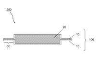
- edge 30 generated by heat sealing is used as it is, it will be a hindrance to use the vacuum heat insulating materials side by side without any gaps, so the edge 30 is usually held in a bent state.
- a pinhole may occur in the gas barrier layer.
- such a pinhole is hard to generate
- the water heater generally includes a heat pump unit 40 for heating water, a hot water storage tank 41 for storing hot water heated in the heat pump unit 40, and a bath. And a water supply 42 such as a faucet for a kitchen or a wash basin.
- the heat pump unit 40 is a known unit having a compressor, a gas cooler, an expansion valve, and an evaporator, and detailed description thereof is omitted here.
- the hot water storage tank 41 has a substantially cylindrical shape, and a water supply pipe 43 is connected to the lower part of the hot water storage tank 41.
- the water supply pipe 43 is connected to a water storage tank (not shown), and water is supplied from the water storage tank through the water supply pipe 43.
- a water intake pipe 44 is connected to the lower part of the hot water storage tank 41.
- the incoming water pipe 44 is connected to the heat pump unit 40, and the water supplied to the hot water storage tank 41 is supplied to the heat pump unit 40 via the incoming water pipe 44 and heated by the heat pump unit 40 to become hot water having a predetermined temperature.
- the hot water is supplied to the hot water storage tank 41 via the hot water supply pipe 45 and stored in the hot water storage tank 41.
- the hot water stored in the hot water storage tank 41 is supplied to the water feeder 42 via the hot water supply pipe 46
- the water heater of the present invention is characterized in that the surface of the hot water storage tank 41 is covered with the vacuum heat insulating material 200 having the above configuration, as shown in FIG. Thereby, it can insulate effectively also about what becomes high temperature like the hot water storage tank 41 of a water heater, and can prevent that the heat of the hot water storage tank 41 is radiated to external atmosphere.
- the entire surface of the hot water storage tank 41 is covered with the vacuum heat insulating material 200, but may be a part of the hot water storage tank 41, for example, only the peripheral surface of the hot water storage tank 41.
- the cup-type vending machine includes a hot water storage tank for storing hot water for beverage heated by a heating means, and the hot water storage Using hot water supplied from a tank, an arbitrary hot beverage is produced from beverage ingredients such as instant coffee powder, instant cocoa powder, and instant tea powder, and this hot beverage is poured into a cup and sold.
- the cup type vending machine of the present invention is characterized in that, in this type of cup type vending machine, the surface of the hot water storage tank for storing hot water is covered with the vacuum heat insulating material 200 having the above-described configuration. . Thereby, it can insulate effectively also about what becomes high temperature like the hot water storage tank of a cup-type vending machine, and it can prevent that the heat
- the vacuum heat insulating material of the present invention as well as the above-described hot water heater and cup type vending machine, for a device having a hot water storage tank for storing heated hot water therein, as a heat insulating material for the hot water storage tank, It can be used suitably.
- the product storage device stores products such as vending machines that sell products in paper packs, cans, bottles or plastic bottles, and showcases that can be refrigerated and stored in stores.
- the inside of the storage to be performed is partitioned by a partition plate so that the product can be stored at different temperatures (refrigerated state or refrigerated state).
- a showcase capable of refrigeration and warm storage is provided with a storage 50 for storing products, as shown in FIG.
- the storage 50 is constituted by a top frame plate 51, a bottom frame plate 52, a rear frame plate 53, and a pair of left and right side frame plates 54, and the inside thereof is partitioned into a plurality of product storage chambers by a plurality of partition plates.
- the storage 50 is divided into two product storage chambers 50A and 50B by a single partition plate 55, one product storage chamber 50A being a refrigeration chamber and the other product storage chamber 50B being a warm chamber. It is a storage room.
- the refrigerator compartment 50A and the refrigerator compartment 50B are cooled and heated by a cooling means and a heating means (not shown), respectively, and products stored inside can be stored in a refrigerated state and a refrigerated state, respectively.
- the frame plates 51 to 54 constituting the storage 50 and the partition plate 55 provided in the storage 50 are made of a heat insulating material or the surfaces of the frame plates 51 to 54 and the partition plate 55. In general, these are covered with a heat insulating material.
- the product storage device of the present invention is an apparatus capable of storing this type of product in a refrigerated state and / or a refrigerated state, in the surface of each frame plate 51 to 54 constituting the storage 50 and in the storage 50.
- the product storage 50 is divided into two product storage chambers 50A and 50B by one partition plate 55, but is not limited to this, and two or more partition plates are provided. It may be configured to be divided into three or more product storage rooms.
- the vacuum heat insulating material of the present invention is used in the storage of the showcase product.
- the product provided in the vending machine has a different temperature (refrigerated state or refrigerated state). It goes without saying that the vacuum heat insulating material of the present invention can be used in the same manner for storage cabinets that can be stored in the same manner.
- the vehicle air conditioner generally includes an evaporator 61 as a cooler, a heater core 62 as a heater, a blower 63, and a duct 60.
- An air inversion space 64 is provided.
- An air mix damper 65 is provided between the heater core 62 and the evaporator 61, and controls the amount of air that has passed through the evaporator 61 and that bypasses the heater core 62.
- Various outlets 66 to 68 are opened at positions downstream of the heater core 62.
- the air sent out by the blower 63 flows into the evaporator 61 from a partial region of the evaporator 61, passes through the evaporator 61, then flows into the wind direction reversal space 64, and along the air path indicated by the arrow in FIG. It flows again into the evaporator 61 from the other region of the evaporator 61.
- the air that has flowed in passes through the evaporator 61 and is sent downstream in either the heater core 62, the bypass, or the mixed mode of both depending on the control position of the air mix damper 65.
- the temperature-controlled air is sent to each of the outlets 66 to 68 whose opening is adjusted.
- the vehicle air conditioner according to the present invention is a vacuum having the above-described configuration between the inner surface of the duct 60 and the heater core 62 (in the illustrated example, the upper surface and the lower surface of the heater core 62).
- the heat insulating material 200 is provided. Thereby, it can heat-insulate effectively about what becomes high temperature like the heater core 62, and it can prevent that the heat
- the volatile gas content of the unstretched polypropylene film was measured by a measuring method having the following steps.
- Step 1 A polypropylene film 0.2 m 2 was measured by weight, were cut into approximately 0.004 m 2 pieces, be enclosed in 300ml Erlenmeyer flask.
- Step 2 The Erlenmeyer flask in which the small pieces are enclosed is heated at 100 ° C. for 10 minutes to volatilize volatile components in the film.
- Step 3 Collect 2 ml of gas in the Erlenmeyer flask with a glass microsyringe.
- Step 4 Analyzing the collected gas by gas chromatography (manufactured by Shimadzu Corporation, GC-14B or equivalent) by the headspace method.
- PET biaxially stretched polyethylene terephthalate film
- ONY biaxially stretched polyamide film
- an aluminum foil (Nihon Foil Co., Ltd., JIS8021) (thickness 6.5 ⁇ m) is bonded to the outer surface of the polyamide film by the same dry laminating method, and unstretched polypropylene is further bonded to the outer surface of the aluminum foil by the dry laminating method.
- a film hereinafter sometimes abbreviated as CPP) (Toyobo, Pyrene Film P1146) (thickness 50 ⁇ m) (volatile gas content 0.026 mg / g) was bonded.
- Example 1 Manufacture of composite film used for vacuum insulation panel outer bag
- PET biaxially stretched polyethylene terephthalate film
- ONY biaxially stretched polyamide film
- an aluminum foil (Nihon Foil Co., Ltd., JIS8021) (thickness 6.5 ⁇ m) is bonded to the outer surface of the polyamide film by the same dry laminating method, and unstretched polypropylene is further bonded to the outer surface of the aluminum foil by the dry laminating method.
- a film (hereinafter sometimes abbreviated as CPP) (Mitsui Chemicals, Inc., RXC11) (thickness 50 ⁇ m) (volatile gas amount 0.008 mg / g) was bonded.
- Example 2 The composite film obtained in Example 1 was allowed to stand in the atmosphere at 45 ° C. for 168 hours to obtain the composite film of Example 2. Furthermore, the vacuum heat insulation panel of Example 2 was manufactured using the said composite film.
- Example 3 The composite film obtained in Comparative Example 1 was allowed to stand in the atmosphere at 45 ° C. for 168 hours to obtain a composite film of Example 3. Furthermore, the vacuum heat insulation panel of Example 3 was manufactured using the said composite film.
- the amount of volatile gas of each composite film obtained was measured by the following measuring method.
- the measurement method has the following steps. Step 1: Cut a gas barrier composite film 50 mm ⁇ 280 mm into small pieces of about 0.004 m 2 and enclose them in a 300 ml Erlenmeyer flask. Step 2: The Erlenmeyer flask in which the small pieces are enclosed is heated at 80 ° C. for 30 minutes to volatilize volatile components in the film. Step 3: Collect 1 ml of gas in the Erlenmeyer flask with a glass microsyringe. Step 4: The collected gas is analyzed by the headspace method by gas chromatography under the following analysis conditions.
- Table 4 shows the volatile gas amounts of the composite films of Examples 1 to 3.
- the thermal conductivity at an intermediate temperature of 70 ° C. was calculated from an approximate expression created from the other three points.
- the gas barrier composite film of the present invention can be used for producing a vacuum heat insulating material exhibiting high heat insulating properties even when used in a place exposed to high temperatures.
- the vacuum heat insulating material of the present invention can be used for heat insulation in places exposed to high temperatures, such as a tank of a natural refrigerant heat pump water heater.
Landscapes
- Engineering & Computer Science (AREA)
- General Engineering & Computer Science (AREA)
- Mechanical Engineering (AREA)
- Thermal Insulation (AREA)
- Details Of Fluid Heaters (AREA)
- Laminated Bodies (AREA)
Abstract
本発明は、高温に曝される場所にも使用することができる真空断熱材を提供することを可能にする、ガスバリア性複合フィルムを提供することを目的とする。ガスバリア層、及びポリプロピレンフィルム層を含有し、揮発ガス量が6mg/m2以下であるガスバリア性複合フィルム。
Description
本発明は、ガスバリア性複合フィルム、及びこれを用いた真空断熱材、特に、高温に曝される場所でも使用できる真空断熱材に用いられるガスバリア性複合フィルム、及びこれを用いた真空断熱材に関する。
自然冷媒ヒートポンプ給湯機のタンク等の断熱材には発泡スチロールが汎用されれている。発泡スチロールは、コストが低く、かつ容易に入手できる点で優れるが、断熱性に劣るという問題がある。
一方、冷蔵庫、及び冷凍庫等には、断熱により消費電力を低減させる目的で、断熱性が極めて高い真空断熱材が用いられている。
真空断熱材は、その内部が減圧されていることにより、空気による熱伝導が低減されている。このため、真空断熱材は、発泡スチロール等に比べて極めて高い断熱性を有する。
一般的に、真空断熱材は、繊維、発泡体又は多孔性粉体等である芯材と、これを覆うガスバリア性の外袋と、から主としてなる。ガスバリア性の外袋は、空気を遮断してその内部の真空を維持する役割を有し、一方、芯材は、当該外袋内部の空間を支持する役割を有する。
ガスバリアの外袋は、通常、一対のガスバリア性複合フィルムの周縁部を熱融着させることによって形成される。このため、ガスバリア性複合フィルムは、熱融着層を有する。
このような熱融着層としては、ポリエチレンフィルムが汎用されている。
熱融着層としてポリエチレンフィルムを有する真空断熱材としては、例えば、特許文献1、2に記載の真空断熱材が挙げられる。
一方、冷蔵庫、及び冷凍庫等には、断熱により消費電力を低減させる目的で、断熱性が極めて高い真空断熱材が用いられている。
真空断熱材は、その内部が減圧されていることにより、空気による熱伝導が低減されている。このため、真空断熱材は、発泡スチロール等に比べて極めて高い断熱性を有する。
一般的に、真空断熱材は、繊維、発泡体又は多孔性粉体等である芯材と、これを覆うガスバリア性の外袋と、から主としてなる。ガスバリア性の外袋は、空気を遮断してその内部の真空を維持する役割を有し、一方、芯材は、当該外袋内部の空間を支持する役割を有する。
ガスバリアの外袋は、通常、一対のガスバリア性複合フィルムの周縁部を熱融着させることによって形成される。このため、ガスバリア性複合フィルムは、熱融着層を有する。
このような熱融着層としては、ポリエチレンフィルムが汎用されている。
熱融着層としてポリエチレンフィルムを有する真空断熱材としては、例えば、特許文献1、2に記載の真空断熱材が挙げられる。
自然冷媒ヒートポンプ給湯機のタンク等においても、断熱材として、真空断熱材を使用すれば、消費電力の大幅な低減を期待できる。しかし、ポリエチレンフィルムを有する真空断熱材は、ポリエチレンフィルムの耐熱性の低さに起因して、自然冷媒ヒートポンプ給湯機のタンクのように高温に曝される場所に使用することはできなかった。
一方、例えば、ポリプロピレンフィルムは、ポリエチレンフィルムよりも高い耐熱性を有するが、これを熱融着層として有するガスバリア性複合フィルムを用いた真空断熱材は、いまだ実用化されていない。
従って、本発明は、高温に曝される場所にも使用することができる真空断熱材を提供すること、及び、これを可能にするガスバリア性複合フィルム、特にポリプロピレンフィルムを熱融着層として用いたガスバリア性複合フィルムを提供することを目的とする。
一方、例えば、ポリプロピレンフィルムは、ポリエチレンフィルムよりも高い耐熱性を有するが、これを熱融着層として有するガスバリア性複合フィルムを用いた真空断熱材は、いまだ実用化されていない。
従って、本発明は、高温に曝される場所にも使用することができる真空断熱材を提供すること、及び、これを可能にするガスバリア性複合フィルム、特にポリプロピレンフィルムを熱融着層として用いたガスバリア性複合フィルムを提供することを目的とする。
本発明が属する技術分野において、高温に曝される場所にも使用することができる真空断熱材の外袋材として、ポリプロピレンフィルムを熱融着層として用いたガスバリア性複合フィルムが、これまで実用化できなかった理由は、定かではない。しかし、本発明者らのこれまでの試行では、ポリプロピレンフィルムをガスバリア性複合フィルムの熱融着層として用いて製造した真空断熱材を高温に曝される場所に使用した場合、高い断熱性を実現することができなかった。このことが、ポリプロピレンフィルムを熱融着層として用いたガスバリア性複合フィルムが、これまで真空断熱材の外袋材として実用化できなかったことの、大きな原因であると考えられる。
しかし、本発明者らにとっても、ポリプロピレンフィルムを熱融着層として用いて製造した真空断熱材を高温に曝される場所に使用した場合、高い断熱性を実現することができない原因は、明らかではなかった。
本発明者らは、鋭意研究の結果、真空断熱材の含有する揮発ガスがその原因であることを突き止め、この揮発ガス量(揮発成分量)を低いレベルに制御することによって、高温に曝される場所に使用した場合でも、高い断熱性を示す真空断熱材を製造できることを見出し、更なる研究の結果、本発明を完成するに至った。
しかし、本発明者らにとっても、ポリプロピレンフィルムを熱融着層として用いて製造した真空断熱材を高温に曝される場所に使用した場合、高い断熱性を実現することができない原因は、明らかではなかった。
本発明者らは、鋭意研究の結果、真空断熱材の含有する揮発ガスがその原因であることを突き止め、この揮発ガス量(揮発成分量)を低いレベルに制御することによって、高温に曝される場所に使用した場合でも、高い断熱性を示す真空断熱材を製造できることを見出し、更なる研究の結果、本発明を完成するに至った。
すなわち、本発明は、以下の各項に記載の側面を有する。
項1.
ガスバリア層、及びポリプロピレンフィルム層を含有し、
揮発ガス量が6mg/m2以下である
ガスバリア性複合フィルム。
項2.
メタノール量とエタノール量の合計が5mg/m2以下である項1に記載のガスバリア性複合フィルム。
項3.
前記ポリプロピレンフィルム層が、気相法で製造されたポリプロピレン樹脂から構成されるポリプロピレンフィルム層である項1又は2に記載のガスバリア性複合フィルム。
項4.
前記ポリプロピレンフィルム層が、揮発ガス量が0.02mg/g以下であるポリプロピレンフィルムからなる項1~3のいずれか1項に記載のガスバリア性複合フィルム。
項5.
ガスバリア層、及び熱融着層が、接着剤層によって互いに接着されている項1~4のいずれか1項に記載のガスバリア性複合フィルム。
項6.
前記接着剤層が、エポキシ変性ウレタン接着剤から形成されている項5に記載のガスバリア性複合フィルム。
項7.
真空断熱材の外袋材である項1~6のいずれか1項に記載のガスバリア性複合フィルム。
項8.
項1~7のいずれか1項に記載のガスバリア性複合フィルムからなる外袋と
前記外袋内に封入された芯材
とを備え、
前記外袋内部が減圧されている
真空断熱材。
項9.
給湯用の加熱された温水を貯留する貯湯タンクを備える給湯器において、
前記貯湯タンクの表面が項8に記載の真空断熱材により覆われていることを特徴とする給湯器。
項10.
飲料用の加熱された温水を貯留する貯湯タンクを備え、前記貯湯タンクから供給される温水と飲料の原料とにより得られる温飲料をカップへ注いで販売するカップ式自動販売機において、
前記貯湯タンクの表面が項8に記載の真空断熱材により覆われていることを特徴とするカップ式自動販売機。
項11.
商品を収納する収納庫を備え、前記収納庫内の商品を冷蔵状態および/または温蔵状態で保存する商品収納装置において、
前記収納庫の少なくとも前面を除く5面を構成する各枠板の内側面が項8に記載の真空断熱材により覆われている、または、前記各枠板が項8に記載の真空断熱材よりなることを特徴とする商品収納装置。
項12.
商品を収納する収納庫を備え、前記収納庫内の商品を冷蔵状態および/または温蔵状態で保存する商品収納装置において、
前記収納庫は、仕切板により区画された複数の商品収納室を有し、前記各商品収納室において商品を冷蔵状態または温蔵状態で保存可能であり、
前記仕切板の表面が項8に記載の真空断熱材により覆われている、または、前記仕切板が項8に記載の真空断熱材よりなることを特徴とする商品収納装置。
項13.
ダクト内にヒータコアを収納した空調ユニットを備える車両用空気調和装置において、前記ダクトの内面と前記ヒータコアとの間に、項8に記載の真空断熱材が配設されていることを特徴とする車両用空気調和装置。
ガスバリア層、及びポリプロピレンフィルム層を含有し、
揮発ガス量が6mg/m2以下である
ガスバリア性複合フィルム。
項2.
メタノール量とエタノール量の合計が5mg/m2以下である項1に記載のガスバリア性複合フィルム。
項3.
前記ポリプロピレンフィルム層が、気相法で製造されたポリプロピレン樹脂から構成されるポリプロピレンフィルム層である項1又は2に記載のガスバリア性複合フィルム。
項4.
前記ポリプロピレンフィルム層が、揮発ガス量が0.02mg/g以下であるポリプロピレンフィルムからなる項1~3のいずれか1項に記載のガスバリア性複合フィルム。
項5.
ガスバリア層、及び熱融着層が、接着剤層によって互いに接着されている項1~4のいずれか1項に記載のガスバリア性複合フィルム。
項6.
前記接着剤層が、エポキシ変性ウレタン接着剤から形成されている項5に記載のガスバリア性複合フィルム。
項7.
真空断熱材の外袋材である項1~6のいずれか1項に記載のガスバリア性複合フィルム。
項8.
項1~7のいずれか1項に記載のガスバリア性複合フィルムからなる外袋と
前記外袋内に封入された芯材
とを備え、
前記外袋内部が減圧されている
真空断熱材。
項9.
給湯用の加熱された温水を貯留する貯湯タンクを備える給湯器において、
前記貯湯タンクの表面が項8に記載の真空断熱材により覆われていることを特徴とする給湯器。
項10.
飲料用の加熱された温水を貯留する貯湯タンクを備え、前記貯湯タンクから供給される温水と飲料の原料とにより得られる温飲料をカップへ注いで販売するカップ式自動販売機において、
前記貯湯タンクの表面が項8に記載の真空断熱材により覆われていることを特徴とするカップ式自動販売機。
項11.
商品を収納する収納庫を備え、前記収納庫内の商品を冷蔵状態および/または温蔵状態で保存する商品収納装置において、
前記収納庫の少なくとも前面を除く5面を構成する各枠板の内側面が項8に記載の真空断熱材により覆われている、または、前記各枠板が項8に記載の真空断熱材よりなることを特徴とする商品収納装置。
項12.
商品を収納する収納庫を備え、前記収納庫内の商品を冷蔵状態および/または温蔵状態で保存する商品収納装置において、
前記収納庫は、仕切板により区画された複数の商品収納室を有し、前記各商品収納室において商品を冷蔵状態または温蔵状態で保存可能であり、
前記仕切板の表面が項8に記載の真空断熱材により覆われている、または、前記仕切板が項8に記載の真空断熱材よりなることを特徴とする商品収納装置。
項13.
ダクト内にヒータコアを収納した空調ユニットを備える車両用空気調和装置において、前記ダクトの内面と前記ヒータコアとの間に、項8に記載の真空断熱材が配設されていることを特徴とする車両用空気調和装置。
本発明のガスバリア性複合フィルムは、高温に曝される場所に使用された場合でも高い断熱性を示す真空断熱材の製造を可能にする。
本発明の真空断熱材は、高温に曝される場所に使用された場合でも高い断熱性を示す。
本発明の真空断熱材は、高温に曝される場所に使用された場合でも高い断熱性を示す。
以下に、添付図面を参照して本発明の実施形態を説明する。
これらの図面において同一の部材には同一の参照符号が付けられている。なお、これらの図面では縮尺を適宜変更している。
本発明の理解を容易にするために添付図面の参照符号を付記する場合があるが、本発明は、図示された態様に限定されるものではない。
これらの図面において同一の部材には同一の参照符号が付けられている。なお、これらの図面では縮尺を適宜変更している。
本発明の理解を容易にするために添付図面の参照符号を付記する場合があるが、本発明は、図示された態様に限定されるものではない。
1.ガスバリア性複合フィルム
本発明のガスバリア性複合フィルムは、ガスバリア層、及びポリプロピレンフィルム層を含有し、
揮発ガス量が6mg/m2以下である。
当該揮発ガス量は、好ましくは5mg/m2以下である。
揮発ガス量が6mg/m2以下である。
当該揮発ガス量は、好ましくは5mg/m2以下である。
本発明のガスバリア性複合フィルムの揮発ガス量は、メタノール、エタノール、2-メチル-1-ペンテン、メチルシクロペンタン、酢酸エチル、及びn-ヘプタンの各量の合計である。
本発明のガスバリア性複合フィルムは、好ましくは、メタノール量とエタノール量の合計が5mg/m2以下である。
当該揮発ガス量(特に、メタノール量とエタノール量の合計)がこのような値であることにより、本発明のガスバリア性複合フィルムを外袋材に用いた真空断熱材は、高温に曝される場所に使用した場合でも、高い断熱性を示す。
本発明のガスバリア性複合フィルムは、好ましくは、メタノール量とエタノール量の合計が5mg/m2以下である。
当該揮発ガス量(特に、メタノール量とエタノール量の合計)がこのような値であることにより、本発明のガスバリア性複合フィルムを外袋材に用いた真空断熱材は、高温に曝される場所に使用した場合でも、高い断熱性を示す。
当該揮発ガス量をこのような値にすることは、例えば、当該揮発ガス量が少ない材料を用いてガスバリア性複合フィルムを製造すること、又は、揮発ガスを蒸発させることによって達成できる。揮発ガスを蒸発させることは、本発明のガスバリア性複合フィルムが有する各層の積層時、及び/又は積層後に実施することができる。この「積層後」には、積層後のあらゆる時点、例えば、積層後のフィルムの保管時、及び積層後のフィルムを開口部を有する袋(例、3方袋)に成形した後等が含まれる。揮発ガスを蒸発させることは、積層後のフィルムを放置することによって実施できる。
この場合、揮発ガスの蒸発を促進する目的で、積層後のフィルムを加熱してもよい。
このような加熱処理の条件としては、例えば、50~80℃、及び0.5~1.0時間の条件が挙げられる。
また、揮発ガスの蒸発を促進する目的で、積層後のフィルムを減圧下に置いてもよい。
この場合、揮発ガスの蒸発を促進する目的で、積層後のフィルムを加熱してもよい。
このような加熱処理の条件としては、例えば、50~80℃、及び0.5~1.0時間の条件が挙げられる。
また、揮発ガスの蒸発を促進する目的で、積層後のフィルムを減圧下に置いてもよい。
本発明のガスバリア性複合フィルムの揮発ガス量は、次の測定方法によって測定される。
(測定方法)
当該測定方法は、次の段階を有する。
段階1:ガスバリア性複合フィルム50mm×280mmを、約0.004m2の小片に切断し、300ml三角フラスコに封入すること。
段階2:前記小片が封入された三角フラスコを、80℃で30分加熱して、フィルム内の揮発成分を揮発させること。
段階3:三角フラスコ内の気体1mlをガラス製マイクロシリンジにて採取すること。
段階4:採取した気体を下記分析条件のガスクロマトグラフィーにてヘッドスペース法で分析すること。
<分析条件>
<分析条件> 三角フラスコ保温温度:80℃
三角フラスコ保温時間:30分
注入量:1mL
カラム:PEG-20M 20% on Chromosorb-W(AW-DMCS),80/100mesh,(3m×2.6mm) glass
カラム温度:80℃
カラム流量:N2 20mL/min
(測定方法)
当該測定方法は、次の段階を有する。
段階1:ガスバリア性複合フィルム50mm×280mmを、約0.004m2の小片に切断し、300ml三角フラスコに封入すること。
段階2:前記小片が封入された三角フラスコを、80℃で30分加熱して、フィルム内の揮発成分を揮発させること。
段階3:三角フラスコ内の気体1mlをガラス製マイクロシリンジにて採取すること。
段階4:採取した気体を下記分析条件のガスクロマトグラフィーにてヘッドスペース法で分析すること。
<分析条件>
<分析条件> 三角フラスコ保温温度:80℃
三角フラスコ保温時間:30分
注入量:1mL
カラム:PEG-20M 20% on Chromosorb-W(AW-DMCS),80/100mesh,(3m×2.6mm) glass
カラム温度:80℃
カラム流量:N2 20mL/min
また、本発明のガスバリア性複合フィルムは、通常、表面保護層を有する。
本発明のガスバリア性複合フィルムは、表面保護層、ガスバリア層、及びポリプロピレンフィルム層を、この記載の順で、有する。
各層は、好ましくは、接着剤によって接着されている。従って、表面保護層とガスバリア層との間、並びにガスバリア層とポリプロピレンフィルム層との間には、それぞれ、好ましくは、接着剤層が存在する。
本発明のガスバリア性複合フィルムは、表面保護層、ガスバリア層、及びポリプロピレンフィルム層を、この記載の順で、有する。
各層は、好ましくは、接着剤によって接着されている。従って、表面保護層とガスバリア層との間、並びにガスバリア層とポリプロピレンフィルム層との間には、それぞれ、好ましくは、接着剤層が存在する。
本発明のガスバリア性複合フィルムの揮発ガス量において、前述の断熱性に深く関係するのは、主に、真空断熱材においてガスバリア層より内側に位置することになるポリプロピレンフィルム層及び接着剤層が含有する揮発ガスの量であり、特に接着剤層が含有する揮発ガスの量である。
図1に、本発明のガスバリア性複合フィルムの好適な一態様を示す。図1では、表面保護層とガスバリア層との間の接着剤層の図示を省略している。
以下に、図1を参照して、本発明のガスバリア性複合フィルムを詳細に説明する。
図1に、本発明のガスバリア性複合フィルムの好適な一態様を示す。図1では、表面保護層とガスバリア層との間の接着剤層の図示を省略している。
以下に、図1を参照して、本発明のガスバリア性複合フィルムを詳細に説明する。
1.1.表面保護層
表面保護層1は、後記で詳細に説明するガスバリア層を保護する機能、及び/又は本発明のガスバリア性複合フィルムに機械的強度を付与する機能を有する。
表面保護層としては、例えば、ポリアミド樹脂(例、ナイロン)、ポリオレフィン樹脂(例、ポリエチレン樹脂、ポリプロピレン樹脂)、環状ポリオレフィン樹脂、ポリスチレン樹脂、アクリロニトリル-スチレン共重合体(AS樹脂)、アクリロニトリル-ブタジエン-スチレン共重合体(ABS樹脂)、ポリ(メタ)アクリル樹脂、ポリカーボネート樹脂、ポリビニルアルコール樹脂、エチレン-ビニルエステル共重合体ケン化物(EVOH樹脂)、ポリエステル樹脂(例、ポリエチレンテレフタレート、ポリエチレンナフタレート)、ポリウレタン樹脂、アセタール樹脂、及びセルロース系樹脂等から選択される樹脂のフィルムを使用することができる。
なかでも、ポリアミド樹脂フィルム(好ましくは、ナイロン)、及びポリエステル樹脂フィルム(好ましくは、ポリエチレンテレフタレート)が好ましい。
このようなフィルムは、未延伸フィルム、又は一軸方向もしくは二軸方向に延伸したフィルムであることができる。
表面保護層は、多層構造(例、2層構造)を有していてもよい。表面保護層が多層構造を有する場合、各層は、同一の樹脂フィルムであってもよく、異なる樹脂フィルムであってもよい。
このような多層構造を有する表面保護層は、例えば、各層を接着剤によって接着する方法、共押出法、又は押出しラミネート法などの公知の方法によって製造できる。
表面保護層は、特に好ましくは、ポリアミド樹脂フィルム(好ましくは、ナイロン)、及びポリエステル樹脂フィルム(好ましくは、ポリエチレンテレフタレート)からなる2層構造である。
表面保護層の厚さは、特に限定されないが、通常5~2000μm程度、好ましくは6~1000μm程度、より好ましくは7~100μm程度、更に好ましくは10~50μm程度である。
表面保護層1は、後記で詳細に説明するガスバリア層を保護する機能、及び/又は本発明のガスバリア性複合フィルムに機械的強度を付与する機能を有する。
表面保護層としては、例えば、ポリアミド樹脂(例、ナイロン)、ポリオレフィン樹脂(例、ポリエチレン樹脂、ポリプロピレン樹脂)、環状ポリオレフィン樹脂、ポリスチレン樹脂、アクリロニトリル-スチレン共重合体(AS樹脂)、アクリロニトリル-ブタジエン-スチレン共重合体(ABS樹脂)、ポリ(メタ)アクリル樹脂、ポリカーボネート樹脂、ポリビニルアルコール樹脂、エチレン-ビニルエステル共重合体ケン化物(EVOH樹脂)、ポリエステル樹脂(例、ポリエチレンテレフタレート、ポリエチレンナフタレート)、ポリウレタン樹脂、アセタール樹脂、及びセルロース系樹脂等から選択される樹脂のフィルムを使用することができる。
なかでも、ポリアミド樹脂フィルム(好ましくは、ナイロン)、及びポリエステル樹脂フィルム(好ましくは、ポリエチレンテレフタレート)が好ましい。
このようなフィルムは、未延伸フィルム、又は一軸方向もしくは二軸方向に延伸したフィルムであることができる。
表面保護層は、多層構造(例、2層構造)を有していてもよい。表面保護層が多層構造を有する場合、各層は、同一の樹脂フィルムであってもよく、異なる樹脂フィルムであってもよい。
このような多層構造を有する表面保護層は、例えば、各層を接着剤によって接着する方法、共押出法、又は押出しラミネート法などの公知の方法によって製造できる。
表面保護層は、特に好ましくは、ポリアミド樹脂フィルム(好ましくは、ナイロン)、及びポリエステル樹脂フィルム(好ましくは、ポリエチレンテレフタレート)からなる2層構造である。
表面保護層の厚さは、特に限定されないが、通常5~2000μm程度、好ましくは6~1000μm程度、より好ましくは7~100μm程度、更に好ましくは10~50μm程度である。
1.2.ガスバリア層
ガスバリア層2は、気体を遮断する機能を有する。これによって、本発明のガスバリア性複合フィルムを真空断熱材に用いる場合、真空断熱材内部の真空が維持される。
ガスバリア層2は、好ましくは、接着剤層によって、表面保護層1に接着されている。
ガスバリア層としては、ガスバリア性を有するものであればよく、例えば、アルミニウム箔、銅箔、ステンレス箔などの金属箔;又は樹脂フィルム(例、ポリエチレンテレフタレートフィルム)の基材上に金属原子(例、アルミニウム)、金属酸化物、又は酸化ケイ素等を蒸着させた蒸着フィルム等を使用できる。
ガスバリア層の厚さは、気体を遮断できる厚さであれば限定されず、ガスバリア層の材質等によって異なるが、例えば、アルミニウム箔の場合、通常、5~10μmである。
ガスバリア層2は、気体を遮断する機能を有する。これによって、本発明のガスバリア性複合フィルムを真空断熱材に用いる場合、真空断熱材内部の真空が維持される。
ガスバリア層2は、好ましくは、接着剤層によって、表面保護層1に接着されている。
ガスバリア層としては、ガスバリア性を有するものであればよく、例えば、アルミニウム箔、銅箔、ステンレス箔などの金属箔;又は樹脂フィルム(例、ポリエチレンテレフタレートフィルム)の基材上に金属原子(例、アルミニウム)、金属酸化物、又は酸化ケイ素等を蒸着させた蒸着フィルム等を使用できる。
ガスバリア層の厚さは、気体を遮断できる厚さであれば限定されず、ガスバリア層の材質等によって異なるが、例えば、アルミニウム箔の場合、通常、5~10μmである。
1.3.ポリプロピレンフィルム層
ポリプロピレンフィルム層3は、熱融着層として機能する。
従って、ポリプロピレンフィルム層3は、本発明のガスバリア性複合フィルムの表層に位置する。
ポリプロピレンフィルム層3は、好ましくは、接着剤層4によって、ガスバリア層2に接着されている。
ポリプロピレンフィルムを構成するポリプロピレン樹脂の製造方法は、特に限定されないが、気相法で製造されたポリプロピレン樹脂が好ましい。気相法で製造されたポリプロピレン樹脂は、下記で詳細に説明する揮発ガス量を制御し易い。
ポリプロピレンフィルム層3は、熱融着層として機能する。
従って、ポリプロピレンフィルム層3は、本発明のガスバリア性複合フィルムの表層に位置する。
ポリプロピレンフィルム層3は、好ましくは、接着剤層4によって、ガスバリア層2に接着されている。
ポリプロピレンフィルムを構成するポリプロピレン樹脂の製造方法は、特に限定されないが、気相法で製造されたポリプロピレン樹脂が好ましい。気相法で製造されたポリプロピレン樹脂は、下記で詳細に説明する揮発ガス量を制御し易い。
ポリプロピレンフィルム層のポリプロピレンフィルムの揮発ガス量は、好ましくは0.02mg/g以下、より好ましくは0.015mg/g以下、更に好ましくは0.008mg/g以下である。
また、ポリプロピレンフィルム層(又はポリプロピレンフィルム)を構成するポリプロピレン樹脂の揮発ガス量は、好ましくは0.04mg/g以下、より好ましくは0.03mg/g以下、更に好ましくは0.016mg/g以下である。
当該揮発ガス量がこのような値であることにより、本発明のガスバリア性複合フィルムを外袋材に用いた真空断熱材は、高温に曝される場所に使用した場合でも、高い断熱性を示す。
このようなポリプロピレンフィルムは、揮発ガス量が小さいポリプロピレンフィルム又はポリプロピレン樹脂の市販品を選択することによって準備すればよい。
あるいは、ポリプロピレンフィルム又はポリプロピレン樹脂を加熱処理することによって、当該揮発ガス量を蒸発によって減少させることができる。
このような加熱処理の条件としては、例えば、50~80℃、及び0.5~1.0時間の条件が挙げられる。
また、揮発ガスの蒸発を促進する目的で、ポリプロピレンフィルム又はポリプロピレン樹脂をを減圧下に置いてもよい。
前記ポリプロピレンフィルム又はポリプロピレン樹脂の揮発ガス量は、次の測定方法によって測定される。
あるいは、ポリプロピレンフィルムを溶媒で洗浄後、乾燥してもよい。このようなポリプロピレンフィルムは、市販品でも入手可能である。
また、ポリプロピレンフィルム層(又はポリプロピレンフィルム)を構成するポリプロピレン樹脂の揮発ガス量は、好ましくは0.04mg/g以下、より好ましくは0.03mg/g以下、更に好ましくは0.016mg/g以下である。
当該揮発ガス量がこのような値であることにより、本発明のガスバリア性複合フィルムを外袋材に用いた真空断熱材は、高温に曝される場所に使用した場合でも、高い断熱性を示す。
このようなポリプロピレンフィルムは、揮発ガス量が小さいポリプロピレンフィルム又はポリプロピレン樹脂の市販品を選択することによって準備すればよい。
あるいは、ポリプロピレンフィルム又はポリプロピレン樹脂を加熱処理することによって、当該揮発ガス量を蒸発によって減少させることができる。
このような加熱処理の条件としては、例えば、50~80℃、及び0.5~1.0時間の条件が挙げられる。
また、揮発ガスの蒸発を促進する目的で、ポリプロピレンフィルム又はポリプロピレン樹脂をを減圧下に置いてもよい。
前記ポリプロピレンフィルム又はポリプロピレン樹脂の揮発ガス量は、次の測定方法によって測定される。
あるいは、ポリプロピレンフィルムを溶媒で洗浄後、乾燥してもよい。このようなポリプロピレンフィルムは、市販品でも入手可能である。
(測定方法:ポリプロピレン樹脂ペレット)
当該測定方法は、次の段階を有する。
段階1:ポリプロピレン樹脂ペレット10gを、300ml三角フラスコに封入する。
段階2:前記ペレットが封入された三角フラスコを、100℃で30分加熱して、ペレット内の揮発成分を揮発させること。
段階3:三角フラスコ内の気体2mlをガラス製マイクロシリンジにて採取すること。
段階4:採取した気体をガスクロマトグラフィー(島津製作所製、GC-14B又はその同等品)にてヘッドスペース法で分析すること。
当該測定方法は、次の段階を有する。
段階1:ポリプロピレン樹脂ペレット10gを、300ml三角フラスコに封入する。
段階2:前記ペレットが封入された三角フラスコを、100℃で30分加熱して、ペレット内の揮発成分を揮発させること。
段階3:三角フラスコ内の気体2mlをガラス製マイクロシリンジにて採取すること。
段階4:採取した気体をガスクロマトグラフィー(島津製作所製、GC-14B又はその同等品)にてヘッドスペース法で分析すること。
(測定方法:ポリプロピレンフィルム)
当該測定方法は、次の段階を有する。
段階1:質量を測定したポリプロピレンフィルム0.2m2を、約0.004m2の小片に切断し、300ml三角フラスコに封入すること。
段階2:前記小片が封入された三角フラスコを、100℃で10分加熱して、フィルム内の揮発成分を揮発させること。
段階3:三角フラスコ内の気体2mlをガラス製マイクロシリンジにて採取すること。
段階4:採取した気体をガスクロマトグラフィー(島津製作所製、GC-14B又はその同等品)にてヘッドスペース法で分析すること。
当該測定方法は、次の段階を有する。
段階1:質量を測定したポリプロピレンフィルム0.2m2を、約0.004m2の小片に切断し、300ml三角フラスコに封入すること。
段階2:前記小片が封入された三角フラスコを、100℃で10分加熱して、フィルム内の揮発成分を揮発させること。
段階3:三角フラスコ内の気体2mlをガラス製マイクロシリンジにて採取すること。
段階4:採取した気体をガスクロマトグラフィー(島津製作所製、GC-14B又はその同等品)にてヘッドスペース法で分析すること。
ポリプロピレンフィルム層の厚さは、ヒートシールが可能な厚さであれば限定されないが、通常、30~80μmである。
1.4.接着剤層
接着剤層4は、ガスバリア層、及び熱融着層を互いに接着させている。
本発明のガスバリア性複合フィルムが、ガスバリア層とポリプロピレンフィルム層との間に接着剤層を有する場合、当該接着剤層が含有する揮発ガスは、本発明のガスバリア性複合フィルムを真空断熱材に用いた真空断熱材の高温条件下での断熱性を低下させる大きな原因となる。
このような揮発ガスとしては、例えば、メタノール、及びエタノールが挙げられる。本発明のガスバリア性複合フィルムがメタノール及び/又はエタノールを含有する場合、当該メタノール及び/又はエタノールは主として接着剤層が含有するものであると推定される。
前述のように、本発明のガスバリア性複合フィルムのメタノール量とエタノール量の合計は、好ましくは5mg/m2以下である。また、ガスバリア層とポリプロピレンフィルム層との間の接着剤層のメタノール量とエタノール量の合計は、好ましくは2mg/m2以下である。
当該量がこのような値であることにより、本発明のガスバリア性複合フィルムを外袋材に用いた真空断熱材は、高温に曝される場所に使用した場合でも、高い断熱性を示す。
接着剤層は、好ましくは、エポキシ変性ウレタン接着剤から形成されている。
接着剤層4は、ガスバリア層、及び熱融着層を互いに接着させている。
本発明のガスバリア性複合フィルムが、ガスバリア層とポリプロピレンフィルム層との間に接着剤層を有する場合、当該接着剤層が含有する揮発ガスは、本発明のガスバリア性複合フィルムを真空断熱材に用いた真空断熱材の高温条件下での断熱性を低下させる大きな原因となる。
このような揮発ガスとしては、例えば、メタノール、及びエタノールが挙げられる。本発明のガスバリア性複合フィルムがメタノール及び/又はエタノールを含有する場合、当該メタノール及び/又はエタノールは主として接着剤層が含有するものであると推定される。
前述のように、本発明のガスバリア性複合フィルムのメタノール量とエタノール量の合計は、好ましくは5mg/m2以下である。また、ガスバリア層とポリプロピレンフィルム層との間の接着剤層のメタノール量とエタノール量の合計は、好ましくは2mg/m2以下である。
当該量がこのような値であることにより、本発明のガスバリア性複合フィルムを外袋材に用いた真空断熱材は、高温に曝される場所に使用した場合でも、高い断熱性を示す。
接着剤層は、好ましくは、エポキシ変性ウレタン接着剤から形成されている。
1.5.製造方法
本発明のガスバリア性複合フィルムは、ガスバリア層、ポリプロピレンフィルム層、及び所望により設けられる各層を、接着剤による接着等の公知の方法で積層することによって、製造することができる。
接着剤層に用いられる接着剤としては、エポキシ変性ウレタン接着剤、ポリアクリル酸エステル接着剤、シアノアクリレート接着剤、シリコーン接着剤等が挙げられる。
特に、ガスバリア層とポリプロピレンフィルム層との接着には、エポキシ変性ウレタン接着剤を用いることが好ましい。
前述のように、ガスバリア層とポリプロピレンフィルム層との間の接着剤層に残存する溶剤は、本発明のガスバリア性複合フィルムを真空断熱材に用いる場合、高温条件下での真空断熱材の断熱性を低下させる大きな原因となる。
従って、特に、ガスバリア層とポリプロピレンフィルム層との接着においては、接着剤層に残存する溶剤が少なくなるようにすることが好ましく、無溶剤型の接着剤を使用することが特に好ましい。
これらによって、本発明のガスバリア性複合フィルムを外袋材に用いた真空断熱材は、高温に曝される場所に使用した場合でも、高い断熱性を示す。
接着剤の量は、十分な接着ができる限り特に限定されないが、通常、固形分が1~3g/m2である量で使用する。
本発明のガスバリア性複合フィルムは、ガスバリア層、ポリプロピレンフィルム層、及び所望により設けられる各層を、接着剤による接着等の公知の方法で積層することによって、製造することができる。
接着剤層に用いられる接着剤としては、エポキシ変性ウレタン接着剤、ポリアクリル酸エステル接着剤、シアノアクリレート接着剤、シリコーン接着剤等が挙げられる。
特に、ガスバリア層とポリプロピレンフィルム層との接着には、エポキシ変性ウレタン接着剤を用いることが好ましい。
前述のように、ガスバリア層とポリプロピレンフィルム層との間の接着剤層に残存する溶剤は、本発明のガスバリア性複合フィルムを真空断熱材に用いる場合、高温条件下での真空断熱材の断熱性を低下させる大きな原因となる。
従って、特に、ガスバリア層とポリプロピレンフィルム層との接着においては、接着剤層に残存する溶剤が少なくなるようにすることが好ましく、無溶剤型の接着剤を使用することが特に好ましい。
これらによって、本発明のガスバリア性複合フィルムを外袋材に用いた真空断熱材は、高温に曝される場所に使用した場合でも、高い断熱性を示す。
接着剤の量は、十分な接着ができる限り特に限定されないが、通常、固形分が1~3g/m2である量で使用する。
本発明のガスバリア性複合フィルムは、真空断熱材の外袋材として、従来の真空断熱材の外袋材と同様の方法で用いることができ、本発明のガスバリア性複合フィルムを外袋材に用いた真空断熱材は、高温に曝される場所に使用した場合でも、高い断熱性を示す。
2.真空断熱材
本発明の真空断熱材は、
本発明のガスバリア性複合フィルムからなる外袋と
前記外袋内に封入された芯材
とを備え、
前記外袋内部が減圧されている。
本発明の真空断熱材は、
本発明のガスバリア性複合フィルムからなる外袋と
前記外袋内に封入された芯材
とを備え、
前記外袋内部が減圧されている。
図2に、本発明の真空断熱材の好適な一態様を示す。
以下に、図2を参照して、本発明を詳細に説明する。
以下に、図2を参照して、本発明を詳細に説明する。
真空断熱材200において、本発明のガスバリア性複合フィルム10の一対は、ポリプロピレンフィルム層3(図2では省略されている)が対向するように配置され、その周縁部が熱融着(ヒートシール)されて、密封された外袋100を形成している。
外袋100内には、芯材20が封入されている。
芯材20が存在する外袋100外袋内部は、減圧されている。
外袋100内には、芯材20が封入されている。
芯材20が存在する外袋100外袋内部は、減圧されている。
芯材20は、外袋100内の減圧空間を保持する機能を有する。
芯材20の形状は、通常、板状である。
芯材としては、例えば、ウレタンフォーム、スチレンフォーム、フェノールフォームなどの気泡体;グラスウール、ロックウール、アルミナ繊維、シリカアルミナ繊維などの繊維体;パーライト、シリカなどの多孔性粉体などを使用できる。なかでも、グラスウール(好ましくは、繊維径3~5μm)が好ましい。芯材は、高い空隙率(例、約90%以上)を有することが好ましい。
芯材20の形状は、通常、板状である。
芯材としては、例えば、ウレタンフォーム、スチレンフォーム、フェノールフォームなどの気泡体;グラスウール、ロックウール、アルミナ繊維、シリカアルミナ繊維などの繊維体;パーライト、シリカなどの多孔性粉体などを使用できる。なかでも、グラスウール(好ましくは、繊維径3~5μm)が好ましい。芯材は、高い空隙率(例、約90%以上)を有することが好ましい。
外袋100の内部には、揮発ガス等を吸着する吸着剤が封入されていてもよい。このような吸着剤としては、例えば、活性炭、ゼオライト等が挙げられる。
本発明の真空断熱材の形状及びサイズは、従来の真空断熱材と同様である。本発明の真空断熱材は、具体的には、例えば、10~70cm×10~2m×1~5cmの板状である。
本発明の真空断熱材は、真空断熱材の製造方法として公知の方法、具体的には、例えば、本発明のガスバリア性複合フィルム10の一対を、ポリプロピレンフィルム層3(図2では省略されている)が対向するように配置し、開口部を除いて周縁部をヒートシールして形成した外袋に、芯材20を収納し、その後、真空チャンバー内で、減圧下(好ましくは1.0×10⁻²~1.0×10⁻⁴Pa、より好ましくは1.0×10⁻³~1.0×10⁻⁴Pa)で開口部をヒートシールして外袋を密封することにより、製造することができる。ヒートシールは、市販のヒートシール装置を用いて実施すればよく、ヒートシールの幅は、通常5~15mm程度である。
ヒートシールによって生じる縁部30をそのままの状態で用いると、真空断熱材を隙間無く並べて用いることの妨げになるので、通常、縁部30は折り曲げた状態で保持される。この折り曲げの際に、従来の真空断熱材では、ガスバリア層にピンホールが生じることがある。これに対して、本発明の真空断熱材では、このようなピンホールが発生し難い。
3.真空断熱材の使用態様
本発明の真空断熱材が好適に用いられる例としては、例えば、以下のようなものが挙げられる。
本発明の真空断熱材が好適に用いられる例としては、例えば、以下のようなものが挙げられる。
(1)給湯器
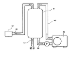
給湯器は、図3に示すように、一般的に、水を加熱するためのヒートポンプユニット40と、ヒートポンプユニット40において加熱された温水を貯留するための貯湯タンク41と、風呂の浴槽やシャワー、台所や洗面台の蛇口などの給水器42とから構成されている。
給湯器は、図3に示すように、一般的に、水を加熱するためのヒートポンプユニット40と、ヒートポンプユニット40において加熱された温水を貯留するための貯湯タンク41と、風呂の浴槽やシャワー、台所や洗面台の蛇口などの給水器42とから構成されている。
ヒートポンプユニット40は、圧縮機、ガスクーラ、膨張弁、および蒸発器を有する公知のものであり、ここでは、その詳細な説明は省略する。貯湯タンク41は、略円筒状のものであり、貯湯タンク41の下部には、給水配管43が接続されている。この給水配管43は、図示しない貯水タンクに接続されており、給水配管43を介して貯水タンクから水が供給される。また、貯湯タンク41の下部には、入水配管44が接続されている。この入水配管44は、ヒートポンプユニット40に接続されており、貯湯タンク41に供給された水は、入水配管44を介してヒートポンプユニット40に供給され、ヒートポンプユニット40により加熱されて所定温度の温水になる。温水は、出湯配管45を介して、貯湯タンク41に供給されて、貯湯タンク41内に貯留される。貯湯タンク41内に貯留された温水は、給湯配管46を介して給水器42に供給される。
本発明の給湯器は、図4に示すように、貯湯タンク41の表面を、上記構成の真空断熱材200を用いて覆うことに特徴を有している。これにより、給水器の貯湯タンク41のように、高温となるものについてもこれを効果的に断熱することができ、貯湯タンク41の熱が外部雰囲気へ放熱することを防止できる。なお、図4においては、貯湯タンク41の全面を真空断熱材200を用いて覆っているが、例えば、貯湯タンク41の周面だけのように貯湯タンク41の一部であっても構わない。
(2)カップ式自動販売機
カップ式自動販売機は、図示は省略するが、一般的には、加熱手段により加熱された飲料用の温水を貯留する貯湯タンクを内部に備えており、前記貯湯タンクから供給される温水を用いて、インスタントコーヒー粉末やインスタントココア粉末、インスタント紅茶粉末などの飲料原料から任意の温飲料を製造し、この温飲料をカップへ注いで販売するものである。
カップ式自動販売機は、図示は省略するが、一般的には、加熱手段により加熱された飲料用の温水を貯留する貯湯タンクを内部に備えており、前記貯湯タンクから供給される温水を用いて、インスタントコーヒー粉末やインスタントココア粉末、インスタント紅茶粉末などの飲料原料から任意の温飲料を製造し、この温飲料をカップへ注いで販売するものである。
本発明のカップ式自動販売機は、この種のカップ式自動販売機において、温水を貯留する前記貯湯タンクの表面を、上記構成の真空断熱材200を用いて覆うことに特徴を有している。これにより、カップ式自動販売機の貯湯タンクのように、高温となるものについてもこれを効果的に断熱することができ、前記貯湯タンクの熱が外部雰囲気へ放熱することを防止できる。
なお、本発明の真空断熱材は、上記した給湯器やカップ式自動販売機以外にも、加熱された高温の温水を貯留する貯湯タンクを内部に有する装置について、前記貯湯タンクの断熱材として、好適に用いることができる。
(3)商品収納装置
商品収納装置は、紙パック、缶、ビンまたはペットボトル入りの商品を販売する自動販売機や、店舗に設置される冷蔵および温蔵が可能なショーケースなど、商品を収納する収納庫内を仕切板により仕切って、商品を異なる温度(冷蔵状態または温蔵状態)で保存可能とするものである。
商品収納装置は、紙パック、缶、ビンまたはペットボトル入りの商品を販売する自動販売機や、店舗に設置される冷蔵および温蔵が可能なショーケースなど、商品を収納する収納庫内を仕切板により仕切って、商品を異なる温度(冷蔵状態または温蔵状態)で保存可能とするものである。
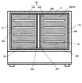
例えば、冷蔵および温蔵が可能なショーケースは、図5に示すように、内部に、商品を収納する収納庫50を備えている。収納庫50は、天枠板51、底枠板52、後枠板53および左右一対の側枠板54により構成されており、その内部は、複数の仕切板により複数の商品収納室に区画されている。図示例では、収納庫50は、1枚の仕切板55により、2つの商品収納室50A,50Bに区画されており、一方の商品収納室50Aが冷蔵室に、他方の商品収納室50Bが温蔵室になっている。冷蔵室50Aおよび温蔵室50Bは、図示しない冷却手段および加熱手段により、それぞれ冷却および加熱され、内部に収納された商品を、それぞれ冷蔵状態および温蔵状態で保存することが可能になっている。収納庫50を構成する各枠板51~54、および、収納庫50内に設けられた仕切板55は、断熱材により構成されているか、あるいは、各枠板51~54および仕切板55の表面などが断熱材により覆われているのが一般的である。
本発明の商品収納装置は、この種の商品を冷蔵状態および/または温蔵状態で保存可能な装置において、上記した収納庫50を構成する各枠板51~54の表面および収納庫50内に設けられた仕切板55の表面を、上記構成の真空断熱材200を用いて覆うこと、または、各枠板51~54および仕切板55を、上記構成の真空断熱材200により構成すること、に特徴を有している。これにより、温蔵室50Bのような高温となるものについてもこれを効果的に断熱することができ、冷蔵室50Aと温蔵室50Bとの間における冷気・暖気の流入・流出を防止できるとともに、外部雰囲気への冷気・暖気の流入・流出を防止することもできる。なお、図示例では、商品の収納庫50は、1枚の仕切板55により2つの商品収納室50A,50Bに区画されているが、これに限られるものではなく、2枚以上の仕切板を用いて、3つ以上の商品収納室に区画するように構成してもよい。
なお、図示例では、本発明の真空断熱材がショーケースの商品の収納庫に用いられている例を説明したが、自動販売機内に設けられた商品を異なる温度(冷蔵状態または温蔵状態)で保存可能な収納庫に対しても、本発明の真空断熱材を同様に用いることができるのは言うまでもない。
(4)車両用空気調和装置
車両用空気調和装置は、図6に示すように、一般的には、ダクト60内に、冷却器としてのエバポレータ61、加熱器としてのヒータコア62、ブロワ63、および空気反転空間64を備えている。ヒータコア62とエバポレータ61との間には、エアミックスダンパ65が設けられており、エバポレータ61を通過してきた空気の、ヒータコア62を通過する空気とヒータコア62をバイパスする空気の量を制御する。ヒータコア62よりも下流側の位置には、各種の吹出口66~68がそれぞれ開口している。ブロワ63によって送り出された空気は、エバポレータ61の一部領域からエバポレータ61内に流入し、エバポレータ61を通過した後、風向反転空間64に流入し、図6の矢印で示す風路に沿って、再びエバポレータ61の他部領域からエバポレータ61内に流入する。流入した空気は、エバポレータ61を通過し、エアミックスダンパ65の制御位置に応じて、ヒータコア62を通過するか、バイパスするか、両者のミックスモードとされるかのいずれかのモードで下流に送られ、温調された空気が、開度調節された各吹出口66~68に送られるようになっている。
車両用空気調和装置は、図6に示すように、一般的には、ダクト60内に、冷却器としてのエバポレータ61、加熱器としてのヒータコア62、ブロワ63、および空気反転空間64を備えている。ヒータコア62とエバポレータ61との間には、エアミックスダンパ65が設けられており、エバポレータ61を通過してきた空気の、ヒータコア62を通過する空気とヒータコア62をバイパスする空気の量を制御する。ヒータコア62よりも下流側の位置には、各種の吹出口66~68がそれぞれ開口している。ブロワ63によって送り出された空気は、エバポレータ61の一部領域からエバポレータ61内に流入し、エバポレータ61を通過した後、風向反転空間64に流入し、図6の矢印で示す風路に沿って、再びエバポレータ61の他部領域からエバポレータ61内に流入する。流入した空気は、エバポレータ61を通過し、エアミックスダンパ65の制御位置に応じて、ヒータコア62を通過するか、バイパスするか、両者のミックスモードとされるかのいずれかのモードで下流に送られ、温調された空気が、開度調節された各吹出口66~68に送られるようになっている。
本発明の車両用空気調和装置は、この種の車両用空気調和装置において、上記したダクト60の内面とヒータコア62(図示例では、ヒータコア62の上面および下面)との間に、上記構成の真空断熱材200を配設することに特徴を有している。これにより、ヒータコア62のような高温となるものについてもこれを効果的に断熱することができ、ヒータコア62の熱が外部雰囲気へ放熱することを防止できる。
なお、上記で説明した態様は、本発明の一態様を示したものであって、本発明は、これらの実施形態に限定されるものではなく、本発明の構成を備え、目的及び効果を達成できる範囲内での変形や改良が本発明の内容に含まれることは、いうまでもない。
以下、本発明を実施例によって、より詳細に説明するが、本発明はこれに限定されるものではない。
未延伸ポリプロピレンフィルムの揮発ガス含量は、次の段階を有する測定方法により測定した。
段階1:質量を測定したポリプロピレンフィルム0.2m2を、約0.004m2の小片に切断し、300ml三角フラスコに封入すること。
段階2:前記小片が封入された三角フラスコを、100℃で10分加熱して、フィルム内の揮発成分を揮発させること。
段階3:三角フラスコ内の気体2mlをガラス製マイクロシリンジにて採取すること。
段階4:採取した気体をガスクロマトグラフィー(島津製作所製、GC-14B又はその同等品)にてヘッドスペース法で分析すること。
段階1:質量を測定したポリプロピレンフィルム0.2m2を、約0.004m2の小片に切断し、300ml三角フラスコに封入すること。
段階2:前記小片が封入された三角フラスコを、100℃で10分加熱して、フィルム内の揮発成分を揮発させること。
段階3:三角フラスコ内の気体2mlをガラス製マイクロシリンジにて採取すること。
段階4:採取した気体をガスクロマトグラフィー(島津製作所製、GC-14B又はその同等品)にてヘッドスペース法で分析すること。
[比較例1]
(真空断熱パネル外袋用に用いる複合フィルムの製造)
まず、二軸延伸ポリエチレンテレフタレートフィルム(以下、PETと略称する場合がある)(ユニチカ社、ポリエステルフィルム エンブレットS)(厚さ12μm)に、ドライラミネート法で、二軸延伸ポリアミドフィルム(以下、ONYと略称する場合がある)(ユニチカ社、エンブレムNX)(厚さ15μm)を貼り合せた。
その後、ポリアミドフィルムの外面に、同じくドライラミネート法により、アルミ箔(日本製箔社、JIS8021)(厚さ6.5μm)を貼り合せ、更にアルミ箔の外面に、ドライラミネート法により、未延伸ポリプロピレンフィルム(以下、CPPと略称する場合がある)(東洋紡績社、パイレンフィルムP1146)(厚さ50μm)(揮発ガス含量0.026mg/g)を貼り合わせた。
これら4枚のフィルムの貼り合せにおける前記ドライラミネート法においては、ドライラミネート用接着剤として、タケラックA1143(三井化学社)とタケネートA-3(三井化学社)を5:1の比率で混合し、酢酸エチルで固形分23%まで希釈した後、グラビヤシリンダーで1つのフィルム表面に13g/m2の量で塗布した。
その後、乾燥炉を通過させて、固形分3.0g/m2の接着剤層を形成させ、この接着剤層表面に、ラミネートロールを用いて25℃~70℃程度の熱をかけながら、別のフィルムを貼り合せた。
(真空断熱パネル外袋用に用いる複合フィルムの製造)
まず、二軸延伸ポリエチレンテレフタレートフィルム(以下、PETと略称する場合がある)(ユニチカ社、ポリエステルフィルム エンブレットS)(厚さ12μm)に、ドライラミネート法で、二軸延伸ポリアミドフィルム(以下、ONYと略称する場合がある)(ユニチカ社、エンブレムNX)(厚さ15μm)を貼り合せた。
その後、ポリアミドフィルムの外面に、同じくドライラミネート法により、アルミ箔(日本製箔社、JIS8021)(厚さ6.5μm)を貼り合せ、更にアルミ箔の外面に、ドライラミネート法により、未延伸ポリプロピレンフィルム(以下、CPPと略称する場合がある)(東洋紡績社、パイレンフィルムP1146)(厚さ50μm)(揮発ガス含量0.026mg/g)を貼り合わせた。
これら4枚のフィルムの貼り合せにおける前記ドライラミネート法においては、ドライラミネート用接着剤として、タケラックA1143(三井化学社)とタケネートA-3(三井化学社)を5:1の比率で混合し、酢酸エチルで固形分23%まで希釈した後、グラビヤシリンダーで1つのフィルム表面に13g/m2の量で塗布した。
その後、乾燥炉を通過させて、固形分3.0g/m2の接着剤層を形成させ、この接着剤層表面に、ラミネートロールを用いて25℃~70℃程度の熱をかけながら、別のフィルムを貼り合せた。
(真空断熱パネルの製造)
前記のようにして製造した4辺形の複合フィルムの2枚を、CPP同士が対向するように重ねて配置し、トタニ技研工業社製 BH60形製袋機にて、4辺形の3方の端部に、各10mm巾のヒートシールバーにより約210℃の熱をかけることにより、前記CPP同士を熱融着させて280mm×350mmの3方袋に加工した。
この3方袋に、200mm×200mm×32mmの板状に形成した旭ファイバーグラス社製 グラスウール(繊維径4μm)を169℃で36分間乾燥させた後に封入し、真空チャンバー内(1.0×10⁻³Pa)にて3方袋の開口部を10mm巾のヒートシールバーにより165℃の熱をかけて熱融着させて、真空断熱パネルを製造した。
前記のようにして製造した4辺形の複合フィルムの2枚を、CPP同士が対向するように重ねて配置し、トタニ技研工業社製 BH60形製袋機にて、4辺形の3方の端部に、各10mm巾のヒートシールバーにより約210℃の熱をかけることにより、前記CPP同士を熱融着させて280mm×350mmの3方袋に加工した。
この3方袋に、200mm×200mm×32mmの板状に形成した旭ファイバーグラス社製 グラスウール(繊維径4μm)を169℃で36分間乾燥させた後に封入し、真空チャンバー内(1.0×10⁻³Pa)にて3方袋の開口部を10mm巾のヒートシールバーにより165℃の熱をかけて熱融着させて、真空断熱パネルを製造した。
[実施例1]
(真空断熱パネル外袋用に用いる複合フィルムの製造)
まず、二軸延伸ポリエチレンテレフタレートフィルム(以下、PETと略称する場合がある)(ユニチカ社、ポリエステルフィルム エンブレットS)(厚さ12μm)に、ドライラミネート法で、二軸延伸ポリアミドフィルム(以下、ONYと略称する場合がある)(ユニチカ社、エンブレムNX)(厚さ15μm)を貼り合せた。
その後、ポリアミドフィルムの外面に、同じくドライラミネート法により、アルミ箔(日本製箔社、JIS8021)(厚さ6.5μm)を貼り合せ、更にアルミ箔の外面に、ドライラミネート法により、未延伸ポリプロピレンフィルム(以下、CPPと略称する場合がある)(三井化学東セロ社、RXC11)(厚さ50μm)(揮発ガス量0.008mg/g)を貼り合わせた。
これら4枚のフィルムの貼り合せにおける前記ドライラミネート法においては、ドライラミネート用接着剤として、タケラックA1143(三井化学社)とタケネートA-3(三井化学社)を5:1の比率で混合し、酢酸エチルで固形分23%まで希釈した後、グラビヤシリンダーで1つのフィルム表面に13g/m2の量で塗布した。
その後、乾燥炉を通過させて、固形分3.0g/m2の接着剤層を形成させ、この接着剤層表面に、ラミネートロールを用いて25℃~70℃程度の熱をかけながら、別のフィルムを貼り合せた。
(真空断熱パネル外袋用に用いる複合フィルムの製造)
まず、二軸延伸ポリエチレンテレフタレートフィルム(以下、PETと略称する場合がある)(ユニチカ社、ポリエステルフィルム エンブレットS)(厚さ12μm)に、ドライラミネート法で、二軸延伸ポリアミドフィルム(以下、ONYと略称する場合がある)(ユニチカ社、エンブレムNX)(厚さ15μm)を貼り合せた。
その後、ポリアミドフィルムの外面に、同じくドライラミネート法により、アルミ箔(日本製箔社、JIS8021)(厚さ6.5μm)を貼り合せ、更にアルミ箔の外面に、ドライラミネート法により、未延伸ポリプロピレンフィルム(以下、CPPと略称する場合がある)(三井化学東セロ社、RXC11)(厚さ50μm)(揮発ガス量0.008mg/g)を貼り合わせた。
これら4枚のフィルムの貼り合せにおける前記ドライラミネート法においては、ドライラミネート用接着剤として、タケラックA1143(三井化学社)とタケネートA-3(三井化学社)を5:1の比率で混合し、酢酸エチルで固形分23%まで希釈した後、グラビヤシリンダーで1つのフィルム表面に13g/m2の量で塗布した。
その後、乾燥炉を通過させて、固形分3.0g/m2の接着剤層を形成させ、この接着剤層表面に、ラミネートロールを用いて25℃~70℃程度の熱をかけながら、別のフィルムを貼り合せた。
(真空断熱パネルの製造)
前記のようにして製造した4辺形の複合フィルムの2枚を、CPP同士が対向するように重ねて配置し、トタニ技研工業社製 BH60形製袋機にて、4辺形の3方の端部に、各10mm巾のヒートシールバーにより約210℃の熱をかけることにより、前記CPP同士を熱融着させて280mm×350mmの3方袋に加工した。
この3方袋に、200mm×200mm×32mmの板状に形成した旭ファイバーグラス社製 グラスウール(繊維径4μm)を169℃で36分間乾燥させた後に封入し、真空チャンバー内(1.0×10⁻³Pa)にて3方袋の開口部を10mm巾のヒートシールバーにより165℃の熱をかけて熱融着させて、真空断熱パネルを製造した。
前記のようにして製造した4辺形の複合フィルムの2枚を、CPP同士が対向するように重ねて配置し、トタニ技研工業社製 BH60形製袋機にて、4辺形の3方の端部に、各10mm巾のヒートシールバーにより約210℃の熱をかけることにより、前記CPP同士を熱融着させて280mm×350mmの3方袋に加工した。
この3方袋に、200mm×200mm×32mmの板状に形成した旭ファイバーグラス社製 グラスウール(繊維径4μm)を169℃で36分間乾燥させた後に封入し、真空チャンバー内(1.0×10⁻³Pa)にて3方袋の開口部を10mm巾のヒートシールバーにより165℃の熱をかけて熱融着させて、真空断熱パネルを製造した。
[実施例2]
実施例1で得られた複合フィルムを、45℃の大気下で168時間放置して実施例2の複合フィルムを得た。更に、当該複合フィルムを用いて、実施例2の真空断熱パネルを製造した。
実施例1で得られた複合フィルムを、45℃の大気下で168時間放置して実施例2の複合フィルムを得た。更に、当該複合フィルムを用いて、実施例2の真空断熱パネルを製造した。
[実施例3]
比較例1で得られた複合フィルムを、45℃の大気下で168時間放置して実施例3の複合フィルムを得た。更に、当該複合フィルムを用いて、実施例3の真空断熱パネルを製造した。
比較例1で得られた複合フィルムを、45℃の大気下で168時間放置して実施例3の複合フィルムを得た。更に、当該複合フィルムを用いて、実施例3の真空断熱パネルを製造した。
得られた各複合フィルムの揮発ガス量を、次の測定方法によって測定した。
(測定方法)
当該測定方法は、次の段階を有する。
段階1:ガスバリア性複合フィルム50mm×280mmを、約0.004m2の小片に切断し、300ml三角フラスコに封入すること。
段階2:前記小片が封入された三角フラスコを、80℃で30分加熱して、フィルム内の揮発成分を揮発させること。
段階3:三角フラスコ内の気体1mlをガラス製マイクロシリンジにて採取すること。
段階4:採取した気体を下記分析条件のガスクロマトグラフィーにてヘッドスペース法で分析すること。
(測定方法)
当該測定方法は、次の段階を有する。
段階1:ガスバリア性複合フィルム50mm×280mmを、約0.004m2の小片に切断し、300ml三角フラスコに封入すること。
段階2:前記小片が封入された三角フラスコを、80℃で30分加熱して、フィルム内の揮発成分を揮発させること。
段階3:三角フラスコ内の気体1mlをガラス製マイクロシリンジにて採取すること。
段階4:採取した気体を下記分析条件のガスクロマトグラフィーにてヘッドスペース法で分析すること。
実施例1~3の各複合フィルムの揮発ガス量を、表4に示す。
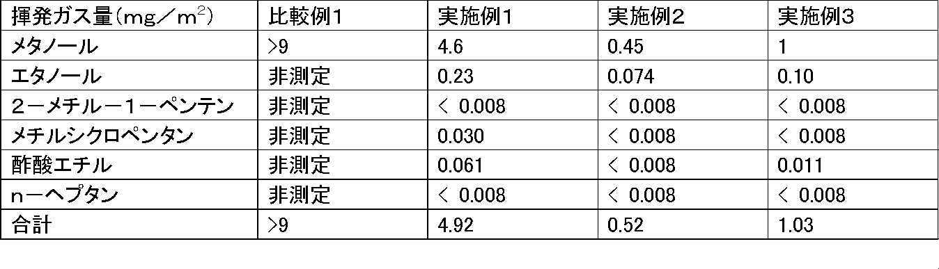
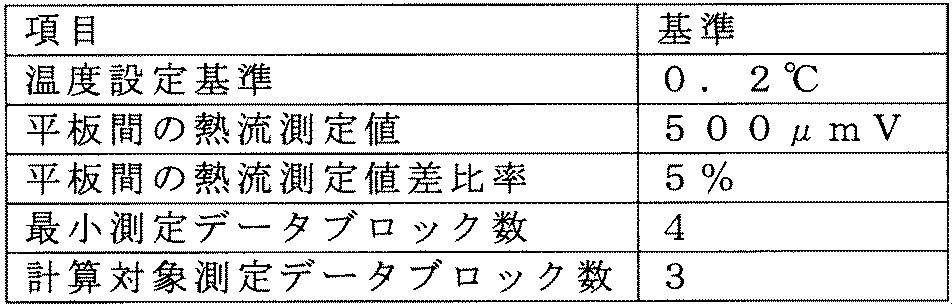
比較例1及び実施例1~3で作成した各真空断熱パネルの初期熱伝導率を、英弘精機社製 熱伝導率計計測システムオートAHC-074A(平板熱流計法、2枚熱流方式)で、表2(測定平行条件)、及び表3(測定温度条件)の測定条件にて熱伝導率の測定を行ったところ表4のようになった。
表3から、比較例1の真空断熱材は、高温条件下では断熱性能が低下したのに対し、実施例1~3の真空断熱材は高温条件下でも、断熱性能の低下が小さいことがわかる。


本発明のガスバリア性複合フィルムは、高温に曝される場所に使用された場合でも高い断熱性を示す真空断熱材の製造に用いることができる。
本発明の真空断熱材は、自然冷媒ヒートポンプ給湯機のタンク等の、高温に曝される場所の断熱に使用できる。
本発明の真空断熱材は、自然冷媒ヒートポンプ給湯機のタンク等の、高温に曝される場所の断熱に使用できる。
1 表面保護層
2 ガスバリア層
3 ポリプロピレンフィルム層
10 ガスバリア性複合フィルム
20 芯材
30 縁部
40 ヒートポンプユニット
41 貯湯タンク
42 給水器
43 給水配管
44 入水配管
45 出湯配管
46 給湯配管
50A 冷蔵室
50B 温蔵室
54 側枠板
55 仕切板
60 ダクト
61 エバポレータ
62 ヒータコア
63 ブロワ
64 風向反転空間
65 エアミックスダンパ
66 吹出口
100 外袋
200 真空断熱材
2 ガスバリア層
3 ポリプロピレンフィルム層
10 ガスバリア性複合フィルム
20 芯材
30 縁部
40 ヒートポンプユニット
41 貯湯タンク
42 給水器
43 給水配管
44 入水配管
45 出湯配管
46 給湯配管
50A 冷蔵室
50B 温蔵室
54 側枠板
55 仕切板
60 ダクト
61 エバポレータ
62 ヒータコア
63 ブロワ
64 風向反転空間
65 エアミックスダンパ
66 吹出口
100 外袋
200 真空断熱材
Claims (13)
- ガスバリア層、及びポリプロピレンフィルム層を含有し、
揮発ガス量が6mg/m2以下である
ガスバリア性複合フィルム。 - メタノール量とエタノール量の合計が5mg/m2以下である請求項1に記載のガスバリア性複合フィルム。
- 前記ポリプロピレンフィルム層が、気相法で製造されたポリプロピレン樹脂から構成されるポリプロピレンフィルム層である請求項1又は2に記載のガスバリア性複合フィルム。
- 前記ポリプロピレンフィルム層が、揮発ガス量が0.02mg/g以下であるポリプロピレンフィルムからなる請求項1~3のいずれか1項に記載のガスバリア性複合フィルム。
- ガスバリア層、及び熱融着層が、接着剤層によって互いに接着されている請求項1~4のいずれか1項に記載のガスバリア性複合フィルム。
- 前記接着剤層が、エポキシ変性ウレタン接着剤から形成されている請求項5に記載のガスバリア性複合フィルム。
- 真空断熱材の外袋材である請求項1~6のいずれか1項に記載のガスバリア性複合フィルム。
- 請求項1~7のいずれか1項に記載のガスバリア性複合フィルムからなる外袋と
前記外袋内に封入された芯材
とを備え、
前記外袋内部が減圧されている
真空断熱材。 - 給湯用の加熱された温水を貯留する貯湯タンクを備える給湯器において、
前記貯湯タンクの表面が請求項8に記載の真空断熱材により覆われていることを特徴とする給湯器。 - 飲料用の加熱された温水を貯留する貯湯タンクを備え、前記貯湯タンクから供給される温水と飲料の原料とにより得られる温飲料をカップへ注いで販売するカップ式自動販売機において、
前記貯湯タンクの表面が請求項8に記載の真空断熱材により覆われていることを特徴とするカップ式自動販売機。 - 商品を収納する収納庫を備え、前記収納庫内の商品を冷蔵状態および/または温蔵状態で保存する商品収納装置において、
前記収納庫の少なくとも前面を除く5面を構成する各枠板の内側面が請求項8に記載の真空断熱材により覆われている、または、前記各枠板が請求項8に記載の真空断熱材よりなることを特徴とする商品収納装置。 - 商品を収納する収納庫を備え、前記収納庫内の商品を冷蔵状態および/または温蔵状態で保存する商品収納装置において、
前記収納庫は、仕切板により区画された複数の商品収納室を有し、前記各商品収納室において商品を冷蔵状態または温蔵状態で保存可能であり、
前記仕切板の表面が請求項8に記載の真空断熱材により覆われている、または、前記仕切板が請求項8に記載の真空断熱材よりなることを特徴とする商品収納装置。 - ダクト内にヒータコアを収納した空調ユニットを備える車両用空気調和装置において、前記ダクトの内面と前記ヒータコアとの間に、請求項8に記載の真空断熱材が配設されていることを特徴とする車両用空気調和装置。
Priority Applications (1)
| Application Number | Priority Date | Filing Date | Title |
|---|---|---|---|
| JP2012537251A JP5335149B2 (ja) | 2011-05-25 | 2012-05-25 | ガスバリア性複合フィルム、及びこれを用いた真空断熱材 |
Applications Claiming Priority (2)
| Application Number | Priority Date | Filing Date | Title |
|---|---|---|---|
| JP2011-117316 | 2011-05-25 | ||
| JP2011117316 | 2011-05-25 |
Publications (1)
| Publication Number | Publication Date |
|---|---|
| WO2012161303A1 true WO2012161303A1 (ja) | 2012-11-29 |
Family
ID=47217368
Family Applications (1)
| Application Number | Title | Priority Date | Filing Date |
|---|---|---|---|
| PCT/JP2012/063431 Ceased WO2012161303A1 (ja) | 2011-05-25 | 2012-05-25 | ガスバリア性複合フィルム、及びこれを用いた真空断熱材 |
Country Status (2)
| Country | Link |
|---|---|
| JP (1) | JP5335149B2 (ja) |
| WO (1) | WO2012161303A1 (ja) |
Cited By (1)
| Publication number | Priority date | Publication date | Assignee | Title |
|---|---|---|---|---|
| JP2015155715A (ja) * | 2014-02-20 | 2015-08-27 | 凸版印刷株式会社 | 真空断熱材の外装材およびそれを用いた断熱容器 |
Families Citing this family (1)
| Publication number | Priority date | Publication date | Assignee | Title |
|---|---|---|---|---|
| JP5611440B2 (ja) * | 2012-11-28 | 2014-10-22 | 積水フィルム株式会社 | 真空断熱材 |
Citations (2)
| Publication number | Priority date | Publication date | Assignee | Title |
|---|---|---|---|---|
| JP2000218753A (ja) * | 1999-02-01 | 2000-08-08 | Mitsubishi Chemicals Corp | ガスバリア性積層フィルム |
| JP2001295986A (ja) * | 2000-04-11 | 2001-10-26 | Benkan Corp | 真空断熱材およびその製造方法 |
Family Cites Families (4)
| Publication number | Priority date | Publication date | Assignee | Title |
|---|---|---|---|---|
| JP2005114013A (ja) * | 2003-10-07 | 2005-04-28 | Matsushita Electric Ind Co Ltd | 真空断熱材 |
| JP5055847B2 (ja) * | 2006-06-09 | 2012-10-24 | 大日本印刷株式会社 | 真空断熱材用積層体及び真空断熱材 |
| JP2008045580A (ja) * | 2006-08-11 | 2008-02-28 | Hitachi Appliances Inc | 真空断熱パネル及びそれを備えた機器 |
| JP2009293708A (ja) * | 2008-06-05 | 2009-12-17 | Hitachi Appliances Inc | 真空断熱材およびそれを備えた機器並びに真空断熱材の製造方法 |
-
2012
- 2012-05-25 WO PCT/JP2012/063431 patent/WO2012161303A1/ja not_active Ceased
- 2012-05-25 JP JP2012537251A patent/JP5335149B2/ja not_active Expired - Fee Related
Patent Citations (2)
| Publication number | Priority date | Publication date | Assignee | Title |
|---|---|---|---|---|
| JP2000218753A (ja) * | 1999-02-01 | 2000-08-08 | Mitsubishi Chemicals Corp | ガスバリア性積層フィルム |
| JP2001295986A (ja) * | 2000-04-11 | 2001-10-26 | Benkan Corp | 真空断熱材およびその製造方法 |
Cited By (1)
| Publication number | Priority date | Publication date | Assignee | Title |
|---|---|---|---|---|
| JP2015155715A (ja) * | 2014-02-20 | 2015-08-27 | 凸版印刷株式会社 | 真空断熱材の外装材およびそれを用いた断熱容器 |
Also Published As
| Publication number | Publication date |
|---|---|
| JPWO2012161303A1 (ja) | 2014-07-31 |
| JP5335149B2 (ja) | 2013-11-06 |
Similar Documents
| Publication | Publication Date | Title |
|---|---|---|
| CN101046271B (zh) | 真空隔热材料、使用其的热水供给设备及电动式热水设备 | |
| EP3287278B1 (en) | Wrinkle free geometric opening in a vacuum insulated panel | |
| CN104870881B (zh) | 真空隔热件、具备其的隔热箱体以及真空隔热件的制造方法 | |
| US20030082357A1 (en) | Multi-layer core for vacuum insulation panel and insulated container including vacuum insulation panel | |
| CA2933154C (en) | Vacuum insulation panel and refrigerator including the same | |
| CN101427089B (zh) | 制冷系统及其温度分隔物 | |
| JP2017511445A5 (ja) | ||
| CN102996978B (zh) | 真空绝热材料及使用真空绝热材料的电冰箱及供热水器 | |
| JP2017511445A (ja) | 真空断熱材およびこれを含む冷蔵庫 | |
| JP5611440B2 (ja) | 真空断熱材 | |
| WO2017098694A1 (ja) | 真空断熱体、それを備える断熱機器、及び真空断熱体の製造方法 | |
| JP2007211884A (ja) | 真空断熱箱体 | |
| JP5335149B2 (ja) | ガスバリア性複合フィルム、及びこれを用いた真空断熱材 | |
| CN107110588B (zh) | 吸附剂、具有其的真空绝热材料和制冷机 | |
| JP5571610B2 (ja) | 真空断熱材の製造方法、真空断熱材及びこれを備えた冷蔵庫 | |
| CN108496037B (zh) | 保温体、真空隔热材料及真空隔热材料的制造方法 | |
| CN106052238B (zh) | 真空隔离面板以及包括该真空隔离面板的电冰箱 | |
| KR20140100411A (ko) | 진공 단열재, 단열 케이스체 및 냉장고 | |
| US20090114378A1 (en) | Heat exchanger and tempering container comprising a heat exchanger | |
| CN206449358U (zh) | 真空隔热体和使用其的隔热容器、隔热壁 | |
| JP2015105806A (ja) | 真空断熱箱体 | |
| JPH08152258A (ja) | 真空断熱材 | |
| JP6225324B2 (ja) | 断熱箱体 | |
| CN108437572A (zh) | 一种冰箱用调湿装置和调湿片及其制备方法 | |
| JP2013087806A (ja) | 断熱壁および断熱箱体 |
Legal Events
| Date | Code | Title | Description |
|---|---|---|---|
| ENP | Entry into the national phase |
Ref document number: 2012537251 Country of ref document: JP Kind code of ref document: A |
|
| 121 | Ep: the epo has been informed by wipo that ep was designated in this application |
Ref document number: 12789539 Country of ref document: EP Kind code of ref document: A1 |
|
| NENP | Non-entry into the national phase |
Ref country code: DE |
|
| 122 | Ep: pct application non-entry in european phase |
Ref document number: 12789539 Country of ref document: EP Kind code of ref document: A1 |