WO2012161079A1 - 受信装置、送信装置及び無線通信方法 - Google Patents
受信装置、送信装置及び無線通信方法 Download PDFInfo
- Publication number
- WO2012161079A1 WO2012161079A1 PCT/JP2012/062645 JP2012062645W WO2012161079A1 WO 2012161079 A1 WO2012161079 A1 WO 2012161079A1 JP 2012062645 W JP2012062645 W JP 2012062645W WO 2012161079 A1 WO2012161079 A1 WO 2012161079A1
- Authority
- WO
- WIPO (PCT)
- Prior art keywords
- orthogonal
- signal
- signals
- addressed
- receiving device
- Prior art date
- Legal status (The legal status is an assumption and is not a legal conclusion. Google has not performed a legal analysis and makes no representation as to the accuracy of the status listed.)
- Ceased
Links
Images




Classifications
-
- H—ELECTRICITY
- H04—ELECTRIC COMMUNICATION TECHNIQUE
- H04B—TRANSMISSION
- H04B1/00—Details of transmission systems, not covered by a single one of groups H04B3/00 - H04B13/00; Details of transmission systems not characterised by the medium used for transmission
- H04B1/06—Receivers
- H04B1/10—Means associated with receiver for limiting or suppressing noise or interference
-
- H—ELECTRICITY
- H04—ELECTRIC COMMUNICATION TECHNIQUE
- H04J—MULTIPLEX COMMUNICATION
- H04J11/00—Orthogonal multiplex systems, e.g. using WALSH codes
- H04J11/0023—Interference mitigation or co-ordination
- H04J11/0026—Interference mitigation or co-ordination of multi-user interference
- H04J11/0036—Interference mitigation or co-ordination of multi-user interference at the receiver
-
- H—ELECTRICITY
- H04—ELECTRIC COMMUNICATION TECHNIQUE
- H04J—MULTIPLEX COMMUNICATION
- H04J13/00—Code division multiplex systems
- H04J13/0007—Code type
- H04J13/004—Orthogonal
-
- H—ELECTRICITY
- H04—ELECTRIC COMMUNICATION TECHNIQUE
- H04L—TRANSMISSION OF DIGITAL INFORMATION, e.g. TELEGRAPHIC COMMUNICATION
- H04L5/00—Arrangements affording multiple use of the transmission path
- H04L5/003—Arrangements for allocating sub-channels of the transmission path
- H04L5/0037—Inter-user or inter-terminal allocation
-
- H—ELECTRICITY
- H04—ELECTRIC COMMUNICATION TECHNIQUE
- H04W—WIRELESS COMMUNICATION NETWORKS
- H04W72/00—Local resource management
- H04W72/12—Wireless traffic scheduling
Definitions
- the present invention relates to a receiving apparatus, a transmitting apparatus, and a wireless communication method adapted to non-orthogonal multi-access.
- LTE Long Term Evolution
- 3GPP 3rd Generation Partnership Project
- orthogonal multi-access using orthogonal signals in which a plurality of signals do not interfere with each other is performed between a base station and a user terminal (mobile station).
- LTE Long Term Evolution
- mobile station a user terminal
- non-orthogonal multiple access using non-orthogonal signals has been proposed in order to increase the capacity of a mobile communication system (see, for example, Non-Patent Document 1).
- signal separation In non-orthogonal multi-access, signal separation (interference canceller) based on nonlinear signal processing is assumed.
- the base station transmits non-orthogonal signals simultaneously to a plurality of user terminals.
- Each user terminal demodulates the received non-orthogonal signal after removing a signal to a user terminal (at the cell edge) having a path loss larger than that of the user terminal by signal processing.
- each user terminal that is, a mobile station
- each user terminal needs to demodulate after removing a signal to a mobile station having a path loss larger than that of its own device by signal processing. For this reason, the processing load on the mobile station is high, and the problem of an increase in cost and processing delay of the mobile station may occur.
- an object of the present invention is to provide a receiving device, a transmitting device, and a wireless communication method that can use non-orthogonal multi-access while suppressing cost increase and processing delay.
- a first feature of the present invention is that a radio signal receiving unit (physical channel demultiplexing unit 210) that receives a radio signal including a plurality of orthogonal signals orthogonal to each other and a plurality of non-orthogonal signals not orthogonal to each other; By using a quadrature signal included in a radio signal received by the radio signal receiver, a radio signal destined for another receiving device is demodulated and canceled from among a plurality of non-orthogonal signals.
- a radio signal receiving unit physical channel demultiplexing unit 210) that receives a radio signal including a plurality of orthogonal signals orthogonal to each other and a plurality of non-orthogonal signals not orthogonal to each other;
- An interference cancellation unit (data demodulation / decoding unit 220) that extracts a signal, a signal destined for the receiving device included in the orthogonal signal, and a non-orthogonal signal destined for the receiving device extracted by the interference cancellation unit
- the gist of the present invention is a receiving device (for example, mobile station 200A) including a demodulating unit (data demodulating / decoding unit 220).
- a second feature of the present invention is that a radio including a plurality of non-orthogonal signals that are not orthogonal to each other and transmitted using a part or all of the orthogonal resources among orthogonal resources that are a plurality of radio resources orthogonal to each other.
- a radio signal receiving unit that receives signals, and a radio signal received by the radio signal receiving unit extracts an orthogonal resource including a non-orthogonal signal addressed to the receiving device, and a plurality of the orthogonal resources included in the extracted orthogonal resource
- An interference cancellation unit that extracts a non-orthogonal signal addressed to the receiving device by demodulating and canceling a radio signal addressed to another receiving device, and the reception extracted by the interference canceling unit
- the gist of the present invention is a receiving device including a demodulator that demodulates a non-orthogonal signal addressed to the device.
- a radio signal including a plurality of orthogonal signals orthogonal to each other and a plurality of non-orthogonal signals in which the plurality of signals are not orthogonal to each other is directed to a plurality of receiving apparatuses located in the cell.
- Wireless path transmitters hybrid orthogonal / non-orthogonal multiplexing unit 130 and physical channel multiplexing unit 160 for transmitting the signals and the path loss of the signals multiplexed as the non-orthogonal signals to each of the receiving devices.
- the gist of the present invention is a transmission apparatus (base station 100) including a scheduling unit (base station scheduler 120) for scheduling a signal multiplexed as the non-orthogonal signal so that the difference becomes large.
- the communication device receives a radio signal including a plurality of orthogonal signals orthogonal to each other and a plurality of non-orthogonal signals in which the plurality of signals are not orthogonal to each other, and the communication
- the apparatus demodulates and cancels a radio signal addressed to another receiving apparatus from among a plurality of non-orthogonal signals, using the orthogonal signal included in the radio signal received by the radio signal receiving unit. Extracting a non-orthogonal signal addressed to the communication device, and demodulating the signal addressed to the receiving device included in the orthogonal signal and the non-orthogonal signal addressed to the receiving device extracted in the extracting step.
- a wireless communication method including a step of demodulating a signal destined for the own apparatus extracted by the interference cancellation unit and a signal destined for the own apparatus included in the orthogonal signal. The gist of the door.
- a fifth feature of the present invention is that a communication device includes a plurality of non-orthogonal signals that are not orthogonal to each other and transmitted using a part or all of the orthogonal resources among orthogonal resources that are a plurality of radio resources orthogonal to each other.
- a step of extracting a non-orthogonal signal addressed to the receiving device by demodulating and canceling a radio signal addressed to another receiving device from the non-orthogonal signals, and the communication device addressed to the extracted receiving device And a step of demodulating the non-orthogonal signal.
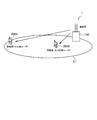
- FIG. 1 is an overall schematic configuration diagram of a mobile communication system 1 according to an embodiment of the present invention.
- FIG. 2 is a diagram illustrating radio resource allocation images for orthogonal multi-access, non-orthogonal multi-access, and hybrid orthogonal / non-orthogonal multi-access.
- FIG. 3 is a diagram illustrating a specific radio resource allocation image of hybrid orthogonal / non-orthogonal multi-access.
- FIG. 4 is a functional block configuration diagram of a transmission unit of the base station 100 according to the embodiment of the present invention.
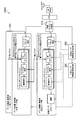
- FIG. 5 is a functional block configuration diagram of the receiving unit of the mobile station 200A according to the embodiment of the present invention.
- FIG. 6 is a diagram showing an example of scheduling of mobile stations to non-orthogonal signals in the base station 100 according to the embodiment of the present invention.
- FIG. 7 is a diagram showing an example (RBG unit) of an allocation map of orthogonal multi-access and non-orthogonal multi-access according to another embodiment of the present invention.
- FIG. 8 is a diagram illustrating an example (REG unit) of an allocation map of orthogonal multi-access and non-orthogonal multi-access according to another embodiment of the present invention.
- FIG. 1 is an overall schematic configuration diagram of a mobile communication system 1 according to the present embodiment. As shown in FIG. 1, the mobile communication system 1 includes a base station 100 and mobile stations 200A and 200B.
- the base station 100 transmits a radio signal toward the mobile stations 200A and 200B, specifically, into the cell C1.
- the base station 100 receives radio signals from the mobile stations 200A and 200B.
- the base station 100 constitutes a transmitting device
- the mobile stations 200A and 200B constitute a receiving device.
- the mobile station 200A is located in the cell end of the cell C1, which is located in the cell C1, but has a large path loss of the radio signal from the base station 100.
- Mobile station 200B is located in the center of cell C1. For this reason, the path loss of the radio signal from the base station 100 is smaller than the path loss in the mobile station 200A.
- the base station 100 and the mobile stations 200A and 200B are mobile stations 200A located in the cell C1 with radio signals including a plurality of orthogonal signals orthogonal to each other and a plurality of non-orthogonal signals not orthogonal to each other. , Send to 200B. That is, in the mobile communication system 1, the orthogonal multi-access that realizes simultaneous communication with a plurality of mobile stations using orthogonal signals and the non-orthogonal multi-access that realizes simultaneous communication with a plurality of mobile stations using non-orthogonal signals. Access is used together (hereinafter referred to as hybrid orthogonal / non-orthogonal multiple access).
- FIGS. 2A to 2C show radio resource allocation images of orthogonal multi-access, non-orthogonal multi-access, and hybrid orthogonal / non-orthogonal multi-access.
- radio resources allocated to each mobile station (user) do not overlap in the frequency domain / time domain / space domain. For this reason, in the orthogonal multi-access, in principle, it is not necessary to remove interference caused by radio resources allocated to other mobile stations.
- Orthogonal multiple access is also used in LongLTerm Evolution (LTE), which is standardized in 3GPP.
- LTE LongLTerm Evolution
- Non-Patent Document 1 As shown in FIG. 2B, in non-orthogonal multi-access, radio resources allocated to each mobile station overlap in the band. For this reason, the mobile station needs to remove all multi-access interference by signal processing. For specific signal processing, the technique described in Non-Patent Document 1 described above can be used.
- the radio resources allocated to each mobile station partially overlap in the band. For this reason, the mobile station only needs to remove multi-access interference equal to or less than the specified number in accordance with the number of multiplexed radio resources.
- 3 (a) and 3 (b) show more specific assignment images of hybrid orthogonal / non-orthogonal multi-access.
- orthogonal signals and non-orthogonal signals are transmitted to each user (user 1 to user 3).
- the mobile station can extract a non-orthogonal signal using the orthogonal signal.
- the signal processing load associated with the removal of multi-access interference is reduced, and the number of multi-access interference to be removed by the mobile station is recognized.
- a wireless interface that can be used is defined.
- the assignment image illustrated in FIG. 3A will be mainly described as an example.
- FIG. 4 is a functional block configuration diagram of the transmission unit of the base station 100.
- FIG. 5 is a functional block configuration diagram of the receiving unit of the mobile station 200A.
- the transmission unit of the base station 100 includes an encoding / data modulation unit 110, a base station scheduler 120, a hybrid orthogonal / non-orthogonal multiplexing unit 130, a control signal generation unit 140, a control signal resource allocation unit 150, A physical channel multiplexing unit 160 is provided.
- the encoding / data modulation unit 110 performs transmission data division, channel coding / data modulation, transmission power setting, and resource block allocation for each predetermined user (user k).
- the base station scheduler 120 is based on feedback of Circuit State Information (CSI) from the mobile stations 200A and 200B and a path loss between the base station 100 and the mobile stations 200A and 200B. Control the non-orthogonal multiplexing unit 130 and the control signal generation unit 140.
- CSI Circuit State Information
- the base station scheduler 120 increases the difference in path loss based on the path loss to each of a plurality of mobile stations (for example, mobile stations 200A and 200B) of signals multiplexed as non-orthogonal signals.
- a signal multiplexed as a non-orthogonal signal is scheduled to the plurality of mobile stations.
- FIG. 6 shows an example of scheduling of a mobile station to a non-orthogonal signal in the base station 100.
- a non-orthogonal signal in which a maximum of four users (mobile stations) are multiplexed is used.
- a plurality of signals are not orthogonal, that is, the same radio resource block is allocated in the frequency domain or the time domain.
- a signal addressed to a mobile station with a small path loss is sequentially multiplexed as a non-orthogonal signal from a signal addressed to a mobile station with a small path loss.
- a signal addressed to a mobile station with a small path loss may have a small ratio in the vertical axis (transmission power) direction in FIG. 6 because transmission power for securing a desired SNR may be small.
- a signal addressed to a mobile station with a large path loss has a large transmission power for securing a desired SNR, and therefore, the ratio of the signal in the vertical axis (transmission power) direction in FIG. 6 is large.
- a user (mobile station) having the second smallest path loss needs to remove interference from signals assigned to two mobile stations having a larger path loss than the user. Yes (see explanation in the figure).
- different radio resource blocks are allocated in the frequency domain and the time domain, that is, orthogonal signals in which a plurality of signals are orthogonal to each other are also used. Since no interference occurs, the mobile station does not need to cancel the interference.
- the hybrid orthogonal / non-orthogonal multiplexing unit 130 multiplexes orthogonal signals and non-orthogonal signals. Specifically, the hybrid orthogonal / non-orthogonal multiplexing unit 130 multiplexes signals (radio resource blocks) output from the plurality of encoding / data modulation units 110 based on control from the base station scheduler 120. As a result, a multiplexed signal is generated as shown in FIG.
- the control signal generator 140 generates various control signals to be notified to the mobile stations 200A and 200B.
- the maximum number of signals multiplexed as non-orthogonal signals is known (for example, 4 multiplexing) in the base station 100 and the mobile stations 200A and 200B.
- the control signal generator 140 generates a control signal necessary for the mobile station to demodulate and cancel a radio signal addressed to another mobile station (another device).
- the control signal generation unit 140 can generate a signal including control information or a reference signal as described below in order for the mobile station to demodulate and cancel a radio signal addressed to another mobile station (another device), for example.
- control signal generation unit 140 may generate a control signal that is a combination of any one of (a) to (d) described above or a plurality thereof.
- the control signal generation unit 140 transmits the generated control signal to the mobile stations 200A and 200B via the control signal resource allocation unit 150 and the physical channel multiplexing unit 160.
- the control signal generation unit 140 constitutes a control signal transmission unit.
- the control signal resource allocation unit 150 allocates a radio resource block to the control signal output from the control signal generation unit 140.
- the physical channel multiplexing unit 160 multiplexes the baseband signal output from the hybrid orthogonal / non-orthogonal multiplexing unit 130 and the control signal output from the control signal resource allocation unit 150 on the physical channel.
- the signal output from the physical channel multiplexing unit 160 is subjected to IFFT, added with a Cyclic Prefix (CP), and transmitted from the transmitting antenna to the mobile stations 200A and 200B.
- CP Cyclic Prefix
- a transmission unit is configured.
- hybrid orthogonal / non-orthogonal multiplexing unit 130 and the physical channel multiplexing unit 160 allow each mobile station (receiving device) to extract orthogonal resources including non-orthogonal signals addressed to the mobile station. Necessary information can also be transmitted to the mobile station using orthogonal signals.
- signals transmitted as orthogonal signals include control signals, reference signals, and data signals with a small payload size (Voice over IP (VoIP), TCP ACK, etc.).
- the mobile station demodulates the non-orthogonal signal using the orthogonal signal, but demodulates the orthogonal signal as it is. Note that the boundary between the orthogonal signal (orthogonal resource) and the non-orthogonal signal (non-orthogonal resource) may be fixed, or may be notified as variable system information to each user.
- the mobile station 200A includes a physical channel separation unit 210, a data demodulation / decoding unit 220, a target user control signal detection unit 230, and an interference user control signal detection unit 240. Note that the mobile station 200B also has the same functional block configuration as the mobile station 200A.
- the physical channel separation unit 210 receives a radio signal transmitted from the base station 100 and separates a physical channel included in the radio signal. As described above, the radio signal received by the physical channel separation unit 210 includes an orthogonal signal and a non-orthogonal signal. The separated physical channel is output to the data demodulation / decoding unit 220, the target user control signal detection unit 230, and the interference user control signal detection unit 240. In the present embodiment, the physical channel separation unit 210 constitutes a radio signal reception unit.
- a plurality of data demodulation / decoding units 220 are provided. Specifically, the data demodulating / decoding unit 220 is provided for the interference user and the target user according to the number of signals (users) multiplexed as non-orthogonal signals. In this embodiment, since up to four users are multiplexed, it is preferable that four data demodulation / decoding units 220 are also provided.
- the data demodulation / decoding unit 220 executes radio resource block extraction, interference canceller, channel estimation, demodulation decoding, and decoding data decoding.
- the interference canceller of the data demodulation / decoding unit 220 uses a quadrature signal (for example, the control information and the reference signal described above) included in the received radio signal, from among a plurality of non-orthogonal signals.
- a non-orthogonal signal addressed to the mobile station 200A is extracted by demodulating and canceling a radio signal addressed to another mobile station (receiving device).
- the interference canceller extracts a signal addressed to itself from the received non-orthogonal signal by signal separation by predetermined signal processing, and cancels interference due to a signal addressed to another receiving device.
- the interference canceller has a known maximum number of non-orthogonal signals to be multiplexed (in this embodiment, four multiplexing), and therefore the radio addressed to other receiving apparatuses is within a range not exceeding the known maximum number of non-orthogonal signals. Demodulate and cancel the signal. A method for canceling interference will be described later.
- the target user control signal detection unit 230 detects a control signal addressed to the target user, that is, the own apparatus (mobile station 200A).
- the target user control signal detection unit 230 provides the detected control signal to the data demodulation / decoding unit 220 (for the target user).
- the control signal any one or combination of (a) to (d) as described above is used.
- Interference user control signal detector 240 detects a control signal addressed to an interference user, that is, another device (for example, mobile station 200B). Similar to the target user control signal detection unit 230, the interference user control signal detection unit 240 provides the detected control signal to the data demodulation / decoding unit 220 (for interference users).
- the interference canceller of the data demodulation / decoding unit 220 will be briefly described.
- the interference canceller cannot remove the signal of the mobile station 200B located in the center of the cell C1, so that data demodulation / decoding is performed.
- the unit 220 performs demodulation / decoding as it is.
- the signal processing in the user 1 can be described based on the following calculation formula.
- the user 1 shows a mobile station 200A located at the cell edge of the cell C1
- the user 2 shows a mobile station 200B located at the center in the cell C1.
- P 1 and P 2 are transmission powers of user 1 and user 2.
- h 1 and h 2 are channel gains of user 1 and user 2.
- the received signal (R 1 ) includes interference with the mobile station (user 2) located in the center of the cell. And since SNR is bad, the interference from the user 2 cannot be removed. Therefore, the user 1 performs demodulation / decoding as it is without removing the signal of the user 2.
- the signal processing in the user 2 can be described based on the following calculation formula.
- the received signal (R 2 ) includes interference with the mobile station (user 1) located at the cell edge. Since the SNR is good, the signal of the user 1 is once removed by decoding, and after the signal is removed, the signal of the user 2 is demodulated / decoded.
- the maximum number of signals multiplexed as non-orthogonal signals is known in the base station 100 and the mobile stations 200A and 200B.
- the interference canceller of the data demodulating / decoding unit 220 demodulates and cancels interference caused by signals addressed to other devices in a range not exceeding the known maximum number of the signals. Therefore, the mobile stations 200A and 200B can be designed so that the delay time required for demodulation / decoding is within a certain range.
- a signal multiplexed as a non-orthogonal signal so that a difference in the path loss becomes large based on a path loss of each of the signals multiplexed as a non-orthogonal signal to the plurality of mobile stations. Scheduled. For this reason, variations in SNR between signals multiplexed as non-orthogonal signals are likely to increase, and it becomes easy to remove interference caused by signals addressed to other devices.
- the physical channel separation unit 210 (radio signal reception unit) of the mobile station 200A is one of the orthogonal resources among the orthogonal resources that are a plurality of radio resources orthogonal to each other.
- a wireless signal including a plurality of non-orthogonal signals transmitted using a part or all of them is received.
- the interference canceller of the data demodulation / decoding unit 220 extracts an orthogonal resource including a non-orthogonal signal addressed to the mobile station 200A from the received radio signal. Further, the interference canceller demodulates and cancels a radio signal addressed to another mobile station (mobile station 200B) from among a plurality of non-orthogonal signals included in the extracted orthogonal resource, thereby non-orthogonal addressed to the mobile station 200A. Extract the signal. Further, the data demodulation / decoding unit 220 demodulates the non-orthogonal signal destined for the mobile station 200A extracted by the interference canceller.
- the base station 100 may transmit an allocation map indicating radio resources used for orthogonal multi-access and radio resources used for non-orthogonal multi-access to the mobile stations 200A and 200B.
- FIG. 7 and 8 show examples of allocation maps for orthogonal multi-access and non-orthogonal multi-access. Specifically, FIG. 7 shows an example of an allocation map in units of radio resource blocks (Resource block), and FIG. 8 shows an example of an allocation map in units of radio resource elements (Resource element).
- Resource block shows an example of an allocation map in units of radio resource blocks
- Resource element shows an example of an allocation map in units of radio resource elements
- Base station 100 determines the ratio of Resource block or Resource element that transmits data by orthogonal multi-access or non-orthogonal multi-access, according to the degree of difference in SNR.
- the base station 100 determines whether the allocation part (corresponding Resource block (RB) or Resource element (RE)) by orthogonal multi-access and the non-orthogonal multi-access part (corresponding RB or RE) according to the difference in SNR.
- the allocation map (see FIGS. 7 and 8) is transmitted to the mobile stations 200A and 200B.
- the base station 100 determines the degree of SNR difference based on the CSI information fed back from each mobile station.
- Base station 100 processes non-orthogonal multiaccess for RB and RE having a relatively large difference in SNR, and processes RB and RE having a relatively small difference in SNR as orthogonal multiaccess.
- the base station 100 transmits an allocation map based on such a processing result to the mobile stations 200A and 200B. It should be noted that DL ⁇ ⁇ ⁇ ⁇ grant, RRC signaling or the like may be used as means for notifying the contents of the allocation map.
- the example in the downlink direction from the base station 100 to the mobile stations 200A and 200B has been described, but the hybrid orthogonal / non-orthogonal multiple access according to the present invention is applied to the uplink direction. Also good.
- the present invention is not limited to between a base station and a mobile station, and may be applied to wireless communication between base stations.
- the characteristics of the present invention it is possible to provide a receiving device, a transmitting device, and a wireless communication method that can use non-orthogonal multi-access while suppressing cost increase and processing delay.
- DESCRIPTION OF SYMBOLS 1 ... Mobile communication system 100 ... Base station 110 ... Coding / data modulation part 120 ... Base station scheduler 130 ... Hybrid orthogonal / non-orthogonal multiplexing part 140 ... Control signal generation part 150 ... Control signal resource allocation part 160 ... Physical channel multiplexing 200A, 200B ... mobile station 210 ... physical channel separation unit 220 ... data demodulation / decoding unit 230 ... target user control signal detection unit 240 ... interference user control signal detection unit
Landscapes
- Engineering & Computer Science (AREA)
- Signal Processing (AREA)
- Computer Networks & Wireless Communication (AREA)
- Mobile Radio Communication Systems (AREA)
Abstract
コスト上昇や処理遅延を抑制しつつ、非直交マルチアクセスを利用し得る受信装置、送信装置及び無線通信方法を提供する。移動局200Aは、互いに直交する複数の直交信号と、互いに直交しない複数の非直交信号とが含まれた無線信号を受信する物理チャネル分離部210と、物理チャネル分離部210が受信した無線信号に含まれる直交信号を用いて、複数の非直交信号の中から、他の移動局宛ての無線信号を復調及びキャンセルすることによって、移動局200A宛ての非直交信号を抽出するとともに、直交信号に含まれる移動局200A宛ての信号と、抽出した移動局200A宛ての非直交信号とを復調するデータ復調/復号部220とを備える。
Description
本発明は、非直交マルチアクセスに適応する受信装置、送信装置及び無線通信方法に関する。
移動体通信システム、例えば、3GPPにおいて標準化されたLong Term Evolution(LTE)では、基地局とユーザ端末(移動局)との間において、複数の信号が互いに干渉しない直交信号を用いた直交マルチアクセスが広く用いられている。一方、移動体通信システムのキャパシティを増大させるため、非直交信号を用いた非直交マルチアクセスが提案されている(例えば、非特許文献1参照)。
非直交マルチアクセスでは、非線形信号処理による信号分離(干渉キャンセラ)が前提となっている。例えば、下りリンクの場合、基地局が複数のユーザ端末宛てに非直交信号を同時送信する。各ユーザ端末は、受信した非直交信号の中から、自端末よりもパスロスの大きい(セル端の)ユーザ端末への信号を信号処理により除去してから復調する。
D. Tse and P. Viswanath, "Fundamentals of Wireless Communication", Cambridge University Press、2005年、インターネット<http://www.eecs.berkeley.edu/~dtse/book.html>
上述したように、非直交マルチアクセスの場合、各ユーザ端末、つまり、移動局は、自装置よりもパスロスの大きい移動局への信号を信号処理により除去してから復調する必要がある。このため、移動局における処理負荷が高く、移動局のコスト上昇や処理遅延の問題が生じ得る。
そこで、本発明は、このような状況を鑑みてなされたものであり、コスト上昇や処理遅延を抑制しつつ、非直交マルチアクセスを利用し得る受信装置、送信装置及び無線通信方法の提供を目的とする。
本発明の第1の特徴は、互いに直交する複数の直交信号と、互いに直交しない複数の非直交信号とが含まれた無線信号を受信する無線信号受信部(物理チャネル分離部210)と、前記無線信号受信部が受信した無線信号に含まれる直交信号を用いて、複数の非直交信号の中から、他の受信装置宛ての無線信号を復調及びキャンセルすることによって、当該受信装置宛ての非直交信号を抽出する干渉キャンセル部(データ復調/復号部220)と、前記直交信号に含まれる当該受信装置宛ての信号と、前記干渉キャンセル部によって抽出された当該受信装置宛ての非直交信号とを復調する復調部(データ復調/復号部220)とを備える受信装置(例えば、移動局200A)であることを要旨とする。
本発明の第2の特徴は、互いに直交する複数の無線リソースである直交リソースのうち、前記直交リソースの一部または全てを用いて送信された互いに直交しない複数の非直交信号が含まれた無線信号を受信する無線信号受信部と、前記無線信号受信部が受信した無線信号の中から、前記受信装置宛ての非直交信号が含まれる直交リソースを抽出し、抽出した前記直交リソースに含まれる複数の非直交信号の中から、他の受信装置宛ての無線信号を復調及びキャンセルすることによって、当該受信装置宛ての非直交信号を抽出する干渉キャンセル部と、前記干渉キャンセル部によって抽出された当該受信装置宛ての非直交信号を復調する復調部とを備える受信装置であることを要旨とする。
本発明の第3の特徴は、互いに直交する複数の直交信号と、互いに前記複数の信号が直交しない複数の非直交信号とが含まれた無線信号をセル内に位置する複数の受信装置に向けて送信する無線信号送信部(ハイブリッド直交/非直交多重部130及び物理チャネル多重部160)と、前記非直交信号として多重される信号の前記受信装置のそれぞれまでのパスロスに基づいて、前記パスロスの差が大きくなるように前記非直交信号として多重される信号をスケジューリングするスケジューリング部(基地局スケジューラ120)とを備える送信装置(基地局100)であることを要旨とする。
本発明の第4の特徴は、通信装置が、互いに直交する複数の直交信号と、互いに前記複数の信号が直交しない複数の非直交信号とが含まれた無線信号を受信するステップと、前記通信装置が、前記無線信号受信部が受信した無線信号に含まれる直交信号を用いて、複数の非直交信号の中から、他の受信装置宛ての無線信号を復調及びキャンセルすることによって、当該受信装置宛ての非直交信号を抽出するステップと、前記通信装置が、前記直交信号に含まれる当該受信装置宛ての信号と、前記抽出するステップにおいて抽出された当該受信装置宛ての非直交信号とを復調する前記干渉キャンセル部によって抽出された前記自装置宛ての信号と、前記直交信号に含まれる自装置宛ての信号とを復調するステップとを含む無線通信方法であることを要旨とする。
本発明の第5の特徴は、通信装置が、互いに直交する複数の無線リソースである直交リソースのうち、前記直交リソースの一部または全てを用いて送信された互いに直交しない複数の非直交信号が含まれた無線信号を受信するステップと、前記通信装置が、受信した無線信号の中から、前記受信装置宛ての非直交信号が含まれる直交リソースを抽出し、抽出した前記直交リソースに含まれる複数の非直交信号の中から、他の受信装置宛ての無線信号を復調及びキャンセルすることによって、当該受信装置宛ての非直交信号を抽出するステップと、前記通信装置が、抽出された当該受信装置宛ての非直交信号を復調するステップとを含む無線通信方法であることを要旨とする。
次に、本発明の実施形態について説明する。なお、以下の図面の記載において、同一または類似の部分には、同一または類似の符号を付している。ただし、図面は模式的なものであり、各寸法の比率などは現実のものとは異なることに留意すべきである。
したがって、具体的な寸法などは以下の説明を参酌して判断すべきものである。また、図面相互間においても互いの寸法の関係や比率が異なる部分が含まれていることは勿論である。
[第1実施形態]
まず、図1~図6を参照して、本発明の第1実施形態について説明する。
まず、図1~図6を参照して、本発明の第1実施形態について説明する。
(1)移動体通信システムの全体概略構成
図1は、本実施形態に係る移動体通信システム1の全体概略構成図である。図1に示すように、移動体通信システム1は、基地局100及び移動局200A, 200Bを含む。
図1は、本実施形態に係る移動体通信システム1の全体概略構成図である。図1に示すように、移動体通信システム1は、基地局100及び移動局200A, 200Bを含む。
基地局100は、移動局200A, 200Bに向けて、具体的にはセルC1内に向けて無線信号を送信する。また、基地局100は、移動局200A, 200Bから無線信号を受信する。本実施形態において、基地局100は送信装置を構成し、移動局200A, 200Bは受信装置を構成する。
移動局200Aは、セルC1内に位置するが基地局100からの無線信号のパスロスが大きいセルC1のセル端に位置する。移動局200Bは、セルC1内の中央に位置する。このため、基地局100からの無線信号のパスロスは、移動局200Aにおけるパスロスよりも小さい。
本実施形態では、基地局100と移動局200A, 200Bとは、互いに直交する複数の直交信号と、互いに直交しない複数の非直交信号とが含まれた無線信号をセルC1に位置する移動局200A, 200Bに向けて送信する。すなわち、移動体通信システム1では、直交信号を用いた複数の移動局との同時通信を実現する直交マルチアクセスと、非直交信号を用いた複数の移動局との同時通信を実現する非直交マルチアクセスとが併用(以下、ハイブリッド直交/非直交マルチアクセス)される。
図2(a)~(c)は、直交マルチアクセス、非直交マルチアクセス、及びハイブリッド直交/非直交マルチアクセスの無線リソースの割当イメージを示す。図2(a)に示すように、直交マルチアクセスでは、周波数領域/時間領域/空間領域における帯域において、各移動局(ユーザ)に割り当てられる無線リソースが重複しない。このため、直交マルチアクセスでは、原則的には、他の移動局に割り当てられる無線リソースによる干渉を除去する必要がない。直交マルチアクセスは、3GPPにおいて標準化されているLong Term Evolution(LTE)でも用いられている。
図2(b)に示すように、非直交マルチアクセスでは、当該帯域において、各移動局に割り当てられる無線リソースが重複する。このため、移動局は、すべてのマルチアクセス干渉を信号処理により除去する必要がある。具体的な信号処理については、上述した非特許文献1に記載された技術を用いることができる。
図2(c)に示すように、ハイブリッド直交/非直交マルチアクセスでは、当該帯域において、各移動局に割り当てられる無線リソースが一部重複する。このため、移動局は、無線リソースの多重数に応じて、規定された数以下のマルチアクセス干渉を除去すればよい。
図3(a)及び(b)は、ハイブリッド直交/非直交マルチアクセスのさらに具体的な割り当てイメージを示す。図3(a)に示す例では、各ユーザ(ユーザ1~ユーザ3)宛てに、直交信号と非直交信号とが送信される。図3(a)に示す例の場合、移動局は、直交信号を用いて非直交信号を抽出することができる。
本実施形態では、上述したようなハイブリッド直交/非直交マルチアクセスを導入することによって、マルチアクセス干渉の除去に伴う信号処理負荷を低減するとともに、移動局が除去すべきマルチアクセス干渉の数を認識できるような無線インターフェースが規定される。なお、以下、第1実施形態では、図3(a)に示した割り当てイメージを例として主に説明する。
(2)機能ブロック構成
次に、移動体通信システム1の機能ブロック構成について説明する。図4は、基地局100の送信部の機能ブロック構成図である。図5は、移動局200Aの受信部の機能ブロック構成図である。
次に、移動体通信システム1の機能ブロック構成について説明する。図4は、基地局100の送信部の機能ブロック構成図である。図5は、移動局200Aの受信部の機能ブロック構成図である。
(2.1)基地局100
図4に示すように、基地局100の送信部は、符号化/データ変調部110、基地局スケジューラ120、ハイブリッド直交/非直交多重部130、制御信号生成部140、制御信号リソース割当部150及び物理チャネル多重部160を備える。
図4に示すように、基地局100の送信部は、符号化/データ変調部110、基地局スケジューラ120、ハイブリッド直交/非直交多重部130、制御信号生成部140、制御信号リソース割当部150及び物理チャネル多重部160を備える。
符号化/データ変調部110は、所定のユーザ(ユーザk)毎に、送信データの分割、チャネルコーディング/データ変調、送信電力設定、及びリソースブロック割当を実行する。
基地局スケジューラ120は、移動局200A, 200BからのCircuit State Information(CSI)のフィードバックや、基地局100~移動局200A, 200B間のパスロスなどに基づいて、符号化/データ変調部110、ハイブリッド直交/非直交多重部130及び制御信号生成部140を制御する。
特に、本実施形態では、基地局スケジューラ120は、非直交信号として多重される信号の複数の移動局(例えば、移動局200A, 200B)それぞれまでのパスロスに基づいて、当該パスロスの差が大きくなるように非直交信号として多重される信号を、当該複数の移動局にスケジューリングする。
図6は、基地局100における非直交信号への移動局のスケジューリングの一例を示す。図6に示す例では、最大4ユーザ(移動局)が多重される非直交信号が用いられる。図6に示すように、非直交信号では、複数の信号が直交せず、つまり、周波数領域または時間領域において同一の無線リソースブロックが割り当てられている。
本実施形態では、パスロスが小さい移動局宛ての信号から、パスロスが大きい移動局宛ての信号が、非直交信号として順次多重される。パスロスが小さい移動局宛ての信号は、所望のSNRを確保するための送信電力が小さくてよいため、図6の縦軸(送信電力)方向において占める割合が小さい。一方、パスロスが大きい移動局宛ての信号は、所望のSNRを確保するための送信電力が大きいため、図6の縦軸(送信電力)方向において占める割合が大きくなっている。
このような非直交信号が用いられる場合、例えば、パスロスが2番目に小さいユーザ(移動局)は、当該ユーザよりもパスロスが大きい2つの移動局に割り当てられた信号からの干渉を除去する必要がある(図中の説明を参照)。
なお、図6に示す例では、周波数領域及び時間領域において、異なる無線リソースブロックが割り当てられる、つまり、複数の信号が互いに直交する直交信号も用いられており、直交信号間では、上述したような干渉は生じないため、移動局は、当該干渉を除去する必要はない。
ハイブリッド直交/非直交多重部130は、直交信号及び非直交信号を多重する。具体的には、ハイブリッド直交/非直交多重部130は、基地局スケジューラ120からの制御に基づいて、複数の符号化/データ変調部110から出力された信号(無線リソースブロック)を多重する。この結果、図6に示したように多重された信号が生成される。
制御信号生成部140は、移動局200A, 200Bに報知される各種の制御信号を生成する。特に、本実施形態では、非直交信号として多重される信号の最大数は、基地局100及び移動局200A, 200Bにおいて既知(例えば、4多重)である。制御信号生成部140は、移動局が他の移動局(他装置)宛ての無線信号を復調及びキャンセルするために必要な制御信号を生成する。
制御信号生成部140は、例えば、移動局が他の移動局(他装置)宛ての無線信号を復調及びキャンセルするため、以下のような制御情報または参照信号を含む信号を生成することができる。
(a) ユーザ(移動局)が除去すべきマルチアクセス干渉の数を示す情報(0または1を含む)
(b) ユーザ(移動局)がマルチアクセス干渉の除去に必要な他のユーザの状態(割当無線リソースブロック、変調方式、チャネル符号化率など)を示す情報
(c) ユーザ(移動局)におけるコヒーレント復調に必要な参照信号
(d) ハイブリッド直交/非直交マルチアクセスの無線リソースブロック割り当てに必要な情報(トランスポートブロック、無線リソースブロックの定義、送信電力制御、フィードバック制御信号など)
なお、制御信号生成部140は、上述した(a)~(d)の何れか、または複数を組み合わせた制御信号を生成してもよい。制御信号生成部140は、生成した制御信号を制御信号リソース割当部150及び物理チャネル多重部160を介して、移動局200A, 200Bに送信する。本実施形態において、制御信号生成部140は、制御信号送信部を構成する。
(b) ユーザ(移動局)がマルチアクセス干渉の除去に必要な他のユーザの状態(割当無線リソースブロック、変調方式、チャネル符号化率など)を示す情報
(c) ユーザ(移動局)におけるコヒーレント復調に必要な参照信号
(d) ハイブリッド直交/非直交マルチアクセスの無線リソースブロック割り当てに必要な情報(トランスポートブロック、無線リソースブロックの定義、送信電力制御、フィードバック制御信号など)
なお、制御信号生成部140は、上述した(a)~(d)の何れか、または複数を組み合わせた制御信号を生成してもよい。制御信号生成部140は、生成した制御信号を制御信号リソース割当部150及び物理チャネル多重部160を介して、移動局200A, 200Bに送信する。本実施形態において、制御信号生成部140は、制御信号送信部を構成する。
制御信号リソース割当部150は、制御信号生成部140から出力された制御信号に無線リソースブロックを割り当てる。
物理チャネル多重部160は、ハイブリッド直交/非直交多重部130から出力されたベースバンド信号、及び制御信号リソース割当部150から出力された制御信号を物理チャネルに多重する。物理チャネル多重部160から出力された信号は、IFFTが施されるとともに、Cyclic Prefix(CP)が追加されて送信アンテナから移動局200A, 200Bに向けて送信される。本実施形態は、ハイブリッド直交/非直交多重部130及び物理チャネル多重部160によって、直交信号と非直交信号とをセルC1内に位置する複数の移動局(受信装置)に向けて送信する無線信号送信部が構成される。
なお、ハイブリッド直交/非直交多重部130及び物理チャネル多重部160(無線信号送信部)は、各移動局(受信装置)が当該移動局宛ての非直交信号が含まれる直交リソースを抽出するために必要な情報を、直交信号を用いて当該移動局に送信することもできる。
例えば、直交信号(直交リソース)で送信する信号としては、制御信号、参照信号、ペイロードサイズの小さいデータ信号(Voice over IP(VoIP)やTCP ACKなど)が挙げられる。また、移動局は、直交信号を用いて非直交信号を復調するが、直交信号はそのまま復調する。なお、直交信号(直交リソース)と非直交信号(非直交リソース)の境界は、固定されてもよいし、可変としてシステム情報として各ユーザに通知してもよい。
(2.2)移動局200A
図5に示すように、移動局200Aは、物理チャネル分離部210、データ復調/復号部220、目的ユーザ制御信号検出部230及び干渉ユーザ制御信号検出部240を備える。なお、移動局200Bも移動局200Aと同様の機能ブロック構成を有する。
図5に示すように、移動局200Aは、物理チャネル分離部210、データ復調/復号部220、目的ユーザ制御信号検出部230及び干渉ユーザ制御信号検出部240を備える。なお、移動局200Bも移動局200Aと同様の機能ブロック構成を有する。
物理チャネル分離部210は、基地局100から送信された無線信号を受信し、当該無線信号に含まれる物理チャネルを分離する。上述したように、物理チャネル分離部210が受信する無線信号には、直交信号と非直交信号とが含まれる。分離された物理チャネルは、データ復調/復号部220、目的ユーザ制御信号検出部230及び干渉ユーザ制御信号検出部240に出力される。本実施形態において、物理チャネル分離部210は、無線信号受信部を構成する。
データ復調/復号部220は、複数設けられる。具体的には、データ復調/復号部220は、非直交信号として多重される信号(ユーザ)の数に応じて、干渉ユーザ用及び目的ユーザ用が設けられる。本実施形態では、最大4ユーザが多重されるため、データ復調/復号部220も4つ設けられることが好ましい。
データ復調/復号部220は、無線リソースブロック抽出、干渉キャンセラ、チャネル推定、復調復号及び復号データの連結を実行する。
特に、本実施形態では、データ復調/復号部220の干渉キャンセラは、受信した無線信号に含まれる直交信号(例えば、上述した制御情報や参照信号)を用いて、複数の非直交信号の中から、他の移動局(受信装置)宛ての無線信号を復調及びキャンセルすることによって、移動局200A宛ての非直交信号を抽出する。
具体的には、干渉キャンセラは、受信した非直交信号の中から、所定の信号処理による信号分離によって自装置宛ての信号を抽出し、他の受信装置宛ての信号による干渉をキャンセルする。干渉キャンセラは、多重される非直交信号の最大数が既知(本実施形態では、4多重)であるため、既知である非直交信号の最大数を超えない範囲で、他の受信装置宛ての無線信号を復調及びキャンセルする。なお、干渉のキャンセル方法については後述する。
目的ユーザ制御信号検出部230は、目的ユーザ、つまり自装置(移動局200A)宛ての制御信号を検出する。目的ユーザ制御信号検出部230は、検出した制御信号をデータ復調/復号部220(目的ユーザ用)に提供する。制御信号としては、上述したような(a)~(d)の何れかまたは組み合わせが用いられる。
干渉ユーザ制御信号検出部240は、干渉ユーザ、つまり、他装置(例えば、移動局200B)宛ての制御信号を検出する。干渉ユーザ制御信号検出部240は、目的ユーザ制御信号検出部230と同様に、検出した制御信号をデータ復調/復号部220(干渉ユーザ用)に提供する。
ここで、データ復調/復号部220の干渉キャンセラおける信号処理について簡単に説明する。まず、図1に示したように、移動局200AがセルC1のセル端に位置する場合、干渉キャンセラは、セルC1内の中央に位置する移動局200Bの信号を除去できないため、データ復調/復号部220は、そのまま復調/復号を実行する。具体的には、ユーザ1における信号処理は、以下のような計算式に基づいて説明することができる。

ここで、ユーザ1はセルC1のセル端に位置する移動局200Aを示し、ユーザ2はセルC1内の中央に位置する移動局200Bを示す。P1及びP2は、ユーザ1及びユーザ2の送信電力である。h1及びh2は、ユーザ1及びユーザ2のチャネル利得である。
このように、移動局(ユーザ1)がセル端に位置する場合、受信信号(R1)には、セル中央に位置する移動局(ユーザ2)との干渉が含まれるが、ユーザ2と比較してSNRが悪いため、ユーザ2からの干渉を除去することができない。そこで、ユーザ1は、ユーザ2の信号を除去することなく、そのまま復調/復号を実行する。
一方、ユーザ2における信号処理は、以下のような計算式に基づいて説明することができる。
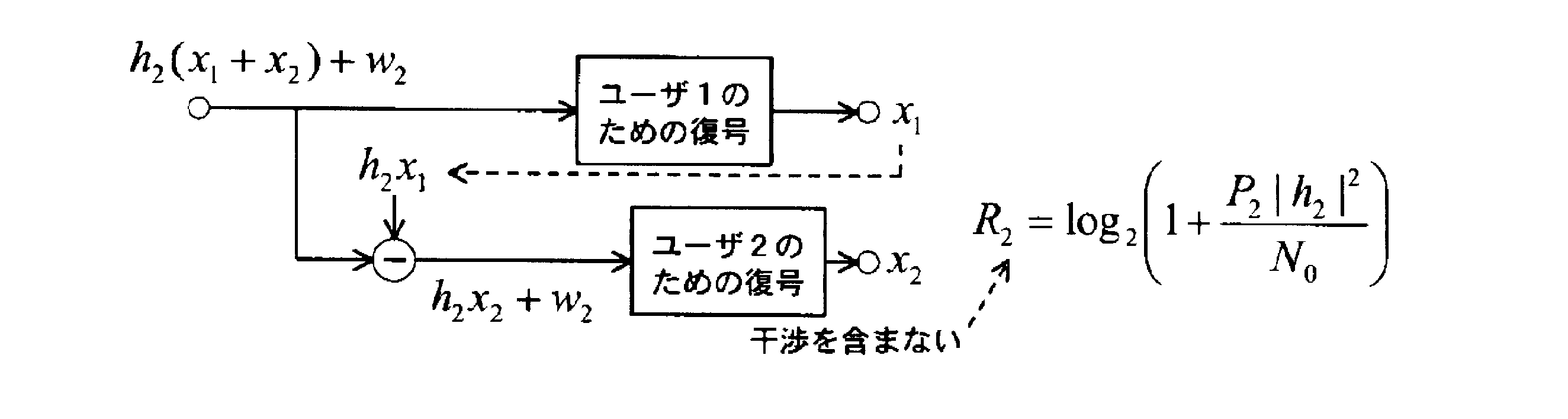
このように、移動局(ユーザ2)がセル中央に位置する場合、受信信号(R2)には、セル端に位置する移動局(ユーザ1)との干渉が含まれるが、ユーザ1と比較してSNRが良いため、ユーザ1の信号を一旦復号することによって除去し、当該信号を除去した後、ユーザ2の信号の復調/復号を実行する。
なお、このような信号処理は、上述した非特許文献1に記載されている方法と同様である。
(3)作用・効果の例
本実施形態に係る移動体通信システム1によれば、移動局200A(200B)において、非直交信号を用いることによる他の受信装置宛ての信号による干渉がキャンセルされ、干渉がキャンセルされた自装置宛ての信号と、直交信号に含まれる自装置宛ての信号との両方の信号が復調される。すなわち、直交信号と非直交信号とを用いるハイブリッド直交/非直交マルチアクセスが実現される。ハイブリッド直交/非直交マルチアクセスの場合、非直交マルチアクセスのみを用いる場合と比較して、他の受信装置宛ての信号による干渉のキャンセルに係る処理負荷が低減されるため、移動局のコスト上昇や処理遅延を抑制し得る。
本実施形態に係る移動体通信システム1によれば、移動局200A(200B)において、非直交信号を用いることによる他の受信装置宛ての信号による干渉がキャンセルされ、干渉がキャンセルされた自装置宛ての信号と、直交信号に含まれる自装置宛ての信号との両方の信号が復調される。すなわち、直交信号と非直交信号とを用いるハイブリッド直交/非直交マルチアクセスが実現される。ハイブリッド直交/非直交マルチアクセスの場合、非直交マルチアクセスのみを用いる場合と比較して、他の受信装置宛ての信号による干渉のキャンセルに係る処理負荷が低減されるため、移動局のコスト上昇や処理遅延を抑制し得る。
本実施形態では、非直交信号として多重される信号の最大数は、基地局100及び移動局200A, 200Bにおいて既知である。データ復調/復号部220の干渉キャンセラは、既知である当該信号の最大数を越えない範囲で、制御情報等によって指定された数の他装置宛ての信号による干渉を復調及びキャンセルする。このため、移動局200A, 200Bにおいて、復調/復号に要する遅延時間を一定の範囲内に収まるように設計することが可能になる。
本実施形態では、非直交信号として多重される信号の複数の移動局それぞれまでのパスロスに基づいて、当該パスロスの差が大きくなるように非直交信号として多重される信号が、当該複数の移動局にスケジューリングされる。このため、非直交信号として多重される信号間のSNRのばらつきが大きくなり易く、他装置宛ての信号による干渉の除去が容易になる。
[第2実施形態]
上述した第1実施形態では、図3(a)に示す無線リソース(直交リソース及び非直交リソース)の割り当てイメージに基づく動作について主に説明したが、第2実施形態では、図3(b)に示す無線リソースの割り当てイメージに基づく動作について、上述した第1実施形態と異なる部分について、主に説明する。
上述した第1実施形態では、図3(a)に示す無線リソース(直交リソース及び非直交リソース)の割り当てイメージに基づく動作について主に説明したが、第2実施形態では、図3(b)に示す無線リソースの割り当てイメージに基づく動作について、上述した第1実施形態と異なる部分について、主に説明する。
図3(b)に示す無線リソースの割り当てイメージの場合、移動局200Aの物理チャネル分離部210(無線信号受信部)は、互いに直交する複数の無線リソースである直交リソースのうち、直交リソースの一部または全てを用いて送信された互いに直交しない複数の非直交信号が含まれた無線信号を受信する。
また、データ復調/復号部220の干渉キャンセラは、受信した無線信号の中から、移動局200A宛ての非直交信号が含まれる直交リソースを抽出する。さらに、干渉キャンセラは、抽出した直交リソースに含まれる複数の非直交信号の中から、他の移動局(移動局200B)宛ての無線信号を復調及びキャンセルすることによって、移動局200A宛ての非直交信号を抽出する。さらに、データ復調/復号部220は、干渉キャンセラによって抽出された移動局200A宛ての非直交信号を復調する。
このように、図3(b)に示す無線リソースの割り当てイメージに基づくハイブリッド直交/非直交マルチアクセスの場合でも、非直交マルチアクセスのみを用いる場合と比較して、他の移動局(受信装置)宛ての信号による干渉のキャンセルに係る処理負荷が低減されるため、移動局のコスト上昇や処理遅延を抑制し得る。
[その他の実施形態]
上述したように、本発明の一実施形態を通じて本発明の内容を開示したが、この開示の一部をなす論述及び図面は、本発明を限定するものであると理解すべきではない。この開示から当業者には様々な代替実施の形態が明らかとなろう。
上述したように、本発明の一実施形態を通じて本発明の内容を開示したが、この開示の一部をなす論述及び図面は、本発明を限定するものであると理解すべきではない。この開示から当業者には様々な代替実施の形態が明らかとなろう。
例えば、基地局100は、直交マルチアクセスとして利用される無線リソースと、非直交マルチアクセスとして利用される無線リソースとを示す割り当てマップを移動局200A, 200Bに送信するようにしてもよい。
図7及び図8は、直交マルチアクセス及び非直交マルチアクセスの割り当てマップの例を示す。具体的には、図7は、無線リソースブロック(Resource block)単位の割り当てマップの例を示し、図8は、無線リソースエレメント(Resource element)単位の割り当てマップの例を示す。
次に、このような割り当てマップの生成方法について説明する。上述した実施形態では、移動局(ユーザ)間のSNRの違いを利用することによって、非直交アクセス技術を用いつつ、無線通信システムの全容量改善及びユーザ間フェアネスの向上を図っている。
ここで、ユーザ間にSNRの違いがない場合、直交アクセス技術が最適となる。基地局100は、SNRの違いの度合いに応じて、直交マルチアクセスまたは非直交マルチアクセスによってデータを送信するResource blockまたはResource elementの割合を決定する。
基地局100は、SNRの違いの度合いに応じて、直交マルチアクセスによる割り当て部分(該当するResource block(RB)またはResource element(RE))、及び非直交マルチアクセス部分(該当するRBまたはRE)の割り当てマップ(図7及び図8参照)を移動局200A, 200Bに対して送信する。
具体的には、基地局100は、各移動局からフィードバックされるCSI情報に基づいて、SNRの違いの度合いを判定する。基地局100は、SNRの違いの度合いが比較的大きいRB, REについて非直交マルチアクセスとして処理し、SNRの違いの度合いが比較的小さいRB, REについて直交マルチアクセスとして処理する。基地局100は、このような処理結果に基づく割り当てマップを移動局200A, 200Bに対して送信する。なお、割り当てマップの内容の通知手段としては、DL grantやRRC signalingなどを用いればよい。
また、上述した本発明の実施形態では、基地局100から移動局200A, 200Bへの下り方向における例について説明したが、本発明に係るハイブリッド直交/非直交マルチアクセスは、上り方向に適用してもよい。また、本発明は、基地局と移動局との間に限らず、基地局間の無線通信に適用してもよい。
このように、本発明は、ここでは記載していない様々な実施の形態などを含むことは勿論である。したがって、本発明の技術的範囲は、上述の説明から妥当な請求の範囲に係る発明特定事項によってのみ定められるものである。
なお、日本国特許出願第2011-114023号(2011年5月20日出願)、日本国特許出願第2011-227137号(2011年10月14日出願)の全内容が、参照により、本願明細書に組み込まれている。
本発明の特徴によれば、コスト上昇や処理遅延を抑制しつつ、非直交マルチアクセスを利用し得る受信装置、送信装置及び無線通信方法を提供することができる。
1…移動体通信システム
100…基地局
110…符号化/データ変調部
120…基地局スケジューラ
130…ハイブリッド直交/非直交多重部
140…制御信号生成部
150…制御信号リソース割当部
160…物理チャネル多重部
200A, 200B…移動局
210…物理チャネル分離部
220…データ復調/復号部
230…目的ユーザ制御信号検出部
240…干渉ユーザ制御信号検出部
100…基地局
110…符号化/データ変調部
120…基地局スケジューラ
130…ハイブリッド直交/非直交多重部
140…制御信号生成部
150…制御信号リソース割当部
160…物理チャネル多重部
200A, 200B…移動局
210…物理チャネル分離部
220…データ復調/復号部
230…目的ユーザ制御信号検出部
240…干渉ユーザ制御信号検出部
Claims (8)
- 互いに直交する複数の直交信号と、互いに直交しない複数の非直交信号とが含まれた無線信号を受信する無線信号受信部と、
前記無線信号受信部が受信した無線信号に含まれる直交信号を用いて、複数の非直交信号の中から、他の受信装置宛ての無線信号を復調及びキャンセルすることによって、当該受信装置宛ての非直交信号を抽出する干渉キャンセル部と、
前記直交信号に含まれる当該受信装置宛ての信号と、前記干渉キャンセル部によって抽出された当該受信装置宛ての非直交信号とを復調する復調部と
を備える受信装置。 - 互いに直交する複数の無線リソースである直交リソースのうち、前記直交リソースの一部または全てを用いて送信された互いに直交しない複数の非直交信号が含まれた無線信号を受信する無線信号受信部と、
前記無線信号受信部が受信した無線信号の中から、前記受信装置宛ての非直交信号が含まれる直交リソースを抽出し、抽出した前記直交リソースに含まれる複数の非直交信号の中から、他の受信装置宛ての無線信号を復調及びキャンセルすることによって、当該受信装置宛ての非直交信号を抽出する干渉キャンセル部と、
前記干渉キャンセル部によって抽出された当該受信装置宛ての非直交信号を復調する復調部と
を備える受信装置。 - 前記非直交信号として多重される信号の最大数は、当該受信装置において既知であり、
前記干渉キャンセル部は、既知である前記非直交信号の最大数を超えない範囲で、他の受信装置宛ての無線信号を復調及びキャンセルする請求項1または2に記載の受信装置。 - 互いに直交する複数の直交信号と、互いに直交しない複数の非直交信号とが含まれた無線信号をセル内に位置する複数の受信装置に向けて送信する無線信号送信部と、
前記非直交信号として多重される信号の前記複数の受信装置それぞれまでのパスロスに基づいて、前記パスロスの差が大きくなるように前記非直交信号として多重される信号を、前記複数の受信装置にスケジューリングするスケジューリング部と
を備える送信装置。 - 前記無線信号送信部は、前記受信装置が前記受信装置宛ての非直交信号が含まれる直交リソースを抽出するために必要な情報を、前記直交信号を用いて前記受信装置に送信する請求項4に記載の送信装置。
- 前記非直交信号として多重される信号の最大数は、前記送信装置及び前記受信装置において既知であり、
前記受信装置が前記他の受信装置宛ての信号を復調及びキャンセルするために必要な制御信号を前記受信装置に送信する制御信号送信部を備える請求項4に記載の送信装置。 - 通信装置が、互いに直交する複数の直交信号と、互いに直交しない複数の非直交信号とが含まれた無線信号を受信するステップと、
前記通信装置が、受信した無線信号に含まれる直交信号を用いて、複数の非直交信号の中から、他の受信装置宛ての無線信号を復調及びキャンセルすることによって、当該受信装置宛ての非直交信号を抽出するステップと、
前記通信装置が、前記直交信号に含まれる当該受信装置宛ての信号と、前記抽出するステップにおいて抽出された当該受信装置宛ての非直交信号とを復調するステップと
を含む無線通信方法。 - 通信装置が、互いに直交する複数の無線リソースである直交リソースのうち、前記直交リソースの一部または全てを用いて送信された互いに直交しない複数の非直交信号が含まれた無線信号を受信するステップと、
前記通信装置が、受信した無線信号の中から、前記受信装置宛ての非直交信号が含まれる直交リソースを抽出し、抽出した前記直交リソースに含まれる複数の非直交信号の中から、他の受信装置宛ての無線信号を復調及びキャンセルすることによって、当該受信装置宛ての非直交信号を抽出するステップと、
前記通信装置が、抽出された当該受信装置宛ての非直交信号を復調するステップと
を含む無線通信方法。
Priority Applications (3)
| Application Number | Priority Date | Filing Date | Title |
|---|---|---|---|
| US14/118,790 US9438282B2 (en) | 2011-05-20 | 2012-05-17 | Receiver, transmitter and radio communication method |
| CN201280019697.6A CN103493380B (zh) | 2011-05-20 | 2012-05-17 | 接收装置、发送装置以及无线通信方法 |
| US15/223,182 US9941912B2 (en) | 2011-05-20 | 2016-07-29 | Receiver, transmitter and radio communication method |
Applications Claiming Priority (4)
| Application Number | Priority Date | Filing Date | Title |
|---|---|---|---|
| JP2011-114023 | 2011-05-20 | ||
| JP2011114023 | 2011-05-20 | ||
| JP2011-227137 | 2011-10-14 | ||
| JP2011227137A JP5869836B2 (ja) | 2011-05-20 | 2011-10-14 | 受信装置、送信装置及び無線通信方法 |
Related Child Applications (2)
| Application Number | Title | Priority Date | Filing Date |
|---|---|---|---|
| US14/118,790 A-371-Of-International US9438282B2 (en) | 2011-05-20 | 2012-05-17 | Receiver, transmitter and radio communication method |
| US15/223,182 Division US9941912B2 (en) | 2011-05-20 | 2016-07-29 | Receiver, transmitter and radio communication method |
Publications (1)
| Publication Number | Publication Date |
|---|---|
| WO2012161079A1 true WO2012161079A1 (ja) | 2012-11-29 |
Family
ID=47217157
Family Applications (1)
| Application Number | Title | Priority Date | Filing Date |
|---|---|---|---|
| PCT/JP2012/062645 Ceased WO2012161079A1 (ja) | 2011-05-20 | 2012-05-17 | 受信装置、送信装置及び無線通信方法 |
Country Status (4)
| Country | Link |
|---|---|
| US (2) | US9438282B2 (ja) |
| JP (1) | JP5869836B2 (ja) |
| CN (1) | CN103493380B (ja) |
| WO (1) | WO2012161079A1 (ja) |
Cited By (2)
| Publication number | Priority date | Publication date | Assignee | Title |
|---|---|---|---|---|
| JP2014131202A (ja) * | 2012-12-28 | 2014-07-10 | Ntt Docomo Inc | 無線基地局、ユーザ端末、無線通信方法、及び無線通信システム |
| WO2019216212A1 (ja) * | 2018-05-10 | 2019-11-14 | ソニー株式会社 | 通信装置、通信方法、及び通信プログラム |
Families Citing this family (33)
| Publication number | Priority date | Publication date | Assignee | Title |
|---|---|---|---|---|
| JP5869836B2 (ja) | 2011-05-20 | 2016-02-24 | 株式会社Nttドコモ | 受信装置、送信装置及び無線通信方法 |
| JP5864200B2 (ja) | 2011-05-20 | 2016-02-17 | 株式会社Nttドコモ | 受信装置、送信装置及び無線通信方法 |
| JP6207637B2 (ja) * | 2011-05-20 | 2017-10-04 | 株式会社Nttドコモ | 受信装置、送信装置及び無線通信方法 |
| JP5900884B2 (ja) * | 2012-02-17 | 2016-04-06 | シャープ株式会社 | 制御局装置、および無線通信システム |
| JP6214878B2 (ja) * | 2013-01-31 | 2017-10-18 | 株式会社Nttドコモ | ユーザ装置、基地局、干渉低減方法、及び干渉低減制御情報通知方法 |
| JP2015050575A (ja) * | 2013-08-30 | 2015-03-16 | 株式会社Nttドコモ | 無線基地局、ユーザ端末及び送信電力制御方法 |
| JP6374166B2 (ja) * | 2014-01-17 | 2018-08-15 | 株式会社Nttドコモ | 無線基地局、ユーザ端末及び無線通信方法 |
| JP6254019B2 (ja) * | 2014-02-28 | 2017-12-27 | 株式会社Nttドコモ | 無線基地局、ユーザ端末、無線通信方法及び無線通信システム |
| JP6313095B2 (ja) | 2014-04-01 | 2018-04-18 | 株式会社Nttドコモ | 基地局 |
| US9712272B2 (en) | 2014-06-02 | 2017-07-18 | Intel IP Corporation | User equipment and method for dynamic non-orthogonal multiple access communication |
| US10051634B2 (en) * | 2014-06-10 | 2018-08-14 | Qualcomm Incorporated | Devices and methods for facilitating non-orthogonal wireless communications |
| JP2016066887A (ja) | 2014-09-24 | 2016-04-28 | 富士通株式会社 | 基地局装置及びリソース割当方法 |
| US10555314B2 (en) * | 2014-10-07 | 2020-02-04 | Hfi Innovation Inc. | Signaling of network-assisted intra-cell interference cancellation and suppression |
| CN105634664A (zh) * | 2014-11-07 | 2016-06-01 | 中兴通讯股份有限公司 | 一种下行非正交多址接入时的解码方法及装置 |
| CN105743824A (zh) * | 2014-12-09 | 2016-07-06 | 中兴通讯股份有限公司 | 一种非正交用户设备间的干扰处理及信令通知方法和装置 |
| JP6380071B2 (ja) * | 2014-12-11 | 2018-08-29 | ソニー株式会社 | 通信制御装置、無線通信装置、通信制御方法及び無線通信方法 |
| US9831958B2 (en) | 2014-12-30 | 2017-11-28 | Mediatek Inc. | Resource allocation for superposition coding |
| US9893843B2 (en) | 2014-12-30 | 2018-02-13 | Mediatek Inc. | Rate matching and soft channel bits storage for superposition coding |
| US9680578B2 (en) | 2014-12-30 | 2017-06-13 | Mediatek Inc. | Soft packet combining for superposition coding |
| EP3258626A4 (en) | 2015-01-14 | 2018-10-31 | Sharp Kabushiki Kaisha | Base station device and terminal device |
| CN107251461B (zh) | 2015-02-12 | 2020-07-14 | 华为技术有限公司 | 用于非正交传输信令的设备与方法 |
| JP6598146B2 (ja) * | 2015-02-20 | 2019-10-30 | 株式会社国際電気通信基礎技術研究所 | 無線通信装置、無線モジュールおよびそれらを備える無線通信システム |
| US10389477B2 (en) * | 2015-03-15 | 2019-08-20 | Qualcomm Incorporated | Devices and methods for facilitating a non-orthogonal underlay in wireless communications systems |
| CN107431555B (zh) * | 2015-03-31 | 2020-01-10 | 索尼公司 | 装置 |
| JP6586762B2 (ja) | 2015-04-07 | 2019-10-09 | ソニー株式会社 | 受信装置、送信装置、受信方法、送信方法及びプログラム |
| US10439770B2 (en) | 2015-05-14 | 2019-10-08 | Sharp Kabushiki Kaisha | Base station device and terminal device |
| CN107926032A (zh) * | 2015-09-11 | 2018-04-17 | 富士通株式会社 | 信息传输装置、方法以及通信系统 |
| JP6555410B2 (ja) | 2016-03-09 | 2019-08-07 | 富士通株式会社 | 基地局、移動局、通信システムおよび通信方法 |
| US20170289920A1 (en) * | 2016-03-29 | 2017-10-05 | Futurewei Technologies, Inc. | Method and Apparatus for Resource and Power Allocation in Non-Orthogonal Uplink Transmissions |
| US10237035B2 (en) | 2016-06-15 | 2019-03-19 | Electronics And Telecommunications Research Institute | Operation method of communication node supporting superposition transmission in cellular communication system |
| JP6609357B2 (ja) * | 2018-08-22 | 2019-11-20 | 株式会社Nttドコモ | 無線基地局及びユーザ端末 |
| US12003290B2 (en) * | 2020-04-16 | 2024-06-04 | Qualcomm Incorporated | Techniques for switching orthogonal and non-orthogonal sequence based noncoherent uplink control transmissions |
| CN114339884B (zh) * | 2021-12-27 | 2024-04-26 | 绍兴文理学院 | 一种两用户双向传输协作非正交多址接入方法和系统 |
Citations (3)
| Publication number | Priority date | Publication date | Assignee | Title |
|---|---|---|---|---|
| JP2002111542A (ja) * | 2000-09-27 | 2002-04-12 | Matsushita Electric Ind Co Ltd | 通信端末装置及び復調方法 |
| JP2009522916A (ja) * | 2006-01-27 | 2009-06-11 | サムスン エレクトロニクス カンパニー リミテッド | 移動通信システムにおけるハイブリッド多重アクセス装置及び方法 |
| JP2009530974A (ja) * | 2006-03-24 | 2009-08-27 | アルカテル−ルーセント ユーエスエー インコーポレーテッド | Ofdmaトーン干渉キャンセルの方法 |
Family Cites Families (6)
| Publication number | Priority date | Publication date | Assignee | Title |
|---|---|---|---|---|
| JP2009010752A (ja) * | 2007-06-28 | 2009-01-15 | Ntt Docomo Inc | 移動通信システム、基地局装置及び方法 |
| JP5366494B2 (ja) | 2007-10-10 | 2013-12-11 | パナソニック株式会社 | マルチキャリア送信装置 |
| CN101453735B (zh) * | 2007-11-30 | 2011-08-24 | 北京大学 | 梳状谱码分多址与ofdm复合系统及其调制、解调方法 |
| WO2009081514A1 (ja) * | 2007-12-25 | 2009-07-02 | Panasonic Corporation | 無線通信装置、無線通信システム及び無線通信方法 |
| TWI429207B (zh) * | 2009-06-21 | 2014-03-01 | Ablaze Wireless Inc | 基地台之變換域多用戶偵測及干擾抑制裝置 |
| JP5869836B2 (ja) | 2011-05-20 | 2016-02-24 | 株式会社Nttドコモ | 受信装置、送信装置及び無線通信方法 |
-
2011
- 2011-10-14 JP JP2011227137A patent/JP5869836B2/ja not_active Expired - Fee Related
-
2012
- 2012-05-17 WO PCT/JP2012/062645 patent/WO2012161079A1/ja not_active Ceased
- 2012-05-17 US US14/118,790 patent/US9438282B2/en not_active Expired - Fee Related
- 2012-05-17 CN CN201280019697.6A patent/CN103493380B/zh active Active
-
2016
- 2016-07-29 US US15/223,182 patent/US9941912B2/en active Active
Patent Citations (3)
| Publication number | Priority date | Publication date | Assignee | Title |
|---|---|---|---|---|
| JP2002111542A (ja) * | 2000-09-27 | 2002-04-12 | Matsushita Electric Ind Co Ltd | 通信端末装置及び復調方法 |
| JP2009522916A (ja) * | 2006-01-27 | 2009-06-11 | サムスン エレクトロニクス カンパニー リミテッド | 移動通信システムにおけるハイブリッド多重アクセス装置及び方法 |
| JP2009530974A (ja) * | 2006-03-24 | 2009-08-27 | アルカテル−ルーセント ユーエスエー インコーポレーテッド | Ofdmaトーン干渉キャンセルの方法 |
Cited By (3)
| Publication number | Priority date | Publication date | Assignee | Title |
|---|---|---|---|---|
| JP2014131202A (ja) * | 2012-12-28 | 2014-07-10 | Ntt Docomo Inc | 無線基地局、ユーザ端末、無線通信方法、及び無線通信システム |
| WO2019216212A1 (ja) * | 2018-05-10 | 2019-11-14 | ソニー株式会社 | 通信装置、通信方法、及び通信プログラム |
| US11533148B2 (en) | 2018-05-10 | 2022-12-20 | Sony Corporation | Communication device and communication method |
Also Published As
| Publication number | Publication date |
|---|---|
| US20160336981A1 (en) | 2016-11-17 |
| JP2013009288A (ja) | 2013-01-10 |
| US9941912B2 (en) | 2018-04-10 |
| CN103493380B (zh) | 2015-03-25 |
| JP5869836B2 (ja) | 2016-02-24 |
| US9438282B2 (en) | 2016-09-06 |
| US20140086372A1 (en) | 2014-03-27 |
| CN103493380A (zh) | 2014-01-01 |
Similar Documents
| Publication | Publication Date | Title |
|---|---|---|
| JP5869836B2 (ja) | 受信装置、送信装置及び無線通信方法 | |
| JP5864199B2 (ja) | 受信装置、送信装置及び無線通信方法 | |
| JP5864200B2 (ja) | 受信装置、送信装置及び無線通信方法 | |
| JP5785845B2 (ja) | 受信装置、送信装置及び無線通信方法 | |
| EP4319413A2 (en) | Over-the-air signal assisted interference cancellation or suppression | |
| EP4383633A1 (en) | Method for operating terminal in wireless communication system, and device using same method | |
| WO2015025847A1 (ja) | 無線基地局、中継局及び無線通信方法 | |
| US11690120B2 (en) | Method and apparatus for a sub-band transpose repeater | |
| JP6088596B2 (ja) | 受信装置、送信装置及び無線通信方法 | |
| JP6207637B2 (ja) | 受信装置、送信装置及び無線通信方法 | |
| JP6207582B2 (ja) | 受信装置、送信装置及び無線通信方法 | |
| JP2018074594A (ja) | 無線基地局、中継局及び無線通信方法 | |
| JP6207581B2 (ja) | 受信装置、送信装置及び無線通信方法 | |
| EP4668933A1 (en) | Operation method of apparatus in wireless communication system, and apparatus using same method | |
| EP4712631A1 (en) | Operation method of device in wireless communication system, and device using method | |
| EP4693969A1 (en) | Operating method of apparatus in wireless communication system, and apparatus using same method | |
| EP4668935A1 (en) | Device operation method in wireless communication system, and device using same |
Legal Events
| Date | Code | Title | Description |
|---|---|---|---|
| 121 | Ep: the epo has been informed by wipo that ep was designated in this application |
Ref document number: 12789872 Country of ref document: EP Kind code of ref document: A1 |
|
| WWE | Wipo information: entry into national phase |
Ref document number: 14118790 Country of ref document: US |
|
| NENP | Non-entry into the national phase |
Ref country code: DE |
|
| 122 | Ep: pct application non-entry in european phase |
Ref document number: 12789872 Country of ref document: EP Kind code of ref document: A1 |