WO2012161047A1 - 心血管リスク評価装置 - Google Patents
心血管リスク評価装置 Download PDFInfo
- Publication number
- WO2012161047A1 WO2012161047A1 PCT/JP2012/062504 JP2012062504W WO2012161047A1 WO 2012161047 A1 WO2012161047 A1 WO 2012161047A1 JP 2012062504 W JP2012062504 W JP 2012062504W WO 2012161047 A1 WO2012161047 A1 WO 2012161047A1
- Authority
- WO
- WIPO (PCT)
- Prior art keywords
- oxygen saturation
- blood pressure
- blood oxygen
- unit
- blood
- Prior art date
Links
Images


Classifications
-
- A—HUMAN NECESSITIES
- A61—MEDICAL OR VETERINARY SCIENCE; HYGIENE
- A61B—DIAGNOSIS; SURGERY; IDENTIFICATION
- A61B5/00—Measuring for diagnostic purposes; Identification of persons
- A61B5/72—Signal processing specially adapted for physiological signals or for diagnostic purposes
- A61B5/7271—Specific aspects of physiological measurement analysis
- A61B5/7275—Determining trends in physiological measurement data; Predicting development of a medical condition based on physiological measurements, e.g. determining a risk factor
-
- A—HUMAN NECESSITIES
- A61—MEDICAL OR VETERINARY SCIENCE; HYGIENE
- A61B—DIAGNOSIS; SURGERY; IDENTIFICATION
- A61B5/00—Measuring for diagnostic purposes; Identification of persons
- A61B5/02—Detecting, measuring or recording pulse, heart rate, blood pressure or blood flow; Combined pulse/heart-rate/blood pressure determination; Evaluating a cardiovascular condition not otherwise provided for, e.g. using combinations of techniques provided for in this group with electrocardiography or electroauscultation; Heart catheters for measuring blood pressure
- A61B5/0205—Simultaneously evaluating both cardiovascular conditions and different types of body conditions, e.g. heart and respiratory condition
-
- A—HUMAN NECESSITIES
- A61—MEDICAL OR VETERINARY SCIENCE; HYGIENE
- A61B—DIAGNOSIS; SURGERY; IDENTIFICATION
- A61B5/00—Measuring for diagnostic purposes; Identification of persons
- A61B5/02—Detecting, measuring or recording pulse, heart rate, blood pressure or blood flow; Combined pulse/heart-rate/blood pressure determination; Evaluating a cardiovascular condition not otherwise provided for, e.g. using combinations of techniques provided for in this group with electrocardiography or electroauscultation; Heart catheters for measuring blood pressure
- A61B5/021—Measuring pressure in heart or blood vessels
- A61B5/022—Measuring pressure in heart or blood vessels by applying pressure to close blood vessels, e.g. against the skin; Ophthalmodynamometers
-
- A—HUMAN NECESSITIES
- A61—MEDICAL OR VETERINARY SCIENCE; HYGIENE
- A61B—DIAGNOSIS; SURGERY; IDENTIFICATION
- A61B5/00—Measuring for diagnostic purposes; Identification of persons
- A61B5/145—Measuring characteristics of blood in vivo, e.g. gas concentration, pH value; Measuring characteristics of body fluids or tissues, e.g. interstitial fluid, cerebral tissue
- A61B5/1455—Measuring characteristics of blood in vivo, e.g. gas concentration, pH value; Measuring characteristics of body fluids or tissues, e.g. interstitial fluid, cerebral tissue using optical sensors, e.g. spectral photometrical oximeters
- A61B5/14551—Measuring characteristics of blood in vivo, e.g. gas concentration, pH value; Measuring characteristics of body fluids or tissues, e.g. interstitial fluid, cerebral tissue using optical sensors, e.g. spectral photometrical oximeters for measuring blood gases
- A61B5/14552—Details of sensors specially adapted therefor
-
- A—HUMAN NECESSITIES
- A61—MEDICAL OR VETERINARY SCIENCE; HYGIENE
- A61B—DIAGNOSIS; SURGERY; IDENTIFICATION
- A61B5/00—Measuring for diagnostic purposes; Identification of persons
- A61B5/48—Other medical applications
- A61B5/4806—Sleep evaluation
- A61B5/4809—Sleep detection, i.e. determining whether a subject is asleep or not
-
- A—HUMAN NECESSITIES
- A61—MEDICAL OR VETERINARY SCIENCE; HYGIENE
- A61B—DIAGNOSIS; SURGERY; IDENTIFICATION
- A61B5/00—Measuring for diagnostic purposes; Identification of persons
- A61B5/48—Other medical applications
- A61B5/4806—Sleep evaluation
- A61B5/4818—Sleep apnoea
-
- A—HUMAN NECESSITIES
- A61—MEDICAL OR VETERINARY SCIENCE; HYGIENE
- A61B—DIAGNOSIS; SURGERY; IDENTIFICATION
- A61B5/00—Measuring for diagnostic purposes; Identification of persons
- A61B5/74—Details of notification to user or communication with user or patient ; user input means
- A61B5/742—Details of notification to user or communication with user or patient ; user input means using visual displays
-
- G—PHYSICS
- G16—INFORMATION AND COMMUNICATION TECHNOLOGY [ICT] SPECIALLY ADAPTED FOR SPECIFIC APPLICATION FIELDS
- G16H—HEALTHCARE INFORMATICS, i.e. INFORMATION AND COMMUNICATION TECHNOLOGY [ICT] SPECIALLY ADAPTED FOR THE HANDLING OR PROCESSING OF MEDICAL OR HEALTHCARE DATA
- G16H40/00—ICT specially adapted for the management or administration of healthcare resources or facilities; ICT specially adapted for the management or operation of medical equipment or devices
- G16H40/60—ICT specially adapted for the management or administration of healthcare resources or facilities; ICT specially adapted for the management or operation of medical equipment or devices for the operation of medical equipment or devices
- G16H40/63—ICT specially adapted for the management or administration of healthcare resources or facilities; ICT specially adapted for the management or operation of medical equipment or devices for the operation of medical equipment or devices for local operation
-
- G—PHYSICS
- G16—INFORMATION AND COMMUNICATION TECHNOLOGY [ICT] SPECIALLY ADAPTED FOR SPECIFIC APPLICATION FIELDS
- G16H—HEALTHCARE INFORMATICS, i.e. INFORMATION AND COMMUNICATION TECHNOLOGY [ICT] SPECIALLY ADAPTED FOR THE HANDLING OR PROCESSING OF MEDICAL OR HEALTHCARE DATA
- G16H50/00—ICT specially adapted for medical diagnosis, medical simulation or medical data mining; ICT specially adapted for detecting, monitoring or modelling epidemics or pandemics
- G16H50/30—ICT specially adapted for medical diagnosis, medical simulation or medical data mining; ICT specially adapted for detecting, monitoring or modelling epidemics or pandemics for calculating health indices; for individual health risk assessment
-
- G—PHYSICS
- G16—INFORMATION AND COMMUNICATION TECHNOLOGY [ICT] SPECIALLY ADAPTED FOR SPECIFIC APPLICATION FIELDS
- G16H—HEALTHCARE INFORMATICS, i.e. INFORMATION AND COMMUNICATION TECHNOLOGY [ICT] SPECIALLY ADAPTED FOR THE HANDLING OR PROCESSING OF MEDICAL OR HEALTHCARE DATA
- G16H50/00—ICT specially adapted for medical diagnosis, medical simulation or medical data mining; ICT specially adapted for detecting, monitoring or modelling epidemics or pandemics
- G16H50/70—ICT specially adapted for medical diagnosis, medical simulation or medical data mining; ICT specially adapted for detecting, monitoring or modelling epidemics or pandemics for mining of medical data, e.g. analysing previous cases of other patients
Definitions
- the present invention relates to a cardiovascular risk evaluation apparatus that evaluates a cardiovascular risk of a subject, and more particularly, to a cardiovascular risk evaluation apparatus that evaluates a cardiovascular risk from the relationship between blood oxygen saturation and blood pressure of the subject. .
- Obstructive sleep apnea imposes a tremendous pressure load on the cardiovascular system due to a rapid rise in blood pressure associated with a decrease in blood oxygen saturation during an apnea attack.
- This pressure load is considered to be a promising candidate mechanism for cardiovascular events such as cerebrovascular disorder and myocardial infarction, and assessing the cardiovascular risk of patients based on information on this increase in blood pressure is the management of various diseases Is extremely important.
- Patent Document 1 Japanese Patent Application Laid-Open Publication No. 2003-208867
- Patent Document 2 Japanese Patent Laid-Open No. 62-155829 proposes a method for automatically measuring blood pressure when the blood oxygen saturation is lowered.
- JP 2009-66269 A JP-A-62-155829
- Patent Document 1 it is determined that the risk of occurrence of a cardiovascular event is higher as the time integral value (IAD) of the blood oxygen saturation level lower than the threshold value is larger.
- IAD time integral value
- Patent Document 2 Japanese Patent Application Laid-Open No. 62-155829
- an object of the present invention is to provide a cardiovascular risk evaluation apparatus capable of acquiring an index for cardiovascular risk evaluation in consideration of a pressure load for lowering blood oxygen saturation.
- a cardiovascular risk evaluation apparatus is a method for measuring blood oxygen saturation measured in a hypoxic period in which a subject's blood oxygen saturation is lower than a threshold, and measurement of the blood oxygen saturation.
- a hypoxic acquisition means for acquiring a measurement result including blood pressure measured occasionally, a blood oxygen saturation measured in a non-hypoxic period of a subject's blood oxygen saturation, and the blood oxygen saturation
- Based on non-hypoxic acquisition means for acquiring a measurement result including blood pressure measured at the time of measurement, a measurement result acquired by the low-oxygen acquisition means, and a measurement result acquired by the non-hypoxic acquisition means From the relationship between blood oxygen saturation and blood pressure, an index acquisition unit that acquires an index for cardiovascular risk evaluation of a subject, and a unit that outputs the acquired index to an output unit.
- the blood oxygen saturation measured during the hypoxic period of the subject and the blood pressure measured when the blood oxygen saturation is measured, and the non-hypoxic period Cardiovascular in consideration of pressure load from the relationship between blood oxygen saturation and blood pressure based on the blood oxygen saturation measured and the measurement results including the blood pressure measured when the blood oxygen saturation is measured
- An index for risk assessment can be obtained.
- FIG. 1 shows the hardware configuration of the cardiovascular risk evaluation apparatus 1 according to the present embodiment
- FIGS. 2 to 4 show the overall functions of the cardiovascular risk evaluation apparatus 1 and the configuration of each function.
- 5 to 7 show an example of the contents of the memory unit 39 of FIG. 1
- FIG. 8 shows a processing flowchart
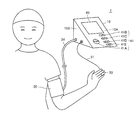
- FIG. 9 shows how the cardiovascular risk evaluation apparatus 1 is used during measurement. Shown schematically with appearance.
- cardiovascular risk assessment apparatus 1 connects main body 10, a blood pressure measurement site of a subject, for example, a cuff 20 for wrapping around the upper arm, and main body 10 and cuff 20. And a sensor unit 50 to be attached to a measurement site of blood oxygen saturation, for example, a fingertip.
- the main body 10 and the sensor unit 50 are electrically connected via the wiring 51.
- a display unit 40 for displaying measurement results and an operation unit 41 for receiving an instruction input from a user are arranged.
- the operation unit 41 is operated to input, for example, a switch 41A that is operated to switch the power ON / OFF, a switch 41B that is operated to identify the subject, and measurement start and stop instructions. It includes a switch 41C and a switch 41D, and a switch 41E operated to input an instruction to read and display information based on past measurement data.
- the display part 40 is comprised by displays, such as a liquid crystal, for example.
- the air tube 24 and the wiring 51 described above are connected to the left side surface 10 ⁇ / b> B of the main body 10.
- the cuff 20 of the cardiovascular risk evaluation apparatus 1 includes an air bag 21 in which air is contained.
- the air bladder 21 is connected to an air system 25 built in the main body 10 via an air tube 24.
- the air system 25 includes a capacitance type pressure sensor 32 for detecting the pressure in the air bladder 21 (hereinafter referred to as “cuff pressure”), a pump 33 for supplying air to the air bladder 21, an air And an exhaust valve 34 that is opened and closed to exhaust or seal the air in the bag 21.
- the sensor unit 50 corresponds to a so-called pulse oximeter, and detects at least two light emitting elements 501 and 502 that emit infrared rays having different central wavelengths, and the amount of infrared rays emitted from the light emitting elements 501 and 502 and transmitted through the measurement site.
- the main body 10 includes a light emitting element driving circuit 52 that controls the light emitting operation of the light emitting elements 501 and 502, and an amplification / AD conversion circuit 53 that amplifies the output of the light receiving element 503 for each wavelength and performs AD (Analog / Digital) conversion.
- a light emitting element driving circuit 52 that controls the light emitting operation of the light emitting elements 501 and 502
- an amplification / AD conversion circuit 53 that amplifies the output of the light receiving element 503 for each wavelength and performs AD (Analog / Digital) conversion.
- the main unit 10 includes a CPU (Central Processing Unit) 1000 for performing various arithmetic processes, a power supply unit 42, a ROM (Read Only Memory) for storing various data and programs, a RAM (Random Access Memory), and a nonvolatile memory.
- Various recording media such as a memory unit 39 including a memory, a timer 43, a communication I / F (interface) 44 for controlling communication between the information processing device 46 and the CPU 1000, and an SD memory card (Secure Digital memory card) are detachable.
- an external I / F 45 for accessing the mounted recording medium under the control of the CPU 1000.
- the information processing device 46 is not limited as long as it is a device having a data output function such as a communication function, a data processing function, and a display.
- the main body 10 includes an oscillation circuit 35, a pump drive circuit 36 for driving the pump 33, and a valve drive circuit 37 for driving the exhaust valve 34 in association with the air system 25.
- the pump drive circuit 36 controls the drive of the pump 33 based on a control signal given from the CPU 1000.
- the valve drive circuit 37 performs opening / closing control of the exhaust valve 34 based on a control signal given from the CPU 1000.
- the capacitance value of the pressure sensor 32 changes due to the cuff pressure, and a signal indicating the capacitance value is output after being amplified by an amplifier (amplification circuit) built in the pressure sensor 32.
- the oscillation circuit 35 outputs a signal having an oscillation frequency corresponding to the capacitance value of the pressure sensor 32 to the CPU 1000 based on the output signal of the pressure sensor 32.
- the CPU 1000 detects the cuff pressure by converting the signal obtained from the oscillation circuit 35 into a pressure.
- the power supply unit 42 supplies power to the CPU 1000 in response to a power ON instruction from the operation unit 41.
- the CPU 1000 outputs the supplied power to each unit.
- FIG. 2 shows a functional configuration of the CPU 1000 of the cardiovascular risk evaluation apparatus 1 together with its peripheral circuits.
- CPU 1000 includes a blood pressure measurement unit 100, an oxygen saturation measurement control unit 200, a hypoxia acquisition unit 300, and an average calculation unit 401 that calculates an average of blood oxygen saturation.
- Unit 400 storage processing unit 500 for storing data in memory unit 39, reading unit 600 for reading data from memory unit 39, index detection unit 700 for detecting an index for cardiovascular risk evaluation, display A display information generation unit 800 having a VRAM (Video Random Access Memory) for generating display information of the unit 40, a display control unit 850 having a digital signal processing circuit for display control of the display unit 40, and the operation unit 41.
- An operation receiving unit 900 that outputs an instruction (command) corresponding to the operation for receiving the user's operation to each unit is included.
- Each of these units is configured using program data and / or circuit modules stored in the memory unit 39.
- the blood pressure measurement unit 100 includes a cuff pressure control unit 101 and a blood pressure calculation unit 102.
- the cuff pressure control unit 110 adjusts the cuff pressure of the cuff 20 by controlling the operations of the pump drive circuit 36 and the valve drive circuit 37.
- the blood pressure measurement unit 100 receives the output signal of the oscillation circuit 35, detects the oscillation frequency of the input signal, and converts the detected oscillation frequency into a pressure value signal.
- An HPF unit that extracts and outputs a volume pulse wave signal by processing the pressure value signal by HPF (High Pass Filter), and an absolute pressure signal (hereinafter cuff) by processing the pressure value signal by LPF (Low Pass Filter).
- LPF unit that extracts and outputs a pressure signal).
- the blood pressure calculation unit 102 receives the volume pulse wave signal extracted by the HPF unit, and processes the input volume pulse wave signal according to a predetermined procedure, whereby a systolic blood pressure SBP (systolic blood pressure) and a minimum The blood pressure (diastolic blood pressure DBP (Diastolic blood pressure)) is calculated, and the pulse rate is calculated according to a known procedure.
- SBP systolic blood pressure
- DBP Diastolic blood pressure
- the blood pressure calculation procedure follows the oscillometric method of measuring the blood pressure based on the cuff pressure detected in the process of pressurizing the measurement site to a predetermined pressure with the cuff 20 and then gradually reducing the pressure. It is not limited.
- the oxygen saturation measurement control unit 200 includes a clock 201 that outputs a clock signal synchronized with the time output by the timer 43, a pulse wave amplitude calculation unit 202, a pulse wave amplitude comparison unit 203, and an oxygen saturation calculation unit 204.
- the oxygen saturation measurement control unit 200 controls the light emitting element driving circuit 52 at a timing specified by the clock 201 so that the light emitting elements 501 and 502 alternately emit infrared rays having two wavelengths. Infrared light that has passed through the measurement site of the subject and reached the light receiving element 503 is detected by the light receiving element 503. At this time, the arterial volume change accompanying the pulsation of the internal artery pressure is reflected in the output of the light receiving element 503 as a change in the amount of transmitted light. This is called a photoelectric pulse wave (hereinafter simply “pulse wave”).
- pulse wave a photoelectric pulse wave
- pulse wave signal When the pulse wave signal is sent from the light receiving element 503 to the amplification / AD conversion circuit 53, pulse waves having different wavelengths are separately amplified / AD converted at the timing specified by the clock 201.
- the AD-converted pulse wave signal is sent to the pulse wave amplitude calculation unit 202.
- the pulse wave amplitude calculation unit 202 detects the pulse wave obtained from the amplification / AD conversion circuit 53 in units of one beat, and calculates the amplitude of each pulse wave.
- the pulse wave amplitude comparison unit 203 obtains the ratio of the pulse wave amplitudes of the two wavelengths calculated by the pulse wave amplitude calculation unit 202.
- the oxygen saturation calculation unit 204 calculates the blood oxygen saturation based on the calculated pulse wave amplitude ratio.
- the oxygen saturation calculation unit 204 calculates the blood oxygen saturation of the subject based on the relationship between the pulse wave amplitude ratio and the oxygen saturation stored in advance in the memory unit 39.
- the blood oxygen saturation is calculated, for example, every 5 seconds, and the calculated blood oxygen saturation data is recorded together with the pointer i in the internal memory of the CPU 1000.
- the light emitting elements 501, 502, the light receiving element 503, the light emitting element driving circuit 52, the amplification / AD conversion circuit 53, and the oxygen saturation measurement control unit 200 are oxygen saturation for measuring blood oxygen saturation. Functions as a degree measurement unit.
- the configuration of the oxygen saturation measurement unit and the blood oxygen saturation calculation method employed in the cardiovascular risk evaluation apparatus 1 according to the present invention are not limited to the above.
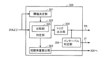
- the hypoxic acquisition unit 300 includes a trigger signal TR (hereinafter referred to as a trigger signal TR) based on outputs from a threshold determination unit 301, a determination unit 302 including a comparison unit 305, a low oxygen amount calculation unit 303, and a determination unit 302.
- Trigger output section 304 for outputting (TR) and interval determination section 306 for outputting measurement start instruction signal IT while monitoring trigger TR.
- the trigger output unit 304 causes the blood pressure measurement unit 100 to start blood pressure measurement by outputting a trigger TR based on the comparison result of the comparison portion 305.
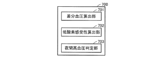
- the index detection unit 700 includes a differential blood pressure calculation unit 701, a hypoxia sensitivity calculation unit 702, and a nocturnal hypertension determination unit 703.
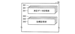
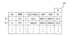
- the memory unit 39 includes a measurement data storage unit 391 and an index storage unit 392 corresponding to each subject.
- the measurement data storage unit 391 stores measurement data in a database format. Specifically, ID data for uniquely identifying the corresponding subject and one or more records R are stored. Each record R includes No data for uniquely identifying the record, time data indicating the measurement time, and blood oxygen saturation measured (or calculated) at the time (low oxygen level Sp or average MSp described later) ), Systolic blood pressure SBP, diastolic blood pressure DBP and pulse rate PL, and flag F. The flag F is for identifying whether the blood oxygen saturation of the record R is the low oxygen amount Sp or the average MSp.
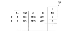
- index storage unit 392 stores cardiovascular evaluation index data in the form of a database. Specifically, ID data for uniquely identifying the corresponding subject and one or more records R are stored. Each record R is calculated by the No data for uniquely identifying the record, the time data indicating the measurement time, the differential blood pressure DF calculated by the differential blood pressure calculation unit 701 at the time, and the hypoxia sensitivity calculation unit 702.
- the determination value NH indicating the result of determination by the hypoxia-sensitive OS and the nocturnal hypertension determination unit 703 is included.
- the determination value NH is set to “1” when it is determined that the subject falls under nocturnal hypertension from the systolic blood pressure SBP measured at that time, and is set to “0” when it is determined that it does not correspond. .
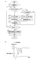
- the measurement process will be described with reference to the flowchart of FIG.
- the program according to this flowchart is stored in a predetermined storage area of the memory unit 39 in advance, and the function according to the process flowchart is realized by the CPU 1000 reading and executing the program from the memory unit 39.
- the graph of FIG. 8B shows the change in the blood oxygen saturation of the subject over time in the measurement process of FIG. In the graph, the elapsed time is taken on the horizontal axis, and the blood oxygen saturation (%) is taken on the vertical axis.
- the operation reception unit 900 receives the operation and outputs a measurement start instruction according to the operation.
- the switch 41B is operated by the subject, and the ID data of the subject is input.
- the oxygen saturation measurement control unit 200 starts calculating blood oxygen saturation.
- the blood oxygen saturation is calculated, for example, every 5 seconds and is recorded in the internal memory of the CPU 1000 as the blood oxygen saturation SpO2 (i).
- the subject is generally not in normal breathing, that is, in the state of OSA.
- the degree SpO2 (i) refers to a sufficient amount of oxygen.
- the threshold determining unit 301 of the hypoxic acquisition unit 300 determines whether or not the blood oxygen saturation indicates a low oxygen amount, that is, a threshold TH for determining an apneic attack (step S1). Specifically, the average value of the blood oxygen saturation SpO2 (i) stored in the internal memory for the predetermined period (for example, 1 minute) after the measurement instruction is input is calculated, and 10 is calculated from the average value. The subtracted value is determined as the threshold value TH (step S1). This determination method is merely an example, and is not limited to this. Thus, the threshold TH for apnea attack determination may be determined for each subject, or the threshold TH that is commonly applied to the subject may be determined in advance.
- the determined threshold value TH is given to the determination unit 302.
- the determination unit 302 determines whether or not the blood oxygen saturation level SpO2 (i) is less than the threshold value TH (step S3).
- the comparison unit 305 reads the blood oxygen saturation SpO2 (i) from the internal memory according to the measurement order, that is, according to the value of the pointer i, and reads the blood oxygen saturation SpO2 (i) and the threshold value TH. Compare Based on the comparison result, the determination unit 302 determines whether the blood oxygen saturation SpO2 (i) is less than or equal to the threshold value TH. If it is determined that it is less than (YES in step S3), the trigger output unit 304 is instructed to output the trigger TR, and the low oxygen amount calculation unit 303 is instructed to calculate.
- the trigger output unit 304 outputs the trigger TR to the blood pressure measurement unit 100 in response to the instruction.
- the blood pressure measurement unit 100 starts blood pressure measurement according to the apnea attack in response to the trigger TR.
- the internal pressure of the cuff 20 is increased to a predetermined pressure, and then gradually reduced.
- Blood pressure measurement data (systolic blood pressure SBP, diastolic blood pressure DBP, and pulse rate PL) are calculated based on the cuff pressure detected in the decompression process.
- the blood pressure measurement may be performed during the pressurization process.
- the calculated blood pressure measurement data is output to the storage processing unit 500 (step S15).
- the low oxygen amount calculation unit 303 calculates a low oxygen amount Sp (i) during an apnea attack in response to a given calculation instruction, and outputs the calculated low oxygen amount Sp (i) to the storage processing unit 500. (Step S17).
- the low oxygen amount Sp (i) indicates the lowest value during one apnea attack of the blood oxygen saturation SpO2 (i) in the internal memory.
- the low oxygen amount calculation unit 303 calculates the blood oxygen saturation SpO2 (i) stored when the calculation instruction is input and the previous time. The lowest value is determined using the measured (stored) blood oxygen saturation SpO2 (i-1). For example, the lowest value of blood oxygen saturation SpO2 (i), that is, the low oxygen amount Sp (i) is detected at the star mark in the graph of FIG. 8B.
- the low oxygen amount Sp (i) which is the lowest value during the apnea attack, is acquired a plurality of times. And the blood pressure measurement data measured when each low oxygen amount Sp (i) is measured are acquired.
- the storage processing unit 500 associates the given blood pressure measurement data, the low oxygen amount Sp (i), and the current time data T output from the timer 43, and the measurement data storage unit 391 corresponding to the ID data of the subject. Is stored as a record R (step S19). “0” is set in the flag F of the record R stored at this time to indicate that the measurement data is in the low oxygen period.
- the CPU 1000 determines whether or not the measurement end switch 41D of the operation unit 41 has been operated by the subject (step S21).
- the index detection unit 700 calculates an index for cardiovascular risk evaluation such as hypoxia sensitivity according to the instruction signal from the operation reception unit 900,
- the data is output to the storage processing unit 500.
- the storage processing unit 500 stores the record R in which the input index is associated with the time data from the timer 43 in the index storage unit 392 corresponding to the ID data of the subject (step S23).
- the display information generation unit 800 reads the record R from the storage unit 500, generates image information representing the index of the record R, and outputs it to the display control unit 850.
- the display control unit 850 displays the image information on the display unit 40 (step S25). Thereafter, the process ends.
- the acquired index is output to the display unit 40, but may be output to an output unit such as a printer or an audio unit.
- step S21 If it is determined that the switch 41D is not operated (NO in step S21), the process returns to step S3, and the subsequent processes are similarly repeated. Details of the index calculation procedure will be described later.
- step S3 determines whether the subject's condition is a non-hypoxic period that is not a hypoxic period of an apnea attack (step S5).
- the interval determination unit 306 monitors the trigger TR, and the period during which the trigger TR is not output from the measurement start time or the output time of the previous measurement start instruction signal IT is a fixed period (for example, 30 Min) It is determined based on the output of the timer 43 whether or not it has continued. If it is determined that the period has continued (YES in step S5), IT is output to the blood pressure measurement unit 100 and the non-hypoxic acquisition unit 400.
- a fixed period for example, 30 Min
- the interval blood pressure measurement is performed every 30 minutes, but is limited to 30 minutes. Not. Further, the interval may be set variably.
- the blood pressure measurement unit 100 starts blood pressure measurement in response to the input of the instruction signal IT, outputs the acquired blood pressure measurement data to the storage processing unit 500 (step S7), and the non-hypoxic time acquisition unit 400
- the average calculation unit 401 reads the blood oxygen saturation SpO2 (i) recently stored (for example, stored in the past one minute) from the internal memory, and reads the blood
- the average MSp (i) is calculated from the oxygen saturation SpO2 (i), and the calculated average MSp (i) is output to the storage processing unit 500 (step S9).
- the storage processing unit 500 associates the given blood pressure measurement data with the average MSp (i) and the current time data T output from the timer 43, and the measurement data corresponding to the ID data of the subject in the memory unit 39 Store as a record R in the storage unit 391 (step S19).
- the average MSp (i) is regarded as the blood oxygen saturation SpO2 (i) measured when the blood pressure measurement data is measured. Although the average value is used here, it may be a representative value, and may be a median value, a mode value, or the like.
- the flag F of the record R stored at this time is set to “1” to indicate that it is measurement data (average MSp (i)) during the non-hypoxic period. Thereafter, the process proceeds to step S21.
- step S21 is started without starting the blood pressure measurement and calculating the average MSp (i) of the blood oxygen saturation SpO2 (i).
- the CPU 1000 has a function of determining whether the subject is sleeping based on the switch operation of the operation unit 41 received by the operation reception unit 900, but the determination method is not limited thereto.
- the determination may be made using a timer.
- a sensor that detects attachment / detachment to the measurement site may be attached to the cuff 20 or the sensor unit 50, and the determination may be made based on the output of the sensor.
- the body temperature of the subject may be measured, and the determination may be made based on a change in body temperature, focusing on the decrease in body temperature during sleep.
- the low oxygen amount which is the blood oxygen saturation measured in the low oxygen period in which the blood oxygen saturation SpO2 (i) of the subject is smaller than the threshold TH by the hypoxic acquisition unit 300 One or more measurement results including Sp (i) and blood pressure measured at the time of measuring the blood oxygen saturation are acquired. Further, the blood pressure measured during the non-hypoxic period when the blood oxygen saturation SpO2 (i) of the subject is equal to or higher than the threshold value TH and the blood measured at the time of the blood measurement by the non-hypoxic acquisition unit 400 One or more measurement results including medium oxygen saturation (average MSp (i)) are obtained.
- the index detection unit 700 calculates an index using the measurement result acquired in this way.
- step S23 the index detection unit 700 reads the record R from the measurement data storage unit 391 of the subject in the memory unit 39, and calculates the index based on the read data of the record R. That is, the blood oxygen saturation based on the data of one or more measurement result records R acquired by the hypoxic acquisition unit 300 and the data of one or more measurement result records R acquired by the non-hypoxic acquisition unit 400 An index for cardiovascular risk assessment of the subject is obtained from the relationship between blood pressure and blood pressure.
- the differential blood pressure calculation unit 701 calculates the difference between the blood pressure measured in the non-hypoxic state and the blood pressure measured in the hypoxic state based on the above relationship as an index for cardiovascular risk evaluation.
- the hypoxia sensitivity calculation unit 702 acquires the hypoxia sensitivity of the subject based on the above relationship as an index for cardiovascular risk evaluation.
- Hypoxia sensitivity represents the degree of increase in blood pressure for a fixed amount of oxygen saturation.
- the nocturnal hypertension determination unit 703 determines whether or not the blood pressure of the subject corresponds to nocturnal hypertension based on the above relationship.
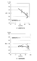
- the hypoxic sensitivity calculation unit 702 Based on the data of the record R read from the measurement data storage unit 391, the hypoxic sensitivity calculation unit 702, for example, as shown in the graph of FIG. 10 (blood pressure on the vertical axis and blood oxygen saturation SpO2 on the horizontal axis), for example, From the systolic blood pressure SBP associated with the blood oxygen saturation (low oxygen amount Sp (i) and mean MSp (i)), an equation of a regression line (referred to as a relational expression) showing the relationship between the two is calculated. From FIG. 10, a relational expression indicating a difference between a measurement result acquired by the low oxygen acquisition unit 300 and a measurement result acquired by the non-hypoxic acquisition unit 400 is obtained.
- the hypoxia sensitivity calculation unit 702 calculates the slope of the straight line indicated by the relational expression as hypoxia sensitivity.
- the data in FIG. 10 indicates data obtained from two subjects by the inventors' experiments according to the flowchart in FIG.
- the method generally used statistically can apply the method of calculating the relational expression of a regression line.
- (A) of FIG. 10 illustrates the case where the hypoxia sensitivity is high, and (B) illustrates the case where it is low.
- Hypoxia sensitivity is determined by the average value of trigger blood pressure (systolic blood pressure SBP associated with hypoxia Sp (i)) and the interval blood pressure (systolic phase associated with mean MSp (i).
- hypoxia sensitivity (the hypoxia sensitivity value and the scatter diagram shown in FIG. 10) calculated in this way is displayed on the display unit via the display information generation unit 800 and the display control unit 850.
- hypoxia sensitivity may be displayed as an absolute value, or may be displayed in a format that is compared with a normal value, and indicates the degree of the disease state (the degree of cardiovascular risk (the likelihood of stroke)). It is good also as a level display.
- the inventors of the subject in FIG. 10A have a higher hypoxia sensitivity value than the subject in FIG. 10B, and the blood pressure increases with a decrease in blood oxygen saturation.
- hypoxia sensitivity increases, the pressure load on the cardiovascular system during apnea attacks is expected to increase, and the risk to the cardiovascular system is expected to increase. Obtained knowledge.
- hypoxia sensitivity is a good index for evaluating (estimating) cardiovascular risk in sleep apnea patients.
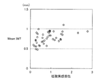
- the differential blood pressure calculation unit 701 is based on the data of the record R read from the measurement data storage unit 391, as shown in the graph of FIG. 12 (blood pressure on the vertical axis and blood oxygen saturation SpO2 on the horizontal axis), as shown in FIG.
- a linear relational expression is calculated from the systolic blood pressure SBP associated with the degree of saturation (low oxygen amount Sp (i) and average MSp (i)) in the same manner as described above.
- FIG. 12 shows straight lines L1 and L2 measured by an experiment according to the flowchart of FIG. 8A for two subjects. This straight line is similar to the straight line shown in FIG.
- the average value of the trigger blood pressure (systolic blood pressure SBP associated with the low oxygen amount Sp (i)) and the contraction associated with the interval blood pressure (mean MSp (i)). It indicates a straight line connecting two points of the mean values of the blood pressure SBP).
- the differential blood pressure calculation unit 701 calculates a difference between the trigger blood pressure and the interval blood pressure as a differential blood pressure DF from a linear relational expression.
- the differential blood pressure DF (L1) of the straight line L1 having a large slope (hypoxic sensitivity) indicated by the relational expression is large, and the differential blood pressure DF (L2) of the straight line L2 having a small slope (hypoxic sensitivity) is small. From this, it can be seen that hypoxia sensitivity and differential blood pressure have a correlation.
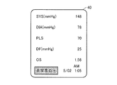
- FIG. 13 shows a display example of the measurement result on the display unit 40.
- the display unit 40 displays systolic blood pressure, diastolic blood pressure, pulse rate, differential blood pressure, and hypoxia sensitivity values as measurement results, and whether or not it corresponds to nocturnal hypertension.
- the mark is displayed.
- the systolic blood pressure, the diastolic blood pressure, and the pulse rate refer to the average value during the measurement period, but may be the systolic blood pressure, the diastolic blood pressure, and the pulse rate when the maximum systolic blood pressure is measured.
- the display unit 40 also displays the measurement times of these measurement data. In the display, advice on drug prescription based on the index may be given together with the index.
- FIG. 14 shows an example of the information processing apparatus 46.
- the information processing device 46 has a function as a data processing device that processes measurement data obtained by the cardiovascular risk evaluation device 1.
- the information processing device 46 communicates with an external device including the CPU 461, a memory 462 for storing program data, a hard disk 463, a display unit 464, an operation unit 465 that accepts user operations, a printer 466, and the cardiovascular risk evaluation device 1.
- Various recording media such as a communication I / F (Interface) 467 and an SD memory card 47 are detachably mounted, and an external I / F 468 for accessing the mounted recording media under the control of the CPU 461 is provided.
- the data measured by the cardiovascular risk evaluation apparatus 1 is received via the communication I / F 467.
- the SD memory card 47 in which the measurement data is recorded is attached to the external I / F 468 and acquired by reading from the SD memory card 47.
- the measurement data received or acquired in this way is stored in the memory 462 or the like.
- the CPU 461 includes an index detection unit 461A that calculates the various indexes described above and a display information generation unit 461B that generates display information of the calculated index based on the measurement data stored in the memory 462.
- the generated display information is displayed on the display unit 464.
- the display information may be transmitted to the cardiovascular risk evaluation apparatus 1 and displayed on the display unit 40 of the cardiovascular risk evaluation apparatus 1.
- measurement data can be obtained, indicators can be calculated, and displayed by an external device of the cardiovascular risk evaluation device 1, for example, a doctor's information processing device 46.
- the method according to the flowchart of FIG. 8A performed by the cardiovascular risk evaluation apparatus 1 in the present invention can be provided as a program.
- a program can be recorded on a computer-readable recording medium such as a flexible disk attached to the computer, a CD-ROM, a ROM, a RAM, and a memory card, and provided as a program product.
- the program can be provided by being recorded on a recording medium such as a hard disk built in the computer.
- a program can also be provided by downloading via a network.
- the program can be supplied to the cardiovascular risk evaluation apparatus 1 having the CPU 1000 and having the function of a computer using various recording media such as the SD memory card 47.
- the CPU 1000 reads and executes the program stored in the recording medium via the external I / F 45.
- the information processing apparatus 46 can be supplied with the program using various recording media such as the SD memory card 47.
- the CPU 461 reads and executes the program stored in the recording medium via the external I / F 48.
- the provided program product is installed in a program storage unit such as a hard disk, and is read and executed by the CPU.
- the program product includes the program itself and a recording medium on which the program is recorded.
- the interval blood pressure measurement is performed in a period in which the trigger blood pressure measurement is not performed while the trigger blood pressure measurement is performed.
- the measurement data at the time of non-hypoxia by the interval blood pressure measurement is separately acquired. Also good. That is, measurement data at the time of non-hypoxia may be acquired in a resting state in which the subject is awakened.
- the threshold value TH may be set to a low value for a subject having high hypoxia sensitivity, and may be set to a high value for a subject having low hypoxia sensitivity.
- the cardiovascular risk evaluation apparatus 1 is a type that is placed on a desk, but may be a wrist-worn type as shown in FIG.
- the blood pressure measurement site is the wrist portion
- the cuff 20 is wound around the wrist
- the main body 10 and the cuff 20 are configured integrally.
- Various switches corresponding to the operation unit 41 are provided on the surface of the casing of the main body unit 10.
- Cardiovascular risk evaluation device 46 Information processing device, 50 Sensor unit, 100 Blood pressure measurement unit, 200 Oxygen saturation measurement control unit, 204 Oxygen saturation calculation unit, 300 Hypoxia acquisition unit, 301 Threshold determination unit, 302 determination Unit, 303 low oxygen amount calculation unit, 304 trigger output unit, 305 comparison unit, 306 interval determination unit, 391 measurement data storage unit, 392 indicator storage unit, 400 non-hypoxia acquisition unit, 401 average calculation unit, 461A, 700 Index detection unit, 461B, 800 display information generation unit, 701 differential blood pressure calculation unit, 702 hypoxia sensitivity calculation unit, 703 nocturnal hypertension determination unit.
Landscapes
- Health & Medical Sciences (AREA)
- Life Sciences & Earth Sciences (AREA)
- Engineering & Computer Science (AREA)
- Public Health (AREA)
- Medical Informatics (AREA)
- Biomedical Technology (AREA)
- Physics & Mathematics (AREA)
- General Health & Medical Sciences (AREA)
- Pathology (AREA)
- Heart & Thoracic Surgery (AREA)
- Biophysics (AREA)
- Molecular Biology (AREA)
- Surgery (AREA)
- Animal Behavior & Ethology (AREA)
- Veterinary Medicine (AREA)
- Physiology (AREA)
- Cardiology (AREA)
- Primary Health Care (AREA)
- Epidemiology (AREA)
- Data Mining & Analysis (AREA)
- Vascular Medicine (AREA)
- Databases & Information Systems (AREA)
- Spectroscopy & Molecular Physics (AREA)
- Optics & Photonics (AREA)
- Anesthesiology (AREA)
- Artificial Intelligence (AREA)
- Computer Vision & Pattern Recognition (AREA)
- Psychiatry (AREA)
- Signal Processing (AREA)
- Ophthalmology & Optometry (AREA)
- Pulmonology (AREA)
- General Business, Economics & Management (AREA)
- Business, Economics & Management (AREA)
- Measurement Of The Respiration, Hearing Ability, Form, And Blood Characteristics Of Living Organisms (AREA)
- Measuring Pulse, Heart Rate, Blood Pressure Or Blood Flow (AREA)
Priority Applications (3)
| Application Number | Priority Date | Filing Date | Title |
|---|---|---|---|
| US14/116,928 US8897849B2 (en) | 2011-05-24 | 2012-05-16 | Cardiovascular risk evaluation apparatus |
| CN201280022352.6A CN103533885B (zh) | 2011-05-24 | 2012-05-16 | 心血管风险评价装置 |
| DE112012002203.3T DE112012002203T5 (de) | 2011-05-24 | 2012-05-16 | Kardiovaskuläres-Risiko-Analysegerät |
Applications Claiming Priority (2)
| Application Number | Priority Date | Filing Date | Title |
|---|---|---|---|
| JP2011-115845 | 2011-05-24 | ||
| JP2011115845A JP5693377B2 (ja) | 2011-05-24 | 2011-05-24 | 心血管リスク評価装置 |
Publications (2)
| Publication Number | Publication Date |
|---|---|
| WO2012161047A1 true WO2012161047A1 (ja) | 2012-11-29 |
| WO2012161047A9 WO2012161047A9 (ja) | 2013-10-17 |
Family
ID=47217127
Family Applications (1)
| Application Number | Title | Priority Date | Filing Date |
|---|---|---|---|
| PCT/JP2012/062504 WO2012161047A1 (ja) | 2011-05-24 | 2012-05-16 | 心血管リスク評価装置 |
Country Status (5)
| Country | Link |
|---|---|
| US (1) | US8897849B2 (zh) |
| JP (1) | JP5693377B2 (zh) |
| CN (1) | CN103533885B (zh) |
| DE (1) | DE112012002203T5 (zh) |
| WO (1) | WO2012161047A1 (zh) |
Families Citing this family (11)
| Publication number | Priority date | Publication date | Assignee | Title |
|---|---|---|---|---|
| JP5991100B2 (ja) * | 2012-09-13 | 2016-09-14 | オムロンヘルスケア株式会社 | 脈拍測定装置、脈拍測定方法、および脈拍測定プログラム |
| JP6202485B2 (ja) * | 2013-01-11 | 2017-09-27 | 株式会社タニタ | 生体情報管理モジュール、睡眠計、およびシステム |
| US10022053B2 (en) * | 2013-02-22 | 2018-07-17 | Cloud Dx, Inc. | Simultaneous multi-parameter physiological monitoring device with local and remote analytical capability |
| JP2014217707A (ja) * | 2013-05-11 | 2014-11-20 | 株式会社 ライフインターフェイス | 生体情報計測装置及び生体情報計測システム |
| US20160081602A1 (en) * | 2014-09-18 | 2016-03-24 | Covidien Lp | Methods and systems for providing power to light sources of a physiological monitor |
| JP2016198206A (ja) * | 2015-04-08 | 2016-12-01 | 浜松ホトニクス株式会社 | 血中酸素状態のモニタリング装置及びモニタリング方法 |
| JP6790936B2 (ja) | 2017-03-14 | 2020-11-25 | オムロンヘルスケア株式会社 | 血圧データ処理装置、血圧データ処理方法、およびプログラム |
| JP6851866B2 (ja) * | 2017-03-14 | 2021-03-31 | オムロン株式会社 | 情報処理装置および情報処理プログラム |
| US10980488B2 (en) | 2018-09-20 | 2021-04-20 | Pacific Delta Llc | Determination of blood pressure measurement confidence using variable monitor inaccuracy |
| CN110432878A (zh) * | 2019-08-26 | 2019-11-12 | 浙江纳雄医疗器械有限公司 | 一种缺氧耐受分析装置及其测量方法 |
| CN110960226B (zh) * | 2019-12-09 | 2022-07-12 | 海脉医疗科技(天津)有限公司 | 一种组织血氧数据监测电路、方法及装置 |
Citations (1)
| Publication number | Priority date | Publication date | Assignee | Title |
|---|---|---|---|---|
| JP2009039352A (ja) * | 2007-08-09 | 2009-02-26 | Omron Healthcare Co Ltd | 血圧測定装置 |
Family Cites Families (8)
| Publication number | Priority date | Publication date | Assignee | Title |
|---|---|---|---|---|
| JPS62155829A (ja) | 1985-12-27 | 1987-07-10 | コーリン電子株式会社 | 自動血圧測定装置 |
| JP4025220B2 (ja) * | 2003-03-03 | 2007-12-19 | ▲苅▼尾 七臣 | 血圧計および心血管系疾病リスク分析プログラム |
| JP2005237472A (ja) * | 2004-02-24 | 2005-09-08 | 七臣 ▲苅▼尾 | 血圧測定装置 |
| JP2007125079A (ja) * | 2005-11-01 | 2007-05-24 | Omron Healthcare Co Ltd | 電子血圧計 |
| JP5178106B2 (ja) | 2007-09-14 | 2013-04-10 | 佳史 高田 | 血中酸素飽和度測定装置、心血管イベントのリスク予測装置、診断装置、及び高感度crp高値のリスク予測装置 |
| EP2369982A1 (en) * | 2008-12-30 | 2011-10-05 | Endothelix, Inc. | Cardiohealth methods and apparatus |
| EP2673721A1 (en) * | 2011-02-13 | 2013-12-18 | Masimo Corporation | Medical characterization system |
| US20140073888A1 (en) * | 2012-09-07 | 2014-03-13 | Nellcor Puritan Bennett Llc | Non-invasive method for monitoring autoregulation |
-
2011
- 2011-05-24 JP JP2011115845A patent/JP5693377B2/ja active Active
-
2012
- 2012-05-16 DE DE112012002203.3T patent/DE112012002203T5/de active Pending
- 2012-05-16 CN CN201280022352.6A patent/CN103533885B/zh active Active
- 2012-05-16 US US14/116,928 patent/US8897849B2/en active Active
- 2012-05-16 WO PCT/JP2012/062504 patent/WO2012161047A1/ja active Application Filing
Patent Citations (1)
| Publication number | Priority date | Publication date | Assignee | Title |
|---|---|---|---|---|
| JP2009039352A (ja) * | 2007-08-09 | 2009-02-26 | Omron Healthcare Co Ltd | 血圧測定装置 |
Non-Patent Citations (2)
| Title |
|---|
| KAZUOMI KARIO: "Suiminji Mukokyu Shokogun ni Tomonau Koketsuatsu", JOURNAL OF BLOOD PRESSURE, vol. 16, no. 3, 2009, pages 239 - 243 * |
| T. PENZEL ET AL.: "Ambulatory Recording of Sleep Apnea Using Perpheral Arterial Tonometry", IEEE ENGINEERING IN MEDICINE AND BIOLOGY 26TH ANNUAL CONFERENCE, vol. 5, 1 September 2004 (2004-09-01), pages 3856 - 3859 * |
Also Published As
| Publication number | Publication date |
|---|---|
| JP2012239807A (ja) | 2012-12-10 |
| WO2012161047A9 (ja) | 2013-10-17 |
| CN103533885A (zh) | 2014-01-22 |
| CN103533885B (zh) | 2015-06-17 |
| US20140088386A1 (en) | 2014-03-27 |
| DE112012002203T5 (de) | 2014-06-12 |
| JP5693377B2 (ja) | 2015-04-01 |
| US8897849B2 (en) | 2014-11-25 |
Similar Documents
| Publication | Publication Date | Title |
|---|---|---|
| JP5693377B2 (ja) | 心血管リスク評価装置 | |
| JP5098721B2 (ja) | 血圧測定装置、血圧導出プログラムおよび血圧導出方法 | |
| JP4702216B2 (ja) | 電子血圧計およびその制御方法 | |
| JP5410210B2 (ja) | 1回拍出量の呼吸性変動解析装置におけるアーチファクト除去方法、血液量測定装置及びアーチファクト除去プログラム | |
| US7270636B2 (en) | Apparatus and method for pulse detection | |
| US20190159722A1 (en) | Biological information analysis device, system, and program | |
| EP3270772B1 (en) | Method and apparatus for measuring blood pressure | |
| US8888707B2 (en) | Blood pressure measurement apparatus | |
| WO2011122125A1 (ja) | 血圧測定装置 | |
| JP2005237472A (ja) | 血圧測定装置 | |
| WO2012033232A1 (ja) | 胸部装着式血圧計 | |
| JP2010220638A (ja) | 血圧情報測定装置 | |
| JP6508064B2 (ja) | 血圧推定装置、血圧推定方法、血圧測定装置、及び、血圧推定プログラム | |
| WO2010098195A1 (ja) | 血圧測定装置、血圧測定プログラムプロダクト、および、血圧測定制御方法 | |
| JP5200956B2 (ja) | 血圧情報測定装置 | |
| CN112426141A (zh) | 血压检测方法、装置以及电子设备 | |
| US20120029366A1 (en) | Blood pressure detection apparatus and blood pressure detection method | |
| WO2017158909A1 (ja) | 血圧脈波測定装置 | |
| JP5092885B2 (ja) | 電子血圧計 | |
| JP6226289B2 (ja) | 循環器機能判定装置 | |
| JP2019037686A (ja) | バイタルサイン測定装置 | |
| EP3581104A1 (en) | Method, device and computer program product for estimating a compliance of a blood vessel in a subject | |
| JP2022167320A (ja) | 脈波解析装置、脈波解析方法、および脈波解析プログラム | |
| KR20220106606A (ko) | 연속적으로 혈압측정이 가능한 웨어러블 디바이스 |
Legal Events
| Date | Code | Title | Description |
|---|---|---|---|
| 121 | Ep: the epo has been informed by wipo that ep was designated in this application |
Ref document number: 12789098 Country of ref document: EP Kind code of ref document: A1 |
|
| WWE | Wipo information: entry into national phase |
Ref document number: 14116928 Country of ref document: US |
|
| WWE | Wipo information: entry into national phase |
Ref document number: 112012002203 Country of ref document: DE Ref document number: 1120120022033 Country of ref document: DE |
|
| 122 | Ep: pct application non-entry in european phase |
Ref document number: 12789098 Country of ref document: EP Kind code of ref document: A1 |