WO2012160913A1 - Dispositif de projection de lumière - Google Patents
Dispositif de projection de lumière Download PDFInfo
- Publication number
- WO2012160913A1 WO2012160913A1 PCT/JP2012/060696 JP2012060696W WO2012160913A1 WO 2012160913 A1 WO2012160913 A1 WO 2012160913A1 JP 2012060696 W JP2012060696 W JP 2012060696W WO 2012160913 A1 WO2012160913 A1 WO 2012160913A1
- Authority
- WO
- WIPO (PCT)
- Prior art keywords
- light
- projection
- unit
- range
- shadow
- Prior art date
Links
- 238000012937 correction Methods 0.000 claims description 53
- 238000001514 detection method Methods 0.000 claims description 51
- 230000003287 optical effect Effects 0.000 claims description 42
- 238000005286 illumination Methods 0.000 claims description 33
- 230000004907 flux Effects 0.000 claims description 5
- 238000009877 rendering Methods 0.000 claims description 5
- 230000001678 irradiating effect Effects 0.000 claims description 2
- 238000000034 method Methods 0.000 description 11
- 238000006243 chemical reaction Methods 0.000 description 4
- 238000010586 diagram Methods 0.000 description 4
- 238000012545 processing Methods 0.000 description 3
- 238000007796 conventional method Methods 0.000 description 2
- 230000007812 deficiency Effects 0.000 description 1
- 238000013461 design Methods 0.000 description 1
- 230000000694 effects Effects 0.000 description 1
- 238000005516 engineering process Methods 0.000 description 1
- 238000003384 imaging method Methods 0.000 description 1
- 238000012986 modification Methods 0.000 description 1
- 230000004048 modification Effects 0.000 description 1
Images


Classifications
-
- G—PHYSICS
- G02—OPTICS
- G02B—OPTICAL ELEMENTS, SYSTEMS OR APPARATUS
- G02B27/00—Optical systems or apparatus not provided for by any of the groups G02B1/00 - G02B26/00, G02B30/00
- G02B27/0025—Optical systems or apparatus not provided for by any of the groups G02B1/00 - G02B26/00, G02B30/00 for optical correction, e.g. distorsion, aberration
-
- F—MECHANICAL ENGINEERING; LIGHTING; HEATING; WEAPONS; BLASTING
- F21—LIGHTING
- F21V—FUNCTIONAL FEATURES OR DETAILS OF LIGHTING DEVICES OR SYSTEMS THEREOF; STRUCTURAL COMBINATIONS OF LIGHTING DEVICES WITH OTHER ARTICLES, NOT OTHERWISE PROVIDED FOR
- F21V33/00—Structural combinations of lighting devices with other articles, not otherwise provided for
-
- G—PHYSICS
- G01—MEASURING; TESTING
- G01J—MEASUREMENT OF INTENSITY, VELOCITY, SPECTRAL CONTENT, POLARISATION, PHASE OR PULSE CHARACTERISTICS OF INFRARED, VISIBLE OR ULTRAVIOLET LIGHT; COLORIMETRY; RADIATION PYROMETRY
- G01J1/00—Photometry, e.g. photographic exposure meter
- G01J1/42—Photometry, e.g. photographic exposure meter using electric radiation detectors
- G01J1/4228—Photometry, e.g. photographic exposure meter using electric radiation detectors arrangements with two or more detectors, e.g. for sensitivity compensation
-
- H—ELECTRICITY
- H04—ELECTRIC COMMUNICATION TECHNIQUE
- H04N—PICTORIAL COMMUNICATION, e.g. TELEVISION
- H04N9/00—Details of colour television systems
- H04N9/12—Picture reproducers
- H04N9/31—Projection devices for colour picture display, e.g. using electronic spatial light modulators [ESLM]
- H04N9/3179—Video signal processing therefor
- H04N9/3182—Colour adjustment, e.g. white balance, shading or gamut
-
- H—ELECTRICITY
- H04—ELECTRIC COMMUNICATION TECHNIQUE
- H04N—PICTORIAL COMMUNICATION, e.g. TELEVISION
- H04N9/00—Details of colour television systems
- H04N9/12—Picture reproducers
- H04N9/31—Projection devices for colour picture display, e.g. using electronic spatial light modulators [ESLM]
- H04N9/3191—Testing thereof
- H04N9/3194—Testing thereof including sensor feedback
-
- F—MECHANICAL ENGINEERING; LIGHTING; HEATING; WEAPONS; BLASTING
- F21—LIGHTING
- F21S—NON-PORTABLE LIGHTING DEVICES; SYSTEMS THEREOF; VEHICLE LIGHTING DEVICES SPECIALLY ADAPTED FOR VEHICLE EXTERIORS
- F21S2/00—Systems of lighting devices, not provided for in main groups F21S4/00 - F21S10/00 or F21S19/00, e.g. of modular construction
-
- F—MECHANICAL ENGINEERING; LIGHTING; HEATING; WEAPONS; BLASTING
- F21—LIGHTING
- F21V—FUNCTIONAL FEATURES OR DETAILS OF LIGHTING DEVICES OR SYSTEMS THEREOF; STRUCTURAL COMBINATIONS OF LIGHTING DEVICES WITH OTHER ARTICLES, NOT OTHERWISE PROVIDED FOR
- F21V23/00—Arrangement of electric circuit elements in or on lighting devices
- F21V23/04—Arrangement of electric circuit elements in or on lighting devices the elements being switches
- F21V23/0442—Arrangement of electric circuit elements in or on lighting devices the elements being switches activated by means of a sensor, e.g. motion or photodetectors
- F21V23/0464—Arrangement of electric circuit elements in or on lighting devices the elements being switches activated by means of a sensor, e.g. motion or photodetectors the sensor sensing the level of ambient illumination, e.g. dawn or dusk sensors
-
- F—MECHANICAL ENGINEERING; LIGHTING; HEATING; WEAPONS; BLASTING
- F21—LIGHTING
- F21W—INDEXING SCHEME ASSOCIATED WITH SUBCLASSES F21K, F21L, F21S and F21V, RELATING TO USES OR APPLICATIONS OF LIGHTING DEVICES OR SYSTEMS
- F21W2131/00—Use or application of lighting devices or systems not provided for in codes F21W2102/00-F21W2121/00
- F21W2131/40—Lighting for industrial, commercial, recreational or military use
- F21W2131/405—Lighting for industrial, commercial, recreational or military use for shop-windows or displays
-
- G—PHYSICS
- G01—MEASURING; TESTING
- G01J—MEASUREMENT OF INTENSITY, VELOCITY, SPECTRAL CONTENT, POLARISATION, PHASE OR PULSE CHARACTERISTICS OF INFRARED, VISIBLE OR ULTRAVIOLET LIGHT; COLORIMETRY; RADIATION PYROMETRY
- G01J1/00—Photometry, e.g. photographic exposure meter
- G01J1/10—Photometry, e.g. photographic exposure meter by comparison with reference light or electric value provisionally void
- G01J1/20—Photometry, e.g. photographic exposure meter by comparison with reference light or electric value provisionally void intensity of the measured or reference value being varied to equalise their effects at the detectors, e.g. by varying incidence angle
- G01J1/22—Photometry, e.g. photographic exposure meter by comparison with reference light or electric value provisionally void intensity of the measured or reference value being varied to equalise their effects at the detectors, e.g. by varying incidence angle using a variable element in the light-path, e.g. filter, polarising means
- G01J1/24—Photometry, e.g. photographic exposure meter by comparison with reference light or electric value provisionally void intensity of the measured or reference value being varied to equalise their effects at the detectors, e.g. by varying incidence angle using a variable element in the light-path, e.g. filter, polarising means using electric radiation detectors
- G01J1/26—Photometry, e.g. photographic exposure meter by comparison with reference light or electric value provisionally void intensity of the measured or reference value being varied to equalise their effects at the detectors, e.g. by varying incidence angle using a variable element in the light-path, e.g. filter, polarising means using electric radiation detectors adapted for automatic variation of the measured or reference value
-
- G—PHYSICS
- G03—PHOTOGRAPHY; CINEMATOGRAPHY; ANALOGOUS TECHNIQUES USING WAVES OTHER THAN OPTICAL WAVES; ELECTROGRAPHY; HOLOGRAPHY
- G03B—APPARATUS OR ARRANGEMENTS FOR TAKING PHOTOGRAPHS OR FOR PROJECTING OR VIEWING THEM; APPARATUS OR ARRANGEMENTS EMPLOYING ANALOGOUS TECHNIQUES USING WAVES OTHER THAN OPTICAL WAVES; ACCESSORIES THEREFOR
- G03B15/00—Special procedures for taking photographs; Apparatus therefor
- G03B15/02—Illuminating scene
- G03B15/06—Special arrangements of screening, diffusing, or reflecting devices, e.g. in studio
- G03B15/07—Arrangements of lamps in studios
Definitions
- the present invention relates to an optical projection device that projects light onto an object.
- a show window there is a case where it is desired to irradiate the mannequin equipped with the product with illumination light.
- Conventional techniques include irradiating the mannequin with a spotlight or controlling the shape of the irradiation light so that only the mannequin is illuminated by measuring the shape of the mannequin and the positional relationship with the lighting fixture. It was broken.
- Patent Documents 1 and 2 there are known light projection apparatuses and illumination apparatuses that can project light in a shape desired by the user by controlling the shape of the projection light.
- the present invention has been proposed in view of the above-described circumstances, and an object thereof is to provide an optical projection apparatus that can irradiate light only on an object.
- An optical projection apparatus that solves the above problem is an optical projection apparatus that projects light onto an object arranged in an arbitrary space, and the object and the back surface of the object are within a projectable range.
- a light projection means for projecting light a shadow area detection means for detecting a shadow area generated on the back of the object by the projection light projected from the light projection means, and a projection area and the shadow area of the light projection means
- a shadow area correcting means for correcting the shadow area detected by the shadow area detecting means so that the shadow area detected by the detecting means coincides on the back of the object; and the shadow area corrected by the shadow area correcting means.
- the shadow unit projects the projection light onto a range where the object exists by projecting the projection light set by the projection light setting unit onto the light projection range set by the projection range setting unit.
- the projection light setting means includes the illuminance, luminance, luminous intensity, luminous flux, color temperature, color rendering property of the projection light projected by the light projection means.
- the optical projection apparatus uses the shadow area corrected by the shadow area correction means as a first projection range, and performs a second projection on an area other than the shadow area.
- the projection light setting unit individually sets light to be projected onto the first projection range and the second projection range, and a first projection range in which an object exists in the projectable region of the light projection unit.
- the light projection unit divides the light into a second projection range where no object exists, and the light projection unit projects different light into the first projection range and the second projection range.
- the fourth aspect includes a shadow detection operation by the shadow region detection unit, a shadow region correction operation by the shadow region correction unit, and The projection range setting operation by the projection range setting means is performed at arbitrary time intervals.
- the shadow area detection unit irradiates invisible light to an area including a projectable range of the light projection unit.
- the sixth aspect is configured such that the light projection unit projects projection light from two or more positions, and the projection range setting unit includes: A projection range is set for each light projection position.
- the seventh aspect is configured such that the shadow area detection unit detects a shadow area from two or more positions, and the shadow area correction unit. Calculates a shadow region corrected for each shadow region detection position, and the projection range setting unit sets the projection range of the light projection unit by integrating the shadow regions corrected by the shadow region correction unit. It is characterized by that.
- the shadow area detecting means is composed of an optical sensor embedded in the back surface of the object.
- the ninth aspect is an illumination data generation unit that generates illumination data for projecting projection light as illumination light by the light projection unit. It is possible to adjust the generation timing of the illumination data by, and the irradiation timing of the illumination light by the light projection means.
- the light projection apparatus according to any one of the first to ninth aspects, wherein the light projection unit projects an image, and the projection light setting unit projects light from the light projection unit.
- the video is set as
- the shadow area of the object is detected, and the projection area and the shadow area of the light projection unit are corrected so as to coincide on the back surface, and the corrected shadow area is set as the light projection range. Therefore, it is possible to project the projection light to the range where the object exists. Therefore, according to the above light projection apparatus, it is possible to irradiate the projection light only on the object.
- FIG. 1 is a perspective view showing a configuration of an optical projection apparatus shown as the first embodiment of the present invention.
- FIG. 2 is a block diagram showing the configuration of the optical projection apparatus shown as the first embodiment of the present invention.
- FIG. 3 is a perspective view, a top view of a shadow region, and a front view of the light projection apparatus shown as the first embodiment of the present invention.
- FIG. 4 is a flowchart showing an operation procedure of the optical projection apparatus shown as the first embodiment of the present invention.
- FIG. 5 is a perspective view showing a configuration of an optical projection apparatus shown as the second embodiment of the present invention.
- FIG. 6 is a block diagram showing a configuration of an optical projection apparatus shown as the second embodiment of the present invention.
- FIG. 1 is a perspective view showing a configuration of an optical projection apparatus shown as the first embodiment of the present invention.
- FIG. 2 is a block diagram showing the configuration of the optical projection apparatus shown as the first embodiment of the present invention.
- FIG. 3 is a perspective view, a
- FIG. 7 is a perspective view showing another configuration of the optical projection apparatus shown as the second embodiment of the present invention.
- FIG. 8 is a perspective view showing a configuration of an optical projection apparatus shown as the third embodiment of the present invention.
- FIG. 9 is a block diagram showing a configuration of an optical projection apparatus shown as the third embodiment of the present invention.
- FIG. 10 is a perspective view showing a configuration of an optical projection apparatus shown as the fourth embodiment of the present invention.
- FIG. 11 is a block diagram showing a configuration of an optical projection apparatus shown as the fourth embodiment of the present invention.
- FIG. 12 is a perspective view showing the configuration of an optical projection apparatus shown as the fifth embodiment of the present invention.
- An optical projection apparatus shown as an embodiment of the present invention is configured as shown in FIG. 1, for example.
- This light projection apparatus projects the projection light L1 onto the irradiated object 11 arranged in an arbitrary space.
- the irradiated object 11 is assumed to be a product or a mannequin in a showroom, for example. Further, the irradiated object 11 may be deformable or movable. The irradiated object 11 is placed on the floor 12a as a background area. In addition, a back surface 12b is provided behind the irradiated object 11.
- the light projection device includes a light projection unit 1, a shadow area detection unit 2, and a control unit 3.
- the light projection unit 1 is configured such that the irradiated object 11 and the floor surface 12a and the back surface 12b as the back surface area of the irradiated object 11 are in a projectable range.
- the light projection unit 1 projects the projection light L ⁇ b> 1 onto the irradiated object 11 under the control of the control unit 3.
- the light projection unit 1 can be realized by, for example, a projector that projects illumination light or video light.
- the shadow area detection unit 2 detects the shadow area 13 generated on the floor surface 12a and the back surface 12b of the irradiated object 11 by the projection light L1 projected from the light projection unit 1. This shadow region 13 is determined by the positional relationship between the light projection unit 1 and the irradiated object 11 and the shape of the irradiated object 11. In the present embodiment, a state in which the shadow region 13 is generated on the floor surface 12a and the back surface 12b by the projection light L1 from the light projection unit 1 is illustrated.
- the shadow area detection unit 2 can be realized by a camera or the like that acquires image data using the floor 12a and the back 12b including the shadow area 13 of the irradiated object 11 as the imaging range 2a.
- the control unit 3 controls the operations of the light projection unit 1 and the shadow area detection unit 2.
- the control unit 3 is composed of, for example, a personal computer, and the CPU executes a program for controlling the light projection unit 1 and the shadow region detection unit 2 to send control signals and the like to the light projection unit 1 and the shadow region detection unit 2. Output.
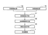
- the control unit 3 includes, as its functional configuration, a shadow area correction unit 31, a projection range setting unit 32, and a projection light setting unit 33 as shown in FIG.
- the shadow area correction means 31 acquires the shadow area 13 detected by the shadow area detector 2.
- the shadow area 13 is detected from the image data by the shadow area detector 2, for example.
- the shadow area correction unit 31 recognizes a dark pixel corresponding to the shadow of the irradiated object 11 in the image data as the shadow area 13.
- the shadow area correction means 31 is detected by the shadow area detection unit 2 so that the projection area of the light projection unit 1 and the shadow area 13 detected by the shadow area detection unit 2 coincide on the floor 12a and the back 12b.
- the shadow area 13 is corrected.
- the shadow area correcting unit 31 acquires the shadow area 13 detected by the shadow area detecting unit 2 when the light projection unit 1 irradiates the projection light L1 over a wide range including the irradiated object 11. Then, the shadow area correction unit 31 specifies the projection light L1 for projecting the position of the shadow area 13 from the acquired position and shape of the shadow area 13.
- the shadow area correction means 31 uses, as a method for specifying the projection light L1 by the light projection unit 1 corresponding to the shadow region 13, the optical axis of the light projection unit 1 and the shadow region detection unit with respect to the specific floor surface 12a and the back surface 12b. Projection conversion is performed so that the two optical axes are aligned. Thereby, the shadow area correction means 31 matches the projection location of the light projection unit 1 and the detection location of the shadow area 13 on the floor surface 12a and the back surface 12b. That is, image processing for correcting the projection image of the light projection unit 1 and the captured image of the shadow area detection unit 2 so as to coincide with each other on the same plane is performed.
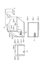
- FIG. 3A is a perspective view
- FIG. 3B is a top view
- FIG. 3C is a front view.
- Projection ranges in which the projection light L1 can be projected by the light projection unit 1 are 12a-1, 12b-1, and 12b-6.
- the detectable range of the shadow area 13 by the shadow area detection unit 2 is 12a-2, 12a-3, 12b-2, and 12b-4 in addition to 12a-1 and 12b-1. Therefore, 12a-1 and 12b-1 in the thick frames shown in FIGS. 3B and 3C are the projection ranges in which the projection light L1 can be projected by the light projection unit 1, and the shadows by the shadow region detection unit 2. This is a range that overlaps the detectable range of the region 13.
- this overlapping range is the smaller of the range in which the projection light L1 reaches and the detectable range of the shadow area 13, and it is a part of the larger one.
- the shadow area correction unit 31 calculates a correspondence relationship between each pixel of the image acquired by the shadow area detection unit 2 and the projection light L1 of the light projection unit 1 in advance, and creates and stores a correspondence map. .
- the shadow region correction unit 31 actually acquires an image obtained by capturing the shadow region 13 by the shadow region detection unit 2, the shadow region correction unit 31 refers to the correspondence map and specifies the light of the projection light L1 corresponding to the shadow region 13. .
- the projection range setting means 32 sets the shadow correction area corrected by the shadow area correction means 31 as the light projection range, and sets the other areas as the non-light projection range.
- the projection range setting means 32 may set the region corresponding to the shadow region 13 as the first projection range and the other as the second projection range.
- the projection range setting means 32 can set the projection light L1 individually for the first projection range and the second projection range, respectively. Thereby, different projection light L1 can be projected to the area
- Projection light setting means 33 sets the light to be projected onto the light projection range set by the projection range setting means 32. Specifically, the projection light setting unit 33 sets the light to be projected onto the projection range set by the projection range setting unit 32 or the first projection range and the second projection range. For example, illumination light and video light to be projected individually are set. Further, the projection light setting unit 33 may have a function of specifying elements including the illuminance, luminance, luminous intensity, luminous flux, color temperature, and color rendering properties of the projection light L1 in addition to setting the projection range. Thereby, the optical projection apparatus can set the projection light L1 with the parameter for illumination use.
- the projection range setting means 32 may set black light in the first projection range. Thereby, it becomes possible not to project light on the irradiated object 11.
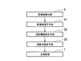
- Such an optical projection apparatus operates as shown in FIG. 4, for example.
- step S1 the light projection apparatus projects the projection light L1 on the entire projectable range including the irradiated object 11, the floor surface 12a, and the back surface 12b by the light projection unit 1.
- the shadow region detection unit 2 detects the shadow region 13 generated on the floor 12a and the back surface 12b in a state where the projection light L1 is projected by the light projection unit 1.
- the shadow area correction unit 31 refers to the image data detected by the shadow area detector 2, and determines whether or not there is an image area corresponding to the shadow area 13. Thereby, the shadow area correction unit 31 determines whether or not the shadow area 13 is detected. If the shadow area 13 is detected, the process proceeds to step S4. If the shadow area 13 is not detected, the process returns to step S1. When the process is returned to step S1, the projection light L1 is projected from the light projection unit 1, and steps S1 to S3 are repeated until the shadow is extracted by the shadow area correction unit 31.
- step S4 the shadow area correction unit 31 specifies the projection light L1 of the light projection unit 1 corresponding to the detected shadow area 13.
- projection conversion is performed so that the optical axis of the light projection unit 1 and the optical axis of the shadow region detection unit 2 on the floor surface 12a and the back surface 12b are aligned, and the projection locations on the floor surface 12a and the back surface 12b. And the detected part of the shadow area 13 are matched.
- the shadow area correction unit 31 performs the projection conversion calculation as described above, or performs the projection conversion using a correspondence map prepared in advance, whereby the projection light L1 for the shadow area 13 is obtained. To identify.
- step S5 when only the irradiated object 11 is irradiated with the projection light L1, the projection range setting unit 32 sets the correction region of the shadow region 13 corrected by the shadow region correction unit 31 as the light projection range, and otherwise. Is set to the non-light projection range.
- the projection range setting unit 32 sets the area corresponding to the shadow area 13 as the first projection range and the other area as the second projection range. The projection range.
- step S6 the projection light setting unit 33 sets the projection light L1 to be projected onto the light projection range set by the projection range setting unit 32.
- the projection light setting unit 33 sets the projection of the illumination light.
- the projection light setting unit 33 sets illumination light and video light that are individually projected.
- the projection light setting means 33 can set the black light in the first projection range and set the illumination light or video in the second projection range, so that the light is not projected onto the irradiated object 11.
- the projection light setting unit 33 sets an image to be projected as the projection light L1.
- the shadow region 13 of the irradiated object 11 is detected, and the projection region and the shadow region 13 of the light projection unit 1 are the floor surface 12a and the back surface. 12b is corrected so as to coincide with each other, and the corrected shadow area 13 is set as a light projection range.
- the light projection part 1 can project the projection light L1 in the range where the to-be-irradiated object 11 exists by projecting the projection light L1 in the set light projection range. Therefore, according to this light projection device, it is possible to irradiate only the irradiated object 11 with the projection light L1.
- this light projection apparatus does not need to measure the shape of the irradiated object 11 in advance, and can irradiate the irradiated light 11 with the projection light L1 without excess or deficiency.
- this light projection device it is possible to specify an element including any of the illuminance, luminance, luminous intensity, luminous flux, color temperature, and color rendering properties of the projection light L1, so that the projection light projected onto the irradiated object 11 L1 can be adjusted.
- the shadow region 13 as a range irradiated on the irradiated object 11 is set as the first projection range, and the other regions such as the floor surface 12a and the back surface 12b are set as the second projection range.
- the projection light L1 to be projected onto the first projection range and the second projection range can be individually set, and different projection light L1 can be projected on each.
- the light projection unit 1 when projecting the projection light L1 from the light projection unit 1, the light projection unit 1 may project the projection light L1 as illumination light.
- the light projection device can adjust the generation timing of the illumination data by the illumination data generation unit that generates the illumination data for projecting the projection light L1 as the illumination light by the light projection unit 1 under the control of the control unit 3 It is desirable that Moreover, it is desirable that the control unit 3 can adjust the irradiation timing of the illumination light by the light projection unit 1.
- the control part 3 can give a processing load to a shadow area correction process, a projection range setting process, and a projection light setting process. Moreover, the power consumption of the control part 3 can be suppressed by stopping the generation process of the illumination data by the control part 3.
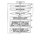
- the light projection apparatus as the second embodiment is capable of projecting the projection light L1 onto the irradiated object 11 even when the irradiated object 11 is deformed or moved.
- This light projection apparatus performs a shadow detection operation by the shadow region detection unit 2, a shadow region correction operation by the shadow region correction unit 31, and a projection range setting operation by the projection range setting unit 32 at arbitrary time intervals. Thereby, even if the position and shape of the irradiated object 11 change, the projection range of the projected light L1 is automatically updated, and separate projected light L1 is applied to the irradiated object 11 and the other floor surface 12a and back surface 12b. The operation of projecting can be maintained.
- the shadow area detection unit 2 detects the deformation or movement of the shadow area 13, and the shadow area correcting unit 31 recognizes the deformation or movement.
- the light projection unit 1 irradiates the projection possible range of the light projection unit 1 with the projection light L1.
- the shadow area detection unit 2 can detect the shadow area 13 as a result of the deformation or movement of the irradiated object 11, and can project the projection light L ⁇ b> 1 on the irradiated object 11 corresponding to the shadow area 13.
- the irradiation of the projection light L1 by the light projection unit 1 for detecting the deformation or movement of the shadow region 13 is preferably performed over the entire projectable range at a constant interval for only a very short time.
- This operation can be easily implemented in the above-described optical projection apparatus, and is effective in detecting the shadow region 13 reliably and accurately.
- luminance flickering occurs.
- the shadow area correction unit 31 detects a deformation or movement of the shadow area 13 by detecting a difference in the shape of the shadow area 13 that moves back and forth in time.
- the shadow area detection unit 2 only the deformation or movement of the shadow area 13 is detected by the shadow area detection unit 2, the shadow area 13 is corrected by the shadow area correction means 31, and the projection light L 1 is projected by the projection range setting means 32. Set the range.
- the shadow area detection unit 2 can detect the shadow area 13 as a result of deformation or movement of the irradiated object 11 and can project the projection light L1 on the irradiated object 11 corresponding to the shadow area 13.
- the projection range of the light projection unit 1 is automatically updated, and the projection is performed separately on the irradiated object 11 and other regions. Can be maintained.
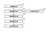
- an invisible light projection unit 41 may be used as shown in FIG.
- the invisible light projecting means 41 projects invisible light that cannot be seen by a person viewing the irradiated object 11 or the like.
- the invisible light projection means 41 is arranged so as to be in the same projection range as the visible light projection means 1 ′ corresponding to the light projection unit 1. For example, they are arranged so as to have the same projection axis as that of the visible light projection means 1 '.
- the invisible light projection means 41 for example, an infrared light source can be used. In this case, the shadow area detection unit 2 needs to use an infrared camera.
- the invisible light projection means 41 is connected to the shadow area correction means 31.
- the invisible light projection unit 41 is driven by the shadow region correction unit 31.
- invisible light is projected by the invisible light projection means 41, and the shadow region detection unit 2 can detect the shadow region 13 generated by the invisible light.
- the shadow area correction means 31 can recognize the shadow area 13 in the image data when the shadow area 13 is detected.
- the position of the invisible light projecting unit 41 in FIG. 6 is 41 ′, and the invisible light projected from the invisible light projecting unit 41 ′ is used.
- Invisible light reflecting means 42 for reflecting the light may be provided.
- the invisible light reflecting means 42 may be, for example, a mirror that transmits the projection light L1 (visible light) from the light projection unit 1 and reflects the invisible light from the invisible light projection means 41 '.
- This light projection apparatus does not block the visible light projected from the visible light projection means 1 'by the invisible light projection means 41'. Therefore, visible light is projected onto the entire projectable range by the visible light projection unit 1 ′, and invisible light is projected onto the projectable range of the visible light projection unit 1 ′ via the invisible light reflection unit 42 by the invisible light projection unit 41 ′. Can be projected.
- this light projection device even when the irradiated object 11 is deformed or moved, the change of the shadow region 13 due to the deformation or movement is detected, and the projection range of the projection light L1 is determined. Can be updated. Therefore, according to this light projection device, it is possible to follow the deformation or movement of the irradiated object 11.
- the light projection apparatus as the third embodiment includes two or more light projection units 1a and 1b.
- the light projector is configured to project the projection light from two or more positions.
- the projection range setting unit 32 sets a plurality of projection ranges corresponding to the light projection units 1a and 1b. In this embodiment, there are two light projection units 1a and 1b, but the number may be more than two.
- This light projection apparatus can widen the entire projection range by, for example, the projection ranges of the light projection units 1a and 1b. Thereby, even when the light projection unit 1 with a narrow projection range is used or when the required projection range is wide, the projection light L1 can be projected onto a range that cannot be projected with one light projection unit 1.
- the light projection units 1a and 1b are arranged so as to project the irradiated object 11 from different angles.
- the light projection apparatus can project the projection light L1 onto the irradiated object 11, the floor surface 12a, and the back surface 12b from multiple directions by the light projection units 1a and 1b.
- the light projection units 1a and 1b may be arranged so that the projection ranges of the light projection units 1a and 1b overlap. Thereby, the brightness
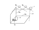
- the light projection apparatus as the fourth embodiment includes two or more shadow area detection units 2a and 2b. Thereby, the light projection device is configured to detect the shadow region 13 from two or more positions.
- the shadow area correction unit 31 calculates the correction area of the shadow area 13 corresponding to each of the shadow area detection units 2a and 2b, and the projection range setting unit 32 sets the projection range.
- the projection range setting means 32 sets the projection range of the light projection unit 1 by integrating the correction regions of the shadow regions 13. In this embodiment, there are two light projection units 1a and 1b, but the number may be more than two.
- the shadow area correction means 31 calculates a correction area of the shadow area 13 corresponding to each shadow area detection position.
- the projection range setting unit 32 sets the projection range of the light projection unit 1 by integrating the corrected shadow regions 13.
- the shadow area 13 is detected from two or more positions, so that the detection range of the shadow area 13 can be expanded. Further, according to this light projection apparatus, the shadow area 13 on the floor surface 12a and the back surface 12b of the irradiated object 11 can be detected from multiple directions, so that the blind spot of the shadow area 13 viewed from the shadow area detection units 2a and 2b can be suppressed. The detection accuracy of the shadow area 13 can be improved. This is because, depending on the positional relationship between the irradiated object 11 and the shadow area detectors 2a and 2b, there are portions (dead spots) where the shadow area detectors 2a and 2b cannot observe the floor 12a and the back surface 12b of the irradiated object 11. Resulting in. On the other hand, by detecting the shadow region 13 from two or more positions, the shadow region 13 on the floor 12a and the back surface 12b can be measured from many directions, and the blind spot can be eliminated.
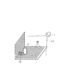
- the shadow area detection unit 2 is an optical sensor 50 embedded in the floor surface 12 a and the back surface 12 b of the irradiated object 11. That is, in the above-described embodiment, the shadow region detection unit 2 has been described as a camera or the like, but a large number of optical sensors 50 are provided instead.
- Each optical sensor 50 supplies the light intensity signal detected by itself to the shadow area correction means 31.
- the shadow area correction unit 31 specifies the shadow area 13 of the floor 12a and the back 12b from the light intensity signal and position information of each optical sensor 50.
- the shadow area correction unit 31 may detect a change in luminance of the floor 12a and the back 12b, which is a change in the light intensity signal, or may detect a change in color. Thereby, the shadow area correction unit 31 can detect the tracking area 13 following the object 11 even if the irradiated object 11 is deformed or moved.
- the shadow area correction unit 31 corrects the shadow area 13 so that the projection area of the light projection unit 1 and the shadow area 13 coincide on the floor surface 12a and the back surface 12b.
- the shadow area correction unit 31 creates a correspondence map between each of the optical sensors 50 and the projection range of the light projection unit 1 in advance, and refers to the correspondence map so as to correspond to the shadow region 13.
- the projection light L1 from 1 may be determined.
- the projection range setting unit 32 sets the shadow region 13 corrected by the shadow region correction unit 31 as the projection range of the light projection unit 1.
- the shadow region 13 is specified not by image data but by the detection result of the optical sensor 50, so that the detection accuracy of the shadow region 13 can be improved.
- the light projection apparatus can set the projection range of the light projection unit 1 with high accuracy for the irradiated object 11. Further, according to this light projection device, the shadow region 13 can be detected without a blind spot without using a plurality of cameras as the shadow region detection unit 2.
- the light projection device can be used for the purpose of projecting projection light onto an irradiated object arranged in an arbitrary space.
Landscapes
- Engineering & Computer Science (AREA)
- Physics & Mathematics (AREA)
- Multimedia (AREA)
- Signal Processing (AREA)
- General Physics & Mathematics (AREA)
- Spectroscopy & Molecular Physics (AREA)
- General Engineering & Computer Science (AREA)
- Optics & Photonics (AREA)
- Projection Apparatus (AREA)
- Non-Portable Lighting Devices Or Systems Thereof (AREA)
- Transforming Electric Information Into Light Information (AREA)
Abstract
L'invention concerne un dispositif de projection de lumière pouvant projeter une lumière uniquement sur un objet, qui comprend : un projecteur de lumière (1) comprenant un objet (11) en tant que plage projetable et la surface derrière cet objet (11) ; un détecteur de région d'ombre (2) qui détecte l'ombre causée par la lumière de projection (L1) qui apparait sur la surface derrière l'objet (11) ; et une unité de commande (3) qui corrige la région d'ombre (13) de telle sorte que la région de projection du projecteur de lumière (1) et la région d'ombre (13) coïncident sur la surface derrière l'objet (11), ce qui fait que la région d'ombre corrigée (13) devient la plage de projection de lumière, et permet de déterminer des régions autres que la région d'ombre (13) en tant que plage sans projection de lumière et de déterminer la lumière de projection (L1) projetée sur la plage de projection de lumière déterminée. Le projecteur de lumière (1), grâce à la projection de la lumière de projection déterminée sur la plage de projection de lumière déterminée, projette la lumière de projection (L1) sur la plage dans laquelle l'objet (11) se trouve.
Priority Applications (3)
| Application Number | Priority Date | Filing Date | Title |
|---|---|---|---|
| EP12788927.7A EP2693103A4 (fr) | 2011-05-23 | 2012-04-20 | Dispositif de projection de lumière |
| CN201280020880.8A CN103502721B (zh) | 2011-05-23 | 2012-04-20 | 光投影装置 |
| US14/113,695 US9217865B2 (en) | 2011-05-23 | 2012-04-20 | Light projection device |
Applications Claiming Priority (2)
| Application Number | Priority Date | Filing Date | Title |
|---|---|---|---|
| JP2011114709A JP5643153B2 (ja) | 2011-05-23 | 2011-05-23 | 光投影装置 |
| JP2011-114709 | 2011-05-23 |
Publications (1)
| Publication Number | Publication Date |
|---|---|
| WO2012160913A1 true WO2012160913A1 (fr) | 2012-11-29 |
Family
ID=47216997
Family Applications (1)
| Application Number | Title | Priority Date | Filing Date |
|---|---|---|---|
| PCT/JP2012/060696 WO2012160913A1 (fr) | 2011-05-23 | 2012-04-20 | Dispositif de projection de lumière |
Country Status (5)
| Country | Link |
|---|---|
| US (1) | US9217865B2 (fr) |
| EP (1) | EP2693103A4 (fr) |
| JP (1) | JP5643153B2 (fr) |
| CN (1) | CN103502721B (fr) |
| WO (1) | WO2012160913A1 (fr) |
Cited By (1)
| Publication number | Priority date | Publication date | Assignee | Title |
|---|---|---|---|---|
| WO2019207189A1 (fr) * | 2018-04-25 | 2019-10-31 | Defensya Ingeniería Internacional, S.L. | Système et procédé pour créer, moduler et détecter des ombres dans des systèmes de commande basé sur un système de visualisation à distance |
Families Citing this family (9)
| Publication number | Priority date | Publication date | Assignee | Title |
|---|---|---|---|---|
| US20130310652A1 (en) * | 2012-05-15 | 2013-11-21 | The Cleveland Clinic Foundation | Integrated surgical task lighting |
| JP2015043556A (ja) * | 2013-07-24 | 2015-03-05 | 株式会社リコー | 情報処理装置、画像投影システム、及びプログラム |
| JP2015139177A (ja) * | 2014-01-24 | 2015-07-30 | 株式会社東芝 | 制御装置、制御方法、および画像投影システム |
| US9746370B2 (en) | 2014-02-26 | 2017-08-29 | Sensity Systems Inc. | Method and apparatus for measuring illumination characteristics of a luminaire |
| JP6410079B2 (ja) | 2014-06-26 | 2018-10-24 | パナソニックIpマネジメント株式会社 | 光投影装置及びそれを用いた照明装置 |
| US20160071486A1 (en) * | 2014-09-09 | 2016-03-10 | Cisco Technology, Inc. | Immersive projection lighting environment |
| US20170102288A1 (en) * | 2015-10-13 | 2017-04-13 | Fluke Corporation | Three-dimensional inspection of optical communication links |
| CN107087148A (zh) * | 2017-06-30 | 2017-08-22 | 合肥久能图文科技有限公司 | 一种投影仪投影监测自调节系统 |
| TR201909524A2 (tr) * | 2019-06-26 | 2020-11-23 | Atatuerk Ueniversitesi Rektoerluegue Bilimsel Arastirma Projeleri Bap Koordinasyon Birimi | Akilli, uyarlanabi̇li̇r dalga boylu aydinlatma si̇stemi̇ |
Citations (4)
| Publication number | Priority date | Publication date | Assignee | Title |
|---|---|---|---|---|
| JP2008135345A (ja) * | 2006-11-29 | 2008-06-12 | Toshiba Lighting & Technology Corp | 照明器具及び照明システム |
| JP2009117351A (ja) | 2007-10-17 | 2009-05-28 | Panasonic Electric Works Co Ltd | 照明装置 |
| JP2009225432A (ja) | 2008-02-22 | 2009-10-01 | Panasonic Electric Works Co Ltd | 光投影装置、照明装置 |
| JP2010015996A (ja) * | 2007-07-26 | 2010-01-21 | Panasonic Electric Works Co Ltd | 照明装置 |
Family Cites Families (9)
| Publication number | Priority date | Publication date | Assignee | Title |
|---|---|---|---|---|
| US6361173B1 (en) * | 2001-02-16 | 2002-03-26 | Imatte, Inc. | Method and apparatus for inhibiting projection of selected areas of a projected image |
| US6984039B2 (en) * | 2003-12-01 | 2006-01-10 | Eastman Kodak Company | Laser projector having silhouette blanking for objects in the output light path |
| US20060244921A1 (en) * | 2005-04-28 | 2006-11-02 | Childers Winthrop D | Contrast enhancement by selectively using light attenuating modulator |
| US7984995B2 (en) * | 2006-05-24 | 2011-07-26 | Smart Technologies Ulc | Method and apparatus for inhibiting a subject's eyes from being exposed to projected light |
| US7612805B2 (en) * | 2006-07-11 | 2009-11-03 | Neal Solomon | Digital imaging system and methods for selective image filtration |
| JP4270264B2 (ja) * | 2006-11-01 | 2009-05-27 | セイコーエプソン株式会社 | 画像補正装置、プロジェクションシステム、画像補正方法、画像補正プログラム、および記録媒体 |
| TWI325998B (en) * | 2006-12-20 | 2010-06-11 | Delta Electronics Inc | Projection apparatus and system |
| US8681224B2 (en) * | 2007-06-26 | 2014-03-25 | Dublin City University | Method for high precision lens distortion calibration and removal |
| US8290208B2 (en) | 2009-01-12 | 2012-10-16 | Eastman Kodak Company | Enhanced safety during laser projection |
-
2011
- 2011-05-23 JP JP2011114709A patent/JP5643153B2/ja active Active
-
2012
- 2012-04-20 US US14/113,695 patent/US9217865B2/en not_active Expired - Fee Related
- 2012-04-20 EP EP12788927.7A patent/EP2693103A4/fr not_active Withdrawn
- 2012-04-20 WO PCT/JP2012/060696 patent/WO2012160913A1/fr active Application Filing
- 2012-04-20 CN CN201280020880.8A patent/CN103502721B/zh not_active Expired - Fee Related
Patent Citations (4)
| Publication number | Priority date | Publication date | Assignee | Title |
|---|---|---|---|---|
| JP2008135345A (ja) * | 2006-11-29 | 2008-06-12 | Toshiba Lighting & Technology Corp | 照明器具及び照明システム |
| JP2010015996A (ja) * | 2007-07-26 | 2010-01-21 | Panasonic Electric Works Co Ltd | 照明装置 |
| JP2009117351A (ja) | 2007-10-17 | 2009-05-28 | Panasonic Electric Works Co Ltd | 照明装置 |
| JP2009225432A (ja) | 2008-02-22 | 2009-10-01 | Panasonic Electric Works Co Ltd | 光投影装置、照明装置 |
Non-Patent Citations (1)
| Title |
|---|
| See also references of EP2693103A4 |
Cited By (1)
| Publication number | Priority date | Publication date | Assignee | Title |
|---|---|---|---|---|
| WO2019207189A1 (fr) * | 2018-04-25 | 2019-10-31 | Defensya Ingeniería Internacional, S.L. | Système et procédé pour créer, moduler et détecter des ombres dans des systèmes de commande basé sur un système de visualisation à distance |
Also Published As
| Publication number | Publication date |
|---|---|
| US9217865B2 (en) | 2015-12-22 |
| CN103502721A (zh) | 2014-01-08 |
| JP5643153B2 (ja) | 2014-12-17 |
| CN103502721B (zh) | 2015-06-24 |
| US20140043545A1 (en) | 2014-02-13 |
| EP2693103A4 (fr) | 2015-08-19 |
| JP2012243665A (ja) | 2012-12-10 |
| EP2693103A1 (fr) | 2014-02-05 |
Similar Documents
| Publication | Publication Date | Title |
|---|---|---|
| JP5643153B2 (ja) | 光投影装置 | |
| US9613433B2 (en) | Method of characterizing a light source and a mobile device | |
| US9560345B2 (en) | Camera calibration | |
| JP6111706B2 (ja) | 位置検出装置、調整方法、および調整プログラム | |
| JP7090446B2 (ja) | 画像処理装置 | |
| US10595014B2 (en) | Object distance determination from image | |
| US10007337B2 (en) | Eye gaze imaging | |
| JP7270702B2 (ja) | 深度感知システムおよび方法 | |
| JP2004102009A5 (fr) | ||
| WO2019107060A1 (fr) | Système de commande d'éclairage et procédé de commande d'éclairage | |
| US20230102878A1 (en) | Projector and projection method | |
| WO2017061213A1 (fr) | Dispositif d'affichage par projection, et procédé de correction d'image | |
| US20180300017A1 (en) | Display device and method of controlling display device | |
| US20150248174A1 (en) | Position detecting device and position detecting method | |
| US9654748B2 (en) | Projection device, and projection method | |
| JP2010078854A (ja) | 照明装置 | |
| JP6182739B2 (ja) | 投影装置及び投影方法 | |
| JP2018537884A (ja) | モバイル機器によって画像を撮影する方法 | |
| JP2020076675A5 (fr) | ||
| JP2005159426A (ja) | 自動台形歪補正手段を備えたプロジェクタ | |
| KR20130046885A (ko) | 영상 촬영 장치 | |
| TW201325308A (zh) | 照明控制系統以及照明控制方法 | |
| US20230412782A1 (en) | Display method and display system | |
| US11755152B2 (en) | Projector with detection function for stabilizing intensity distribution of an irradiation beam | |
| KR20150063857A (ko) | 곡면 디스플레이 장치 |
Legal Events
| Date | Code | Title | Description |
|---|---|---|---|
| 121 | Ep: the epo has been informed by wipo that ep was designated in this application |
Ref document number: 12788927 Country of ref document: EP Kind code of ref document: A1 |
|
| WWE | Wipo information: entry into national phase |
Ref document number: 14113695 Country of ref document: US |
|
| WWE | Wipo information: entry into national phase |
Ref document number: 2012788927 Country of ref document: EP |
|
| NENP | Non-entry into the national phase |
Ref country code: DE |