WO2012160893A1 - 肌サンプリング部材、測定装置および測定方法 - Google Patents
肌サンプリング部材、測定装置および測定方法 Download PDFInfo
- Publication number
- WO2012160893A1 WO2012160893A1 PCT/JP2012/059803 JP2012059803W WO2012160893A1 WO 2012160893 A1 WO2012160893 A1 WO 2012160893A1 JP 2012059803 W JP2012059803 W JP 2012059803W WO 2012160893 A1 WO2012160893 A1 WO 2012160893A1
- Authority
- WO
- WIPO (PCT)
- Prior art keywords
- skin
- light
- fluorescence
- housing
- layer
- Prior art date
- Legal status (The legal status is an assumption and is not a legal conclusion. Google has not performed a legal analysis and makes no representation as to the accuracy of the status listed.)
- Ceased
Links
Images





Classifications
-
- A—HUMAN NECESSITIES
- A61—MEDICAL OR VETERINARY SCIENCE; HYGIENE
- A61B—DIAGNOSIS; SURGERY; IDENTIFICATION
- A61B5/00—Measuring for diagnostic purposes; Identification of persons
- A61B5/68—Arrangements of detecting, measuring or recording means, e.g. sensors, in relation to patient
- A61B5/6801—Arrangements of detecting, measuring or recording means, e.g. sensors, in relation to patient specially adapted to be attached to or worn on the body surface
- A61B5/683—Means for maintaining contact with the body
- A61B5/6834—Means for maintaining contact with the body using vacuum
-
- G—PHYSICS
- G01—MEASURING; TESTING
- G01N—INVESTIGATING OR ANALYSING MATERIALS BY DETERMINING THEIR CHEMICAL OR PHYSICAL PROPERTIES
- G01N21/00—Investigating or analysing materials by the use of optical means, i.e. using sub-millimetre waves, infrared, visible or ultraviolet light
- G01N21/01—Arrangements or apparatus for facilitating the optical investigation
-
- A—HUMAN NECESSITIES
- A61—MEDICAL OR VETERINARY SCIENCE; HYGIENE
- A61B—DIAGNOSIS; SURGERY; IDENTIFICATION
- A61B5/00—Measuring for diagnostic purposes; Identification of persons
- A61B5/0059—Measuring for diagnostic purposes; Identification of persons using light, e.g. diagnosis by transillumination, diascopy, fluorescence
- A61B5/0071—Measuring for diagnostic purposes; Identification of persons using light, e.g. diagnosis by transillumination, diascopy, fluorescence by measuring fluorescence emission
-
- A—HUMAN NECESSITIES
- A61—MEDICAL OR VETERINARY SCIENCE; HYGIENE
- A61B—DIAGNOSIS; SURGERY; IDENTIFICATION
- A61B5/00—Measuring for diagnostic purposes; Identification of persons
- A61B5/145—Measuring characteristics of blood in vivo, e.g. gas concentration or pH-value ; Measuring characteristics of body fluids or tissues, e.g. interstitial fluid or cerebral tissue
- A61B5/14532—Measuring characteristics of blood in vivo, e.g. gas concentration or pH-value ; Measuring characteristics of body fluids or tissues, e.g. interstitial fluid or cerebral tissue for measuring glucose, e.g. by tissue impedance measurement
-
- A—HUMAN NECESSITIES
- A61—MEDICAL OR VETERINARY SCIENCE; HYGIENE
- A61B—DIAGNOSIS; SURGERY; IDENTIFICATION
- A61B5/00—Measuring for diagnostic purposes; Identification of persons
- A61B5/145—Measuring characteristics of blood in vivo, e.g. gas concentration or pH-value ; Measuring characteristics of body fluids or tissues, e.g. interstitial fluid or cerebral tissue
- A61B5/1455—Measuring characteristics of blood in vivo, e.g. gas concentration or pH-value ; Measuring characteristics of body fluids or tissues, e.g. interstitial fluid or cerebral tissue using optical sensors, e.g. spectral photometrical oximeters
-
- A—HUMAN NECESSITIES
- A61—MEDICAL OR VETERINARY SCIENCE; HYGIENE
- A61B—DIAGNOSIS; SURGERY; IDENTIFICATION
- A61B5/00—Measuring for diagnostic purposes; Identification of persons
- A61B5/44—Detecting, measuring or recording for evaluating the integumentary system, e.g. skin, hair or nails
- A61B5/441—Skin evaluation, e.g. for skin disorder diagnosis
-
- A—HUMAN NECESSITIES
- A61—MEDICAL OR VETERINARY SCIENCE; HYGIENE
- A61B—DIAGNOSIS; SURGERY; IDENTIFICATION
- A61B5/00—Measuring for diagnostic purposes; Identification of persons
- A61B5/44—Detecting, measuring or recording for evaluating the integumentary system, e.g. skin, hair or nails
- A61B5/441—Skin evaluation, e.g. for skin disorder diagnosis
- A61B5/443—Evaluating skin constituents, e.g. elastin, melanin, water
-
- A—HUMAN NECESSITIES
- A61—MEDICAL OR VETERINARY SCIENCE; HYGIENE
- A61B—DIAGNOSIS; SURGERY; IDENTIFICATION
- A61B5/00—Measuring for diagnostic purposes; Identification of persons
- A61B5/68—Arrangements of detecting, measuring or recording means, e.g. sensors, in relation to patient
- A61B5/6801—Arrangements of detecting, measuring or recording means, e.g. sensors, in relation to patient specially adapted to be attached to or worn on the body surface
- A61B5/6843—Monitoring or controlling sensor contact pressure
-
- G—PHYSICS
- G01—MEASURING; TESTING
- G01N—INVESTIGATING OR ANALYSING MATERIALS BY DETERMINING THEIR CHEMICAL OR PHYSICAL PROPERTIES
- G01N21/00—Investigating or analysing materials by the use of optical means, i.e. using sub-millimetre waves, infrared, visible or ultraviolet light
- G01N21/17—Systems in which incident light is modified in accordance with the properties of the material investigated
- G01N21/25—Colour; Spectral properties, i.e. comparison of effect of material on the light at two or more different wavelengths or wavelength bands
- G01N21/31—Investigating relative effect of material at wavelengths characteristic of specific elements or molecules, e.g. atomic absorption spectrometry
- G01N21/35—Investigating relative effect of material at wavelengths characteristic of specific elements or molecules, e.g. atomic absorption spectrometry using infrared light
- G01N21/359—Investigating relative effect of material at wavelengths characteristic of specific elements or molecules, e.g. atomic absorption spectrometry using infrared light using near infrared light
-
- G—PHYSICS
- G01—MEASURING; TESTING
- G01N—INVESTIGATING OR ANALYSING MATERIALS BY DETERMINING THEIR CHEMICAL OR PHYSICAL PROPERTIES
- G01N21/00—Investigating or analysing materials by the use of optical means, i.e. using sub-millimetre waves, infrared, visible or ultraviolet light
- G01N21/62—Systems in which the material investigated is excited whereby it emits light or causes a change in wavelength of the incident light
- G01N21/63—Systems in which the material investigated is excited whereby it emits light or causes a change in wavelength of the incident light optically excited
- G01N21/64—Fluorescence; Phosphorescence
-
- A—HUMAN NECESSITIES
- A61—MEDICAL OR VETERINARY SCIENCE; HYGIENE
- A61B—DIAGNOSIS; SURGERY; IDENTIFICATION
- A61B5/00—Measuring for diagnostic purposes; Identification of persons
- A61B5/103—Measuring devices for testing the shape, pattern, colour, size or movement of the body or parts thereof, for diagnostic purposes
-
- G—PHYSICS
- G01—MEASURING; TESTING
- G01N—INVESTIGATING OR ANALYSING MATERIALS BY DETERMINING THEIR CHEMICAL OR PHYSICAL PROPERTIES
- G01N21/00—Investigating or analysing materials by the use of optical means, i.e. using sub-millimetre waves, infrared, visible or ultraviolet light
- G01N21/17—Systems in which incident light is modified in accordance with the properties of the material investigated
- G01N21/25—Colour; Spectral properties, i.e. comparison of effect of material on the light at two or more different wavelengths or wavelength bands
- G01N21/31—Investigating relative effect of material at wavelengths characteristic of specific elements or molecules, e.g. atomic absorption spectrometry
- G01N21/314—Investigating relative effect of material at wavelengths characteristic of specific elements or molecules, e.g. atomic absorption spectrometry with comparison of measurements at specific and non-specific wavelengths
- G01N2021/3144—Investigating relative effect of material at wavelengths characteristic of specific elements or molecules, e.g. atomic absorption spectrometry with comparison of measurements at specific and non-specific wavelengths for oxymetry
Definitions
- the present invention relates to a skin sampling member that samples skin, a measuring device including the skin sampling member, and a measuring method using the skin sampling member.
- anti-glycation (anti-aging) cosmetics have been commercialized for the purpose of reducing AGEs (Advanced Glycation End Products) accumulated in the skin.
- AGEs are final products formed by a non-enzymatic sugar addition reaction (Maillard reaction) between proteins and carbohydrates or lipids, exhibiting a yellowish brown color, and some of them are fluorescent substances.
- AGEs have a property of forming a crosslink by binding to a nearby structural protein.
- the cross-linking of AGEs with collagen constituting the dermis has a problem of reducing skin elasticity and causing dullness.
- Known methods for measuring the skin condition include methods for measuring the amount of water and oil in the sebum layer and stratum corneum of the skin, and methods for measuring the surface potential. There is a problem that it is only.
- Patent Document 1 As another method for measuring the skin condition, there is a skin discrimination method disclosed in Patent Document 1.
- the stratum corneum cells collected from the skin are irradiated with ultraviolet rays by a tape stripping method in which the horny cells are sampled using an adhesive tape, and the ⁇ -sheet type of the horny layer cells is determined by the intensity of fluorescence emitted by the ultraviolet rays.
- Patent Document 2 As another method for measuring the skin condition, there is a technique disclosed in Patent Document 2 or 3. In the techniques described in these documents, reflected light of light irradiated on the skin is detected.
- Japanese Patent Publication Japanese Patent Laid-Open No. 2005-348991 (published on December 22, 2005)” Japanese Patent Publication “Japanese Patent Laid-Open No. 2004-290234 (published on October 21, 2004)” International publication pamphlet “WO 01/28869 A1 (April 5, 2001 international publication)”
- the discrimination method described in Patent Document 1 has a problem that only skin knowledge obtained from keratinocytes can be obtained.
- the discrimination method there is a problem that the procedure from collecting the keratinocytes to measuring the fluorescence from the keratinocytes is complicated.
- the discrimination method described in Patent Document 1 is (1) A step of collecting keratinocytes from the skin using an adhesive tape, (2) A process of dissolving the adhesive tape with an organic solvent over half a day, (3) a step of preparing a preparation with the obtained corneocytes, and (4) At least four steps of measuring the fluorescence of the preparation using a fluorescence spectrophotometer are included. For this reason, there exists a problem that the procedure until a test subject confirms the state of his skin is very complicated.
- Patent Documents 2 and 3 since the techniques described in Patent Documents 2 and 3 detect the reflected light of the skin, the procedure is simple, but both detect the skin condition including the epidermis layer or dermis layer deep in the skin. There is a problem that it is difficult.
- the present invention has been made to solve the above-mentioned problems, and skin sampling that enables easy sampling of a part of the skin for the purpose of confirming the state of the skin including at least the epidermis layer or the dermis layer.
- An object is to provide a member, a measuring device including the skin sampling member, and a measuring method using the skin sampling member.
- the skin sampling member of the present invention includes a housing made of a light-transmitting material, a suction hole provided in the housing for sucking skin, and the housing. And an exhaust hole for decompressing the inside of the housing.
- the suction hole is brought into contact with a specific part (measurement target part) of the living body, and the inside of the housing is decompressed through the exhaust hole, whereby a part of the skin is housing through the suction hole. Can be sucked inside. Therefore, the specific site
- Measured portion can be exemplified by subject's arm, wrist, earlobe, fingertip, palm, cheek, inner side of second arm, and the like.
- the casing since the casing has translucency, light is irradiated to a part of the skin by irradiating light to a part of the skin (a specific part of the skin) sucked into the casing. It becomes possible to optically measure the light generated by this.
- the skin sampling member of the present invention is provided in the casing made of a light-transmitting material, the suction hole provided in the casing, for sucking skin, and provided in the casing. And an exhaust hole for decompressing the inside of the housing.
- FIG. 1 It is a figure which shows the whole structure of the measuring apparatus which is one embodiment of this invention. It is a figure which shows the external appearance of the suction mechanism (skin sampling member) which is one embodiment of this invention, (a) is a perspective view which shows the external appearance of the said suction mechanism (skin sampling member), (b) It is a side view which shows the external appearance of the said suction mechanism. It is a figure which shows typically that the volume inside the said suction mechanism is variable. It is a figure which shows one Example (portable type) of the said measuring apparatus. It is a figure which shows the other Example (ear sensor type) of the said measuring apparatus.
- FIGS. 1 to 10 An embodiment of the present invention will be described with reference to FIGS. 1 to 10 as follows. Descriptions of configurations other than those described in the following specific items may be omitted as necessary. However, in the case where they are described in other items, the configurations are the same. For convenience of explanation, members having the same functions as those shown in each item are given the same reference numerals, and the explanation thereof is omitted as appropriate.
- FIG. 1 is a diagram illustrating an overall configuration of the measuring apparatus 100.
- FIG. 4 is a diagram showing an embodiment of the measuring apparatus 100 (hereinafter referred to as a portable measuring apparatus).
- a measurement apparatus 100 that detects (specifies) the intensity of fluorescence obtained from a part (or measurement target part) of the skin of a subject to be measured will be described.
- the data specified by the measurement apparatus 100 is not limited to such fluorescence intensity, and other physical property information (or physical quantity) may be specified.
- Fluorescence fluorescence derived from substances contained in the skin generated by doing so can be listed.
- the measuring apparatus 100 is included in a part of the skin such as the half width, the detected light wavelength, the skin reflectance, and the skin transmittance in addition to the light intensity as in the present embodiment. Any physical property information (or physical quantity) derived from the substance to be identified may be used.
- a measuring device 100 includes a suction mechanism (skin sampling member, housing) 1, a light source 2a, a light source (another light source) 2b, detectors (light detection units) 3a and 3b, a conduit 6, and a pump. 7, a control unit 8, a recording unit 9, a signal conversion unit 10, and a display unit 11.
- FIG. 4 shows the appearance of the portable measuring device measurement.
- an example of the arrangement of the suction mechanism 1, the light source 2a, and the detectors 3a and 3b in the portable measuring apparatus is shown.
- TOP view in FIG. 4 shows an example of the arrangement of the suction mechanism 1, the light source 2a, and the detectors 3a and 3b when the portable measuring device is viewed from the top.
- the position of the suction hole 5 is different from that of the suction mechanism 1 shown in FIG. 1, and the suction hole 5 is opposed to the exhaust hole 4 (lower side in the figure). (Upper side in the figure).
- the suction hole 5 of the suction mechanism 1 may be provided at a position facing the exhaust hole 4.
- FIG. 4 shows an example of the arrangement of the suction mechanism 1, the light source 2a, the detectors 3a and 3b, and the pump 7 when the inside of the portable measuring apparatus is viewed obliquely.
- the shape of the suction mechanism 1 in the present embodiment is a substantially rectangular parallelepiped shape.
- the shape of the suction mechanism 1 is not limited to a substantially rectangular parallelepiped shape, and may be any shape as long as it can suck a part of the skin.
- various shapes such as the substantially rectangular parallelepiped shape, the substantially cubic shape, the truncated pyramid shape, the truncated cone shape, or the shape obtained by rounding the corners of these shapes can be adopted.
- the remaining one surface side (the lower side in the figure) of the substantially rectangular parallelepiped shape is opened to form a suction hole 5 for sucking the skin.
- the surface SUF1 is provided with an exhaust hole 4 for connection to the pump 7 via the conduit 6. That is, the exhaust hole 4 is a hole for exhausting gas (for example, air) from the inside of the suction mechanism 1 (depressurizing the inside of the suction mechanism 1).
- the constituent material of the suction mechanism 1 of the present embodiment is translucent quartz glass.
- a hole is formed in a part of a quartz cell container.
- the constituent material of the suction mechanism 1 is not limited to quartz glass, and may be a light-transmitting resin material or ceramic.
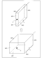
- FIG. 2A is a perspective view showing the external appearance of the suction mechanism 1.
- FIG. 2B is a side view showing the appearance of the suction mechanism 1.
- the suction mechanism 1 of the present embodiment has a length a of about 20 mm, a length b of about 25 mm, and a length c of about 10 mm (for example, FIG. 2).
- the negative pressure inside the suction mechanism 1 may be increased in order to increase the amount of skin sucked.
- the length a is 2 to 5 mm so that at least the dermis layer is included in a part of the skin sucked into the suction mechanism 1.
- both the length b and the length c must be at least 4 to 10 mm. For example, it is considered that half of the amount of skin sampled by the suction hole 5 having the length b and the length c corresponds to the thickness (depth) of the cross section of the skin to be sucked.
- the length a is at least about 2 to 5 mm
- the length b and the length c are each about twice the thickness of the dermis layer. Therefore, it needs to be at least about 4 to 10 mm.
- the inside of the suction mechanism 1 Therefore, it is necessary that the volume of at least 32 mm 3 to 500 mm 3 or more.
- the amount of skin to be sampled can be adjusted by adjusting the pressure inside the suction mechanism 1.
- the quartz cell container is configured. It is conceivable to increase or decrease the thickness of the quartz plate.
- the suction mechanism 1 may be provided with a structure in which the internal volume is variable.
- FIG. 3 schematically shows an example of the suction mechanism 1 having a variable internal volume.
- the discrimination method described in Patent Document 1 has a secondary problem that the state of the stratum corneum (or stratum corneum) can be confirmed, but the state of the epidermis layer and / or the dermis layer cannot be confirmed.
- the elasticity of the skin is not only the state of the stratum corneum which is only 0.02 mm thick as shown in FIG. 10 (a), but also the epidermis layer (thickness 0.07 to 0.2 mm), and the dermis. It depends on the state of the layer (thickness 2 mm).
- the dermis layer is composed of 70% or more of collagen fibers, but the late saccharification reaction products (AGEs) are crosslinked with the collagen fibers. By this AGE cross-linking, the three-dimensional network structure of collagen fibers is destroyed, and fibroblasts, hyaluronic acid and the like are reduced.
- crosslinking by AGEs also destroys the structure of the base layer in the boundary of an epidermis layer and a dermis layer, and the boundary between an dermis layer and an epidermis layer will also become indistinct. As a result, the elasticity of the skin is lowered, and the dullness of the skin progresses due to the color problem of AGEs.
- the suction mechanism 1 has at least a variable pressure (or volume) in the suction mechanism 1 from the first magnitude to the second magnitude described below. May be.
- the pressure (or volume) inside the suction mechanism 1 may be at least variable from the first size to the third size.
- the first size is such that most of the skin is composed of the stratum corneum.
- the second size is such that most of the skin consists of a stratum corneum and an epidermis layer.
- the third size is a size such that at least the dermis layer is included in a part of the skin.
- the pressure (or volume) inside the suction mechanism 1 when the pressure (or volume) inside the suction mechanism 1 is the first size, most of the part of the skin sucked into the suction mechanism 1 can be made up of the stratum corneum. Further, when the pressure (or volume) inside the suction mechanism 1 is the second size, most of the part of the skin sucked into the suction mechanism 1 is made up of the stratum corneum and the epidermis layer. Can do. Furthermore, when the pressure (or volume) inside the suction mechanism 1 is the third magnitude, at least a dermis layer can be included in a part of the skin sucked into the suction mechanism 1.
- the AGEs present in the stratum corneum, epidermis layer and / or dermis layer are obtained by previously associating the intensity of fluorescence to be detected with the amount of AGEs present in the stratum corneum, epidermis layer and / or dermis layer. It is also possible to specify the amount.
- the entire suction mechanism 1 may be made of a light-transmitting and elastic material (for example, silicone rubber).
- a part of the six surface portions of the suction mechanism 1 is made of an elastic material (for example, silicone rubber), and the remaining part is made of quartz glass, a hard resin material, ceramics, or the like. You may comprise.
- At least one pair of surfaces (surfaces on which light is irradiated) SUF2 and surfaces (surfaces on opposite sides) SUF3 facing each other have translucency. It is composed of a hard resin material.
- bonds between surface SUF2 and surface SUF3 is comprised with silicone rubber.
- the fluorescence from the stratum corneum, the epidermis layer and / or the dermis layer of the skin can be measured according to the amount of skin to be sampled.
- the amount of AGEs present in the horny layer, epidermis layer and / or dermis layer of the skin along the skin cross-sectional direction (depth direction from the skin surface) is measured at substantially the same location. It is also possible to do.
- the silicone raw material composition As the silicone raw material composition, commercially available products such as “KJR632” manufactured by Shin-Etsu Chemical Co., Ltd. can be used. In addition to the above components, the silicone raw material composition may contain a filler, a heat-resistant material, a plasticizer, and the like to the extent that the strength and transparency of the resulting silicone resin are not impaired.
- the silicone rubber may be a silicone rubber in which a relatively low molecular weight organopolysiloxane is crosslinked.
- the suction mechanism 1 molds the silicone raw material composition by an appropriate molding method according to the desired shape.
- it can be molded by injection molding, extrusion molding, cast molding or the like.
- the transmittance of the suction mechanism 1 is preferably 90% or more, and more preferably 92% or more.
- the transmittance of the suction mechanism 1 molded with polydimethylsiloxane is about 94%, and the transmittance of the suction mechanism 1 molded with polydiphenylsiloxane is about 92%, and the transmittance is maintained even when used for a long time.
- the suction mechanism 1 is formed of a hard silicone resin such as polydimethylsiloxane, the suction mechanism 1 is difficult to expand and is not easily deteriorated on the short wavelength side such as ultraviolet rays, and is suitable for maintaining optical characteristics.
- the suction mechanism 1 is made of silicone rubber, volatile components such as moisture and low-molecular siloxane tend to remain, so that it is preferable to volatilize them.
- the suction hole 5 is brought into contact with a specific part (measurement target part) of the living body and the inside of the suction mechanism 1 is depressurized through the exhaust hole 4. A part of the skin can be sucked into the suction mechanism 1. Therefore, the specific site
- the suction mechanism 1 since the suction mechanism 1 has translucency, light is applied to a part of the skin by irradiating light to a part of the skin sucked into the suction mechanism 1 (a specific part of the skin). It becomes possible to optically measure the light generated by the irradiation.
- the measurement result of the above optical measurement can be obtained instantaneously after irradiating light to a part of the sampled skin. For this reason, the time required for the procedure for confirming the state of the skin can be shortened compared with the discrimination method described in Patent Document 1.
- the measurement object part by the measuring apparatus 100 can illustrate the subject's arm, wrist, earlobe, fingertip, palm, cheek, inner side of the second arm, and the like.
- FIG. 6 shows a portion of the measurement target portion of the fingertip (fingertip) of the hand and a blood vessel of the wrist where the blood vessel is branched (wrist blood vessel branch position), and a portion where the blood vessel does not exist on the wrist (the wrist).
- the measurement result of the spectrum of the fluorescence by AGEs from each location of the blood vessel unconfirmed position) and palm (blood vessel unconfirmed position) is shown.
- the horizontal axis indicates the fluorescence wavelength (nm) and the vertical axis indicates the fluorescence intensity (au).
- the intensity of fluorescence per wavelength of 460 nm is 10,000 a. u.
- the portion where the blood vessel is branched (wrist blood vessel branch position)
- a remarkable fluorescence spectrum was obtained.
- the fingertip (fingertip) of the hand and the blood vessel branch (wrist) Compared with the blood vessel branch position) a large numerical value was not obtained. It can be seen that the intensity of fluorescence varies depending on the analysis location.
- AGEs are particularly likely to accumulate at the fingertip (fingertip) of the hand and the portion where the blood vessel is branched (wrist blood vessel branching position). That is, it can be seen that accurate data with higher accuracy can be obtained by determining a position where AGEs are likely to accumulate as a measurement position.
- Patent Documents 2 and 3 detect transcutaneous fluorescence as reflected light, and the apparatus is large.
- the measurement site is unspecified as to where the fluorescence information is obtained from the percutaneous region.
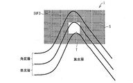
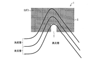
- the suction mechanism 1 may be shielded from a part of at least one surface other than the surface (light irradiation surface) SUF3 on which light is irradiated (light shielding portion S).
- a method of providing the light-shielding part S in the suction mechanism 1 a method in which a part that does not extract fluorescence is made of a light-shielding plastic or a light-shielding agent is applied to the surface of a light-transmitting material can be considered.
- emitted from the part (translucent part T) which is not shielded among some at least one surfaces other than the light irradiation surface irradiated with the light of the suction mechanism 1 is selected. Can be measured. Therefore, it becomes possible to select and measure only the fluorescence from a specific part (for example, the epidermis layer or the dermis layer) out of a part of the skin sucked into the suction mechanism 1.
- the arrangement of the light shielding portion S and the light transmitting portion T may be determined in advance according to the amount of skin sucked when the inside of the suction mechanism 1 is at a constant pressure.
- a lamp light source can be used in addition to a semiconductor element such as an LED (Light Emitting Diode) or an LD (Laser Diode).
- LED Light Emitting Diode
- LD Laser Diode
- the wavelength of light emitted from the light source 2a is suitably from 315 to 400 nm in the near ultraviolet region to 315 to 600 nm in the visible light region.
- the wavelength is 230 nm or more and 365 nm or less in the near ultraviolet region, or 405 nm in the blue-violet region.
- Fluorescence from the accumulation on the blood vessel wall at the irradiation position can be obtained by irradiating light having such a wavelength to a specific part (for example, blood vessel) of the measurement target portion.
- the wavelength of the light emitted from the light source 2a may be a wavelength within a range in which late saccharification reaction products (AGEs) can be detected.
- AGEs late saccharification reaction products
- AGEs can be detected by the above configuration.
- strength of the fluorescence derived from AGEs increases, the progress of glycation of skin can be confirmed. Therefore, it is useful to realize a measuring device that detects AGEs.
- CLF collagen-linked fluorescence
- Pentosidine and vesperlidine are typical examples of AGEs.
- Pentosidine has a structure in which pentose, equimolar lysine and arginine are cross-linked, and is a stable fluorescent substance after acid hydrolysis. In particular, it has been reported that it increases in the onset of diabetes and end-stage nephropathy.
- Vesperidin is isolated as a main fluorescent substance after acid hydrolysis of AGE-modified bovine serum albumin (BSA) and has a structure in which two molecules of lysine are cross-linked.
- BSA bovine serum albumin
- the wavelength of the excitation light is most preferably 370 nm or a wavelength in the vicinity thereof, but the excitation light width to be adapted depending on the type of AGEs is 315 to 400 nm in the ultraviolet region. From 315 to 600 nm in the visible light region is suitable.
- the light source (another light source) 2b is a near infrared light source or an infrared light source for visualizing blood vessels. Moreover, it is preferable that the light source 2b is a light source which can switch and irradiate near infrared light and infrared light.
- a light source “Multi-Wavelength LED KED694M31D” manufactured by Kyosemi Corporation can be exemplified.
- the difference in absorbance in the red or infrared region of oxyhemoglobin bound to oxygen (oxygenated hemoglobin) and deoxyhemoglobin not bound to oxygen (reduced hemoglobin) is used. It is also possible to specify the type (venous or arterial) and measure AGEs.
- FIG. 7 shows the relationship between the wavelength and absorbance of oxyhemoglobin and deoxyhemoglobin.
- the horizontal axis represents wavelength (nm), and the vertical axis represents absorbance (au).
- the absorbance of reduced hemoglobin is high on the short wavelength side
- the absorbance of oxyhemoglobin is high on the long wavelength side with 805 nm as a boundary.
- blood vessels (arteries) containing a large amount of oxyhemoglobin can be confirmed more clearly than blood vessels (veins) having a small amount of oxyhemoglobin.
- a blood vessel containing a large amount of oxidized hemoglobin that is, a blood vessel (artery) having a reduced amount of reduced hemoglobin, which has been clearly seen until then becomes unclear.
- a blood vessel containing a large amount of blood that is, a blood vessel (vein) with little oxyhemoglobin becomes clear.
- a light source that emits near-infrared light and a light source that emits infrared light may be provided separately. For example, it is possible to confirm whether or not a blood vessel is included in a part of the skin sampled in the suction mechanism 1 by switching the near infrared LED and the red LED to light.
- the near-infrared LED is a light source that emits light having a wavelength in the near-infrared region of about 945 nm (890 to 1010 nm). By irradiating the skin surface with near infrared light, oxyhemoglobin can be detected and veins can be visualized.
- the red LED is a light source that emits light having a wavelength in the red region of around 660 nm (620 to 700 nm). By irradiating the skin surface with red light, reduced hemoglobin can be detected and the artery can be visualized.
- the detectors 3a and 3b detect fluorescence generated from a part of the skin, and include a single or a plurality of light receiving elements.
- the detectors 3a and 3b may include not only a light receiving element but also a spectroscope such as a fluorescence spectrophotometer. As a result, finer detection data based on the spectroscopic fluorescence can be analyzed.
- semiconductor elements such as PD (Photo Diode), CCD (Charge Coupled Devices), and CMOS (Complementary Metal-Oxide-Semiconductor) can be exemplified.
- PD Photo Diode
- CCD Charge Coupled Devices
- CMOS Complementary Metal-Oxide-Semiconductor
- Fluorescence generated from a part of the skin has a wavelength longer than that of the excitation light, so from Table 1, any detector that can detect light in the range of 350 to 500 nm may be used. However, fluorescence can also be used as long as it can detect the range of 320 to 900 nm because the wavelength to be detected varies depending on the type of AGEs.
- the suction mechanism 1 there is no separate optical component between the suction mechanism 1 and the detectors 3a and 3b, but a single or a plurality of components are provided between the suction mechanism 1 and the detectors 3a and 3b.
- the optical component may be present.
- optical components include various optical members and light guide members such as optical fibers.
- optical members are members that change the state of fluorescence generated from a part of the skin.
- optical members include prisms, lenses, wavelength conversion elements, optical filters, diffraction gratings, polarizing plates, and optical path changing members.
- the “lens” is a member that adjusts the spot diameter of fluorescence.
- the “wavelength conversion element” is a member that converts fluorescence into light having different wavelengths.
- the “optical filter” is a member that blocks light having a wavelength in a predetermined wavelength range and transmits light having other wavelengths.
- optical path changing member is a member that changes the optical path of the laser light, and is, for example, a mirror.
- the detectors 3a and 3b are provided with the detector 3a or the detector 3b depending on the presence of the skin sucked in the suction hole 5. It can be installed at any position in the vicinity of the suction mechanism 1 except for a position where it cannot be.
- the suction hole 5 in the skin
- the suction hole 5 may be detected from the vicinity of the surface SUF4 facing the contact side).
- it may be detected from the vicinity of the surface SUF5 where the presence of the conduit 6 does not get in the way. If the presence of the conduit 6 does not get in the way, it may be detected from the vicinity of the surface SUF1.
- the surface on the side irradiated with the excitation light (the surface on the light irradiation side, the light irradiation surface) the surface on the side opposite to the SUF2 (the surface on the opposite side) SUF3 You may install in the vicinity.
- the light detected by the detector 3a is not limited to fluorescence generated from a part of the skin, but also includes transmitted light in which excitation light emitted from the light sources 2a and 2b is transmitted through a part of the skin.
- the light to be detected is not limited to fluorescence generated from a part of the skin, but also includes reflected light in which excitation light emitted from the light sources 2a and 2b is reflected from a part of the skin.
- the light detected by the detector is not limited to the fluorescence generated from a part of the skin, but the reflection of the excitation light emitted from the light sources 2a and 2b reflected by a part of the skin.
- Light is also included.
- the detector may have a coaxial fiber shape that can detect fluorescence and reflected light with a single fiber. In any case, by measuring the intensity of the fluorescence received by the detectors 3a and 3b, it is possible to measure the amount of accumulated substances (for example, AGEs) in the living body.
- any one of the detectors 3a and 3b may be an imaging device that images a measurement target portion in order to visualize a blood vessel included in a part of the skin.
- the imaging device include a CCD camera and a CMOS camera in which light receiving elements are arranged in an array (or matrix), but other imaging devices may be used.
- This imaging device is installed outside the suction mechanism 1 and images the measurement target portion.
- a commercially available digital camera may be equipped with an IR cut filter that transmits visible light and reflects infrared light in front of the image sensor.
- a band-pass filter that only passes can be inserted.
- the elasticity of the skin is not only the state of the stratum corneum which is only 0.02 mm thick as shown in FIG. 10 (a), but also the epidermis layer (thickness 0.07 to 0.2 mm), and the dermis. It depends on the state of the layer (thickness 2 mm).
- the dermis layer is composed of 70% or more of collagen fibers, but AGEs are crosslinked with the collagen fibers. By the crosslinking with AGEs, the three-dimensional network structure of collagen fibers is destroyed, and fibroblasts, hyaluronic acid and the like are reduced.
- crosslinking by AGEs also destroys the structure of the base layer in the boundary of an epidermis layer and a dermis layer, and the boundary between a dermis layer and an epidermis layer will also become indistinct. As a result, the elasticity of the skin is lowered, and the dullness of the skin progresses due to the color problem of AGEs.
- the measuring apparatus 100 may include a pump 7 that depressurizes the inside of the suction mechanism 1 via the exhaust hole 4 of the suction mechanism 1 in order to solve the secondary problem. As shown in FIG. 1, the pump 7 is connected to the exhaust hole 4 via a conduit 6.
- the pump 7 may be electric or manual, but “NMP05S” manufactured by NK Japan Co., Ltd. or “Micro Ring Pump DSA-2-12BL” manufactured by Aquatech Co., Ltd. may be used.
- the inside of the suction mechanism 1 can be decompressed using the pump 7, and a part of the skin can be sucked into the suction mechanism 1 through the suction hole 5.
- the amount of skin sucked into the suction mechanism 1 can be adjusted by adjusting the negative pressure inside the suction mechanism 1 by the pump 7.
- the suction mechanism 1 it is possible to measure fluorescence derived from AGEs present in the stratum corneum, epidermis layer and / or dermis layer. For this reason, the AGEs present in the stratum corneum, epidermis layer and / or dermis layer are obtained by previously associating the intensity of fluorescence to be detected with the amount of AGEs present in the stratum corneum, epidermis layer and / or dermis layer. It is also possible to specify the amount.
- the measuring apparatus 100 it is possible to know which part of the stratum corneum, epidermis layer and / or dermis layer is glycated, and skin sampling at the site of counseling such as confirming the effect of cosmetics.
- the member can be used.
- Patent Documents 2 and 3 detect transcutaneous fluorescence as reflected light, and the apparatus is large.
- the measurement site is unspecified as to where the fluorescence information is obtained from the percutaneous region.
- the amount of skin to be sampled can be adjusted by adjusting the degree of decompression of the pump 7, so that the above secondary problems can be easily solved. it can.
- Patent Documents 2 and 3 also have a secondary problem that the obtained results have poor quantitativeness because the fluorescence intensity varies greatly when blood vessels are present at the measurement site.
- the skin can be sampled by avoiding blood vessels existing in the dermis layer by adjusting the degree of pressure reduction of the pump 7, thus solving the above-mentioned secondary problems. You can also
- the pressure (or volume) inside the suction mechanism 1 due to the reduced pressure of the pump 7 is at least variable from the first size to the second size or the third size. good.
- the pressure (or volume) inside the suction mechanism 1 is at least variable from the first size to the second size or the third size.
- the first size is a size such that most of a part of the skin is composed of the stratum corneum.
- the second size is such that most of the skin consists of a stratum corneum and an epidermis layer.
- the third size is a size such that at least the dermis layer is included in a part of the skin.
- the pressure (or volume) inside the suction mechanism 1 when the pressure (or volume) inside the suction mechanism 1 is the first size, most of the part of the skin sucked into the suction mechanism 1 can be made up of the stratum corneum. Further, when the pressure (or volume) inside the suction mechanism 1 is the second size, most of the part of the skin sucked into the suction mechanism 1 is made up of the stratum corneum and the epidermis layer. Can do. Furthermore, when the pressure (or volume) inside the suction mechanism 1 is the third magnitude, at least a dermis layer can be included in a part of the skin sucked into the suction mechanism 1.
- the AGEs present in the stratum corneum, epidermis layer and / or dermis layer are obtained by previously associating the intensity of fluorescence to be detected with the amount of AGEs present in the stratum corneum, epidermis layer and / or dermis layer. It is also possible to specify the amount.
- micropumps used in the experiments were (A) 0.45 (ml / min; milliliter / minute), (B) 6.4 (ml / min), and (C) 0.4 (l / min; liter). / Min) was used.
- the internal pressure of the suction mechanism 1 can be varied from the first size to the second size or the third size.
- Control unit 8 As shown in FIG. 1, the control unit 8 includes a pump control unit 81, a light source control unit 82, a detection data analysis unit 83, and a display control unit 84.
- the pump control unit 81 controls the pump 7 to keep the pressure (or volume) inside the suction mechanism 1 constant or at least change the pressure from the first size to the third size. It is possible.
- the light source control unit 82 controls the light sources 2a and 2b to turn on and off the light sources 2a and 2b, adjusts the intensity of light emitted from each light source, and changes the light emitted from the light source 2b from near red light to red light. It is possible to switch to light.
- the detection data analysis unit 83 acquires detection data generated by the detection signals detected by the detectors 3a and 3b being amplified and A / D (digital / analog) converted by the signal conversion unit 10, and the analysis result is obtained. Is output.
- the detection data analysis unit 83 determines that the fluorescence intensity detected when the internal pressure (or volume) of the suction mechanism 1 is the second magnitude and the internal pressure (or volume) of the suction mechanism 1 are the first.
- the intensity of the fluorescence generated from the epidermis layer may be specified based on the difference between the intensity of the fluorescence detected at the size of.
- the measuring apparatus 100 since the difference between the fluorescence intensity detected at the second size and the fluorescence intensity detected at the first size is taken, the fluorescence generated from the skin layer is taken. In addition, it is possible to reduce the influence of the reflected light of the light irradiated on a part of the skin.
- melanin is a pigment (black to yellow) made in melanocytes (pigment cells) present in the basal layer portion of the epidermis shown in FIG.
- melanin does not stay in melanocytes, but is transferred to epidermal cells and is turned up to the stratum corneum on the outermost surface of the skin by turnover called skin turnover.
- stains can be formed, epidermal cells containing melanin may remain in the basal layer as they are, or melanocytes themselves may migrate into the dermis.
- stains such as liver spots, senile pigment spots, and nevus, and it is known that the distribution of melanin is different.
- the distribution of melanin in the skin covers a wide range not only to melanocytes but also to the epidermis and dermis layers. This is also said to be a problem caused by abnormalities in the keratinocytes present in the epidermis.
- melanin contained in the epidermis layer affects the detection result of light generated by irradiating a part of the skin with light.
- information on skin color can be deleted from information derived from collagen in the epidermis layer. More accurate skin condition analysis is possible.
- the detection data analysis unit 83 determines that the fluorescence intensity detected when the internal pressure (or volume) of the suction mechanism 1 is the third magnitude and the internal pressure (or volume) of the suction mechanism 1 are the first.
- the intensity of the fluorescence generated from the dermis layer may be specified based on the difference between the intensity of the fluorescence detected when
- the fluorescence generated from the dermis layer since the difference between the fluorescence intensity detected at the third magnitude and the fluorescence intensity detected at the first magnitude is taken, the fluorescence generated from the dermis layer In addition, it is possible to reduce the influence of the reflected light of the light irradiated on a part of the skin.
- the display control unit 84 receives the analysis result from the detection data analysis unit 83, creates an analysis result display image or the like for presenting the analysis result to the user, sends it to the display unit 11, and sends it to the display unit 11. An analysis result display image is displayed.
- Information displayed as an analysis result display image includes the amount of AGEs present in the stratum corneum, epidermis layer and / or dermis layer, skin state corresponding to the amount of AGEs, and visualized blood vessels (arteries or veins). The image of is included.
- Various information recorded in the recording unit 9 includes an OS and a control program for operating the measuring apparatus 100, (1) Current values supplied to the light sources 2a and 2b, frequency values of PMW signals (pulse width modulation signals), etc. (2) Information (lookup table) indicating the relationship between the intensity of fluorescence detected by the detectors 3a and 3b and the amount of AGEs present in the stratum corneum, epidermis layer and / or dermis layer, etc. (3) Information indicating the relationship between the intensity of the fluorescence detected by the detectors 3a and 3b and the skin condition (lookup table), etc. (4) Data necessary for generating an analysis result display image can be exemplified.
- the recording unit 9 may record the analysis result output from the detection data analysis unit 83.
- a measuring method is a measuring method using the suction mechanism 1 described above, and includes the following steps (1) to (3).
- (1) A decompression step of decompressing the inside of the suction mechanism 1 through the exhaust hole 4.
- (2) A light irradiation step of irradiating a part of the skin sucked into the suction mechanism 1 through the suction hole 5 in the pressure reduction step.
- (3) A light detection step of detecting light generated by irradiating a part of the skin with light in the light irradiation step.
- the inside of the suction mechanism 1 is decompressed through the exhaust hole 4. Therefore, a part of the skin can be sucked into the suction mechanism 1 by bringing the suction hole 5 close to a specific part of the skin and reducing the pressure inside the suction mechanism 1. Therefore, the specific site
- the skin condition including at least the epidermis layer or the dermis layer can be easily confirmed.
- the stratum corneum sampled by the tape stripping method in which the stratum corneum is sampled using an adhesive tape is excited with ultraviolet rays, and the fluorescence derived from the ⁇ -sheet structure of keratin is evaluated to evaluate the skin.
- a stratum corneum is collected from the skin using an adhesive tape, and the adhesive tape is dissolved by organic dissolution over a half day or more, and a preparation is prepared using the obtained stratum corneum as a microscope observation sample. Then, fluorescence measurement is performed using a fluorescence spectrophotometer. That is, there is a problem that a result can be obtained more than one day after the subject wants to check his / her skin condition.
- counseling cosmetics if it was not possible to exchange opinions on the spot based on their own skin data, the problem was the complexity and inefficiency of counseling at a later date after collecting skin tissue.
- the elasticity of the skin is not only a problem with the stratum corneum which is only 0.02 mm thick at the most, but the epidermal layer (thickness 0.07 to 0.2 mm), and even the epidermal layer (thickness 2 mm). ).
- the dermis layer is composed of 70% or more of collagen, but AGEs crosslink collagen fibers. By this AGEs crosslinking, the three-dimensional network structure of collagen is destroyed, and fibroblasts, hyaluronic acid and the like are reduced. In addition, the structure of the basal layer at the boundary between the epidermis layer and the dermis layer is destroyed, and the boundary between the dermis layer and the epidermis layer becomes unclear. As a result, the elasticity of the skin is lowered, and dullness proceeds due to the problem of the hue of AGEs.
- the stratum corneum repeats the turnover in 14 days, whereas the epidermis repeats the turnover in 28 days and the dermis in 5 to 6 years. Therefore, the health of the epidermis and dermis cannot be ignored in skin care. Is clear.
- the measurement apparatus 100 (or the measurement apparatus 200 described later) according to the present embodiment can solve the above problems and problems.
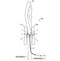
- FIG. 5 is a diagram illustrating the overall configuration of the measurement apparatus 200.
- the difference between the measuring device 200 and the measuring device 100 is that (1) The point that each of the light source 2 and the detector (light detection unit) 3 is one, (2) The bracket (clip) 20L, 20R and the hinge (clip) 21 are provided.
- the light source 2 has the same function as either the light source 2a or the light source 2b in the measurement apparatus 100.
- the detector 3 has the same function as the detector 3a or the detector 3b in the measuring apparatus 100.
- the measuring apparatus 200 includes brackets (clips) 20 ⁇ / b> L and 20 ⁇ / b> R and a hinge (clip) 21 for sandwiching a part of the earlobe.
- the suction mechanism 1 is provided at a position where a part of the earlobe sandwiched between the brackets 20L and 20R can be sucked through the suction hole 5.
- the hinge 21 includes a spring for causing the brackets 20L and 20R to function as a clip.
- the suction hole 5 of the suction mechanism 1 is provided at a position (upper side in the figure) facing the exhaust hole 4 (lower side in the figure), similarly to that shown in FIG. It has been.
- the optical measurement can be performed by irradiating a part of the earlobe sucked into the suction mechanism 1 with light.
- the earlobe has few blood vessels and less fluorescence as background due to AGEs accumulated in the blood vessel wall, more accurate measurement can be performed.
- the skin of the earlobe is very thin compared to other parts, so that the state of the stratum corneum, epidermis layer and / or dermis layer can be confirmed without changing the internal volume of the suction mechanism 1 so much. It is.
- the skin state including at least the epidermis layer or the dermis layer can be easily confirmed.
- the suction mechanism 1 by controlling the amount of skin sampling in the suction mechanism 1, it is possible to digitize biological information based on information in the skin depth direction, and show different behaviors at the measurement site and measurement position.
- the detection of the fluorescent substance is obtained as intensity information, and the skin aging degree can be visualized based on this information.
- the glycation state of the skin can be monitored, and the degree of aging of the skin can be determined using fluorescence generated from AGEs accumulated in the epidermis layer and / or dermis layer of the skin. It becomes possible to monitor.
- the measuring apparatuses 100 and 200 it is possible to visualize the effect confirmation of the anti-aging cosmetics by aging measurement of the skin due to glycation, which could not be realized by the conventional measuring apparatus.
- control unit 8 may be realized by hardware by a logic circuit formed on an integrated circuit (IC chip), or may be a CPU (Central Processing Unit). You may implement
- IC chip integrated circuit
- CPU Central Processing Unit
- the measuring apparatuses 100 and 200 include a CPU that executes instructions of a program that realizes each function, a ROM (Read Memory) that stores the program, a RAM (Random Access Memory) that expands the program, and the program And a storage device (recording medium; for example, the recording unit 9) such as a memory for storing various data.
- An object of the present invention is a recording medium in which the program code (execution format program, intermediate code program, source program) of the control program of the measuring apparatuses 100 and 200, which is software for realizing the functions described above, is recorded so as to be readable by a computer. Can also be achieved by reading the program code recorded on the recording medium and executing it by the computer (or CPU or MPU).
- Examples of the recording medium include tapes such as magnetic tapes and cassette tapes, magnetic disks such as floppy (registered trademark) disks / hard disks, and disks including optical disks such as CD-ROM / MO / MD / DVD / CD-R.
- IC cards including memory cards
- semiconductor memories such as mask ROM / EPROM / EEPROM / flash ROM, or PLD (Programmable logic device) or FPGA (Field Programmable Gate Array) Logic circuits can be used.
- the measuring devices 100 and 200 may be configured to be connectable to a communication network, and the program code may be supplied via the communication network.
- the communication network is not particularly limited as long as it can transmit the program code.
- the Internet intranet, extranet, LAN, ISDN, VAN, CATV communication network, virtual private network, telephone line network, mobile communication network, satellite communication network, and the like can be used.
- the transmission medium constituting the communication network may be any medium that can transmit the program code, and is not limited to a specific configuration or type.
- wired lines such as IEEE 1394, USB, power line carrier, cable TV line, telephone line, and ADSL (Asymmetric Digital Subscriber Line) line
- infrared rays such as IrDA and remote control
- Bluetooth registered trademark
- IEEE 802.11 wireless High Data Rate
- HDR High Data Rate
- NFC Near Field Communication
- DLNA Digital Living Network Alliance
- radio such as a mobile phone network, satellite line, and terrestrial digital network.
- the measuring device of the present invention can be expressed as follows.
- the measurement device of the present invention includes a sampling mechanism (skin sampling member) that samples a part of the skin, and excitation light that irradiates a part of the skin (location, measurement target part) sampled by the sampling mechanism.
- a sampling mechanism skin sampling member
- excitation light that irradiates a part of the skin (location, measurement target part) sampled by the sampling mechanism.
- the fluorescence information includes physical property information derived from the substance such as fluorescence intensity, detected wavelength information, and half-value width.
- the sampling mechanism may include a structure whose size is variable in order to select (sample) the target layer. More specifically, in the measuring apparatus according to the present invention, the sampling mechanism includes a surface other than the surface that irradiates the excitation light, the surface that transmits the excitation light, the surface that detects fluorescence, and the surface that sucks skin. It may be possible to change the length (size) of the sides of the two side surfaces.
- the sampling structure may use a clip-type measuring mechanism particularly in the earlobe. More specifically, the measurement apparatus of the present invention is the above sampling mechanism, and in particular, an excitation light irradiating unit that clips a part of the earlobe and irradiates the region with excitation light, and the living body is irradiated with the excitation light You may have a sensing mechanism provided with the light-receiving part which light-receives the fluorescence which arises by this.
- Another advantage of the measurement is that the earlobe has fewer blood vessels and less fluorescence as background due to AGEs accumulated in the blood vessel wall. It is a merit for measurement that the skin is very thin compared to other parts.
- One side of this clip is connected to the excitation light from the light emitting device with an optical fiber, and the other side of the clip is an optical fiber connected to the light receiving unit that receives the fluorescence generated by irradiating the living body with the excitation light irradiation unit. It may be connected.
- the excitation light may have a wavelength range suitable for measuring a late saccharification reaction product.
- AGEs from a specific position on the skin can be measured.
- the inventor of the present application has newly found that the fluorescence intensity of AGEs increases in skin that has undergone advanced glycation. Therefore, it is useful to realize a measuring device that measures AGEs as a skin sensor.
- the measuring apparatus described above it is also possible to monitor the glycation state of the skin, and using fluorescence generated from glycated substances (AGEs) accumulated in the epidermis layer and / or dermis layer of the skin, It is also possible to monitor the degree of aging.
- AGEs glycated substances
- the degree of aging it is possible to know from which layer of skin the fluorescence obtained from the amount of sampling, so it becomes possible to monitor the health of the skin, and anti-glycation cosmetics The effects and efficacy can be confirmed quickly and easily.
- the housing may have a portion having elasticity between at least a light-irradiated surface and a surface opposite to the surface.
- the entire housing may be made of an elastic material.
- the volume inside the housing is variable.
- Patent Documents 2 and 3 detect percutaneous (skin) fluorescence as reflected light, and the apparatus is large.
- the measurement site is unspecified as to where the fluorescence information is obtained from the percutaneous region.
- the skin sampling member of the present invention has at least one surface other than the light irradiation surface to which the light of the housing is irradiated in addition to the above configuration. A part of may be shielded from light.
- the measuring device of the present invention includes the skin sampling member, a light source that irradiates a part of the skin sucked into the housing through the suction hole, and light on the part of the skin. You may provide the photon detection part which detects the light produced by irradiating.
- the measurement is performed by irradiating a part of the skin sucked into the housing by the light source and detecting the light generated by the light detection unit irradiating the part of the skin.
- a device can be realized.
- the detection result (physical property information or physical quantity) of the light detection unit includes, for example, the detected light intensity, its half-value width, the detected light wavelength, skin reflectance, skin transmittance, and the like.
- Various physical property information derived from a substance contained in a part of is included.
- the discrimination method described in Patent Document 1 has a secondary problem that the state of the stratum corneum (or stratum corneum) can be confirmed, but the state of the epidermis layer and / or the dermis layer cannot be confirmed.
- the elasticity of the skin is not only the state of the stratum corneum which is only 0.02 mm thick as shown in FIG. 10 (a), but also the epidermis layer (thickness 0.07 to 0.2 mm), and the dermis. It depends on the state of the layer (thickness 2 mm).
- the dermis layer is composed of 70% or more of collagen fibers, but the late saccharification reaction products (AGEs) are crosslinked with the collagen fibers. By the crosslinking with AGEs, the three-dimensional network structure of collagen fibers is destroyed, and fibroblasts, hyaluronic acid and the like are reduced.
- crosslinking by AGEs also destroys the structure of the base layer in the boundary of an epidermis layer and a dermis layer, and the boundary between a dermis layer and an epidermis layer will also become indistinct. As a result, the elasticity of the skin is lowered, and the dullness of the skin progresses due to the color problem of AGEs.
- the measuring apparatus of the present invention may include a pump that decompresses the inside of the housing through the exhaust hole (of the skin sampling member). good.
- the inside of the casing can be decompressed using the pump, and a part of the skin can be sucked into the casing through the suction hole.
- the amount of skin sucked into the housing can be adjusted by adjusting the negative pressure inside the housing by the pump.
- the skin sampling member of the present invention it is possible to measure fluorescence derived from AGEs present in the stratum corneum, epidermis layer and / or dermis layer. For this reason, the AGEs present in the stratum corneum, epidermis layer and / or dermis layer are obtained by previously associating the intensity of fluorescence to be detected with the amount of AGEs present in the stratum corneum, epidermis layer and / or dermis layer. It is also possible to specify the amount. Further, according to the above configuration, it becomes possible to know which part of the stratum corneum, epidermis layer and / or dermis layer is glycated, and confirms the effect of cosmetics. Can be used.
- Patent Documents 2 and 3 detect percutaneous fluorescence as reflected light, and the apparatus is large.
- the measurement site is unspecified as to where the fluorescence information is obtained from the percutaneous region.
- the amount of skin to be sampled can be adjusted by adjusting the degree of pressure reduction of the pump, so that the secondary problems as described above can be easily solved. You can also
- Patent Documents 2 and 3 also have a secondary problem that the obtained results have poor quantitativeness because the fluorescence intensity varies greatly when blood vessels are present at the measurement site.
- the skin can be sampled by avoiding blood vessels present in the dermis layer by adjusting the degree of pressure reduction of the pump, so the secondary problem as described above.
- the point can also be solved.
- the measurement method of the present invention is a measurement method using the skin sampling member, wherein a decompression step of decompressing the inside of the housing through the exhaust hole, and through the suction hole in the decompression step.
- a light irradiating step for irradiating a part of the skin sucked into the housing and light detection for detecting light generated by irradiating a part of the skin in the light irradiating step And a process.
- the inside of the casing is decompressed through the exhaust hole. Therefore, a part of the skin can be sucked into the housing by bringing the suction hole close to the specific part of the skin and reducing the pressure inside the housing. Therefore, the specific site
- the light irradiation step In the light irradiation step, light is irradiated to a part of the skin sucked into the housing through the suction hole in the pressure reduction step. Furthermore, in the light detection step, light generated by irradiating a part of the skin with light in the light irradiation step is detected. Therefore, the above optical measurement is possible. For this reason, the time required for the procedure for confirming the state of the skin can be shortened compared with the discrimination method described in Patent Document 1.
- the skin condition including at least the epidermis layer or the dermis layer can be easily confirmed.
- the pressure inside the housing is such that the most part of the skin is composed of the stratum corneum, and most of the skin is composed of the stratum corneum and It may be at least variable up to a second size that is composed of a skin layer.
- the pressure inside the housing is at least variable from the first size to the second size.
- the first size is such a size that most of the skin is composed of a stratum corneum
- the second size is that most of the skin is composed of a stratum corneum and an epidermis layer. It is such a size.
- the pressure inside the casing is the first magnitude
- most of the part of the skin sucked into the casing can be made of the stratum corneum.
- the pressure inside the housing is the second magnitude
- most of the skin sucked into the housing can be composed of the stratum corneum and the epidermis layer.
- the amount of AGEs present in the stratum corneum and / or epidermis layer is specified by associating the intensity of fluorescence to be detected with the amount of AGEs present in the stratum corneum and / or epidermis layer in advance. Is also possible.
- the inventor of the present application newly found that the fluorescence intensity of AGEs increases in the skin that has advanced glycation. Therefore, according to the above configuration, it is possible to know which part of the stratum corneum and / or epidermis layer is saccharified, and it is possible to use the measuring device at the site of counseling, such as confirming the effect of cosmetics. It becomes.
- the intensity of the fluorescence detected by the light detection unit when the pressure inside the housing is the second magnitude, and the pressure inside the housing are the first pressure.
- the detection data analysis unit detects the fluorescence intensity detected when the pressure inside the housing is the second magnitude and when the pressure inside the housing is the first magnitude.
- the intensity of the fluorescence generated from the skin layer is specified based on the difference between the intensity of the fluorescence and the intensity of the fluorescence.
- melanin is a pigment (black to yellow) made in melanocytes (pigment cells) present in the basal layer portion of the epidermis shown in FIG.
- melanin does not stay in melanocytes, but is transferred to epidermal cells and is turned up to the stratum corneum on the outermost surface of the skin by turnover called skin turnover.
- stains can be formed, epidermal cells containing melanin may remain in the basal layer as they are, or melanocytes themselves may migrate into the dermis. This is also said to be a problem caused by abnormalities in the keratinocytes present in the epidermis.
- stains such as liver spots, senile pigment spots, and nevus, and it is known that the distribution of melanin is different.
- the distribution of melanin in the skin covers a wide range not only to melanocytes but also to the epidermis and dermis layers.
- melanin contained in the epidermis layer affects the detection result of light generated by irradiating a part of the skin with light.
- the pressure inside the casing is such that the part of the skin includes at least a dermis layer because the pressure is such that most of the part of the skin is composed of a stratum corneum. It may be variable at least up to the third size.
- the pressure inside the housing is at least variable from the first size to the third size.
- the first size and the second size are as described above
- the third size is a size such that at least the dermis layer is included in a part of the skin.
- At least a dermis layer can be included in a part of the skin sucked inside.
- the AGEs present in the stratum corneum, epidermis layer and / or dermis layer are obtained by previously associating the intensity of fluorescence to be detected with the amount of AGEs present in the stratum corneum, epidermis layer and / or dermis layer. It is also possible to specify the amount.
- the intensity of the fluorescence detected by the light detection unit when the pressure inside the housing is the third magnitude, and the pressure inside the housing are the first pressure.
- the detection data analysis unit detects when the fluorescence intensity detected when the pressure inside the housing is the third magnitude and when the pressure inside the housing is the first magnitude. Based on the difference between the fluorescence intensity and the fluorescence intensity, the fluorescence intensity generated from the dermis layer is specified.
- the state of the dermis layer (or skin) can be confirmed by associating the intensity of the fluorescence generated from the dermis layer with the state of the dermis layer (or skin) in advance.
- the fluorescence generated from the dermis layer since the difference between the fluorescence intensity detected at the third magnitude and the fluorescence intensity detected at the first magnitude is taken, the fluorescence generated from the dermis layer In addition, it is possible to reduce the influence of the reflected light of the light irradiated on a part of the skin.
- the wavelength of the light emitted from the light source may be within a range in which late saccharification reaction products (AGEs) can be detected.
- AGEs late saccharification reaction products
- AGEs can be detected by the above configuration.
- strength of the fluorescence derived from AGEs increases, the progress of saccharification of skin can be confirmed. Therefore, it is useful to realize a measuring device that detects AGEs.
- the measuring device of the present invention may further include another light source that irradiates a part of the skin with near infrared light or infrared light.
- oxyhemoglobin can be detected and veins can be detected by irradiating the skin surface with near infrared light from another light source.
- reduced hemoglobin can be detected and an artery can be detected.
- the measuring device of the present invention includes a clip that sandwiches a part of the earlobe, and the skin sampling member is located at a position where a part of the earlobe sandwiched between the clips can be sucked through the suction hole. It may be provided.
- the earlobe has few blood vessels and less fluorescence as background due to AGEs accumulated in the blood vessel wall, more accurate measurement can be performed.
- the skin of the earlobe is very thin compared to other parts, so it is possible to check the state of the stratum corneum, epidermis layer and / or dermis layer without changing the internal volume of the housing much. is there.
- the sampling member, measuring apparatus, and measuring method of the present invention can be applied to a monitoring apparatus that can monitor the glycation state of the skin, which could not be achieved by conventional techniques. Further, the present invention can also be applied to a monitoring device that monitors the health condition of the skin that anyone can use easily and accurately. Therefore, in the confirmation of the effects and efficacy of anti-glycated cosmetics, it is expected to promote the acquisition of evidence, and application as a skin care monitoring device is expected.
- Suction mechanism skin sampling member, housing
- 2a Light source 2b Light source (another light source) 3, 3a, 3b detector (light detector) 4 Exhaust hole 5
- Pump 8 Control part 9 Recording part 10
- Signal conversion part 11 Display part 20L, 20R Bracket (clip) 21 Hinge (clip) 81
- Pump control unit 82
- Light source control unit 83
- Detection data analysis unit 84 Display control unit 100, 200 Measuring device T
- Translucent unit S Light blocking unit
- SUF1 Surface SUF2 Surface (surface irradiated with light, light irradiation surface)
- SUF3 surface opposite surface
- SUF4 SUF5 surface
Landscapes
- Health & Medical Sciences (AREA)
- Life Sciences & Earth Sciences (AREA)
- Physics & Mathematics (AREA)
- Pathology (AREA)
- General Health & Medical Sciences (AREA)
- Public Health (AREA)
- Animal Behavior & Ethology (AREA)
- Veterinary Medicine (AREA)
- Surgery (AREA)
- Medical Informatics (AREA)
- Molecular Biology (AREA)
- Biophysics (AREA)
- Engineering & Computer Science (AREA)
- Biomedical Technology (AREA)
- Heart & Thoracic Surgery (AREA)
- General Physics & Mathematics (AREA)
- Immunology (AREA)
- Biochemistry (AREA)
- Analytical Chemistry (AREA)
- Chemical & Material Sciences (AREA)
- Spectroscopy & Molecular Physics (AREA)
- Dermatology (AREA)
- Optics & Photonics (AREA)
- Nuclear Medicine, Radiotherapy & Molecular Imaging (AREA)
- Emergency Medicine (AREA)
- Investigating, Analyzing Materials By Fluorescence Or Luminescence (AREA)
- Investigating Or Analysing Materials By Optical Means (AREA)
- Measuring And Recording Apparatus For Diagnosis (AREA)
Abstract
透光性を有する吸引機構(1)と、吸引機構(1)に設けられ、肌を吸引するための吸引孔(5)と、吸引機構(1)に設けられ、吸引機構(1)の内部を減圧するための排気孔(4)とを備えている。
Description
本発明は、肌をサンプリングする肌サンプリング部材、該肌サンプリング部材を備えた測定装置、および上記肌サンプリング部材を用いた測定方法に関する。
従来、抗糖化(抗加齢)化粧品として、肌に蓄積したAGEs(Advanced Glycation Endproducts;後期糖化反応生成物)の低減を目的としたものが商品化されている。このAGEsは、タンパク質と、糖質や脂質との非酵素的糖付加反応(メイラード反応)により形成される最終生成物であり、黄褐色を呈し、その一部は蛍光を発する物質である。また、AGEsは、近くに存在する構造蛋白質と結合して架橋を形成する性質を有している。特にAGEsと真皮を構成しているコラーゲンとの架橋は、皮膚の弾力性を低下させ、またくすみの原因としても問題となっている。
肌の状態を測定する方法としては、肌の皮脂層や角質層の水分量や油分量を測る方法や、表面電位を測る方法などが知られているが、何れも皮膚表面の情報を評価しているに過ぎないという問題点がある。
肌の状態を測定するその他の方法としては、特許文献1に開示された肌の鑑別方法がある。
この鑑別方法では、粘着テープを用いて角質細胞をサンプリングするテープストリッピング法で皮膚より採取した角層細胞に紫外線を照射し、該紫外線によって発光する蛍光の強度によって、角層細胞におけるβシート型のケラチンの存在割合の推定および/または皮膚柔軟性を鑑別している。
なお、肌の状態を測定するその他の方法としては、特許文献2または3に開示された技術がある。これらの文献に記載の技術では、肌に照射した光の反射光を検出している。
しかしながら、上記特許文献1に記載の鑑別方法では、角質細胞から得られる肌の知見しか得られないという問題点がある。また、同鑑別方法では、角質細胞を採取してから角質細胞からの蛍光を測定するまでの手続が煩雑であるという問題点もある。
例えば、上記特許文献1に記載の鑑別方法は、
(1)肌から粘着テープを用いて角質細胞を採取する工程、
(2)粘着テープを有機溶剤で半日以上かけて溶かす工程、
(3)得られた角質細胞でプレパラートを作成する工程、および、
(4)蛍光分光光度計を用いて、プレパラートの蛍光を測定する工程、の少なくとも4つの工程を含んでいる。このため、被験者が自分の肌の状態を確認するまでの手続が非常に煩雑であるという問題点がある。
(1)肌から粘着テープを用いて角質細胞を採取する工程、
(2)粘着テープを有機溶剤で半日以上かけて溶かす工程、
(3)得られた角質細胞でプレパラートを作成する工程、および、
(4)蛍光分光光度計を用いて、プレパラートの蛍光を測定する工程、の少なくとも4つの工程を含んでいる。このため、被験者が自分の肌の状態を確認するまでの手続が非常に煩雑であるという問題点がある。
また、上記鑑別方法では、被験者が自分の肌の状態を確認したいと思ってから、1日以上経過した後でないと、肌の鑑別結果が得られない。よって、化粧品のカウンセリングを行う際、皮膚組織を採取後、1日以上経過した後にカウンセリングを実施せざるを得ない。このため、自分の肌の鑑別結果をもとにタイムリーな意見交換が行えず、カウンセリングの効率も悪くなってしまう。
一方、特許文献2および3に記載の技術では、肌の反射光を検出する構成なので、その手続は簡単であるものの、何れも肌の奥深くの表皮層または真皮層を含む肌の状態を検知することは難しいという問題点がある。
本発明は、上記の問題点を解決するためになされたもので、少なくとも表皮層または真皮層を含む肌の状態を確認する目的で肌の一部を簡単にサンプリングすることが可能になる肌サンプリング部材、該肌サンプリング部材を備えた測定装置、および上記肌サンプリング部材を用いた測定方法を提供することを目的とする。
本発明の肌サンプリング部材は、上記の課題を解決するために、透光性を有する材料で構成された筐体と、上記筐体に設けられ、肌を吸引するための吸引孔と、上記筐体に設けられ、上記筐体の内部を減圧するための排気孔とを備えていることを特徴とする。
上記構成によれば、吸引孔を生体の特定部位(測定対象部)に接触させて、排気孔を介して筐体の内部を減圧することにより、吸引孔を介して肌の一部を筐体の内部に吸引することができる。よって、肌の特定部位を簡単な手続でサンプリングすることができる。
測定対象部は、被験者の腕、手首、耳朶、指尖、掌、頬、二の腕の内側などを例示することができる。
また、筐体は、透光性を有しているので、筐体の内部に吸引された肌の一部(肌の特定部位)に光を照射することで、肌の一部に光が照射されることにより生じる光を光学的に測定することが可能となる。
なお、肌の一部に光が照射されることにより生じる光としては、肌の一部に照射した光が反射した反射光、肌の一部に照射した光が肌を透過した透過光、または、肌の一部に励起光(光)を照射することにより生じた蛍光などを挙示できる。
また、上記の光学的な測定を行うには、サンプリングした肌の一部に光を照射するだけで良いので、特許文献1に記載の鑑別方法と比較して肌の状態を確認する手続を簡単にすることができる。
さらに、筐体の内部に肌の一部を吸引するという簡単な方法であるものの、筐体の内部の容積を適度に大きくすれば、吸引される肌の一部に表皮層または真皮層が含まれるようにすることも可能である。
以上より、少なくとも表皮層または真皮層を含む肌の状態を確認する目的で肌の一部を簡単にサンプリングすることが可能になる。
本発明の肌サンプリング部材は、以上のように、透光性を有する材料で構成された筐体と、上記筐体に設けられ、肌を吸引するための吸引孔と、上記筐体に設けられ、上記筐体の内部を減圧するための排気孔とを備えている構成である。
それゆえ、少なくとも表皮層または真皮層を含む肌の状態を確認する目的で肌の一部を簡単にサンプリングすることが可能になるという効果を奏する。
本発明の他の目的、特徴、および優れた点は、以下に示す記載によって十分分かるであろう。また、本発明の利点は、添付図面を参照した次の説明で明白になるであろう。
本発明の一実施形態について図1~図10に基づいて説明すれば、次の通りである。以下の特定の項目で説明する構成以外の構成については、必要に応じて説明を省略する場合があるが、他の項目で説明されている場合は、その構成と同じである。また、説明の便宜上、各項目に示した部材と同一の機能を有する部材については、同一の符号を付し、適宜その説明を省略する。
〔1.測定装置〕
まず、図1および4に基づき、本発明の一実施形態である測定装置100の全体構成について説明する。図1は、測定装置100の全体構成を示す図である。また、図4は、測定装置100の一実施例(以下、ポータブル型測定装置という)を示す図である。
まず、図1および4に基づき、本発明の一実施形態である測定装置100の全体構成について説明する。図1は、測定装置100の全体構成を示す図である。また、図4は、測定装置100の一実施例(以下、ポータブル型測定装置という)を示す図である。
なお、本実施形態では、測定対象となる被験者の肌の一部(または測定対象部)より得られた蛍光の強度を検出(特定)する測定装置100について説明する。
しかしながら、測定装置100が特定するデータは、このような蛍光の強度のみに限られず、その他の物性情報(または物理量)を特定するようにしても良い。
例えば、一般に、肌の一部に光が照射されることにより生じる光としては、照射した光が反射した反射光、照射した光が肌を透過した透過光、または、励起光(光)を照射することにより生じた蛍光(肌に含まれる物質に由来する蛍光)などを挙示できる。
よって、測定装置100は、本実施形態のような光の強度の他、例えば、その半値幅、検出された光の波長、肌の反射率、肌の透過率などといった、肌の一部に含まれる物質などに由来する物性情報(または物理量)のいずれかを特定するものであれば良い。
図1に示すように、測定装置100は、吸引機構(肌サンプリング部材、筐体)1、光源2a、光源(別の光源)2b、検出器(光検出部)3a、3b、導管6、ポンプ7、制御部8、記録部9、信号変換部10および表示部11を備える。
次に、図4の右下には、ポータブル型測定装置測定の外観を示している。なお、同図では、ポータブル型測定装置における、吸引機構1、光源2a、検出器3a、3bの配置の一例を示している。
また、図4の「TOP view」は、ポータブル型測定装置を上面からみたときの、吸引機構1、光源2a、検出器3a、3bの配置の一例を示している。なお、図4に示す吸引機構1では、図1に示す吸引機構1とは、吸引孔5の位置が異なっており、吸引孔5は、排気孔4(同図の下側)と対向する位置(同図の上側)に設けられている。このように、吸引機構1の吸引孔5は、排気孔4と対向する位置に設けられていても良い。
一方、図4の「SIDE view」は、ポータブル型測定装置の内部を斜め横からみたときの、吸引機構1、光源2a、検出器3a、3b、ポンプ7の配置の一例を示している。
(吸引機構1)
図1に示すように、本実施形態における吸引機構1の形状は、略直方体形状である。しかしながら、吸引機構1の形状は、略直方体形状に限られず、肌の一部を吸引できる形状であればどのような形状であっても良い。例えば、上記の略直方体形状、略立方体形状、角錐台形状あるいは円錐台形状、または、これらの各形状の角を丸めたような形状など様々な形状を採用できる。
図1に示すように、本実施形態における吸引機構1の形状は、略直方体形状である。しかしながら、吸引機構1の形状は、略直方体形状に限られず、肌の一部を吸引できる形状であればどのような形状であっても良い。例えば、上記の略直方体形状、略立方体形状、角錐台形状あるいは円錐台形状、または、これらの各形状の角を丸めたような形状など様々な形状を採用できる。
また、吸引機構1における6つの表面のうち、5つの表面が、表面SUF1~表面SUF5と称する。また、略直方体形状の残りの1つの表面の側(同図の下側)は開放され、肌を吸引するための吸引孔5を為している。さらに、表面SUF1には、導管6を介してポンプ7と接続するための排気孔4が設けられている。すなわち、排気孔4は、吸引機構1の内部から気体(例えば、空気)を排気する(吸引機構1の内部を減圧する)ための孔である。
本実施形態の吸引機構1の構成材料は、透光性を有する石英ガラスである。例えば、石英セル容器の一部に孔(排気孔4)を開けて作製する。なお、吸引機構1の構成材料は、石英ガラスに限られず、透光性を有する樹脂材料やセラミックスなどであっても良い。
吸引機構1の一実施例(石英セル容器)を図2に示す。図2の(a)は、吸引機構1の外観を示す斜視図である。図2の(b)は、吸引機構1の外観を示す側面図である。
本実施形態の吸引機構1は、図1に示すように、長さaが、20mm程度であり、長さbが、25mm程度であり、長さcが、10mm程度である(例えば、図2に示す石英セル容器を構成する石英板の厚さは無視している)。
吸引機構1の内部の容積が一定の場合に、吸引される肌の量を多くするには、吸引機構1の内部の負圧を大きくすれば良い。
しかしながら、吸引機構1の内部の負圧を大きくしたときに、吸引機構1の内部に吸引される肌の一部に少なくとも真皮層が含まれるようにするには、長さaは、2~5mm以上、長さbおよび長さcは、共に少なくとも4~10mm以上が必要である。例えば、長さbおよび長さcを有する吸引孔5でサンプリングする肌の量の半分が、吸引される肌の断面の厚さ(深さ)に対応すると考える。
このとき、真皮層の厚さは、2~5mm程度であるから、長さaは、少なくとも2~5mm程度、長さbおよび長さcは、それぞれ真皮層の厚さの2倍程度、すなわち、少なくとも4~10mm程度である必要があることになる。
同様の考え方から、吸引機構1の内部の負圧を大きくしたときに、吸引機構1の内部に吸引される肌の一部に少なくとも真皮層が含まれるようにするには、吸引機構1の内部の容積は、少なくとも、32mm3~500mm3以上である必要があることになる。
吸引機構1の内部の容積が一定のとき、サンプリングする肌の量を調整するには、吸引機構1の内部の圧力の大きさを調整すれば良い。このとき、吸引機構1の内部の容積に応じた上限が存在するものの、圧力が高ければ高いほど、サンプリングされる肌の量は大きくなり、圧力が低ければ低いほどサンプリングされる肌の量は小さくなる。
一方、吸引機構1の内部の圧力が一定のとき、サンプリングする肌の量を調整する方法としては、
(1)内部の容積が異なる吸引機構1を複数用意し、交換可能とする方法や、
(2)吸引機構1そのものの内部の容積を可変とする方法などが考えられる。
(1)内部の容積が異なる吸引機構1を複数用意し、交換可能とする方法や、
(2)吸引機構1そのものの内部の容積を可変とする方法などが考えられる。
上記(1)の場合、吸引機構1の内部の容積を変更する方法としては、吸引機構1全体の大きさを変更する方法や、吸引機構1が石英セル容器からなる場合、石英セル容器を構成する石英板の厚みを厚くしたり、薄くしたりする方法などが考えられる。
一方、上記(2)の場合、吸引機構1は、その内部の容積が可変となるような構造を設ける方法が考えられる。例えば、図3には、このように内部の容積が可変の吸引機構1の例を模式的に示している。
以上のように、吸引機構1の内部の容積を可変とすることにより、サンプリングする肌の量を変更することが可能となる。これにより、ほぼ同じ箇所で、肌の表面から、角質層の領域、表皮層の領域、真皮層の領域までのいずれをサンプリングするのかを選択することができる。
ところで、上記特許文献1に記載の鑑別方法では、角質細胞(角質層)の状態は確認できるものの、表皮層および/または真皮層の状態を確認することはできないという副次的な課題がある。
例えば、肌の弾力性は、図10の(a)に示す高々0.02mmの厚さしかない角質層の状態だけではなく、表皮層(厚さ0.07~0.2mm)、さらには真皮層(厚さ2mm)の状態にも左右される。真皮層はその70%以上がコラーゲン繊維で構成されているが、後期糖化反応生成物(AGEs)はこのコラーゲン繊維と架橋してしまう。このAGEsによる架橋によって、コラーゲン繊維の3次元網目構造が崩壊し、繊維芽細胞、ヒアルロン酸などが低減する。また、AGEsによる架橋によって、表皮層と真皮層との境にある基底層の構造も崩れてしまい、真皮層と表皮層との境界も不明瞭となってしまう。この結果、肌の弾力性が低下し、AGEsのもつ色合いの問題から、肌のくすみが進行することになる。
また、図10の(b)に示すように、角質層は14日でターンオーバーを繰り返すのに対して、表皮は28日、真皮は5~6年でターンオーバーを繰り返すことからも、スキンケアにおいて、表皮および真皮の健康状態は無視できないことが明白である。
そこで、吸引機構1は、上記の副次的な課題を解決するために、吸引機構1の内部の圧力(または容積)は、下記の第1の大きさから第2の大きさまで少なくとも可変となっていても良い。あるいは、吸引機構1の内部の圧力(または容積)は、第1の大きさから、第3の大きさまで少なくとも可変となっていても良い。
ここで、第1の大きさは、肌の一部のほとんどが角質層からなるような大きさである。また、第2の大きさは、肌の一部のほとんどが角質層および表皮層からなるような大きさである。さらに、第3の大きさは、肌の一部に少なくとも真皮層が含まれるような大きさである。
よって、吸引機構1の内部の圧力(または容積)が第1の大きさのときは、吸引機構1の内部に吸引される肌の一部のほとんどが角質層からなるようにすることができる。また、吸引機構1の内部の圧力(または容積)が第2の大きさのときは、吸引機構1の内部に吸引される肌の一部のほとんどが角質層および表皮層からなるようにすることができる。さらに、吸引機構1の内部の圧力(または容積)が第3の大きさのときは、吸引機構1の内部に吸引される肌の一部に少なくとも真皮層が含まれるようにすることができる。
これにより、例えば、角質層、表皮層および/または真皮層に存在するAGEs由来の蛍光を測定することが可能となる。このため、検出する蛍光の強度と、角質層、表皮層および/または真皮層に存在するAGEsの量とを予め対応づけておくことにより、角質層、表皮層および/または真皮層に存在するAGEsの量を特定することも可能になる。また、上記構成によれば、角質層、表皮層および/または真皮層のどの部位が糖化しているのかを知ることも可能となり、化粧品の効果を確認するなど、カウンセリングの現場での測定装置の利用が可能となる。
次に、吸引機構1自体の内部の容積を可変とするには、吸引機構1全体を、透光性かつ弾性を有する材料(例えば、シリコーンゴムなど)で構成すれば良い。あるいは、吸引機構1における6つの表面の部分のうちの一部を、弾性を有する材料(例えば、シリコーンゴムなど)で構成し、残りの一部を、石英ガラス、硬質性の樹脂材料またはセラミックスなどで構成しても良い。
例えば、吸引機構1における6つの表面のうち、互いに対向する少なくとも1組の表面(光が照射される側の面)SUF2および表面(対向する側の面)SUF3の各部を、透光性を有する硬質性の樹脂材料で構成する。一方、表面SUF2と表面SUF3との間を結合する表面SUF1、表面SUF4および表面SUF5の各部(弾性を有する部分)を、シリコーンゴムなどで構成する。
これにより、弾性を有する部分の存在により、少なくとも吸引機構1の光が照射される側(表面SUF2の側)と、それに対向する側(表面SUF3の側)との間の距離が可変となる。言い換えれば、吸引機構1の内部の容積が可変となる。このため、吸引機構1の内部に吸引される肌の量を調整することができる。
よって、サンプリングする肌の量により、肌の角質層、表皮層および/または真皮層からの蛍光を測定することが可能となる。また、上記の構成により、ほぼ同じ箇所で、肌の断面方向(肌の表面からの深さ方向)に沿って存在する肌の角質層、表皮層および/または真皮層に存在するAGEs量を測定することも可能となる。
シリコーン原料組成物としては、信越化学工業株式会社製の「KJR632」等の市販品を用いることができる。シリコーン原料組成物は、上記成分以外に、得られるシリコーン樹脂の強度や透明度を損なわない程度に充填剤、耐熱材、可塑剤等を添加してもよい。
また、シリコーンゴムは、比較的低分子のオルガノポリシロキサンが架橋したシリコーンゴムであってもよい。
吸引機構1は、所期の形状に応じた適切な成形方法で上記シリコーン原料組成物を成形する。例えば、射出成形、押出成形、注型成形等により成形することができる。
なお、吸引機構1の透過率は、90%以上であることが好ましく、92%以上であると一層好ましい。ポリジメチルシロキサンで成形した吸引機構1の透過率は約94%、ポリジフェニルシロキサンで成形した吸引機構1の透過率は約92%であり、長期に使用してもその透過率は維持される。吸引機構1は、ポリジメチルシロキサンのような硬いシリコーン樹脂で成形されていると、膨張し難いうえ、紫外線などの短波長側で劣化し難く、光学特性を維持するのに適切である。
特に、吸引機構1がシリコーンゴム製であると、水分や低分子シロキサンのような揮発成分が残存し易いので、それらを揮発させることが好ましい。
以上説明した、吸引機構1によれば、吸引孔5を生体の特定部位(測定対象部)に接触させて、排気孔4を介して吸引機構1の内部を減圧することにより、吸引孔5を介して肌の一部を吸引機構1の内部に吸引することができる。よって、肌の特定部位を簡単な手続でサンプリングすることができる。
また、吸引機構1は、透光性を有しているので、吸引機構1の内部に吸引された肌の一部(肌の特定部位)に光を照射することで、肌の一部に光が照射されることにより生じる光を光学的に測定することが可能となる。
さらに、上記の光学的な測定を行うには、サンプリングした肌の一部に光を照射するだけで良いので、特許文献1に記載の鑑別方法と比較して肌の状態を確認する手続を簡単にすることができる。
また、上記の光学的な測定の測定結果は、サンプリングした肌の一部に光を照射してから瞬時に得られる。このため、特許文献1に記載の鑑別方法と比較して肌の状態を確認する手続に要する時間を短縮することができる。
さらに、吸引機構1の内部に肌の一部を吸引するという簡単な方法であるものの、吸引機構1の内部の容積を適度に大きくすれば、吸引される肌の一部に表皮層または真皮層が含まれるようにすることも可能である。
以上より、少なくとも表皮層または真皮層を含む肌の状態を簡単に確認する目的で肌をサンプリングすることが可能になる。
なお、測定装置100による測定対象部は、被験者の腕、手首、耳朶、指尖、掌、頬、二の腕の内側などを例示することができる。
図6に、このような測定対象部のうち、手の指先(指尖)、手首の血管のうち、血管が分岐している部分(手首血管分岐位置)、手首で血管の存在しない部分(手首血管未確認位置)、手のひら(血管未確認位置)のそれぞれの箇所からのAGEsによる蛍光のスペクトルの測定結果を示す。
同図では横軸に蛍光の波長(nm)、縦軸に蛍光の強度(a.u.)を示している。たとえば波長460nmあたりの蛍光の強度は、手の指先(指尖)で10,000a.u.以上、また血管が分岐している部分(手首血管分岐位置)においては、約9,000a.u.の値を示しており、顕著な蛍光のスペクトルが得られた。一方、手のひら(血管未確認位置)、手首で血管の存在しない部分(手首血管未確認位置)では、蛍光のスペクトルは得られるものの、手の指先(指尖)、および血管が分岐している部分(手首血管分岐位置)と比較して、大きな数値は得られなかった。分析箇所によって、これだけ蛍光の強度が異なることが分かる。
上記のように、手の指先(指尖)、および血管が分岐している部分(手首血管分岐位置)においては、特にAGEsが溜まりやすいことが分かった。つまり、AGEsの溜まりやすい箇所を測定位置として定めることで、より精度の高い正確なデータを得ることができることが分かる。
(吸引機構1の変形例)
次に、図8および9に基づき、上述した吸引機構1の変形例について説明する。
次に、図8および9に基づき、上述した吸引機構1の変形例について説明する。
ところで、上記の特許文献2および3に記載の技術は、反射光として経皮の蛍光を検出ており、装置も大掛かりある。また、経皮の何処から得られた蛍光の情報なのか測定部位も不特定であるという副次的な問題点がある。
そこで、同図に示すように、吸引機構1は、光が照射される表面(光照射面)SUF3以外の少なくとも一つの面の一部が遮光されていても良い(遮光部S)。
なお、吸引機構1に遮光部Sを設ける方法としては、蛍光を取り出さない部分を遮光性プラスチックで作製したり、透光性を有する材料の表面に遮光剤を塗布したりする方法が考えられる。
上記の構成によれば、吸引機構1の光が照射される光照射面以外の少なくとも一つの面の一部のうち、遮光されていない部分(透光部T)から出射される蛍光のみを選択して測定することが可能になる。よって、吸引機構1の内部に吸引された肌の一部のうち、特定部位(例えば、表皮層や真皮層)からの蛍光のみを選択して測定することが可能となる。
例えば、図8は、表皮層以外のほとんどは、遮光部Sで覆われている。よって、表皮層から透光部Tを介して出射される蛍光のみを選択的に検出できる。
一方、図9は、真皮層以外のほとんどは、遮光部Sで覆われている。よって、真皮層から透光部Tを介して出射される蛍光のみを選択的に検出できる。
なお、遮光部Sおよび透光部Tの配置は、吸引機構1の内部が一定の圧力のときに吸引される肌の量に応じて予め決定しておけば良い。
(光源2a)
光源2aは、LED(Light Emitting Diode)やLD(Laser Diode)などの半導体素子の他、ランプ光源などを利用することも可能である。
光源2aは、LED(Light Emitting Diode)やLD(Laser Diode)などの半導体素子の他、ランプ光源などを利用することも可能である。
光源2aから発する光の波長は、近紫外領域である315~400nmから可視光領域である315~600nmのものが適している。
なお、本実施形態では、近紫外領域の230nm以上365nm以下の波長か、青紫色領域の405nmの波長となっている。
このような波長の光を測定対象部の特定部位(例えば、血管など)に照射することにより、照射位置の血管壁の蓄積物からの蛍光が得られる。
また、光源2aから発する光の波長は、後期糖化反応生成物(AGEs)を検知することが可能な範囲内の波長であっても良い。
上記の構成により、AGEsを検知できる。なお、糖化が進んだ肌においては、AGEs由来の蛍光の強度が増加するので、肌の糖化の進み具合を確認できる。よって、AGEsを検知する測定装置を実現することは有用である。
AGEsには、現在知られているだけでも20ほどの種類があり、その中で光を照射すると蛍光を発するものがいくつかある。表1にその例を示す。
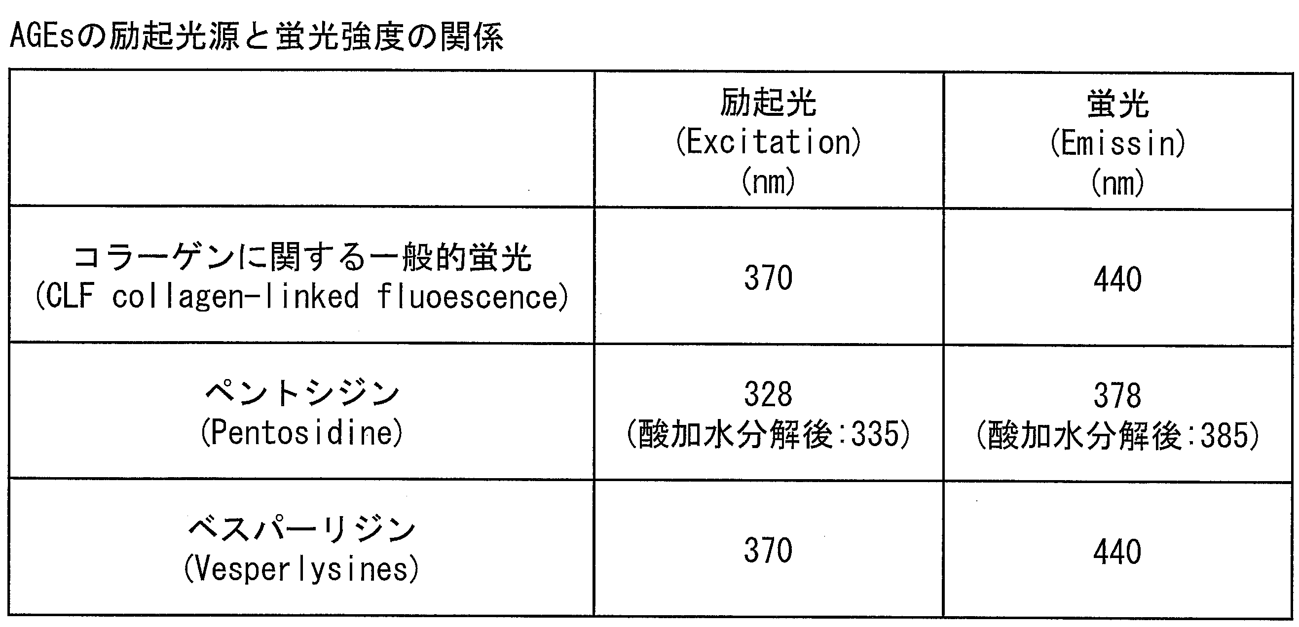
表1中、CLF(collagen-linked fluorescence)は、コラーゲンと結合したAGEsからの蛍光であり、総AGEs生産およびこれに付随するコラーゲン架橋の一般的な尺度として用いられる。
ペントシジンとべスパーリジンはAGEsの代表的な例である。ペントシジンはペントースと等モルのリジンとアルギニンが架橋した構造を有し、酸加水分解後に安定な蛍光性物質である。特に糖尿病の発症や末期の腎症において増加することが報告されている。ベスパーリジンはAGE化ウシ血清アルブミン(BSA)を酸加水分解した後、主要な蛍光性物質として単離され、2分子のリジンを架橋した構造を有している。
表1からもわかるように、励起光の波長としては、370nmまたはその近傍での波長が最も適しているが、AGEsの種類によって適応する励起光の幅としては、紫外光領域である315~400nmから可視光領域である315~600nmのものが適している。
このようにして蛍光を検出することで、血管から非侵襲的にAGEsの存在を確認することができる。
(光源2b)
次に、光源(別の光源)2bは、血管を可視化するための近赤外光源または赤外光源である。また、光源2bは、近赤外光と、赤外光とを切り替えて照射できる光源であることが好ましい。このような光源の例として、京セミ株式会社製「Multi-Wavelength LED KED694M31D」を例示することができる。
次に、光源(別の光源)2bは、血管を可視化するための近赤外光源または赤外光源である。また、光源2bは、近赤外光と、赤外光とを切り替えて照射できる光源であることが好ましい。このような光源の例として、京セミ株式会社製「Multi-Wavelength LED KED694M31D」を例示することができる。
血管を可視化(検知)する方法として、酸素と結合したオキシヘモグロビン(酸化ヘモグロビン)、酸素と結合していないデオキシヘモグロビン(還元ヘモグロビン)の赤色ないし赤外領域での吸光度の違いを利用し、血管の種類(静脈か動脈か)を特定して、AGEsを測定することも可能である。
例えば、静脈には還元ヘモグロビンが多く含まれるのに対し、動脈には酸化ヘモグロビンが多く含まれている。図7は酸化ヘモグロビンと還元ヘモグロビンの波長と吸光度の関係を示している。横軸に波長(nm)、縦軸に吸光度(a.u.)を示している。グラフでは805nmを境として、短波長側では還元ヘモグロビンが、長波長側では酸化ヘモグロビンの吸光度が高い。
つまり、805nmよりも長波長の光を照射すると、酸化ヘモグロビンの多く含まれている血管(動脈)が酸化ヘモグロビンの少ない血管(静脈)よりも明瞭に確認できる。その後、805nmよりも短波長の光を照射すると、それまで明瞭に見えていた酸化ヘモグロビンの多く含まれている血管、つまり還元ヘモグロビンの少ない血管(動脈)が不明瞭になるのに対し、還元ヘモグロビンの多く含まれている血管、つまり酸化ヘモグロビンの少ない血管(静脈)が明瞭になる。
今回は例として805nmを境にしてそれより長波長、短波長の光で説明したが、あくまでも長波長と短波長の相対的な吸光度の差を利用することで、還元ヘモグロビンと酸化ヘモグロビン、つまり静脈と動脈を区別して可視化することが理論上可能となる。つまり、酸化ヘモグロビンの吸光度が還元ヘモグロビンのそれより高い波長と、酸化ヘモグロビンの吸光度が還元ヘモグロビンのそれより低い波長とを用いることで、静脈と動脈の同定が可能となる。図7のデータに基づくと、805nmを境にしてそれより長波長、短波長の光を用いることにより、静脈と動脈を区別するには好適となる。
上記のことから、光源2bに600~1000nmの範囲の波長で、二種類以上の波長を用いることで、静脈と動脈を区別して可視化することができる。図7によれば、特に酸化ヘモグロビンを検出するための940nm前後の近赤外領域の光源と、還元ヘモグロビンを検出するための660nm前後の赤色領域の光源を備えることが望ましい。同一照射箇所において照射するこれら2種の波長を速やかに切り替えることで、その血管画像を比較し、動脈と静脈の同定が可能となる。
なお、近赤外光を発する光源と、赤外光を発する光源とを別々に設けても良い。例えば、近赤外LEDと、赤色LEDとを切り替えて点灯することで、吸引機構1の内部にサンプリングされた肌の一部に血管が含まれているのか、いないのかを確認することができる。近赤外LEDは、945nm前後(890~1010nm)の近赤外領域の波長を有する光を出射する光源である。近赤外光を皮膚表面に照射することにより、酸化ヘモグロビンを検出することができ、静脈を可視化できる。赤色LEDは、660nm前後(620~700nm)の赤色領域の波長を有する光を出射する光源である。赤色光を皮膚表面に照射することにより、還元ヘモグロビンを検出することができ、動脈を可視化できる。
(検出器3a、3b)
検出器3a、3bは、肌の一部から発生した蛍光を検出するものであり、単一または複数の受光素子を含んでいる。なお、検出器3a、3bは、受光素子だけでなく、例えば、蛍光分光光度計などのように分光器を備えていても良い。これにより、分光された蛍光に基づくより細かな検出データの解析が可能になる。
検出器3a、3bは、肌の一部から発生した蛍光を検出するものであり、単一または複数の受光素子を含んでいる。なお、検出器3a、3bは、受光素子だけでなく、例えば、蛍光分光光度計などのように分光器を備えていても良い。これにより、分光された蛍光に基づくより細かな検出データの解析が可能になる。
受光素子としては、PD(Photo Diode)、CCD(Charge Coupled Devices)、CMOS(Complementary Metal-Oxide-Semiconductor)などの半導体素子を例示することができる。
肌の一部から発生する蛍光は励起光よりも波長が長いため、検出器としては、表1より、350~500nmの範囲の光が検出できるものであれば良い。しかしながら、蛍光についても、AGEsの種類によって検出される波長に幅があるため、320~900nmの範囲が検出できるものであれば利用可能である。
なお、本実施形態では、吸引機構1と、検出器3a、3bとの間に別の光学部品は存在していないが、吸引機構1と、検出器3a、3bとの間に単一または複数の光学部品が存在していても良い。
光学部品としては、各種の光学部材の他、光ファイバのような導光部材などを例示することができる。
各種の光学部材は、肌の一部から発生した蛍光の状態を変化させる部材である。このような光学部材としては、プリズム、レンズ、波長変換素子、光学フィルタ、回折格子、偏光板、および、光路変更部材などを例示することができる。また、「レンズ」は、蛍光のスポット径を調整する部材である。また、「波長変換素子」は、蛍光を波長の異なる光に変換する部材である。「光学フィルタ」は、所定の波長範囲の波長を有する光を遮断し、それ以外の波長を有する光を透過させる部材である。「光路変更部材」は、レーザ光の光路を変更する部材であり、例えば、ミラーである。
なお、吸引機構1の内部で発生した蛍光は等方的に拡がるので、検出器3a、3bは、吸引孔5にて吸引された肌の存在により、検出器3aまたは検出器3bを設置することができない位置を除き、吸引機構1の近傍の任意の位置に設置することができる。
但し、蛍光の検出は、反射光の影響が少ない、励起光の伝搬方向に対して90度の位置で検出することが多いので、図1の検出器3bのように、吸引孔5(肌に接触する側)と対向する表面SUF4の近傍から検出することが好ましい。その他、導管6の存在が邪魔にならない表面SUF5の近傍から検出しても良い。また、導管6の存在が邪魔にならないのであれば、表面SUF1の近傍から検出しても良い。
また、図1の検出器3aのように、励起光が照射される側の表面(光が照射される側の面、光照射面)SUF2に対向する側の表面(対向する側の面)SUF3の近傍に設置しても良い。なお、検出器3aが検出する光には、肌の一部から発生した蛍光に限られず、光源2a、2bから発した励起光が肌の一部を透過した透過光も含まれる。
さらに、光源2a、2bから発した励起光の照射を妨害することがない位置であれば、表面SUF2の近傍に設置しても良い。この場合、検出する光には、肌の一部から発生した蛍光に限られず、光源2a、2bから発した励起光が肌の一部で反射した反射光も含まれる。
検出器を表面SUF3の近傍に設置した場合、検出器が検出する光は、肌の一部から発生した蛍光に限られず、光源2a、2bから発した励起光が肌の一部で反射した反射光も含まれる。この場合、検出器を蛍光と反射光とを一つのファイバで検出できる同軸ファイバの形状にしても構わない。何れにしても、検出器3a、3bにて受光した蛍光の強度を測定することにより、生体内の物質(例えば、AGEs)の蓄積量を測定することが可能になる。
また、検出器3a、3bのいずれか一方は、肌の一部に含まれる血管を可視化するために測定対象部を撮像する撮像装置であっても良い。撮像装置としては、受光素子がアレイ状(またはマトリクス状)に配列されたCCDカメラやCMOSカメラを例示することができるが、その他の撮像装置を用いても良い。
この撮像装置は、吸引機構1の外側に設置し、測定対象部を撮像する。なお、市販のデジタルカメラでは、可視光を透過させて、赤外線を反射させるIRカットフィルタが撮像素子の前に装備されている場合があるが、このフィルタを除去して、近赤外領域の光だけを通すバンドパスフィルターを入れてもよい。
(ポンプ7)
ところで、上記特許文献1に記載の鑑別方法では、角質細胞(角質層)の状態は確認できるものの、表皮層、真皮層の状態を確認することはできないという副次的な課題がある。
ところで、上記特許文献1に記載の鑑別方法では、角質細胞(角質層)の状態は確認できるものの、表皮層、真皮層の状態を確認することはできないという副次的な課題がある。
例えば、肌の弾力性は、図10の(a)に示す高々0.02mmの厚さしかない角質層の状態だけではなく、表皮層(厚さ0.07~0.2mm)、さらには真皮層(厚さ2mm)の状態にも左右される。真皮層はその70%以上がコラーゲン繊維で構成されているが、AGEsはこのコラーゲン繊維と架橋してしまう。このAGEsによる架橋によって、コラーゲン繊維の3次元網目構造が崩壊し、繊維芽細胞、ヒアルロン酸などが低減する。また、AGEsによる架橋によって、表皮層と真皮層との境にある基底層の構造も崩れてしまい、真皮層と表皮層との境界も不明瞭となってしまう。この結果、肌の弾力性が低下し、AGEsのもつ色合いの問題から、肌のくすみが進行することになる。
また、図10の(b)に示すように、角質層は14日でターンオーバーを繰り返すのに対して、表皮は28日、真皮は5~6年でターンオーバーを繰り返すことからも、スキンケアにおいて、表皮および真皮の健康状態は無視できないことが明白である。
測定装置100は、上記の副次的な問題点を解決するために、吸引機構1の排気孔4を介して吸引機構1の内部を減圧するポンプ7を備えていても良い。なお、図1に示すように、ポンプ7は、導管6を介して排気孔4に接続される。
ここで、ポンプ7は電動でも手動でも構わないが、株式会社ケイエヌエフジャパン製「NMP05S」や株式会社アクアテック製「マイクロリングポンプDSA-2-12BL」を利用しても良い。
上記構成によれば、ポンプ7を用いて、吸引機構1の内部を減圧し、吸引孔5を介して肌の一部を吸引機構1の内部に吸引することが可能になる。
また、ポンプ7による吸引機構1の内部の負圧を調整することにより、吸引機構1の内部に吸引される肌の量を調整することができる。
例えば、吸引機構1によれば、角質層、表皮層および/または真皮層に存在するAGEs由来の蛍光を測定することも可能となる。このため、検出する蛍光の強度と、角質層、表皮層および/または真皮層に存在するAGEsの量とを予め対応づけておくことにより、角質層、表皮層および/または真皮層に存在するAGEsの量を特定することも可能になる。また、測定装置100によれば、角質層、表皮層および/または真皮層のどの部位が糖化しているのかを知ることも可能となり、化粧品の効果を確認するなど、カウンセリングの現場での肌サンプリング部材の利用が可能となる。
ところで、上記の特許文献2および3に記載の技術は、反射光として経皮の蛍光を検出ており、装置も大掛かりある。また、経皮の何処から得られた蛍光の情報なのか測定部位も不特定であるという副次的な問題点がある。
しかしながら、測定装置100によれば、ポンプ7の減圧の程度を調整することによりサンプリングする肌の量を調整することができるので、簡単に上記のような副次的な問題点を解決することもできる。
また、上記の特許文献2および3に記載の技術は、測定部位に血管が存在すると蛍光の強度が大きく異なることから、得られた結果の定量性が乏しいといった副次的な問題点もある。
しかしながら、測定装置100によれば、ポンプ7の減圧の程度を調整することにより真皮層に存在する血管を避けて肌をサンプリングすることができるので、上記のような副次的な問題点を解決することもできる。
また、測定装置100は、ポンプ7の減圧による吸引機構1の内部の圧力(または容積)は、第1の大きさから、第2の大きさまたは第3の大きさまで少なくとも可変となっていても良い。
上記構成によれば、吸引機構1の内部の圧力(または容積)は、第1の大きさから第2の大きさまたは第3の大きさまで少なくとも可変となっている。ここで、第1の大きさは、肌の一部のほとんどが角質層からなるような大きさである。また、第2の大きさは、肌の一部のほとんどが角質層および表皮層からなるような大きさである。さらに、第3の大きさは、肌の一部に少なくとも真皮層が含まれるような大きさである。
よって、吸引機構1の内部の圧力(または容積)が第1の大きさのときは、吸引機構1の内部に吸引される肌の一部のほとんどが角質層からなるようにすることができる。また、吸引機構1の内部の圧力(または容積)が第2の大きさのときは、吸引機構1の内部に吸引される肌の一部のほとんどが角質層および表皮層からなるようにすることができる。さらに、吸引機構1の内部の圧力(または容積)が第3の大きさのときは、吸引機構1の内部に吸引される肌の一部に少なくとも真皮層が含まれるようにすることができる。
これにより、例えば、角質層、表皮層および/または真皮層に存在するAGEs由来の蛍光を測定することが可能となる。このため、検出する蛍光の強度と、角質層、表皮層および/または真皮層に存在するAGEsの量とを予め対応づけておくことにより、角質層、表皮層および/または真皮層に存在するAGEsの量を特定することも可能になる。また、上記構成によれば、角質層、表皮層および/または真皮層のどの部位が糖化しているのかを知ることも可能となり、化粧品の効果を確認するなど、カウンセリングの現場での測定装置の利用が可能となる。
次に、マイクロポンプを用いて吸引機構1の内部の負圧がどの程度になるか実験を行った結果について説明する。
実験に用いたマイクロポンプは、(A)0.45(ml/min;ミリリットル/分)、(B)6.4(ml/min)、および、(C)0.4(l/min;リットル/分)の三種類を用いた。
上記(A)のマイクロポンプによれば、肌の一部のほとんどが角質層および表皮層からなることが確認できた(第2の大きさの圧力)。
上記(B)のマイクロポンプによれば、負圧-20kPa(大気圧を基準とする)が達成され、肌の一部に真皮層が含まれることが確認できた(第3の大きさの圧力)。
上記(C)のマイクロポンプによれば、負圧-50kPaが達成されることが確認できた。
以上より、吸引機構1の内部の圧力を、第1の大きさから、第2の大きさまたは第3の大きさまで可変とすることが可能であることが確認できた。
(制御部8)
図1に示すように制御部8は、ポンプ制御部81、光源制御部82、検出データ解析部83、表示制御部84を備える。
図1に示すように制御部8は、ポンプ制御部81、光源制御部82、検出データ解析部83、表示制御部84を備える。
ポンプ制御部81は、ポンプ7を制御して、吸引機構1の内部の圧力(または容積)を一定に保つか、または、少なくとも上記第1の大きさから上記第3の大きさまで変化させることが可能となっている。
また、光源制御部82は、光源2a、2bを制御して光源2a、2bを点灯または消灯させたり、各光源から発する光の強度を調整したり、光源2bから発する光を近赤色光から赤色光に切り替えたりすることが可能となっている。
検出データ解析部83は、検出器3a、3bによって検出された検出信号が、信号変換部10によって増幅、A/D(デジタル/アナログ)変換されて生成される検出データを取得し、その解析結果を出力するものである。
また、検出データ解析部83は、吸引機構1の内部の圧力(または容積)が第2の大きさのときに検出した蛍光の強度と、吸引機構1の内部の圧力(または容積)が第1の大きさのときに検出した蛍光の強度と、の差に基づいて、表皮層から発生する蛍光の強度を特定しても良い。
これにより、表皮層から発生する蛍光の強度と、表皮層(または肌)の状態とを予め対応付けておくことにより、表皮層(または肌)の状態を確認することが可能になる。
特許文献2または3に記載の技術のような従来の反射型測定装置では、励起光の反射が蛍光のスペクトルに重畳してしまうという課題がある。さらに、この反射型測定装置では、血管が測定対象部に存在した場合、肌以外に測定対象部の下部に存在する血管に蓄積したAGEsからの蛍光が重畳してしまう課題もある。
しかしながら、測定装置100によれば、第2の大きさのとき検出した蛍光の強度と、第1の大きさのときに検出した蛍光の強度と、の差をとるので、表皮層から発生する蛍光に、肌の一部に照射した光の反射光が重畳する影響を低減させることが可能となる。
ところで、メラニンは、図10の(a)に示す表皮の基底層の部分に存在するメラノサイト(色素細胞)内で作られる色素(黒~黄色)である。
通常、メラニンはメラノサイト内に留まらず、表皮細胞に転送されてターンオーバーと呼ばれる肌の代謝により肌の最表面にある角質層まで上がっていき、古くなった角質層とともに垢となって剥がれ落ちる。ところが、「シミ」ができる場合は、メラニンを含む表皮細胞が、そのまま基底層に留まったり、場合によってはメラノサイト自身が真皮中に移動したりすることがある。また「シミ」の種類は、肝斑、老人性色素斑、母斑など様々あり、メラニンの分布が異なることが知られている。このように、皮膚中のメラニン分布はメラノサイトだけでなく表皮層や真皮層にまで広範囲に及ぶ。これは表皮に存在するケラチノサイトの異常が引き起こすトラブルとも言われている。
ここで、表皮層に含まれるメラニンは、肌の一部に光が照射されることにより生じた光の検出結果に影響を及ぼす。
しかしながら、測定装置100の上記の構成によれば、表皮層のコラーゲン由来の情報から、肌の色味(メラニン、L*、a*、b*といった色差情報)の情報を削除することができるため、より正確な肌の状態の解析が可能となる。
また、検出データ解析部83は、吸引機構1の内部の圧力(または容積)が第3の大きさのときに検出した蛍光の強度と、吸引機構1の内部の圧力(または容積)が第1の大きさのときに検出した蛍光の強度と、の差に基づいて、真皮層から発生する蛍光の強度を特定しても良い。
これにより、真皮層から発生する蛍光の強度と、真皮層(または肌)の状態とを予め対応付けておくことにより、真皮層(または肌)の状態を確認することが可能になる。
また、上記の構成によれば、第3の大きさのとき検出した蛍光の強度と、第1の大きさのときに検出した蛍光の強度と、の差をとるので、真皮層から発生する蛍光に、肌の一部に照射した光の反射光が重畳する影響を低減することが可能となる。
次に、表示制御部84は、検出データ解析部83から解析結果を受け取り、ユーザーに上記解析結果を提示するための解析結果表示用画像などを作成し、表示部11に送り、表示部11に解析結果表示用画像を表示する。
なお、解析結果表示用画像として表示される情報としては、角質層、表皮層および/または真皮層に存在するAGEsの量、AGEsの量に対応する肌の状態、可視化した血管(動脈または静脈)のイメージなどが含まれる。
(記録部9)
記録部9に記録される各種情報としては、測定装置100を動作させるためのOSや制御プログラムの他、
(1)光源2a、2bに供給する電流やPMW信号(パルス幅変調信号)の周波数の値など、
(2)検出器3a、3bによって検出される蛍光の強度と、角質層、表皮層および/または真皮層に存在するAGEsの量と、の関係を示す情報(ルックアップテーブル)など、(3)検出器3a、3bによって検出される蛍光の強度と、肌の状態との関係を示す情報(ルックアップテーブル)など、
(4)解析結果表示用画像の生成に必要なデータなどを例示することができる。
記録部9に記録される各種情報としては、測定装置100を動作させるためのOSや制御プログラムの他、
(1)光源2a、2bに供給する電流やPMW信号(パルス幅変調信号)の周波数の値など、
(2)検出器3a、3bによって検出される蛍光の強度と、角質層、表皮層および/または真皮層に存在するAGEsの量と、の関係を示す情報(ルックアップテーブル)など、(3)検出器3a、3bによって検出される蛍光の強度と、肌の状態との関係を示す情報(ルックアップテーブル)など、
(4)解析結果表示用画像の生成に必要なデータなどを例示することができる。
また、記録部9は、検出データ解析部83が出力する解析結果を記録しても良い。
また、本発明の一実施形態である測定方法は、上記の吸引機構1を用いた測定方法であって、下記(1)~(3)の各工程を含む。
(1)排気孔4を介して吸引機構1の内部を減圧する減圧工程。
(2)上記減圧工程で吸引孔5を介して吸引機構1の内部に吸引された肌の一部に光を照射する光照射工程。
(3)上記光照射工程で上記肌の一部に光が照射されることにより生じた光を検出する光検出工程。
(1)排気孔4を介して吸引機構1の内部を減圧する減圧工程。
(2)上記減圧工程で吸引孔5を介して吸引機構1の内部に吸引された肌の一部に光を照射する光照射工程。
(3)上記光照射工程で上記肌の一部に光が照射されることにより生じた光を検出する光検出工程。
上記の方法によれば、減圧工程では、排気孔4を介して吸引機構1の内部を減圧する。よって、吸引孔5を肌の特定部位に近づけて、吸引機構1の内部を減圧することにより、肌の一部を吸引機構1の内部に吸引することができる。よって、肌の特定部位を簡単な手続でサンプリングすることができる。
また、光照射工程では、減圧工程で吸引孔5を介して吸引機構1の内部に吸引された肌の一部に光を照射する。さらに、光検出工程では、光照射工程で上記肌の一部に光が照射されることにより生じた光を検出する。よって、上記の光学的な測定が可能となる。このため、特許文献1に記載の鑑別方法と比較して肌の状態を確認する手続に要する時間を短縮することができる。
以上より、少なくとも表皮層または真皮層を含む肌の状態を簡単に確認することができる。
ここで、従来の技術では、角質層を粘着テープを用いてサンプリングするテープストリッピング法で採取した角質層を、紫外線で励起し、ケラチンのβシート構造に由来した蛍光を評価することで、肌の柔軟性を評価しているものがある。
また、上記特許文献1に記載の構成では、肌から粘着テープを用いて角質層を採取し、半日以上かけて粘着テープを有機溶解で溶かし、得られた角質層を顕微鏡観察試料としてプレパラートを作成し、そこへ蛍光分光光度計を用いて、蛍光測定を行っている。つまり、被験者が自分の肌の状態を確認したいと思ってから、1日以上後に結果が得られるという問題点がある。化粧品のカウンセリングを行う際、その場で自分の肌データをもとに意見交換が行えない場合、皮膚組織を採取後、後日カウンセリングを実施するという煩雑さ、効率の悪さが課題であった。また、実際、肌の弾力性は、高々0.02mmの厚さしかない角質層だけが問題なのではなく、表皮層(厚さ0.07~0.2mm)、さらには表皮層(厚さ2mm)の状態に左右される。真皮層はその70%以上がコラーゲンで構成されているが、AGEsはコラーゲン繊維を架橋してしまう。このAGEsによる架橋によって、コラーゲンの3次元網目構造が崩壊し、繊維芽細胞、ヒアルロン酸などが低減する。また表皮層と真皮層の境にある基底層の構造も崩れてしまい、真皮層と表皮層の境界も不明瞭となってしまう。この結果、肌の弾力性が低下し、AGEsのもつ色合いの問題から、くすみが進行することになる。
また、角質層は14日でターンオーバーを繰り返すのに対して、表皮は28日、真皮は5~6年でターンオーバーを繰り返すことからも、スキンケアにおいて、表皮、真皮の健康状態は無視できないことが明確である。
本実施形態の測定装置100(または後述の測定装置200)によれば、上記のような問題点や課題を解決することが可能である。
〔2.測定装置200〕
まず、図5に基づき、本発明の他の実施形態である測定装置200(イヤーセンサ型)の全体構成について説明する。図5は、測定装置200の全体構成を示す図である。
まず、図5に基づき、本発明の他の実施形態である測定装置200(イヤーセンサ型)の全体構成について説明する。図5は、測定装置200の全体構成を示す図である。
測定装置200が、測定装置100と異なっている点は、
(1)光源2および検出器(光検出部)3がそれぞれ1つである点、
(2)ブラケット(クリップ)20L、20R、蝶番(クリップ)21を備えている点である。
(1)光源2および検出器(光検出部)3がそれぞれ1つである点、
(2)ブラケット(クリップ)20L、20R、蝶番(クリップ)21を備えている点である。
なお、それ以外の構成については、測定装置100と同様であるので、ここでは説明を省略する。
(光源2、検出器3)
光源2は、測定装置100における光源2aまたは光源2bのいずれかと同様の機能を有する。
光源2は、測定装置100における光源2aまたは光源2bのいずれかと同様の機能を有する。
また、検出器3は、測定装置100における検出器3aまたは検出器3b同様の機能を有する。
(ブラケット20L、20R、蝶番21)
図5に示すように、測定装置200は、耳朶の一部を挟むためのブラケット(クリップ)20L、20R、および蝶番(クリップ)21を備える。
図5に示すように、測定装置200は、耳朶の一部を挟むためのブラケット(クリップ)20L、20R、および蝶番(クリップ)21を備える。
また、同図に示すように、吸引機構1は、ブラケット20L、20Rに挟まれた耳朶の一部を、吸引孔5を介して吸引することが可能な位置に設けられている。なお、蝶番21は、ブラケット20L、20Rをクリップとして機能させるためのバネを含んでいる。
また、図5に示すように、吸引機構1の吸引孔5は、図4に示したものと同様に、排気孔4(同図の下側)と対向する位置(同図の上側)に設けられている。
上記の構成によれば、吸引機構1の内部に吸引される耳朶の一部に光を照射して上記の光学的な測定を行うことができる。
例えば、耳朶は蛍光の測定時に、必ずしも化粧品を落とす必要がなく、仮に化粧品を落とした場合でも、ユーザーに大きな負担を強いることなく利用することができる。また、耳朶には血管か少なく、血管壁に蓄積したAGEsによるバックグラウンドとしての蛍光が少ないので、より正確な測定を行うことが可能になる。また、耳朶の皮膚は、他の部位と較べ非常に薄いので、吸引機構1の内部の容積をあまり変化させなくても、角質層、表皮層および/または真皮層の状態を確認することが可能である。
〔3.まとめ〕
以上のように、測定装置100、200、および吸引機構1を用いた測定方法によれば、少なくとも表皮層または真皮層を含む肌の状態を簡単に確認することができる。
以上のように、測定装置100、200、および吸引機構1を用いた測定方法によれば、少なくとも表皮層または真皮層を含む肌の状態を簡単に確認することができる。
また、吸引機構1における肌をサンプリングする量を制御することで、肌の深さ方向の情報に基づいた生体情報を数値化することが可能となり、測定部位や測定位置で異なる挙動を示す生体内の蛍光物質の検出が強度情報として得られ、この情報を元に肌の老化度を可視化することができる。
また、測定装置100、200によれば、肌の糖化状態をモニターすることが可能となり、肌の表皮層および/または真皮層に蓄積したAGEsから発生する蛍光を利用して、肌の老化度合いをモニターすることが可能になる。
さらに、吸引機構1により肌の一部をサンプリングすることで、そのサンプリング量から、肌のどの層から得られた蛍光かを知ることができ、肌の健康状態をモニターすることができ、抗糖化化粧品の効果・効能を迅速且つ手軽に確認することができる。
よって、測定装置100、200によれば、従来の測定装置では実現できなかった、糖化による肌の老化測定による抗加齢化粧品の効果確認を視覚化することも可能になる。
最後に、測定装置100、200の各ブロック、特に、制御部8は、集積回路(ICチップ)上に形成された論理回路によってハードウェア的に実現してもよいし、CPU(Central Processing Unit)を用いてソフトウェア的に実現してもよい。
後者の場合、測定装置100、200は、各機能を実現するプログラムの命令を実行するCPU、上記プログラムを格納したROM(Read Only Memory)、上記プログラムを展開するRAM(Random Access Memory)、上記プログラムおよび各種データを格納するメモリ等の記憶装置(記録媒体;例えば、記録部9)などを備えている。そして、本発明の目的は、上述した機能を実現するソフトウェアである測定装置100、200の制御プログラムのプログラムコード(実行形式プログラム、中間コードプログラム、ソースプログラム)をコンピュータで読み取り可能に記録した記録媒体を、上記測定装置100、200に供給し、そのコンピュータ(またはCPUやMPU)が記録媒体に記録されているプログラムコードを読み出し実行することによっても、達成可能である。
上記記録媒体としては、例えば、磁気テープやカセットテープ等のテープ類、フロッピー(登録商標)ディスク/ハードディスク等の磁気ディスクやCD-ROM/MO/MD/DVD/CD-R等の光ディスクを含むディスク類、ICカード(メモリカードを含む)/光カード等のカード類、マスクROM/EPROM/EEPROM/フラッシュROM等の半導体メモリ類、あるいはPLD(Programmable logic device)やFPGA(Field Programmable Gate Array)等の論理回路類などを用いることができる。
また、測定装置100、200を通信ネットワークと接続可能に構成し、上記プログラムコードを通信ネットワークを介して供給してもよい。この通信ネットワークは、プログラムコードを伝送可能であればよく、特に限定されない。例えば、インターネット、イントラネット、エキストラネット、LAN、ISDN、VAN、CATV通信網、仮想専用網(Virtual Private Network)、電話回線網、移動体通信網、衛星通信網等が利用可能である。また、この通信ネットワークを構成する伝送媒体も、プログラムコードを伝送可能な媒体であればよく、特定の構成または種類のものに限定されない。例えば、IEEE1394、USB、電力線搬送、ケーブルTV回線、電話線、ADSL(Asymmetric Digital Subscriber Line)回線等の有線でも、IrDAやリモコンのような赤外線、Bluetooth(登録商標)、IEEE802.11無線、HDR(High Data Rate)、NFC(Near Field Communication)、DLNA(Digital Living Network Alliance)、
携帯電話網、衛星回線、地上波デジタル網等の無線でも利用可能である。
携帯電話網、衛星回線、地上波デジタル網等の無線でも利用可能である。
また、本発明の測定装置は、以下のように表現することもできる。
すなわち、本発明の測定装置は、肌の一部をサンプリングするサンプリング機構(肌サンプリング部材)と、サンプリング機構によってサンプリングされた肌の一部(箇所、測定対象部)に励起光を照射する励起光照射部と、上記励起光が生体に照射されることによって生じる蛍光を受光する受光部とを備えていても良い。
上記の構成によれば、肌をサンプリングする量を制御することで、肌の深さ方向の情報に基づいた生体情報を数値化することが可能となり、測定部位や測定位置で異なる挙動を示す生体内の蛍光物質の検出が強度情報として得られ、この情報を元に肌の老化度を可視化するという効果を奏する。
上記の構成によれば、サンプリングする肌の量により、肌の角質層、表皮層および/または真皮層の肌の断面方向における存在位置(位置情報)に基づいた肌の情報をモニタリングすることが可能となる。この蛍光の情報には蛍光の強度、検出された波長の情報、その半値幅といった物質に由来する物性情報が含まれている。上記の構成を利用することで、測定対象部に対して、励起光の反射光がAGEs由来の蛍光へ重畳する影響を低減することが可能となる。また、血管は真皮層に存在しており、血管壁に蓄積したAGEs由来の蛍光を除外することも可能となる。例えば、腕、手首、耳朶、指尖、掌、および、頬などにおいては、その検出位置に血管が存在することで、血管がない位置よりも蛍光の強度が高まることが実験により確認されている。また、赤外線のイメージを確認することによって、血管の存在を確認することも可能である。
また、本発明の測定装置は、上記サンプリング機構は、目的の層を選択(サンプリング)するために、そのサイズが可変する構造を備えていても良い。より具体的には、本発明の測定装置は、上記サンプリング機構は、上記励起光を照射する面、励起光が透過する面、蛍光を検出する面の三面、および、肌を吸引する面以外の側面二面について、その辺の長さ(サイズ)を変更することが可能であっても良い。
上記の構成により、ほぼ同じ箇所で、肌の断面方向に沿って存在する肌の角質層、表皮層および/または真皮層に存在するAGEs量を測定することが可能となる。
また、本発明の測定装置は、上記サンプリング構造は、特に耳朶においてクリップ式の測定機構を利用しても良い。より具体的には、本発明の測定装置は、上記サンプリング機構において、特に耳朶の一部をクリップし、その領域に励起光を照射する励起光照射部と、上記励起光が生体に照射されることによって生じる蛍光を受光する受光部とを備えたセンシング機構を有していても良い。
特に耳朶は測定時、化粧品を落とす必要が必ずしもなく、もし化粧品を落とした場合も、ユーザーに大きな負担を強いることなく利用することができる。また耳朶には血管か少なく、血管壁に蓄積するAGEsによるバックグラウンドとしての蛍光が少ないことも測定上のメリットとしてあげられる。その皮膚も他の部位と較べ非常に薄いことも測定上のメリットとなる。このクリップの片側には発光デバイスからの励起光を光ファイバで接続し、反対側のクリップには励起光照射部が生体に照射されることによって生じる蛍光を受光する受光部に接続した光ファイバが接続されても良い。
また、本発明の測定装置は、上記励起光は、後期糖化反応生成物を測定するために適した波長範囲を有していても良い。
上記の構成により、肌の特定の位置からのAGEsを測定できる。肌の糖化が進んだ肌において、AGEsの蛍光強度が増加することを本願発明者が新たに見出した。そのため、AGEsを測定する測定装置を肌センサとして実現することは有用である。
以上で説明した測定装置によれば、肌の糖化状態をモニターすることも可能となり、肌の表皮層および/または真皮層に蓄積した糖化物質(AGEs)から発生する蛍光を利用して、肌の老化度合いをモニターすることも可能となる。また、肌の一部をサンプリングすることで、そのサンプリング量から、肌のどの層から得られた蛍光かを知ることができるので、肌の健康状態をモニターすることも可能となり、抗糖化化粧品の効果・効能を迅速且つ手軽に確認することができる。
〔4.本発明の別表現〕
本発明は以下のようにも表現することができる。
本発明は以下のようにも表現することができる。
すなわち、本発明の肌サンプリング部材は、上記筐体は、少なくとも光が照射される側の面と、それに対向する側の面との間に、弾性を有する部分が存在していても良いし、筐体全体が、弾性を有する材料で構成されていても良い。
上記の構成によれば、弾性を有する部分の存在により、少なくとも筐体の光が照射される側と、それに対向する側との間の距離が可変となる。言い換えれば、筐体の内部の容積が可変となる。
ところで、上記の特許文献2および3に記載の技術は、反射光として経皮(皮膚)の蛍光を検出ており、装置も大掛かりある。また、経皮の何処から得られた蛍光の情報なのか測定部位も不特定であるという副次的な問題点がある。
そこで、本発明の肌サンプリング部材は、このような副次的な問題点を解決するために、上記の構成に加えて、上記筐体の光が照射される光照射面以外の少なくとも一つの面の一部が遮光されていても良い。
上記の構成によれば、筐体の光が照射される光照射面以外の少なくとも一つの面の一部のうち、遮光されていない部分から出射される蛍光のみを選択して測定することが可能になる。よって、筐体の内部に吸引された肌の一部のうち、特定部位(例えば、表皮層や真皮層)からの蛍光のみを選択して測定することが可能となる。
また、本発明の測定装置は、上記肌サンプリング部材と、上記吸引孔を介して上記筐体の内部に吸引された肌の一部に光を照射する光源と、上記肌の一部に光が照射されることにより生じた光を検出する光検出部とを備えていても良い。
上記構成によれば、光源により筐体の内部に吸引された肌の一部に光を照射し、光検出部により上記肌の一部に光が照射されることにより生じた光を検出する測定装置を実現できる。
なお、光検出部の検出結果(物性情報または物理量)には、例えば、検出された光の強度、その半値幅、検出された光の波長、肌の反射率、肌の透過率などといった、肌の一部に含まれる物質などに由来する各種の物性情報が含まれる。
ところで、上記特許文献1に記載の鑑別方法では、角質細胞(角質層)の状態は確認できるものの、表皮層および/または真皮層の状態を確認することはできないという副次的な課題がある。
例えば、肌の弾力性は、図10の(a)に示す高々0.02mmの厚さしかない角質層の状態だけではなく、表皮層(厚さ0.07~0.2mm)、さらには真皮層(厚さ2mm)の状態にも左右される。真皮層はその70%以上がコラーゲン繊維で構成されているが、後期糖化反応生成物(AGEs)はこのコラーゲン繊維と架橋してしまう。このAGEsによる架橋によって、コラーゲン繊維の3次元網目構造が崩壊し、繊維芽細胞、ヒアルロン酸などが低減する。また、AGEsによる架橋によって、表皮層と真皮層との境にある基底層の構造も崩れてしまい、真皮層と表皮層との境界も不明瞭となってしまう。この結果、肌の弾力性が低下し、AGEsのもつ色合いの問題から、肌のくすみが進行することになる。
また、図10の(b)に示すように、角質層は14日でターンオーバーを繰り返すのに対して、表皮は28日、真皮は5~6年でターンオーバーを繰り返すことからも、スキンケアにおいて、表皮および真皮の健康状態は無視できないことが明白である。
また、本発明の測定装置は、上記の副次的な問題点を解決するために、(上記肌サンプリング部材の)上記排気孔を介して上記筐体の内部を減圧するポンプを備えていても良い。
上記構成によれば、ポンプを用いて、筐体の内部を減圧し、吸引孔を介して肌の一部を筐体の内部に吸引することが可能になる。
また、ポンプによる筐体の内部の負圧を調整することにより、筐体の内部に吸引される肌の量を調整することができる。
例えば、本発明の肌サンプリング部材によれば、角質層、表皮層および/または真皮層に存在するAGEs由来の蛍光を測定することも可能となる。このため、検出する蛍光の強度と、角質層、表皮層および/または真皮層に存在するAGEsの量とを予め対応づけておくことにより、角質層、表皮層および/または真皮層に存在するAGEsの量を特定することも可能になる。また、上記構成によれば、角質層、表皮層および/または真皮層のどの部位が糖化しているのかを知ることも可能となり、化粧品の効果を確認するなど、カウンセリングの現場での肌サンプリング部材の利用が可能となる。
ところで、上記のように、上記の特許文献2および3に記載の技術は、反射光として経皮の蛍光を検出ており、装置も大掛かりある。また、経皮の何処から得られた蛍光の情報なのか測定部位も不特定であるという副次的な問題点がある。
しかしながら、上記の本発明の測定装置によれば、ポンプの減圧の程度を調整することによりサンプリングする肌の量を調整することができるので、簡単に上記のような副次的な問題点を解決することもできる。
また、上記の特許文献2および3に記載の技術は、測定部位に血管が存在すると蛍光の強度が大きく異なることから、得られた結果の定量性が乏しいといった副次的な問題点もある。
しかしながら、上記の本発明の測定装置によれば、ポンプの減圧の程度を調整することにより真皮層に存在する血管を避けて肌をサンプリングすることができるので、上記のような副次的な問題点を解決することもできる。
また、本発明の測定方法は、上記の肌サンプリング部材を用いた測定方法であって、上記排気孔を介して上記筐体の内部を減圧する減圧工程と、上記減圧工程で上記吸引孔を介して上記筐体の内部に吸引された肌の一部に光を照射する光照射工程と、上記光照射工程で上記肌の一部に光が照射されることにより生じた光を検出する光検出工程とを含んでいても良い。
上記の方法によれば、減圧工程では、排気孔を介して上記筐体の内部を減圧する。よって、吸引孔を肌の特定部位に近づけて、筐体の内部を減圧することにより、肌の一部を筐体の内部に吸引することができる。よって、肌の特定部位を簡単な手続でサンプリングすることができる。
また、光照射工程では、減圧工程で上記吸引孔を介して上記筐体の内部に吸引された肌の一部に光を照射する。さらに、光検出工程では、光照射工程で上記肌の一部に光が照射されることにより生じた光を検出する。よって、上記の光学的な測定が可能となる。このため、特許文献1に記載の鑑別方法と比較して肌の状態を確認する手続に要する時間を短縮することができる。
以上より、少なくとも表皮層または真皮層を含む肌の状態を簡単に確認することができる。
また、本発明の測定装置は、上記筐体の内部の圧力は、上記肌の一部のほとんどが角質層からなるような第1の大きさから、上記肌の一部のほとんどが角質層および表皮層からなるような第2の大きさまで少なくとも可変となっていても良い。
上記構成によれば、筐体の内部の圧力は、第1の大きさから第2の大きさまで少なくとも可変となっている。ここで、第1の大きさは、上記肌の一部のほとんどが角質層からなるような大きさであり、第2の大きさは、上記肌の一部のほとんどが角質層および表皮層からなるような大きさである。
よって、筐体の内部の圧力が第1の大きさのときは、筐体の内部に吸引される肌の一部のほとんどが角質層からなるようにすることができる。また、筐体の内部の圧力が第2の大きさのときは、筐体の内部に吸引される肌の一部のほとんどが角質層および表皮層からなるようにすることができる。
これにより、例えば、角質層および/または表皮層に存在するAGEs由来の蛍光を測定することが可能となる。このため、検出する蛍光の強度と、角質層および/または表皮層に存在するAGEsの量とを予め対応づけておくことにより、角質層および/または表皮層に存在するAGEsの量を特定することも可能になる。
また、糖化が進んだ肌において、AGEsの蛍光の強度が増加することを本願発明者は、新たに見出した。よって、上記構成によれば、角質層および/または表皮層のどの部位が糖化しているのかを知ることも可能となり、化粧品の効果を確認するなど、カウンセリングの現場での測定装置の利用が可能となる。
また、本発明の測定装置は、上記筐体の内部の圧力が上記第2の大きさのときに上記光検出部が検出した蛍光の強度と、上記筐体の内部の圧力が上記第1の大きさのときに上記光検出部が検出した蛍光の強度と、の差に基づいて、上記表皮層から発生する蛍光の強度を特定する検出データ解析部を備えていても良い。
上記構成によれば、検出データ解析部は、筐体の内部の圧力が第2の大きさのときに検出した蛍光の強度と、筐体の内部の圧力が第1の大きさのときに検出した蛍光の強度と、の差に基づいて、表皮層から発生する蛍光の強度を特定する。
よって、表皮層から発生する蛍光の強度と、表皮層(または肌)の状態とを予め対応付けておくことにより、表皮層(または肌)の状態を確認することが可能になる。
特許文献2または3に記載の技術のような従来の反射型測定装置では、励起光の反射が蛍光のスペクトルに重畳してしまうという課題がある。さらに、この反射型測定装置では、血管が測定対象部に存在した場合、肌以外に測定対象部の下部に存在する血管に蓄積したAGEsからの蛍光が重畳してしまう課題もある。
しかしながら、上記の構成によれば、第2の大きさのとき検出した蛍光の強度と、第1の大きさのときに検出した蛍光の強度と、の差をとるので、表皮層から発生する蛍光に、肌の一部に照射した光の反射光が重畳する影響を低減させることが可能となる。
ところで、メラニンは、図10の(a)に示す表皮の基底層の部分に存在するメラノサイト(色素細胞)内で作られる色素(黒~黄色)である。
通常、メラニンはメラノサイト内に留まらず、表皮細胞に転送されてターンオーバーと呼ばれる肌の代謝により肌の最表面にある角質層まで上がっていき、古くなった角質層とともに垢となって剥がれ落ちる。ところが、「シミ」ができる場合は、メラニンを含む表皮細胞が、そのまま基底層に留まったり、場合によってはメラノサイト自身が真皮中に移動したりすることがある。これは表皮に存在するケラチノサイトの異常が引き起こすトラブルとも言われている。また「シミ」の種類は、肝斑、老人性色素斑、母斑など様々あり、メラニンの分布が異なることが知られている。このように、皮膚中のメラニン分布はメラノサイトだけでなく表皮層や真皮層にまで広範囲に及ぶ。
ここで、表皮層に含まれるメラニンは、肌の一部に光が照射されることにより生じた光の検出結果に影響を及ぼす。
しかしながら、本発明の測定装置の上記の構成によれば、表皮層のコラーゲン由来の情報から、肌の色味(メラニン、L*、a*、b*といった色差情報)の情報を削除することができるため、より正確な肌の状態の解析が可能となる。
また、本発明の測定装置は、上記筐体の内部の圧力は、上記肌の一部のほとんどが角質層からなるような第1の大きさから、上記肌の一部に少なくとも真皮層が含まれるような第3の大きさまで少なくとも可変となっていても良い。
上記構成によれば、筐体の内部の圧力は、第1の大きさから第3の大きさまで少なくとも可変となっている。ここで、第1の大きさおよび第2の大きさは、上記のとおりであり、第3の大きさは、肌の一部に少なくとも真皮層が含まれるような大きさである。
よって、筐体の内部の圧力が第1の大きさおよび第2の大きさのときは、上記のとおりであるが、筐体の内部の圧力が第3の大きさのときは、筐体の内部に吸引される肌の一部に少なくとも真皮層が含まれるようにすることができる。
これにより、例えば、角質層、表皮層および/または真皮層に存在するAGEs由来の蛍光を測定することが可能となる。このため、検出する蛍光の強度と、角質層、表皮層および/または真皮層に存在するAGEsの量とを予め対応づけておくことにより、角質層、表皮層および/または真皮層に存在するAGEsの量を特定することも可能になる。また、上記構成によれば、角質層、表皮層および/または真皮層のどの部位が糖化しているのかを知ることも可能となり、化粧品の効果を確認するなど、カウンセリングの現場での測定装置の利用が可能となる。
また、本発明の測定装置は、上記筐体の内部の圧力が上記第3の大きさのときに上記光検出部が検出した蛍光の強度と、上記筐体の内部の圧力が上記第1の大きさのときに上記光検出部が検出した蛍光の強度と、の差に基づいて、上記真皮層から発生する蛍光の強度を特定する検出データ解析部を備えていても良い。
上記構成によれば、検出データ解析部は、筐体の内部の圧力が第3の大きさのとき検出した蛍光の強度と、筐体の内部の圧力が第1の大きさのときに検出した蛍光の強度と、の差に基づいて、真皮層から発生する蛍光の強度を特定する。
よって、真皮層から発生する蛍光の強度と、真皮層(または肌)の状態とを予め対応付けておくことにより、真皮層(または肌)の状態を確認することが可能になる。
また、上記の構成によれば、第3の大きさのとき検出した蛍光の強度と、第1の大きさのときに検出した蛍光の強度と、の差をとるので、真皮層から発生する蛍光に、肌の一部に照射した光の反射光が重畳する影響を低減することが可能となる。
また、本発明の測定装置は、上記光源から発する光の波長は、後期糖化反応生成物(AGEs)を検知することが可能な範囲内の波長であっても良い。
上記の構成により、AGEsを検知できる。なお、上述したように糖化が進んだ肌においては、AGEs由来の蛍光の強度が増加するので、肌の糖化の進み具合を確認できる。よって、AGEsを検知する測定装置を実現することは有用である。
また、本発明の測定装置は、上記肌の一部に近赤外光または赤外光を照射する別の光源をさらに備えていても良い。
上記の構成によれば、別の光源から近赤外光を皮膚表面に照射することにより、酸化ヘモグロビンを検出することができ、静脈を検知することができる。
また、別の光源から赤色光を皮膚表面に照射することにより、還元ヘモグロビンを検出することができ、動脈を検知することができる。
また、本発明の測定装置は、耳朶の一部を挟むクリップを備え、上記肌サンプリング部材は、上記クリップに挟まれた耳朶の一部を上記吸引孔を介して吸引することが可能な位置に設けられていても良い。
上記の構成によれば、筐体の内部に吸引される耳朶の一部に光を照射して光学的な測定を行うことができる。
例えば、耳朶は蛍光の測定時に、必ずしも化粧品を落とす必要がなく、仮に化粧品を落とした場合でも、ユーザーに大きな負担を強いることなく利用することができる。また、耳朶には血管か少なく、血管壁に蓄積したAGEsによるバックグラウンドとしての蛍光が少ないので、より正確な測定を行うことが可能になる。また、耳朶の皮膚は、他の部位と較べ非常に薄いので、筐体の内部の容積をあまり変化させなくても、角質層、表皮層および/または真皮層の状態を確認することが可能である。
〔付記事項〕
本発明は上述した各実施形態に限定されるものではなく、請求項に示した範囲で種々の変更が可能であり、また、異なる実施形態にそれぞれ開示された技術的手段を適宜組み合わせて得られる実施形態についても本発明の技術的範囲に含まれる。
本発明は上述した各実施形態に限定されるものではなく、請求項に示した範囲で種々の変更が可能であり、また、異なる実施形態にそれぞれ開示された技術的手段を適宜組み合わせて得られる実施形態についても本発明の技術的範囲に含まれる。
本発明のサンプリング部材、測定装置および測定方法は、従来の技術では成し得なかった、肌の糖化状態をモニターできるモニタリング装置などに適用することができる。また、誰もが手軽に、且つ精度良く使用できる肌の健康状態をモニターするモニタリング装置にも適用することができる。よって、抗糖化化粧品の効果・効能の確認において、エビデンスの取得を推進することが期待され、スキンケアモニタリング機器としての応用が期待される。
1 吸引機構(肌サンプリング部材、筐体)
2、2a 光源
2b 光源(別の光源)
3、3a、3b 検出器(光検出部)
4 排気孔
5 吸引孔
6 導管
7 ポンプ
8 制御部
9 記録部
10 信号変換部
11 表示部
20L、20R ブラケット(クリップ)
21 蝶番(クリップ)
81 ポンプ制御部
82 光源制御部
83 検出データ解析部
84 表示制御部
100、200 測定装置
T 透光部
S 遮光部
SUF1 表面
SUF2 表面(光が照射される側の面、光照射面)
SUF3 表面(対向する側の面)
SUF4、SUF5 表面
2、2a 光源
2b 光源(別の光源)
3、3a、3b 検出器(光検出部)
4 排気孔
5 吸引孔
6 導管
7 ポンプ
8 制御部
9 記録部
10 信号変換部
11 表示部
20L、20R ブラケット(クリップ)
21 蝶番(クリップ)
81 ポンプ制御部
82 光源制御部
83 検出データ解析部
84 表示制御部
100、200 測定装置
T 透光部
S 遮光部
SUF1 表面
SUF2 表面(光が照射される側の面、光照射面)
SUF3 表面(対向する側の面)
SUF4、SUF5 表面
Claims (13)
- 透光性を有する材料で構成された筐体と、
上記筐体に設けられ、肌を吸引するための吸引孔と、
上記筐体に設けられ、上記筐体の内部を減圧するための排気孔とを備えていることを特徴とする肌サンプリング部材。 - 上記筐体は、
少なくとも光が照射される側の面と、それに対向する側の面との間に、弾性を有する部分が存在していることを特徴とする請求項1に記載の肌サンプリング部材。 - 上記筐体の光が照射される光照射面以外の少なくとも一つの面の一部が遮光されていることを特徴とする請求項1または2に記載の肌サンプリング部材。
- 請求項1から3までのいずれか1項に記載の肌サンプリング部材と、
上記吸引孔を介して上記筐体の内部に吸引された肌の一部に光を照射する光源と、
上記肌の一部に光が照射されることにより生じた光を検出する光検出部とを備えていることを特徴とする測定装置。 - 上記排気孔を介して上記筐体の内部を減圧するポンプを備えていることを特徴とする請求項4に記載の測定装置。
- 上記筐体の内部の圧力は、
上記肌の一部のほとんどが角質層からなるような第1の大きさから、上記肌の一部のほとんどが角質層および表皮層からなるような第2の大きさまで少なくとも可変となっていることを特徴とする請求項5に記載の測定装置。 - 上記筐体の内部の圧力は、
上記肌の一部のほとんどが角質層からなるような第1の大きさから、上記肌の一部に少なくとも真皮層が含まれるような第3の大きさまで少なくとも可変となっていることを特徴とする請求項5に記載の測定装置。 - 上記筐体の内部の圧力が上記第2の大きさのときに上記光検出部が検出した蛍光の強度と、
上記筐体の内部の圧力が上記第1の大きさのときに上記光検出部が検出した蛍光の強度と、の差に基づいて、
上記表皮層から発生する蛍光の強度を特定する検出データ解析部を備えていることを特徴とする請求項6に記載の測定装置。 - 上記筐体の内部の圧力が上記第3の大きさのときに上記光検出部が検出した蛍光の強度と、
上記筐体の内部の圧力が上記第1の大きさのときに上記光検出部が検出した蛍光の強度と、の差に基づいて、
上記真皮層から発生する蛍光の強度を特定する検出データ解析部を備えていることを特徴とする請求項7に記載の測定装置。 - 上記光源から発する光の波長は、
後期糖化反応生成物を検知することが可能な範囲内の波長であることを特徴とする請求項4から9までのいずれか1項に記載の測定装置。 - 上記肌の一部に近赤外光または赤外光を照射する別の光源をさらに備えていることを特徴とする請求項4から10までのいずれか1項に記載の測定装置。
- 耳朶の一部を挟むクリップを備え、
上記肌サンプリング部材は、上記クリップに挟まれた耳朶の一部を上記吸引孔を介して吸引することが可能な位置に設けられていることを特徴とする請求項4から11までのいずれか1項に記載の測定装置。 - 請求項1から3までのいずれか1項に記載の肌サンプリング部材を用いた測定方法であって、
上記排気孔を介して上記筐体の内部を減圧する減圧工程と、
上記減圧工程で上記吸引孔を介して上記筐体の内部に吸引された肌の一部に光を照射する光照射工程と、
上記光照射工程で上記肌の一部に光が照射されることにより生じた光を検出する光検出工程とを含んでいることを特徴とする測定方法。
Priority Applications (1)
| Application Number | Priority Date | Filing Date | Title |
|---|---|---|---|
| US14/116,369 US20140058227A1 (en) | 2011-05-26 | 2012-04-10 | Measuring device, and measuring method |
Applications Claiming Priority (2)
| Application Number | Priority Date | Filing Date | Title |
|---|---|---|---|
| JP2011-118346 | 2011-05-26 | ||
| JP2011118346A JP5203488B2 (ja) | 2011-05-26 | 2011-05-26 | 測定装置および測定方法 |
Publications (1)
| Publication Number | Publication Date |
|---|---|
| WO2012160893A1 true WO2012160893A1 (ja) | 2012-11-29 |
Family
ID=47216979
Family Applications (1)
| Application Number | Title | Priority Date | Filing Date |
|---|---|---|---|
| PCT/JP2012/059803 Ceased WO2012160893A1 (ja) | 2011-05-26 | 2012-04-10 | 肌サンプリング部材、測定装置および測定方法 |
Country Status (3)
| Country | Link |
|---|---|
| US (1) | US20140058227A1 (ja) |
| JP (1) | JP5203488B2 (ja) |
| WO (1) | WO2012160893A1 (ja) |
Cited By (1)
| Publication number | Priority date | Publication date | Assignee | Title |
|---|---|---|---|---|
| EP3534775B1 (en) * | 2016-11-07 | 2023-06-07 | Koninklijke Philips N.V. | Device for physiological parameter detection |
Families Citing this family (10)
| Publication number | Priority date | Publication date | Assignee | Title |
|---|---|---|---|---|
| KR101454298B1 (ko) | 2013-01-29 | 2014-10-27 | 한국전기연구원 | 반사광 검출용 피라미드형 피부 형광 측정 장치 |
| JP6196073B2 (ja) * | 2013-06-07 | 2017-09-13 | ポーラ化成工業株式会社 | 肌の美しさの測定方法 |
| JP5864639B2 (ja) | 2014-02-20 | 2016-02-17 | シャープ株式会社 | 測定装置 |
| KR102437294B1 (ko) * | 2015-10-14 | 2022-08-29 | 엘지이노텍 주식회사 | 피부 상태 측정 장치 및 이를 이용한 모바일 서비스 제공 시스템 |
| EP3308695B1 (en) * | 2016-10-11 | 2019-08-14 | Nokia Technologies OY | Photoplethysmography |
| DE102017222530A1 (de) * | 2017-12-12 | 2019-06-13 | Henkel Ag & Co. Kgaa | Anordnung zum Ermitteln von Stoffwechselendprodukten in der Haut |
| JP7299726B2 (ja) * | 2019-03-20 | 2023-06-28 | キヤノン株式会社 | 肌の色の測定装置及びプログラム |
| US12029915B2 (en) | 2019-08-20 | 2024-07-09 | Nikolai Tankovich | Laser system for multiple beam tissue therapy with tissue and laser functional cooling |
| US11484361B2 (en) * | 2019-08-27 | 2022-11-01 | Nikolai Tankovich | Tip for multiple beam tissue therapy |
| CN115568822A (zh) * | 2022-09-09 | 2023-01-06 | 上海家化联合股份有限公司 | 检测皮肤自发荧光的装置及抗糖化功效评价方法 |
Citations (5)
| Publication number | Priority date | Publication date | Assignee | Title |
|---|---|---|---|---|
| JPH0438930A (ja) * | 1990-06-04 | 1992-02-10 | Ya Man Ltd | 皮膚特性の評価装置 |
| JPH0587730A (ja) * | 1991-09-30 | 1993-04-06 | Shimadzu Corp | 皮膚分析装置 |
| JPH11137525A (ja) * | 1997-11-07 | 1999-05-25 | Kanebo Ltd | 皮膚状態測定装置 |
| JP2010148692A (ja) * | 2008-12-25 | 2010-07-08 | National Cardiovascular Center | 表面ガス検知法および検知装置 |
| JP2010233677A (ja) * | 2009-03-30 | 2010-10-21 | Fujitsu Ltd | 体力判定装置、体力判定方法、体力判定プログラム及び携帯端末装置 |
Family Cites Families (5)
| Publication number | Priority date | Publication date | Assignee | Title |
|---|---|---|---|---|
| JP4212007B2 (ja) * | 1996-11-26 | 2009-01-21 | パナソニック電工株式会社 | 血液成分濃度の分析装置 |
| US6167290A (en) * | 1999-02-03 | 2000-12-26 | Bayspec, Inc. | Method and apparatus of non-invasive measurement of human/animal blood glucose and other metabolites |
| US7139598B2 (en) * | 2002-04-04 | 2006-11-21 | Veralight, Inc. | Determination of a measure of a glycation end-product or disease state using tissue fluorescence |
| US7341559B2 (en) * | 2002-09-14 | 2008-03-11 | Masimo Corporation | Pulse oximetry ear sensor |
| US8412294B2 (en) * | 2003-10-15 | 2013-04-02 | Hegln (Dalian) Pharmaceuticals, Inc. | Methods and apparatus for urodynamic analysis |
-
2011
- 2011-05-26 JP JP2011118346A patent/JP5203488B2/ja active Active
-
2012
- 2012-04-10 US US14/116,369 patent/US20140058227A1/en not_active Abandoned
- 2012-04-10 WO PCT/JP2012/059803 patent/WO2012160893A1/ja not_active Ceased
Patent Citations (5)
| Publication number | Priority date | Publication date | Assignee | Title |
|---|---|---|---|---|
| JPH0438930A (ja) * | 1990-06-04 | 1992-02-10 | Ya Man Ltd | 皮膚特性の評価装置 |
| JPH0587730A (ja) * | 1991-09-30 | 1993-04-06 | Shimadzu Corp | 皮膚分析装置 |
| JPH11137525A (ja) * | 1997-11-07 | 1999-05-25 | Kanebo Ltd | 皮膚状態測定装置 |
| JP2010148692A (ja) * | 2008-12-25 | 2010-07-08 | National Cardiovascular Center | 表面ガス検知法および検知装置 |
| JP2010233677A (ja) * | 2009-03-30 | 2010-10-21 | Fujitsu Ltd | 体力判定装置、体力判定方法、体力判定プログラム及び携帯端末装置 |
Cited By (1)
| Publication number | Priority date | Publication date | Assignee | Title |
|---|---|---|---|---|
| EP3534775B1 (en) * | 2016-11-07 | 2023-06-07 | Koninklijke Philips N.V. | Device for physiological parameter detection |
Also Published As
| Publication number | Publication date |
|---|---|
| US20140058227A1 (en) | 2014-02-27 |
| JP5203488B2 (ja) | 2013-06-05 |
| JP2012247269A (ja) | 2012-12-13 |
Similar Documents
| Publication | Publication Date | Title |
|---|---|---|
| JP5203488B2 (ja) | 測定装置および測定方法 | |
| Narayanamurthy et al. | Skin cancer detection using non-invasive techniques | |
| US9532738B2 (en) | Implantable sensor | |
| US10105081B2 (en) | Implantable sensor | |
| JP5982364B2 (ja) | 測定媒体の成分または特性、特に生理的血液値を特定およびモニタするための装置ならびに方法 | |
| CN103957793B (zh) | 测量装置和测量方法 | |
| Vasefi et al. | Polarization-sensitive hyperspectral imaging in vivo: a multimode dermoscope for skin analysis | |
| JP6539877B2 (ja) | 測定装置、測定方法、プログラム及び記録媒体 | |
| CN101933809B (zh) | 多波段反射光谱无创血液成分测量装置及方法 | |
| Vasudevan et al. | Melanometry for objective evaluation of skin pigmentation in pulse oximetry studies | |
| JP6539876B2 (ja) | 測定装置、測定方法、プログラム及び記録媒体 | |
| CN204542139U (zh) | 一种光学分析物传感器以及包括光学分析物传感器和胰岛素注入设备的糖尿病管理系统 | |
| CN115399759A (zh) | 无创性血液分析 | |
| KR20180106664A (ko) | 생체 정보 측정 및 방법 | |
| US9211067B2 (en) | Detection device, detecting method, control program and recording medium | |
| CN210300954U (zh) | 一种人体代谢健康指数无创检测设备 | |
| CN1299636C (zh) | 组织成份检测的双探头差分光谱仪及检测方法 | |
| US20170188827A1 (en) | Measurement probe, measurement device, and attachment mechanism | |
| CN103946689B (zh) | 生物测量设备及方法 | |
| Raj et al. | Point‐of‐care optical devices in clinical imaging and screening: a review on the state of the art | |
| KR100883153B1 (ko) | 혈당치의 비침습 측정 장치 | |
| KR20210151525A (ko) | 생체정보 추정 장치 및 방법 | |
| Yable et al. | Optical Characterization of Buruli Ulcer by Diffuse Reflectance using LEDs illumination | |
| Boonya-Ananta et al. | What do we know about the epidermis’ optical properties and their influence on optical device functionality? | |
| CN220275598U (zh) | 一种无创血红蛋白检测装置 |
Legal Events
| Date | Code | Title | Description |
|---|---|---|---|
| 121 | Ep: the epo has been informed by wipo that ep was designated in this application |
Ref document number: 12789339 Country of ref document: EP Kind code of ref document: A1 |
|
| WWE | Wipo information: entry into national phase |
Ref document number: 14116369 Country of ref document: US |
|
| NENP | Non-entry into the national phase |
Ref country code: DE |
|
| 122 | Ep: pct application non-entry in european phase |
Ref document number: 12789339 Country of ref document: EP Kind code of ref document: A1 |